Embed Size (px)
Citation preview

Exp
Obj
App
galv
conn
Des
EF
The
strip
In b
kno
resis
cell
galv
on t
the g
For
1) R
Whe
resis
of t
inter
2) U
whe
in th
the l
Figu
.
periment N
ject: To fin
paratus R
vanometer,
necting wi
scription o
of mangan
e wire is co
p B fixed p
between th
wn resista
stance Q a
E and pl
vanometer
the wire EF
galvanome
rmula Used
Resistance
ere l1 = b
stance X is
the bridge
rchanging
Unknown r
ere X = un
he left gap
left end, be
ure:
No. 1:
nd the low
Required:
, thick co
ires.
of the App
nin or con
onnected at
parallel to t
hese strips
ance X, in
and in fourt
lug key K
G is conn
F. This key
eter otherw
d:
per unit len
balancing
s connecte
and l2 =
the positio
resistance o
nknown res
, l1 and l2
efore and a
resistance
Carey F
opper strip
paratus: Th
stantan of
t both the e
the meter s
there are f
n second e
th empty s
K are conn
nected. At p
y is known
wise not.
ngth of the
length on
ed in left g
balancing
ons of X an
of the given
sistance co
respective
after interc
e by Carey
Foster’s b
p, plug ke
he Carey F
f uniform c
ends with c
scale and tw
four empty
empty spa
space gh th
nected in b
point D, c
n as jockey
e wire of b
the bridg
gap of the b
g length o
nd Y.
n wire Y =
onnected in
ely are the b
changing th
Foster’s b
bridge, de
ey, rheost
Foster’s br
cross-sectio
copper strip
wo L-shap
y spaces ab
ace cd a r
he known r
between A
ontact key
y. On pres
ridge ! = X
ge wire m
bridge and
f the brid
= X – (l2 –
n the left g
balancing
he position
ridge.
ecimal res
at of nea
ridge is as
on area is
ps. Beside
ped strips A
b, cd, ef a
resistance
resistance Y
A and C. B
y is fixed w
sing jocke
X/ (l2-l1) o
easured fr
d zero resis
dge wire m
l1) !
gap, Y = re
lengths of
ns of X and
sistance b
arly 10 oh
in the fig.
stretched
these strip
A and C at
and gh. In
P, in thir
Y are conn
Between t
which can
ey, point D
ohm/cm.
rom the le
stance is co
measured f
esistance o
f the bridge
d Y
box, lacla
hm, given
One meter
along a m
ps there is
the ends o
one empty
rd empty s
nected. The
the points
move here
D gets conn
eft end wh
onnected in
from the l
of the wire
e wire mea
anche cell
wire and
r long wire
meter scale
one copper
of the scale
y space ab
space of a
e leclanche
B and D
e and there
nected with
hen known
n right gap
eft end on
connected
asured from
l,
d
e
e.
r
e.
b,
a
e
D,
e
h
n
p
n
d
m

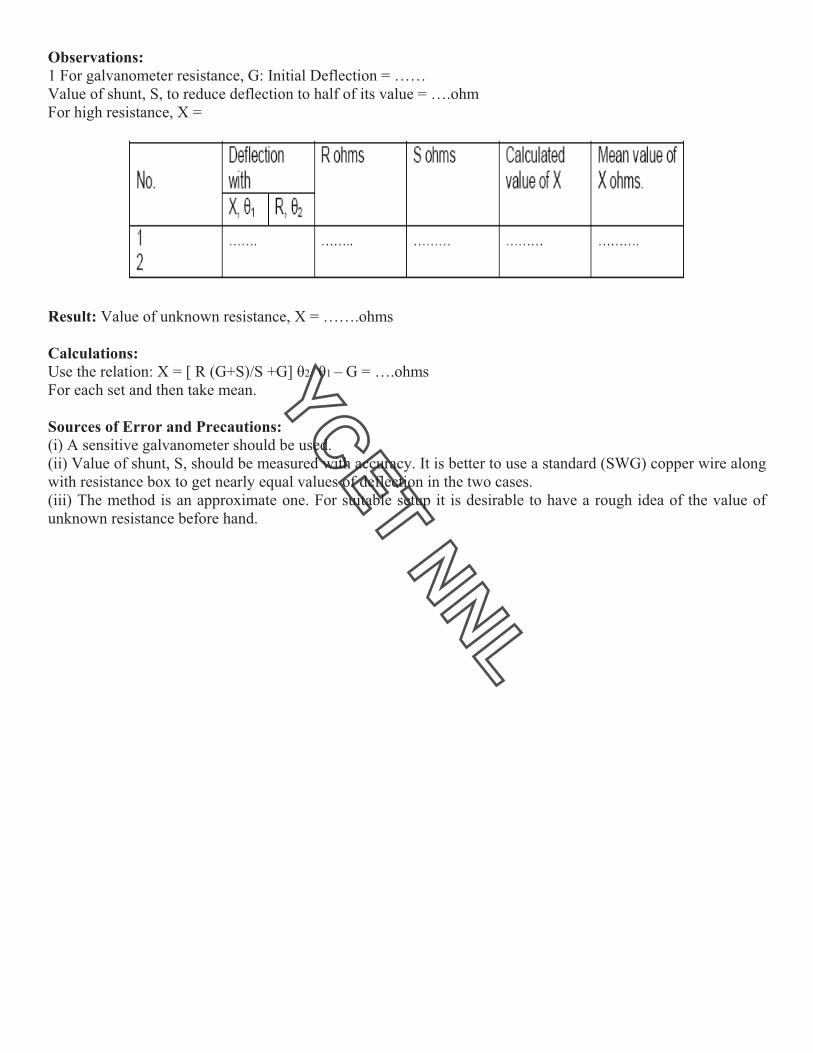
Procedure:
1) To determine the resistance per unit length of the bridge wire:
i) First the circuit is connected as in the fig. for which decimal resistance box X is connected in
the left gap ab and copper strip Y is connected in the right gap of the bridge. Now both the
lower fixed ends of the rheostat are connected to terminals A and C respectively and its variable
end is connected to terminal B.Thereafter the leclanche cell E and the plug key K are joined in
series in between the terminals B, its other end is connected to the jockey D.
ii) The variable end of the rheostat is adjusted in middle such that both the resistances P and Q
are nearly equal.
iii) Now inserting some resistance X through the resistance box, the jockey D is pressed on the
bridge wire and it is slided on it until zero deflection is obtained in the galvanometer. In this
position, the distance l1 of jockey from left end on wire is noted.
iv) Thereafter the positions of resistance box X and copper strip Y are interchanged and then
without changing the resistance box, again the position of jockey is adjusted on the bridge wire
in order to obtain zero deflection in the galvanometer. In this position, the length l2 of the
jockey on the wire from the left end is noted.
v) Now the experiment is repeated three – four times by changing the resistance X from the
resistance box and each time the values of l1 and l2 are noted corresponding to the value of X.
vi) Then using the relationship ! = X/ (l2-l1), the value of ! is calculated for each observation
and its mean value is calculated.
2) To determine the resistance of a given wire:
i) To determine the resistance of a given wire, from the electric circuit as in the fig. The copper
strip connected in the left is withdrawn and in its place the given wire is connected.
ii) The above steps 2, 3, 4 and 5 in part (i) of the experiment are repeated.
iii) Now using the relation Y = X- ! (l2-l1), the value of Y is calculated from each observation
and its mean value is obtained.
Precaution:
(1) For greater sensitivity of the bridge, the resistance connected in the four gaps of the bridge
should be nearly equal.
(2) Clean the ends of connecting wires with sand papers.
(3) Never allow the flow of current in the circuit for long duration otherwise resistance wire will
get heated which in turn increase its resistance. For this, in the circuit insert the plug in key only
while taking observations.
(4) Do not move the jockey on the meter bridge wire by rubbing otherwise thickness of wire
will not remain uniform.
(5) Initially shunt should be used while adjusting galvanometer, but near zero deflection
position, it must be removed.
(6) Only that resistance plug should be removed from the resistance box for which zero
deflection is observed in the middle of the bridge wire. In this state sensitivity of the bridge is
maximum and percentage error is minimum.
(7) Except the resistance removed in the R.B box, all other plugs should be firmly tight.
(8) Before pressing the jockey on the bridge wire, plug should be inserted in the plug key
attached with the cell so that electric circuit gets completed before the galvanometer gets
connected in the circuit.
Result
1. Resistance per unit length of the Carey- Foster’s bridge wire = … ohm/cm
2. Resistance of the given wire = … ohm
Viva – Voce
Q1 What is your experiment?
Q2. Why are you using the Carey Foster’s bridge instead of Meter Bridge?
Q3 Which apparatus are you using to determine the resistance of the wire in your experiment?
Figure:
Observations:
2
Calculations:
(1) For resistance per unit length of bridge wire :
For first observation , != …
For second observation ! = ……….
Mean ! = … ohm/cm
(2). For the resistence of the given wire:
For first observation Y = X- ! (l2-l1) = …….
MeanY= ….. ohm

Exp
Obje
App
of 0
resis
ac)
Form
galv
Then
now
Divi
Note
Proc
1. To
Put i
key,
the g
2. To
(i) C
(ii) N
R ad
(iii)
Figu
periment N
ect: To mea
paratus Used
.1M!, unkn
stance box to
mula Used:
anometer an
n X is discon
used to obta
ding eq. (1)
e if "1= "2, re
cedure:
o find galva
in plug betw
K, and adju
galvanomete
o find unkn
Connect a and
Now open a
djust shunt, S
Increase R i
ure:
No: 2
sure high res
d: A high re
nown high r
o act as shun
: As in the
nd deflection
Ig = E /X+
nnected and
ain deflectio
Ig’ = E/R
by (2) , we g
X=[R(G+
elation reduc
X=R(C+S
anometer re
ween a and b
ust the shunt,
er resistance.
nown high re
d b to bring
and b and c
S in order to
n steps of 0.
sistance by s
esistance sen
resistance (X
nt (S) of gal
fig. this m
n, "1 is obtain
+ G = K"1…
d resistance b
on, "2 in the g
R +SG/S+G
get
+S)/S +G] "2
ces to
S) / S………
esistance:
and note the
, S, such as t
esistance:
unknown re
connect a an
make deflec
1 M! and re
substitution m
nsitive galvan
X) of value
lvanometer,
method, first
ned. Current
………………
box R is con
galvanomete
.S/(S+G) = K
/"1 –G………
………………
e deflection,
to reduce the
sistance into
d b to bring
ction, "2 in th
epeat the ob
method.
nometer (G)
greater than
battery(6-8
t high resist
through gal
………………
nnected. A s
er which is n
K "2 ………
……………
………………
", in the gal
e deflection t
o the circuit.
known resi
he galvanom
servations.
), A high res
n R( may be
volt), one-w
tance, X, is
vanometer i
……… (1)
uitable valu
nearly equal o
……….. (2)
……….. (3)
……… (4)
lvanometer.
to half of its
Note deflec
stance, R int
meter nearly e
istance box
e of the ord
way key (K),
s connected
s
ue of R is int
or equal to "
It should be
previous va
ction "1 in the
to the circui
equal to defl
of about 0.5
der of 1M!)
, two 2-way
to the batt
troduced and
"1.Current no
e fairly large
alue ". Then
e galvanome
it. With suita
lection "1.
5M! in step
), A suitable
y key (ab and
tery through
d shunt, S, i
ow is
e. Then inser
value of S i
eter.
able value o
s
e
d
h
s
rt
s
f
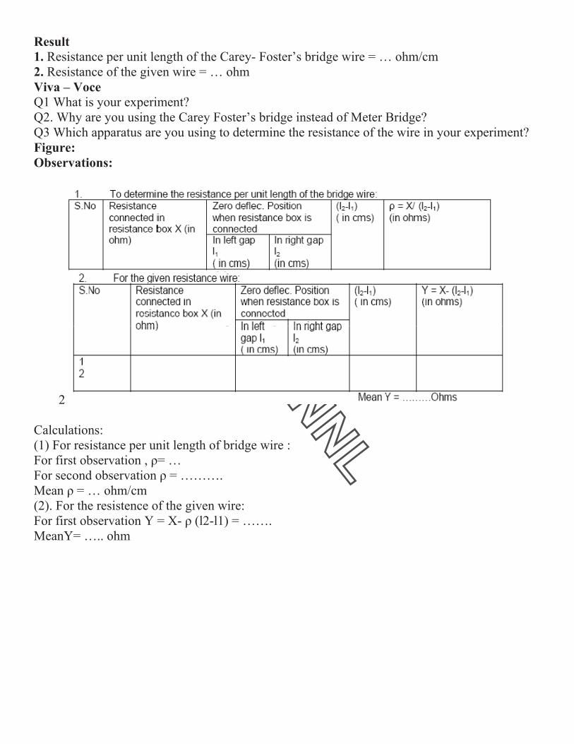
Observations:
1 For galvanometer resistance, G: Initial Deflection = ……
Value of shunt, S, to reduce deflection to half of its value = ….ohm
For high resistance, X =
Result: Value of unknown resistance, X = …….ohms
Calculations:
Use the relation: X = [ R (G+S)/S +G] "2/ "1 – G = ….ohms
For each set and then take mean.
Sources of Error and Precautions:
(i) A sensitive galvanometer should be used.
(ii) Value of shunt, S, should be measured with accuracy. It is better to use a standard (SWG) copper wire along
with resistance box to get nearly equal values of deflection in the two cases.
(iii) The method is an approximate one. For suitable setup it is desirable to have a rough idea of the value of
unknown resistance before hand.
Exp
Obj
App
Con
wire
For
The
R =
Whe
!0 =
ball
!1 =
galv
C =
Pro
(i) M
(ii)
(iii)
Not
(iv)
cond
(v)
Kee
(vi)
first
(vii)
Figu
periment n
ject: To de
paratus Us
ndenser (ca
es.
rmula Used
e high resis
t / 2.3026
ere t = tim
= first throw
istic galvan
= first throw
vanometer
capacity o
ocedure:
Make the e
Close K1(i
Release th
e down the
Repeat th
denser and
Closing K
eping Mors
After a m
t throw !t i
) Repeat pr
ure:
no. - 3
etermine hi
sed: Ballis
apacity of t
d:
stance R is
C log10 !
e period of
w of spot o
nometer.
w of spot o
after a leak
of the stand
electrical co
ii) and pre
he Morse k
e first throw
he procedu
d then disch
K1 (ii) and
se key pres
measured ti
in the galv
rocedure (v
igh resistan
stic Galvan
the order o
given by
0 / !1
f the leaka
of light wh
of light wh
kage of ch
dard conde
onnections
ss the Mor
key K2 so t
w !0.
ure of the
harge throu
d pressing
ssed, open
ime t secon
anometer.
v) and (vi)
nce by the
nometer, ac
of 1.0 or 0.5
ge of cond
hen initially
hen the con
harge for tim
enser.
s as in the f
rse key, i.e
that the co
e points (i
ugh B.G. O
g Morse k
K1 (ii) and
nds, (say 5
for differe
method of
ccumulator
5 ".F), giv
denser thro
y the conde
ndenser is d
me t throug
fig.
. charge th
ndenser is
ii) and (iii
Obtain mea
key K2, ch
d close K1
5 or 10 sec
ent values
:
f leakage o
r, Morse k
ven resistor
ugh the res
enser is dis
discharged
gh R.
he condens
discharged
i) several
an value of
harge the
(i). Start th
c.) release
of t.
of a conden
ey, two wa
r, stop watc
sistance.
scharged th
d through th
er for 40 s
d through t
times, i.e
f !0
condenser
he stop wa
Morse ke
nser.
ay key, stan
ch and con
hrough
he ballistic
econds.
the galvan
e. every ti
r for the s
atch.
y and note
ndard
nnection
c
nometer.
me charge
same time
e down the
e
e.
e

Observation:
Calculations:
Plot a graph with t on X-axis and log10 !0 / !1 on Y-axis. From this graph obtain the slope as
shown in figure.
The slope of the curve = log10 !0 / !t / t
Value of C (given) = ….. "F = …x.10-6 Farad
Therefore * R = t / 2.3026 C x log10 !0 / !t / t = …ohms.
To calculate Rleak:
The procedure is same as adopted in the measurement of R except that the high resistance is
never put in the circuit.
(i) First charge the condenser for same time and then open key K1.
(ii) Allow the condenser to stand for specific time (say t seconds) which should be measured by
a stop watch.
(iii) After this specific time, release the Morse key and note down the deflection !t’ of light spot
on the scale due to passage of remaining charge of the condenser through the ballistic
galvanometer. Thus t’ is the time for which the condenser is allowed to leak through itself and
!t’ is the first throw of the galvanometer corresponding to the charge left on condenser after
leakage for time t’.
(iv) Repeat this process for different intervals of time for the condenser to leak through itself
and note corresponding throws of the galvanometer.
(v) Since each time condenser in charge for the same time !o will remain the same as taken in
the experiment of determining R.
Result: Resistance of the given resistor is ….ohms.
Sources of Error and Precautions:
(i) The galvanometer coil should be made properly free.
(ii) Tapping key should be used across the galvanometer.
(iii) Condenser should be free from dielectric loss.
(iv) After observing !0, the galvanometer coil should be at rest for observing the value of !t.
(v) Thus true value of high resistance can be calculated by above formula. R has been calculated
previously.
VIVA VOCE
1. What do you leak in order to determine high resistance?
2. What is the time constant of R-C circuit?
3. Why do you say that it is method of determining high resistance?
4. What is the order of resistance you determine?

Exp
Obj
App
cath
oper
Plat
com
Figu
Pro
(i) R
(ii) P
ray
as p
(iii)
Vol
periment N
ject: Meas
paratus Us
hode ray ca
rate the tub
tes; An am
mmutator.
ure:
ocedure:
Record the
Place the s
tube inside
possible to
Switch on
tage” and a
No 4:
surement o
sed: A cath
an be place
be (b) to op
mmeter rang
constants
solenoid su
e the solen
avoid the s
n the power
adjust the v
f e/m by h
hode ray tu
ed; A cont
perate the
ge (range d
of the sole
uch that its
noid at the c
stray magn
r supply un
voltage, V
elical meth
ube, a sole
trol which
solenoid (c
d.c. one am
enoid and t
axis lies in
centre. The
netic field.
nit. Turn th
V, to any de
hod.
enoid of pro
contains un
c) to provid
mpere); Vol
tube.
n the east w
e power un
he potentio
esired valu
oper dimen
nder it a po
de variable
ltmeter (ra
west direct
nit should b
ometer mar
e.
nsion, in th
ower supp
e a.c.voltag
nge 1.5 k-v
tion. Moun
be kept as
rked “Acce
he interior
ly and con
ge for defle
volts); One
nt the catho
far away
elerating
of which a
ntrols (a) to
ection
e
ode
a
o

With the help of F and I make a fine and clear spot on the cathode ray tube.
(iv) Apply a.c deflecting potential to one set of plates, say X-plates. A deflection of 2 cm.
is adequate for the experiment.
Now turn on the solenoid current and increase the current till the line is
reduced to a small point. Reverse the solenoid current and readjust the control to a
fine point. The average of these two currents in amperes is I.
(v) Repeat procedures of point (iv) above with Y-plates. Keep deflection 2cm.
Find I.
(vi) Now repeat the whole procedure from point (iii) to (iv) with three other values of
accelerating voltages. It will be necessary to refocus the spot in the tube at
each voltage.
Result: e/m = ….emu/gm. = ….coul/kg.
Observations:
(A) 1. Distance between the edge of X-plate and the screen lx, = …cm.
2. Distance between the edge of Y-plate and the screen ly, = …cm.
3. Diameter of the solenoid D, = …..cm.
4. Length of the winding L, = …cm.
5. Number of turns, N = ….cm.
6. Cos ! = L / " (L2 + D2) = ….
Calculations:
(A) Using X-plates: (e/m)x = [5 x 10⁹( L /Nlx cos!)2] V/I2 e.m.u./gm.
(B) Using Y-plates: (e/m) = [5 x 10⁹(L/Nly cos!)2] V/I2 e.m.u./gm.
The mean of these two values gives the value of e/m.
Sources of Error and Precautions:
(i) Accelerating voltage should be applied carefully.
(ii) Obtain a clear, well focused, sharp line on screen of cathode ray tube. It should
be of moderate size.

Experiment No 5:
Object: To determine the ionization potential of the gas filled thyratron.
Apparatus: A thyratron tube 884, two grid bias supplies (0-30 V), two voltmeters (0- 30 V), a
micro ammeter (or a sensitive galvanometer), two rheostats.
Procedure:
(i) Make the electrical connections as in the fig.
(ii) Keep both the grid and the plate at zero potential. There will be some deflection in
the !A on heating the filament. To reduce it to zero, apply just necessary negative
potential to the plate (keeping grid at zero potential).Keep this plate voltage constant
throughout the experiment.
(iii) Now apply positive potential to the grid. Increase it gradually in small steps and
corresponding deflections in the micro ammeter (or galvanometer). It will be
observed that for particular value of grid, deflection increases very much.
(iv) Draw a graph between deflection (on Y-axis) and grid potential (on X-axis) as in fig.
(v) From the curve, the value of grid voltage corresponding to steep rise of micro
ammeter deflection (showing plate current) is calculated. This gives the ionization
potential; of the gas filled in thyratron.
Figure :

(vi) Remove the micro ammeter from the plate circuit and connect it in the grid circuit as in
the fig.
(vii) Keeping the same plate potential (fixed in the point (ii)), give negative potential to the
grid just to reduce any deflection in !A to zero. Note down this value which will be
subtracted from the calculated value of ionization potential to find the correct value of the
latter.
Result:
Ionization potential of the gas filled in thyratron valve = value from graph-velocity correction =
volts.
Standard Value = ….volts
Percentage Error = ….
Sources of Error and Precautions:
(i) Micro ammeter or galvanometer used in the experiment should be very much
sensitive.
(ii) Velocity correction should be determined carefully.
Observations:
(A) Readings for ionization Potential:
Plate Potential = ….volts.
(B) Velocity Correction:
Grid voltage = ….volts
Calculations:
Plot the graph in grid voltage and corresponding deflection in micro ammeter. Find the value of
ionization potential.
VIVA VOCE
1. What do you mean by ionization potential?
2. Of what substance are you finding the ionization potential?
3. What is gas in the thyratron valve?
4. What is a thyratron valve?
5. What is their construction?

Exp
Objcarry
estim
.
Appcomm
conn
ForThe
F = 2
Whe
r = r
i = c
x = d
If F i
F = H
Thus
F = 2
Proc(i) P
coil.
whol
need
in th
(ii) T
curre
with
curre
the d
little
to re
periment N
ject: To plo
ying current
mate from it
paratus Remutator, plu
nective wires
rmula Usedfield F along
2 ! n r2 i / 1
ere n = numb
adius of the
urrent in am
distance of th
is made perp
H tan " s
2! n r2 i /10
cedure:lace the mag
By rotating
le apparatus
dle and its im
he same verti
To set the co
ent in one di
h the help of
ent and again
deflection. If
e, adjust poin
ead 0-0 till th
No 6:
ot graph show
and to
the radius of
equired: ta
ug key and
s.
d:g the axis of
0 (x2 + r2) 3/2
ber of turns i
coils
mpere flowing
he point from
pendicular to
0(x2 + r2) 3/2 =
gnetometer c
the
in the horiz
mage all lies
ical plane. R
oil exactly in
irection
commutator
n note down
f the deflecti
nter ends
hese deflectio
wing the var
f the coil
angent galva
f a coil is giv
2
in the coil
g in the coil
m the centre
o H earth’s
=H tan "
compass box
zontal plane,
Rotate the com
n the magneti
r and note do
n
ions are equa
ons become
riation of ma
anometer of
ven by
of the coil.
horizontal f
x on the slidi
set the coil
mpass box ti
ic meridian s
own the defl
al then the co
equal.
agnetic field
the Stewart
field, the de
ing bench so
in the magne
ill the pointe
set up the el
ection of the
oil is in mag
with distanc
and Gee typ
eflection " o
o that its mag
etic meridian
er ends read
ectrical conn
e needle. No
gnetic meridi
ce along the
pe, a strong b
of the needle
gnetic needle
n roughly. In
0-0 on the c
nections as i
w reverse th
ian otherwis
axis of a cir
battery, a rhe
e is given by
e is at the ce
n this case th
circular scale
in the fig. Se
he direction o
se turn the ap
rcular coil
eostat, a
y:
entre of the
he coil,
e.
end the
of the
pparatus a

(iii) Using rheostat Rh adjust the current such that the deflections of nearly 70o to 750 is produced in the compass
needle placed at the
centre of the coil. Read both the ends of the pointer. Reverse the direction of the current and again read both the
ends of the pointer.
The mean of four readings will give the mean deflection at x = 0.
(iv) Now shift the compass needle through 2cm. each time along the axis of the coil and for each position note
down the mean
deflection. Continue this process till the compass box reaches the end of the bench.
(v) Repeat the measurements exactly in the same manner on the either side of the coil.
(vi) Plot a graph taking x along the axis and tan " along the y-axis.
(vii) Mark the points of inflexion on the curve. The distance between the two points will be the radius of the
coil.
Observation:
Result: The graph shows the variation of the magnetic field along the axis of a circular coil carrying current.
The distance between the
points of inflexion P, Q and hence the radius of the coil = …cms.
Precautions and Sources of Error: (i) The coil should be carefully adjusted in the magnetic meridian.
(ii) All the magnetic materials and current carrying conductors should be at a considerable distances from the
apparatus.
(iii) The current passed in the coil should be of such a value as to produce a deflection of nearly 750.
(iv) Current should be checked from time to time and for this purpose am ammeter should be connected in
series with the battery.
(v) Parallax should be removed while reading the position of the pointer. Both ends of the pointer should be
read.
(vi) The curve should be drawn smoothly.
VIVA VOCE 1. What is the direction of the field?
2. Is the field uniform at the centre?
3 Hoe can you get wider region of uniform field?
4 Is it true for any direction of current in the two coils?
5 If any current carrying conductor is placed close to the coil ten will it effect your measurement?
!

EXP
Obje
by m
App
coup
Form
The
Whe
E = r
L = l
Proc
(i) T
resis
(ii) N
so ad
the p
(iii)
junct
that
(iv)
decr
(v) C
(vi)
therm
(vii)
place
third
Now
temp
Figu
PERIMEN
ect: To stud
means of a po
paratus Used
ple, high resi
mula Used:
thermo elect
ere ! = resist
resistance ta
length of the
cedure:
The electric
stance of 1,0
Now jockey
djusted that
potential diff
Open K2 (i
tion has bec
again a bala
Repeat the
easing temp
Calculate the
Plot the gra
mo e.m.f.’s,
In order to
ed in a wate
d of naphthal
w calculate th
perature. Thi
ure:
NT NO. 7:
dy the variat
otentiometer
d: Potentiom
istance box,
tric e.m.f. (e
tance per uni
aken out from
e potentiome
connections
18 ohms is t
is placed at
there is no d
ference acro
i) and conne
come steady
ance point is
above proc
eratures of t
e value of e.m
aph between
as ordinates
determine
er bath for h
lene melts, t
he e.m.f. cor
is temperatu
:
ion of the th
r and to deter
meter( coil ty
high resistan
e) developed
it length of t
m the resistan
eter wire wh
s are made
taken out fro
t the point A
deflection in
ss the R.B. T
ect K2 (ii) s
, press the j
observed. N
cedure and d
the hot juncti
m.f generate
n the temper
s. The curve
the melting
heating. The
the balance p
rresponding
ure will be th
hermo electr
rmine (i) the
ype or 10 w
nce rheostat
d in a thermo
e
the potentiom
nce box (res
en thermo e
as shown i
om the resist
A and the key
n the galvano
This is know
o that the th
ockey on th
Note the leng
determine th
ion.
ed using the f
rature differe
is of the sha
point of na
hot junction
point is obta
to this leng
he melting po
ric e.m.f. wit
e neutral tem
wire), standar
, one way ke
ocouple is ob
= ! El / R
meter wire,
sistance acro
.m.f. is balan
in fig. 2 Th
tance box.
y K1 and K2
ometer. In th
wn as standar
hermocouple
he wire by ad
gth (l) of the
he balancing
formula used
ences of tw
ape as shown
aphthalene, w
n of the ther
ained on the
gth. With the
oint of napht
th temperatu
mperature, (ii
rd cadmium
ey, two way
btained with
oss which the
nced.
he rheostat
2 (i) are clos
his way the e
rdization of t
e is in circu
djusting the
potentiomet
g lengths of
d.
o junctions
n in figure.
we take the
rmocouple is
potentiomet
e help of the
thalene.
ure, for a co
i) melting po
m cell, battery
and connect
the help of t
e standard ce
Rh should b
sed. The val
e.m.f. of stan
the potentiom
it. When the
length of th
ter wire from
f the potent
as abscissae
naphthalene
s placed in n
ter. Note dow
e graph deter
opper-iron th
oint of napht
y, a copper
tion wires.
the following
ell is balance
be of high
lue of the rh
ndard cell is
meter wire.
e temperatur
he potentiom
m A to balanc
tiometer wir
e and the co
e in a tube.
naphthalene
wn the balan
rmine the co
hermocouple
thalene.
iron thermo
g formula:
ed)
value and a
eostats Rh i
balanced by
re of the ho
meter wire so
cing point.
re at variou
orresponding
This tube i
. When two
ncing length
orresponding
e,
-
a
s
y
ot
o
s
g
s
-
h.
g

Observations:
(i) E.M.F. of the standard cadmium cell E = …volts
(ii) Resistance, introduced in the resistance box R.B. = …ohms
(iii) Resistance per unit length of the potentiometer wire (!) = …ohm/cm
(iv) Table for the determination of thermo e.m.f.’s with temperature.
Room Temperature = ….oC
(v) Balancing length when naphthalene melts = …cm
Calculations:
(i) At ….oC, e = E ! l / R = …micro volts
(ii) At ….oC, e = E ! l / R = …micro volts
Similarly calculate for other temperatures.
Result:
(i) The variation of thermo e.m.f. of the copper iron thermocouple with temperature is shown in the graph
Neutral temp. from graph = …oC
(ii) Melting point of naphthalene = …..oC
Standard Result: The neutral temperature for … couple = …oC.
Melting point of naphthalene = …oC
Precautions and Sources of Error:
(i) If the resistance per unit length ! of the potentiometer wire is not known, determine with the help of a post
office box.
(ii) It is essential to check the standardization of the potentiometer after two or three readings.
(iii) The ends of connections wires should be properly cleaned.
(iv) The battery employed in this experiment should be fully charged.
(v) The jockey should be pressed gently and momentarily.
(vi) The galvanometer employed in this experiment should be a sensitive one and it should be shunted in the
initial stages of locating the null point.
(vii) The temperature of the hot junction should be recorded at the time of taking the balance reading of
potentiometer.
VIVA VOCE
1. What is thermocouple?
2. What is thermo-electric effect?
3. On what factors does the direction of thermoelectric current depend?
4. What is neutral temperature?
5. Is it same for every thermocouple?
6. What is temperature of inversion?
7. Is it same for every couple?
8. What is their value for Cu-Fe thermocouple?
9. What are the values of thermo e.m.f. for the following couples? Antimony-bismuth couple, Copper-
constantan couple and Copper-iron.
10. What is Peltier Effect?
11. What is Thomson Effect?

Experiment No 8:
Object: To determine the value of Planck’s constant h by a photo cell.
Apparatus Used: Vacuum type photo-emissive cell mounted in a wooden box provided with a wide slit, optical bench with uprights,
D.C. power supply, resistance box. Rheostat, a set f filters,ballistic galvanometer, taping key, lamp and scale arrangements and
connection wires.
Formula Used: The value of Planck’s constant h is given by: h = e (V2 – V1) !1 !2 / c(!1 - !2)
Where e = electronic charge, V2 = stopping potential, V1 = stopping potential, c = velocity of light.
Procedure:
(i) The electrical connections are made.
(ii) The lamp and scale arrangements are adjusted to get a well focused spot on the zero mark of the scale. The photocell is mounted at
one end of the optical bench. At the same level and nearly 60-80 cm. from the photocell, a light source is arranged. The light is
allowed to fall on the cathode of photocell. Now a suitable filter of known wavelength is placed in the path of ray reaching to
photocell.
(iii) A deflection is observed in ballistic galvanometer.i.e. the spot of light moves on the scale. If the spot moves out of the scale, then
it is adjusted on the scale with the help of rheostat R connected in series of ballistic galvanometer. This deflection corresponds to zero
anode potential as key K1 is open.
(iv) A small negative potential is applied on the anode by closing key k1 and adjusting the rheostat Rh. This voltage is recorded with
the help of voltmeter. The corresponding galvanometer deflection is noted by noting the deflection of spot on the scale.
(v) The negative anode potential is gradually increased in small steps and each time corresponding deflection is noted till the
galvanometer deflection is reduced to zero.
(vi) The experiment is repeated after replacing the green filter in succession by two filters e.g. blue and yellow.
(vii) Taking negative anode potentials on X-axis and corresponding deflections on Y-axis, graphs are plotted for different filters.
Figure :
Observations:
Graph: the graph between anode potentials and galvanometer deflection is shown in the fig.
From graph, the stopping potentials are:
For yellow filter V1 = ….volts
Foe green filter V2 = …..Volts
For blue filter V3 = ….volts.
Calculations:
Electronic charge e = 1.6 x 10⁻¹⁹
coulombs
Speed of light c = 3 x 10⁸
m/sec.
Wavelength of yellow filter !1 = ………A0
= ….m
Wavelength of green filter !2 = ……… A0
= ….m
Wavelength of blue filter !3 = ……… A0
= ….m
1. for yellow and green filters
h = e (V2 – V1) !1 !2 / c (!1 - !2) = ………..joule-sec.
2. for green and blue filters:
h = e (V3 – V2) !2 !3 / c (!2 - !3) = ………..joule-sec.
3. for yellow and blue filters:
h = e (V3 – V1) !1 !3 / c (!1 - !3) = ………..joule-sec.
Mean value of Planck’s constant = ….+….+…./3 = ….joule-sec.
Standard Value: Standard value of Planck’s constant = 6.625 *10 -34joule-sec
Percentage Error:
% error = experimental value ~ standard value / standard value x 100 = …. %
Result: The value of Planck’s constant = …..Joules-sec.
Sources of Error and Precautions:
(i) The experiment should be performed in a dark room to avoid any stray light to photocell.
(ii) The observations should be taken by altering anode potential in small steps of 0.05 volts
(iii) Corresponding to zero anode potential, the deflection of light spot on scale should be adjusted at its maximum value.
(iv) Smooth graphs should be plotted.
(v) Stopping potentials should be read carefully.
(vi) The experiment should be performed at least with three filters.

Experiment no 9:
Object: To determine the self inductance of given coil by Rayleigh’s method.
Apparatus Used: Post office box, ballistic galvanometer, stop watch, decimal ohm box, an
accumulator, given inductance, rheostat ( 4 or 5 ohms.), tapping key, double key, a stretched
resistance wire and connection wires.
Formula Used:
Self inductance (L) of the coil is given by:
L = r/! T/2" .# (1+$/2)
Where r = small resistance (0.1 or 0.01 ohm) introduced in series with the inductance,
! = steady deflection in ballistic galvanometer when r is introduced in the circuit,
T = time period of the coil of galvanometer,
# = first throw of the galvanometer when inductance L is employed in the circuit,
$ = logarithmic decrement = 2.3026 x 1/10 log10 #1/ #11
Where #1 and #11 are first and eleventh observed throw of the galvanometer respectively.
Procedure:
(i) Set the galvanometer and lamp and scale arrangement such that the spot of light moves
freely on both sides of zero of the scale.
(ii) Make the electrical connections as in the fig.
(iii) Fix the ration P: Q at 10:10. Pressing K1 and K2 adjust the resistance in R arm and the
sliding contact on r’ such that there is no deflection in the ballistic galvanometer. Here first of
all the battery arm should be adjusted to have a near balance with the help of R and thenrheotat
r’. In this case the resistance, r in resistance box should be zero.
(iv) Keeping K1 and K2 pressed introduce a small resistance say 0.01ohm in the resistance box
and obtain the steady deflection ! in the galvanometer.
(v) Repeat the above procedure for other small values of r and obtain the steady deflection ! in
each case.
(vi) Keeping r = 0 again obtain the balance point. With K2 keeping pressed, break the cell
circuit by releasing K1. Note down the first throw. Repeat this observation two or three times,
each after checking steady balance.
(vii) Now to note #1 and #11 first break cell circuit by releasing key, K1 and then immediately
after it, release galvanometer key K2. the spot will oscillate on the scale. Measure #1 and #11.
Repeat the process three or four times.
(viii) Now disconnect galvanometer from the bridge and by touching its connecting wires with
mouth, make its coil oscillating. Note the time for different oscillations and then calculate the
time period T of the galvanometer coil.

Figu
Obs
(1):
(2) R
Cal
Res
ure:
servations
Reading f
Reading fo
culations:
sult: The se
s
for the dete
or determin
$ = 2.30
L = r/! T
elf inducta
ermination
nation of th
26 x 1/10
T/2" .# (1+
ance of the
n of # and %
he time per
log10 #1/ #
+$/2) = …
coil L = …
%
riod
#11
….henrys.
….henrys.

Precautions and Sources of Error:
(i) The galvanometer coil should be freely moved in the space between the pole pieces.
(ii) Tapping key should be connected across the galvanometer
(iii) To get a suitable deflection in the galvanometer a high adjustable resistance should be
connected in series with cell.
(iv) All resistances used in the experiment should be non inductive.
(v) To secure maximum sensitiveness of the bridge all the four arms of the bridge should have
nearly equal resistance.
(vi) The connection wires should be uncoiled.
(vii) The resistance introduced in the resistance box should be very small so that it may not
affect the value of the steady current in that branch appreciably.
(viii) While determining the time period of the galvanometer, the galvanometer circuit should
be kept open.
(ix) Keys K1 and K2 may have to be released in quick succession by personal judgment. For
better results a Raleigh key should be used.
VIVA VOCE
1 Define self inductance.
2 What is the unit of self inductance?
3 Define a Henry.
4 Why do you take inductance coil in the form of helix, and not as a straight conductor?
5 Upon what factors does the value of flux depend?
6 Why do you observe steady deflection by introducing a small resistance ® in the circuit? Why
not large resistance?
7 What type of connecting wires should be used and why?
8 Suppose L1 and L2 be the self inductance of the two circuits and k be coupling coefficient
between them, then what is mutual inductance?

Exp
Obje
the n
App
and s
amm
Form
appli
that
cryst
(i) H
(ii) H
Whe
= VH
(iii) N
(iv) H
(v) M
Proc
1 Pla
conn
2 Al
semi
milli
3 Ch
Ix va
4 Me
in th
Figu
periment 1
ect: To study
number of ch
paratus Req
search coil,
meter, keys.
mula Used:
ied along Z-
are normal t
tal is !, then
Hall voltage,
Hall coeffici
ere VH is in
H /Ix . d/BZ m
No. of charg
Hall angle: "
Mobility: m!
cedure:
ace the speci
nections as in
low some cu
iconductor c
ivoltmeter an
hange value o
alues. It will
easure magn
he crystal, Bz
ure:
10:
y hall effect
harge carrier
uired: A rec
calibrated fl
As shown in
-axis. Curren
to Y-axis. Lx
n actual magn
VH, is measu
ent: RH = VH
volts, Ix is in
met3/coulom
ge carriers pe
" = VH /Vx .
W
! = " / BZ ra
imen in the m
n fig.
urrent, Ix, wi
crystal along
nd Vx by vo
of Ix in step
l be a straigh
netic field, B
z = !B.
in an N-typ
rs per unit vo
ctangular sla
ux meter to
n the fig. d i
nt, Ix, is mad
x is the lengt
netic field w
ured with th
H /Ix . d/BZ .
n amperes, d
mb.
er unit volum
n = -1/R
Where e = 1
. lx /b rad.
Where lx an
d.met2 / We
magnetic fie
ith the help o
X-axis. Me
oltmeter.
s by rheosta
ht line whose
B, with a gau
e semicondu
olume, (iii) H
ab of semico
measure ma
s the thickne
de to flow alo
th of the cry
within the cry
he help of mi
104 met.3/c
d is in meter
me in the sem
RH .e met.3
1.6 x 10⁻¹⁹
co
nd b both are
eber.
eld of the stro
of rheostat, R
asure Hall v
t, Rh, and no
e slope will b
ss meter or f
uctor. To det
Hall angle an
onductor crys
agnet field or
ess along Z-a
ong X-axis.
stal along X
ystal is Bz =
illivoltmeter
coulomb
rs and BZ in g
miconductor
oul.
e in meter.
ong magnet
Rh, to flow t
voltage, VH, w
ote correspo
be given by V
flux meter an
termine (i) H
nd mobility.
stal of thickn
r ballistic ga
axis of the c
Hall voltage
X-axis. If perm
!B.
r.
gauss. If BZ
r crystal, n, i
and make ot
through the
with the help
nding values
VH / Ix.
nd find the a
Hall voltage
ness about 0
alvanometer,
crystal. Magn
e VH, is deve
meability of
is measured
is given by:
ther
p of
s of VH and
actual field
and Hall coe
.3 mm, elect
millivoltme
netic field, B
eloped acros
f the medium
d in weber/m
efficient, (ii)
tromagnet,
eter, battery
B, is also
ss the faces
m of the
met2 then RH
)

Observations:
1 Permeability of the specimen, ! = ……..
Magnetic field B = …….. gauss or weber/met2.
Actual field in the crystal BZ = !B = ….. gauss or weber/met2.
2 Width of the crystal along Z-axis, d = ……. met
Width of the crystal along Y-axis, b = ……. met
Length of the crystal along X-axis, lx = …… met
3 Measurement of Hall voltage:
Calculations:
1 A graph is plotted in VH and Ix. From its slope tan # = VH / Ix = BC/AB is found.
Then Hall coefficient is RH = tan #. d/BZ . 104 met3/coul. = ….met3/coul.
2 The number of charge carriers per unit volume n = - 1 / RH.e = ……
3 Hall angle, " = VH /Vx . lx/b = …..rad.
4 Mobility, m! = "/BZ= …….rad.met2/weber.
Result:
Hall coefficient, RH = ………………met3/coul
No. of charge carriers, n = ……………..
Hall angle " = ……………….rad.
Mobility m! = rad.met2/weber.
Sources of Error and Precautions:
1 Hall voltage developed is very small and should be measured accurately with the help of a millivoltmeter of
potentiometer.
2 Current through the crystal should be strictly within the permissible limits.
VIVA VOCE
1 What is Hall Effect?
2 On what factors the sign of Hall potential depends?
3 Illustrate the above questions 1and 2.
4 How do you define Hall coefficient?
5 What is mobility?
Figure 1:
Graph:

Exp
Obje
Appconn
Proc
(A) F(i) C(ii) Wread(iii) P
(B) R(i) Mbias
Figu
Obs
periment
ect: To dra
paratus Renection wire
cedure:
Forward BConnectionsWith the helding of currePlot a graph
Reverse BMake the cosing.
ure:!
servations:
no 11:
aw the chara
quired: traes.
Biasing:s are made lp of rheostent in millimh in applied
iasing:onnections a
:
acteristics o
ansistor, mil
as in the fitat, apply dmeters.d voltages a
as in the fig
of PN junct
limeter and
g.ifferent volt
and corresp
g. and proce
tion diode.
d micro amm
tages to the
ponding cur
eed exactly
meter, batte
e PN junctio
rrents.
y in the sam
ery, rheosta
on and note
me way as o
at, voltmete
e the corres
opted for fo
er and
sponding
orward
!
Calculations: (Graph plotting): Plot two graphs- one for forward and other for reverse biasing between voltages applied and the corresponding currents
!
Result: The characteristic of junction diode ( ) are shown in the graphs.
Sources of Error and Precautions:
(i) To avoid over heating of the transistor, current should not be passed for long durations. (ii) Voltages applied should be well below the safety limit of the transistor. (iii) Connections should be made carefully.
VIVA-VOCE:1. What is a PN junction diode? 2. What do you mean by P-type germanium and N-type germanium? 3. What property PN junction exhibits? 4. What is the order of currents in the above two cases? 5. Mention the order of voltages with it. 6. What if high voltage is applied in forward bias? 7. Have you heard of turn over voltage?
!
!
!
!
Experiment No. 12:
Object: To determine the energy band gap of a semiconductor (germanium) using four probe method.
Apparatus Required: Probes arrangement (it should have four probes, coated with zinc at the tips. The probes
should be equally spaced and must be in good electrical contact with the sample), Sample (germanium or silicon
crystal chip with non-conducting base), Oven (for the variation of temperature of the crystal from room
temperature to about 2000C), A constant current generator (open circuit voltage about 20 V, current range 0 to
10 mA), Millivoltmeter (range from 100mV to 3V, electronic is better.), power supply for oven, thermometer
Formula Used: The energy band gap, Eg, of semiconductor is given by Eg = 2k. 2.3026 x log10 ! / 1/T(in K) in
eV. Where K is Boltzmann constant equal to 8.6 x 10⁻⁵ ev/deg., and ‘!’is the resistivity of the semiconductor
crystal, given by ! = !o / f (W/s) Where !o = V/I x 2"s. For function f (W/s) refer to the data table given in the
calculations. S is the distance between the probes and W is the thickness of semi conducting crystal. V and I are
the voltages and current across and through the crystal chip.
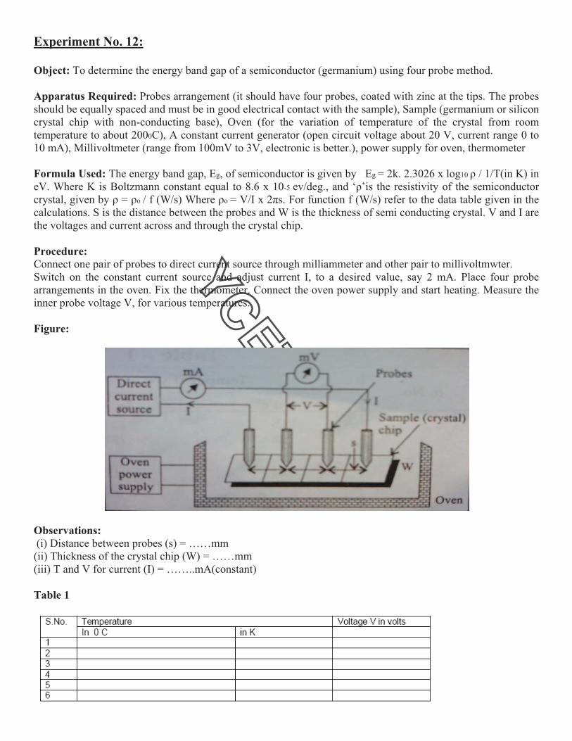
Procedure:
Connect one pair of probes to direct current source through milliammeter and other pair to millivoltmwter.
Switch on the constant current source and adjust current I, to a desired value, say 2 mA. Place four probe
arrangements in the oven. Fix the thermometer. Connect the oven power supply and start heating. Measure the
inner probe voltage V, for various temperatures.
Figure:
Observations:
(i) Distance between probes (s) = ……mm
(ii) Thickness of the crystal chip (W) = ……mm
(iii) T and V for current (I) = ……..mA(constant)
Table 1
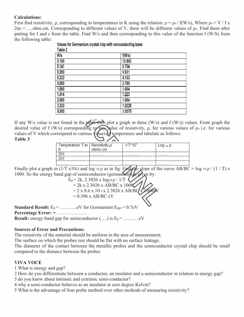
Calculations:
First find resistivity, !, corresponding to temperatures in K using the relation: ! = !o / f(W/s), Where !o = V / I x
2"s = ….ohm.cm. Corresponding to different values of V, there will be different values of !o. Find them after
putting for I and s from the table. Find W/s and then corresponding to this value of the function f (W/S) from
the following table:
If any W/s value is not found in the table then plot a graph in these (W/s) and f (W/s) values. From graph the
desired value of f (W/s) corresponding to any value of resistivity, !, for various values of !o i.e. for various
values of V which correspond to various values of temperature and tabulate as follows:
Table 3
Finally plot a graph in (1/T x103) and log 10 ! as in fig. Find the slope of the curve AB/BC = log 10 ! / (1 / T) x
1000. So the energy band gap of semiconductor (germanium) is given by:
Eg = 2k. 2.3026 x log10 ! / 1/T
= 2k x 2.3026 x AB/BC x 1000
= 2 x 8.6 x 10-5 x 2.3026 x AB/BC x 1000eV
= 0.396 x AB/BC eV
Standard Result: Eg = ………..eV for Germanium Eggs = 0.7eV
Percentage Error: = ……………….
Result: energy band gap for semiconductor (….) is Eg = ……….eV
Sources of Error and Precautions:
The resistivity of the material should be uniform in the area of measurement.
The surface on which the probes rest should be flat with no surface leakage.
The diameter of the contact between the metallic probes and the semiconductor crystal chip should be small
compared to the distance between the probes
VIVA VOCE
1 What is energy and gap?
2 How do you differentiate between a conductor, an insulator and a semiconductor in relation to energy gap?
3 do you know about intrinsic and extrinsic semi-conductor?
4 why a semi-conductor behaves as an insulator at zero degree Kelvin?
5 What is the advantage of four probe method over other methods of measuring resistivity?

Exp
Obje
App
calcu
mA)
Form
Hyst
cycle
F = 5
squa
Proc
(i) A
frequ
obtai
B te
horiz
expe
(ii) V
write
(iii)
form
Figu
periment N
ect: To deter
paratus Req
ulated, capac
), rheostat (1
mula Used:
teresis loss p
e. Where i =
50c/s, Area c
ares of mm.
cedure:
Apply some
uency select
in a suitable
rminals to Y
zontal gain
eriment.
Vary rheosta
e on it V and
Re-sketch a
mula.
ure :
No 13:
rmine the hy
quired: A s
citor (8!F). R
0 ohm).
per unit volu
= current in p
can be count
voltage, V,
tor of CRO
e B-H curve
Y-plates. No
and vertica
at, Rh, to som
d i values.
all B-H curve
ysteresis loss
step down t
Resistor (50
ume per cyc
primary wind
ted in millim
with the he
to external.
on the scree
ote voltage,
al gain of a
me other val
es with V an
s by C.R.O.
ransformer,
0 K" potenti
le is given b
ding in ampe
meter2 from t
elp of rheos
. Now adjus
en. To obtain
V, and curr
amplifiers is
lue. i.e. selec
nd I values o
specimen t
iometer), A.C
by: W = i.V.
ere,V = volta
the centimete
stst, Rh. Con
st gain of th
n a correct c
rent, i. Trac
s selected, t
ct new value
on a centime
transformer
C Voltmeter
.area of B-H
age across p
er graph of B
nnect XX p
he horizontal
curve adjust
ce the curve
they are to
es of V and
eter graph. F
hysteresuis
r (0-10 V), A
H loop / f.# a
rimary wind
B-H loop. Co
plates and Y
l and vertica
value of R,
on the trac
be kept co
i. Trace the
Find the are
loss of wh
A.C milliamm
area of recta
ding correspo
ount the sma
YY plates of
al amplifiers
also may int
ce paper. No
onstant thro
B-H curve o
a in mm2 req
hich is to be
meter (0-500
angle joules
onding to i.
all
f C.R.O.keep
s of CRO to
terchange B
ote that once
ough out the
on paper and
quired in the
e
0
/
p
o
-
e
e
d
e

Observations:
Hysteresis loss per unit volume per cycle is given by
W = i.V Area of B-H loop / f.#.Area of rectangle = ……..joules/cycle
Result: The hysteresis loss of the specimen transformer per unit volume per cycle is ………….joules/cycle.
Precautions:
(i) Attenuator of C.R.O should be kept at a suitable position. The positions of X and Y amplifiers should not be
disturbed after adjusting it once in the whole experiment.
(ii) Variations in the supply voltage will affect the tracing of the curve on the paper.
(iii) Handle C.R.O carefully.