Embed Size (px)
Citation preview

1
EPSONEPSONTraining
Dot Matrix Printer Dot Matrix PrinterTraining GuideTraining Guide
DFX-8500 Training ModuleDFX-8500 Training Module
Class Handouts:Class Handouts:⇒⇒ Troubleshooting AidTroubleshooting Aid
/Observation Sequence/Observation Sequence
⇒⇒ Control Panel ReferenceControl Panel Reference⇒⇒ Functional DiagramFunctional Diagram⇒⇒ Motor Phase ChartsMotor Phase Charts⇒⇒ Junction Board LayoutJunction Board Layout⇒⇒ Print Head Cable LayoutPrint Head Cable Layout⇒⇒ Adjustment SupplementsAdjustment Supplements⇒⇒ Test PointsTest Points⇒⇒ Error Codes / Flow ChartError Codes / Flow Chart⇒⇒ Labs : Operational : MechanicalLabs : Operational : Mechanical

2
EPSONEPSONTraining
DFX - 8500 Training Module DFX - 8500 Training ModuleGeneral SectionGeneral Section
The General Section The General Section contains general information thatcontains general information that
can be applied to all of can be applied to all of EPSON’sEPSON’s DOT MATRIX PRINTERS DOT MATRIX PRINTERS

3
EPSONEPSONTraining
DFX - 8500 Training Module DFX - 8500 Training ModuleGeneral SectionGeneral Section
TRAINING CONCEPTSTRAINING CONCEPTS
!!Screw Types: Machine VS Self-TapScrew Types: Machine VS Self-Tap!!DO NOT.. Over-Tighten screws!DO NOT.. Over-Tighten screws!!!DO NOT.. Pull P-ROMS unless instructedDO NOT.. Pull P-ROMS unless instructed
""DO.. Report broken equipmentDO.. Report broken equipment""DO.. Keep area cleanDO.. Keep area clean""DO.. Be on timeDO.. Be on time
Remember: Epson has a “No-solder” rule for Remember: Epson has a “No-solder” rule for any repairs. Go to the next higher assembly ifany repairs. Go to the next higher assembly if
soldering is required.soldering is required.

4
EPSONEPSONTraining
DFX - 8500 Training Module DFX - 8500 Training ModuleGeneral SectionGeneral Section
PARALLEL INTERFACE TEST CONNECTORPARALLEL INTERFACE TEST CONNECTORThis test plug works with the printer ON-LINE(ready to print data. It confirms operation of the input data latches in the printer I/O.
Install jumpers asindicated on a standardconnector.Pins 2 through 9 areparallel DATA Lines.As jumpered: Prints“H” (HEX 48)
192021222324252627282930313233343536
123456789101112131415161718

5
EPSONEPSONTraining
DFX - 8500 Training Module DFX - 8500 Training ModuleGeneral SectionGeneral Section
Meter Setup: For probing Test PointsMeter Setup: For probing Test PointsSet up your meter with test leads and pins as shown:
STRAIGHT PINS
CONNECTOR
ALLIGATOR LEADSFROM TOOL KIT

6
EPSONEPSONTraining
DFX - 8500 Training Module DFX - 8500 Training ModuleGeneral SectionGeneral Section
LUBRICATION LISTLUBRICATION LIST
LUBE CODELUBE CODE DESCRIPTIONDESCRIPTION PART #PART #---------------------------------- ------------------------------------------ ------------------------------G-2G-2 GREASEGREASE B700200011B700200011G-20G-20 CLEAR GREASECLEAR GREASE B702000001B702000001G-26G-26 WHITE GREASEWHITE GREASE B702600001B702600001G-27G-27 GREASEGREASE B702700001B702700001G-37G-37 GREASEGREASE B703700001B703700001O-2O-2 LIGHT OILLIGHT OIL B710200001B7102000010-80-8 OIL(plastics)OIL(plastics) 10197531019753O-12O-12 OIL(combination gears)OIL(combination gears) 10389911038991
The following list of lubricants specified in the Maintenance Section of our various printer manuals. When performing PM routines, match the lubricant number to thislist so you can order the correct product.

7
EPSONEPSONTraining
DFX - 8500 Training Module DFX - 8500 Training ModuleGeneral SectionGeneral Section
MOTOR PHASE CHARTSMOTOR PHASE CHARTSThe following three pages identifies some minorThe following three pages identifies some minordifference between stepper motors used withindifference between stepper motors used withinEpson Printer Products that use a 4 wire, 5 wire, Epson Printer Products that use a 4 wire, 5 wire, or a 6 wire configuration.or a 6 wire configuration.

8
EPSONEPSONTraining
DFX - 8500 Training Module DFX - 8500 Training ModuleGeneral SectionGeneral Section
MOTOR PHASE 4 wireMOTOR PHASE 4 wireA
B
C
D
MOTOR
52 OHM
52 OHM
A
B
C
D
DRIVER CHECK MOTORCHECK
DIODE
CHECKVO
LTAGE
RESISTA
NCE
0.58
DIODE
CHECK
VOLTAGE
RESISTA
NCE
52.4PCB
4-WIRE STEPPER MOTOR CHECKS
The motor has only 4 leads connected. Each pair is two phases, depending on which way polarity is applied. There is no seperate ground lead. Just check resistance across each of the two pair. They should be within 10% of each other.

9
EPSONEPSONTraining
DFX - 8500 Training Module DFX - 8500 Training ModuleGeneral SectionGeneral Section
MOTOR PHASE 5 wireMOTOR PHASE 5 wire
GND
A
B
C
D
MOTOR
52 OHM
52 OHM
A
GND
B
C
D
DRIVER CHECK MOTORCHECK
DIODE
CHECK
VOLT
AGE
RESIS
TANCE
0.58RED TOGND
DIODE
CHECK
VOLT
AGE
RESIS
TANCE
52.4PCB
5-WIRE STEPPER MOTOR CHECKS
Five wires are connected to the motor. The GROUND line is common to bothcoils in the motor, so you can check any of the 4 phases by referencing the single ground connection. The phases should all measure within 10% of each other.
10
EPSONEPSONTraining
DFX - 8500 Training Module DFX - 8500 Training ModuleGeneral SectionGeneral Section
MOTOR PHASE 6 wireMOTOR PHASE 6 wire
GND
GND
A
B
C
D
MOTOR
52 OHM
52 OHM
A
GND
GND
B
C
D
DRIVER CHECK MOTORCHECK
DIODE
CHECK
VOLTAGE
RESIS
TANCE
0.58RED TOGND
DIODE
CHECK
VOLTAGE
RESIS
TANCE
52.4PCB
6-WIRE STEPPER MOTOR CHECKS
The motor has 6 leads connected. Each coil in the motor has a seperate ground. Check each phase by referencing its associated ground. Each goround refernces 2 pahases. The 4 phases shouldbe within 10% of each other.

11
EPSONEPSONTraining
Communication Errors:1) - Always check all cable connections (power cord, communications cable,etc.).2) - Try another cable.If available, try another computer.3) - Start at the Default Settings and work your way up to the settings the customer wants.4) - Always disconnect cable from Computer and Perform a Self- test ( feature/demo print) then work up .5) - Always try to print from DOS( I.E. - DIR > LPT1 (ENTER))6) - Once the above has been done, then go into Customer's Application. (if everything else is O.K.)7) - Have them check their printer settings (I.E. - port , port settings if serial-baud,parity, etc.).8) - Ensure the proper port is in use. If they have multiple try another other port.9) - Try reloading printer Driver (remove the old driver).
Print Quality Errors:1) - Try a new consumable (if ink jet, attempt cleaning cycles)2) - Ensure that the consumable is Genuine (not 3rd party or refilled).3) - Ensure the proper Preventative Maintenance has been performed (located in the User's Manual).4) - If Dot Matrix or Ink Jet, ensure the proper Paper thickness is selected ( refer to the User's Manual).5) - Paper Specifications (Quality, thickness, printable side, etc.)( located in the User’s Manual ).6) - Alignment concerns, set to Unidirectional for best possible quality.7) - Set printer and Application Program to their defaults .8) - Perform a self-test (feature/demo print).9) - Try a different Application Program.
DFX - 8500 Training Module DFX - 8500 Training ModuleGeneral SectionGeneral Section
General Trouble Shooting TipsGeneral Trouble Shooting Tips

12
EPSONEPSONTraining
Jamming or Critical Errors:1) - Check paper path and print head path for obstructions.2) - Check for broken/blocked sensors/gears3) - Ask how often it happens.4) - Explain paper specifications (located the User's Guide).5) - If labels are used with Dot Matrix - Never back labels out. Check for jammed labels.6) - If using labels with Ink Jet / Laser, ensure that the labels are within specifications for the aprinter.7) - Always fan paper well.8) - If using continuous forms, check tractor alignment, make sure friction is not in use.9) - Multi-Part forms, check the paper specifications (carbon counts as 1 part).
Sotware Driver Issues :1) - Check driver setup.2) - Try printing from DOS (DIR > LPT1).3) - Try setting the port to LPT1.DOS (turn fast printing off ).4) - Ensure that the proper port is selected (COM# - SERIAL / LPT# - PARALLEL).5) - Re-install the printer driver (if the driver has a SETUP.exe file, then use it).(i.e.- Choose “FILE”: Choose “RUN”: In Dialog box TYPE - “A:\SETUP”)
DFX - 8500 Training Module DFX - 8500 Training ModuleGeneral SectionGeneral Section
General Trouble Shooting TipsGeneral Trouble Shooting Tips

13
EPSONEPSONTraining
DIME: (A Full 10 Step Process from Beginning to End)1) - Talk with customer or interpret their failure description.2) - Verify symptoms to ensure that the printer is indeed failing.3) - Attempt quick fixes based on known common issues.4) - Review and use any available troubleshooting aids.5) - Conduct a logical Step-by-Step process (FIVE) Next Page.6) - Clear the problem.7) - Verify the fix by running a full CTEST (Confidence Test).8) - Perform preventative maintenance (clean the printer).9) - Complete necessary paperwork (In house & for Labor Reimbursement).10)- Notify customer that the repair is complete (educate customer if necessary, to avoid futuremistakes).
DFX - 8500 Training Module DFX - 8500 Training ModuleGeneral SectionGeneral Section
Epson’s Five and Dime Troubleshooting ProcessEpson’s Five and Dime Troubleshooting Process
14
EPSONEPSONTraining
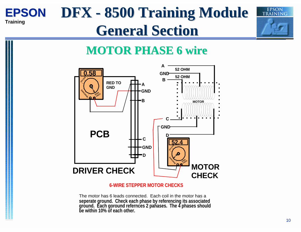
FIVE: (Actual Troubleshooting Process for Printers)Step 1) K.I.S.S. – Don’t Overlook the Obvious!! Do a good visual and verify that power is present. Check the DIP Switch settings. Verify that all fuses are good. Many printer problems are simply attributed to a loose connection, incorrect settings (DIP Switches and Drivers) or even a blown fuse. Look and Listen for proper mechanical movement. Don’t forget, when troubleshooting printers the Power of Observation is your best troubleshooting tool !!
Step 2 ) Divide and Conquer: Determine as Quickly as possible whether your dealing with a Mechanical or Logical problem. This is done by testing the Mechanism first. Check out all Motors, Sensors and also the Printhead, if your dealing with an Impact Printer. If a Bad Motor or Printhead is found, it is Extremely Important to check out its associated Driver Circuit. Failure to do so can cause DAMAGE to the newly replaced part.
Step 3) If the Mechanism checks out good, your problem is with the Logic Board or Program ROM. Under Warranty Conditions, Replace Both. In O.O.W Cases further investigation is required. No Initialization can be caused by many factors, but this is a typical symptom for a bad P-ROM.
Step 4) If you still haven’t fix the Problem, GO BACK TO THE MECHANISM, because you have overlooked Something in your Initial Check.
Step 5) After clearing the problem, perform any required adjustments and perform Preventive Maintenance when necessary. Verify the fix by running a full CTEST on a Impact Printer, or by printing out a High-Resolution Photo for an inkjet printer.
DFX - 8500 Training Module DFX - 8500 Training ModuleGeneral SectionGeneral Section
Epson’s Five and Dime Troubleshooting ProcessEpson’s Five and Dime Troubleshooting Process

15
EPSONEPSONTraining
DFX - 8500 Training Module DFX - 8500 Training ModuleOperational/MechanicalOperational/Mechanical
This section contains Operational and This section contains Operational and Mechanical references to familiarize yourselfMechanical references to familiarize yourselfwith the Operation of the DFX - 8500.with the Operation of the DFX - 8500.
16
EPSONEPSONTraining
DFX - 8500 Training Module DFX - 8500 Training ModuleOperational/MechanicalOperational/Mechanical
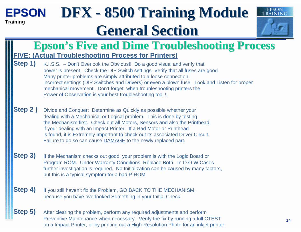
DFX SERIES PRINTERSDFX SERIES PRINTERSDIFFERENCESDIFFERENCES
ITEM 5000 5000+ 8000 8500
AC POWER AUTO-SENS 117 117 117# PINS 9 9 18 18SPEED 533 566 1066 1120PAPER WIDTH NO YES YES YESJAM SENS NO YES NO YESL. HOME YES NO YES NOTIMING CR-ENCODER TMG STRIP CR-ENCODER TMG STRIPTRACTOR Locking Clamp String tension Locking Clamp String tensionBETA CHART NO YES YES YESPRINT FAN YES NO YES YESPGHP SENS NO YES NO YESCR MOT FAN NO NO NO YESRIB MOTION SENS NO NO NO YES

17
EPSONEPSONTraining
Before you begin the operation lab: Read the following to help you understand thepaper loading process.
With paper parked in Front Tractor and the printer set for Front Load, the printer will alwaysfollow this sequence.
1. When the LOAD button is pressed on the Front Panel, the Paper Feed Motor engages the TractorMechanism.
2. The paper advances up until it engages P.E. Sensor. (If the P.E. sensor detects paper installed the PFMotor backs the paper until the PE. Sensor toggles, then advance the paper forward to register the P.E.Sensor.)
3. The paper thickness is checked multiple times without Paper.
4. The paper is then loaded up past the Upper Paper End Sensor.
5. The paper thickness is checked again with paper loaded.
6. The paper bail closes.
DFX - 8500 Training Module DFX - 8500 Training ModuleOperational/MechanicalOperational/Mechanical
DFX-8500 Paper Loading ProcessDFX-8500 Paper Loading Process

18
EPSONEPSONTraining
Continued:7. The paper width is checked.
8. The paper bail opens and the PF motor backs paper down.
9. The paper will back down to its default position (just below P.H.) unless the Top Of Form has beenset from the Front Panel. in which case the Paper will back down to the preset position. (If the PullTractor is installed the paper will feed forward instead of back to the T.O.P)
The Loading Sequence is Exactly the same with Paper Parked in Rear Tractor & the Printer set for Rear Load.
Loading Sequence when Switching from Front load condition to Rear or Visa Versa.
When the Paper Select button on the Front Panel is pushed to switch paper paths:1 . The Ribbon Motor engages the Tractor Select Mechanism until the Tractor Select Sensor toggles.2. The Paper feed Motor engages Tractor Mechanism for the new paper path.3. The paper is advanced until P.E. Sensor is engaged.4. The Loading Sequence then follows the same order as above.
DFX - 8500 Training Module DFX - 8500 Training ModuleOperational/MechanicalOperational/Mechanical
DFX-8500 Paper Loading ProcessDFX-8500 Paper Loading Process

19
EPSONEPSONTraining
PERFORM THE FOLLOWING:
1. INITIAL: Remove any packing material and brackets from under the cover. Remove any paper. Make sure you have a power cord.
2. POWER: Position the print head in the center of the carriage. Power ON. Press LOAD. a. Did you get any beeps? How many? What does it mean? b. Where did the Printhead stop? c. Power OFF and put paper in the tractor. Repeat STEP 2. d. Press LOAD. Now where did the Printhead stop? Power OFF.
3. SELF-TEST: Perform the following Self-Tests. Refer to the User Guide for Switch settings: a. Power ON while holding PAUSE............. (SW Settings print) b. Power ON while holding LF/LOAD....(Rolling ASCII prints)... press PAUSE to stop printing. c. What is the first DATA printed in step a?
4. SMART-PARK: Print a few pages of ASCII then: a. Stop the printer. Tear off paper above the Printhead. b. Press TRACTOR SELECT. c. Did the paper back out? d. Where did it stop?
DFX - 8500 Training Module DFX - 8500 Training ModuleOperational/MechanicalOperational/Mechanical
Operation LabOperation Lab

20
EPSONEPSONTraining
Continued:
5. TRACTOR SELECT: Put paper in both front and rear tractors. Load paper, then:a. Press PAPER SELECT. (Paper path switches to opposite tractor)b. Did the printer do AUTO GAP on the new paper?c. Did the printer search for the right margin again?d. Power OFF and reset all switches to OFF.
6. PIN FIRE: Connect the printer to the computer.a. Go to DOSb. Go to Directory c:\TEST\CTESTc. Type CTEST to start the test.d. Select the 9-PIN group, DFX-8000 printer.e. Select PINFIRE, when prompted enter “A” for all pins.f. Did all 9 pins fire?g. Perform a Confidence test.
7. Lab finished. DO NOT PROCEED TO NEXT LAB YET.
DFX - 8500 Training Module DFX - 8500 Training ModuleOperational/MechanicalOperational/Mechanical
Operation LabOperation Lab

21
EPSONEPSONTraining
PERFORM THE FOLLOWING: REFERENCE PAGE(click)
1. START: Power OFF, unplug AC cord. Remove paper and ribbon
2. SIDES: Remove both side covers................................................................... 3-14
3. OP PANEL: Remove the front (operator) cover.............................................. 3-16
4. UPPER CASE: Remove upper housing (Shroud).......................................... 3-17
5. INTERFACE PLATE: From the rear (8 screws) …......................................... 3-19
6. BOTTOM: Remove bottom logic panel and unplug cables............................. 3-20 (Do not remove assemblies from the bottom panel)
7. INTERLOCK: Remove interlock switch.......................................................... 3-28
8. MECHANISM : 1ST: CLOSE ALL TRACTOR COVERS! Follow procedures in manual to remove the mechanism....... 3-30
(THEN- put pads under the mechanism to protect table)
DFX - 8500 Training Module DFX - 8500 Training ModuleOperational/MechanicalOperational/Mechanical
Mechanical LabMechanical Lab

22
EPSONEPSONTraining
Continued:9. IDENTIFICATION: Locate the following: (Links Below may help identify.)
__ COVER OPEN SWITCH __ INTERLOCK SWITCH__ REAR PAPER OUT SENSOR __ TRACTOR SELECT SENSOR__ JAM SENSOR __ PULL TRACTOR SENSOR__ TIMING BELT SENSOR __ PLATEN GAP SENSOR__ JUNCTION BOARD __ PAPER WIDTH SENSOR__ PLATEN GAP MOTOR __ CARRIAGE MOTOR__ RIBBON MOTION SENSOR __ 15a FUSE
************* STOP - DO NOT PROCEED ************10. JAM SENSOR: Your instructor will remove the BAIL ARM and JAM SENSOR on one unitto demonstrate this procedure....
11. TRACTOR ASSY. Remove either the front/rear tractor assembly. Remove the string fromwithin the tractors. Your instructor will demonstrate how to re-install the wire.
************ WAIT FOR THEORY DISCUSSION ************ JUNCTION BOARD LAYOUT : FUNCTIONAL DIAGRAM
DFX - 8500 Training Module DFX - 8500 Training ModuleOperational/MechanicalOperational/Mechanical
Mechanical LabMechanical Lab

23
EPSONEPSONTraining
Continued:
11. RESISTANCE CHECKS - Using your charts and VOM, perform the following POWER OFF checks:
PRINTHEAD COILS (pin 1 & 7) = ?PRINTHEAD THERMISTOR........ = ?PAPER FEED MOTOR 1ST PHASE.. = ?BAIL ARM SOLENOID........... = ?PG motor 1ST phase.......... = ?CR motor ................... = ?PG HOME SENSOR CHECKPULL TRACTOR SENSOR CHECK
DFX - 8500 Training Module DFX - 8500 Training ModuleOperational/MechanicalOperational/Mechanical
Mechanical LabMechanical Lab

24
EPSONEPSONTraining
Continued:
ADJUSTMENTSReference the DFX-8500 manual section 4 for the following adjustments:
12. BACKLASH: For platen gap adjust motor................................................... 4-1
13. BELT TENSION: Using pull tension gauge (NOTE- review this adjustment, 4-2 but do not perform it on your unit)
14. PARALLELISM : You will need the dial gauge & base. Wait for instructor to 4-8 demo this adjustment first.
15. PREPARE FOR RUNNING: At this point the mechanism and logic assembly can be connected for bench operation. Place the two assemblies side-by-sideand make sure the following is done:
- Cover open is defeated with jumper- Interlock is jumped- All connectors are in place
- One ground strap is connected between assemblies- Mech has paper under it to protect table top
DFX - 8500 Training Module DFX - 8500 Training ModuleOperational/MechanicalOperational/Mechanical
Mechanical LabMechanical Lab

25
EPSONEPSONTraining
Continued: 16. SWITCH CHECKS - Using your reference charts and VOM, check the following:
a. Power supply voltage checks. (5 & 35VDC)b. Remaining POWER ON checks from the charts located in the troubleshooting
section:- Front paper out SENSOR
- Rear paper out SENSOR-Top paper out SENSOR- Ribbon Motion Sensor- Paper Width SENSOR
17. BETA ADJUSTMENTThe adjustments in the ADJUSTMENT CHART, located in the adjustment section, will be performed by your instructor first, then you will perform the same adjustments on your machine using the special chart provided. 18. CLEAN UP- Clean up around your area:
- Remove paper from the Printer- UNPLUG the AC cord from the Printer- Discard used paper- Discard any trash, paper cups, cans, etc.
Troubleshooting: Follow the OBSERVATION SEQUENCE steps located in the Troubleshooting Section of this guide. (makes troubleshooting EASY)
DFX - 8500 Training Module DFX - 8500 Training ModuleOperational/MechanicalOperational/Mechanical
Mechanical LabMechanical Lab
26
EPSONEPSONTraining
DFX - 8500 Training Module DFX - 8500 Training ModuleTroubleshooting / Test PointsTroubleshooting / Test Points
The Troubleshooting / Test points section The Troubleshooting / Test points section contains various documents to assist you in the contains various documents to assist you in the troubleshooting process. Refer closely to thetroubleshooting process. Refer closely to the Observation SequenceObservation Sequence and and Flow ChartsFlow Charts..
27
EPSONEPSONTraining
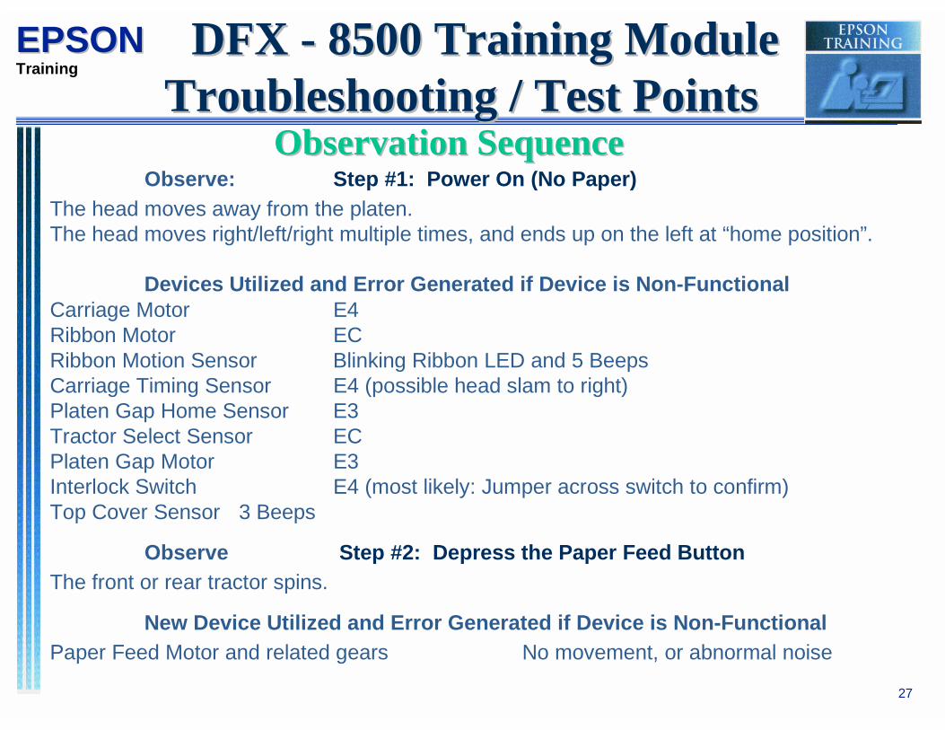
Observe: Step #1: Power On (No Paper)
The head moves away from the platen.The head moves right/left/right multiple times, and ends up on the left at “home position”.
Devices Utilized and Error Generated if Device is Non-FunctionalCarriage Motor E4Ribbon Motor ECRibbon Motion Sensor Blinking Ribbon LED and 5 BeepsCarriage Timing Sensor E4 (possible head slam to right)Platen Gap Home Sensor E3Tractor Select Sensor ECPlaten Gap Motor E3Interlock Switch E4 (most likely: Jumper across switch to confirm)Top Cover Sensor 3 Beeps
Observe Step #2: Depress the Paper Feed Button
The front or rear tractor spins.
New Device Utilized and Error Generated if Device is Non-Functional
Paper Feed Motor and related gears No movement, or abnormal noise
DFX - 8500 Training Module DFX - 8500 Training ModuleTroubleshooting / Test PointsTroubleshooting / Test Points
Observation SequenceObservation Sequence
28
EPSONEPSONTraining
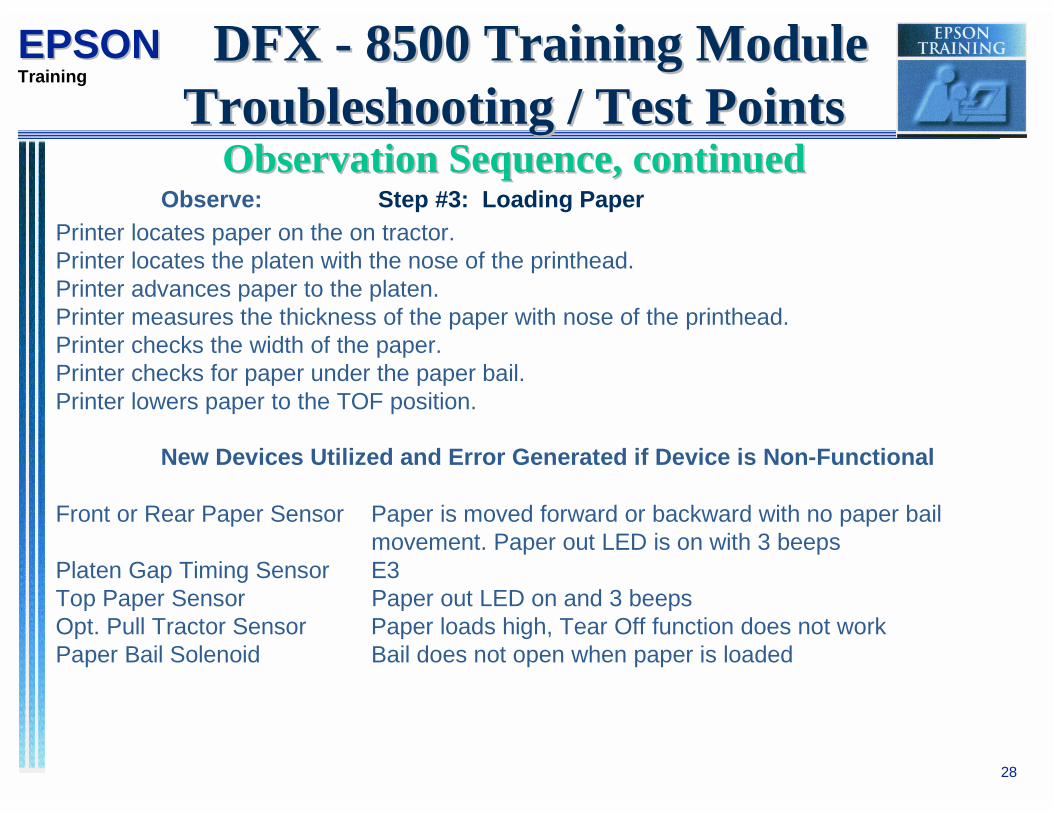
Observe: Step #3: Loading Paper
Printer locates paper on the on tractor.Printer locates the platen with the nose of the printhead.Printer advances paper to the platen.Printer measures the thickness of the paper with nose of the printhead.Printer checks the width of the paper.Printer checks for paper under the paper bail.Printer lowers paper to the TOF position.
New Devices Utilized and Error Generated if Device is Non-Functional
Front or Rear Paper Sensor Paper is moved forward or backward with no paper bail movement. Paper out LED is on with 3 beeps
Platen Gap Timing Sensor E3Top Paper Sensor Paper out LED on and 3 beepsOpt. Pull Tractor Sensor Paper loads high, Tear Off function does not workPaper Bail Solenoid Bail does not open when paper is loaded
DFX - 8500 Training Module DFX - 8500 Training ModuleTroubleshooting / Test PointsTroubleshooting / Test Points
Observation Sequence, continuedObservation Sequence, continued
29
EPSONEPSONTraining
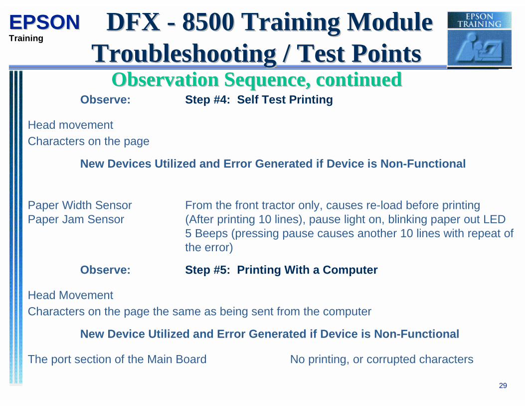
Observe: Step #4: Self Test Printing
Head movement
Characters on the page
New Devices Utilized and Error Generated if Device is Non-Functional
Paper Width Sensor From the front tractor only, causes re-load before printingPaper Jam Sensor (After printing 10 lines), pause light on, blinking paper out LED
5 Beeps (pressing pause causes another 10 lines with repeat ofthe error)
Observe: Step #5: Printing With a Computer
Head Movement
Characters on the page the same as being sent from the computer
New Device Utilized and Error Generated if Device is Non-Functional
The port section of the Main Board No printing, or corrupted characters
DFX - 8500 Training Module DFX - 8500 Training ModuleTroubleshooting / Test PointsTroubleshooting / Test Points
Observation Sequence, continuedObservation Sequence, continued

30
EPSONEPSONTraining
Things That Could Cause Failure Once Printing
Devices and Errors Generated
Top Cover Sensor Stops printing, No error code, Pause light onFront or Rear Paper Sensor Paper out LED on and 3 beepsPaper Jam Sensor (After printing 10 lines), pause light on, blinking paper out LED
5 Beeps (pressing pause causes another 10 lines with repeat ofthe error)
Ribbon Motor Blinking ribbon LED, 5 BeepsRibbon Motion Sensor Blinking ribbon LED, 5 BeepsRear Interlock Sensor E4Carriage Timing Sensor E4 (Head may slam)Tractor Select Sensor Paper out LED on and 3 beepsCarriage Motor E4
DFX - 8500 Training Module DFX - 8500 Training ModuleTroubleshooting / Test PointsTroubleshooting / Test Points
Observation Sequence, continuedObservation Sequence, continued

31
EPSONEPSONTraining
(DFX Power-Up Initialization Sequence)
1) 5VDC and 35VDC is generated
2) Case Open Sensor is checked
3) Platen Gap Motor movement
4) Platen Gap H.P. is checked
5) Interlock Switch is checked (generates carriage error if case open sensor closed).
6) Carriage Drive
7) Carriage Encoder or H.P. Sensor is checked
8) Ribbon Feed Motor movement
9) Tractor Select Mechanism is checked for Front or Rear tractors
10) Paper IN or Out detected.
( The Power of OBSERVATION is your best Troubleshooting Tool!)
DFX - 8500 Training Module DFX - 8500 Training ModuleTroubleshooting / Test PointsTroubleshooting / Test Points
Check 10 Devices in 10 SecondsCheck 10 Devices in 10 Seconds

32
EPSONEPSONTraining
1) Paper Bail Opens 12) Opens Paper Bail
2) Backs Paper Out 13) Centers print head
3) Closes Paper Bail 14) Paper Bail closes when Upper PE detects paper.
4) Paper Width seek without paper
5) Multiple paper thickness check without paper
6) Centers print head
7) Opens Paper Bail
8) Loads paper
9) Multiple paper thickness checks with paper
10) Closes Paper Bail
11) Paper Width seek with paper
DFX - 8500 Training Module DFX - 8500 Training ModuleTroubleshooting / Test PointsTroubleshooting / Test Points
DFX - 5000+ and DFX - 8000DFX - 5000+ and DFX - 8000Loading/Unloading SequenceLoading/Unloading Sequence
33
EPSONEPSONTraining
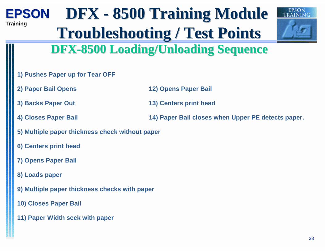
1) Pushes Paper up for Tear OFF
2) Paper Bail Opens 12) Opens Paper Bail
3) Backs Paper Out 13) Centers print head
4) Closes Paper Bail 14) Paper Bail closes when Upper PE detects paper.
5) Multiple paper thickness check without paper
6) Centers print head
7) Opens Paper Bail
8) Loads paper
9) Multiple paper thickness checks with paper
10) Closes Paper Bail
11) Paper Width seek with paper
DFX - 8500 Training Module DFX - 8500 Training ModuleTroubleshooting / Test PointsTroubleshooting / Test Points
DFX-8500 Loading/Unloading SequenceDFX-8500 Loading/Unloading Sequence

EPSON® Service Training Document
Subject: DFX-8500 Sensor / Motor / Print Head / Driver Test PointsCreated By: Ray Balli, Bob BohnDocument #: RB-092000-00
34
Refer to Junction Board Layout for pin number location if necessarySENSOR NAME POWER METER LEAD 1 COMMON ACTION METER READING
Paper Width ON PIN 1 (BLUE) ONConn behind PH
PIN 2(BLACK)
INSERT AND REMOVE PAPER FROMSENSOR NEXT TO PRINTHEAD
TOGGLES BETWEEN 0 AND 1VDC
Carriage TimingSensor
ON PIN 3,4 (CN 4)ON MAIN
PIN 1 MOVE PH, SLOWLY, LEFT TO RIGHT TOGGLES BETWEEN 0 AND 5VDC
Rear Paper Out ON PIN 2 (CNG) PIN 1 PRESS & RELEASE LEVER ONTRACTOR
TOGGLES 0-5VDC
Front Paper Out ON PIN 2 (CN F) PIN 1 PRESS & RELEASE LEVER ONTRACTOR
TOGGLES 0-5VDC
Upper Paper EndSensor
ON PIN 2 (CN H) PIN 1 SENSOR LOCATED IN PAPER BAIL BARRAISE & LOWER BAIL ARM
TOGGLES 0-5VDC
Jam Sensor*2nd method
ON*OFF
PIN 1 (CN E)*PIN 2 (+Lead)
PIN 2,3*P,1,3(-Ld)
TURN ROLLER AT COLUMN 5*(Diode Check),Test Cable unplugged
TOGGLES 0-5VDC* Consistent readings (.6) +/- 20%
Platen GapThickness Sensor
ON PIN 2,3 (CN I) PIN 1 SLOWLY ROTATE CR RAIL TOGGLES 0-5VDC
Platen Gap HomePosition Sensor
OFF PIN 1 (CN M) PIN 2 ROTATE CR RAIL FORWARD TOSTOP
TOGGLES SHORT AND OPEN
Interlock Switch OFF PIN 1 (CN N) PIN 2 TOGGLE INTERLOCK SW TOGGLES SHORT AND OPEN
Pull TractorSensor
OFF PIN 1 (CN D) PIN 2 TOGGLE SW BEHIND SOLENOID TOGGLES SHORT AND OPEN
Tractor SelectSwitch
OFF PIN 1 (CN L) PIN 2 ROTATE RIB DR GEAR TO TOGGLESENSOR SW
TOGGLES SHORT AND OPEN
Ribbon MotionSensor
ON PIN 4 (CN O) PIN 2 Rotate Ribbon Drive gear 0-5 VDC
**Remember to unplug cover open with Power On Checks.*** Test method used to isolate the Jam sensor cable or CN E on the junction board.

EPSON® Service Training Document
Subject: DFX-8500 Sensor / Motor / Print Head / Driver Test PointsCreated By: Ray Balli, Bob BohnDocument #: RB-092000-00
35
Refer to Junction Board Layout and Printhead Cable layout for below test points
Motor/Coil POWER METER LEAD 1 COMMON ACTION METER READING
Bail ArmSolenoid
OFF PIN 1 (CN C) PIN 2 Set Meter to OhmsRange 2K or Leas
9 Ohms (+/- 10%)
CarriageMotor
OFF PIN 1 (CN B) PIN 1 Same as above 2 Ohms (+/- 10%)
Paper FeedMotor
OFF PIN 1 (CN A) PIN 1 Same as above 3 Ohms (+/- 10%)
MechanismFan
OFF PIN 1 (CN R) PIN 1 Same as above No Reading,Brushless Motor**
CarriageMotor Fan
OFF PIN 1 (CN P) PIN 1 Same as above No Reading,Brushless Motor**
Platen GapMotor
OFF PIN 1 (CN J) PIN 2,3 Same as above 245 Ohms (+/- 10%)
Ribbon FeedMotor
OFF PIN 1 (CN K) PIN 1 Same as above 148 Ohms (+/- 10%)
Printhead PinCoils
OFF Printhead cable Refer to Printhead Cable Layout 3 Ohms (+/- 10%)
PrintheadThermistor
OFF Printhead cable Refer to Printhead Cable Layout 10K Ohms (+/- 10%)
PrintheadFan
OFF Printhead cable Refer to Printhead Cable Layout 61 Ohms (+/- 10%)
Printhead FanThermistor
OFF Printhead cable Refer to Printhead Cable Layout 50K Ohms (+/- 10%)
**With Brushless Fans, with power applied, if fan spins its good.**

EPSON® Service Training Document
Subject: DFX-8500 Sensor / Motor / Print Head / Driver Test PointsCreated By: Ray Balli, Bob BohnDocument #: RB-092000-00
36
DEVICE POWER TP#1 TP#2 REQUIRED ACTION METER READINGSet to DIODE CHECK
Printhead DriversDriver Brd. B Qf2-Qf18 (even)
OFF PIN 2(DRAIN)
PIN 3(SOURCE)
Put Negative Lead on TP#1 andPositive Lead on TP#2
Consistent readings within +/- 20%(.535)
Printhead DriversDriver Brd. B Qf1-Qf17(odd)
OFF PIN 2(DRAIN)
PIN 3(SOURCE)
Put Positive Lead on TP#1 andNegative Lead on TP#2
Consistent readingswithin +/- 20%(.535)
Printhead DriversMain Board Qf2-Qf18 (even)
OFF PIN 2(DRAIN)
PIN 3(SOURCE)
Put Negative Lead on TP#1 andPositive Lead on TP#2
Consistent readingswithin +/- 20%(.535)
Printhead DriversMain Board Qf1-Qf17(odd)
OFF PIN 2(DRAIN)
PIN 3(SOURCE)
Put Positive Lead on TP#1 andNegative Lead on TP#2
Consistent readingswithin +/- 20%(.535)
Carrige Motor DriversDriver Brd.A (IC1)
OFF PIN 8 PIN6,7,10,11
Put Negative Lead on TP#1 andPositive Lead on TP#2
Consistent readingswithin +/- 20%(.505)
Paper Feed DriversDriver Brd. A (IC2)
OFF PIN 4 PIN2,3,6,7
Put Positive Lead on TP#1 andNegative Lead on TP#2
Consistent readingswithin +/- 20%(.510)
Platen Gap Motor Drv'sQ12,13,14,15
OFF Emitter orGND
Center Pin Put Positive Lead on TP#1 andNegative Lead on TP#2
Consistent readingswithin +/- 20%(.707)
Ribbon Feed Motor Drv's -Q22,23,24,25
OFF Emitter orGND
Center Pin Put Positive Lead on TP#1 andNegative Lead on TP#2
Consistent readingswithin +/- 20%(.707)
Platen Gap Motor Common DriverQ11
OFF Emitter orGND
Center Pin Put Negative Lead on TP#1 andPositive Lead on TP#2
Consistent readings within +/-20% Base(.722), Emitter(.618)
Ribbon Feed Motor Common DriverQ21
OFF Both outsidePINS
Center Pin Put Negative Lead on TP#1 andPositive Lead on TP#2
Consistent readings within +/-20% Base(.722), Emitter(.618)
Paper Bail Solenoid DriverQ31
OFF Both outsidePINS
Center Pin Put Negative Lead on TP#1 andPositive Lead on TP#2
Consistent readings within +/-20% Base(.660), Emitter(.586)
Carriage Fan DriverQ33
Both outsidePINS
Center Pin Put Negative Lead on TP#1 andPositive Lead on TP#2
Consistent readings within +/-20% Base(.664), Emitter(.599)
Print Head Fan Drivers Q10 , Q11 OFF Both outsidePINS
Center Pin Put Negative Lead on TP#1 andPositive Lead on TP#2
Consistent readings within +/-20% Base(.680), Emitter(.583)
Eps
on A
mer
ica,
Inc.
T
echn
ical
Doc
umen
t
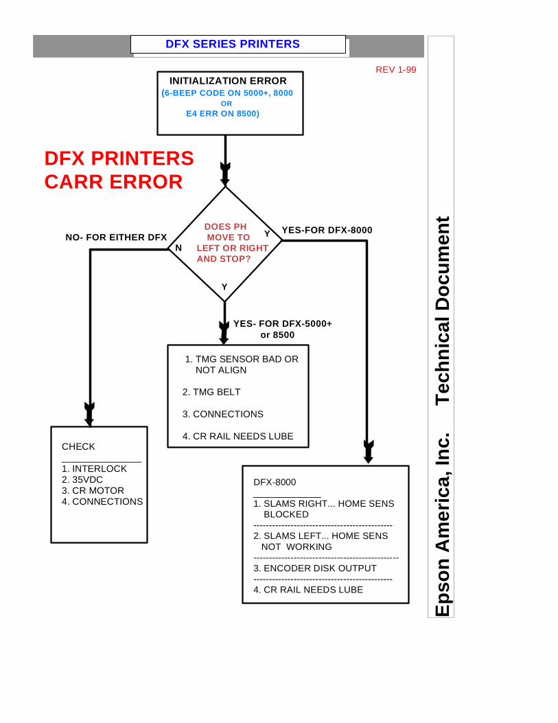
DFX PRINTERSCARR ERROR
INITIALIZATION ERROR(6-BEEP CODE ON 5000+, 8000 OR E4 ERR ON 8500)
DOES PH MOVE TO LEFT OR RIGHTAND STOP?
CHECK_______________1. INTERLOCK2. 35VDC3. CR MOTOR4. CONNECTIONS
DFX-8000_____________1. SLAMS RIGHT... HOME SENS BLOCKED---------------------------------------------2. SLAMS LEFT... HOME SENS NOT WORKING-----------------------------------------------3. ENCODER DISK OUTPUT---------------------------------------------4. CR RAIL NEEDS LUBE
1. TMG SENSOR BAD OR NOT ALIGN
2. TMG BELT
3. CONNECTIONS
4. CR RAIL NEEDS LUBE
YES-FOR DFX-8000
YES- FOR DFX-5000+ or 8500
NO- FOR EITHER DFXN
Y
Y
REV 1-99
DFX SERIES PRINTERS

38
EPSONEPSONTraining
On the DFX Series printers, most of the errors can be determined by performing the testpoints. Refer to the Functional Diagram, Junction Board layout and Test point Chartslocated in this module by clicking the above links.When performing test points, if a motor, solenoid or print head are found to be faulty,ALWAYS check the corresponding DRIVERS on the main/driver board. (Diode check)
The 5 most common errors that may occur are the following:1) Carriage errors -- (indicated by 6 beeps or an E4 error on the DFX-8500)2) Sensor errors - (several different symptoms)3) Errors that may require an adjustments4) Motor / Mechanical failure5) Paper Handling problems
Topic: Carriage Errors
** Never overlook the following: ***** Interlock switch ***** Home position sensor **ConnectionsCarriage motorPrint head dampersDFX5000+ and DFX-8500 Encoder Strip (Timing Fence)The Paper Width or Carriage Encoder sensors usually cause intermittent errors. (Note:still check all the above.)
Topic: No Error Codes
(1) Symptom: Lights ON/OFF, no functions (Brain dead).Possible Solutions: Parallel port may be shorting to GND. Unplug cable from computer.Check wiring harness connectionsDefective/missing P-ROMDefective Main board (check voltages on power supply).(Note: if DFX-5000+, unplug from outlet and wait for 5 min. before turning the printer back on).
DFX - 8500 Training Module DFX - 8500 Training ModuleTroubleshooting / Test PointsTroubleshooting / Test Points
DFX-Series Common SymptomsDFX-Series Common Symptoms

39
EPSONEPSONTraining
Topic: Sensor Errors** Note: there are 4 standard sensor types that are used in Epson Printers as follows:Magnetic (Hall Effect), Mechanical, Thermal (thermistor), and Photo (optical).
(1) Sensor: Home Position (H.P. Sensor) (Photo) (DFX-5000, DFX-8000)Error indicated: CARRIAGE ERROR. The print head may slam to one end of the mechanism, the print head may move in the opposite direction (awayfrom home) or not move at all.Action (Photo): Paper particles/dust could block this sensor. Clean the sensor. Check the sensor using a voltmeter.
(2) Sensor: Thermister (Thermal)Error indicated: The thermistor is mounted inside of the print head. The thermistor monitors the temperature of theprint head. If the sensor reports excessive heat, it may do one or all of the following:1. Stop and Start printing (suspend printing).2. Reduce Print Speed.3. Move print head without printing.4. Turn on a Print Head fan.5. Any combination of the above.If none of these actions cool down the print head, the printer will shut down and might give athermistor error.Action: Check the resistance of thethermistor @ room temperature. Cup the print head in your hand for about aminute and take another reading. Depending on the type of thermistor, thereading should go up or down. Ifthe reading doesn't change, replace the print head.
(3) Sensor: Paper Width (PW Sensor) (Photo)Error indicated: The Paper Width Sensor detects the width of the paper to prevent printing on the platen. The Paper Width Sensor will fail one of twoways. It will either report that the width of the paper is the entire width of the platen or that the paper width is zero (not there). If it thinks the paper width isthe entire width of the platen, it will print on the platen if the paper is less than 14 7/8 inches wide. If it doesn’t see paper at all it may assume the leftmargin is 0 and the right margin is 0 (LQ-2550). The printer might just feed paper through without printing. With the DFX Series, a 3-beep error codemight be generated, indicating an incomplete paper exit. When attempting to put the printer On-Line (Ready), the print head might scan the platen areatrying to register the paper width but will not go On-Line (Ready).
Action: Because the PW Sensor is located on the ribbon mask, it can get a buildup of ribbon fiber and/or ink. Paperdust, stuck labels and glue residue from labels are quite common. Remove the sensor and clean both thesensor and the Ribbon Mask Holder. Check the sensor with voltmeter.
DFX - 8500 Training Module DFX - 8500 Training ModuleTroubleshooting / Test PointsTroubleshooting / Test Pointscontinued

40
EPSONEPSONTraining
DFX - 8500 Training Module DFX - 8500 Training ModuleTroubleshooting / Test PointsTroubleshooting / Test Points
Topic: Sensor Errors cont’d:
(4) Sensor: Carriage Belt Encoder (Photo) (DFX-5000+, DFX-8500)Error Indicated: This sensor reports to the logic where the print head carrier is at all times. If the Encoder Strip or sensor gets damaged or dirty,it could cause a Carriage Error, show up on the print out as erratic print margins or cause inconsistent character spacing (i.e. prints 1/2 of a line,skips about 1/4 of the line then continues to print the last part of the line. The DFX-5000+ will produce an audible error code of 2 sets of 3 beepstotalling 6 beeps. The DFX-8500 will give an error code on the 7-segment LED display. If a ribbon jam or paper jam occurs, the timing fence (encoder strip) may get mis-aligned while removing any obstruction. The timing fence should lay flat ¼” above the bottom of the mechanismand should pass through the middle of the sensor.Action: Clean the timing fence (encoder strip) with a soft cloth. Clean the sensor. Check the positioning of the timing fence. Check the sensorwith a voltmeter. The reading should toggle between 0v-5v.
(5) Sensor: Carriage Motor Encoder (Photo) (DFX-5000, DFX-8000)Error Indicated: This sensor’s function is similar to #4. The sensor usually causes a carriage error (6 sets of 3 beeps =18 beeps total).It could also cause incorrect margins.Action: The sensor is embedded inside the carriage motor. Test the sensor with a voltmeter. The reading should toggle between 0v-5v.If it doesn’t toggle, check the connections before replacing the carriage motor.
(6) Sensor: Rear/Front Paper End (Rear/Front PE) (Photo)Error Indicated: This sensor indicates whether or not paper is loaded on the tractor assemblies. When the sensor fails, it will cause a paperrelated error to be generated. When loading paper into the currently selected paper path, a “Paper Out” error will be generated. When changingpaper paths, either a “Paper Out” error or “Other Paper Error” (indicated by 3 beeps) will be generated.Action: Ensure that the sensors toggle easily when manually depressed and that the actuator makes proper contact with the paper.Check for jammed paper and labels in the tractor. Test the sensor with a voltmeter. The reading should toggle between 0v-5v.
(7) Sensor: Platen Gap Home Position (PG HP Sensor) (Mechanical) (DFX-5000+, DFX-8500)Error Indicated: This sensor informs the logic that the print head is at its reference point (maximum gap setting). A grinding noise along witha Carriage Error or Platen Gap error will occur if the sensor is faulty. If the printer is not powered off within 5 seconds for the DFX-5000+or 12 seconds for the DFX-8500, the printer will shut down the power supply. To restore power, the printer must be turned off and theAC cable unplugged from the printer for 5 minutes.Action: Test the sensor with an ohmmeter. The sensor should toggle between open - short.
continued
41
EPSONEPSONTraining
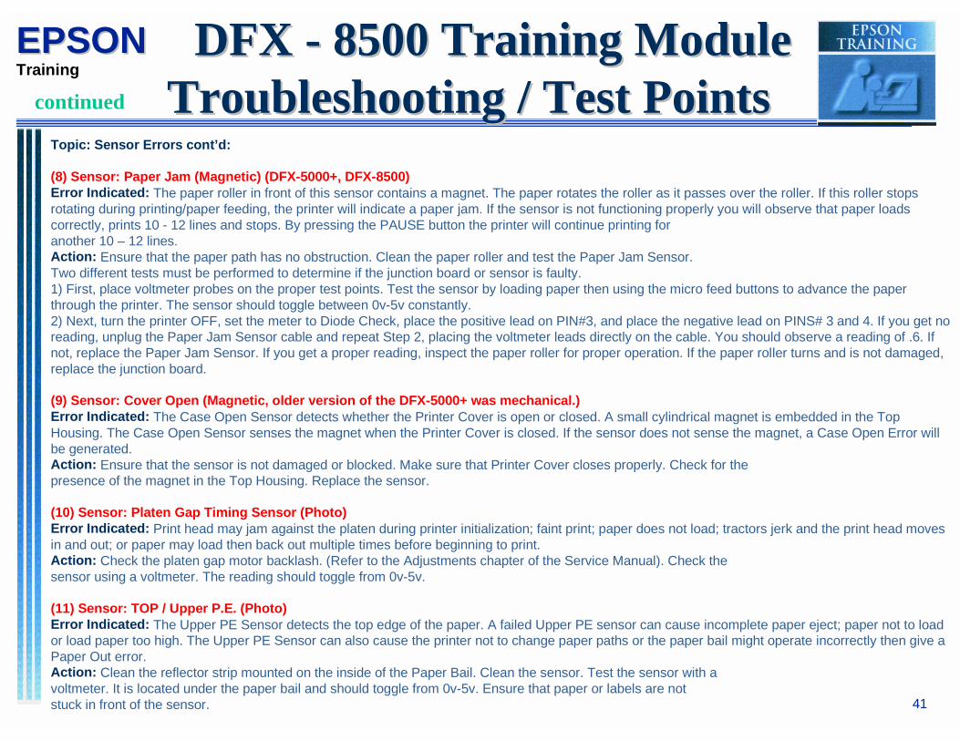
Topic: Sensor Errors cont’d:
(8) Sensor: Paper Jam (Magnetic) (DFX-5000+, DFX-8500)Error Indicated: The paper roller in front of this sensor contains a magnet. The paper rotates the roller as it passes over the roller. If this roller stopsrotating during printing/paper feeding, the printer will indicate a paper jam. If the sensor is not functioning properly you will observe that paper loadscorrectly, prints 10 - 12 lines and stops. By pressing the PAUSE button the printer will continue printing foranother 10 – 12 lines.Action: Ensure that the paper path has no obstruction. Clean the paper roller and test the Paper Jam Sensor.Two different tests must be performed to determine if the junction board or sensor is faulty.1) First, place voltmeter probes on the proper test points. Test the sensor by loading paper then using the micro feed buttons to advance the paperthrough the printer. The sensor should toggle between 0v-5v constantly.2) Next, turn the printer OFF, set the meter to Diode Check, place the positive lead on PIN#3, and place the negative lead on PINS# 3 and 4. If you get noreading, unplug the Paper Jam Sensor cable and repeat Step 2, placing the voltmeter leads directly on the cable. You should observe a reading of .6. Ifnot, replace the Paper Jam Sensor. If you get a proper reading, inspect the paper roller for proper operation. If the paper roller turns and is not damaged,replace the junction board.
(9) Sensor: Cover Open (Magnetic, older version of the DFX-5000+ was mechanical.)Error Indicated: The Case Open Sensor detects whether the Printer Cover is open or closed. A small cylindrical magnet is embedded in the TopHousing. The Case Open Sensor senses the magnet when the Printer Cover is closed. If the sensor does not sense the magnet, a Case Open Error willbe generated.Action: Ensure that the sensor is not damaged or blocked. Make sure that Printer Cover closes properly. Check for thepresence of the magnet in the Top Housing. Replace the sensor.
(10) Sensor: Platen Gap Timing Sensor (Photo)Error Indicated: Print head may jam against the platen during printer initialization; faint print; paper does not load; tractors jerk and the print head movesin and out; or paper may load then back out multiple times before beginning to print.Action: Check the platen gap motor backlash. (Refer to the Adjustments chapter of the Service Manual). Check thesensor using a voltmeter. The reading should toggle from 0v-5v.
(11) Sensor: TOP / Upper P.E. (Photo)Error Indicated: The Upper PE Sensor detects the top edge of the paper. A failed Upper PE sensor can cause incomplete paper eject; paper not to loador load paper too high. The Upper PE Sensor can also cause the printer not to change paper paths or the paper bail might operate incorrectly then give aPaper Out error.Action: Clean the reflector strip mounted on the inside of the Paper Bail. Clean the sensor. Test the sensor with avoltmeter. It is located under the paper bail and should toggle from 0v-5v. Ensure that paper or labels are notstuck in front of the sensor.
DFX - 8500 Training Module DFX - 8500 Training ModuleTroubleshooting / Test PointsTroubleshooting / Test Pointscontinued

42
EPSONEPSONTraining
(12) Sensor: Pull Tractor (Mechanical)Error Indication: The Pull Tractor Sensor detects whether or not an optional Pull Tractor is installed. If the printer thinks the pull tractor is installed whenit is not, the following symptoms would occur:1. Tear-off feature will not work.2. Top of Form seems irregular.If the Tractor is installed and the tear-off feature operates correctly, the sensor is not working.Action: Ensure that the sensor toggles easily. Check the sensor with an ohmmeter. The reading should togglebetween open – shorted.
(13) Sensor: Tractor Select (Mechanical)Error Indicated: The Tractor Select Sensor tells the printer which set of tractors the paper feed gears will drive. If the sensor fails either the printer won’tload paper or it won’t switch between the front and rear tractors.Action: Ensure proper actuator arm movement. Test the sensor with an ohmmeter. The reading should toggle between open – shorted.
(14) Sensor: Interlock Switch (Mechanical)Error Indicated: The interlock switch cuts power to the carriage motor when the Printer Cover is open. If the switch arm is bent or the switch mountingbracket is bent or skewed, the switch will not close properly. The DFX-5000 will print very slowly without giving an error. The DFX-5000+, DFX-8000, andDFX-8500 printers will indicate a Carriage Error!Action: Make sure that the cover closes properly, the arm on the switch is not bent, and the switch mounting bracket isnot skewed. Remove the left side panel and jumper across the Interlock Switch. If the printer operatescorrectly with the Interlock Switch jumpered, replace the Interlock Switch.
Topic: Problems That Might Require an Adjustment
(1) Symptom: When using tractor fed paper, paper jams intermittently.Possible Cause: (a) Tractors are out of phase.(b) Tractors are mis-aligned (belt slipped).Solution: (a) Re-phase the tractors.(b) Replace both tractors.
(2) Symptom: P/H jams up, inconsistent margins, won’t load paper (constant carriage errors)Possible Cause: (a) Print head carrier assembly may be dirty or obstructed.(b) Loose timing belt.(c) Platen Gap Motor backlash may be incorrect.Solution: (a) Clean and lubricate the carriage guide shaft(b) Adjust Timing Belt tension(c) Perform Platen Gap Motor Backlash adjustment
DFX - 8500 Training Module DFX - 8500 Training ModuleTroubleshooting / Test PointsTroubleshooting / Test Pointscontinued

43
EPSONEPSONTraining
(3) Symptom: Characters MisalignedPossible Cause: (a) Bi-directional printing is not working properly.(b) Print head carrier assembly may be dirty or obstructed.Solution: (a) Perform Bi-di. Adjustment (temporary fix is set printer to unidirectional print)(b) Clean and lubricate the carriage guide shaft
(4) Symptom: Faint print / top or bottom of characters missingPossible Cause: (a) Ribbon mask could be damaged or out of place.(b) Platen gap may be to close or too far away from the platen.Solution: (a) Re-install ribbon mask or replace.(b) Adjust platen gap values. (Refer to adjustments, i.e. beta alpha.)
(5) Symptom: Prints faint on one side of the page.Possible Cause: (a) Carriage Guide Shaft is misaligned.Solution: (a) Perform Parallelism adjustment.
Topic: Motor/Mechanical Problems
(1) Symptom: Print Head moves slowly or stops (gives carriage errors).Possible Cause: Dirty Carriage Guide Shaft.Possible Solution: Clean the Carriage Guide Shaft using O-2 oil. Note: Do NOT use “3 in 1” oil, WD-40, etc.
(2) Symptom: Inconsistent Line Feeds. (Grinding noise when performing paper feeds)Possible Cause: (a) Broken Gears(b) Defective L.F. MotorPossible Solution: (a) Replace damaged gears(b) Test L.F. motor with an ohmmeter. Rotate LF motor by hand feeling for abnormally stiffmovement. (NOTE: BEFORE replacing the motor, be sure to check its drivers.)
(3) Symptom: Ribbon not turning (faint print)Possible Cause: (a) Defective ribbon.(b) Damaged ribbon drive assembly.(c) Platen gap too close (will cause ribbon smears on paper).Possible Solution: (a) Replace Ribbon(b) Replace Ribbon Drive Assembly.(c) Adjust Platen Gap (Alpha and Beta values)
DFX - 8500 Training Module DFX - 8500 Training ModuleTroubleshooting / Test PointsTroubleshooting / Test Pointscontinued

44
EPSONEPSONTraining
(4) Symptom: Print Head jams Against PlatenPossible Cause: (1) Damaged Ribbon(2) Parallelism could be out, (if printer was moved or shipped)(3) Platen gap could be to close.Solution: (1) Replace Ribbon(2) Perform parallelism adjustment(3) Adjust platen gap. (Auto)
Possible Cause: (1) Obstruction in mechanism(2) Dirty carrier shaft.(3) Loose timing belt.Solution: (1) Perform Preventative maintenance.(2) Perform Preventative maintenance.(3) Adjust belt.
(6) Symptom: Print Head movement erratic, margins incorrect.Solution: Check carriage motor. Check Carriage Motor drivers. Check Timing Fence if DFX-5000+ or DFX-8500)
(7) Symptom: Prints faint, grinds when adjusting the print head gap (auto)Solution: Check gapping mechanism (motor, gears, sensors and drivers).
(8) Symptom: Paper feeds in and out intermittently (DFX-5000)Solution: Check gapping mechanism (gears [broken/lubrication needed], motor, drivers and sensors).
(9) Symptom: When loading paper, tractors just jerk, will not load.Solution: Check gapping mechanism (Sensors, motor, gears etc.).
(10) Symptom: Print Head constantly over-heating.Solution: Check print head mechanism (fan, thermistor, coils, and drivers).
** NOTE: ALWAYS CHECK GEARS & MANUALLY ROTATE MOTORS WITH POWER OFF. **** BEFORE REPLACING MOTORS, ALWAYS CHECK DRIVERS ON THE MAIN BOARD! **
DFX - 8500 Training Module DFX - 8500 Training ModuleTroubleshooting / Test PointsTroubleshooting / Test Pointscontinued
45
EPSONEPSONTraining
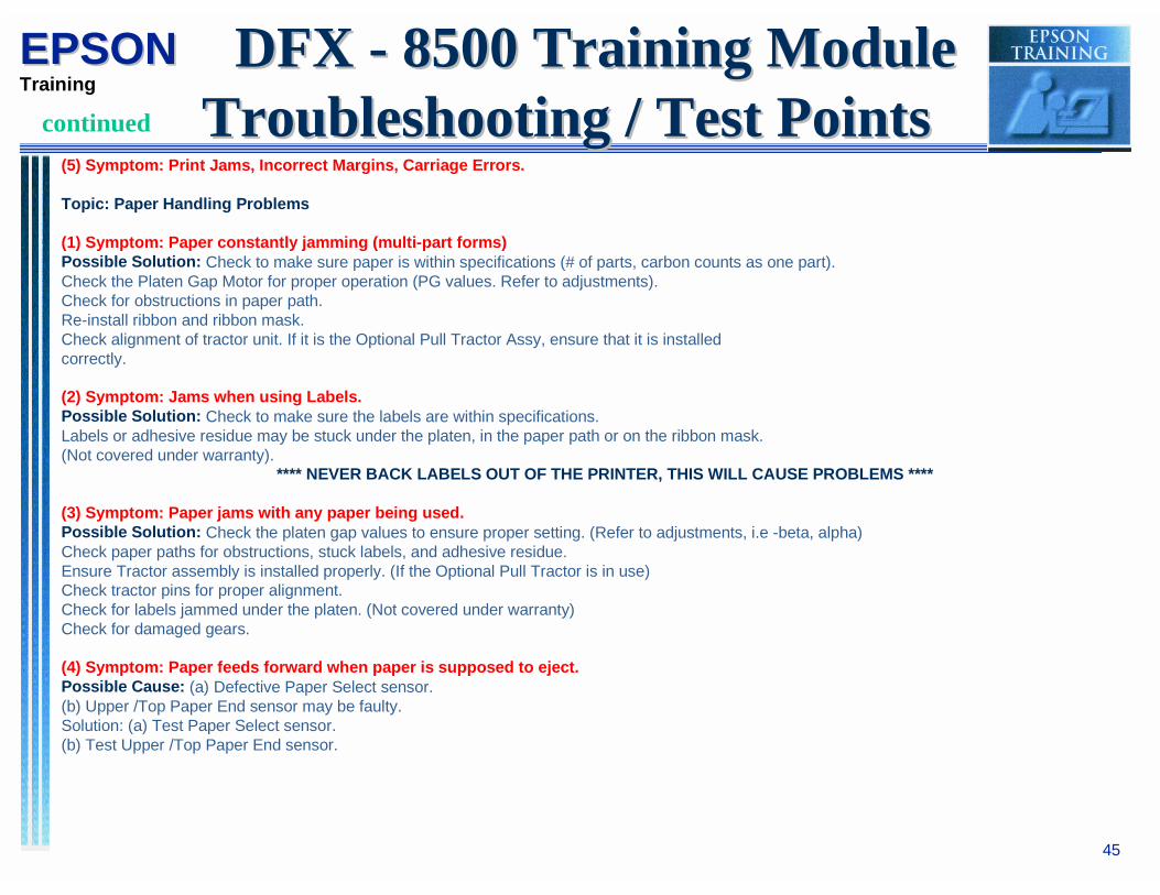
(5) Symptom: Print Jams, Incorrect Margins, Carriage Errors.
Topic: Paper Handling Problems
(1) Symptom: Paper constantly jamming (multi-part forms)Possible Solution: Check to make sure paper is within specifications (# of parts, carbon counts as one part).Check the Platen Gap Motor for proper operation (PG values. Refer to adjustments).Check for obstructions in paper path.Re-install ribbon and ribbon mask.Check alignment of tractor unit. If it is the Optional Pull Tractor Assy, ensure that it is installedcorrectly.
(2) Symptom: Jams when using Labels.Possible Solution: Check to make sure the labels are within specifications.Labels or adhesive residue may be stuck under the platen, in the paper path or on the ribbon mask.(Not covered under warranty).
**** NEVER BACK LABELS OUT OF THE PRINTER, THIS WILL CAUSE PROBLEMS ****
(3) Symptom: Paper jams with any paper being used.Possible Solution: Check the platen gap values to ensure proper setting. (Refer to adjustments, i.e -beta, alpha)Check paper paths for obstructions, stuck labels, and adhesive residue.Ensure Tractor assembly is installed properly. (If the Optional Pull Tractor is in use)Check tractor pins for proper alignment.Check for labels jammed under the platen. (Not covered under warranty)Check for damaged gears.
(4) Symptom: Paper feeds forward when paper is supposed to eject.Possible Cause: (a) Defective Paper Select sensor.(b) Upper /Top Paper End sensor may be faulty.Solution: (a) Test Paper Select sensor.(b) Test Upper /Top Paper End sensor.
DFX - 8500 Training Module DFX - 8500 Training ModuleTroubleshooting / Test PointsTroubleshooting / Test Pointscontinued

46
EPSONEPSONTraining
DFX - 8500 Training Module DFX - 8500 Training ModuleAdjustment SectionAdjustment Section
The Adjustment Section contains supplementsThe Adjustment Section contains supplementsto the Service Manual to further assist youto the Service Manual to further assist youwhile adjusting the DFX - 8500 while adjusting the DFX - 8500
47
EPSONEPSONTraining
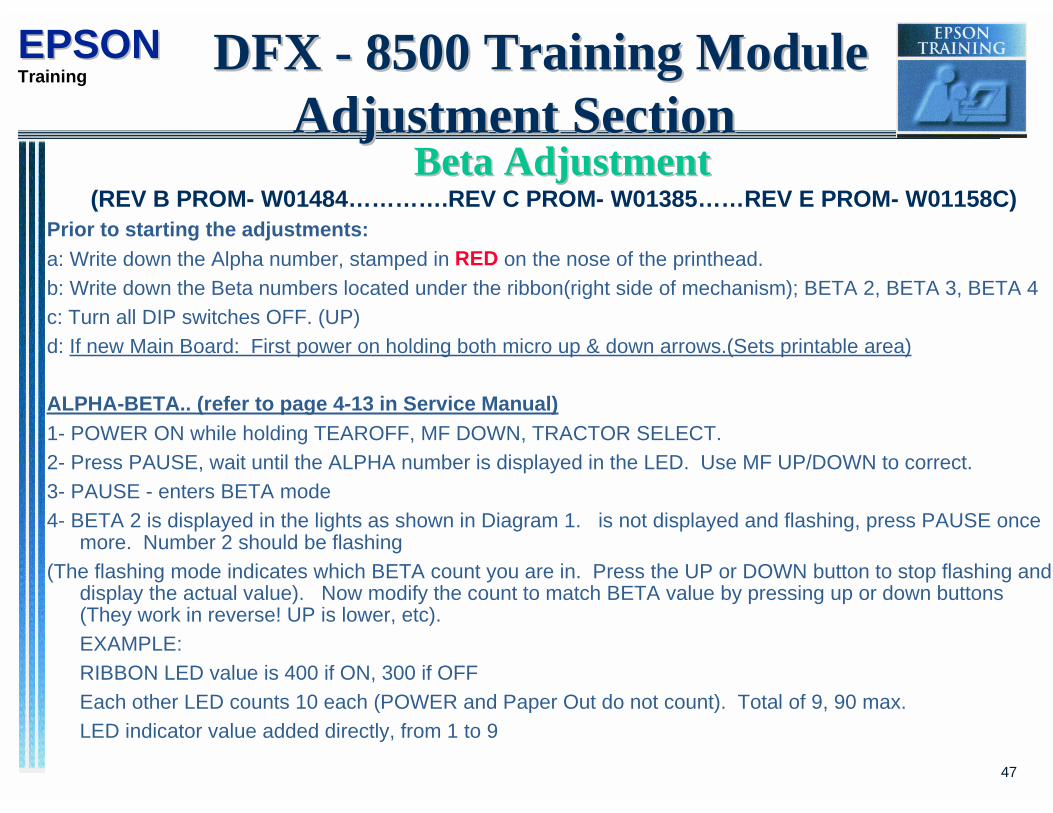
Beta AdjustmentBeta Adjustment(REV B PROM- W01484………….REV C PROM- W01385……REV E PROM- W01158C)
Prior to starting the adjustments:
a: Write down the Alpha number, stamped in RED on the nose of the printhead.
b: Write down the Beta numbers located under the ribbon(right side of mechanism); BETA 2, BETA 3, BETA 4
c: Turn all DIP switches OFF. (UP)
d: If new Main Board: First power on holding both micro up & down arrows.(Sets printable area)
ALPHA-BETA.. (refer to page 4-13 in Service Manual)
1- POWER ON while holding TEAROFF, MF DOWN, TRACTOR SELECT.
2- Press PAUSE, wait until the ALPHA number is displayed in the LED. Use MF UP/DOWN to correct.
3- PAUSE - enters BETA mode
4- BETA 2 is displayed in the lights as shown in Diagram 1. is not displayed and flashing, press PAUSE oncemore. Number 2 should be flashing
(The flashing mode indicates which BETA count you are in. Press the UP or DOWN button to stop flashing anddisplay the actual value). Now modify the count to match BETA value by pressing up or down buttons(They work in reverse! UP is lower, etc).
EXAMPLE:
RIBBON LED value is 400 if ON, 300 if OFF
Each other LED counts 10 each (POWER and Paper Out do not count). Total of 9, 90 max.
LED indicator value added directly, from 1 to 9
DFX - 8500 Training Module DFX - 8500 Training ModuleAdjustment SectionAdjustment Section

48
EPSONEPSONTraining
POW
PO
RIBBON
FONT PITCH COPY TOF PAUSE
TEAROFF
ON=400OFF=300 COUNT 10 EACH
LED- Adds 1-9
8
Diagram 1 Operator Panel
Beta AdjustmentBeta AdjustmentIf the RIBBON LED is ON, the value is 400. If nine of the other LEDs are ON the value is 90 (9 x 10).
If the LED shows 8, add 8. So the value would be as follows:
RIBBON ON = 400
Lights= 90
LED= 8
_______
Total 498
6- PAUSE to go to BETA 3. Repeat for BETA 3.
7- PAUSE to go to BETA 4. Repeat for BETA 4.
8- PAUSE, then POWER OFF to save.
9- THEN-- Power ON, let it initialize, then Power OFF. NOW it is ready for self-test.
DFX - 8500 Training Module DFX - 8500 Training ModuleAdjustment SectionAdjustment Section

49
EPSONEPSONTraining
BiBi-Directional Adjustment-Directional Adjustment
BI-DIRECTIONAL ADJUSTMENT.... (refer to Service Manual page 4-16)
1. Verify Switch 1-6 is OFF.
2. Power ON while holding TEAROFF, MF UP, TRACTOR SELECT.
3- LOAD paper (Recent PROM rev may LOAD and PRINT automatically).
4- Prints ALPHA, BETA, FLIGHT TIME.
5- Align printed rows using MF UP and DOWN. COPY= reprint. PAUSE= go tonext step.
6- SDR alignment, same way, PAUSE to go to next step.
7- DRF alignment, same way, PAUSE to go to next step.
8- NLQ.... repeat, then PAUSE.
9- POWER OFF to save settings.
DFX - 8500 Training Module DFX - 8500 Training ModuleAdjustment SectionAdjustment Section

50
EPSONEPSONTraining
MeasurementMeasurement Seeking and Seeking and BiBi-directional Printing-directional PrintingAdjustmentAdjustment
The Purpose of this Adjustment is to correct the printermechanism parameters which control Bi-directional printing.
This Adjustment is required only on the DFX 8500, and must bedone EVERYTIME the Main Logic Board has been replaced.
Failure to do this adjustment will cause the printer to go into anError condition and not print properly.
DFX - 8500 Training Module DFX - 8500 Training ModuleAdjustment SectionAdjustment Section

51
EPSONEPSONTraining
After Replacing Main PCB on DFX 8500, followAfter Replacing Main PCB on DFX 8500, followthis Procedure!!!this Procedure!!!
1) Measurement SeekingAdjustment
2) Printhead Flight timeAdjustment Value
3) Bi-directional PrintingAdjustment Value for each
Speed Mode.Super draft, Draft and NLQ
The Parametersto be written to the EEPROM
on the C204 Main Board ( DFX 8500)in these Adjustments should be done in this Order.
DFX - 8500 Training Module DFX - 8500 Training ModuleAdjustment SectionAdjustment Section
52
EPSONEPSONTraining
DFX - 8500 Training Module DFX - 8500 Training ModuleAdjustment SectionAdjustment Section
Measurement Seeking AdjustmentMeasurement Seeking Adjustment
Step 1: Turn the Power Switch on while pressing the Micro Feed Up& Micro Feed Down buttons at the same time.
Step 2: The Printer performs the Carriage measurement seekingautomatically. You will see the Carriage go back & forth, fast thenslow before finishing and returning to the an ON LINE Status. TurnPower Off.
53
EPSONEPSONTraining
DFX - 8500 Training Module DFX - 8500 Training ModuleAppendix / ReferenceAppendix / Reference
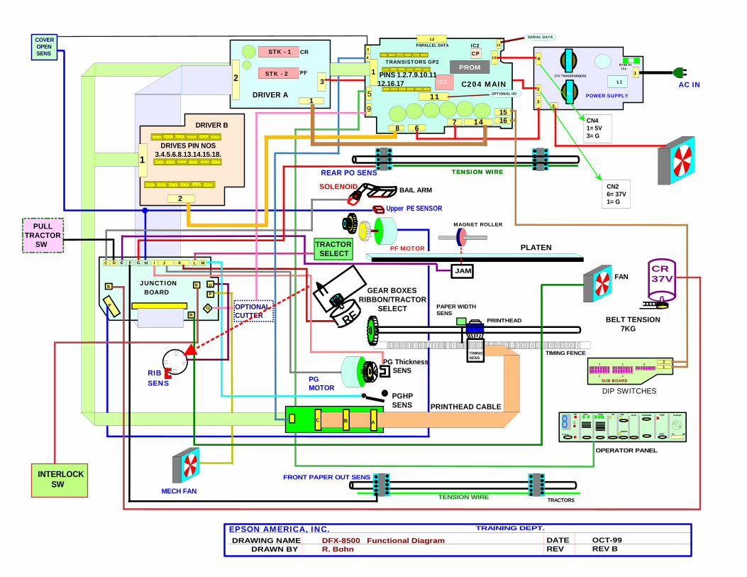
The Appendix / Reference sections containsThe Appendix / Reference sections containspages extracted from the service manual thatpages extracted from the service manual thatwill assist you in the repair of the DFX-8500. will assist you in the repair of the DFX-8500. It also contains functional diagrams, It also contains functional diagrams, part numbers, board and cable layoutspart numbers, board and cable layouts
JAM CR37V
TIMINGSENS
PGHPSENS
PG ThicknessSENS
BELT TENSION 7KG
PAPER WIDTHSENS
TIMING FENCE
RF
TRACTOR SELECT
REAR PO SENS
Upper PE SENSOR
BAIL ARMSOLENOID
TENSION WIRE
TTEENNSSIIOONN WWIIRREE
PRINTHEAD CABLE
TRACTORS
GEAR BOXESRIBBON/TRACTOR SELECT
PLATEN
PRINTHEAD
EPSON AMERICA, INC. TRAINING DEPT.
DATEREV
OCT-99REV B
DFX-8500 Functional DiagramR. Bohn
DRAWING NAME DRAWN BY
FUSE F1 15a
4
2
1
35
L137V TRANSFORMERS
POWER SUPPLY
STK - 1
STK - 23
1
2
CR
PF
PAPER SEL
8PP OOWW
PAPOUT
RIBBON
FF OONN TT PP II TTCC HH CC OOPP YY TTOOFF
TT EEAA RR OO FF FF
LLFF// FFFF MM II CCRROOFF EE EEDD PPAAUUSSEE
RREESS EE TT
TT RR SS EE LL EE CCTT
FFTT RRRR
C
OPERATOR PANEL
DRIVER A T1
T2
B A
D E F G H I
B O
A
JUNCTION BOARD
J K L M
P
N
Q
C
R
PROM
CP
IC1
8 67 14
1516
10
13
C204 MAIN
9
5
4
3
12
TRANSISTORS GP2
PINS 1.2.7.9.10.1112.16.17
1
2
DRIVER B
DRIVES PIN NOS 3.4.5.6.8.13.14.15.18.
COVER OPEN SENS
OPTIONALCUTTER
IC2
PULLTRACTOR SW PF MOTOR
MAGNET ROLLER
INTERLOCK SW
RIBSENS
MECH FAN
AC IN
PGMOTOR
11 OPTIONAL I/O
FAN
CN26= 37V1= G
CN41= 5V3= G
SERIAL DATA
PARALLEL DATA
1
1 3 5
2 4
21
SUB BOARD
DIP SWITCHES
FRONT PAPER OUT SENS

BAIL ARM SOLENOIDPULL TRACTOR SENSOR
JAM SENSORFRONT PAPER OUT
REAR PAPER OUT
UPPER PAPER ENDPLATEN GAP THICKNESS SENSORPLATEN GAP MOTOR
RIBBON FEED MOTORTRACTOR SELECT SWITCHPLATEN GAP HOME SWITCH
INTERLOCK SWITCH
RIBBON MOTION SENSORMECHANISM FAN
OPTIONAL CUTTER
CARRIAGE MOTOR FAN
DRIVER BOARD
PAPER FEED MOTOR
CARRIAGE MOTOR
PIN 1 POSITION MARKED AT EACH CONNECTOR
DFX-8500 JUNCTION BOARD
1 1 1 1 1 1 1 1 1 1 1
1 1
1
1
11
1

DFX-8500 PART NUMBERS
BOARDSMAIN 2023797 CAN BE EXCHANGED, PREFIX "E"POW SUPPLY, 117VAC 2023799 CAN BE EXCHANGED, PREFIX "E"DRIVER, MOT 2023803DRIVER B, PH 2023805JUNCTION 2023747
MOTORSCAR MOTOR 1039685PF MOTOR 2007992PLAT GAP MOTOR 2025899RIB MOTOR 2024065
TRACTORSFRONT- LEFT 1033544FRONT- RIGHT 1033112REAR- LEFT 1033545REAR - RIGHT 1033117TRACTOR STRING 1016058
MISCINTERLOCK SW, WIDE 2017404PRINTHEAD KIT 1043489PROM 2028532P.S. FAN 2025875SOLENOID, BAIL ARM 2011619
SENSORSJAM SENSOR 1040078PAPER WIDTH SENSOR 2023753PLAT GAP SENSOR F346151000TIMING SENSOR 2011561UPPER PE SENS 2000811

PRODUCT DESCRIPTION
1.4 OPERATING INSTRUCTIONSThis section describes the functions performed through the control panel, such as test printing, hexadecimaldumps, and paper memory functions.
CONTROL PANELThe printer control panel gives you easy control over most common printer operations. The panel consists ofthe indicator lights and buttons shown in Figure 1-22.
Paper Select
Power
PaperOut
Ribbon
Font Pitch CopyTop ofForm
Tear Off
LF/FFLoad
Pause
Reset
3sec
Tractor Select
PAPER SELECT
Front / Rear
Sper Draft
DfaftRoman
Sans serif
10 cpi
12 cpi15 cpi17 cpi
20 cpi
PS
MicroFeed
LED Off LED On
Figure 1-22. Control Panel

DFX-8500
ButtonsThe control panel contains eleven buttons.
Button Functions during No rmal Operat ion:During normal operation, control panel buttons perform the following functions. (See Table 1-15.)
Table 1-15. Button Functions during No rmal Operation
Button FunctionFront/Rear Toggles between the front and rear paper paths.Pause Toggles between printing and paused status.
Holding this button down for three seconds resets the printer.Micro Feed ↑ Feeds paper forward 1/216 inch.Micro Feed ↓ Feeds paper backward 1/216 inch.LF/FF Load Loads the paper when the printer is empty.
Pressing this button feeds paper forward one line. Holding this button down for a few seconds feeds paper forward one
page.TOF (top of form) Allows top of form position adjustment.
Allows loading position adjustment when pressed just after loadingpaper.
Tear Off Advances continuous paper to the tear-off position.Copy Toggles between multi-form copy and normal printing.Pitch Selects pitch.Font Selects font.Paper Select Selects memorized paper setting.
Operat ion with the Power Button:Control panel buttons perform the functions shown in Table 1-16 when pressed at the same time as thePower button.
Table 1-16. Button Function when Combined with the Power Button
Button FunctionLF/FF Load Draft self testTear Off NLQ self testTear Off and LF/FF Hex dumpPause DIP switch setting printoutLF/FF Load, Micro Feed ↓ and Pause* Clear EEPROM area 2Pause and Front/Rear† Clear EEPROM area 1Copy Clear ribbon counterPaper Select This button is used for paper memory storage and
recall. See “Paper Memory Functions” on page 1-38.
Tear Off, Micro Feed ↑, and Front/Rear Flight time adjustment (See Chapter 4.)Tear Off, Micro Feed ↓, and Front/Rear Platen gap adjustment (See Chapter 4.)Micro Feed ↑ and Micro Feed ↓ Sets printable area.
Note: For details, see “Advanced Control Panel Functions” on page 1-36.* All mechanism adjustment values are cleared. The printer mechanism adjustment must be performed after
this. (See Chapter 4.)† All user setting values are replaced with the factory setting values.
DFX-8500
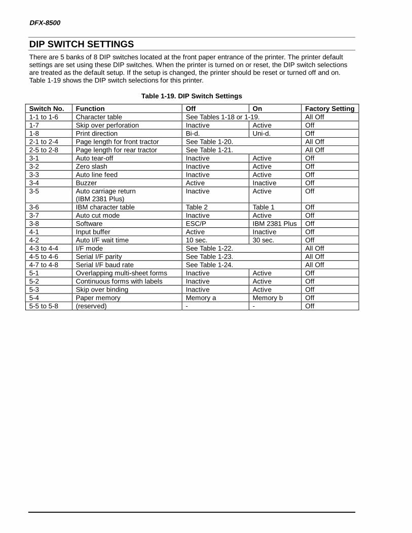
DIP SWITCH SETTINGSThere are 5 banks of 8 DIP switches located at the front paper entrance of the printer. The printer defaultsettings are set using these DIP switches. When the printer is turned on or reset, the DIP switch selectionsare treated as the default setup. If the setup is changed, the printer should be reset or turned off and on.Table 1-19 shows the DIP switch selections for this printer.
Table 1-19. DIP Switch Settings
Switch No. Function Off On Factory Setting1-1 to 1-6 Character table See Tables 1-18 or 1-19. All Off1-7 Skip over perforation Inactive Active Off1-8 Print direction Bi-d. Uni-d. Off2-1 to 2-4 Page length for front tractor See Table 1-20. All Off2-5 to 2-8 Page length for rear tractor See Table 1-21. All Off3-1 Auto tear-off Inactive Active Off3-2 Zero slash Inactive Active Off3-3 Auto line feed Inactive Active Off3-4 Buzzer Active Inactive Off3-5 Auto carriage return
(IBM 2381 Plus)Inactive Active Off
3-6 IBM character table Table 2 Table 1 Off3-7 Auto cut mode Inactive Active Off3-8 Software ESC/P IBM 2381 Plus Off4-1 Input buffer Active Inactive Off4-2 Auto I/F wait time 10 sec. 30 sec. Off4-3 to 4-4 I/F mode See Table 1-22. All Off4-5 to 4-6 Serial I/F parity See Table 1-23. All Off4-7 to 4-8 Serial I/F baud rate See Table 1-24. All Off5-1 Overlapping multi-sheet forms Inactive Active Off5-2 Continuous forms with labels Inactive Active Off5-3 Skip over binding Inactive Active Off5-4 Paper memory Memory a Memory b Off5-5 to 5-8 (reserved) - - Off

PRODUCT DESCRIPTION
Table 1-20. Character Table Sett ing (Standard)
SW1-1 SW1-2 SW1-3 SW1-4 SW1-5 SW1-6 Character tableOff Off Off Off Off Off PC437 (US, standard Europe)Off Off Off Off Off On PC850 (Multilingual)Off Off Off Off On Off PC860 (Portuguese)Off Off Off Off On On PC861 (Icelandic)Off Off Off On Off Off PC863 (Canadian-French)Off Off Off On Off On PC865 (Nordic)Off Off Off On On Off AbicompOff Off Off On On On BRASCIIOff Off On Off Off Off Roman 8Off Off On Off Off On ISO Latin 1Off Off On Off On Off Italic USAOff Off On Off On On Italic FranceOff Off On On Off Off Italic GermanOff Off On On Off On Italic U.KOff Off On On On Off Italic DenmarkOff Off On On On On Italic SwedenOff On Off Off Off Off Italic ItalyOff On Off Off Off On Italic Spain
Others PC437

DFX-8500
Table 1-21. Character Table Sett ing (NLSP)
SW1-1 SW1-2 SW1-3 SW1-4 SW1-5 SW1-6 Character tableOff Off Off Off Off Off PC437 (US, standard Europe)Off Off Off Off Off On PC850 (Multilingual)Off Off Off Off On Off PC437 GreekOff Off Off Off On On PC852 East EuropeOff Off Off On Off Off PC853Off Off Off On Off On PC855 (Cyrillic)Off Off Off On On Off PC857 (Turkish)Off Off Off On On On PC866 (Russian)Off Off On Off Off Off PC869 (Greek)Off Off On Off Off On MAZOWIA (Poland)Off Off On Off On Off Code MJK (CSFR)Off Off On Off On On ISO 8859-7 (Latin/Greek)Off Off On On Off Off ISO Latin 1T (Turkish)Off Off On On Off On Bulgaria (Bulgarian)Off Off On On On Off Estonia (Estonia)Off Off On On On On PC774 (LST 1283:1993)Off On Off Off Off Off ISO8859-2Off On Off Off Off On PC866LAT (Latvian)Off On Off Off On Off PC866 UKROff On Off Off On On PCAPTECOff On Off On Off Off PC708Off On Off On Off On PC720Off On Off On On Off PC AR864Off On Off On On On PC860(Portuguese)Off On On Off Off Off PC861(Icelandic)Off On On Off Off On PC865(Nordic)Off On On Off On Off Italic USAOff On On Off On On Italic FranceOff On On On Off Off Italic GermanOff On On On Off On Italic U.KOff On On On On Off Italic DenmarkOff On On On On On Italic SwedenOn Off Off Off Off Off Italic ItalyOn Off Off Off Off On Italic Spain
Others PC437

PRODUCT DESCRIPTION
Table 1-22. Front Tractor Page Length
SW2-1 SW2-2 SW2-3 SW2-4 Page length for front tractorOff Off Off Off 11 inchesOff Off Off On 3 inchesOff Off On Off 3.5 inchesOff Off On On 4 inchesOff On Off Off 5.5 inchesOff On Off On 6 inchesOff On On Off 7 inchesOff On On On 8 inchesOn Off Off Off 8.5 inchesOn Off Off On 70/6 inchesOn Off On Off 12 inchesOn Off On On 14 inchesOn On Off Off 17 inchesOn On Off On Others
Others 11 inches
Table 1-23. Rear Tractor Page Length
SW2-1 SW2-2 SW2-3 SW2-4 Page length for rear tractorOff Off Off Off 11 inchesOff Off Off On 3 inchesOff Off On Off 3.5 inchesOff Off On On 4 inchesOff On Off Off 5.5 inchesOff On Off On 6 inchesOff On On Off 7 inchesOff On On On 8 inchesOn Off Off Off 8.5 inchesOn Off Off On 70/6 inchesOn Off On Off 12 inchesOn Off On On 14 inchesOn On Off Off 17 inchesOn On Off On Others
Others 11 inches
Table 1-24. I/F Selection
SW4-3 SW4-4 I/F ModeOff Off AutoOff On Parallel I/FOn Off Serial I/FOn On Optional I/F
Table 1-25. Serial I/F Parity Setting
SW4-5 SW4-6 Serial parityOff Off NoneOff On OddOn Off EvenOn On Ignore

DFX-8500
Table 1-26. Serial I/F Baud Rate Setting
SW4-7 SW4-8 Baud rateOff Off 19200Off On 9600On Off 4800On On 2400
CONTROL PANEL FUNCTIONS
Normal Operation Front / Rear:Toggles between the front and rear paper paths.
If the printer is set to use normal paper and the pull t ractor is not used:The printer feeds the paper to the tear off position, cuts the paper using the cutter, and feeds the paperbackward to the paper park position. A paper change incomplete error occurs if the cutter is not used. Ifyou aren’t using the cutter, cut the paper above the platen, then press the Pause or Front/Rear button.The printer feeds the paper backward. After the paper is out, the printer loads paper from the other path’stractor.
If the printer is set to use overla pping multi-sheet fo rms or cont inuous fo rms with labels (DIPswitches 5-1 or 5-2 are on) or the pull t ractor is used:
A paper change incomplete error occurs immediately. Cut the paper below the platen, then press thePause or Front/Rear button. The printer feeds the paper forward. After the paper is out, the printer loadspaper from the other path’s tractor.
Pause:This button causes the printer to pause.Hold this button down for 3 seconds to reset all printer data.Press this button to clear a paper change incomplete error.
Micro feed:Adjusts the paper position, the top of form position, and the tear off position. The ↑ button advances thepaper 1/216 inch, and the ↓ button retracts the paper 1/216 inch.
LF/FF Load:Pressing this button advances the paper one line.Holding this button down for a few seconds advances the paper one page.When the printer is out of paper, pressing this button will load continuous paper.
Top of Form:Pressing this button starts the top of form adjustment mode, turns on the top of form LED, and advances thepaper until the character base line lies directly beneath the red mark on the ribbon mask holder. You canadjust the top of form position using the Micro Feed buttons while in this mode. Press the Top of Formbutton again to exit the top of form adjustment mode. The adjusted position is stored as the new top of formposition, and the paper is retracted to its normal printing position.If you adjust the top of form position just after loading, the adjusted position will be treated as the loadingposition. This button is inactive if the printer cover is closed.
Tear Off:Pressing this button starts the tear off adjustment mode, turns on the tear off LED, and advances the paperuntil the perforation lies directly beneath the cutting edge of the printer cover. You can adjust the tear offposition using the Micro Feed buttons while in this mode. Press the Tear Off button again to cut the paper(optional cutter required) and exit the tear off adjustment mode. The adjusted position is stored as the newtear off position, and the paper is retracted to its normal printing position. The printer will also exit this mode

PRODUCT DESCRIPTION
if it receives data from the host computer.
Copy:This button toggles the printer between copy mode or normal mode.
Pitch:Press this button to select among the following pitches:
10 cpi, 12 cpi, 15 cpi, 17 cpi, 20 cpi and PS (proportional spacing)
Font:Press this button to select among the following fonts:
Super Draft, Draft, Roman, Sans Serif
Paper Select:Paper sizes can be preset. Pressing this button selects one of the following preset paper sizes:
1, 2, 3, 4, 5, 6, 7, and 8: Paper sizes must be created within the printer driver. See the User’s Guide for details.
0: Default; use when no driver settings have been made.a, b: Hardware settings used for sheets with labels. See the User’s Guide for
details.
If the printer is set to use normal paper and the pull t ractor is not used:Pressing this button retracts the paper to the paper park position. If a print job was just performed, theprinter will advance the paper to the tear off position and cut the paper (if the optional cutter is installed).If the cutter is not installed, a paper change incomplete error occurs. Manually cut the paper above theplaten, then press the Pause button. The printer will retract the paper. After the new paper has beenplaced into position, the printer will load the new paper. If a paper change incomplete error occurred,insert the new paper and press the Pause button to load it.
If the printer is set to use overla pping multi-sheet fo rms or cont inuous fo rms with labels (DIPswitches 5-1 or 5-2 are on) or the pull t ractor is used:
Pressing this button will cause an immediate paper change incomplete error. Manually cut the paperbelow the platen, then push the Pause button. The printer will advance the paper until it is out, then loadthe selected paper. If you get another paper change incomplete error, insert the new paper and press thePause button to load it.
If the paper setting is cu rrently sett ing a or b:The printer advances the paper. If a paper path change incomplete error occurs, cut the paper belowthe platen and press the Pause button. The printer ejects the paper.
If the printer is not currently us ing the a and b settings:The printer advances the paper to the tear-off position and cuts the paper if the cutter is installed.The printer then retracts the paper to the paper park position. If the cutter is not installed, or theprinter fails to advance the paper to the paper park position, a paper path change incomplete errorwill occur. If this happens, cut the paper above the platen, then press the Pause button. The printerretracts the paper.
DFX-8500
Advanced Control Panel Functions
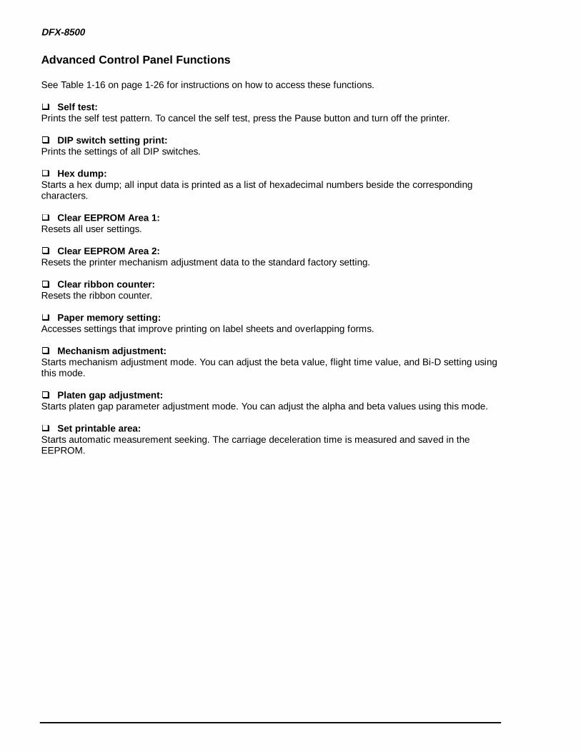
See Table 1-16 on page 1-26 for instructions on how to access these functions.
Self test:Prints the self test pattern. To cancel the self test, press the Pause button and turn off the printer.
DIP switch setting print:Prints the settings of all DIP switches.
Hex dump:Starts a hex dump; all input data is printed as a list of hexadecimal numbers beside the correspondingcharacters.
Clear EEPROM Area 1:Resets all user settings.
Clear EEPROM Area 2:Resets the printer mechanism adjustment data to the standard factory setting.
Clear r ibbon counter:Resets the ribbon counter.
Paper memory sett ing:Accesses settings that improve printing on label sheets and overlapping forms.
Mechanism adjustment:Starts mechanism adjustment mode. You can adjust the beta value, flight time value, and Bi-D setting usingthis mode.
Platen gap adjustment:Starts platen gap parameter adjustment mode. You can adjust the alpha and beta values using this mode.
Set printable area:Starts automatic measurement seeking. The carriage deceleration time is measured and saved in theEEPROM.

TROUBLESHOOTING
5.1 TROUBLESHOOTING INFORMATIONThis chapter lists various problems that can occur with the DFX-8500 and provides possible solutions. Nospecial tools, other than a digital multi-meter, are necessary to troubleshoot at the unit level. Somecomponent-level troubleshooting may require an oscilloscope.
ERROR MESSAGESThe DFX-8500 indicates errors using beeps. Tables 5-1 and 5-2 list standard errors.
Table 5-1. Error/Warning Beeper Information
Error/Warning PauseLED
Paper OutLED
RibbonLED
Beeper Description
Printhead hot Blinking Off Off —Printhead fan hot Blinking Off Off —Paper out On On Off . . . This error occurs when the
printer fails to load a sheet.(Three 100-ms beeps with a100-ms interval.)
Cover open ON Off Off . . . This error occurs when theprinter’s cover is open.
Paper changeincomplete
On Off Off . . . This error occurs when theprinter fails to change the paper.
Paper backfeedincomplete
On Blinking Off . . .
Paper size error ON Off Off . . . This error occurs when the setpaper width and the currentpaper size are different.
Paper jam ON Blinking Off - - - - - This error occurs when theprinter fails to eject a sheet.(Five 500-ms beeps with a100-ms interval.)
Ribbon jam On Off Blinking - - - - - This error occurs when theribbon jams or when no ribbon isinstalled.
Carriage motorerror
On Blinking Blinking - - - - - This error occurs when thecarriage deceleration time isabnormal.
Illegal paneloperation
— — — —

DFX-8500
Table 5-2. Fatal Error Information
Fatal Error 7-segmentLED *
Beeper † Description Note ‡
Carriage motorcircuit short
1 - The isolation resistance in the carriagemotor is too low.
Auto power offafter 12 seconds
Cutter error 2 - - • The optional cutter cable is notconnected securely.
• The optional cutter is defective.
Auto power offafter 12 seconds
Platen gaperror
3 - - - • The PG home sensor is broken.• The PG motor is broken.• The parallelism adjustment is
incorrect.• PG adjustment values are incorrect.• PG motor pinion is too tight against
the PG transmission gear.
Auto power offafter 12 seconds
Carriage lockerror
4 - - - - The carriage is locked. Auto power offafter 12 seconds
Encoder error 4 - - - - The encoder sensor is defective. Auto power offafter 12 seconds
Carriage loadmeasurementerror
6 - - - - - - PW sensor is defective. Auto power offafter 12 seconds
Head fan error 7 - - - - - - - • The head fan driver IC is shorted.• The head fan is defective.
Printhead poweroff immediately
Printheadcircuit short
8 - - - - - - - - • The printhead driver IC is shorted.• The printhead coil is defective.
Printhead poweroff immediately
RAM checkerror
9 - - - - - - - - - The DRAM on the main board isdefective.
Auto power offafter 12 seconds
Paper memorysetting error
a - - - - - - - - - - - -
EEPROM datacompare error
b - - - - - - - - - - - The EEPROM is defective.
Tractor changeerror
c - - - - - - - - - - - - The tractor select mechanism or ribbonfeed motor is defective.
Auto power offafter 12 seconds
Internal CPUerror
d The main board is defective. Auto power offafter 12 seconds
*: During a fatal error, the 7 segment LED alternately flashes an “E” and the error number.†: 500 ms beeps with 100 ms intervals.‡: Turn the printer power off while the 7 segment LED is on, or the printer will shut down. The printer will not
turn back on for 5 minutes after the printer shuts down automatically.

TROUBLESHOOTING
BYPASSING THE INTERLOCK SWITCH AND COVER OPEN SENSORTo print with the top cover open or removed, you need to bypass the interlock switch and cover open sensor.These sensors automatically disable printing when the top cover is open.
Cover Open Sensor
Interlock Switch
CN3
ConnectorJunction Board
C204 Main Board
Figure 5-1. Interlock Switch and Co ver Open Sensor
The interlock switch and cover open sensor are attached. To bypass the interlock switch and the cover opensensor, follow these steps:
1. Remove the left side cover.2. Remove the interlock switch and cover open sensor from the housing.3. Insert a half-inch spacer (for example, an eraser) as shown in Figure 5-2.
0.51 inch(13 mm)
Spacer
Interlock Switch
Cover Open Sensor
To CN3 on the Main Board
To Connector Junction Board
Figure 5-2. Bypassing the Interlock Switch and Co ver Open Sensor
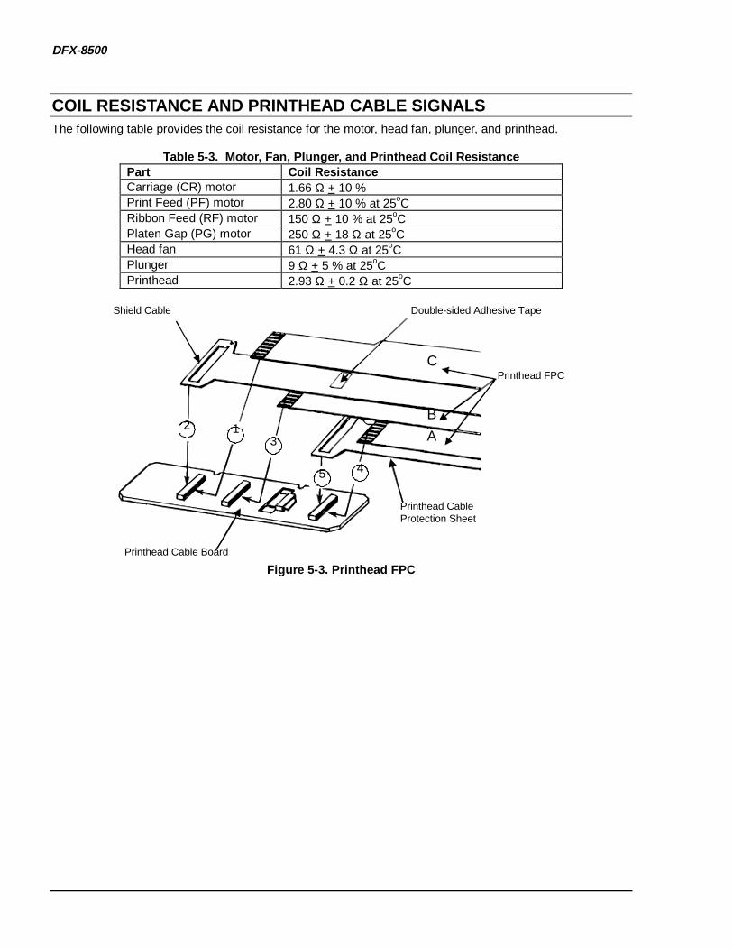
DFX-8500
COIL RESISTANCE AND PRINTHEAD CABLE SIGNALSThe following table provides the coil resistance for the motor, head fan, plunger, and printhead.
Table 5-3. Motor, Fan, Plunger, and Printhead Coil ResistancePart Coil ResistanceCarriage (CR) motor 1.66 Ω + 10 %Print Feed (PF) motor 2.80 Ω + 10 % at 25oCRibbon Feed (RF) motor 150 Ω + 10 % at 25oCPlaten Gap (PG) motor 250 Ω + 18 Ω at 25oCHead fan 61 Ω + 4.3 Ω at 25oCPlunger 9 Ω + 5 % at 25oCPrinthead 2.93 Ω + 0.2 Ω at 25oC
Printhead Cable Board
Printhead Cable Protection Sheet
Printhead FPC
Double-sided Adhesive TapeShield Cable
123
45
C
B
A
Figure 5-3. Printhead FPC
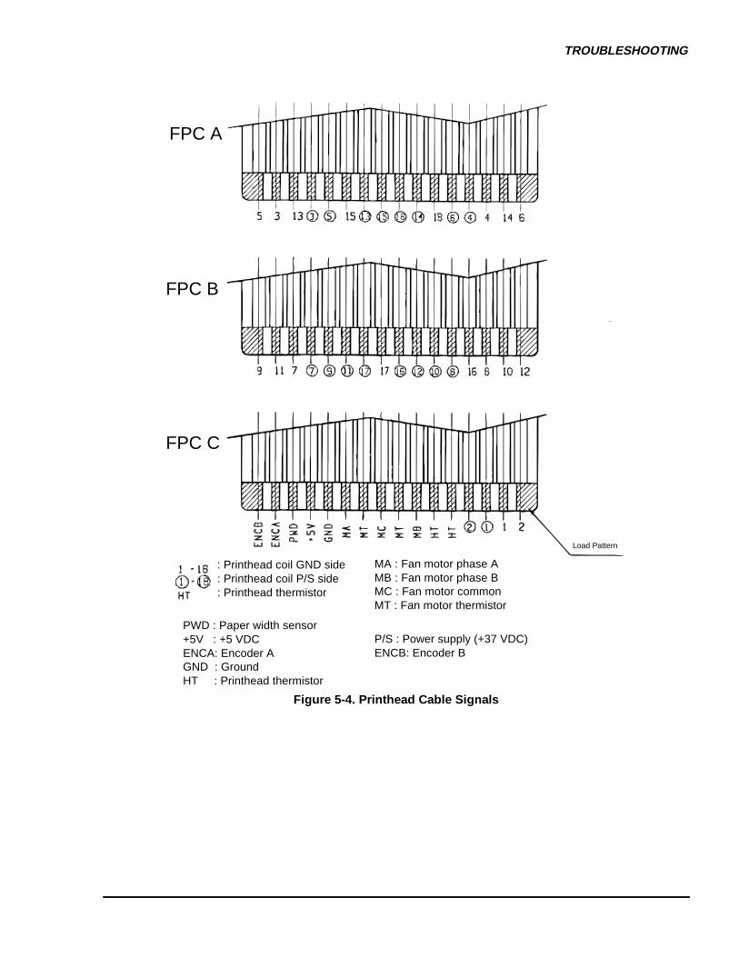
TROUBLESHOOTING
FPC A
FPC B
FPC C
Load Pattern
: Printhead coil GND side: Printhead coil P/S side: Printhead thermistor
MA : Fan motor phase AMB : Fan motor phase BMC : Fan motor commonMT : Fan motor thermistor
PWD : Paper width sensor+5V : +5 VDCENCA: Encoder AGND : GroundHT : Printhead thermistor
P/S : Power supply (+37 VDC)ENCB: Encoder B
Figure 5-4. Printhead Cable Signals

CHAPTER 4ADJUSTMENT
4.1 PRINTER MECHANISM ADJUSTMENTS ............................................................4-1 4.1.1 PG Motor Backlash Adjustment........................................................................................... 4 -1
4.1.2 Carriage Timing Belt Tension Adjustment .......................................................................... 4-2
4.1.3 Tractor Wire Spring Tension Adjustment........................................................................... 4-3
4.1.4 Pull Tractor Sensor Position Adjustment............................................................................ 4-4
4.1.5 Carriage Guide Shaft Parallelism Adjustment .................................................................... 4-5
4.1.6 Platen Angle Adjustment ................................................................................................. ..... 4-9
4.1.7 Platen Gap Motor Value Adjustment.................................................................................. 4-12
4.1.8 Measurement Seeking and Bi-directional Printing Adjustment...................................... 4-15

ADJUSTMENT
Rev. B 4-1
4.1 PRINTER MECHANISM ADJUSTMENTSThis section describes the printer mechanism adjustments for the DFX-8500. Whenever the printer isdisassembled and the printer parts mentioned in this section are replaced or repaired, perform theappropriate adjustments to ensure proper printer operation. Perform adjustments before assembling theprinter.
4.1.1 PG Motor Backlash AdjustmentIn the PG motor backlash adjustment, the PG motor pinion gear must mesh smoothly with the PGtransmission gear cog. If the pinion gear is poorly aligned or the pinion gear and cog are too tight, printeroperation is noisy or the character density is incorrect.
;If the PG motor backlash is too tight, PG motor doesn’t rotate smoothly and the panel indicates “E3.”
Step 1: Loosen the two screws securing the PG motor to the left side frame. (Refer to Section 3.2.6.4)Step 2: Make sure the PG motor pinion gear is properly aligned with the PG transmission gear cog. Move
the PG motor until there is 0.05 to 0.15 mm (0.002 to 0.01 inches) between the PG motor pinion gearand PG transmission gear cog. Then tighten the two screws.
CAUTION
P G T r a n s m i s s i o n G e a r
0 . 0 5 - 0 . 1 5 m m
P G M o t o rP i n i o n G e a r
S c r e w s P G M o t o r
Figure 4-1. PG Motor Mounting Position Adjustment
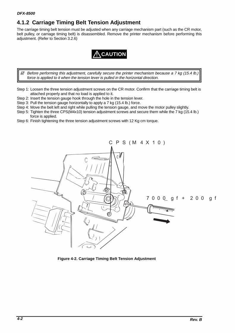
DFX-8500
Rev. B4-2
4.1.2 Carriage Timing Belt Tension AdjustmentThe carriage timing belt tension must be adjusted when any carriage mechanism part (such as the CR motor,belt pulley, or carriage timing belt) is disassembled. Remove the printer mechanism before performing thisadjustment. (Refer to Section 3.2.6)
;Before performing this adjustment, carefully secure the printer mechanism because a 7 kg (15.4 lb.)force is applied to it when the tension lever is pulled in the horizontal direction.
Step 1: Loosen the three tension adjustment screws on the CR motor. Confirm that the carriage timing belt isattached properly and that no load is applied to it.
Step 2: Insert the tension gauge hook through the hole in the tension lever.Step 3: Pull the tension gauge horizontally to apply a 7 kg (15.4 lb.) force.Step 4: Move the belt left and right while pulling the tension gauge, and move the motor pulley slightly.Step 5: Tighten the three CPS(M4x10) tension adjustment screws and secure them while the 7 kg (15.4 lb.)
force is applied.Step 6: Finish tightening the three tension adjustment screws with 12 Kg cm torque.
CAUTION
7 0 0 0 g f + 2 0 0 g f
C P S ( M 4 X 1 0 )
Figure 4-2. Carriage Timing Belt Tension Adjustment

ADJUSTMENT
Rev. B 4-3
4.1.3 Tractor Wire Spring Tension AdjustmentThis section describes the tractor wire spring tension adjustment. If the spring is not adjusted properly, paperjams may occur, because the continuous paper tension (in the horizontal direction) is incorrect. When youremove the front or rear tractor assembly, perform this adjustment.
Step 1: Remove the printer mechanism. (Refer to Section 3.2.6)Step 2: Release the release levers for the tractor sprockets on the front.Step 3: At the left side frame, loosen the CBS(M4 X 8) screws securing the wire holding plate (L).Step 4: Pull the tractor wire left to make correct tension to the tractor wire, wire holding plate ( R) and the tip
of the gold seal are 5 mm (0.2 inches) apart.Step 5: Fix the CBS(M4 X 8) screws on the wire holding plate (L).Step 6: As the same manner, adjust the tractor spring tension for the rear tractor.
T r a c t o r W i r eT e n s i o n S p r i n g
T e n s i o n S p r i n g
G o l d S e a l
5 m m
T r a c t o r W i r e
W i r e H o l d i n g P l a t e ( R )
1 0 - 1 5 m m
W i r e H o l d i n g P l a t e ( L )
T r a c t o r W i r e
C B S ( M 4 X 8 )
T r a c t o r R e l e a s e L e v e r
P u l l , a d j u s t , f i x , a n d c u t h e r e .
Figure 4-3. Tractor Wire Tension Adjustment (Front)
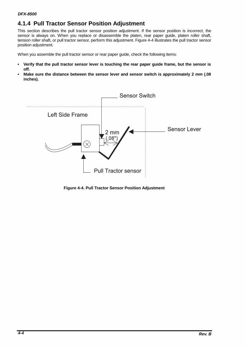
DFX-8500
Rev. B4-4
4.1.4 Pull Tractor Sensor Position AdjustmentThis section describes the pull tractor sensor position adjustment. If the sensor position is incorrect, thesensor is always on. When you replace or disassemble the platen, rear paper guide, platen roller shaft,tension roller shaft, or pull tractor sensor, perform this adjustment. Figure 4-4 illustrates the pull tractor sensorposition adjustment.
When you assemble the pull tractor sensor or rear paper guide, check the following items:
• Verify that the pull tractor sensor lever is touching the rear paper guide frame, but the sensor isoff.
• Make sure the distance between the sensor lever and sensor switch is approximately 2 mm (.08inches).
( . 0 8 " )
L e f t S i d e F r a m e
S e n s o r S w i t c h
S e n s o r L e v e r
P u l l T r a c t o r s e n s o r
2 m m
Figure 4-4. Pull Tractor Sensor Position Adjustment

ADJUSTMENT
Rev. B 4-5
4.1.5 Carriage Guide Shaft Parallelism AdjustmentThe rear carriage guide shaft must be parallel to the platen. If it is not, printing may be abnormal becausepaper is not fed evenly at the left and right sides of the platen. A paper jam may occur. This adjustment isrequired when the rear carriage guide shaft is removed during carriage mechanism disassembly, theparallelism adjust lever is moved, or the platen is removed. Do not remove the printer mechanism (If removethe printer mechanism from the lower case, the adjust value will be out of order when you reassemble theprinter mechanism to the lower case.) Also, it is necessary to remove the tension roller shaft beforeperforming this adjustment. (Refer to Section 3.2.6.7.)
The parallelism is adjusted so that the difference between the distances (from the rear carriage guideshaft to the platen measured at the two positions shown in Figure 4-5) is less than + 0.015 mm. Sincethis value is extremely small, you must use the two dial gauges, dial gauge base, and dial gaugemaster supplied by EPSON. Do not adjust the parallelism using any other method.
; Dial gauges (x 2) #F610 (Part No. B1019466)
;Dial gauge base #F611 (Part No. B1019467)
;Dial gauge master #F612 (Part No. B1019468).
Before performing the carriage guide shaft parallelism adjustment, you must assemble the two dial gauges,dial gauge base, and dial gauge master to form one tool. Follow these steps:
Step 1: Attach the two thumb screws for the dial gauge base to the dial gauge master. To eliminate any playbetween the dial gauge base and the dial gauge master, pull the tie band to secure the dial gaugebase and the dial gauge master before you securing the thumb screws.(Do procedure with two men.)
Step 2: Attach a dial gauge needle to the surface of the dial gauge master (approx. 2.00 mm depth), thentighten the hexagonal screw securing the dial gauge to the dial gauge base.
CAUTION
Figure 4-5. Set Dial Gauge to Dial Gauge Base
1. Attach the gauge needle to the master surface.
2. Tighten the hexagonal screw.
Figure 4-6. Dial Gauge Set Up 1

DFX-8500
Rev. B4-6
Step 3: Attach the another needle to the master surface, APPROX. 2.00 mm depth, then correspond to theanother gauge measure, and tighten the hexagonal screw.
Step 5: Set the black marker to the "0" position.
2. Attach the gauge needle to the master surface, then correspond to the another gauge measure.
3. Tighten the hexagonal screw.
Figure 4-7. Dial Gauge set Up 2
Figure 4-8. Black Marker to “0” Position Setting

ADJUSTMENT
Rev. B 4-7
Step 6: Remove a CP(PS)(M3X6) screw securing the timing belt holder to the timing belt, then remove thetiming belt holder.
Step 7: Remove the paper bail assembly. (Refer to Section 3.2.6.5.)Step 8: Remove the tension roller shaft. (Refer to Section 3.2.6.7.)Step 9: Remove the printhead with the mask-less holder. (Refer to Section 3.2.1.)Step 10: Attach the dial gauge base with the dial gauge in the same way as you attach the print head.
Then you attach this tool to the carriage, tighten the two thumb screws while you pulling the dialgage base toward you.
Step 11: Using the carriage guide shaft gear, adjust the gauge mounting position so that the tips of thegauges (portions A and B in the Figure 4-10) are securely attached to the platen.
C P ( P S ) M 3 X 6 )
T i m i n g B e l t H o l d e r
C a r r i a g e
C a r r i a g e G u i d e S h a f t ( R e a r )
Figure 4-9. Carriage Plate Removal
010
10 20
20
30
30010
10 20
20
30
30
P l a t e n
D i a l G a u g e B a s e
D i a l G a u g e M a s t e r
D i a l G a u g e x 2
T i e b a n d
A B
C a r r i a g e
Carria
ge G
uide Shaft (R
)
Carria
ge G
uide Shaft G
ear
R e f e r t o F i g u r e 4 - 1 0 a .
Figure 4-10. Dial Gauge Attachment
S t o p p e r
P G T r a n s m i s s i o n G e a r
C R G u i d e S h a f t G e a r
Figure 4-10a. CR Guide Shaft Gear Positioning

DFX-8500
Rev. B4-8
Step 12: Measure the distance between the platen and the carriage guide shaft on the left side. Thenmeasure the distance between the platen and the rear carriage guide shaft on the right side, andcompare these values.(Figure4-11 shows the measurement position and the parallelism adjustlever operation.)
Note: When you shift the carriage manually, do not touch the both dial gauges. Rotate the carriage motor pulley.
Step 13: If the distance measured at the left side is greater than that measured at the right side, move theparallelism adjust lever in the direction shown by the white arrow in Figure 4-9. If the distancemeasured at the left side is less than that measured at the right side, move the lever in thedirection shown by the black arrow.
Notes 1: The carriage guide shaft moves as shown in Figure 4-8. For example, when the parallelism adjust lever is moved in the direction of the black arrow, the distance betweenthe right side of the platen and printhead nose narrows a little bit.
Notes 2: The carriage guide shaft moves as shown in Figure 4-8. When the parallelism adjust leveris moved in the direction of the black arrow, the distance between the right side of theplaten and print head nose narrows a little bit.
Step 14: Repeat steps 11 and 12 until the distance between the distance measured at the two positions isless than + 0.015 mm.(The #F610 dial gauge matches the + "15" notches.)
Step 15: When the distance is within the specified range, tighten the two CP(PS)(M4 X 6) screws securingthe parallelism adjustment lever. Then measure the distances again, as described in step 11.
Step 16: If the distance between the measured distances is within the specified range, apply screw lock to the two screws.(Refer to Section 6.2 for lubrication and adhesive application instructions.)
Step 17: Go to Section 4.1.6 platen angle adjustment.
C a r r i a g e P a r a l l e l i s m
C a r r i a g e M o t o r
M o t o r P u l l e y
7 0 m m 7 0 m m
010
10 20
20
30
30
R i g h t S i d e F r a m e
A d j u s t L e v e r
Figure 4-11. Carriage Guide Shaft Parallelism Adjustment
Carriage Guide Shaft Rear
Parallelism Adjustment Lever
CP(PS)(M4X6)
Guide Shaft Holder Lever(Right)
Guide Shaft Holding Spring
CP(PS)(M4X6)
CBS(O)(M4X8)Carriage Motor Holder
Figure 4-12. Parallelism Adjustment Lever Operation

ADJUSTMENT
Rev. B 4-9
4.1.6 Platen Angle AdjustmentThis section describes the platen angle adjustment. The platen must be at a right angle to the carriageassembly. This adjustment is required when the platen is removed or replaced or when the two hexagonalscrews securing the platen to both side frames are loosened. Do not remove the printer mechanism from thelower case. (If remove the printer mechanism from the lower case, the adjust value will be out of order whenyou reassemble the printer mechanism to the lower case.) Also, it is necessary to remove the tension rollershaft be fore performing this adjustment. (Refer to Section 3.2.6.7)
The parallelism is adjusted so that the difference between the distances (from the rear carriage guideshaft to the platen measured at the two positions shown in Figure 4-7) is less than + 0.015 mm. Sincethis value is extremely small, you must use the two dial gauges, dial gauge base, and dial gaugemaster supplied by EPSON. Do not adjust the parallelism using any other method.
; Dial gauge #F610 (Part No. B1019466)
;Dial gauge base #F611 (Part No. B1019467)
;Dial gauge master #F612 (Part No. B1019468).
Step 1: Perform the carriage guide shaft parallelism adjustment. (Refer to section 4.1.5) After the adjustment is finished, leave the dial gage unit on the carriage.
Step 2: Remove the pull tractor sensor.(Refer to Section 3.2.6.10.)Step 3: Loosen (but do not remove) the two hexagonal screws securing the platen stay to both side frames.
CAUTION
H e x a g o n a l S c r e w s ( M 4 X 8 )
P l a t e n S t a y ( R )P l a t e n S t a y ( L )P o s i t i o n i n g T a b
P o s i t i o n i n g T a b
S i d e F r a m e R S i d eS i d e F r a m e L S i d e
Figure 4-13. Loosing Hexagonal Screws

DFX-8500
Rev. B4-10
Step 4: Using the carriage guide shaft gear, attach the both dial gauge needles to the platen surface.(Theneedle doesn’t reach the end of the stroke).
Step 5: Measure the angle difference about three position such as figure below.(Using the CR motorpulley to move the carriage with the dial gauge toward the right side. See Figure 4-11.)
C a r r i a g e g u i d e S h a f t G e a r
S i d e F r a m e ( L )
C a r r i a g e G u i d e S h a f t
P l a t e n
A t t a c h b o t h n e e d l e s .
R e f e r t o F i g u r e 4 - 1 0 a .
Figure 4-14. Attaching Two Needles to Platen Surface
010
10 20
20
30
30010
10 20
20
30
30
Platen
010
10 20
20
30
30010
10 20
20
30
30010
10 20
20
30
30010
10 20
20
30
30
Center Position70 mm 70 mm
Figure 4-15. Measuring Angle Difference 1

ADJUSTMENT
Rev. B 4-11
Step 6: If the angle difference of two values are more than + 0.015 mm, loosen (but do not remove) the twohexagonal screws securing the platen stay to both side frames, then change the platen angle slowllyand manually.)
Step 7: Tighten two hexagonal screws securing the platen stay to both side frames.
After perform the adjustment, confirm the value of platen parallelism again. When this value is out oforder, readjust the platen parallelism and the platen angle adjustment until the value to be correct.
P l a t e nB i t A
B i t B
( A n g l e A d j u s t m e n t M e t h o d )
U p
D o w n
Figure 4-16. Measuring Angle Difference 2
CAUTION

ADJUSTMENT
Rev. B 4-15
4.1.8 Measurement Seeking and Bi-directional Printing AdjustmentThe purpose of this adjustment is to correct the printer mechanism parameters which control bi-directionalprinting. Be sure to perform this adjustment when required. If this adjustment is not performed correctly, bi-directional printing may be miss-aligned, or, in the worst case, the carriage might operate incorrectly. Beforeperforming this adjustment, be sure to that the following adjustment are completed correctly.
4.1.2 Carriage Timing Belt Tension Adjustment4.1.5 Carriage Guide Shaft parallelism Adjustment4.1.6 Platen Angle Adjustment4.1.7 Platen Gap Motor Value Adjustment
The parameters to be written to the EEPROM on the C204 Main board in this adjustment are as follows:
1) Measurement seeking2) Print head flight time adjustment value3) Bi-directional printing alignment value for each speed mode, Super Draft, Draft, and NLQ
;If the DIP-SW "3-5" is set to the IBM mode (On), it can not perform the Bi-D adjustment. Therefore,when you perform the Bi-D adjustment, set the DIP-SW"3-5" to Off.
;When replace the C204 Main board, the ALPHA and BETA values are not written into the memory(In reality, "0" value is installed.) on the Main board. Since this reason, (Since PG is too large) it cannot print the each current value to the paper. Due to this, Perform the platen gap value adjustmentbefore perform this adjustment.

DFX-8500
Rev. B4-16
E N D
S T A R T
T u r n t h e p o w e r S W o n w h i l e p r e s s i n g M i c r o F e e d ^ a n d M i c r o F e e d v S W s .
T h e p r i n t e r p e r f o r m s c a r r i a g e m e a s u r e m e n t s e e k i n g a u t o m a t i c a l l y . ( I t g o e s t o O N L I N E s t a t u s a f t e r t h i s o p e r a t i o n . )
T u r n t h e p r i n t e r p o w e r o f f .
M o u n t t h e r i b b o n c a r t r i d g e .
Figure 4-20. Carriage Measurement Seeking
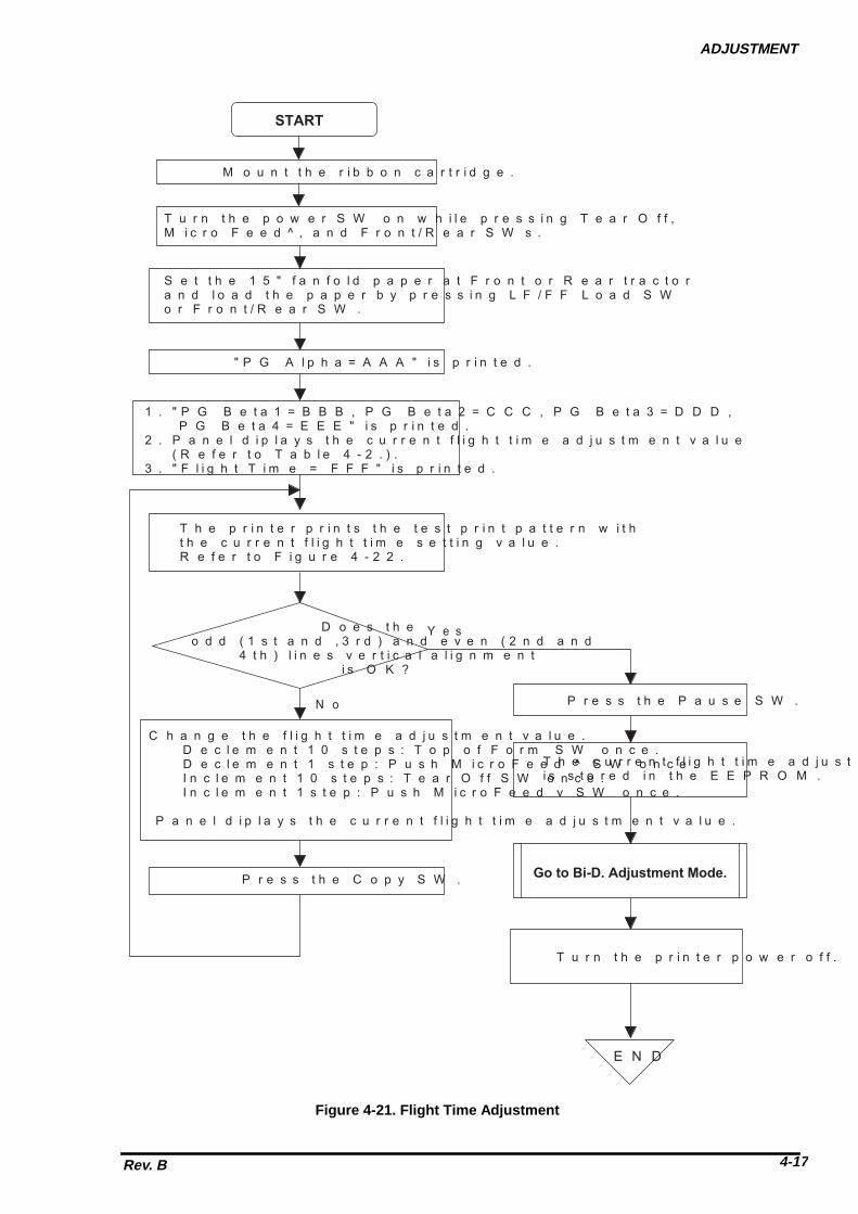
ADJUSTMENT
Rev. B 4-17
Y e s
S T A R T
T u r n t h e p o w e r S W o n w h i l e p r e s s i n g T e a r O f f , M i c r o F e e d ^ , a n d F r o n t / R e a r S W s .
S e t t h e 1 5 " f a n f o l d p a p e r a t F r o n t o r R e a r t r a c t o r a n d l o a d t h e p a p e r b y p r e s s i n g L F / F F L o a d S W o r F r o n t / R e a r S W .
" P G A l p h a = A A A " i s p r i n t e d .
1 . " P G B e t a 1 = B B B , P G B e t a 2 = C C C , P G B e t a 3 = D D D , P G B e t a 4 = E E E " i s p r i n t e d .2 . P a n e l d i p l a y s t h e c u r r e n t f l i g h t t i m e a d j u s t m e n t v a l u e ( R e f e r t o T a b l e 4 - 2 . ) .3 . " F l i g h t T i m e = F F F " i s p r i n t e d .
T h e p r i n t e r p r i n t s t h e t e s t p r i n t p a t t e r n w i t h t h e c u r r e n t f l i g h t t i m e s e t t i n g v a l u e .R e f e r t o F i g u r e 4 - 2 2 .
D o e s t h e o d d ( 1 s t a n d , 3 r d ) a n d e v e n ( 2 n d a n d 4 t h ) l i n e s v e r t i c a l a l i g n m e n t i s O K ?
C h a n g e t h e f l i g h t t i m e a d j u s t m e n t v a l u e . D e c l e m e n t 1 0 s t e p s : T o p o f F o r m S W o n c e . D e c l e m e n t 1 s t e p : P u s h M i c r o F e e d ^ S W o n c e . I n c l e m e n t 1 0 s t e p s : T e a r O f f S W o n c e . I n c l e m e n t 1 s t e p : P u s h M i c r o F e e d v S W o n c e .
P a n e l d i p l a y s t h e c u r r e n t f l i g h t t i m e a d j u s t m e n t v a l u e .
P r e s s t h e C o p y S W .
T h e c u r r e n t f l i g h t t i m e a d j u s t v a l u e i s s t o r e d i n t h e E E P R O M .
G o t o B i - D . A d j u s t m e n t M o d e .
T u r n t h e p r i n t e r p o w e r o f f .
M o u n t t h e r i b b o n c a r t r i d g e .
P r e s s t h e P a u s e S W .N o
E N D
Figure 4-21. Flight Time Adjustment

DFX-8500
Rev. B4-18
Table 4-2. LED indication and Adjustment Value ComparisonLED*1) Off On*2)
Ribbon (Bi-d. adjustment) (PG adjustment)
+ (positive) 300
(negative)400
Pause 10Top of Form 20Tear Off 30Copy 40Pitch
506070
Font
8090
7 Segment*3) 0 to 9*1) : off, : On*2) Indicates 2nd column.*3) Indicates 1st column.
4 0 C O L . 4 0 C O L .5 6 C O L .
F l i g h t T i m e + X X X
Figure 4-22. Test Print Pattern

ADJUSTMENT
Rev. B 4-19
B i - D . A d j u s t m e n t M o d e
S u p e r D r a f t P r i n t M o d e :
N o
Y e s
1 . P a n e l d i p l a y s t h e c u r r e n t B i - D . a d j u s t m e n t v a l u e .2 . P r i n t e r p r i n t s " S p e e d = A A A B i d a d j u s t = B B B " . B B B * 1 ) i s t h e c u r r e n t a d j u s t m e n t v a l u e .
D o e s t h e o d d ( 1 s t a n d , 3 r d ) a n d e v e n ( 2 n d a n d 4 t h ) l i n e s v e r t i c a l a l i g n m e n t i s O K ?
T h e p r i n t e r p r i n t s t h e t e s t p r i n t p a t t e r n w i t h t h e c u r r e n t a d j u s t m e n t v a l u e .
C h a n g e t h e B i - D . a d j u s t m e n t v a l u e . D e c l e m e n t 1 0 s t e p s : T o p o f F o r m S W o n c e . D e c l e m e n t 1 s t e p : P u s h M i c r o F e e d ^ S W o n c e . I n c l e m e n t 1 0 s t e p s : T e a r O f f S W o n c e . I n c l e m e n t 1 s t e p : P u s h M i c r o F e e d v S W o n c e .P a n e l d i p l a y s t h e c u r r e n t B i - D . a d j u s t m e n t v a l u e .
A d j u s t m e n t
R e t u r n
A d j u s t m e n t
D r a f t P r i n t M o d e :
A d j u s t m e n t
N L Q P r i n t M o d e :
A d j u s t m e n t
N o
I s i t f i n i s h e d ?
E N D
T u r n t h e p r i n t e r p o w e r o f f .
P r e s s t h e P a u s e S W .T h e c u r r e n t a d j u s t m e n t v a l u e i s s t o r e d i n t h e E E P R O M .
S u p e r D r a f tS p e e d B B B
S d r S p dD r f S p dN L Q S p d
D r a f tN L Q
* 1 )
P r e s s t h e C o p y S W .Y e s
Figure 4-23. Bi-d. Adjustment