Embed Size (px)
Citation preview

EPSON DFX-8500Service Manual
Epson America, Inc.TM-DFX8500
Service Manual

ii EPSON DFX-8500 Service Manual
FCC COMPLIANCE STATEMENTFOR AMERICAN USERS
This equipment has been tested and found to comply with the limits for a Class B digital device, pursuant to Part 15 ofthe FCC Rules. These limits are designed to provide reasonable protection against harmful interference in a residentialinstallation. This equipment generates, uses, and can radiate radio frequency energy and, if not installed and used inaccordance with the instructions, may cause harmful interference to radio and television reception. However, there isno guarantee that interference will not occur in a particular installation. If this equipment does cause interference toradio and television reception, which can be determined by turning the equipment off and on, the user is encouraged totry to correct the interference by one or more of the following measures:
• Reorient or relocate the receiving antenna.• Increase the separation between the equipment and receiver.• Connect the equipment into an outlet on a circuit different from that to which the receiver is connected.• Consult the dealer or an experienced radio/TV technician for help.
WARNING
The connection of a non-shielded equipment interface cable to this equipment will invalidate the FCC Certification ofthis device and may cause interference levels that exceed the limits established by the FCC for this equipment. It is theresponsibility of the user to obtain and use a shielded equipment interface cable with this device. If this equipment hasmore than one interface connector, do not leave cables connected to unused interfaces.
Changes or modifications not expressly approved by the manufacturer could void the user's authority to operate theprinter.
FOR CANADIAN USERS
This Class B digital apparatus meets all requirements of the Canadian Interference-Causing Equipment Regulations.
Cet appareil numérique de la classe B respecte toutes les exigences du Règlement sur le materiel brouilleur duCanada.
COPYRIGHT NOTICE
All rights reserved. No part of this publication may be reproduced, stored in a retrieval system, or transmitted in anyform or by any means, electronic, mechanical, photocopying, recording, or otherwise, without the written permission ofEpson America, Inc. No patent liability is assumed with respect to use of the information contained herein. Neither isany liability assumed for damages resulting from the use of the information contained herein. While every precautionhas been taken in the preparation of this book, Epson America, Inc., assumes no responsibility for errors andomissions.
Neither Epson America, Inc., nor its affiliates shall be liable to the purchaser of this product or third parties fordamages, losses, costs, or expenses incurred by purchaser or third parties as a result of: accident, misuse, or abuse ofthis product or unauthorized modifications, repairs, or alterations to this product.
Epson America, Inc., shall not be liable against any damages or problems arising from the use of any options or anyconsumable products other than those designated as Original EPSON Products or EPSON-Approved Products bySeiko Epson Corporation.

EPSON DFX-8500 Service Manual iii
TRADEMARKS
EPSON® and ESC/P® are registered trademarks and ESC/P 2™ and EPSON Stylus are trademarks of Seiko EpsonCorporation. MicroDot™ and Super MicroDot™ are trademarks of Epson America, Inc.
General Notice: Other product names used herein are for identification purposes only and may be trademarks of theirrespective companies. EPSON disclaims any and all rights in those marks.
Copyright © 1998 Epson America, Inc.20770 Madrona AvenueTorrance, CA 90503

iv EPSON DFX-8500 Service Manual
PRECAUTIONS
There are cautionary notes throughout the text to help you avoid personal injury or equipment damage.
WARNING
Signals a precaution which, if ignored, could result in serious or fatal personal injury. Great caution shouldbe exercised in performing procedures preceded by a WARNING heading.
CAUTION
Signals a precaution which, if ignored, could result in damage to equipment.
Always observe the measures listed below when performing repair or maintenance procedures.
WARNING
1. Always disconnect the product from both the power source and host computer before performing anymaintenance or repair procedure.
2. No work should be performed on the unit by persons unfamiliar with basic safety measures dictated forall electronics technicians in their line of work.
3. In performing testing described in this manual, do not connect the unit to a power source until instructedto do so. When the power supply cable must be connected, use extreme caution in working on thepower supply and other electronic components.
CAUTION
1. Repairs on EPSON products should be performed only by an EPSON-certified repair technician.2. Make certain that the source voltage is the same as the rated voltage listed on the serial number/rating
plate. If the EPSON product has a primary AC rating different from the available power source, do notconnect it to the power source.
3. Always verify that the EPSON product has been disconnected from the power source before removingor replacing printed circuit boards and/or individual chips.
4. To protect sensitive microprocessors and circuitry, use static discharge equipment, such as anti-staticwrist straps, when accessing internal components.
5. Replace malfunctioning components only with those components recommended by the manufacturer;introduction of second-source ICs or other nonapproved components may damage the product and voidany applicable EPSON warranty.

CHAPTER 1PRODUCT DESCRIPTION
1.1 FEATURES __________________________________________________________________ 1-1
1.2 SPECIFICATIONS____________________________________________________________ 1-3Printing Specifications _____________________________________________________________________ 1-3Paper Feeding Specifications ________________________________________________________________ 1-6Electrical Specifications ____________________________________________________________________ 1-6Environmental Specifications________________________________________________________________ 1-6Reliability _______________________________________________________________________________ 1-6Safety Approvals__________________________________________________________________________ 1-7CE Marking _____________________________________________________________________________ 1-7Acoustic Noise ___________________________________________________________________________ 1-7Ribbon Cartridge__________________________________________________________________________ 1-7Physical Specifications _____________________________________________________________________ 1-7Printable Area ____________________________________________________________________________ 1-8Paper and Media _________________________________________________________________________ 1-12
Continuous Paper (Single-sheet and Multi-sheet Forms)________________________________________ 1-12Labels _______________________________________________________________________________ 1-14Continuous Forms with Labels ____________________________________________________________ 1-15Overlapping Multi-sheet Forms ___________________________________________________________ 1-16Perforations___________________________________________________________________________ 1-16Notes ________________________________________________________________________________ 1-16
1.3 INTERFACES_______________________________________________________________ 1-19Parallel Interface (Forward Channel) _________________________________________________________ 1-19Parallel Interface (Reverse Channel) _________________________________________________________ 1-21Serial Interface __________________________________________________________________________ 1-23Optional Interface ________________________________________________________________________ 1-23Interface Selection________________________________________________________________________ 1-24Preventing Timeouts ______________________________________________________________________ 1-24
1.4 OPERATING INSTRUCTIONS________________________________________________ 1-25Control Panel ___________________________________________________________________________ 1-25
Buttons ______________________________________________________________________________ 1-26Indicators_____________________________________________________________________________ 1-27
Errors and Buzzers _______________________________________________________________________ 1-28DIP Switch Settings ______________________________________________________________________ 1-30Control Panel Functions ___________________________________________________________________ 1-34
Normal Operation ______________________________________________________________________ 1-34Advanced Control Panel Functions ________________________________________________________ 1-36Automatic Detection Functions ___________________________________________________________ 1-37
Paper Memory Functions __________________________________________________________________ 1-38Initializations ___________________________________________________________________________ 1-39
Hardware Initialization __________________________________________________________________ 1-39Software Initialization___________________________________________________________________ 1-39Panel Initialization _____________________________________________________________________ 1-39
1.5 MAIN COMPONENTS _______________________________________________________ 1-40M-3I60 Printer Mechanism ________________________________________________________________ 1-41

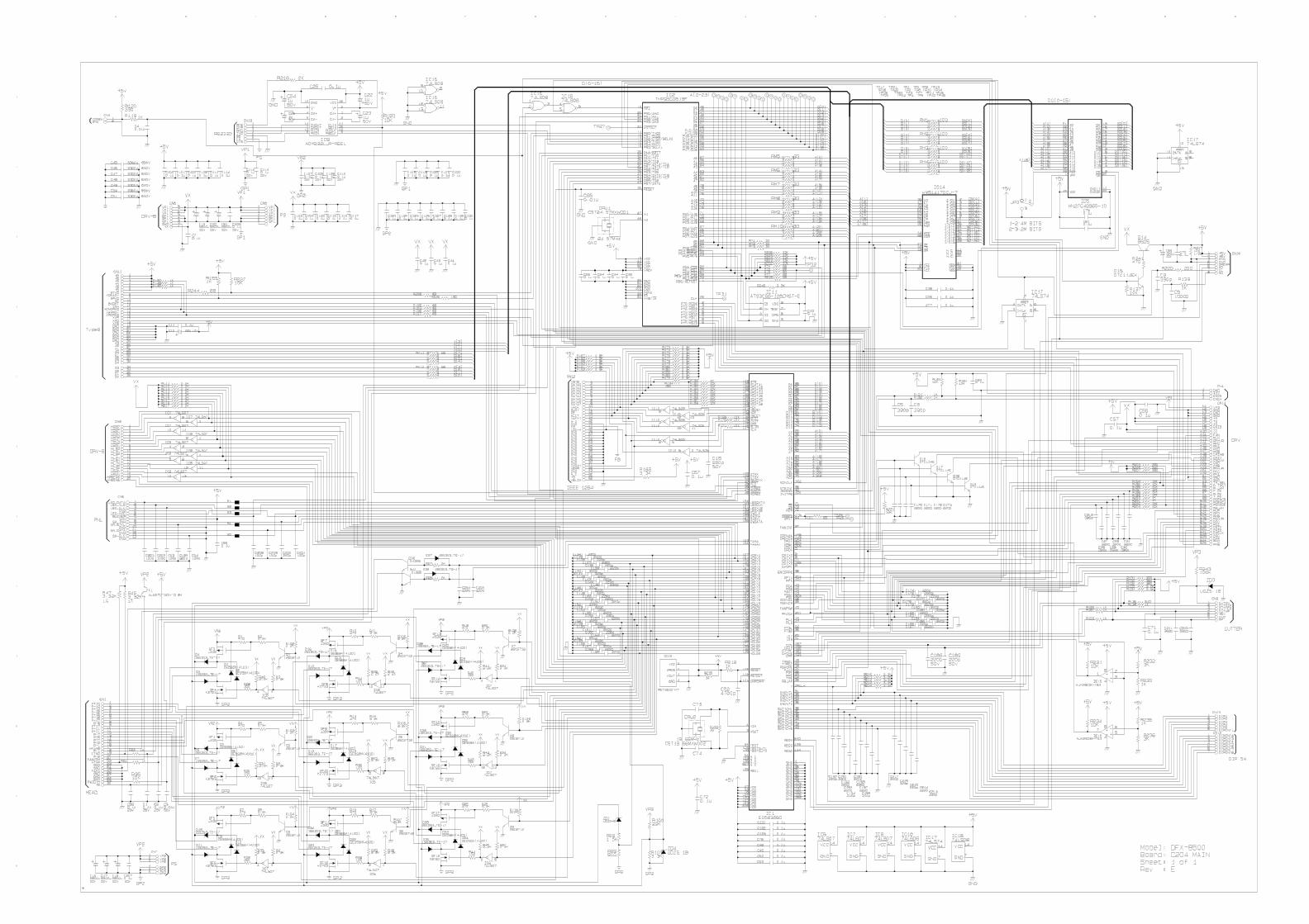
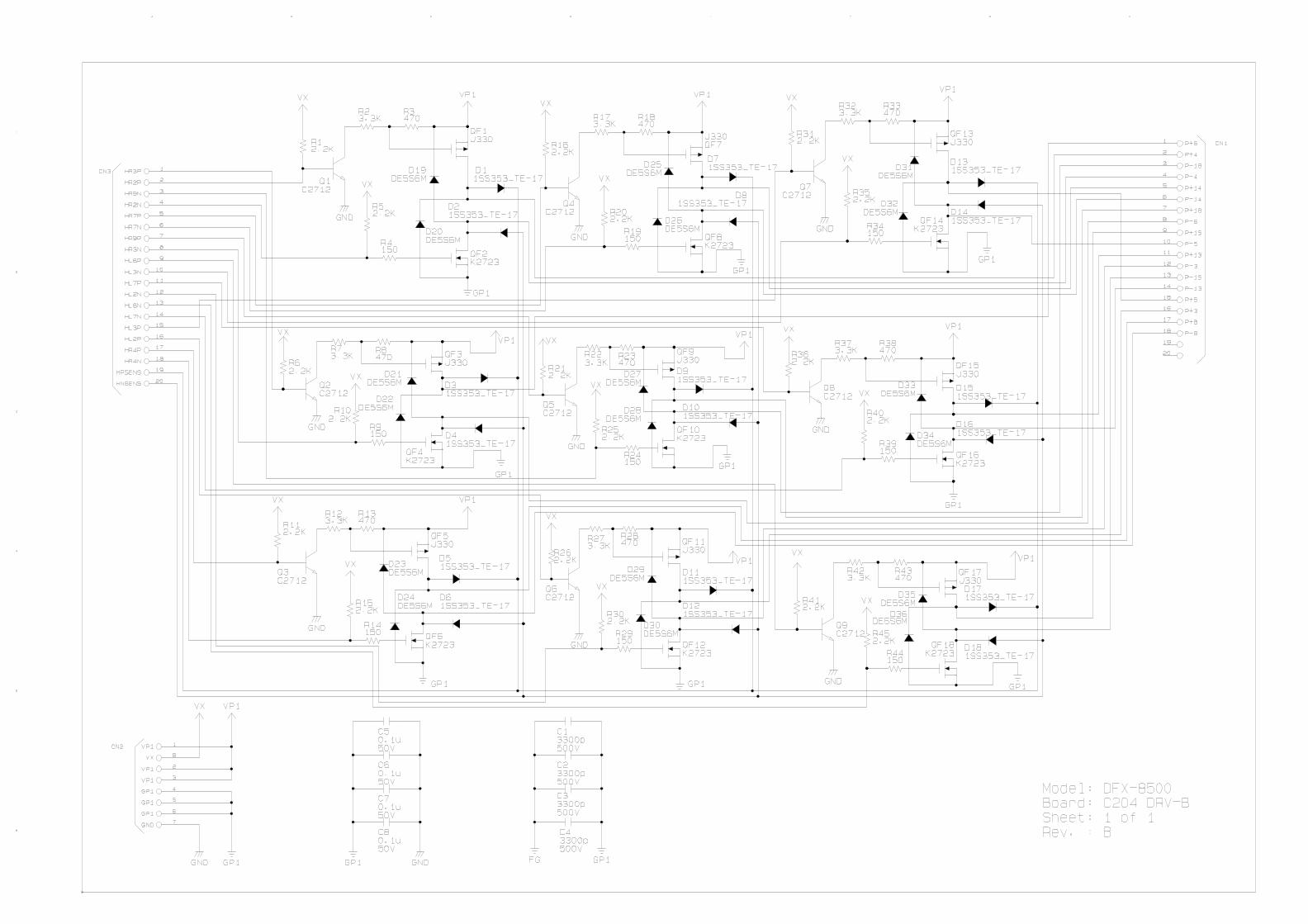
C204 Main Board_________________________________________________________________________ 1-42C204 DRV Board _________________________________________________________________________ 1-43C204 DRV-B Board _______________________________________________________________________ 1-44C204 SUB Board _________________________________________________________________________ 1-44C204 PSB/PSE Board _____________________________________________________________________ 1-45Control Panel ____________________________________________________________________________ 1-46Housing ________________________________________________________________________________ 1-46
PRODUCT DESCRIPTION
1-1
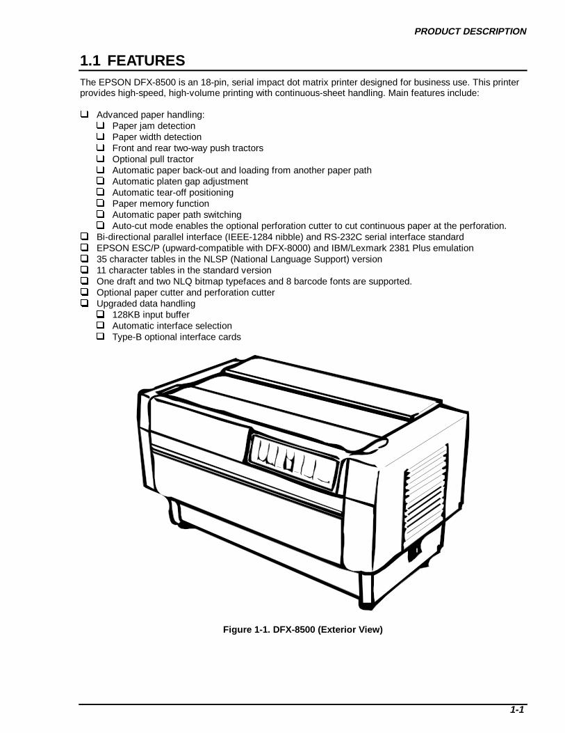
1.1 FEATURESThe EPSON DFX-8500 is an 18-pin, serial impact dot matrix printer designed for business use. This printerprovides high-speed, high-volume printing with continuous-sheet handling. Main features include:
Advanced paper handling: Paper jam detection Paper width detection Front and rear two-way push tractors Optional pull tractor Automatic paper back-out and loading from another paper path Automatic platen gap adjustment Automatic tear-off positioning Paper memory function Automatic paper path switching Auto-cut mode enables the optional perforation cutter to cut continuous paper at the perforation.
Bi-directional parallel interface (IEEE-1284 nibble) and RS-232C serial interface standard EPSON ESC/P (upward-compatible with DFX-8000) and IBM/Lexmark 2381 Plus emulation 35 character tables in the NLSP (National Language Support) version 11 character tables in the standard version One draft and two NLQ bitmap typefaces and 8 barcode fonts are supported. Optional paper cutter and perforation cutter Upgraded data handling 128KB input buffer Automatic interface selection Type-B optional interface cards
Figure 1-1. DFX- 8500 (Exterior View)

DFX-8500
1-2
The following table shows options.
Table 1-1. Options
Code Name#8766 Ribbon cartridge#8767 Ribbon pack#8309 Pull tractor#8502 Printer standC815001 Paper cutterC815071 Perforation cutterC823051 Serial interface cardC823071 32KB serial I/F cardC823121 Local Talk I/F cardC823141 Coax I/F cardC823151 Twinax I/F cardC823452 Bi-directional parallel I/F cardC823572 Multi-protocol Ethernet I/F card

PRODUCT DESCRIPTION
1-3
1.2 SPECIFICATIONSThis section contains the specifications for the DFX-8500.
PRINTING SPECIFICATIONS Print method: Impact dot matrix Number of pins: 18-pin (See Figure 1-2.) Pin arrangement: 9 x 2 Pin diameter: 0.0114 inches (0.29 mm) Color: Black Print direction: Bi-directional with logic seeking Printable columns: See Table 1-2.
0.0138 in. (0.35 mm)
0.111 in. (2.82 mm)
0.0665 in. (1.69 mm)
Figure 1-2. Printhead Pin Configuration
Table 1-2. Printable Columns
Print Mode Character Pitch Printable C olumns
High speed draft 10 cpi 136Draft 10 cpi 136
12 cpi 16315 cpi 204
Draft condensed 17 cpi 23320 cpi 272
Draft 10 cpi 136NLQ 10 cpi 136
12 cpi 16315 cpi 204
NLQ condensed 17 cpi 23320 cpi 272
DFX-8500
1-4
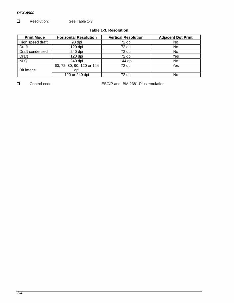
Resolution: See Table 1-3.
Table 1-3. Resolution
Print Mode Horizontal Resolution Vertical Resolution Adj acent Dot PrintHigh speed draft 90 dpi 72 dpi NoDraft 120 dpi 72 dpi NoDraft condensed 240 dpi 72 dpi NoDraft 120 dpi 72 dpi YesNLQ 240 dpi 144 dpi No
Bit image60, 72, 80, 90, 120 or 144
dpi72 dpi Yes
120 or 240 dpi 72 dpi No
Control code: ESC/P and IBM 2381 Plus emulation

PRODUCT DESCRIPTION
1-5
Character tables and typefaces: See Table 1-4.
Table 1-4. Character tables and typefacesCharacter Table Bitmap Font
Standard version Italic Table EPSON DraftPC437 (US, Standard Europe) EPSON RomanPC850 (Multilingual) EPSON Sans SerifPC860 (Portuguese)PC861 (Icelandic)PC863 (Canadian French)PC865 (Nordic)AbicompBRASCIIRoman 8ISO Latin 1
NLSP version Italic Table EPSON DraftPC437 (US, Standard Europe) EPSON RomanPC850 (Multilingual) PC437 Greek EPSON Sans SerifPC852 (East Europe) PC853 (Turkish)PC855 (Cyrillic) PC857 (Turkish)PC866 (Russian) PC869 (Greek)MAZOWIA (Poland) Code MJK (CSFR)ISO 8859-7 (Latin/Greek) ISO Latin 1T (Turkish)Bulgaria EstoniaPC 774 (LST 1283:1993) ISO 8859-2 (ISO Latin 2)PC 866 LAT. ( Latvian) PC 866 UKRPC 860 PC 861PC 865 PC APTECPC 708 PC 720PC AR864 PC 863*Abicomp* BRASCII*Roman 8* ISO Latin 1Hebrew 7* Hebrew 8*PC 862*
International USA FranceCharacter Sets Germany U.K.(both versions) Denmark 1 Sweden
Italy Spain 1Japan NorwayDenmark 2 Spain 2Latin America
Bar Codes EAN-13(both versions) EAN-8
Interleaved 2 of 5UPC-AUPC-ECode 39Code 128POSTNET
* These tables cannot be selected using DIP switches.Notes: The ESC R command works on all the character tables.
The international and legal characters are: 23h, 24h, 40h, 5Bh, 5Ch, 5Dh, 5Eh, 60h, 7Bh, 7Ch, 7Dh,and 7Eh.
Input data buffer: 0KB or 128KB (depends on DIP switch settings)
DFX-8500
1-6
PAPER FEEDING SPECIFICATIONS Feeding method: Push tractor feed (front and rear)
Push and pull tractor feed (front and rear) Feeder: Front push tractor, rear push tractor, pull tractor (option) Paper insertion side alignment: Left Paper path: Tractors (front in, rear in, top out) Line spacing: 1/6-inch, or programmable in 1/216-inch increments.
ELECTRICAL SPECIFICATIONS 120 V version:
Rated voltage: 120 VACInput voltage range: 99 to 132 VACRated frequency range: 50 to 60 HzInput frequency range: 49.5 to 60.5 HzRated current: 3.5 A (maximum 7.5 A)Power consumption: Approximately 160 W (ISO/IEC 10561 Letter pattern)
ENERGY STAR compliantInsulation resistance: 10 MΩ minimum (between AC line and chassis, 500 VDC)Dielectric strength: 1000 AC Vrms. 1 minute or
1200 AC Vrms. 1 second (between AC line and chassis) 220 - 240 V version:
Rated voltage: 220 to 240 VACInput voltage range: 198 to 264 VACRated frequency range: 50 to 60 HzInput frequency range: 49.5 to 60.5 HzRated current: 1.4 A (maximum 3.5 A)Power consumption: Approximately 160 W (ISO/IEC 10561 Letter pattern)
ENERGY STAR compliantInsulation resistance: 10 MΩ minimum (between AC line and chassis, 500 VDC)Dielectric strength: 1500 AC Vrms. 1 minute (between AC line and chassis)
ENVIRONMENTAL SPECIFICATIONS Temperature : 41 to 95 oF (5 to 35 oC) (operating)
-22 to 140 oF (-30 to 60 oC) (non-operating) Printing stops when the printhead temperature rises above the upper limit. The printer resumes printing
when the print head temperature falls below the upper limit. Humidity : 10 to 80 % RH (operating) *
5 to 85 % RH (non-operating) * Resistance to shock : 1 G, within 1 ms (operating)
2 G, within 2 ms (non-operating) †
Resistance to vibration : 0.25 G, 10 to 55 Hz (operating)0.50 G, 10 to 55 Hz (non-operating) †
* Without condensation† With shipment container
RELIABILITY Total print volume: 26 million lines (excepting the printhead) MTBF: 9,000 Power On Hours (POH) (at 25% duty) Printhead life: 400 million characters at 14 dots/character Ribbon life: 15 million characters at 14 dots/character

PRODUCT DESCRIPTION
1-7
SAFETY APPROVALS 120 V version:
Safety standards : UL1950 with D3CSA C22.2 No.950 with D3
EMI : FCC part 15 subpart B class BCSA C108.8 class B
230 V version:Safety standards : EN60950 (VDE, NEMKO)EMI: EN55022 (CISPR pub. 22) class B
AS / NZS 3548 class B
CE MARKING 230-240 V version:
Low Voltage Directive 73/23/EEC : EN60950EMC Directive 89/336/EEC : EN55022 class B EN61000-3-2 EN61000-3-3 EN50082-1 IEC801-2 IEC801-3 IEC801-4
ACOUSTIC NOISELevel: 58 dB(A) (ISO 7779 pattern)
RIBBON CARTRIDGE Type: Fabric Color: Black Ribbon life: 15 million characters (draft 10 cpi, 14 dots/character) Dimensions: 19.9 (W) × 4.86 (D) × 0.91 (H) in.
[506.0 (W) × 123.5 (D) × 23.0 (H) mm]
PHYSICAL SPECIFICATIONS Dimensions: 27.6 (W) × 15.0 (D) × 14.5 (H) in.
[700 (W) × 382 (D) × 369 (H) mm] Weight: Approximately 64 lb. (29 kg)
DFX-8500
1-8
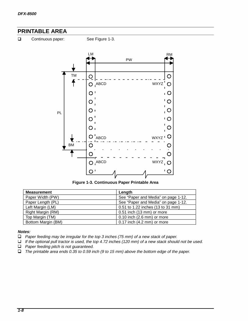
PRINTABLE AREA Continuous paper: See Figure 1-3.
WXYZABCD
ABCD WXYZ
ABCD WXYZ
LM RM
BM
TM
PL
PW
Figure 1-3. Continuous Paper Printable Area
Measurement LengthPaper Width (PW) See “Paper and Media” on page 1-12.Paper Length (PL) See “Paper and Media” on page 1-12.Left Margin (LM) 0.51 to 1.22 inches (13 to 31 mm)Right Margin (RM) 0.51 inch (13 mm) or moreTop Margin (TM) 0.10 inch (2.6 mm) or moreBottom Margin (BM) 0.17 inch (4.2 mm) or more
Notes: Paper feeding may be irregular for the top 3 inches (75 mm) of a new stack of paper. If the optional pull tractor is used, the top 4.72 inches (120 mm) of a new stack should not be used. Paper feeding pitch is not guaranteed. The printable area ends 0.35 to 0.59 inch (9 to 15 mm) above the bottom edge of the paper.
PRODUCT DESCRIPTION
1-9
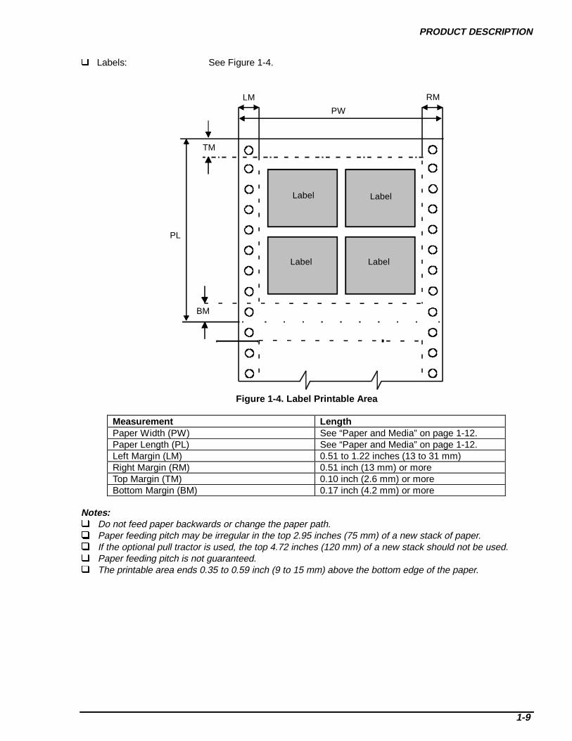
Labels: See Figure 1-4.
LM RM
BM
TM
PL
PW
Label Label
Label Label
Figure 1-4. Label Printable Area
Measurement LengthPaper Width (PW) See “Paper and Media” on page 1-12.Paper Length (PL) See “Paper and Media” on page 1-12.Left Margin (LM) 0.51 to 1.22 inches (13 to 31 mm)Right Margin (RM) 0.51 inch (13 mm) or moreTop Margin (TM) 0.10 inch (2.6 mm) or moreBottom Margin (BM) 0.17 inch (4.2 mm) or more
Notes: Do not feed paper backwards or change the paper path. Paper feeding pitch may be irregular in the top 2.95 inches (75 mm) of a new stack of paper. If the optional pull tractor is used, the top 4.72 inches (120 mm) of a new stack should not be used. Paper feeding pitch is not guaranteed. The printable area ends 0.35 to 0.59 inch (9 to 15 mm) above the bottom edge of the paper.

DFX-8500
1-10
Continuous forms with labels: See Figure 1-5.
ABCD WXYZ
LM RM
BM
TM
PL
PW
Printable Area
LOL ROLLabel
BOL
TOL
LFL RFL
Label
BFL
TFL
Label
Non Printable Area
Figure 1-5. Continuous Fo rms with Labels Printable Area
Measurement LengthPaper Width (PW) See “Paper and Media” on page 1-12.Paper Length (PL) See “Paper and Media” on page 1-12.Left Margin (LM) 0.51 to 1.22 inches (13 to 31 mm)Right Margin (RM) 0.51 inch (13 mm) or moreTop Margin (TM) 0.10 inch (2.6 mm) or moreBottom Margin (BM) 0.17 inch (4.2 mm) or moreLeft Margin from Label (LFL) 2.6 inches (65 mm) or moreRight Margin from Label (RFL) 2.6 inches (65 mm) or moreTop Margin from Label (TFL) 0.49 inch (12.5 mm) or moreBottom Margin from Label (BFL) 0.49 inch (12.5 mm) or moreLeft Margin on Label (LOL) 0.2 inch (5 mm) or moreRight Margin on Label (ROL) 0.2 inch (5 mm) or moreTop Margin on Label (TOL) 0.08 inch (2 mm) or moreBottom Margin on Label (BOL) 0.08 inch (2 mm) or more
Notes: Do not feed paper backwards or change the paper path. Paper feeding pitch may be irregular in the top 2.95 inches (75 mm) of a new stack of paper. If the optional pull tractor is used, the top 4.72 inches (120 mm) of a new stack should not be used. Paper feeding pitch is not guaranteed. The printable area ends 0.35 to 0.59 inch (9 to 15 mm) above the bottom edge of the paper.
PRODUCT DESCRIPTION
1-11
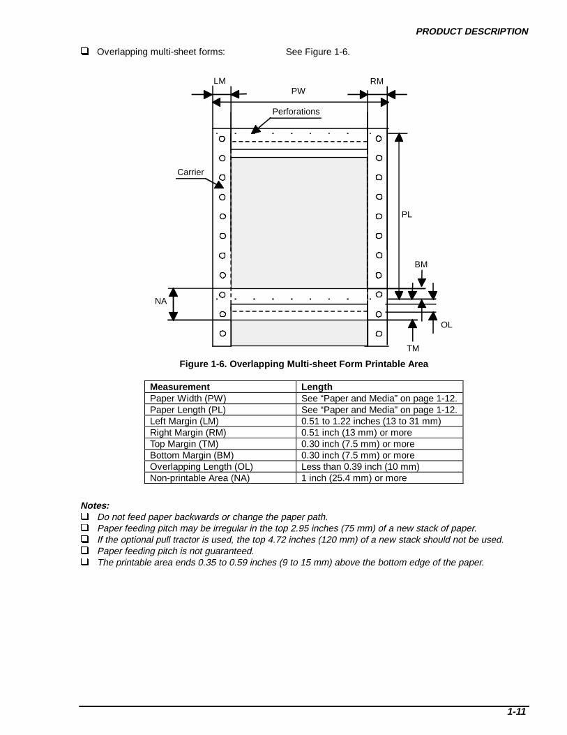
Overlapping multi-sheet forms: See Figure 1-6.
LM
Perforations
Carrier
PW
PL
NA
OL
BM
TM
RM
Figure 1-6. O verla pping Multi-sheet Form Printable Area
Measurement LengthPaper Width (PW) See “Paper and Media” on page 1-12.Paper Length (PL) See “Paper and Media” on page 1-12.Left Margin (LM) 0.51 to 1.22 inches (13 to 31 mm)Right Margin (RM) 0.51 inch (13 mm) or moreTop Margin (TM) 0.30 inch (7.5 mm) or moreBottom Margin (BM) 0.30 inch (7.5 mm) or moreOverlapping Length (OL) Less than 0.39 inch (10 mm)Non-printable Area (NA) 1 inch (25.4 mm) or more
Notes: Do not feed paper backwards or change the paper path. Paper feeding pitch may be irregular in the top 2.95 inches (75 mm) of a new stack of paper. If the optional pull tractor is used, the top 4.72 inches (120 mm) of a new stack should not be used. Paper feeding pitch is not guaranteed. The printable area ends 0.35 to 0.59 inches (9 to 15 mm) above the bottom edge of the paper.

DFX-8500
1-12
PAPER AND MEDIA
Continuous Paper (Single-sheet and Multi-sheet Forms)
Table 1-5. Continuous Paper
Measurement Units Front Path Rear PathMinimum Maximum Minimum Maximum
Width inchesmm
4.0101
16.0406
4.0101
16.0406
Length inchesmm
4.0101
17.0431
4.0101
17.0431
Copies 1 original + 6 copies 1 original + 5 copiesTotal Thickness inches
mm0.00250.065
0.0210.53
0.00250.065
0.0180.46
Weight(single sheet)
lbsg/m2
1452.6
2282.7
1452.6
2282.7
Weight(multiple sheet)
lbsg/m2
1141.4
1556.4
1141.4
1556.4
Quality Plain paper, recycled paper, and carbonless multi-sheet formsMulti-sheet binding Roughly bound multi-sheet forms can cause paper jams.
Multi-sheet forms should be held together by spot gluing, paper-stapling,or tape stitching. Spot gluing is recommended for the best printing quality.
Spot glue must be applied on both sides of the paper. (See Figure 1-7.) Spot glued parts must be pressed flat. There must be no creases in the
paper. Paper staples must be applied from the front; the paper must be flat. (See
Figure 1-8.) Paper staples must be able to feed through the printer in both directions.
(See Figure 1-9.) Paper staples must be flat. (See Figure 1-10.) Never use metal staples. The bindings must be outside the printable area. Multi-sheet forms should be bound firmly to each other; the binding must
not be too wide or thick.Perforations See “Perforations” on page 1-16.Notes See “Notes” on page 1-16.
Figure 1-7. Spot Glue Positioning

PRODUCT DESCRIPTION
1-13
Figure 1-8. Paper Stapling Height
Figure 1-9. Paper Stapling, Method 1
Figure 1-10. Paper Stapling, Method 2
DFX-8500
1-14
Labels
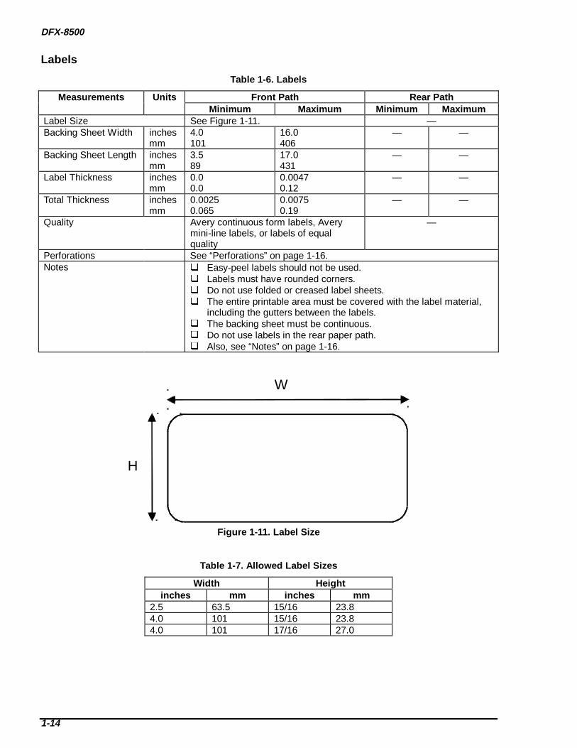
Table 1-6. Labels
Measurements Units Front Path Rear PathMinimum Maximum Minimum Maximum
Label Size See Figure 1-11. —Backing Sheet Width inches
mm4.0101
16.0406
— —
Backing Sheet Length inchesmm
3.589
17.0431
— —
Label Thickness inchesmm
0.00.0
0.00470.12
— —
Total Thickness inchesmm
0.00250.065
0.00750.19
— —
Quality Avery continuous form labels, Averymini-line labels, or labels of equalquality
—
Perforations See “Perforations” on page 1-16.Notes Easy-peel labels should not be used.
Labels must have rounded corners. Do not use folded or creased label sheets. The entire printable area must be covered with the label material,
including the gutters between the labels. The backing sheet must be continuous. Do not use labels in the rear paper path. Also, see “Notes” on page 1-16.
W
H
Figure 1-11. Label Size
Table 1-7. Allowed Label Sizes
Width Heightinches mm inches mm
2.5 63.5 15/16 23.84.0 101 15/16 23.84.0 101 17/16 27.0

PRODUCT DESCRIPTION
1-15
Continuous Forms with Labels
Table 1-8. Continuous Fo rms with Labels
Measurements Units Front Path Rear PathMinimum Maximum Minimum Maximum
Label Size See “Labels” on page 1-14. —Width inches
mm4.0101
16.0406
— —
Length inchesmm
4.0101
17.0431
— —
Weight(single sheet)
lbsg/m2
1452.6
2282.7
— —
Weight(multiple sheet)
lbsg/m2
1141.4
1556.4
— —
Label Thickness inchesmm
0.00.0
0.00470.12
— —
Total Thickness inchesmm
0.00250.065
0.0210.53
— —
Quality (Multi-sheet forms) Plain paper, recycled paper, andcarbonless multi-sheet forms
—
Quality (Label) Avery continuous form labels, Averymini-line labels, or labels of equalquality
—
Multi-sheet binding Roughly bound multi-sheet forms can cause paper jams. Multi-sheet forms should be held together by spot gluing, paper-stapling,
or tape stitching. Spot gluing is recommended for the best printing quality. Spot glue must be applied on both sides of the paper. (See Figure 1-7.) Spot glued parts must be pressed flat. There must be no creases in the
paper. Paper staples must be applied from the front; the paper must be flat. (See
Figure 1-8.) Paper staples must be able to feed through the printer in both directions.
(See Figure 1-9.) Paper staples must be flat. (See Figure 1-10.) Never use metal staples. The bindings must be outside the printable area. Multi-sheet forms should be bound firmly to each other; the binding must
not be too wide or thick.Perforations See “Perforations” on page 1-16.Notes Easy-peel labels should not be used.
Labels must have rounded corners. Do not use folded or creased label sheets. The entire printable area must be covered with the label material,
including the gutters between the labels. The backing sheet must be continuous. Do not use labels with the rear paper path. Also, see “Notes” on page 1-16.

DFX-8500
1-16
Overlapping Multi-sheet Forms
Table 1-9. Overla pping Multi-sheet Forms
Measurement Units Front Entry Rear EntryMinimum Maximum Minimum Maximum
Width inchesmm
4.0101
16.0406
- -
Length inchesmm
4.0101
17.0431
- -
Weight(single sheet)
lbsg/m2
1452.6
2282.7
- -
Weight(multiple sheet)
lbsg/m2
1141.4
1556.4
- -
Copies 1 original + 5 copies + 1 backingsheet
-
Total Thickness(print area)
inchesmm
0.00250.065
0.0210.53
- -
Total Thickness(overlap area)
inchesmm
0.0050.13
0.0280.70
- -
Overlapping Length inchesmm
more than 0more than 0
0.3910
- -
Quality (multi-sheet forms) Plain paper, recycled paper, andcarbonless multi-sheet forms
-
Multi-sheet binding Multi-sheet paper must be bound at the top with spot gluing. (See Figure 1-12.) The binding must be outside the printable area. Multi-sheet forms should be bound firmly to each other; the binding must not be
too wide or thick.Perforation See “Perforations” below.Notes Overlapping multi-sheet forms must be inserted into the front entrance.
Also see “Notes” below.
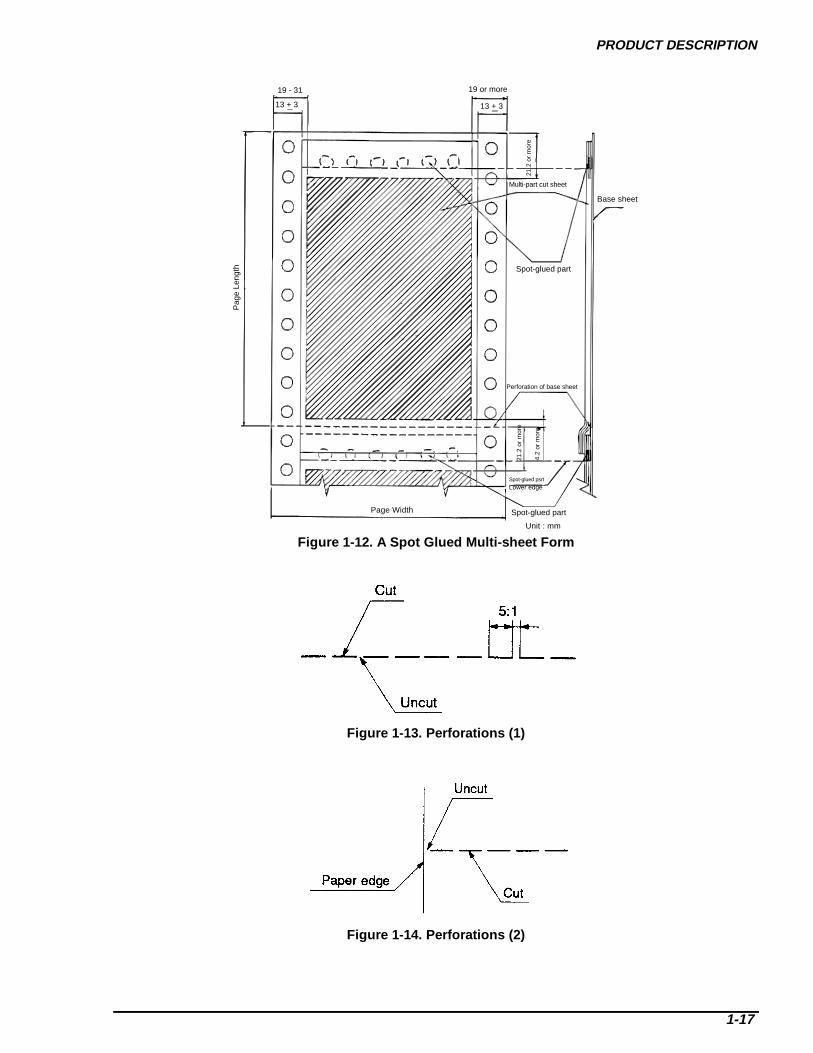
Perforations Weak horizontal and vertical perforations may cause paper jams. The ratio of the perforation length to the distance between perforations must be between 3 and 5. (See
Figure 1-13.) Sheet edges must be uncut. (See Figure 1-14.) Horizontal and vertical perforations must not cross. (See Figure 1-15.) The perforation must be raised no more than 0.04 inch (1 mm) from the surrounding sheet surface. (See
Figure 1-16.)
Notes Use clean paper with no folds, creases, or tears. (See Figure 1-17.) The sprocket holes must be round. The holes may have teeth. (See Figure 1-18.) The sprocket holes must be in the same location on each sheet. (See Figure 1-19.) Punched out bits of paper must be removed before printing. Paper should be fan-folded at horizontal perforations. Never use paper that is not fan-folded properly.
(See Figure 1-20.) The printable area must be free of holes.
PRODUCT DESCRIPTION
1-17
19 - 31
13 + 3
Pag
e Le
ngth
Page Width Spot-glued part
Lower edgeSpot-glued psrt
Perforation of base sheet
4.2
or m
ore
21.2
or
mor
e
Spot-glued part
Base sheet
Multi-part cut sheet
21.2
or
mor
e
13 + 3
19 or more
Unit : mm
Figure 1-12. A Spot Glued Multi-sheet Form
Figure 1-13. Perforations (1)
Figure 1-14. Perforations (2)

DFX-8500
1-18
Figure 1-17. E xamples of Unsuitable Paper
a) b) c)
Figure 1-15. Perforations (3)
Figure 1-18. Spro cket Holes (1)
Figure 1-19. Spro cket Holes (2)
Figure 1-16. Raised Perforation
Figure 1-20. Inco rrectly Folded Paper

PRODUCT DESCRIPTION
1-19
1.3 INTERFACES The DFX-8500 has a parallel interface, a serial interface, and a slot for an optional Type-B interface card.
This section presents the specifications for each interface type.
PARALLEL INTERFACE (FORWARD CHANNEL) Data transmission mode: 8-bit parallel, IEEE-1284 compatible mode Synchronization: /STROBE pulse Connector type: 57-30360 (AMPHENOL) 36-pin plug or equivalent Handshaking: BUSY and /ACK handshakingNote: The BUSY signal is set HIGH before setting either /ERROR low or PE high. The BUSY signal is held
HIGH until all these signals return to their inactive state. The BUSY signal is HIGH in the following cases: During data entry (see data transmission timing below) When the input data buffer is full When the /INIT signal is at a low level During hardware initialization During printer errors (see /ERROR signal) While printing a self-test or DIP switch settings When the parallel interface is not selected
Note: The /ERROR signal is set LOW when the printer is in one of the following states: Printer hardware error (fatal error) Paper out error Paper jam error The cover is open Paper change incomplete error Paper size error Ribbon jam error
Note: The PE signal is set HIGH during paper out errors.
Data transmission timing: See Figure 1-21 below.
DATA
STROBE
BUSY
ACKNLG
tsetup
tready
tbusy
tstb
treply tacktnbusy
tnex t
thold
DATA (n) DATA (n+1)
Figure 1-21. Data Transmission Timing

DFX-8500
1-20
Table 1-10. Data Transmission Timing
Parameter M inimum Maximum P arameter M inimum Maximumtsetup 500 ns — tack 500 ns 10 usthold 500 ns — tnbusy 0 —tstb 500 ns — tnext 0 —tready 0 — tt-out * — 120 nstbusy — 500 ns tt-in ** — 200 nstreply — —
* Rise and fall time of output signals. ** Rise and fall time of input signals.
Signal Level: TTL-level compatible, IEEE-1284 level 1 deviceSee Table 1-11 below.
Table 1-11. Signal L evelParameter M inimum Maximum ConditionVOH* — 5.5 VVOL* –0.5 V —IOH* — 0.32 mA VOH = 2.4 VIOL* — 12 mA VOL = 0.4 VCO — 50 pFVIH — 2.0 VVIL 0.8 V —IIH — 0.32 mA VIH = 2.4 VIIL — 12 mA VIL = 0.8 VCI — 50 pF
* A low logic level is 2.0 V or less; a high logic level is 3.0 V or more. The receiver shall provide animpedance equivalent to 7.5 kΩ to ground.

PRODUCT DESCRIPTION
1-21
Connector pin assignments and signals: See Table 1-12 below.
Table 1-12. Signal and Connector Pin Assignment (Forward channel)
Pin No. Signal Name Return GND pin I/O* Description1 /STROBE 19 I The strobe pulse. Reads in data at the falling
edge of this pulse.2-9 DATA 0-7 20-27 I The DATA 0 through DATA 7 signals represent
data bits 0 to 7, respectively. Each signal isHIGH when data is 1 and LOW when data is 0.
10 /ACKNLG 28 O This signal is a negative pulse indicating thatthe printer can again accept data.
11 BUSY 29 O A high signal indicates that the printer cannotreceive data.
12 PE 28 O A high signal indicates a paper-out error.13 SLCT 28 O Always at high level when the printer is
powered on.14 /AFXT 30 I Not used.31 /INIT 30 I The falling edge of a negative pulse or a low
signal on this line causes the printer toinitialize. A minimum 50-µs pulse is necessary.
32 /ERROR 29 O A low signal indicates a printer error.36 /SLIN 30 I Not used.18 Logic H - O Pulled up to +5 V via a 3.9 kΩ resistor.35 +5 V - O Pulled up to +5 V via a 3.3 kΩ resistor.17 Chassis GND - - Chassis GND.16,33,19,30 GND - - Signal GND.15,34 NC - - Not connected.
* From the printer’s point of view.
PARALLEL INTERFACE (REVERSE CHANNEL) Data transmission mode: IEEE-1284 nibble mode Connector type: 57-30360 (AMPHENOL) 36-pin plug or equivalent Synchronization: See the IEEE-1284 specification. Handshaking: See the IEEE-1284 specification. Data transmission timing: See the IEEE-1284 specification. Signal level: TTL-level compatible, IEEE-1284 level 1 device Extensibility request: When the printer receives the hexadecimal signals 00h or 04h, it
responds in the following manner:00h: The printer enters reverse channel mode, allowing data to be sent tothe host.04h: The printer sends the device ID to the host.
Device ID: [00h][3Ah]MPG: EPSON;CMD: ESCP9, PRPII9, BDC;MDL: DFX-8500;CLS: PRINTER
DFX-8500
1-22
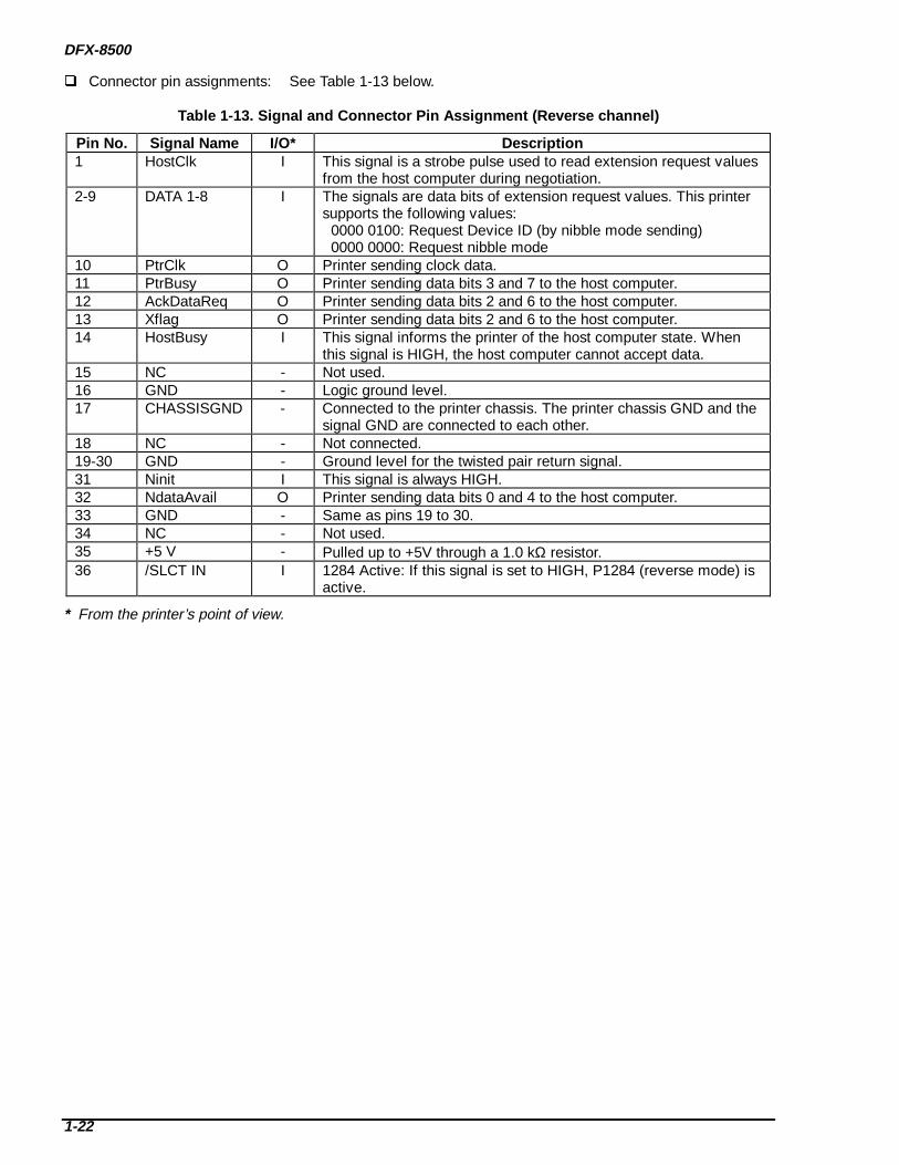
Connector pin assignments: See Table 1-13 below.
Table 1-13. Signal and Connector Pin Assignment ( Reverse channel)
Pin No. Signal Name I/O* Description1 HostClk I This signal is a strobe pulse used to read extension request values
from the host computer during negotiation.2-9 DATA 1-8 I The signals are data bits of extension request values. This printer
supports the following values: 0000 0100: Request Device ID (by nibble mode sending) 0000 0000: Request nibble mode
10 PtrClk O Printer sending clock data.11 PtrBusy O Printer sending data bits 3 and 7 to the host computer.12 AckDataReq O Printer sending data bits 2 and 6 to the host computer.13 Xflag O Printer sending data bits 2 and 6 to the host computer.14 HostBusy I This signal informs the printer of the host computer state. When
this signal is HIGH, the host computer cannot accept data.15 NC - Not used.16 GND - Logic ground level.17 CHASSISGND - Connected to the printer chassis. The printer chassis GND and the
signal GND are connected to each other.18 NC - Not connected.19-30 GND - Ground level for the twisted pair return signal.31 Ninit I This signal is always HIGH.32 NdataAvail O Printer sending data bits 0 and 4 to the host computer.33 GND - Same as pins 19 to 30.34 NC - Not used.35 +5 V - Pulled up to +5V through a 1.0 kΩ resistor.36 /SLCT IN I 1284 Active: If this signal is set to HIGH, P1284 (reverse mode) is
active.
* From the printer’s point of view.
PRODUCT DESCRIPTION
1-23
SERIAL INTERFACE Synchronization: Asynchronous Signal level (ELA-232D):
MARK (logical 1): –3 V to –25 VSPACE (logical 0): +3 V to +25 V
Word length:Start bit: 1 bitData bit: 8 bitParity bit: Odd, Even, None, or IgnoreStop bit: 1 bit or more
Baud rate: 2400, 4800, 9600 or 19200 bps Handshaking: DTR signal or X-ON / X-OFF
DTR=MARK, X-OFF: Indicates that the printer cannot receive data.DTR=SPACE, X-ON: Indicates that the printer is ready to receive data.
Note: The DTR signal MARK, X-OFF (DC3, 13h) is transmitted when the input buffer reaches 256 bytes.The DTR signal SPACE, X-ON (DC1, 11h) is transmitted when the input buffer falls below 256 bytes. Error handling: When a parity error is detected, the received byte is changed to the "*"
character code and a string of asterisks is printed. Overrun and framing errors are ignored.
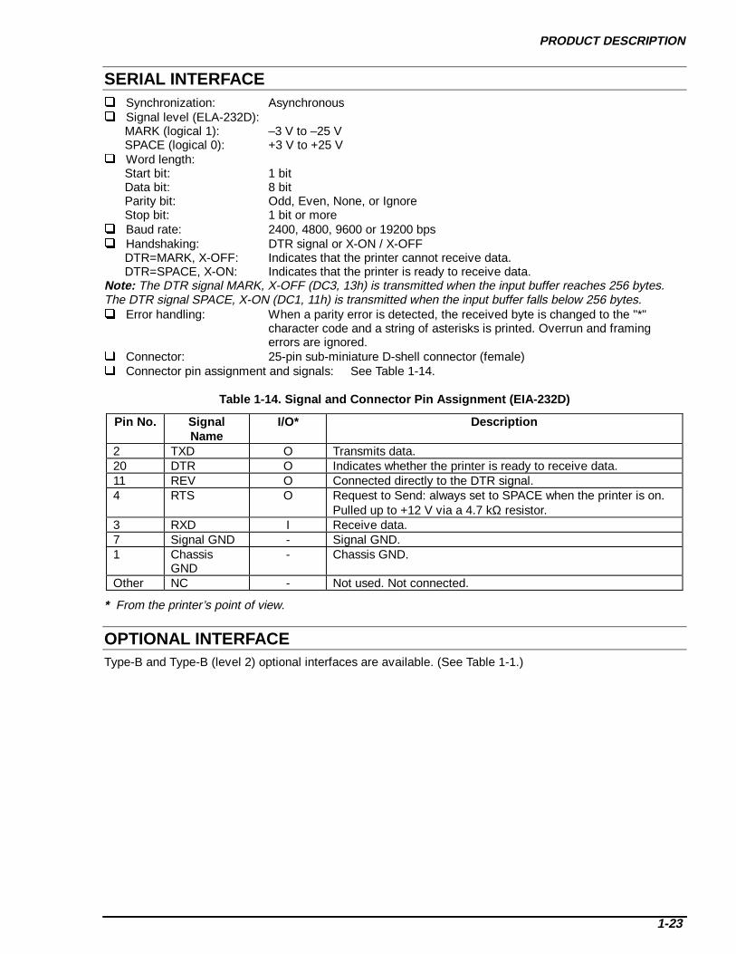
Connector: 25-pin sub-miniature D-shell connector (female) Connector pin assignment and signals: See Table 1-14.
Table 1-14. Signal and Connector Pin Assignment (EIA- 232D)
Pin No. SignalName
I/O* Description
2 TXD O Transmits data.20 DTR O Indicates whether the printer is ready to receive data.11 REV O Connected directly to the DTR signal.4 RTS O Request to Send: always set to SPACE when the printer is on.
Pulled up to +12 V via a 4.7 kΩ resistor.3 RXD I Receive data.7 Signal GND - Signal GND.1 Chassis
GND- Chassis GND.
Other NC - Not used. Not connected.
* From the printer’s point of view.
OPTIONAL INTERFACEType-B and Type-B (level 2) optional interfaces are available. (See Table 1-1.)

DFX-8500
1-24
INTERFACE SELECTIONThe printer has three interfaces: parallel, serial, and optional Type-B. These interfaces are selectedautomatically or manually using DIP switches.
Manual selection: One of three interfaces can be selected using DIP switches. Automatic selection:
If the automatic interface is selected using DIP switch settings, the printer is initialized to an idlestate, scanning all interfaces to see which receives data first. The interface that receives data firstbecomes active. When the host stops data transfer, and the printer is in stand-by state for the timespecified by the DIP switch settings, the printer returns to the idle state. As long as the host keepssending data or the printer interface is in a busy state, the selected interface remains selected.
Interface state and interface selection:When the parallel interface is not selected, the interface enters a busy state.When the serial interface is not selected, the interface sends the DTR signal MARK, X-OFF.When the optional interface is not selected, the printer sends disable commands to the optionalinterface.When the printer is initialized or returned to the idle state, the parallel interface enters a ready state,the serial interface sends DTR signal SPACE, X-ON, and the printer sends enable commands to theoptional interface.
Note: Interrupt signals (such as an /INIT signal for the parallel interface) are not effective while thetarget interface is not selected.
PREVENTING TIMEOUTSHosts abandon data transfer to peripherals when a peripheral is in a busy state for some time. To preventhosts from timing out, the printer receives data very slowly, at a rate of several bytes per minute, even if theprinter is in a busy state. This slowdown begins when the input buffer grows to several hundred bytes.Eventually, if the input buffer fills completely, the printer enters a continuously busy state.
PRODUCT DESCRIPTION
1-25
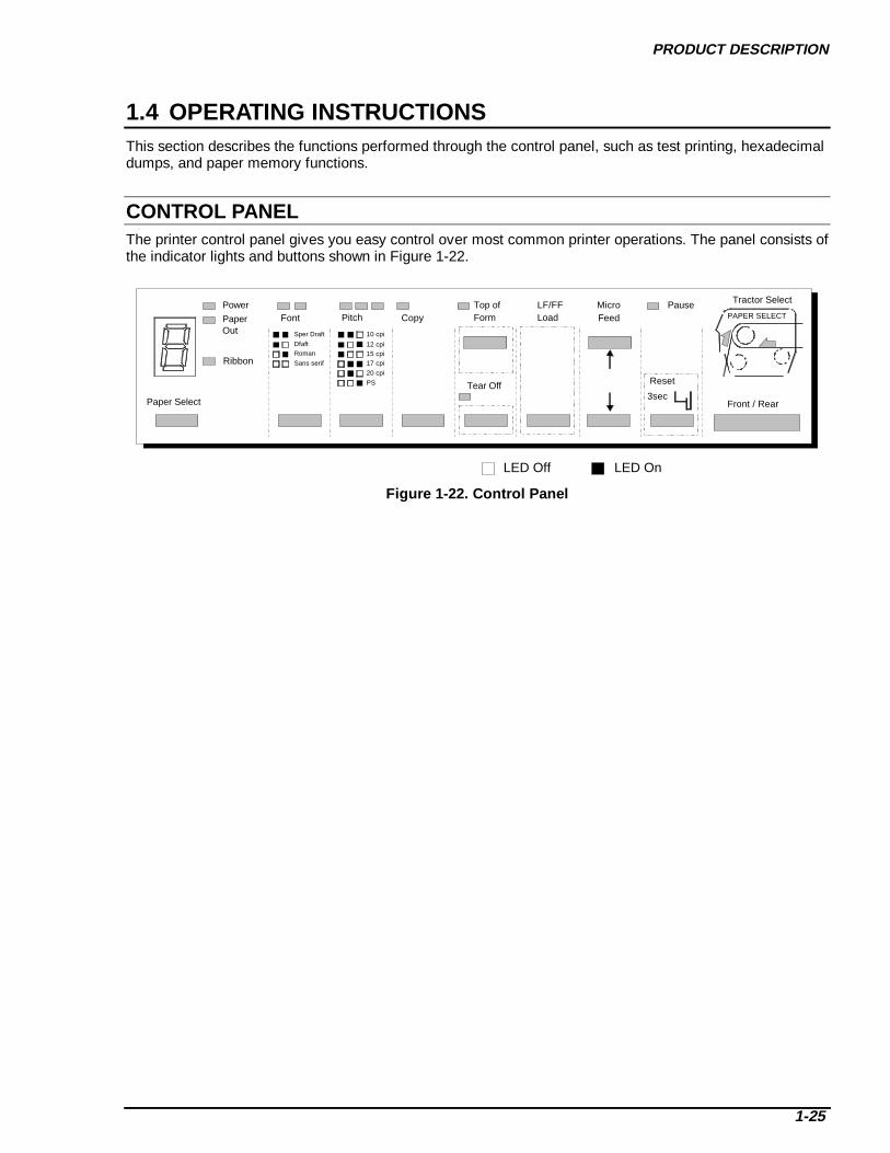
1.4 OPERATING INSTRUCTIONSThis section describes the functions performed through the control panel, such as test printing, hexadecimaldumps, and paper memory functions.
CONTROL PANELThe printer control panel gives you easy control over most common printer operations. The panel consists ofthe indicator lights and buttons shown in Figure 1-22.
Paper Select
Power
PaperOut
Ribbon
Font Pitch CopyTop ofForm
Tear Off
LF/FFLoad
Pause
Reset
3sec
Tractor Select
PAPER SELECT
Front / Rear
Sper Draft
DfaftRoman
Sans serif
10 cpi
12 cpi15 cpi17 cpi
20 cpi
PS
MicroFeed
LED Off LED On
Figure 1-22. Control Panel

DFX-8500
1-26
ButtonsThe control panel contains eleven buttons.
Button Functions during No rmal Operat ion:During normal operation, control panel buttons perform the following functions. (See Table 1-15.)
Table 1-15. Button Functions during No rmal Operation
Button FunctionFront/Rear Toggles between the front and rear paper paths.Pause Toggles between printing and paused status.
Holding this button down for three seconds resets the printer.Micro Feed ↑ Feeds paper forward 1/216 inch.Micro Feed ↓ Feeds paper backward 1/216 inch.LF/FF Load Loads the paper when the printer is empty.
Pressing this button feeds paper forward one line. Holding this button down for a few seconds feeds paper forward one
page.TOF (top of form) Allows top of form position adjustment.
Allows loading position adjustment when pressed just after loadingpaper.
Tear Off Advances continuous paper to the tear-off position.Copy Toggles between multi-form copy and normal printing.Pitch Selects pitch.Font Selects font.Paper Select Selects memorized paper setting.
Operat ion with the Power Button:Control panel buttons perform the functions shown in Table 1-16 when pressed at the same time as thePower button.
Table 1-16. Button Function when Combined with the Power Button
Button FunctionLF/FF Load Draft self testTear Off NLQ self testTear Off and LF/FF Hex dumpPause DIP switch setting printoutLF/FF Load, Micro Feed ↓ and Pause* Clear EEPROM area 2Pause and Front/Rear† Clear EEPROM area 1Copy Clear ribbon counterPaper Select This button is used for paper memory storage and
recall. See “Paper Memory Functions” on page 1-38.
Tear Off, Micro Feed ↑, and Front/Rear Flight time adjustment (See Chapter 4.)Tear Off, Micro Feed ↓, and Front/Rear Platen gap adjustment (See Chapter 4.)Micro Feed ↑ and Micro Feed ↓ Sets printable area.
Note: For details, see “Advanced Control Panel Functions” on page 1-36.* All mechanism adjustment values are cleared. The printer mechanism adjustment must be performed after
this. (See Chapter 4.)† All user setting values are replaced with the factory setting values.

PRODUCT DESCRIPTION
1-27
IndicatorsThe control panel contains fifteen LEDs.
Rear (2) (Green / Red):Green: The rear paper path is selected and has paper in it.Red: The rear paper path is selected has no paper in it.Off: The front paper path is selected.
Front (2) (Green / Red):Green: The front paper path is selected and has paper in it.Red: The front paper path is selected and has no paper in it.Off: The rear paper path is selected.
Pause (Orange):On: The printer is paused.Off: The printer is not paused.Blinking: The printhead is too hot.
Top of Form (Green):On: The top of form and tear-off positions are adjustable.
Tear Off (Green):On: The paper is at the tear-off position.Off: The paper is not at the tear-off position.
Copy (Green):On: Copy mode.Off: Normal mode.
Pitch (Green):The current pitch selection is displayed on three LEDs: : 10 cpi : 12 cpi : 15 cpi : 17 cpi : 20 cpi : PS (: LED off, : LED on.)
Font (Green):The current font selection is displayed on two LEDs: : Super draft : Draft : Roman : Sans Serif (: LED off, : LED on.)
Power (Green):On: The printer is on.Off: The printer is off.
Paper Out (Red):On: The printer is out of paper.Blinking: There is a paper jam.
Ribbon (Red):Blinking: There is a ribbon jam.
Paper Select (7-segment, Green):This LED indicates the selected paper size number and displays error codes.

DFX-8500
1-28
ERRORS AND BUZZERSErrors fall into 2 types: normal errors/warnings and fatal errors. See the tables below for detailedinformation. See Chapter 5 for more information about errors and troubleshooting.
Table 1-17. Error/Warning Beeper Information
Error/Warning PauseLED
Paper OutLED
RibbonLED
Beeper Description
Printhead hot Blinking Off Off —Printhead fan hot Blinking Off Off —Paper out On On Off . . . This error occurs when the
printer fails to load a sheet.(Three 100-ms beeps with a100-ms interval.)
Cover open ON Off Off . . . This error occurs when theprinter’s cover is open.
Paper changeincomplete
On Off Off . . . This error occurs when theprinter fails to change the paper.
Paper backfeedincomplete
On Blinking Off . . .
Paper size error ON Off Off . . . This error occurs when the setpaper width and the currentpaper size are different.
Paper jam ON Blinking Off - - - - - This error occurs when theprinter fails to eject a sheet.(Five 500-ms beeps with a100-ms interval.)
Ribbon jam On Off Blinking - - - - - This error occurs when theribbon jams or when no ribbon isinstalled.
Carriage motorerror
On Blinking Blinking - - - - - This error occurs when thecarriage deceleration time isabnormal.
Illegal paneloperation
— — — —
PRODUCT DESCRIPTION
1-29
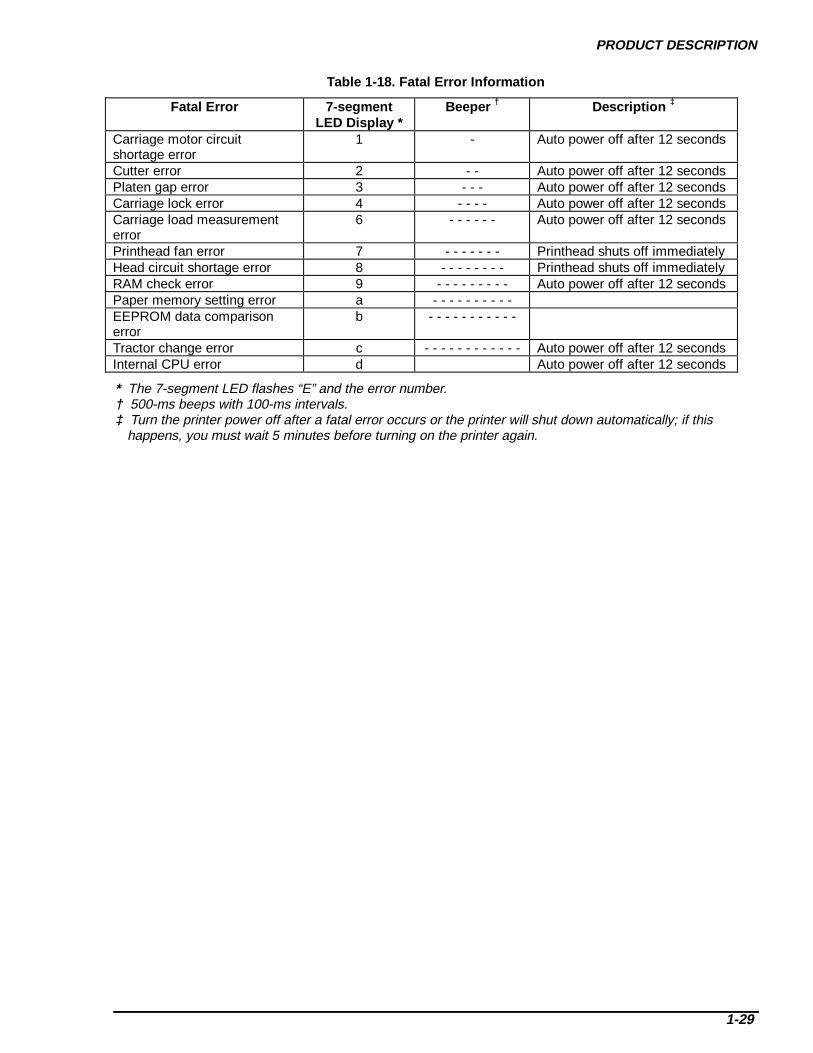
Table 1-18. Fatal Error Information
Fatal Error 7-segmentLED Display *
Beeper † Descript ion ‡
Carriage motor circuitshortage error
1 - Auto power off after 12 seconds
Cutter error 2 - - Auto power off after 12 secondsPlaten gap error 3 - - - Auto power off after 12 secondsCarriage lock error 4 - - - - Auto power off after 12 secondsCarriage load measurementerror
6 - - - - - - Auto power off after 12 seconds
Printhead fan error 7 - - - - - - - Printhead shuts off immediatelyHead circuit shortage error 8 - - - - - - - - Printhead shuts off immediatelyRAM check error 9 - - - - - - - - - Auto power off after 12 secondsPaper memory setting error a - - - - - - - - - -EEPROM data comparisonerror
b - - - - - - - - - - -
Tractor change error c - - - - - - - - - - - - Auto power off after 12 secondsInternal CPU error d Auto power off after 12 seconds
* The 7-segment LED flashes “E” and the error number.† 500-ms beeps with 100-ms intervals.‡ Turn the printer power off after a fatal error occurs or the printer will shut down automatically; if this
happens, you must wait 5 minutes before turning on the printer again.

DFX-8500
1-30
DIP SWITCH SETTINGSThere are 5 banks of 8 DIP switches located at the front paper entrance of the printer. The printer defaultsettings are set using these DIP switches. When the printer is turned on or reset, the DIP switch selectionsare treated as the default setup. If the setup is changed, the printer should be reset or turned off and on.Table 1-19 shows the DIP switch selections for this printer.
Table 1-19. DIP Switch Settings
Switch No. Function Off On Factory Setting1-1 to 1-6 Character table See Tables 1-18 or 1-19. All Off1-7 Skip over perforation Inactive Active Off1-8 Print direction Bi-d. Uni-d. Off2-1 to 2-4 Page length for front tractor See Table 1-20. All Off2-5 to 2-8 Page length for rear tractor See Table 1-21. All Off3-1 Auto tear-off Inactive Active Off3-2 Zero slash Inactive Active Off3-3 Auto line feed Inactive Active Off3-4 Buzzer Active Inactive Off3-5 Auto carriage return
(IBM 2381 Plus)Inactive Active Off
3-6 IBM character table Table 2 Table 1 Off3-7 Auto cut mode Inactive Active Off3-8 Software ESC/P IBM 2381 Plus Off4-1 Input buffer Active Inactive Off4-2 Auto I/F wait time 10 sec. 30 sec. Off4-3 to 4-4 I/F mode See Table 1-22. All Off4-5 to 4-6 Serial I/F parity See Table 1-23. All Off4-7 to 4-8 Serial I/F baud rate See Table 1-24. All Off5-1 Overlapping multi-sheet forms Inactive Active Off5-2 Continuous forms with labels Inactive Active Off5-3 Skip over binding Inactive Active Off5-4 Paper memory Memory a Memory b Off5-5 to 5-8 (reserved) - - Off

PRODUCT DESCRIPTION
1-31
Table 1-20. Character Table Sett ing (Standard)
SW1-1 SW1-2 SW1-3 SW1-4 SW1-5 SW1-6 Character tableOff Off Off Off Off Off PC437 (US, standard Europe)Off Off Off Off Off On PC850 (Multilingual)Off Off Off Off On Off PC860 (Portuguese)Off Off Off Off On On PC861 (Icelandic)Off Off Off On Off Off PC863 (Canadian-French)Off Off Off On Off On PC865 (Nordic)Off Off Off On On Off AbicompOff Off Off On On On BRASCIIOff Off On Off Off Off Roman 8Off Off On Off Off On ISO Latin 1Off Off On Off On Off Italic USAOff Off On Off On On Italic FranceOff Off On On Off Off Italic GermanOff Off On On Off On Italic U.KOff Off On On On Off Italic DenmarkOff Off On On On On Italic SwedenOff On Off Off Off Off Italic ItalyOff On Off Off Off On Italic Spain
Others PC437
DFX-8500
1-32
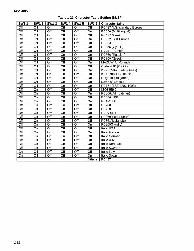
Table 1-21. Character Table Sett ing (NLSP)
SW1-1 SW1-2 SW1-3 SW1-4 SW1-5 SW1-6 Character tableOff Off Off Off Off Off PC437 (US, standard Europe)Off Off Off Off Off On PC850 (Multilingual)Off Off Off Off On Off PC437 GreekOff Off Off Off On On PC852 East EuropeOff Off Off On Off Off PC853Off Off Off On Off On PC855 (Cyrillic)Off Off Off On On Off PC857 (Turkish)Off Off Off On On On PC866 (Russian)Off Off On Off Off Off PC869 (Greek)Off Off On Off Off On MAZOWIA (Poland)Off Off On Off On Off Code MJK (CSFR)Off Off On Off On On ISO 8859-7 (Latin/Greek)Off Off On On Off Off ISO Latin 1T (Turkish)Off Off On On Off On Bulgaria (Bulgarian)Off Off On On On Off Estonia (Estonia)Off Off On On On On PC774 (LST 1283:1993)Off On Off Off Off Off ISO8859-2Off On Off Off Off On PC866LAT (Latvian)Off On Off Off On Off PC866 UKROff On Off Off On On PCAPTECOff On Off On Off Off PC708Off On Off On Off On PC720Off On Off On On Off PC AR864Off On Off On On On PC860(Portuguese)Off On On Off Off Off PC861(Icelandic)Off On On Off Off On PC865(Nordic)Off On On Off On Off Italic USAOff On On Off On On Italic FranceOff On On On Off Off Italic GermanOff On On On Off On Italic U.KOff On On On On Off Italic DenmarkOff On On On On On Italic SwedenOn Off Off Off Off Off Italic ItalyOn Off Off Off Off On Italic Spain
Others PC437

PRODUCT DESCRIPTION
1-33
Table 1-22. Front Tractor Page Length
SW2-1 SW2-2 SW2-3 SW2-4 Page length for front tractorOff Off Off Off 11 inchesOff Off Off On 3 inchesOff Off On Off 3.5 inchesOff Off On On 4 inchesOff On Off Off 5.5 inchesOff On Off On 6 inchesOff On On Off 7 inchesOff On On On 8 inchesOn Off Off Off 8.5 inchesOn Off Off On 70/6 inchesOn Off On Off 12 inchesOn Off On On 14 inchesOn On Off Off 17 inchesOn On Off On Others
Others 11 inches
Table 1-23. Rear Tractor Page Length
SW2-1 SW2-2 SW2-3 SW2-4 Page length for rear tractorOff Off Off Off 11 inchesOff Off Off On 3 inchesOff Off On Off 3.5 inchesOff Off On On 4 inchesOff On Off Off 5.5 inchesOff On Off On 6 inchesOff On On Off 7 inchesOff On On On 8 inchesOn Off Off Off 8.5 inchesOn Off Off On 70/6 inchesOn Off On Off 12 inchesOn Off On On 14 inchesOn On Off Off 17 inchesOn On Off On Others
Others 11 inches
Table 1-24. I/F Selection
SW4-3 SW4-4 I/F ModeOff Off AutoOff On Parallel I/FOn Off Serial I/FOn On Optional I/F
Table 1-25. Serial I/F Parity Setting
SW4-5 SW4-6 Serial parityOff Off NoneOff On OddOn Off EvenOn On Ignore
DFX-8500
1-34
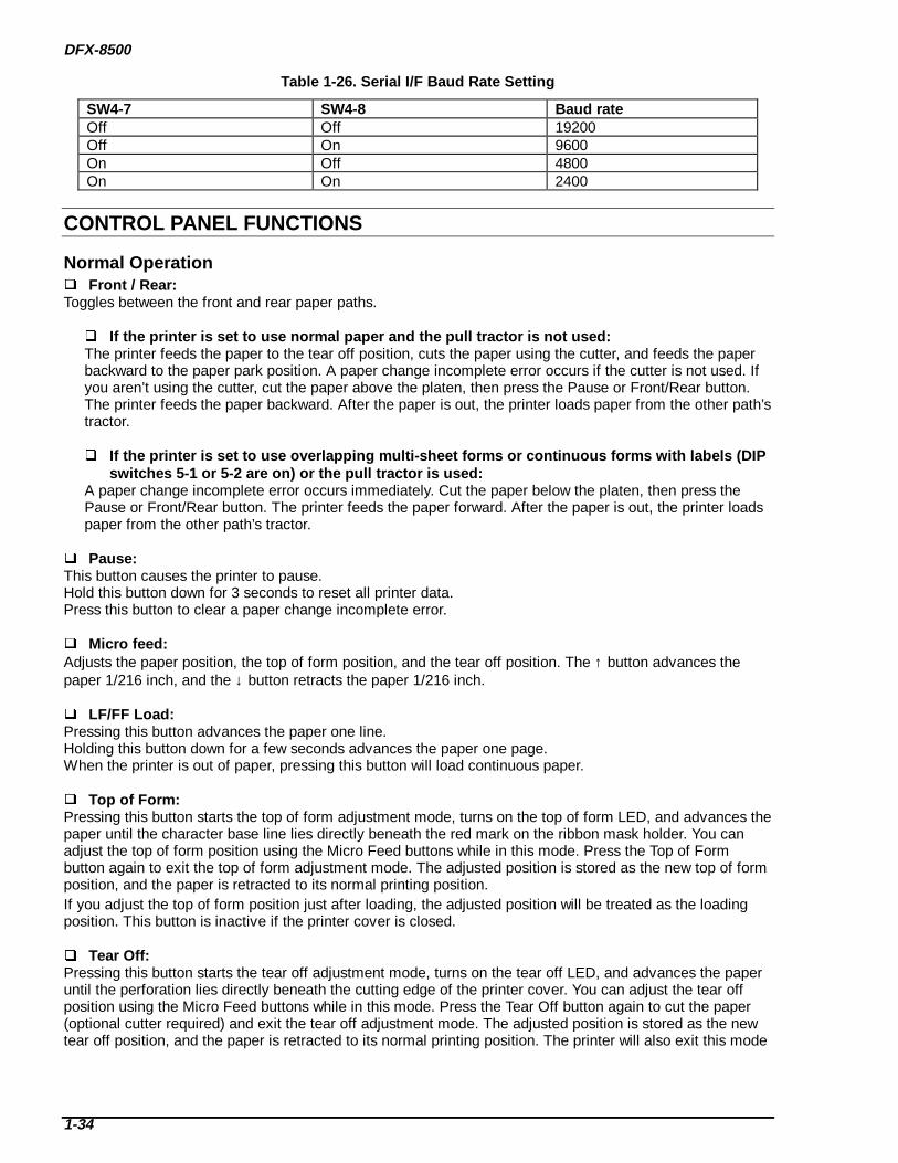
Table 1-26. Serial I/F Baud Rate Setting
SW4-7 SW4-8 Baud rateOff Off 19200Off On 9600On Off 4800On On 2400
CONTROL PANEL FUNCTIONS
Normal Operation Front / Rear:Toggles between the front and rear paper paths.
If the printer is set to use normal paper and the pull t ractor is not used:The printer feeds the paper to the tear off position, cuts the paper using the cutter, and feeds the paperbackward to the paper park position. A paper change incomplete error occurs if the cutter is not used. Ifyou aren’t using the cutter, cut the paper above the platen, then press the Pause or Front/Rear button.The printer feeds the paper backward. After the paper is out, the printer loads paper from the other path’stractor.
If the printer is set to use overla pping multi-sheet fo rms or cont inuous fo rms with labels (DIPswitches 5-1 or 5-2 are on) or the pull t ractor is used:
A paper change incomplete error occurs immediately. Cut the paper below the platen, then press thePause or Front/Rear button. The printer feeds the paper forward. After the paper is out, the printer loadspaper from the other path’s tractor.
Pause:This button causes the printer to pause.Hold this button down for 3 seconds to reset all printer data.Press this button to clear a paper change incomplete error.
Micro feed:Adjusts the paper position, the top of form position, and the tear off position. The ↑ button advances thepaper 1/216 inch, and the ↓ button retracts the paper 1/216 inch.
LF/FF Load:Pressing this button advances the paper one line.Holding this button down for a few seconds advances the paper one page.When the printer is out of paper, pressing this button will load continuous paper.
Top of Form:Pressing this button starts the top of form adjustment mode, turns on the top of form LED, and advances thepaper until the character base line lies directly beneath the red mark on the ribbon mask holder. You canadjust the top of form position using the Micro Feed buttons while in this mode. Press the Top of Formbutton again to exit the top of form adjustment mode. The adjusted position is stored as the new top of formposition, and the paper is retracted to its normal printing position.If you adjust the top of form position just after loading, the adjusted position will be treated as the loadingposition. This button is inactive if the printer cover is closed.
Tear Off:Pressing this button starts the tear off adjustment mode, turns on the tear off LED, and advances the paperuntil the perforation lies directly beneath the cutting edge of the printer cover. You can adjust the tear offposition using the Micro Feed buttons while in this mode. Press the Tear Off button again to cut the paper(optional cutter required) and exit the tear off adjustment mode. The adjusted position is stored as the newtear off position, and the paper is retracted to its normal printing position. The printer will also exit this mode
PRODUCT DESCRIPTION
1-35
if it receives data from the host computer.
Copy:This button toggles the printer between copy mode or normal mode.
Pitch:Press this button to select among the following pitches:
10 cpi, 12 cpi, 15 cpi, 17 cpi, 20 cpi and PS (proportional spacing)
Font:Press this button to select among the following fonts:
Super Draft, Draft, Roman, Sans Serif
Paper Select:Paper sizes can be preset. Pressing this button selects one of the following preset paper sizes:
1, 2, 3, 4, 5, 6, 7, and 8: Paper sizes must be created within the printer driver. See the User’s Guide for details.
0: Default; use when no driver settings have been made.a, b: Hardware settings used for sheets with labels. See the User’s Guide for
details.
If the printer is set to use normal paper and the pull t ractor is not used:Pressing this button retracts the paper to the paper park position. If a print job was just performed, theprinter will advance the paper to the tear off position and cut the paper (if the optional cutter is installed).If the cutter is not installed, a paper change incomplete error occurs. Manually cut the paper above theplaten, then press the Pause button. The printer will retract the paper. After the new paper has beenplaced into position, the printer will load the new paper. If a paper change incomplete error occurred,insert the new paper and press the Pause button to load it.
If the printer is set to use overla pping multi-sheet fo rms or cont inuous fo rms with labels (DIPswitches 5-1 or 5-2 are on) or the pull t ractor is used:
Pressing this button will cause an immediate paper change incomplete error. Manually cut the paperbelow the platen, then push the Pause button. The printer will advance the paper until it is out, then loadthe selected paper. If you get another paper change incomplete error, insert the new paper and press thePause button to load it.
If the paper setting is cu rrently sett ing a or b:The printer advances the paper. If a paper path change incomplete error occurs, cut the paper belowthe platen and press the Pause button. The printer ejects the paper.
If the printer is not currently us ing the a and b settings:The printer advances the paper to the tear-off position and cuts the paper if the cutter is installed.The printer then retracts the paper to the paper park position. If the cutter is not installed, or theprinter fails to advance the paper to the paper park position, a paper path change incomplete errorwill occur. If this happens, cut the paper above the platen, then press the Pause button. The printerretracts the paper.

DFX-8500
1-36
Advanced Control Panel Functions
See Table 1-16 on page 1-26 for instructions on how to access these functions.
Self test:Prints the self test pattern. To cancel the self test, press the Pause button and turn off the printer.
DIP switch setting print:Prints the settings of all DIP switches.
Hex dump:Starts a hex dump; all input data is printed as a list of hexadecimal numbers beside the correspondingcharacters.
Clear EEPROM Area 1:Resets all user settings.
Clear EEPROM Area 2:Resets the printer mechanism adjustment data to the standard factory setting.
Clear r ibbon counter:Resets the ribbon counter.
Paper memory sett ing:Accesses settings that improve printing on label sheets and overlapping forms.
Mechanism adjustment:Starts mechanism adjustment mode. You can adjust the beta value, flight time value, and Bi-D setting usingthis mode.
Platen gap adjustment:Starts platen gap parameter adjustment mode. You can adjust the alpha and beta values using this mode.
Set printable area:Starts automatic measurement seeking. The carriage deceleration time is measured and saved in theEEPROM.

PRODUCT DESCRIPTION
1-37
Automatic Detection Functions Cover open detect ion:When the cover is opened, the printer stops printing and pauses after several beeps. The printer stayspaused until the cover is closed and the Pause button is pressed.
Paper width detection:The printer detects the right paper edge and determines the right edge of the printable area. Print jobs thatextend beyond that edge won't be printed.
Automatic platen gap adjustment:This printer measures the thickness of each new paper stack. The distance between the printhead and theplaten is then automatically adjusted.
Skip over binding:If the paper is a multi-sheet form with thick bindings that could scratch the printhead during paper feeding,this feature allows the printhead to lift up and over these bindings to avoid paper jams. This feature can beactivated using DIP switches. (See “Dip Switch Settings” on page 1-30.) Use of this feature will reduce printspeed.
Auto cut mode:The printer automatically cuts the paper at each perforation during printing. This function is valid when theperforation cutter is used, DIP switch 3-7 is on, and the paper is over 4 inches long. The printer driversetting has priority over the DIP switch setting. Do not use this mode for labels, continuous forms withlabels, or overlapping multi-sheet forms.
Automatic Top of Form (TOF) position adjustment:When the TOF position is different from the loading position, the printer automatically feeds the paper to thenext TOF position.
DFX-8500
1-38
PAPER MEMORY FUNCTIONSUse the paper memory function to get better quality printouts on overlapping multi-sheet forms orcontinuous forms with labels. Before using paper memory, you must use the control panel and DIP switchesto set the paper length. This function is available only when using the front paper path.
How to recall paper memories:Paper settings stored in memory can be used by setting the appropriate DIP switches.
Notes: A 1-inch perforation area is automatically included for overlapping multi-sheet forms. The commands ESC C, ESC (C, and ESC (c can be used with stored paper settings. The ESC N command can be used with stored paper settings, but if the perforation length is set to
less than 1 inch, the setting is ignored when using overlapping multi-sheet forms. ESC 0 cannot be used with stored paper settings for overlapping multi-sheet forms. You must adjust the loading position for overlapping multi-sheet forms each time they are used. If the paper is not at the top of form position when the printer is turned on, the printer automatically
advances the paper to the top of the next page.
How to save sett ings for all paper except cont inuous fo rms with labels (sett ings a & b only):1) Make sure the printer is turned off.2) Select a memory location. (See “DIP Switch Settings” on page 1-30.)3) Select the page length. (See “DIP Switch Settings” on page 1-30.)4) Select the paper type. (See “DIP Switch Settings” on page 1-30.)5) Turn the printer on while pressing the Paper Select button.6) The printer writes the information in the memory you selected, and beeps. How to save sett ings for continuous fo rms with labels (sett ings a & b only):1) Make sure the printer is turned off.2) Select a memory location. (See “DIP Switch Settings” on page 1-30.)3) Select the page length. (See “DIP Switch Settings” on page 1-30.)4) Select the paper type. (See “DIP Switch Settings” on page 1-30.)5) Turn the printer on while pressing the Paper Select button.6) Set the label size. a) Open the printer cover. b) Move the pointer (see Figure 1-23) to the label’s upper left corner: To move the carriage up or down, use the Micro Feed buttons To move the carriage right or left, slide the printhead manually. c) Press the Top of Form button. d) Move the pointer to the lower right corner of the label. e) Press the Top of Form button. f) Close the printer cover.7) Listen for confirmation. 1 or 2 beeps: The settings were saved correctly. 3 beeps: the settings were not saved correctly. Try again.

PRODUCT DESCRIPTION
1-39
INITIALIZATIONS
Hardware InitializationInitialization occurs when the printer is turned on or when the printer receives an /INIT signal (negativepulse) or cold-reset command (remote RS command). Initialization does the following:
initializes the printer mechanism clears all data buffers cancels downloaded character translation places the printer in a stand-by state performs a software initialization (see below)
Software InitializationThe control codes ESC @ (for ESC/P) or ESC [K (for IBM/Lexmark 2381 Plus) will also initialize the printer.Software initialization sets all printer settings to their default values.
Panel InitializationYou can initialize the printer from the control panel by pressing the Reset button for 3 seconds. Thisinitialization:
clears all data in the buffer performs a software initialization

DFX-8500
1-40
1.5 MAIN COMPONENTSThe main components of the DFX-8500 are:
Printer mechanism: M-3I60 Main control board: C204 Main board Mechanism driver board: C204 DRV board Printhead driver board: C204 DRV-B board DIP switch board: C204 SUB board Power supply board: C204 PSB/PSE board Control Panel Housing
C204 Main Board, C204 DRV Board,C204 DRV-B Board, and C204 SUB Board
C204 PSB/PSE Board
Panel UnitPrinthead Junction Board(PPL Name: Intermit Board)
Carriage Connector Junction Board(PPL Name: CR Intermit Board)
Connector Junction Board
Figure 1-23. Main Components
PRODUCT DESCRIPTION
1-41
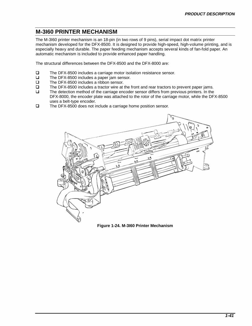
M-3I60 PRINTER MECHANISMThe M-3I60 printer mechanism is an 18-pin (in two rows of 9 pins), serial impact dot matrix printermechanism developed for the DFX-8500. It is designed to provide high-speed, high-volume printing, and isespecially heavy and durable. The paper feeding mechanism accepts several kinds of fan-fold paper. Anautomatic mechanism is included to provide enhanced paper handling.
The structural differences between the DFX-8500 and the DFX-8000 are:
The DFX-8500 includes a carriage motor isolation resistance sensor. The DFX-8500 includes a paper jam sensor. The DFX-8500 includes a ribbon sensor. The DFX-8500 includes a tractor wire at the front and rear tractors to prevent paper jams. The detection method of the carriage encoder sensor differs from previous printers. In the
DFX-8000, the encoder plate was attached to the rotor of the carriage motor, while the DFX-8500 uses a belt-type encoder.
The DFX-8500 does not include a carriage home position sensor.
Figure 1-24. M-3I60 Printer Mechanism
DFX-8500
1-42
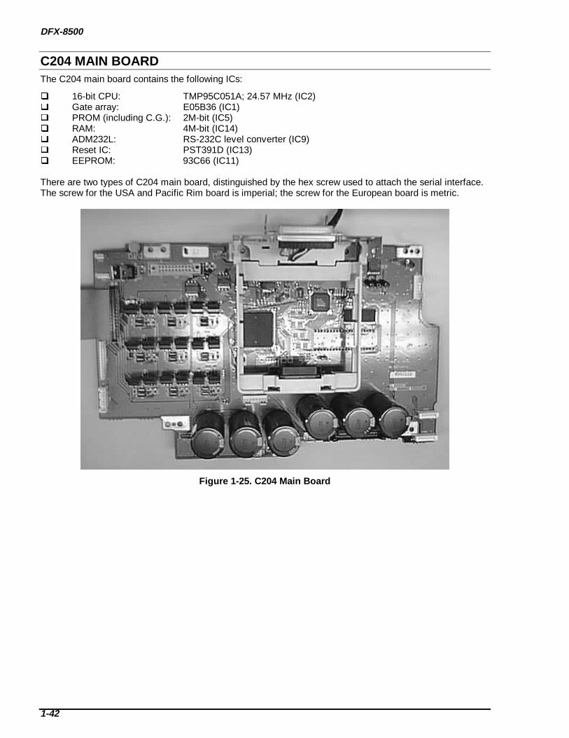
C204 MAIN BOARDThe C204 main board contains the following ICs:
16-bit CPU: TMP95C051A; 24.57 MHz (IC2) Gate array: E05B36 (IC1) PROM (including C.G.): 2M-bit (IC5) RAM: 4M-bit (IC14) ADM232L: RS-232C level converter (IC9) Reset IC: PST391D (IC13) EEPROM: 93C66 (IC11)
There are two types of C204 main board, distinguished by the hex screw used to attach the serial interface.The screw for the USA and Pacific Rim board is imperial; the screw for the European board is metric.
Figure 1-25. C204 Main Board
PRODUCT DESCRIPTION
1-43
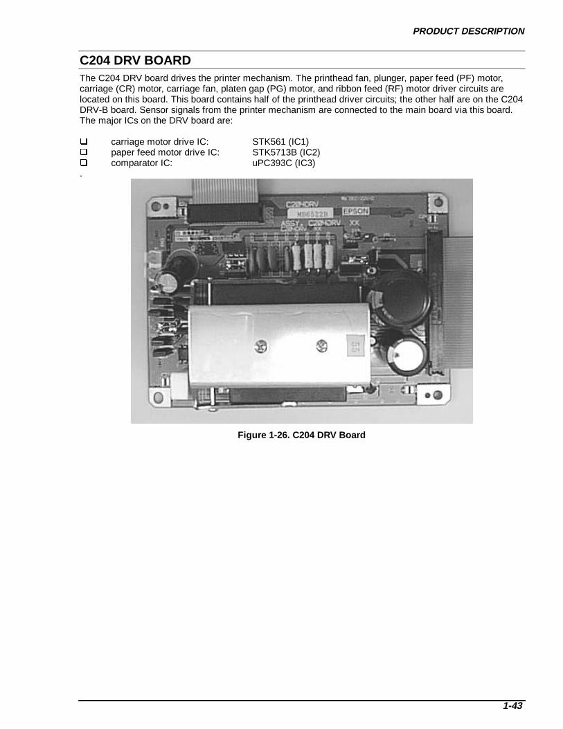
C204 DRV BOARDThe C204 DRV board drives the printer mechanism. The printhead fan, plunger, paper feed (PF) motor,carriage (CR) motor, carriage fan, platen gap (PG) motor, and ribbon feed (RF) motor driver circuits arelocated on this board. This board contains half of the printhead driver circuits; the other half are on the C204DRV-B board. Sensor signals from the printer mechanism are connected to the main board via this board.The major ICs on the DRV board are:
carriage motor drive IC: STK561 (IC1) paper feed motor drive IC: STK5713B (IC2) comparator IC: uPC393C (IC3).
Figure 1-26. C204 DRV Board
DFX-8500
1-44
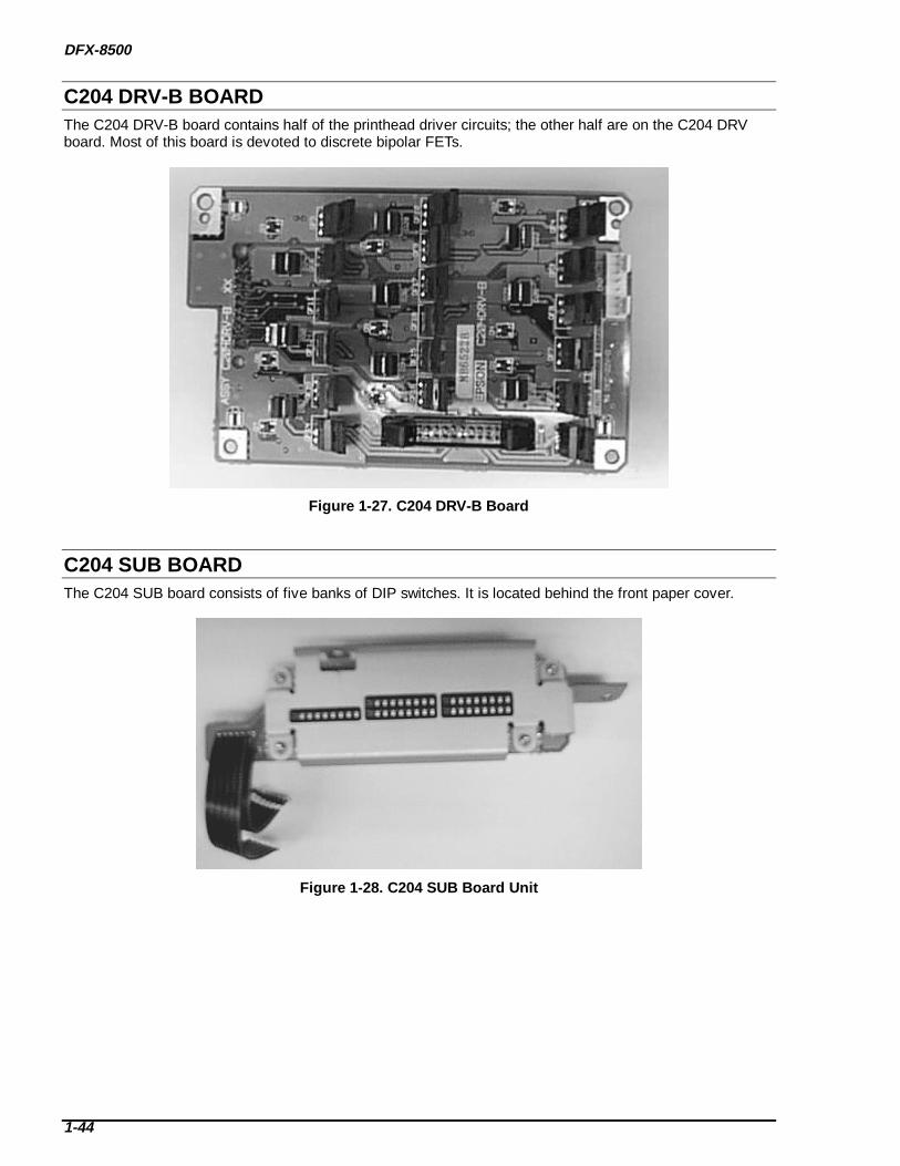
C204 DRV-B BOARDThe C204 DRV-B board contains half of the printhead driver circuits; the other half are on the C204 DRVboard. Most of this board is devoted to discrete bipolar FETs.
Figure 1-27. C204 DRV-B Board
C204 SUB BOARDThe C204 SUB board consists of five banks of DIP switches. It is located behind the front paper cover.
Figure 1-28. C204 SUB Board Unit

PRODUCT DESCRIPTION
1-45
C204 PSB/PSE BOARDThe C204 PSB/PSE board is a power supply circuit board that generates power for the main and driverboards. There is a cooling fan on the top of this board. The PSB board takes 100-120 VAC, and the PSEboard takes 220-240 VAC.
Figure 1-29. C204 PSB/PSE Board

DFX-8500
1-46
CONTROL PANELThe control panel for this printer consists of buttons, LEDs, and beepers (See Figure 1-22 on page 1-25.).
HOUSINGThe housing for this printer consists of the upper housing, lower housing, printer cover, ink cartridge cover,rear sheet guide, tractor unit, knob, adjust lever and release lever.
The DFX-8500 housing has many more components than previous DFX housings. The lower case holds themechanism and circuits, covered by the upper case, bottom plate and side cover. The housing has largeopenings in both the front and rear for paper entry and exit. It also has a lid on the bottom plate to enablethe PROM on the main board to be easily replaced.
Figure 1-30. Housing

CHAPTER 2OPERATING PRINCIPLES
2.1 PRINTER MECHANISM OPERATION__________________________________________ 2-1Printhead Mechanism ______________________________________________________________________ 2-4Carriage Mechanism_______________________________________________________________________ 2-5Platen Gap Adjustment Mechanism ___________________________________________________________ 2-6Paper Feed Mechanism_____________________________________________________________________ 2-7
Tractor Wire Operation___________________________________________________________________ 2-9Ribbon Feed and Tractor Select Mechanisms___________________________________________________ 2-10Plunger Mechanism ______________________________________________________________________ 2-12
2.2 POWER SUPPLY OPERATION _______________________________________________ 2-13Power Supply Overview ___________________________________________________________________ 2-14
2.3 CONTROL CIRCUITS _______________________________________________________ 2-17Control Circuit Operation Overview _________________________________________________________ 2-17Reset Circuit ____________________________________________________________________________ 2-21Sensor Circuits __________________________________________________________________________ 2-22Carriage Motor Drive Circuit _______________________________________________________________ 2-26Paper Feed Motor Drive Circuit _____________________________________________________________ 2-32Ribbon Feed Motor Drive Circuit____________________________________________________________ 2-34Platen Gap Motor Drive Circuit _____________________________________________________________ 2-35Plunger Drive Circuit _____________________________________________________________________ 2-37Printhead Drive Circuit____________________________________________________________________ 2-38

OPERATING PRINCIPLES
2-1
2.1 PRINTER MECHANISM OPERATIONThis section describes the Model 3I60 printer mechanism and explains how the printer works. The printermechanism features an 18-pin, impact dot printhead for serial printing. The printer mechanism is the maincomponent of the printer and is supported by the power supply and control circuits. Figure 2-1 shows theprinter mechanism.
The printer mechanism consists of the following main components:
Printhead:
The printhead is the component that actually prints characters (dot matrix patterns). The pins are arrangedin 2 vertical lines. To print, the pins strike against the ribbon and the paper surface. As the printhead moveshorizontally, this operation is repeated to print an entire character. The printhead includes a fan andthermistor. When the printhead or fan is too hot, the printer stops printing until it cools. (See “PrintheadDrive Circuit” on page 2-38.)
Plunger mechanism:
During printing, the paper bail holds the paper under tension so that it is fed smoothly. When paper is loadedor ejected or when the tear off button is pressed, the paper bail needs to move up to prevent a paper jam.The bail is spring-loaded and held down by the plunger. When current is withheld from the plunger, thepaper bail is lifted by the spring.
Paper Bail
Printhead
Front Tractor
Ribbon Feed Motor
Platen Gap Motor
ConnectorJunctionBoard
Paper Feed Timing Belt
Plunger
Figure 2-1. Model 3I60 Printer Mechanism

DFX-8500
2-2
Carriage mechanism:
The carriage mechanism moves the printhead along the platen. The carriage motor drives the carriage. Theprinthead is attached to the carriage. The carriage encoder sensor detects the carriage motor speed andcarriage position. The carriage motor is closed-loop controlled. Because the carriage motor is driven at avery high speed, it has an isolation resistance sensor to detect abnormal resistance. The sensor detects anerror if the resistance is less than 2.2 kΩ. (See “Carriage Motor Drive Circuit” on page 2-26.)
Interlock switch:
When the top cover is opened, the interlock switch cuts the drive voltage to the carriage motor to slow downthe carriage speed and prevent accidents. This is necessary because the carriage ordinarily moves atdangerous speed. A control circuit decelerates the carriage motor. (See “Carriage Motor Drive Circuit” onpage 2-26.) Printing resumes when the top cover is closed.
Auto platen gap adjustment mechanism:
The printer mechanism has an automatic platen gap adjustment function that measures paper thickness andadjusts the gap between the platen and printhead accordingly. The printer mechanism adjusts the platen gapby moving the carriage (and printhead) either forward or backward. The front and rear carriage guide shaftsthat hold the carriage are eccentrically mounted; the carriage moves as the platen gap motor rotates theshafts. The platen gap sensor transmits the amount of movement to the control circuit.
Ribbon feed mechanism:
The printer's ribbon cartridge contains an endless ribbon. The ribbon feed mechanism moves the ribbon sothat there is always fresh ribbon in front of the pins. The ribbon feed motor drives the ribbon feedmechanism.
Platen Gap Motor
Rear Carriage Guide Shaft
Printhead
Interlock SwitchCarriageMotor
Carriage Encoder Belt
Carriage Sensor
Carriage Timing Belt
Platen Gap Home Position Sensor
Ribbon FeedMotor
Figure 2-2. Printer Mechanism Op erat ion (1)

OPERATING PRINCIPLES
2-3
Paper feed mechanism:
The paper feed motor drives the paper feed mechanism, which controls both line and form feeding.
The front, rear, and top paper end sensors detect paper in the paper path, and stop printing when there is nopaper. The printer is equipped with three paper end sensors: the front paper end sensor at the front tractor,the rear paper end sensor at the rear tractor, and the top paper end sensor at the paper bail. The pull tractorsensor detects whether the optional pull tractor unit is installed.
The printer is also equipped with a paper jam sensor. The control circuit reads the signals from the sensorsand indicates when an error occurs.
Tractor select mechanism:
The printer mechanism has two paper entrances: one at the front tractor and one at the rear tractor. Bycontrolling the ribbon feed motor, the tractor select mechanism chooses which tractor to use, and powerfrom the paper feed motor is conveyed to that tractor via a series of gears. The tractor select sensor detectsthe selected tractor and signals that information to the control circuit. (See “Ribbon Feed and Tractor SelectMechanisms” on page 2-10.)
Paper Bail
Printhead
Front Paper End Sensor
Front Tractor Sprocket
Ribbon Feed Motor
Paper Feed Motor
Rear Tractor Sprocket
Rear Paper End SensorTractor Select Sensor
Paper Jam Sensor
Top Paper End Sensor
Pull Tractor Sensor
Plunger
Pull TractorPaper
Figure 2-3. Printer Mechanism Op erat ion (2)

DFX-8500
2-4
PRINTHEAD MECHANISMThe printhead is a charge-type, impact dot printhead. Figure 2-4 contains a diagram of printhead operation.The dot wire is attached to the actuating spring at point A. The actuating spring is pulled back (left in thefigure) by magnetic force when the printer is on and not printing. When current flows through the coil, acounter-magnetic field is induced in the coil. Then, the actuating spring ejects the dot wire forward againstthe ink ribbon, printing a dot on the paper.
Actuating Spring
Mask Holder Platen
Ribbon
Dot Wire
Printhead Drive Coil
Iron Core
GND
+35 VDC
Figure 2-4. Printhead
OPERATING PRINCIPLES
2-5
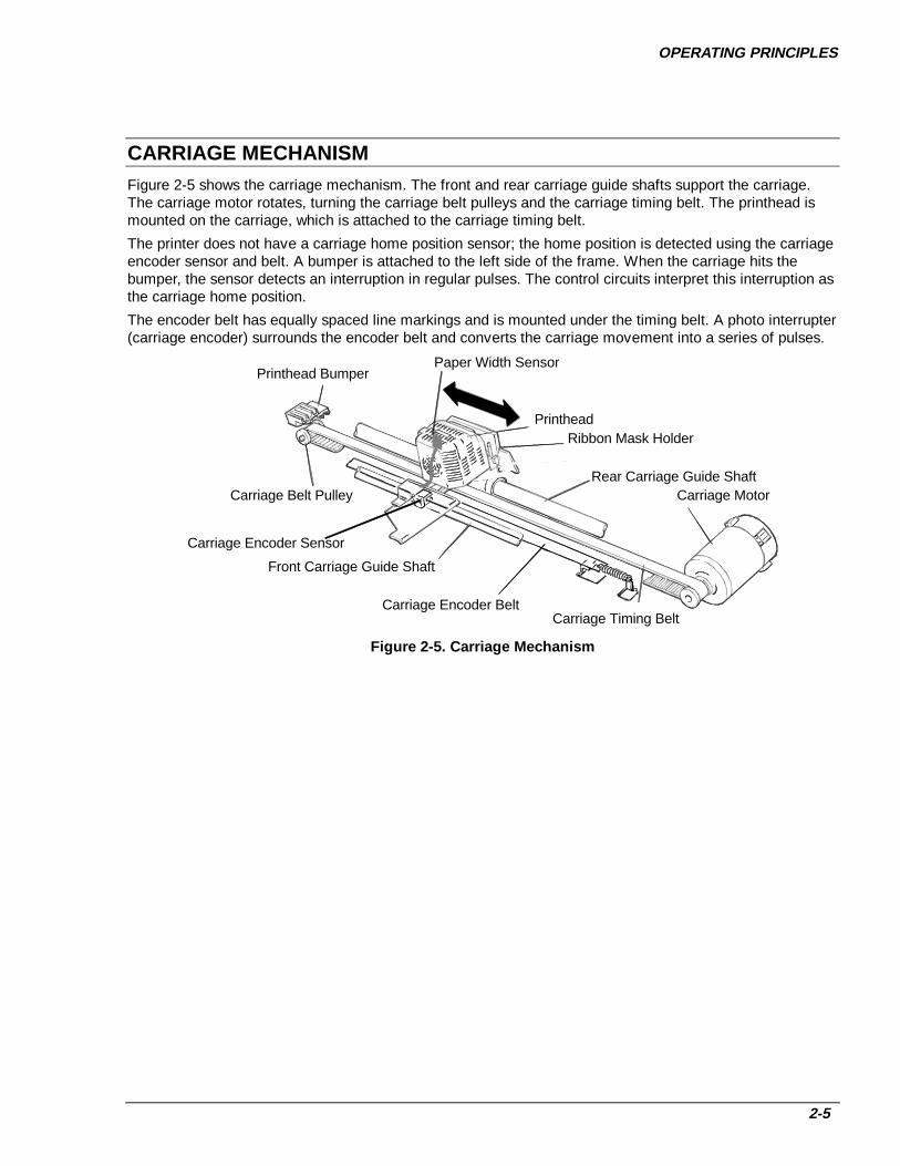
CARRIAGE MECHANISMFigure 2-5 shows the carriage mechanism. The front and rear carriage guide shafts support the carriage.The carriage motor rotates, turning the carriage belt pulleys and the carriage timing belt. The printhead ismounted on the carriage, which is attached to the carriage timing belt.
The printer does not have a carriage home position sensor; the home position is detected using the carriageencoder sensor and belt. A bumper is attached to the left side of the frame. When the carriage hits thebumper, the sensor detects an interruption in regular pulses. The control circuits interpret this interruption asthe carriage home position.
The encoder belt has equally spaced line markings and is mounted under the timing belt. A photo interrupter(carriage encoder) surrounds the encoder belt and converts the carriage movement into a series of pulses.
Carriage Timing BeltCarriage Encoder Belt
Front Carriage Guide Shaft
Carriage Belt Pulley
Printhead Bumper
PrintheadRibbon Mask Holder
Rear Carriage Guide ShaftCarriage Motor
Carriage Encoder Sensor
Paper Width Sensor
Figure 2-5. Carriage Mechanism

DFX-8500
2-6
PLATEN GAP ADJUSTMENT MECHANISMFigure 2-6 shows the platen gap adjustment mechanism. The front and rear carriage guide shafts supportingthe carriage are eccentrically mounted. The rotation of the platen gap motor is transmitted to the rearcarriage guide shaft through the gear train. Counterclockwise rotation of the motor expands the platen gap,and clockwise rotation reduces it.
The encoder plate has equally spaced slits and turns on the motor axis. When the motor rotates, the platengap sensor detects these slits and sends out pulses. Each pulse corresponds to a platen gap change of0.0025 mm. The platen gap can range from 0.35 to 0.84 mm.
Platen
Ribbon Mask Holder
Platen Roller Gear
Platen Gap Motor
Platen Gap Encoder Plate
Platen Gap Sensor
Platen Roller Transmission Gear
Rear Carriage Guide Shaft
Printhead
CWCCW
Figure 2-6. Platen Gap Adjustment Mechanism
OPERATING PRINCIPLES
2-7
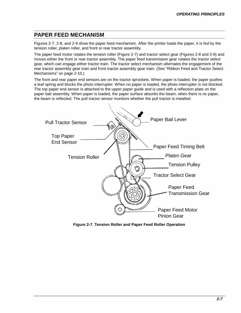
PAPER FEED MECHANISMFigures 2-7, 2-8, and 2-9 show the paper feed mechanism. After the printer loads the paper, it is fed by thetension roller, platen roller, and front or rear tractor assembly.
The paper feed motor rotates the tension roller (Figure 2-7) and tractor select gear (Figures 2-8 and 2-9) andmoves either the front or rear tractor assembly. The paper feed transmission gear rotates the tractor selectgear, which can engage either tractor train. The tractor select mechanism alternates the engagement of therear tractor assembly gear train and front tractor assembly gear train. (See “Ribbon Feed and Tractor SelectMechanisms” on page 2-10.)
The front and rear paper end sensors are on the tractor sprockets. When paper is loaded, the paper pushesa leaf spring and blocks the photo interrupter. When no paper is loaded, the photo interrupter is not blocked.The top paper end sensor is attached to the upper paper guide and is used with a reflection plate on thepaper bail assembly. When paper is loaded, the paper surface absorbs the beam; when there is no paper,the beam is reflected. The pull tractor sensor monitors whether the pull tractor is installed.
Paper Bail Lever
Paper Feed Timing Belt
Tractor Select Gear
Paper Feed MotorPinion Gear
Pull Tractor Sensor
Top Paper End Sensor
Tension Roller Platen Gear
Tension Pulley
Paper FeedTransmission Gear
Figure 2-7. Tension Roller and Paper Feed Roller Op eration

DFX-8500
2-8
Paper
Tension RollerPaper Bail
Front Paper End Sensor
Front TractorPaper Feed Motor Pinion Gear
Tractor Select Gear
Paper Feed Transmission Gear
Figure 2-8. Front T ractor Assembly Operation
Paper
Tension Roller
Paper Bail
Tractor Select Gear
Paper FeedMotor Pinion
Rear Tractor
Rear Paper End Sensor
Paper FeedTransmission Gear
Figure 2-9. Rear Tractor Assembly Operation

OPERATING PRINCIPLES
2-9
Tractor Wire OperationThe printer is equipped with a tractor wire to straighten and maintain the proper horizontal tension in thepaper and prevent paper jams. The tractor wire tension spring on the right frame pulls the wire. Figure 2-10shows how the tractor wire operates.
The front left tractor sprocket or rear right tractor sprocket is held in place on the tractor shaft by a smallclamp, while the other sprocket (the front right sprocket or rear left sprocket) can move freely along thetractor shafts. When the tractor release lever is released, the sprocket can move smoothly along the tractorshafts. When the tractor release lever is engaged, the sprocket can still move along the tractor shafts, butthe tractor wire applies some tension.
In Figure 2-10, range A shows the movement range of the left tractor sprocket when the tractor release leveris released. Range B shows the movement range of the right tractor sprocket.
If the paper in the printer begins to rise up or doesn’t lie flat, you can pull the tractor wire to the right tostabilize the paper tension between the left and right tractor sprockets.
Tractor WireTractor Wire Tension Spring
Tension
Figure 2-10. T ractor Wire Operation
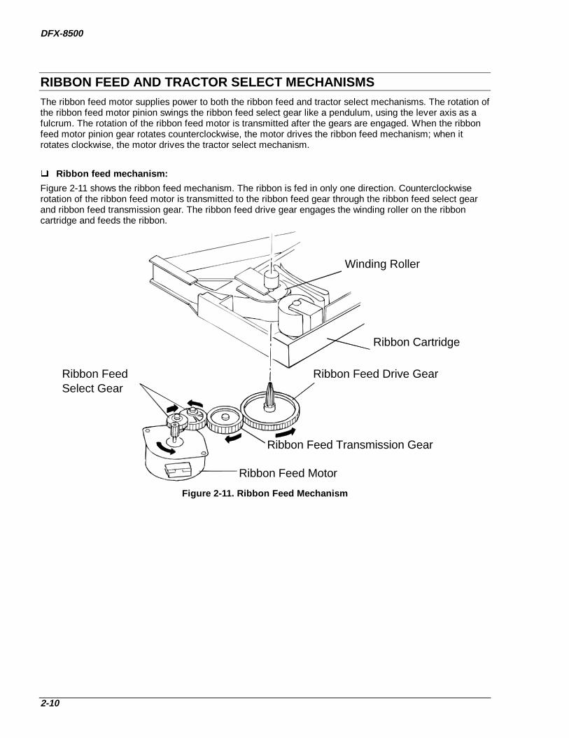
DFX-8500
2-10
RIBBON FEED AND TRACTOR SELECT MECHANISMSThe ribbon feed motor supplies power to both the ribbon feed and tractor select mechanisms. The rotation ofthe ribbon feed motor pinion swings the ribbon feed select gear like a pendulum, using the lever axis as afulcrum. The rotation of the ribbon feed motor is transmitted after the gears are engaged. When the ribbonfeed motor pinion gear rotates counterclockwise, the motor drives the ribbon feed mechanism; when itrotates clockwise, the motor drives the tractor select mechanism.
Ribbon feed mechanism:
Figure 2-11 shows the ribbon feed mechanism. The ribbon is fed in only one direction. Counterclockwiserotation of the ribbon feed motor is transmitted to the ribbon feed gear through the ribbon feed select gearand ribbon feed transmission gear. The ribbon feed drive gear engages the winding roller on the ribboncartridge and feeds the ribbon.
Ribbon Feed Select Gear
Ribbon Feed Drive Gear
Ribbon Feed Transmission Gear
Ribbon Feed Motor
Ribbon Cartridge
Winding Roller
Figure 2-11. Ribbon Feed Mechanism

OPERATING PRINCIPLES
2-11
Tractor select mechanism :
Figure 2-12 shows the operation of the tractor select mechanism. When the ribbon feed motor turnsclockwise, it rotates the ribbon feed select gear, which turns the tractor select transmission gear. Thesegears rotate the tractor select cam clockwise. A spring holds the tractor select lever against the cam; whenthe cam rotates, the tractor select lever moves horizontally.
When the tractor select lever moves to the left, the tractor select gear engages the rear tractor gear train,and the paper feed motor rotates the rear tractor. When the tractor select lever moves to the right, thetractor select gear engages the front tractor. The tractor select sensor is a relay that contacts the cam andcloses when it reaches the convex portion. (See Figure 2-12.)
The ribbon jam sensor is used to detect ribbon jams and count the length of ribbon used.
Tractor Drive Gear
Tractor Select GearHolder
Tractor Select Sensor
Ribbon Feed Select Gear
Ribbon FeedMotor
Tractor Select Cam
Tractor Select Lever Upper
Tractor Select Lever Lower
Tractor Select Transmission Gear
Tractor SelectTransmission Gear
Convex portion of cam
Ribbon Jam Sensor Ribbon Feed Gear
Figure 2-12. T ractor Select Mechanism

DFX-8500
2-12
PLUNGER MECHANISMFigure 2-13 shows the plunger mechanism. The paper bail lever is attached to the end of the plunger's ironcore. The paper bail shaft is connected to the frame. When current to the plunger coil is interrupted, theforce of the paper bail spring returns the paper bail to its original position.
Paper Bail Lever
Plunger
Iron Core
Coil
Tension Spring
Figure 2-13. Plunger Mechanism
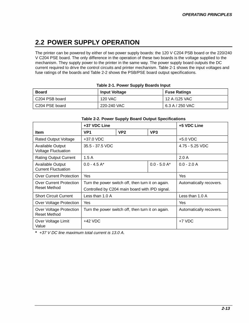
OPERATING PRINCIPLES
2-13
2.2 POWER SUPPLY OPERATIONThe printer can be powered by either of two power supply boards: the 120 V C204 PSB board or the 220/240V C204 PSE board. The only difference in the operation of these two boards is the voltage supplied to themechanism. They supply power to the printer in the same way. The power supply board outputs the DCcurrent required to drive the control circuits and printer mechanism. Table 2-1 shows the input voltages andfuse ratings of the boards and Table 2-2 shows the PSB/PSE board output specifications.
Table 2-1. Power Supply Boards Input
Board Input Voltage Fuse Ratings
C204 PSB board 120 VAC 12 A /125 VAC
C204 PSE board 220-240 VAC 6.3 A / 250 VAC
Table 2-2. Power Supply Board Output Specifications
+37 VDC Line +5 VDC Line
Item VP1 VP2 VP3
Rated Output Voltage +37.0 VDC +5.0 VDC
Available OutputVoltage Fluctuation
35.5 - 37.5 VDC 4.75 - 5.25 VDC
Rating Output Current 1.5 A 2.0 A
Available OutputCurrent Fluctuation
0.0 - 4.5 A* 0.0 - 5.0 A* 0.0 - 2.0 A
Over Current Protection Yes Yes
Over Current ProtectionReset Method
Turn the power switch off, then turn it on again.
Controlled by C204 main board with /PD signal.
Automatically recovers.
Short Circuit Current Less than 1.0 A Less than 1.0 A
Over Voltage Protection Yes Yes
Over Voltage ProtectionReset Method
Turn the power switch off, then turn it on again. Automatically recovers.
Over Voltage LimitValue
+42 VDC +7 VDC
* +37 V DC line maximum total current is 13.0 A.
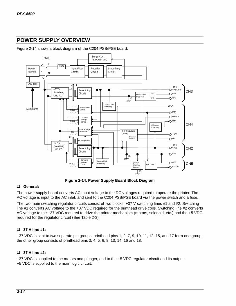
DFX-8500
2-14
POWER SUPPLY OVERVIEWFigure 2-14 shows a block diagram of the C204 PSB/PSE board.
FusePower Switch.
AC Inlet
AC Source
Input FilterCircuit
RectifierCircuit
Surge Cut (at Power On)
SmoothingCircuit
+37 V SwitchingLine #1
+37 V Switching Line #2
SmoothingCircuit
PC101Power DownControl
+37 V(VP1/VP2)
PC102
ConstantVoltageControl
Current LimitMonitoring
Over CurrentProtection
GP1
GP2
GP1
GP2
CL
PD
PC1Over VoltageProtection
+5 V Regulator
SmoothingCircuit
PC201
ConstantVoltageControl
Current LimitMonitoring
+37 V(VP3)
GP3
DRERR
Fan DriverGP3
FANDR
+5 V Regulator Circuit +5 V
GL
GP
GL
AbnormalCurrent (VP1/VP2)Monitoring
GP
VP3 DownMonitoring
SD
CN3
CN4
CN2
CN5
CN1
L
N
T1
T2 OvercurrentProtection
Figure 2-14. Power Supply Board Block Diagram
General:
The power supply board converts AC input voltage to the DC voltages required to operate the printer. TheAC voltage is input to the AC inlet, and sent to the C204 PSB/PSE board via the power switch and a fuse.
The two main switching regulator circuits consist of two blocks, +37 V switching lines #1 and #2. Switchingline #1 converts AC voltage to the +37 VDC required for the printhead drive coils. Switching line #2 convertsAC voltage to the +37 VDC required to drive the printer mechanism (motors, solenoid, etc.) and the +5 VDCrequired for the regulator circuit (See Table 2-3).
37 V line #1:
+37 VDC is sent to two separate pin groups; printhead pins 1, 2, 7, 9, 10, 11, 12, 15, and 17 form one group;the other group consists of printhead pins 3, 4, 5, 6, 8, 13, 14, 16 and 18.
37 V line #2:
+37 VDC is supplied to the motors and plunger, and to the +5 VDC regulator circuit and its output.+5 VDC is supplied to the main logic circuit.

OPERATING PRINCIPLES
2-15
Cooling fan:
The C204 PSB/PSE board includes a cooling fan that is driven by +37 VDC. The fan lowers the temperatureof the PSB/PSE board circuit components and the carriage motor.
Table 2-3. PSB/PSE Board Output DC Voltages
Voltage Board Application
+37 V (Voltage Point 1 - GroundPoint 1)
C204 DRV-B Printhead driver circuit #1
+37 V (VP2-GP2) C204 Main Printhead driver circuit #2
+37 V (VP3-GP3) C204 DRV Carriage motor
Paper feed motor
Platen gap motor
Ribbon feed motor
Head fan
Carriage fan
Plunger
Optional cutter motor
C204 PSB/PSE Cooling fan on the PSB/PSE unit
+5 V – GL C204 Main
C204 DRV
C204 DRV-B
C204 PNL
All logic systems operating voltage
Paper feed motor hold voltage
Plunger hold voltage
Platen gap motor hold voltage
Power for all the sensors
VX - GL C204 Main
C204 DRV
C204 DRV-B
Voltage for power system pull-up. It isswitched by VXCNT signal of the CPU (IC2).
Protection circuits:
These +37 VDC line blocks perform voltage control. They limit current, and prevent voltage from becomingtoo high.
Control and status signals:
The PSB/PSE board receives two control signals from the C204 main board and outputs two status signalsto the main board. See Table 2-4 for the meaning of each signal.
Fatal error recovery:
When the printer detects a fatal error, the PSB/PSE board is shut down for approximately 10 minutes by theDRERR signal. You must wait 10 minutes before turning the power on again.

DFX-8500
2-16
Table 2-4. PSB/PSE Board Control Signals
Signal Input/Output*
Signal L evel LogicSignal
Function
Block 1 † Block 2 ‡
/PD
(Power Down)
In TTL High
Low
37 VDC
0 VDC
37 VDC, 5 VDC
37 VDC, 5 VDC
DRERR
(Printhead coil/drivererror)
In TTL High
Low
0 VDC
37 VDC
0 VDC, 0 VDC
37 VDC, 5 VDC
/SD
(Source D own)
Out TTL High
Low
Undefined > 30 VDC, 5 VDC
< 30 VDC, 5 VDC
CL
(Current Limit §)
Out TTL High
Low
37 VDC
< 35 VDC
37 VDC, 5 VDC
< 35 VDC, 5 VDC
* From the view of the PSB/PSE board.
† VP1-GP1 and VP2-GP2.
‡ VP3-GP3 and +5V-GL.
§ Due to high duty printing.

OPERATING PRINCIPLES
2-17
2.3 CONTROL CIRCUITSFigure 2-15 shows a block diagram of the control circuits, with the C204 main board at the center.
CONTROL CIRCUIT OPERATION OVERVIEWThe core of the control circuit is the TMP95C061AF CPU (IC2). This CPU is driven using a 24.57 MHzexternal clock (CRU1). The CPU executes programs stored in the PROM (IC5). The CPU starts executing aprogram upon receiving the reset signal from an external device via the gate array E05B36 (IC1). The CPUaccesses the internal and external RAM (IC14). The CPU also controls the EEPROM (IC11), used to storeparameters, such as the tear-off position, while the printer is turned off.
The CPU controls all printer operations via the peripheral IC E05B36 (IC1). The main functions of theE05B36 (IC1) are:
/CS (Chip Select) signal creation Address decoding and latching Clock pulse creation Printhead driver control Carriage driver control Encoder pulse circuit control Platen gap and HF phase signal creation Interface control Monitoring of the carriage and paper feed motor drivers for abnormal current. Reset signal creation PSB/PSE board control LED control Reading the DIP switch settings on the C204 SUB boardSignals such as DRERR (driver error) and PD (power down), are sent to the C204 PSB/PSE board toprovide back-up control of the EEPROM (when the printer is turned off) and control of the power supplyvoltage. When the CPU receives a POFF or CL signal, the CPU turns off the power supply voltage of theC204 PSB/PSE board by outputting a /PD signal.
The reset circuit outputs the reset signal when the printer is turned on or off, the voltage level drops, or areset signal is input from an external device. It resets the control circuit for a certain period, directly or viathe gate array (E05B36).
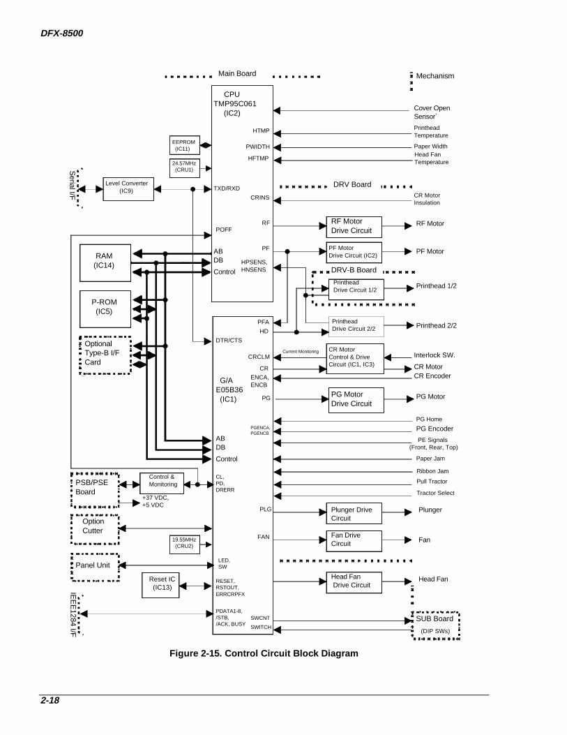
DFX-8500
2-18
PrintheadDrive Circuit 1/2
Control & Monitoring
+37 VDC,+5 VDC
PrintheadTemperature
Paper Width
PG Encoder
PE Signals(Front, Rear, Top)
Paper Jam
Pull Tractor
Tractor Select
Head FanTemperature
Current Monitoring
CR MotorInsulation
PSB/PSE Board
OptionCutter
Panel Unit
Reset IC (IC13)IE
EE
1284 I/F
ABDB
Control
G/AE05B36 (IC1)
ENCA,ENCB
CRCLM
PG MotorDrive Circuit
CR MotorControl & DriveCircuit (IC1, IC3)
CRINS
PF MotorDrive Circuit (IC2)
RF MotorDrive Circuit
ABDB
Control
OptionalType-B I/FCard
P-ROM (IC5)
RAM (IC14)
Level Converter (IC9)
Serial I/F
EEPROM (IC11)
24.57MHz (CRU1)
HPSENS,HNSENS
CPUTMP95C061 (IC2)
Printhead 2/2
Printhead 1/2
Cover OpenSensor`
DRV-B Board
DRV Board
RF Motor
PF Motor
Interlock SW.
CR MotorCR Encoder
PG Motor
Plunger DriveCircuit
Head Fan Drive Circuit
Fan Drive Circuit Fan
Head Fan
Plunger
HD
PG
CR
PGENCA,PGENCB
Ribbon Jam
PLG
HFTMP
PWIDTH
HTMP
RF
PF
TXD/RXD
DTR/CTS
POFF
CL,PD,DRERR
LED,SW
RESET,RSTOUT,ERRCRPFX
PFA
FAN
Main Board Mechanism
19.55MHz (CRU2)
SUB BoardSWITCH
SWCNT
(DIP SWs)
PG Home
PDATA1-8,/STB,/ACK, BUSY
PrintheadDrive Circuit 2/2
Figure 2-15. Control Circuit Block Diagram
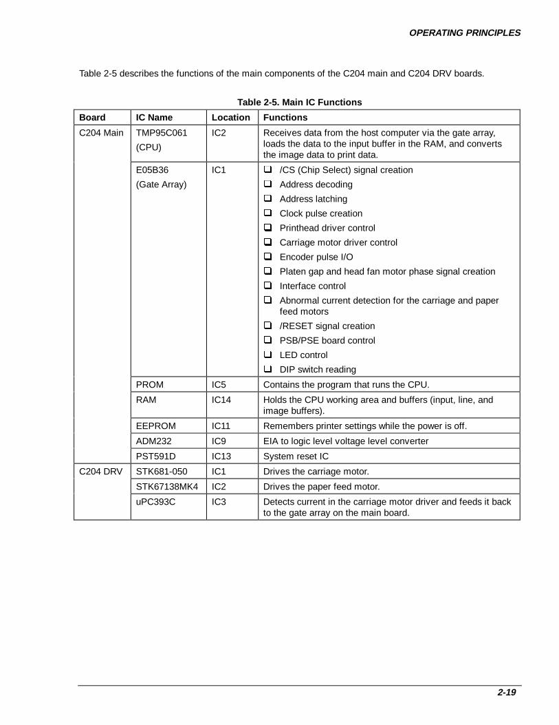
OPERATING PRINCIPLES
2-19
Table 2-5 describes the functions of the main components of the C204 main and C204 DRV boards.
Table 2-5. Main IC Functions
Board IC Name Location Functions
C204 Main TMP95C061
(CPU)
IC2 Receives data from the host computer via the gate array,loads the data to the input buffer in the RAM, and convertsthe image data to print data.
E05B36
(Gate Array)
IC1 /CS (Chip Select) signal creation
Address decoding
Address latching
Clock pulse creation
Printhead driver control
Carriage motor driver control
Encoder pulse I/O
Platen gap and head fan motor phase signal creation
Interface control
Abnormal current detection for the carriage and paperfeed motors
/RESET signal creation
PSB/PSE board control
LED control
DIP switch reading
PROM IC5 Contains the program that runs the CPU.
RAM IC14 Holds the CPU working area and buffers (input, line, andimage buffers).
EEPROM IC11 Remembers printer settings while the power is off.
ADM232 IC9 EIA to logic level voltage level converter
PST591D IC13 System reset IC
C204 DRV STK681-050 IC1 Drives the carriage motor.
STK67138MK4 IC2 Drives the paper feed motor.
uPC393C IC3 Detects current in the carriage motor driver and feeds it backto the gate array on the main board.

DFX-8500
2-20
Figure 2-16 shows the data flow through the parallel interface. Although various circuits perform dataprocessing, the control core is the CPU, where all operations are executed. In this circuit, the E05B36 IC(IC1) provides the interface between the external host computer and the CPU, and all data processing isperformed by read/write operations to MMIO (Memory Mapped Input/Output).
Data from the host computer is accepted and stored (latched) by repeating steps 1 through 3 below.
1. Upon receiving the /STROBE pulse, IC1 latches the data into ports PDATA 1 - 8 and sets the BUSYsignal to HIGH.
2. The CPU reads the latched data from the MMIO port, checks whether the data is a print command (CRcode), and stores it in the input data buffer if it is not.
3. After checking the data, the CPU makes IC1 clear the BUSY signal and output the /ACKNLG signal, viathe MMIO accesses. When either a CR code is received or the input data buffer becomes full, the CPUsets the BUSY signal to HIGH and executes printing.
4. The CPU reads the data from the input data buffer, analyzes each byte to determine whether it is acharacter or a command, and converts it to print data. The print data consists of 1-byte character codesand 2-byte attributes. Character data is stored as character codes and commands or character types arestored as attributes.
5. The print data is stored in the line buffer in units of one line of data.
6. The CPU reads the print data stored in the line buffer byte by byte, accesses the CG (CharacterGenerator), and turns the ASCII data into dots in the image buffer (or in the case of downloadedcharacters, in the download CG). A row of dots is output to the printhead control circuit as printhead data.
Note: The data flow from the Type-B I/F card is the same as the data flow from the parallel interface,described above, except the signal names and data access method differ.
MMIO
CR command ?
/STROBE
DATA
BUSY, /ACK
3
1 2
E05B36 (IC1) CPU (IC2)
DATA
No
Yes
DATABuffer full ?
Yes
RAM (IC3)
Input Data Buffer
CPU (IC2)
4
5Line Buffer
Command Analyzer
Attribute
Character Generator
Download
Image Buffer
68
7E05B36
Controls printer mechanism.
STBINT
Figure 2-16. P arallel Interface Data Flow
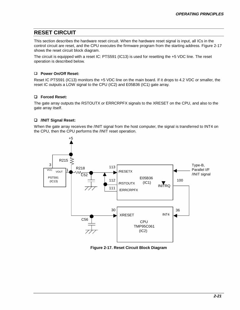
OPERATING PRINCIPLES
2-21
RESET CIRCUITThis section describes the hardware reset circuit. When the hardware reset signal is input, all ICs in thecontrol circuit are reset, and the CPU executes the firmware program from the starting address. Figure 2-17shows the reset circuit block diagram.
The circuit is equipped with a reset IC: PTS591 (IC13) is used for resetting the +5 VDC line. The resetoperation is described below.
Power On/Off Reset:
Reset IC PTS591 (IC13) monitors the +5 VDC line on the main board. If it drops to 4.2 VDC or smaller, thereset IC outputs a LOW signal to the CPU (IC2) and E05B36 (IC1) gate array.
Forced Reset:
The gate array outputs the RSTOUTX or ERRCRPFX signals to the XRESET on the CPU, and also to thegate array itself.
/INIT Signal Reset:
When the gate array receives the /INIT signal from the host computer, the signal is transferred to INT4 onthe CPU, then the CPU performs the /INIT reset operation.
+5
1
30XRESET
/RESETX
/RSTOUTX
Type-B, Parallel I/F /INIT signal
E05B36 (IC1)
CPUTMP95C061 (IC2)
PST591 (IC13)
R218
C52
/ERRCRPFX
R215
C56
113
112
111INITRQ
100
INT436
3
VOUTVCC
Figure 2-17. Reset Circuit Block Diagram
DFX-8500
2-22
SENSOR CIRCUITSFigure 2-18 shows the sensor circuits in block diagram form. The printer has the following sensors:
1. Front and rear paper end sensors (photo interrupter)
2. Top paper end sensor (photo interrupter detects the TOF position)
3. Paper jam sensor (magnetic transistor)
4. Tractor select sensor (micro mechanical switch)
5. Pull tractor sensor (micro mechanical switch)
6. Carriage encoder sensor (photo interrupter)
7. Platen gap encoder sensor (photo interrupter)
8. Platen gap home sensor (micro mechanical switch)
9. Ribbon jam sensor (photo interrupter)
10. Cover open sensor (micro mechanical switch)
11. Printhead temperature sensor (thermistor)
12. Head fan temperature sensor (thermistor)
13. Paper width sensor (photo reflector)
14. Carriage motor isolation resistance sensor (monitored by the analog port of the CPU)
15. PSB/PSE board power off sensor (signal interface)
16. Top cover sensor (Hall effect sensor)
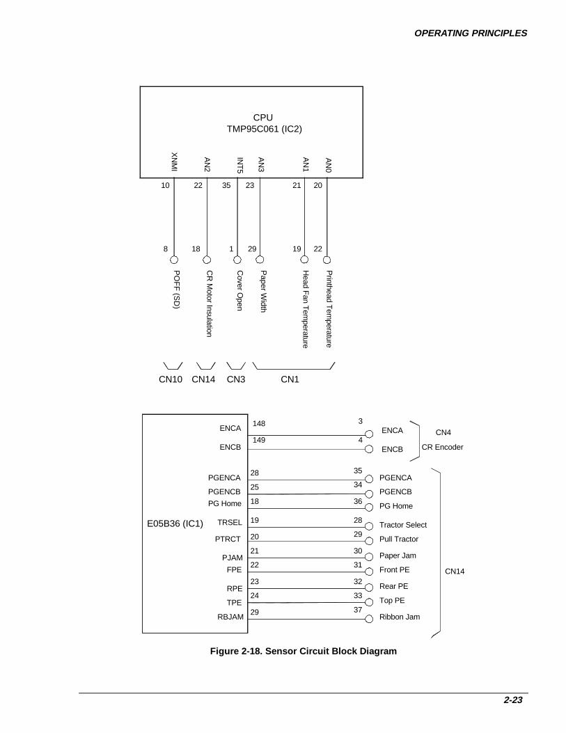
OPERATING PRINCIPLES
2-23
E05B36 (IC1)
CN4ENCA
ENCB CR Encoder
3
4
CN14
PGENCA
PGENCB
35
34
148
149
ENCA
ENCB
PGENCA
PGENCB
28
25
CN14
CPUTMP95C061 (IC2)
AN
0
AN
1
AN
2
AN
3
202122 23
Printhead T
emperature
Head F
an Tem
perature
CR
Motor Insulation
Paper W
idth
INT
5
35
Cover O
pen
CN3
1
CN1
221929
Tractor Select
Pull Tractor
28
29
TRSEL
PTRCT
19
20
Paper Jam
Front PE
30
31PJAM
FPE
21
22
Rear PE
Top PE
32
33RPE
TPE
23
24
PG Home
Ribbon Jam37
RBJAM29
3618PG Home
18
CN10X
NM
I
10
PO
FF
(SD
)
8
Figure 2-18. Sensor Circuit Block Diagram
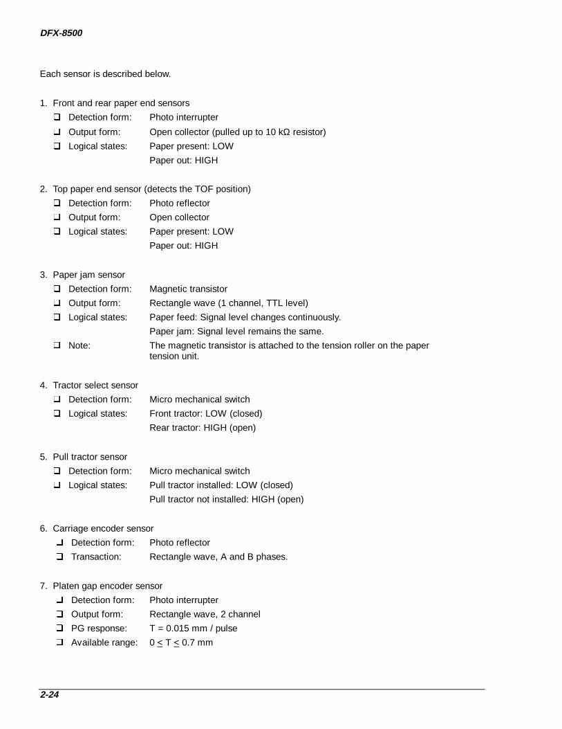
DFX-8500
2-24
Each sensor is described below.
1. Front and rear paper end sensors
Detection form: Photo interrupter
Output form: Open collector (pulled up to 10 kΩ resistor)
Logical states: Paper present: LOW
Paper out: HIGH
2. Top paper end sensor (detects the TOF position)
Detection form: Photo reflector
Output form: Open collector
Logical states: Paper present: LOW
Paper out: HIGH
3. Paper jam sensor
Detection form: Magnetic transistor
Output form: Rectangle wave (1 channel, TTL level)
Logical states: Paper feed: Signal level changes continuously.
Paper jam: Signal level remains the same.
Note: The magnetic transistor is attached to the tension roller on the paper tension unit.
4. Tractor select sensor
Detection form: Micro mechanical switch
Logical states: Front tractor: LOW (closed)
Rear tractor: HIGH (open)
5. Pull tractor sensor
Detection form: Micro mechanical switch
Logical states: Pull tractor installed: LOW (closed)
Pull tractor not installed: HIGH (open)
6. Carriage encoder sensor
Detection form: Photo reflector
Transaction: Rectangle wave, A and B phases.
7. Platen gap encoder sensor
Detection form: Photo interrupter
Output form: Rectangle wave, 2 channel
PG response: T = 0.015 mm / pulse
Available range: 0 < T < 0.7 mm

OPERATING PRINCIPLES
2-25
8. Platen Gap home position sensor
Detection form: Micro mechanical switch
Logical states: Home: LOW (closed)
Out of home: HIGH (open)
9. Ribbon jam sensor
Detection form: Photo interrupter
Function: The main board monitors signal changes during ribbon feed.
10. Cover open sensor
Detection form: Micro mechanical switch
Logical: Cover closed: LOW
Cover open: HIGH
11. Printhead temperature sensor (thermistor)
This thermistor is on the printhead.
12. Head fan temperature sensor (thermistor)
This thermistor is on the printhead fan.
13. Paper width sensor
Detection form: Photo reflector
Output form: Emitter follower
Logical states: No paper present: Standard voltage level.
Paper present: The voltage level is double the standard voltage level.
14. Carriage motor isolation resistance sensor (monitored by port AN2 of the CPU)
To provide information about the carriage motor life, the analog port (AN2) of the CPU checks the isolation resistance every time the printer is turned on. If the isolation resistance is equal or less than 2.2 kΩ, a carriage error is detected and the printer beeps.
15. PSB/PSE Board power off sensor (signal interface)
When the +37 VDC line voltage drops, the PSB/PSE board sends a HIGH POFF signal to the main board.
16. Top Cover Sensor (Hall effect sensor)
When the cover is open, the printer emits a 3 beep code and the +35 V line voltage drops.

DFX-8500
2-26
CARRIAGE MOTOR DRIVE CIRCUITFigure 2-19 shows the internal circuit of the carriage motor. Table 2-6 provides the carriage motorspecification. Figure 2-20 shows a block diagram of the carriage motor drive circuit.
An STK681-050 (IC1) bipolar driver IC drives the carriage motor. It has built-in bipolar switching transistorsand a current limiter. A uPC393C comparator (IC3) monitors the current in the carriage motor driver IC(IC1). If the current exceeds the set value, it is fed back to the gate array (E05B36). The gate array thenoutputs the signal for the current setting transistors (Q5, Q6, and Q7).
When the printer is turned on, CPU analog port AN2 measures the isolation resistance in the carriage motor.If the isolation resistance is equal or less than 2.2 kΩ, the printer displays a carriage error.
If the printer cover is open during power on, the interlock switch cuts the carriage motor driver power.
The ENCA pulse that the carriage encoder outputs is input to the general purpose port CRENCA of the gatearray, and the ENCB pulse that the carriage encoder outputs is input to general purpose port CRENCB ofthe gate array. The gate array counts these pulses using the internal counter and determines the amountand direction of motor rotation.
Table 2-6. Carriage Motor Specificat ions
Specification Description
Form DC servo motor
Supply Voltage +37 VDC
Internal CoilResistance
1.66 Ω (+10%)
CurrentConsumption*
Acceleration / Deceleration:4.6 A (average)
Constant Speed:
2.5 A (average)
* during Super draft printing, +10%
Motor
Q2
Q3Q1
Q4
VP3 (+37 VDC)
GP3 (GND)
R1
Figure 2-19. Carriage Motor Internal Circuit

OPERATING PRINCIPLES
2-27
E05B36
CRAX
STK681-050(IC1)
IN_A
VP3
VCC1
OUT1
CR B
Vref
ZD14.3 V
A OUT
AIN+
AIN-
CR
I0
CR
I1
CR
I2C
RE
NC
B
CR
EN
CA
VCC1
OUT2
CR A
IN_B
IN_C
IN_D
CRCLK
Q16,Q17,Q18,Q19
VX
CRBXCRCXCRDX
CLK
Q34,Q35,ZD2
VX
CR
CLM
Q5,Q6,Q7
GPGP
Vref
+5V
GP3
GP3
Vx
CPUTMP85C061 (IC2) AN2
CRINS
CRCLM
D3
uPC393C(IC3)
Partial PressureCircuit
Interlock Switch
Carriage Motor
Carriage Encoder Sensor
ENCA
ENCBMainBoard
DRVBoard
Figure 2-20. Carriage Motor Drive Circuit Block Diagram

DFX-8500
2-28
Table 2-7 lists the carriage motor drive modes.
Table 2-7. Carriage Motor Drive Modes
Action Drive Mode Carriage MotorSpeed (rpm)
Accelerat ion /Decelerat ion ControlCurve*
ConstantSpeedControl
Carriage moves Super Draft 2800 Acceleration and Carriagemotor pulsecontrol
and prints.† Super Draft HD 2666 Deceleration 1
Draft 2100
Draft HD 2000
Bit image 1 1050 Acceleration and
Bit image 2 1050 Deceleration 3
Bit image 3 1050
NLQ 1050
NLQ HD 1000
Super Draft × 1/3 888
Bit image 4 933
Draft × 1/3 666
Bit image 1 × 1/3 555
Bit image 2 × 1/3 500
Bit image 3 × 1/3 444
NLQ × 1/3 333
Draft × 1/6 333
Bit image 4 × 1/3 277
Bit image 3 × 1/6 222
Carriage moveswithout printing.
Home positionseek
500
Paper widthdetection seek
500
Logical seek 0 2100
Logical seek 1 1050
Logical seek 2 333
Measurement seek —
* See Table 2-8.
† This action includes all printing modes. Carriage motor pulse control adjusts the carriage speed. (Seebelow for more information on carriage motor pulse control.) For increased throughput, printing is allowedwhen accelerating or decelerating between the Super Draft and Draft HD drive modes.
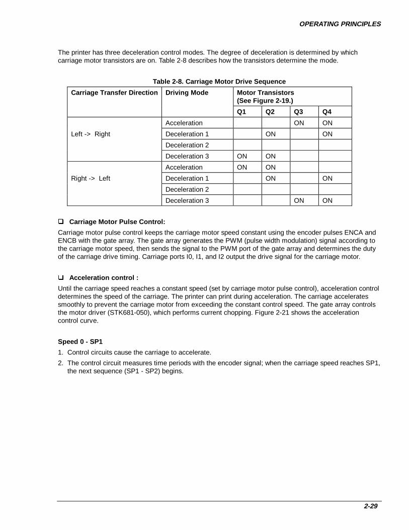
OPERATING PRINCIPLES
2-29
The printer has three deceleration control modes. The degree of deceleration is determined by whichcarriage motor transistors are on. Table 2-8 describes how the transistors determine the mode.
Table 2-8. Carriage Motor Drive Sequence
Carriage Transfer Direction Driv ing Mode Motor Transistors(See Figure 2-19.)
Q1 Q2 Q3 Q4
Acceleration ON ON
Left -> Right Deceleration 1 ON ON
Deceleration 2
Deceleration 3 ON ON
Acceleration ON ON
Right -> Left Deceleration 1 ON ON
Deceleration 2
Deceleration 3 ON ON
Carriage Motor Pulse Control:
Carriage motor pulse control keeps the carriage motor speed constant using the encoder pulses ENCA andENCB with the gate array. The gate array generates the PWM (pulse width modulation) signal according tothe carriage motor speed, then sends the signal to the PWM port of the gate array and determines the dutyof the carriage drive timing. Carriage ports I0, I1, and I2 output the drive signal for the carriage motor.
Accelerat ion control :
Until the carriage speed reaches a constant speed (set by carriage motor pulse control), acceleration controldetermines the speed of the carriage. The printer can print during acceleration. The carriage acceleratessmoothly to prevent the carriage motor from exceeding the constant control speed. The gate array controlsthe motor driver (STK681-050), which performs current chopping. Figure 2-21 shows the accelerationcontrol curve.
Speed 0 - SP1
1. Control circuits cause the carriage to accelerate.
2. The control circuit measures time periods with the encoder signal; when the carriage speed reaches SP1,the next sequence (SP1 - SP2) begins.

DFX-8500
2-30
SP1 - SP2
1. When the carriage speed reaches SP1, the printer uses the acceleration driving mode, based on the dutydata, and the rest of the time, it uses deceleration driving mode 2.
2. During deceleration driving mode 2, the control circuit measures time periods using the encoder signal,and controls the following:
If duty data reaches Dutymin before the carriage speed reaches SP2, the next sequence (SP2-SPref)begins when the carriage speed reaches SP2.
If the carriage speed reaches SP2 before duty data reaches Dutymin, the next sequence (SP2-SPref)begins.
SP2 - SPref
When the carriage speed reaches SP2, carriage motor pulse control oversees the carriage speed.
0
SP1
SP2
SPref
Acceleration
Deceleration 2
Con
trol
Sig
nal
Constant Speed Control
Acc
eler
atio
n C
urve
Figure 2-21. Carriage Motor Drive Circuit Block Diagram
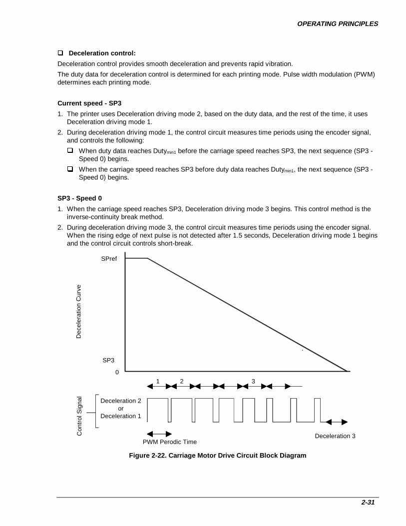
OPERATING PRINCIPLES
2-31
Decelerat ion control:
Deceleration control provides smooth deceleration and prevents rapid vibration.
The duty data for deceleration control is determined for each printing mode. Pulse width modulation (PWM)determines each printing mode.
Current speed - SP3
1. The printer uses Deceleration driving mode 2, based on the duty data, and the rest of the time, it usesDeceleration driving mode 1.
2. During deceleration driving mode 1, the control circuit measures time periods using the encoder signal,and controls the following:
When duty data reaches Dutymin1 before the carriage speed reaches SP3, the next sequence (SP3 -Speed 0) begins.
When the carriage speed reaches SP3 before duty data reaches Dutymin1, the next sequence (SP3 -Speed 0) begins.
SP3 - Speed 0
1. When the carriage speed reaches SP3, Deceleration driving mode 3 begins. This control method is theinverse-continuity break method.
2. During deceleration driving mode 3, the control circuit measures time periods using the encoder signal.When the rising edge of next pulse is not detected after 1.5 seconds, Deceleration driving mode 1 beginsand the control circuit controls short-break.
0
SPref
SP3
Deceleration 2 or Deceleration 1
Con
trol
Sig
nal
PWM Perodic Time
1 2 3
Deceleration 3
Dec
eler
atio
n C
urve
Figure 2-22. Carriage Motor Drive Circuit Block Diagram

DFX-8500
2-32
PAPER FEED MOTOR DRIVE CIRCUITStepping motor driver STK6713BMK4 (IC2) drives the paper feed motor. Figure 2-22 shows the paper feedmotor drive circuit block diagram, and Table 2-9 contains motor specifications.
Table 2-9. Paper Feed Motor Specifications
Specification Description
Form 4-phase, 200-pole, hybrid pulse motor
Supply Voltage +37 VDC (applied to the drive circuit)
Internal Coil Resistance 2.8 Ω +10% per phase at 25 oC
Frequency Normal mode, constant driving:4274 pulses per second (pps), 9.9 inches per second (ips)
Middle speed mode, constant driving:2610 pps, 6 ips
Current Consumption Driving: 1.75 A, + 0.20 A per phase (average)
Holding: 0.26 A, + 0.20 A per phase (average)
The motor pulse switching signals are transmitted from CPU ports PG00 to PG03. The paper feed motor iscontrolled using open-loop phase switching based on the specified time data. The phase driving method is1-2 phase excitation. (When the paper feed motor is held, the phase driving method is 1-phase excitation.)The CPU determines the paper length and whether the pull tractor is installed, then selects the most suitabledriving mode from the modes below.
Micro feed (adjust) mode: < 20 / 432 inches
Middle speed mode: > 20 / 432 inches and < 60 / 432 inches, or with optional pull tractor
Normal speed mode: > 60 / 432 inches
Each phase switching FET in driver IC2 is an open collector. When the phase switching data is HIGH, themotor is turned on. The PFA port of the gate array monitors the phase A signal of the paper feed motor andchecks whether it is operating normally. The PFA port is used as the WDT (watch dog timer).
If paper feed motor operation is abnormal, the gate array outputs the /RSTOUT (reset request) signal to thesystem reset IC (IC13). See “Reset Circuit” on page 2-21.
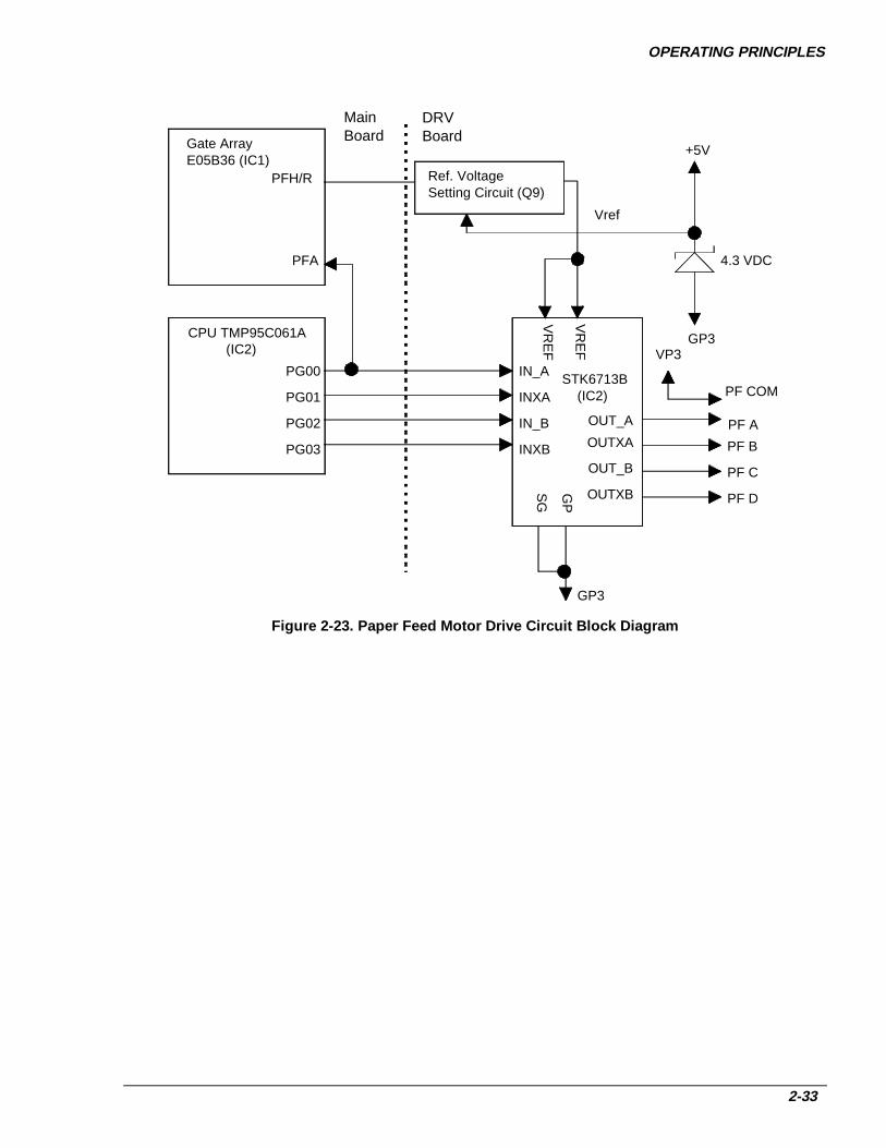
OPERATING PRINCIPLES
2-33
STK6713B (IC2)
PF A
PF B
PF C
PF D
OUT_A
OUTXA
OUT_B
OUTXB
CPU TMP95C061A (IC2)
PFH/R
PG00
PG01
PG02
PG03
VR
EF
VR
EF
PFA
+5V
GP3
4.3 VDC
Ref. Voltage Setting Circuit (Q9)
IN_A
INXA
IN_B
INXB
GP3
SG
GP
Gate Array E05B36 (IC1)
Vref
PF COM
VP3
DRV Board
MainBoard
Figure 2-23. Paper Feed Motor Drive Circuit Block Diagram

DFX-8500
2-34
RIBBON FEED MOTOR DRIVE CIRCUITFigure 2-24 shows a block diagram of the ribbon feed motor drive circuit, and Table 2-10 provides the ribbonfeed motor specifications. The ribbon feed motor is a stepping motor. The control circuit performs open-loopphase switching control according to the timing data for acceleration, constant speed, and deceleration.CPU ports PG10 to PG13 output the motor phase switching signals. The control method is not equipped witha hold circuit for changing the motor phase. The ribbon feed motor rotates when the carriage moves.
Table 2-10. Ribbon Feed Motor Specifications
Specification Description
Form 4-phase, 48-pole, PM pulse motor
Supply Voltage 37 VDC (applied to the drive circuit)
Internal Coil Resistance 150 ohms + 10 % per phase at 25 oC
Frequency 720 pps
Current Consumption Driving: 0.10 A (average)
Driving Method Constant voltage driving, 2-2 phase drive
TMP95C061A (IC2)
PG10PG11
PG12
PG13
Q22
Q23
Q24
Q25
PNP Transistor x4
RF A
RF B
RF C
RF D
DRVBoard
E05B36 (IC1) RFCOM Q20,Q21
VP 3
F1
RF COM
RF Motor
Main Board
Figure 2-24. Ribbon Feed Motor Drive Circuit Block Diagram

OPERATING PRINCIPLES
2-35
PLATEN GAP MOTOR DRIVE CIRCUITFigure 2-25 shows a block diagram of the platen gap motor drive circuit, and Table 2-11 provides platen gapmotor specifications.
The platen gap motor is a stepping motor. The motor phase switching signals are output from the gate arrayports PGA to PGD. The motor common voltage (PGCOM) alternates between drive mode (+37 VDC) andhold mode (+5 VDC), according to the PG H/R signal of the gate array. The phase driver circuit is made ofdiscrete transistors Q12 to Q15.
The phase A output pulse from the platen gap encoder (ENCA) is input to port ENCA on the gate array andthe phase B output pulse from the platen gap encoder (ENCB) is input to port ENCB on the gate array. Thegate array counts these pulses using an internal counter and determines the amount and direction of motorrotation.
Table 2-11. Platen Gap Motor Specifications
Specification Description
Form 4-phase, 48-pole, PM pulse motor
Supply Voltage 37 VDC (applied to the drive circuit)
Internal Coil Resistance 250 + 18 Ω per phase at 25 oC
Current Consumption Driving: 0.20 A (average)
Holding: 0.02 A + 5 mA
Frequency 285 pps
Driving Method Constant voltage driving, 2-2 phase drive

DFX-8500
2-36
PG H/R
PG A
PG
A
PG
B
PG
C
PG
D
PG
EN
CA
Plsten GapEncoder
Platen GapMotor
PG
CO
M
Gate ArrayE05B36 (IC1)
Q12,Q13,Q14.Q15
VP 3
F2
Q10,Q11
D10
+5V
DRV BoardMain Board
PG B
PG C
PG D
PG
EN
CB
Figure 2-25. Platen Gap Motor Drive Circuit Block Diagram
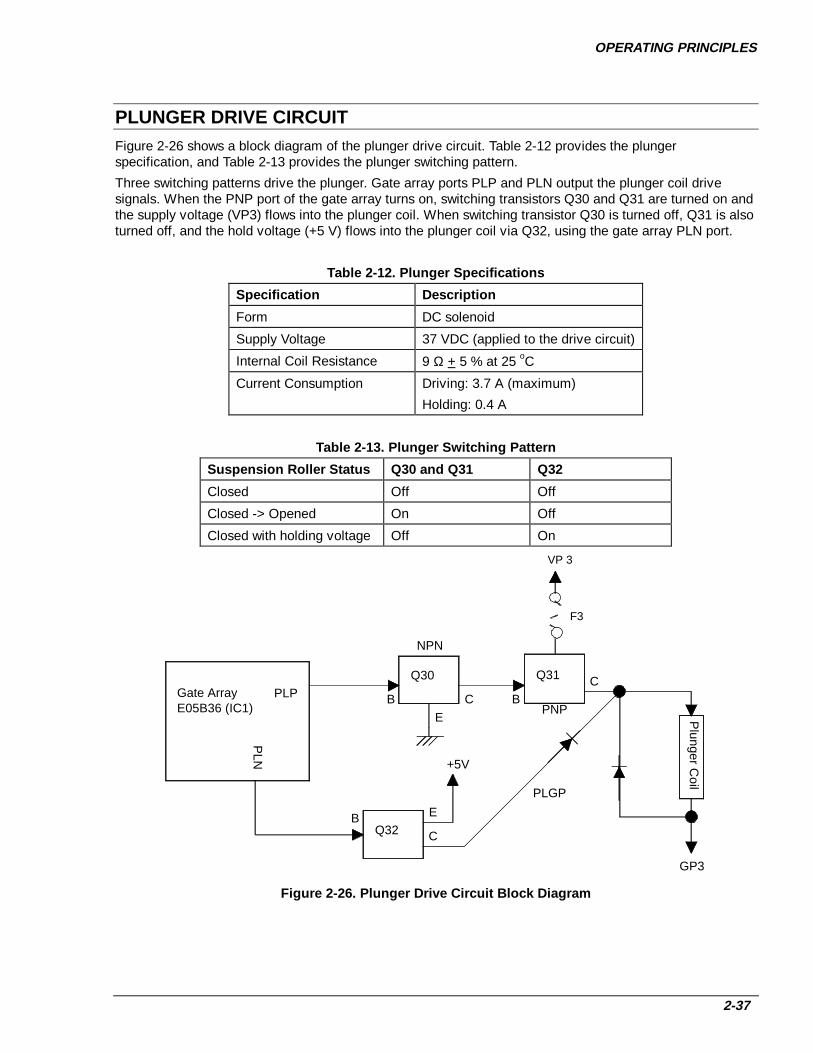
OPERATING PRINCIPLES
2-37
PLUNGER DRIVE CIRCUITFigure 2-26 shows a block diagram of the plunger drive circuit. Table 2-12 provides the plungerspecification, and Table 2-13 provides the plunger switching pattern.
Three switching patterns drive the plunger. Gate array ports PLP and PLN output the plunger coil drivesignals. When the PNP port of the gate array turns on, switching transistors Q30 and Q31 are turned on andthe supply voltage (VP3) flows into the plunger coil. When switching transistor Q30 is turned off, Q31 is alsoturned off, and the hold voltage (+5 V) flows into the plunger coil via Q32, using the gate array PLN port.
Table 2-12. Plunger Specifications
Specification Description
Form DC solenoid
Supply Voltage 37 VDC (applied to the drive circuit)
Internal Coil Resistance 9 Ω + 5 % at 25 oC
Current Consumption Driving: 3.7 A (maximum)
Holding: 0.4 A
Table 2-13. Plunger Switching Pattern
Suspension Roller Status Q30 and Q31 Q32
Closed Off Off
Closed -> Opened On Off
Closed with holding voltage Off On
Q30Gate ArrayE05B36 (IC1)
PLP
PLN
E
CB
NPN
Q31
PNPB
C
Plunger C
oil
GP3
Q32
+5V
EBC
PLGP
VP 3
F3
Figure 2-26. Plunger Drive Circuit Block Diagram

DFX-8500
2-38
PRINTHEAD DRIVE CIRCUITFigure 2-27 shows the printhead drive circuit block diagram.
General:
The print data lines from IC1 are active when they are HIGH. When ports HDR1 (HDL1) to HDR9 (HDL9) ofIC1 go HIGH, the FET gates are biased, and the FETs are turned on to send current to the printhead coil. Atthe same time, ports HDRS1 (HDLS1) to HDRS9 (HDLS9) of IC1 go HIGH, the FET gates are biased, andthe FETs are turned on. Each printhead coil is driven through the bipolar drive method. When the HD port ofIC1 goes LOW, the FET is turned off and the printhead coil current is cut.
Two +37 VDC lines (VP1-GP1 on the C204 DRV-B board and VP2-GP2 on the main board) supply thecommon voltage for the printhead coil. The VP2-GP2 line (CN1 on the main board) supplies pins 1, 2, 7, 9,10, 11, 12, 16, and 17. The VP1-GP1 line (CN1 on the C204 DRV-B board) supplies pins 3, 4, 5, 6, 8, 13,14, 15, and 18.
The CPU monitors the printhead temperature and head fan (HF) temperature. When the temperature risesabove 120 °F, printing stops at once until the temperature cools.
The CPU also monitors the printhead driver status, P-channel and N-channel FET respectively. If theprinthead driver FET shorts, CPU (IC2) port PDRERR (P-channel) / NDRERR (N-channel) detects a HIGHlevel and the E05B36 (IC1) sends the DRERR (Driver Error) signal to the C204 PSB/PSE board. When theC204 PSB/PSE board receives this signal, it stops the output voltage and the printer beeps.

OPERATING PRINCIPLES
2-39
E05B36 (IC1)
FANA
Q10
Q11
HFANA
HFANBFANAX
HD
RS
1-HD
RS
9
HD
R1-H
DR
9
HD
LS1-H
DLS
9
HD
L1-HD
L9
Printhead Driver Circuit 1/2
Printhead Coils 1/2 DRV-B Board Printhead Driver Circuit 2/2 Printhead Coils 2/2
Main Board
VX VP1 GP1 VX VP2 GP2
GP2
VP2
R100
R101
ND
RE
RR
GP2
R98
R99
ZD4
ZD1
PD
RE
RR
TMP95C061A (IC2)
Monitoring PNPs Short Circuit
Monitoring NPNs Short Circuit
24V5.1V
Printhead ThermistorHN
SE
NS
HPSENSHTMP
HF Motor ThermistorFTMP
HT
MP
FT
MP
HF Motor
Figure 2-27. Printhead Drive Circuit Block Diagram

DFX-8500
2-40
Printhead high temp erature feedback operat ion:
The printer supports the printhead temperature detection sequence, which consists of the following steps:
1. When the printhead temperature is less than 110 oC, the printer performs normal printing.
2. When the printhead temperature exceeds 110 oC, the printer performs interval printing (carriage rest timeat the sides is a little bit longer than normal).
3. When the printhead temperature exceeds 120 oC, the printer stops printing until the temperature goesdown to 100 oC or less.
4. When the printhead temperature returns to less than 100 oC, the printer prints normally again.
HF temperature feedback operat ion:
The printer supports the head fan (HF) temperature detection sequence, which consists of the followingsteps:
1. When the printhead fan temperature rises to 65 oC or above, the HF starts rotating.
2. When the printhead temperature falls to 50 oC or less, the HF stops.
CHAPTER 3DISASSEMBLY AND ASSEMBLY
3.1 OVERVIEW _________________________________________________________________ 3-13.1.1 Precautions ______________________________________________________________________ 3-13.1.2 Tools ___________________________________________________________________________ 3-33.1.3 Screw Specifications _______________________________________________________________ 3-53.1.4 Service Checks After Repair _________________________________________________________ 3-6
3.2 DISASSEMBLY AND ASSEMBLY ______________________________________________ 3-73.2.1 ROM Replacement ________________________________________________________________ 3-83.2.2 Printhead and Ribbon Mask Assembly Removal _________________________________________ 3-93.2.3 Housing Removal ________________________________________________________________ 3-13
3.2.3.1 Top Cover Removal_____________________________________________________________ 3-133.2.3.2 Left, Right, and Front Covers Removal and Fuse Replacement___________________________ 3-143.2.3.3 Front Panel Removal____________________________________________________________ 3-163.2.3.4 Upper Case Removal____________________________________________________________ 3-17
3.2.4 Circuit Board Removal ____________________________________________________________ 3-183.2.4.1 Bottom Panel Removal __________________________________________________________ 3-183.2.4.2 Fan and C204 Power Supply Board Removal_________________________________________ 3-213.2.4.3 C204 SUB Board Removal _______________________________________________________ 3-223.2.4.4 C204 DRV-B and C204 DRV Board Removal ________________________________________ 3-233.2.4.5 C204 Main Board Removal ______________________________________________________ 3-243.2.4.6 AC Inlet Removal ______________________________________________________________ 3-263.2.4.7 C204 PNL Board Removal _______________________________________________________ 3-27
3.2.5 Interlock Switch and Cover Open Sensor Removal ______________________________________ 3-283.2.6 Printer Mechanism Removal________________________________________________________ 3-29
3.2.6.1 Fan Removal __________________________________________________________________ 3-313.2.6.2 Ribbon Feed Change Lever Unit Removal___________________________________________ 3-323.2.6.3 Tractor Select Lever Disassembly__________________________________________________ 3-343.2.6.4 Ribbon Jam Sensor Removal______________________________________________________ 3-353.2.6.5 Connector Junction Board and FPC Board Removal ___________________________________ 3-363.2.6.6 Platen Gap (PG) Sensor and PG Motor Removal______________________________________ 3-373.2.6.7 Plunger and Paper Bail Removal __________________________________________________ 3-383.2.6.8 Upper Paper Guide and Top PE Sensor Removal______________________________________ 3-403.2.6.9 Tension Roller Shaft Removal ____________________________________________________ 3-413.2.6.10 Platen Removal ______________________________________________________________ 3-433.2.6.11 Paper Jam Sensor Removal_____________________________________________________ 3-443.2.6.12 Pull Tractor Sensor Removal ___________________________________________________ 3-453.2.6.13 Paper Width Sensor Removal ___________________________________________________ 3-463.2.6.14 Platen Gap Home Sensor Removal _______________________________________________ 3-473.2.6.15 Paper Feed Motor Removal_____________________________________________________ 3-493.2.6.16 Left Gear Train Removal ______________________________________________________ 3-503.2.6.17 Front Tractor Removal ________________________________________________________ 3-513.2.6.18 Rear Tractor Removal _________________________________________________________ 3-523.2.6.19 Carriage Motor Fan Removal ___________________________________________________ 3-533.2.6.20 Carriage Motor Removal_______________________________________________________ 3-543.2.6.21 Carriage Encoder Sensor Removal _______________________________________________ 3-553.2.6.22 Carriage Mechanism Disassembly _______________________________________________ 3-563.2.6.23 Paper Guide Support Plate Removal______________________________________________ 3-593.2.6.24 Platen Roller Removal_________________________________________________________ 3-59
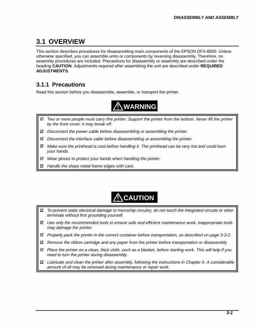
DISASSEMBLY AND ASSEMBLY
3-1
3.1 OVERVIEWThis section describes procedures for disassembling main components of the EPSON DFX-8500. Unlessotherwise specified, you can assemble units or components by reversing disassembly. Therefore, noassembly procedures are included. Precautions for disassembly or assembly are described under theheading CAUTION. Adjustments required after assembling the unit are described under REQUIREDADJUSTMENTS .
3.1.1 PrecautionsRead this section before you disassemble, assemble, or transport the printer.
Two or more people must carry this printer. Support the printer from the bottom. Never lift the printerby the front cover; it may break off.
Disconnect the power cable before disassembling or assembling the printer.
Disconnect the interface cable before disassembling or assembling the printer.
Make sure the printhead is cool before handling it. The printhead can be very hot and could burnyour hands.
Wear gloves to protect your hands when handling the printer.
Handle the sharp metal frame edges with care.
To prevent static electrical damage to microchip circuitry, do not touch the integrated circuits or otherterminals without first grounding yourself.
Use only the recommended tools to ensure safe and efficient maintenance work. Inappropriate toolsmay damage the printer.
Properly pack the printer in the correct container before transportation, as described on page 3-3-2.
Remove the ribbon cartridge and any paper from the printer before transportation or disassembly.
Place the printer on a clean, thick cloth, such as a blanket, before starting work. This will help if youneed to turn the printer during disassembly.
Lubricate and clean the printer after assembly, following the instructions in Chapter 6. A considerableamount of oil may be removed during maintenance or repair work.
WARNING
CAUTION

DFX-8500
3-2
Remove the ribbon cartridge and any paper before transporting the printer. Then attach the followingpacking materials, as shown in Figure 3-1:
Transport locking bracket Carriage guide shaft support bar Printhead protector Foam packing for paper bail
Printhead Protector
TransportationLocking Brackets
Carriage GuideSupport Bar
Foam Packing
Figure 3-1. Attaching the P acking Material
After attaching the packing materials, pack the printer in its container, as shown in Figure 3-2.
Figure 3-2. P acking the DFX- 8500
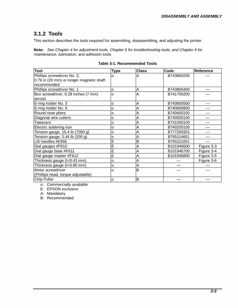
DISASSEMBLY AND ASSEMBLY
3-3
3.1.2 ToolsThis section describes the tools required for assembling, disassembling, and adjusting the printer.
Note: See Chapter 4 for adjustment tools, Chapter 5 for troubleshooting tools, and Chapter 6 formaintenance, lubrication, and adhesion tools.
Table 3-1. Recommended T ools
Tool Type Class Code ReferencePhillips screwdriver No. 2;0.79 in (20 mm) or longer magnetic shaftrecommended.
o A B743800200 —
Phillips screwdriver No. 1 o A B743800400 —Box screwdriver; 0.28 inches (7 mm)across
o A B741700200 —
E-ring holder No. 3 o A B740800500 —E-ring holder No. 6 o A B740800800 —Round nose pliers o A B740400100 —Diagonal wire cutters o A B740500100 —Tweezers o A B741000100 —Electric soldering iron o A B740200100 —Tension gauge, 15.4 lb (7000 g) o A B777200301 —Tension gauge, 0.44 lb (200 g) o A B765114601 —Lift handles #E656 E B B765111001 —Dial gauges #F610 E A B101946600 Figure 3-3Dial gauge base #F611 E A B101946700 Figure 3-4Dial gauge master #F612 E A B101946800 Figure 3-5Thickness gauge (t=0.43 mm) o A — Figure 3-6Thickness gauge (t=0.80 mm) o A — —Motor screwdriver(Phillips head, torque adjustable)
o B — —
Chip Puller o B — —o: Commercially availableE: EPSON exclusiveA: MandatoryB: Recommended
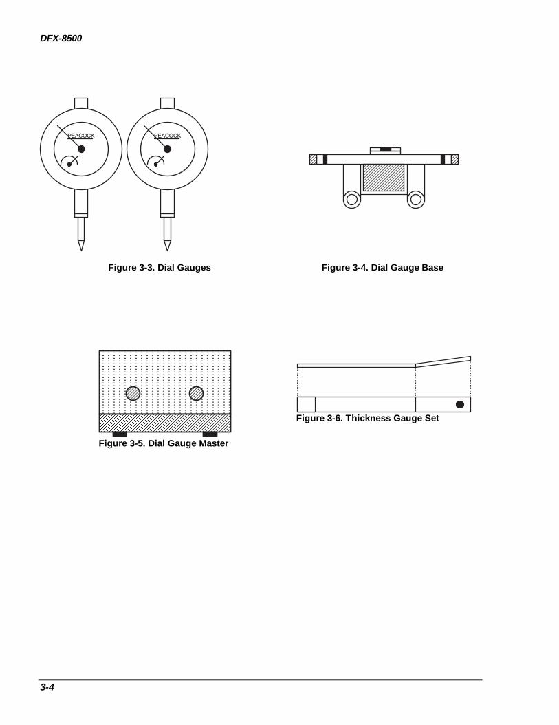
DFX-8500
3-4
P E A C O C K P E A C O C K
Figure 3-3. Dial Gauges Figure 3-4. Dial Gauge Base
Figure 3-5. Dial Gauge Master
Figure 3-6. Thickn ess Gauge Set
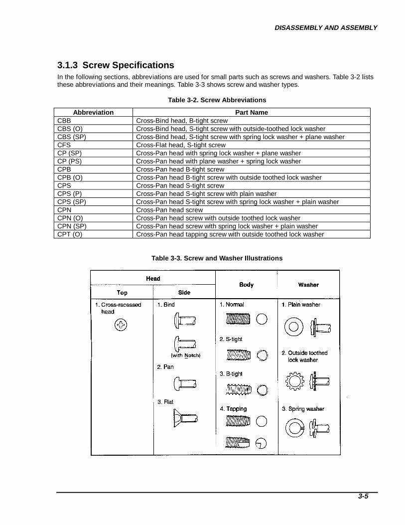
DISASSEMBLY AND ASSEMBLY
3-5
3.1.3 Screw SpecificationsIn the following sections, abbreviations are used for small parts such as screws and washers. Table 3-2 liststhese abbreviations and their meanings. Table 3-3 shows screw and washer types.
Table 3-2. Screw Abbreviat ions
Abbreviation Part NameCBB Cross-Bind head, B-tight screwCBS (O) Cross-Bind head, S-tight screw with outside-toothed lock washerCBS (SP) Cross-Bind head, S-tight screw with spring lock washer + plane washerCFS Cross-Flat head, S-tight screwCP (SP) Cross-Pan head with spring lock washer + plane washerCP (PS) Cross-Pan head with plane washer + spring lock washerCPB Cross-Pan head B-tight screwCPB (O) Cross-Pan head B-tight screw with outside toothed lock washerCPS Cross-Pan head S-tight screwCPS (P) Cross-Pan head S-tight screw with plain washerCPS (SP) Cross-Pan head S-tight screw with spring lock washer + plain washerCPN Cross-Pan head screwCPN (O) Cross-Pan head screw with outside toothed lock washerCPN (SP) Cross-Pan head screw with spring lock washer + plain washerCPT (O) Cross-Pan head tapping screw with outside toothed lock washer
Table 3-3. Screw and Washer Illustrations

DFX-8500
3-6
3.1.4 Service Checks After RepairBefore returning the printer to the customer, use the check list in Table 3-4. This checklist helps makeservicing and shipping more efficient.
Table 3-4. Inspection Ch eck List for the Repaired Printer
Category Checkpoint Passed?Maintenance Are all necessary adjustments completed? Are
the results within specified tolerances? (SeeChapter 4.)
[ ] Yes [ ] No
Have all lubricants and adhesives been properlyapplied? (See Chapter 6.)
[ ] Yes [ ] No
Operation Does the printer perform initialization correctlywhen turned on?
[ ] Yes [ ] No
Does the printer work correctly with theassociated utility program?
[ ] Yes [ ] No
ROMUpgrade
Is the ROM version up to date? [ ] Yes [ ] No
Cleaning Has all dust been removed from the inside ofthe printer?
[ ] Yes [ ] No
Is the exterior housing clean? [ ] Yes [ ] NoReturn to Is the power off? [ ] Yes [ ] Nocustomer Has the ribbon cartridge been removed? [ ] Yes [ ] NoPacking Have you included all necessary attachments
(power cord, optional units, etc.)?[ ] Yes [ ] No
DISASSEMBLY AND ASSEMBLY
3-7
3.2 DISASSEMBLY AND ASSEMBLY
Be sure to read and follow the instructions in Section 3.1, "Overview," before disassembling theprinter.
Be sure to turn the printer power off and unplug the AC cable before disassembling the printer.
This section describes how to disassemble the printer. See the Appendix for an exploded diagram of theprinter. Use this diagram for simple disassembly procedures not described here. To assemble the printer,follow the disassembly instructions in this chapter in reverse. Any extra information you need to assembleprinter components is provided in notes labeled CAUTION or REMINDER. Adjustments required beforeassembly are described in notes labeled REQUIRED ADJUSTMENT .
WARNING

DFX-8500
3-8
3.2.1 ROM Replacement
Remove the ROM carefully to avoid damaging the board.
Check the INDEX mark on the chip socket to be sure the new ROM is oriented correctly beforeinserting it. Insert the ROM chip carefully to avoid damaging the chip pins and the board.
1. Remove the top cover of the printer. (See section 3.2.3.1.)2. Lay the printer on its back.3. Remove 1 screw (CBB, M3×10) securing the ROM cover, then remove the cover.4. Remove the ROM using a chip puller.
Screw (CBB, M3×10)
Figure 3-7. ROM Repl acement
CAUTION
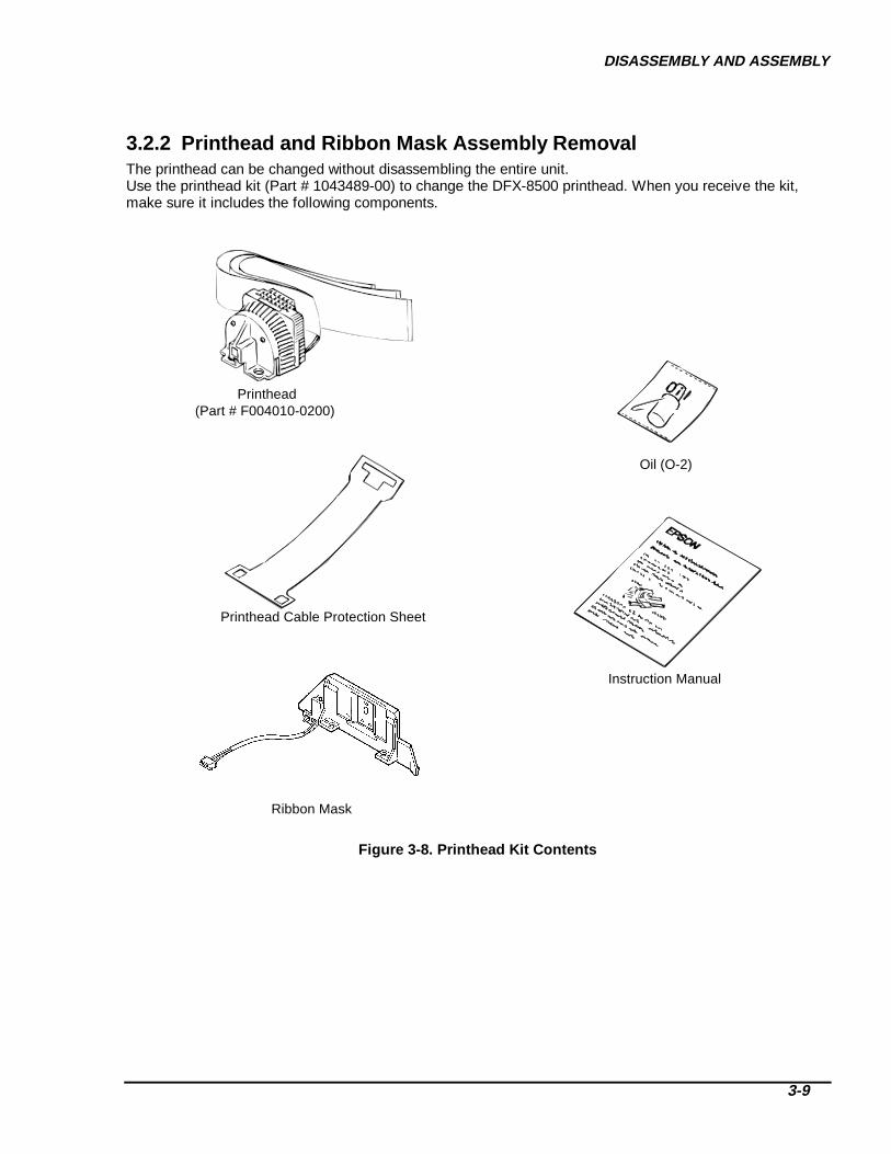
DISASSEMBLY AND ASSEMBLY
3-9
3.2.2 Printhead and Ribbon Mask Assembly RemovalThe printhead can be changed without disassembling the entire unit.Use the printhead kit (Part # 1043489-00) to change the DFX-8500 printhead. When you receive the kit,make sure it includes the following components.
Printhead(Part # F004010-0200)
Oil (O-2)
Printhead Cable Protection Sheet
Instruction Manual
Ribbon Mask
Figure 3-8. Printhead Kit Contents

DFX-8500
3-10
CAUTION
When you remove the connector cover, be careful not to break the tabs.
When you remove the printhead cable holder, be careful not to break the printhead holder latch. Usea slotted screwdriver if necessary.
1. Open the top cover and remove the ribbon cartridge.2. Remove the 2 screws (CBS, M3×8) securing the FPC cover to the bottom plate of the printer
mechanism.3. Disconnect the three printhead cables and a ground cable from the connector junction board on the
bottom plate.Notes:
Grip the cables close to the connector when removing them.Hold the connector so it won’t detach from the board.Pull the cables horizontally; do not pull up.
Screws (CBS, M3×8)
FPC CoverPrinthead Cables
FPC Board
Figure 3-9. Ribbon Cartr idge Removal Figure 3-10. Printhead Cable Removal
4. Unlock the two latches on the printhead cable cover by pressing them toward each other, then removethe cover by sliding it to the right. (See Figure 3-11.)
5. Remove the cable protection sheet.
Figure 3-11. Printhead Cable Co ver Removal

DISASSEMBLY AND ASSEMBLY
3-11
6. Disconnect the narrow FPC cable from the white connector. (See Figure 3-12.)7. Move the carriage to the 90th column (on the scale above the platen). Remove 2 screws (CP (S-P1),
M4×7) securing the printhead, then remove 1 screw (CP (S-P1), M3×6) securing the ground FPC. (SeeFigure 3-12.)
8. Remove the printhead.
P a p e r W i d t h S e n s o rF P C C a b l e
S c r e w ( C P ( S - P 1 ) , M 3 × 6 )
C a r r i a g e
S c r e w s ( C P ( S - P 1 ) , M 4 × 7 )
P r i n t h e a d
Figure 3-12. Printhead Removal
9. Disconnect the paper width sensor cable from the white connector on the ribbon mask. (See Figure 3-13.)
10. Remove the 2 shafts securing the ribbon mask to the carriage using an Allen wrench, then remove theribbon mask. (See Figure 3-13.)
P a p e r W i d t hS e n s o r C o n n e c t o r
R i b b o nM a s k
S h a f t s
C a r r i a g e E n c o d e rS e n s o r C o n n e c t o r
Figure 3-13. Ribbon M ask Removal
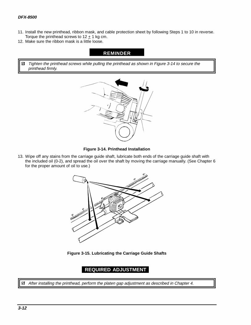
DFX-8500
3-12
11. Install the new printhead, ribbon mask, and cable protection sheet by following Steps 1 to 10 in reverse.Torque the printhead screws to 12 + 1 kg cm.
12. Make sure the ribbon mask is a little loose.
REMINDER
Tighten the printhead screws while pulling the printhead as shown in Figure 3-14 to secure theprinthead firmly.
Figure 3-14. Printhead Installation
13. Wipe off any stains from the carriage guide shaft, lubricate both ends of the carriage guide shaft withthe included oil (0-2), and spread the oil over the shaft by moving the carriage manually. (See Chapter 6for the proper amount of oil to use.)
Figure 3-15. Lubricating the Carriage Guide Shafts
After installing the printhead, perform the platen gap adjustment as described in Chapter 4.
REQUIRED ADJUSTMENT
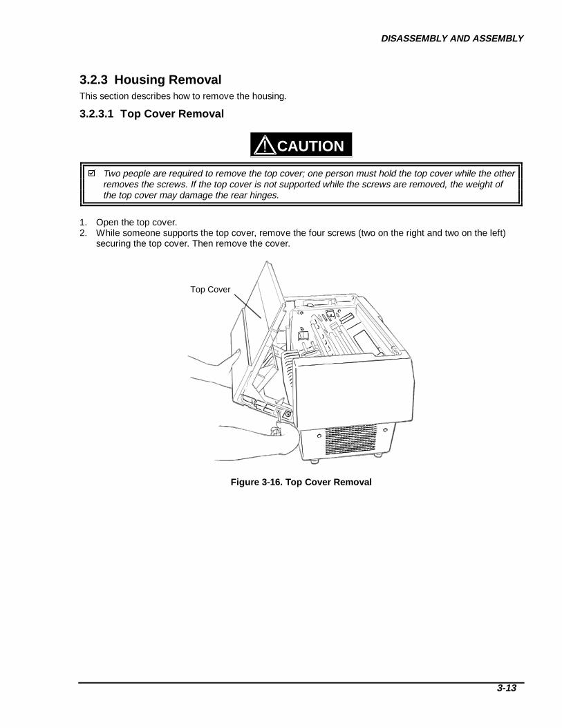
DISASSEMBLY AND ASSEMBLY
3-13
3.2.3 Housing RemovalThis section describes how to remove the housing.
3.2.3.1 Top Cover Removal
CAUTION
Two people are required to remove the top cover; one person must hold the top cover while the otherremoves the screws. If the top cover is not supported while the screws are removed, the weight ofthe top cover may damage the rear hinges.
1. Open the top cover.2. While someone supports the top cover, remove the four screws (two on the right and two on the left)
securing the top cover. Then remove the cover.
Top Cover
Figure 3-16. Top Co ver Removal

DFX-8500
3-14
3.2.3.2 Left, Right, and Front Covers Removal and Fuse Replacement1. Remove 4 screws (CBB, M4×16) securing the left cover, then remove the left cover.2. Remove the right cover the same way.3. Disconnect 4 cables from the main power switch in the right cover. (See Figure 3-18.)
Screws (CBB, M4×16)
Right and Left Covers
Screws (CBB, M4×16)
Screws (CBB, M4×16)
Screws (CBB, M4×16)
Figure 3-17. Left and Right Co ver Removal
ASSEMBLING POINT
When you attach the right side cover, connect the cable from connector CN1 on the C204 power supplyboard unit and the cable from the AC inlet to the main switch in the right cover, as shown below.
Main Switch
Inside Right Cover
AC Inlet Set
C204 Power Supply Board
11 12
24 25
CN
1
Brown cable
Blue cable
Brown cable
Blue cable
Figure 3-18. Cables to the Main Switch

DISASSEMBLY AND ASSEMBLY
3-15
4. After you remove the right side cover, you may replace the C204 power supply board’s input fuse.
WARNING
Make sure the new fuse meets the printer's AC power specifications.
Carriage Motor
CN1
C204 PSB/PSE Board
Ground Cable
(Right Side)
Fuse
Figure 3-19. Fuse Removal
5. Remove 3 screws (CBB, M4×16) securing the left side of the front cover to the lower cover. Thenremove the front cover along the left hinge.
Screw (CBB, M4×16)
Front Cover
Figure 3-20. Front Co ver Removal

DFX-8500
3-16
3.2.3.3 Front Panel Removal1. Remove the left and right covers. (See Section 3.2.3.2)2. Open the top cover and disconnect control panel connector CN5.3. Remove 2 screws (CBB, M4×16) from the control panel, then remove the control panel and control
panel connector cable.
Screws (CBB, M4×16) Front Panel Unit
Figure 3-21. Front Panel Removal

DISASSEMBLY AND ASSEMBLY
3-17
3.2.3.4 Upper Case Removal1. Remove the left and right covers. (See Section 3.2.3.2.)2. Remove the front panel unit. (See Section 3.2.3.3.)3. Remove 8 screws (6 CBB, M4×16 and 2 CBB, M3×10) from the upper case, then remove the upper
case. (See Figure 3-21.)
Screws (CBB, M4×16)
Screws (CBB, M3×10)
Upper Case
Figure 3-22. Upper Case Removal

DFX-8500
3-18
3.2.4 Circuit Board RemovalThis section describes how to remove the circuit boards.
3.2.4.1 Bottom Panel Removal
CAUTION
Spread a thick, soft cloth under the printer before you follow the steps below.
Make sure the parallel interface cable latch is not caught between the lower case and bottom panelwhen you attach the bottom panel..
1. Remove the left and right covers. (See Section 3.2.3.2)2. On the right side of the printer mechanism, remove 1 screw (CBS (O), M4×8) securing the green and
yellow ground cable to the ground plate.
Ground Cable
Screw (CBS (O), M4×8)
C204 PSB/PSEBoard
(Right side)
Bottom PanelAssembly
Figure 3-23. Connector and Ground Cable Removal (r ight side)
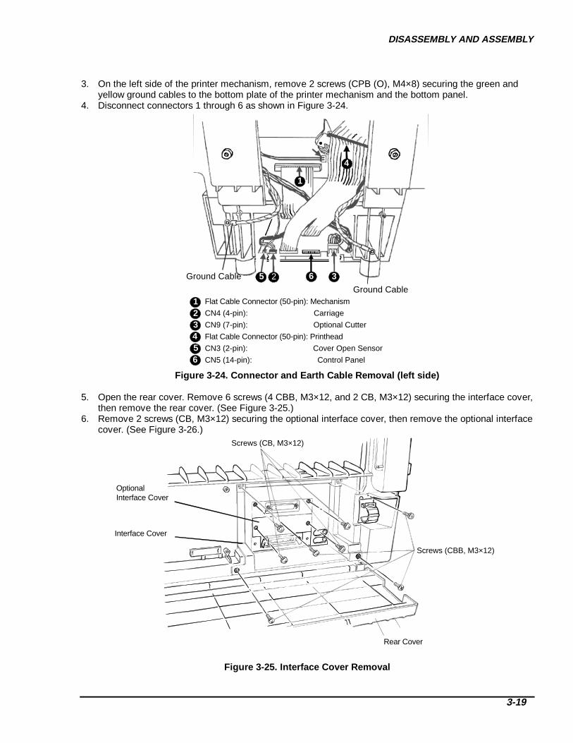
DISASSEMBLY AND ASSEMBLY
3-19
3. On the left side of the printer mechanism, remove 2 screws (CPB (O), M4×8) securing the green and
yellow ground cables to the bottom plate of the printer mechanism and the bottom panel.4. Disconnect connectors 1 through 6 as shown in Figure 3-24.
Ground Cable
Ground Cable
32 6
1
5
4
Flat Cable Connector (50-pin): Mechanism
CN4 (4-pin): Carriage
CN9 (7-pin): Optional Cutter
Flat Cable Connector (50-pin): Printhead
CN3 (2-pin): Cover Open Sensor
CN5 (14-pin): Control Panel
123
654
Figure 3-24. Connector and Earth Cable Removal (left side)
5. Open the rear cover. Remove 6 screws (4 CBB, M3×12, and 2 CB, M3×12) securing the interface cover,then remove the rear cover. (See Figure 3-25.)
6. Remove 2 screws (CB, M3×12) securing the optional interface cover, then remove the optional interfacecover. (See Figure 3-26.)
Screws (CB, M3×12)
Screws (CBB, M3×12)
Rear Cover
Optional Interface Cover
Interface Cover
Figure 3-25. Interf ace Cover Removal
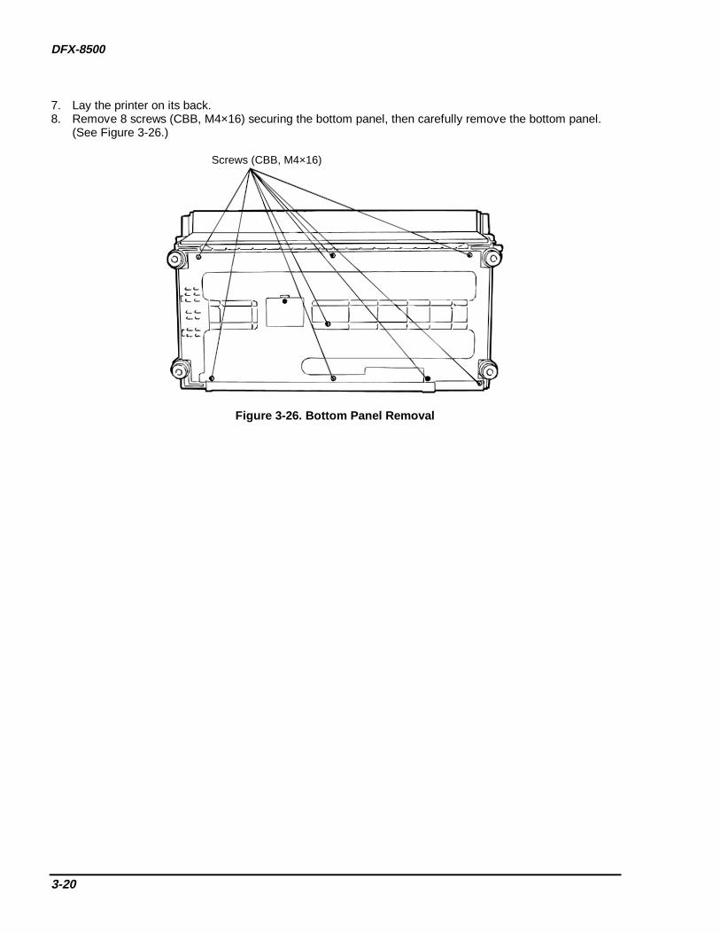
DFX-8500
3-20
7. Lay the printer on its back.8. Remove 8 screws (CBB, M4×16) securing the bottom panel, then carefully remove the bottom panel.
(See Figure 3-26.)
Screws (CBB, M4×16)
Figure 3-26. Bottom Panel Removal

DISASSEMBLY AND ASSEMBLY
3-21
3.2.4.2 Fan and C204 Power Supply Board Removal1. Remove the left and right covers. (See Section 3.2.3.2.)2. Remove the bottom panel. (See Section 3.2.4.1.)3. To remove the fan, disconnect CN5 on the power supply board. Remove 4 screws (CCN, M3x30)
securing the fan, then remove the fan.4. Disconnect CN2, CN3, and CN4 on the power supply board.5. Remove 7 screws (6 CBB, M3×12 and 1 CPN (O), M3×8) securing the C204 power supply board, then
remove the board.
Screws (CBB, M3×12)
CN3
CN5
C204 PSB/PSE Board
CN4
C204 MAIN Board
CN1
AC Power Cable
Screws (CCN, M3×30) Screws (CPN (O), M3×8)
CN2
Figure 3-27. Fan and C204 PSE/PSB Board Removal

DFX-8500
3-22
3.2.4.3 C204 SUB Board Removal1. Remove the left and right covers. (See Section 3.2.3.2.)2. Remove the bottom panel. (See Section 3.2.4.1.)3. Disconnect CN15 and CN16 on the C204 main board.4. Remove 2 screws (1 CBB, M3×8 and 1 CBB, M3×12) securing the C204 SUB board, then remove the
board.
Screw (CBB, M3×12)
Screw (CBB, M3×8)
CN16
CN15
CN15
CN16
C204 Main Board
C204 SUB Board Unit
Figure 3-28. C204 SUB Board Removal
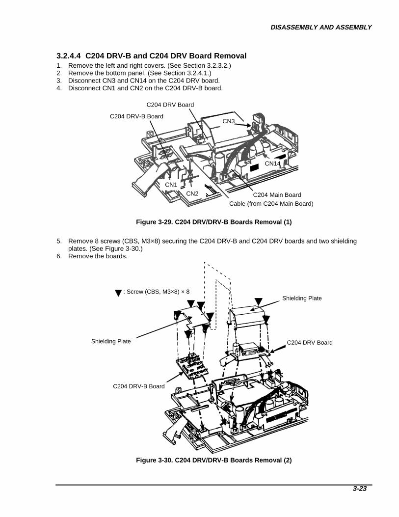
DISASSEMBLY AND ASSEMBLY
3-23
3.2.4.4 C204 DRV-B and C204 DRV Board Removal1. Remove the left and right covers. (See Section 3.2.3.2.)2. Remove the bottom panel. (See Section 3.2.4.1.)3. Disconnect CN3 and CN14 on the C204 DRV board.4. Disconnect CN1 and CN2 on the C204 DRV-B board.
C204 DRV Board
CN3
CN14
C204 DRV-B Board
CN2
CN1
Cable (from C204 Main Board)C204 Main Board
Figure 3-29. C204 DRV/DRV-B Boards Removal (1)
5. Remove 8 screws (CBS, M3×8) securing the C204 DRV-B and C204 DRV boards and two shieldingplates. (See Figure 3-30.)
6. Remove the boards.
Shielding Plate
Shielding Plate
C204 DRV Board
C204 DRV-B Board
: Screw (CBS, M3×8) × 8
Figure 3-30. C204 DRV/DRV-B Boards Removal (2)

DFX-8500
3-24
3.2.4.5 C204 Main Board Removal1. Remove the left and right covers. (See Section 3.2.3.2.)2. Remove the bottom panel. (See Section 3.2.4.1.)3. Remove the C204 SUB board. (See Section 3.2.4.3.)4. Remove the C204 DRV-B and C204 DRV boards. (See Section 3.2.4.4.)5. Disconnect CN6, CN7, CN8, and CN10 on the main board. (See Figures 3-31 through 3-33.)
Harness
CN3
to CN6(7-pin)
to CN7(6-pin)
CN2
C204 Main Board
Figure 3-31. C204 Main Board Removal (1)
CN4
Cable
CN10(8-pin)
C204 Main Board
to CN10(8-pin)
to CN4
Figure 3-32. C204 Main Board Removal (2)
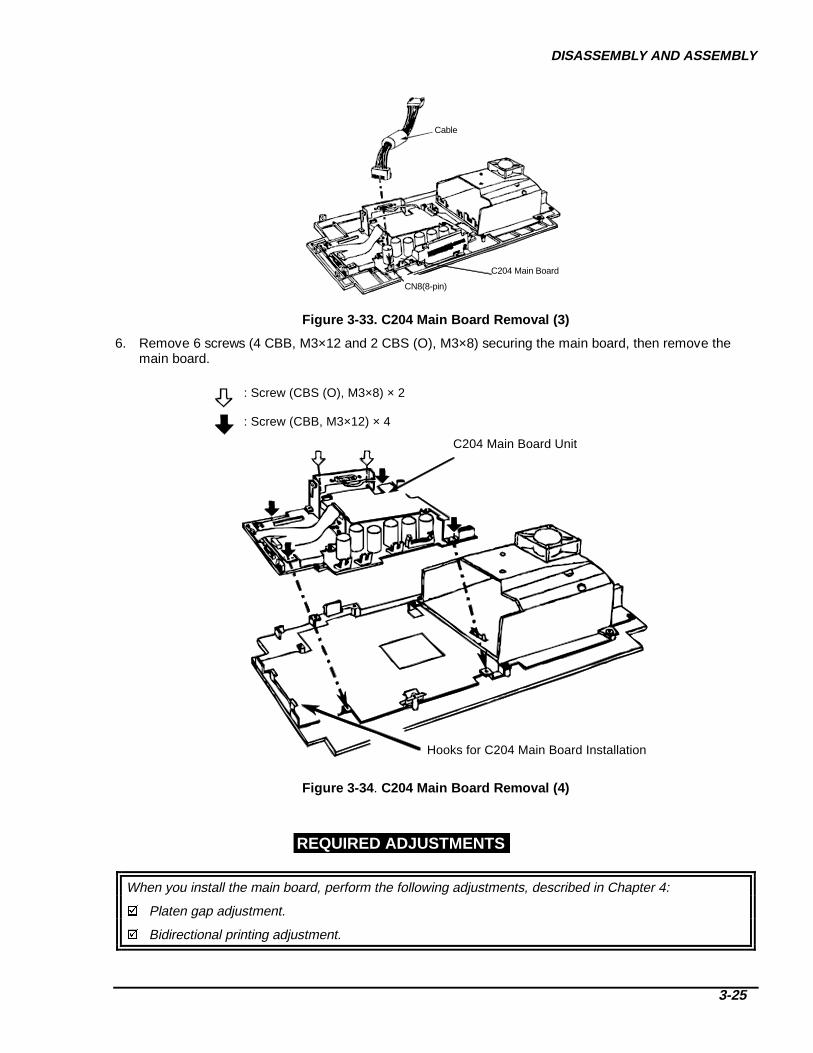
DISASSEMBLY AND ASSEMBLY
3-25
Cable
CN8(8-pin)
C204 Main Board
Figure 3-33. C204 Main Board Removal (3)
6. Remove 6 screws (4 CBB, M3×12 and 2 CBS (O), M3×8) securing the main board, then remove themain board.
: Screw (CBB, M3×12) × 4
: Screw (CBS (O), M3×8) × 2
C204 Main Board Unit
Hooks for C204 Main Board Installation
Figure 3-34 . C204 Main Board Removal (4)
When you install the main board, perform the following adjustments, described in Chapter 4:
Platen gap adjustment.
Bidirectional printing adjustment.
REQUIRED ADJUSTMENTS

DFX-8500
3-26
3.2.4.6 AC Inlet Removal1. Remove the left and right covers. (See Section 3.2.4.2.)2. Remove the bottom panel (See Section 3.2.4.1.)3. Remove the C204 power supply board. (See Section 3.2.4.2.)4. Remove the C204 main board. (See Section 3.2.4.5.)5. Remove 4 screws (3 CBB, M3×8 and 1 CB (O), M4×6) securing the grounding plate to the bottom panel,
then remove the grounding plate. (See Figure 3-35.)
Screws (CBB, M3×8) Bottom PanelGrounding Plate
Screw (CB (O), M4×6)
AC Cable
Figure 3-35. Grounding Plate Removal
6. Remove 2 screws (CFS, M3×10) securing the AC inlet to the grounding plate, then remove the AC inlet.(See Figure 3-36.)
AC Inlet
Grounding Plate
Screw (CFS, M3×10)
Figure 3-36. AC Inlet Removal

DISASSEMBLY AND ASSEMBLY
3-27
3.2.4.7 C204 PNL Board Removal1. Remove the left and right covers. (See Section 3.2.3.2.)2. Remove the front panel. (See Section 3.2.3.3.)3. Disconnect CN1 and CN2 on the C204 PNL board.4. Remove 1 screw (CBB, M4×10) securing the C204 PNL board to the front panel unit, then remove the
C204 PNL board.
Screw (CBB, M4×10)
Front Panel
C204 PNL Board
CN2
CN1
Figure 3-37. C204 PNL Board Removal

DFX-8500
3-28
3.2.5 Interlock Switch and Cover Open Sensor Removal1. Remove the left and right covers. (See Section 3.2.3.2.)2. Remove the front panel (See Section 3.2.3.3.)3. Remove the upper case. (See Section 3.2.3.4.)4. Disconnect the interlock switch cable from the connector junction board. (See Figure 3-41.)5. Disconnect the cover open sensor cable from the main board. (See Figure 3-41.)
Cover Open Sensor
Interlock Switch.
CN3
ConnectorJunction Board
C204 Main Board
Figure 3-38. Disconnecting the Interlock Switch and Co ver Open Sensor Cables
6. Remove 1 screw (CBB, M4×10) securing the interlock switch and cover open sensor to the lower case,then remove the switch and sensor. (See Figure 3-39.)
Interlock Switch and Cover Open Sensor
Screw (CBB, M4×10)
Lower Housing
Figure 3-39. Interlock Switch and Co ver Open Sensor Removal
Interlock Switch
Cover Open Sensor
To CN3 on C204 Main Board
To Connector Junction BoardScrew (CPS, M2.3×18)
Figure 3-40. Interlock Switch and Co ver Open Sensor
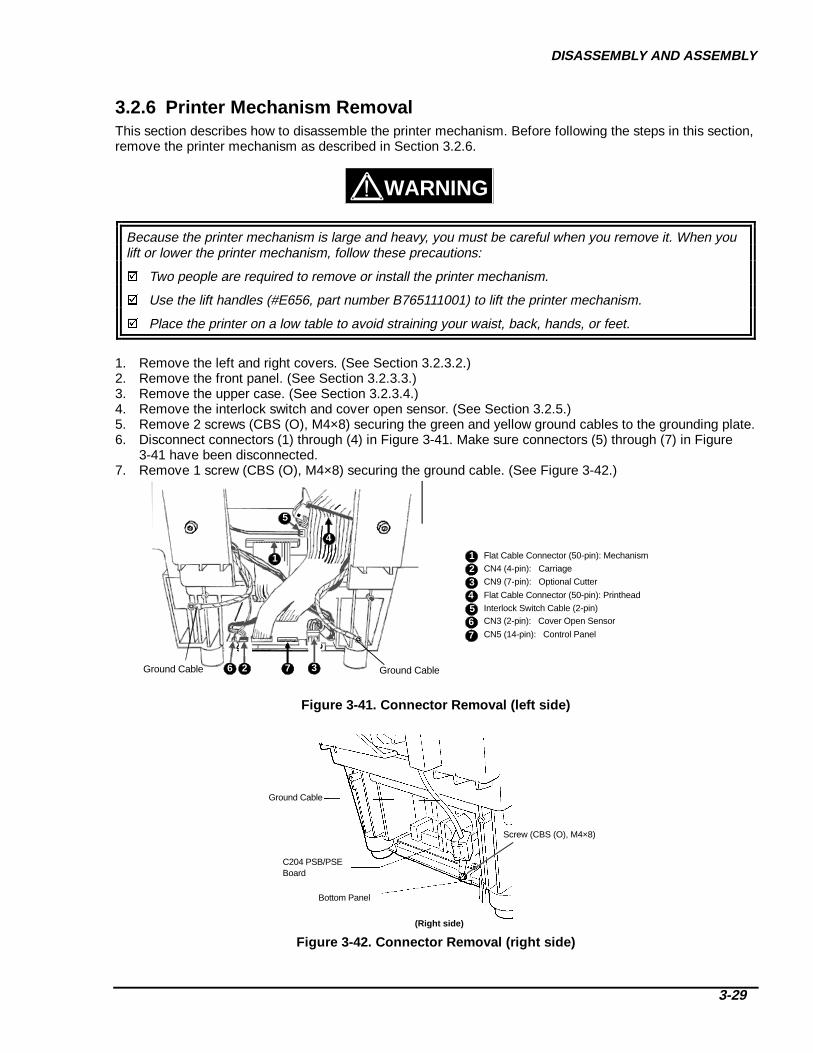
DISASSEMBLY AND ASSEMBLY
3-29
3.2.6 Printer Mechanism RemovalThis section describes how to disassemble the printer mechanism. Before following the steps in this section,remove the printer mechanism as described in Section 3.2.6.
Because the printer mechanism is large and heavy, you must be careful when you remove it. When youlift or lower the printer mechanism, follow these precautions:
Two people are required to remove or install the printer mechanism.
Use the lift handles (#E656, part number B765111001) to lift the printer mechanism.
Place the printer on a low table to avoid straining your waist, back, hands, or feet.
1. Remove the left and right covers. (See Section 3.2.3.2.)2. Remove the front panel. (See Section 3.2.3.3.)3. Remove the upper case. (See Section 3.2.3.4.)4. Remove the interlock switch and cover open sensor. (See Section 3.2.5.)5. Remove 2 screws (CBS (O), M4×8) securing the green and yellow ground cables to the grounding plate.6. Disconnect connectors (1) through (4) in Figure 3-41. Make sure connectors (5) through (7) in Figure
3-41 have been disconnected.7. Remove 1 screw (CBS (O), M4×8) securing the ground cable. (See Figure 3-42.)
Ground Cable Ground Cable3726
1
5
4
3
7
2
654
1 Flat Cable Connector (50-pin): Mechanism
CN4 (4-pin): Carriage
CN9 (7-pin): Optional Cutter
Flat Cable Connector (50-pin): Printhead
Interlock Switch Cable (2-pin)CN3 (2-pin): Cover Open Sensor
CN5 (14-pin): Control Panel
Figure 3-41. Connector Removal (left side)
Ground Cable
Screw (CBS (O), M4×8)
C204 PSB/PSEBoard
(Right side)
Bottom Panel
Figure 3-42. Connector Removal (r ight side)
WARNING
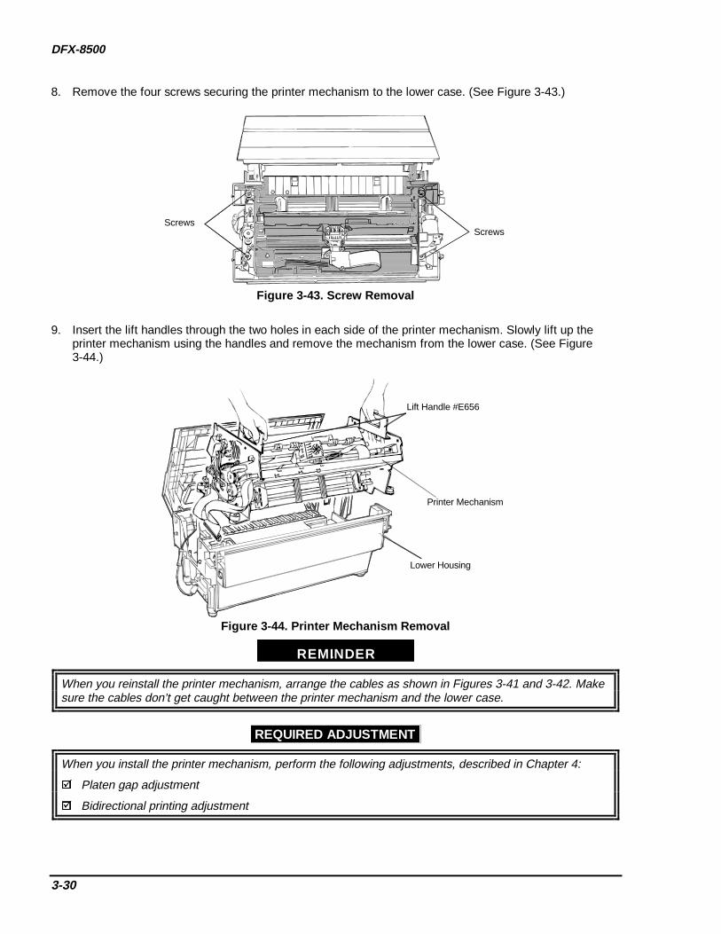
DFX-8500
3-30
8. Remove the four screws securing the printer mechanism to the lower case. (See Figure 3-43.)
ScrewsScrews
Figure 3-43. S crew Removal
9. Insert the lift handles through the two holes in each side of the printer mechanism. Slowly lift up theprinter mechanism using the handles and remove the mechanism from the lower case. (See Figure3-44.)
Lift Handle #E656
Printer Mechanism
Lower Housing
Figure 3-44. Printer Mechanism Removal
REMINDER
When you reinstall the printer mechanism, arrange the cables as shown in Figures 3-41 and 3-42. Makesure the cables don’t get caught between the printer mechanism and the lower case.
REQUIRED ADJUSTMENT
When you install the printer mechanism, perform the following adjustments, described in Chapter 4:
Platen gap adjustment
Bidirectional printing adjustment

DISASSEMBLY AND ASSEMBLY
3-31
3.2.6.1 Fan Removal1. Remove the left and right covers. (See Section 3.2.3.2.)2. Remove the front panel. (See Section 3.2.3.3.)3. Remove the upper case. (See Section 3.2.3.4.)4. Remove the printer mechanism. (See Section 3.2.6.)5. Disconnect the fan connector from the relay connector.6. Remove 1 screw (CP(O), 4×5) securing the fan duct to the left frame and 2 screws (CC, 3×30) securing
the fan and the fan duct to the left frame.7. Remove the fan along with the fan duct.
Screw (CP (O), 4×5)
Screws (CC, 3×30)
Left Frame
Figure 3-45. Fan Removal
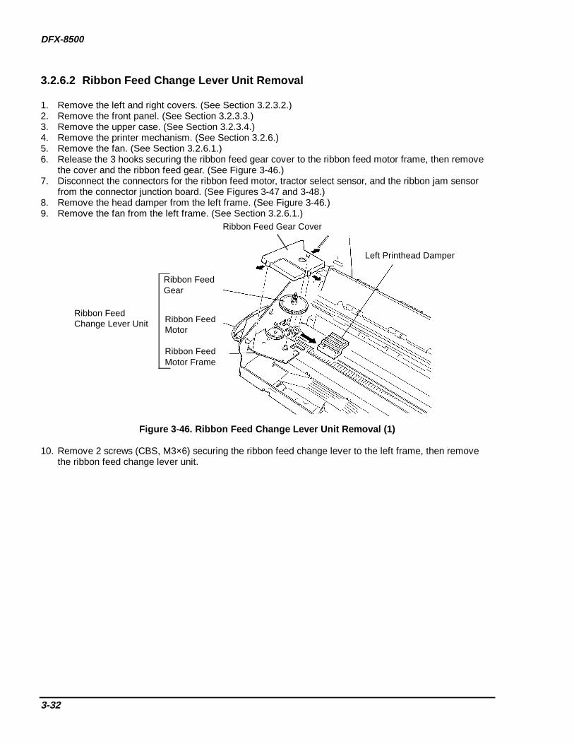
DFX-8500
3-32
3.2.6.2 Ribbon Feed Change Lever Unit Removal
1. Remove the left and right covers. (See Section 3.2.3.2.)2. Remove the front panel. (See Section 3.2.3.3.)3. Remove the upper case. (See Section 3.2.3.4.)4. Remove the printer mechanism. (See Section 3.2.6.)5. Remove the fan. (See Section 3.2.6.1.)6. Release the 3 hooks securing the ribbon feed gear cover to the ribbon feed motor frame, then remove
the cover and the ribbon feed gear. (See Figure 3-46.)7. Disconnect the connectors for the ribbon feed motor, tractor select sensor, and the ribbon jam sensor
from the connector junction board. (See Figures 3-47 and 3-48.)8. Remove the head damper from the left frame. (See Figure 3-46.)9. Remove the fan from the left frame. (See Section 3.2.6.1.)
Left Printhead Damper
Ribbon Feed Gear Cover
Ribbon Feed Gear
Ribbon Feed Motor
Ribbon Feed Motor Frame
Ribbon FeedChange Lever Unit
Figure 3-46. Ribbon Feed Change L ever Unit Removal (1)
10. Remove 2 screws (CBS, M3×6) securing the ribbon feed change lever to the left frame, then removethe ribbon feed change lever unit.

DISASSEMBLY AND ASSEMBLY
3-33
Screw (CBB, M4×10)
Front Panel
C204 PNL Board
CN2
CN1
Figure 3-47. Ribbon Feed Change L ever Unit Removal (2)
To Ribbon Jam Sensor
To Tractor Select SensorTo Ribbon Feed Motor
Connector Junction Board
Figure 3-48. Remov ing Connectors
REMINDER
When you install the ribbon feed change lever unit, make sure you correctly join the tip of the tractorselect lever and the tractor select gear holder. (See Figure 2-12.)

DFX-8500
3-34
3.2.6.3 Tractor Select Lever DisassemblyThis section describes how to disassemble the tractor select lever and how to remove the ribbon feed motorand tractor select sensor.
1. Remove the left and right covers. (See Section 3.2.3.2.)2. Remove the front panel. (See Section 3.2.3.3.)3. Remove the upper case. (See Section 3.2.3.4.)4. Remove the printer mechanism. (See Section 3.2.6.)5. Remove the fan. (See Section 3.2.6.1.)6. Remove the ribbon feed change lever unit. (See Section 3.2.6.2.)7. Remove 2 screws (CP (S-P1), M3×6), 2 leaf springs, and 2 washers securing the ribbon feed motor to
the ribbon feed motor frame, then remove the motor. (See Figure 3-49.)8. Remove 1 e-ring (# 3) securing the upper and lower tractor select levers, then remove the levers. (See
Figure 3-49.)9. Remove 1 e-ring (# 3) securing the tractor select cam, then remove the cam. (See Figure 3-49.)10. Remove 1 screw (CPS (P1), M2×10) securing the tractor select sensor, then remove the sensor. (See
Figure 3-49.)11. Use wire cutters to cut the wire band securing the ribbon feed motor and tractor select sensor cables to
the ribbon feed motor frame.
E - r i n g ( 3 )
W a s h e rL e a f S p r i n g
T r a c t o r S e l e c t T r a n s m i s s i o n G e a r
E - r i n g ( 3 )
T r a c t o r S e l e c tT r a n s m i s s i o n G e a r
R i b b o n F e e d M o t o rF r a m e
R i b b o n F e e d M o t o r
C P ( S - P 1 ) ( M 3 X 6 )
T r a c t o r S e l e c tL e v e r l o w e r
T r a c t o r S e l e c tS e n s o r
T r a c t o r S e l e c tL e v e r S p r i n g
T r a c t o r S e l e c t L e v e r U p p e r
T r a c t o r S e l e c t C a m
C P S ( P 1 ) ( M 2 X 1 0 )
Figure 3-49. T ractor Select Lever Disassembly

DISASSEMBLY AND ASSEMBLY
3-35
REMINDER
During assembly, attach the tractor select levers to the tractor select cam as shown in Figure 3-50.
Ribbon Feed Motor Frame
Tractor Select Cam
Tarctor Select Gear Holder
Ribbon Feed Change Lever(Upper and Lower)
Figure 3-50. T ractor Select Lever Installation
3.2.6.4 Ribbon Jam Sensor Removal1. Remove the left cover. (See Section 3.2.3.2.)2. Disconnect the ribbon jam sensor connector from the connector junction board.3. Remove 1 screw (CP (S-P1), M3×6) securing the sensor to the bracket, then remove the sensor. (See
Figure 3-51.)
Screw (CP (S-P1), M3×6)
Front/Rear Tractor Select Lever
Ribbon Jam Sensor
Figure 3-51. Ribbon Jam Sensor Removal

DFX-8500
3-36
3.2.6.5 Connector Junction Board and FPC Board Removal
This section describes how to remove the connector junction board and FPC board.
1. Remove the left cover. (See Section 3.2.3.2.)2. Disconnect all the cables from the connector junction board. Remove 2 screws (CP (S-P1), M3×6)
securing the connector junction board to the printer mechanism, then remove the connector junctionboard. (See Figure 3-52.)
3. Remove the tractor select lever. (See Section 3.2.6.3.)4. Disconnect the carriage encoder sensor connector from the FPC board.5. Remove 2 screws (CBS, M3×8) securing the FPC cover, then remove the cover. (See Figure 3-10.)6. Remove 1 screw (CPS (P-1), M3×6) securing the FPC board to the printer mechanism, then remove the
FPC board. (See Figure 3-52.)
C o n n e c t o r J u n c t i o n B o a r d
F P C B o a r d
C a r r i a g e E n c o d e rS e n s o r C o n n e c t o r
S c r e w s ( C P S ( S P - 1 ) , M 3 × 6 )
S c r e w ( C P S ( P 1 ) , M 3 × 6 )
Figure 3-52. Connector Junction Board and FPC Board Removal
REMINDER
When you reconnect cables to the connector junction board, make sure the connectors have the samecolor and number of pins as the corresponding cable.

DISASSEMBLY AND ASSEMBLY
3-37
3.2.6.6 Platen Gap (PG) Sensor and PG Motor Removal
CAUTION
Be careful not to bend the PG motor encoder plate when removing or installing the PG sensor.
1. Remove the left cover. (See Section 3.2.3.2.)2. Remove the connector junction board. (See Section 3.2.6.5.)3. Remove 1 screw (CBS, 3×6) securing the PG sensor and the surrounding unit to the left frame, then
remove the sensor toward the front. (See Figure 3-53.)4. Remove 1 screw securing the PG sensor to the surrounding unit, then remove the sensor.5. Remove 2 screws (CP (S-P1), M3×6) securing the PG motor, then remove the motor.
Encoder Plate
Platen Gap MotorPinion Gear
Platen Gap Sensor
Screw (CPS (P), M3×6)
Platen Gap Motor
Screws (CP (S-P1), M3×6)
Figure 3-53. PG Sensor and PG Motor Removal
REMINDER
When you install the PG motor, make sure the distance between the PG motor and PG motortransmission gear is between 0.002 and 0.006 inch (0.05 and 0.15 mm).
When you install the PG sensor unit, align the c-shaped cutout on the unit with the lower shaftsecuring the PG motor to the frame.
When you install the PG sensor or PG motor, perform the platen gap adjustment, as described inChapter 4.
REQUIRED ADJUSTMENT
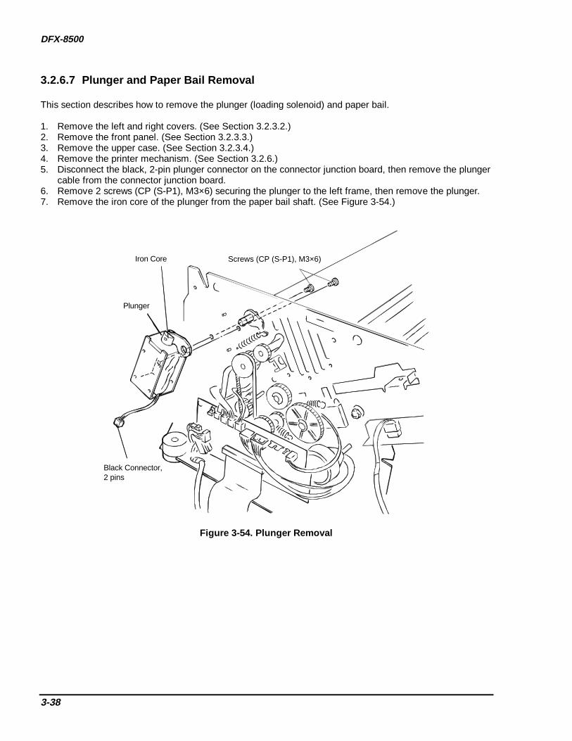
DFX-8500
3-38
3.2.6.7 Plunger and Paper Bail Removal
This section describes how to remove the plunger (loading solenoid) and paper bail.
1. Remove the left and right covers. (See Section 3.2.3.2.)2. Remove the front panel. (See Section 3.2.3.3.)3. Remove the upper case. (See Section 3.2.3.4.)4. Remove the printer mechanism. (See Section 3.2.6.)5. Disconnect the black, 2-pin plunger connector on the connector junction board, then remove the plunger
cable from the connector junction board.6. Remove 2 screws (CP (S-P1), M3×6) securing the plunger to the left frame, then remove the plunger.7. Remove the iron core of the plunger from the paper bail shaft. (See Figure 3-54.)
Plunger
Iron Core Screws (CP (S-P1), M3×6)
Black Connector,2 pins
Figure 3-54. Plunger Removal
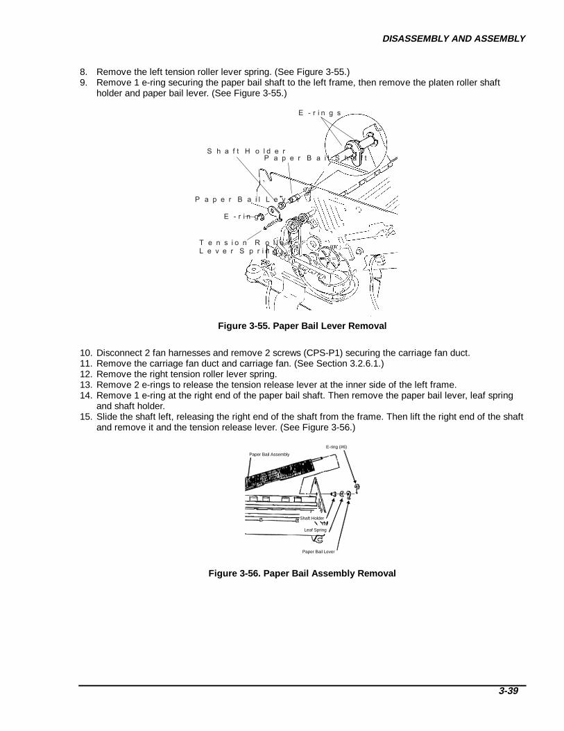
DISASSEMBLY AND ASSEMBLY
3-39
8. Remove the left tension roller lever spring. (See Figure 3-55.)9. Remove 1 e-ring securing the paper bail shaft to the left frame, then remove the platen roller shaft
holder and paper bail lever. (See Figure 3-55.)
E - r i n g s
S h a f t H o l d e rP a p e r B a i l S h a f t
P a p e r B a i l L e v e r
E - r i n g
T e n s i o n R o l l e r L e v e r S p r i n g
Figure 3-55. Paper Bail L ever Removal
10. Disconnect 2 fan harnesses and remove 2 screws (CPS-P1) securing the carriage fan duct.11. Remove the carriage fan duct and carriage fan. (See Section 3.2.6.1.)12. Remove the right tension roller lever spring.13. Remove 2 e-rings to release the tension release lever at the inner side of the left frame.14. Remove 1 e-ring at the right end of the paper bail shaft. Then remove the paper bail lever, leaf spring
and shaft holder.15. Slide the shaft left, releasing the right end of the shaft from the frame. Then lift the right end of the shaft
and remove it and the tension release lever. (See Figure 3-56.)
E-ring (#6)
Paper Bail Assembly
Paper Bail Lever
Leaf Spring
Shaft Holder
Figure 3-56. Paper Bail A ssembly Removal

DFX-8500
3-40
3.2.6.8 Upper Paper Guide and Top PE Sensor Removal
1. Remove the left and right covers. (See Section 3.2.3.2.)2. Remove the front panel. (See Section 3.2.3.3.)3. Remove the upper case. (See Section 3.2.3.4.)4. Remove the printer mechanism. (See Section 3.2.6.)5. Remove the plunger and paper bail. (See Section 3.2.6.7)6. Disconnect the top PE sensor connector (red, 3 pins) from the connector junction board. (See Figure
3-57.)
Connector Junction Board
Top Paper EndSensor Connector
Left Side Frame
Figure 3-57. Top PE Sensor Connector Removal
7. Remove 2 screws (CBS, M4×6) securing the upper paper guide to both frames, then remove the upperpaper guide. (See Figure 3-58.)
8. Remove 2 screws (CPS (SP), M3×8) securing the top PE sensor to the upper paper guide, then removethe sensor. (See Figure 3-58.)
Top Paper End Sensor Upper Paper Guide
Screw (CBS, M4×6) Screw (CPS (SP), M4×8) Screw (CBS, M4×6)
Figure 3-58. Upper Paper Guide and Top PE Sensor Removal
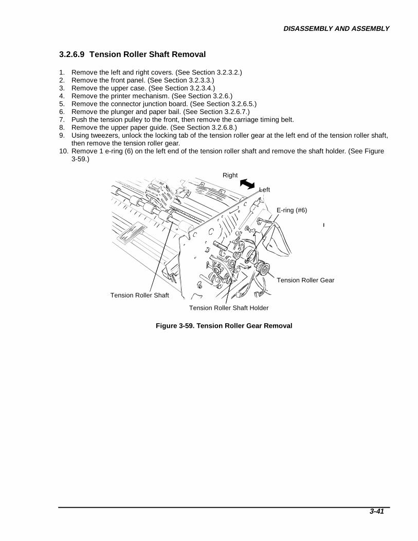
DISASSEMBLY AND ASSEMBLY
3-41
3.2.6.9 Tension Roller Shaft Removal
1. Remove the left and right covers. (See Section 3.2.3.2.)2. Remove the front panel. (See Section 3.2.3.3.)3. Remove the upper case. (See Section 3.2.3.4.)4. Remove the printer mechanism. (See Section 3.2.6.)5. Remove the connector junction board. (See Section 3.2.6.5.)6. Remove the plunger and paper bail. (See Section 3.2.6.7.)7. Push the tension pulley to the front, then remove the carriage timing belt.8. Remove the upper paper guide. (See Section 3.2.6.8.)9. Using tweezers, unlock the locking tab of the tension roller gear at the left end of the tension roller shaft,
then remove the tension roller gear.10. Remove 1 e-ring (6) on the left end of the tension roller shaft and remove the shaft holder. (See Figure
3-59.)
E-ring (#6)
Tension Roller Gear
Tension Roller Shaft Holder
Tension Roller Shaft
Left
Right
Figure 3-59. Tension Roller G ear Removal

DFX-8500
3-42
11. Remove the carriage motor fan. (See Section 3.2.6.19.)12. Remove 1 e-ring (6) from the right end of the tension roller shaft, then remove the tension roller shaft
holder, 1 leaf spring and 1 washer. (See Figure 3-60.)13. Pull the tension roller shaft out of the right frame and remove it. (See Figure 3-61.)
Tension Roller Shaft Tension Roller Shaft Holder
Leaf Spring
E-ring
Carriage Motor
Washer
Figure 3-60. Shaft Holder Removal
Tension Roller Shaft
Front
Left
Figure 3-61. Tension Roller Shaft Removal

DISASSEMBLY AND ASSEMBLY
3-43
3.2.6.10 Platen Removal1. Remove the left and right covers. (See Section 3.2.3.2.)2. Remove the front panel. (See Section 3.2.3.3.)3. Remove the upper case. (See Section 3.2.3.4.)4. Remove the printer mechanism. (See Section 3.2.6.)5. Remove the plunger and paper bail. (See Section 3.2.6.7.)6. Remove the upper paper guide. (See Section 3.2.6.8.)7. Remove the four hex screws securing the platen to the platen holders. (See Figure 3-62.)8. Remove the platen and the lower paper guide. (See Figure 3-62.)9. Slide the 3 parts of the lower paper guide slide out of the corresponding notches in the platen, then
remove them from the platen.Hex Screws
Platen
Platen Holder (Left) Platen Holder (Right)Lower Paper Guide
Rear
Figure 3-62. Platen Removal
Platen
Platen Holder Positioning Tab
0.03 mmThickness Gauge
Front
Rear
Thickness gauge should not fit here
Figure 3-63. Platen Positioning
REMINDER
Attach the 3 parts of the lower paper guide to the platen from right to left.
There must be less than 0.0012 in. (0.03 mm) between the platen and the positioning tabs. (SeeFigure 3-63.)
REQUIRED ADJUSTMENT
After installing the platen, perform the following adjustments, described in Chapter 4:
Carriage guide shaft parallelism adjustment
Platen angle (right angle) adjustment
Platen gap adjustment

DFX-8500
3-44
3.2.6.11 Paper Jam Sensor Removal
1. Remove the left and right covers. (See Section 3.2.3.2.)2. Remove the front panel. (See Section 3.2.3.3.)3. Remove the upper case. (See Section 3.2.3.4.)4. Remove the printer mechanism. (See Section 3.2.6.)5. Remove the plunger and paper bail. (See Section 3.2.6.7.)6. Remove the upper paper guide and top PE sensor. (See Section 3.2.6.8.)7. Remove the platen. (See Section 3.2.6.10.)8. Remove 1 screw (CPN (SP), M4×8) securing the left part of the lower paper guide to the platen. (See
Figure 3-64.)9. Remove the left part of the lower paper guide from the platen. (See Figure 3-64.)
Lower Paper Guide
Screw (CPN (SP), M4×8)
Platen
Right
Left
Figure 3-64. Lower Paper Guide Left Part Removal
10. Unhook the paper jam sensor cover, then remove it. (See Figure 3-65.)11. Remove the paper jam sensor. (See Figure 3-65.)
Paper Jam Sensor
Paper Jam Sensor Cover
Lower Paper Guide (Left)
Figure 3-65. Paper Jam Sensor Removal
REMINDER
Make sure the paper jam sensor is oriented correctly when you reattach it.

DISASSEMBLY AND ASSEMBLY
3-45
3.2.6.12 Pull Tractor Sensor Removal
1. Remove the left and right covers. (See Section 3.2.3.2.)2. Remove the front panel. (See Section 3.2.3.3.)3. Remove the upper case. (See Section 3.2.3.4.)4. Remove the printer mechanism. (See Section 3.2.6.)5. Remove the plunger and paper bail. (See Section 3.2.6.7.)6. Remove the upper paper guide. (See Section 3.2.6.8)7. Disconnect the pull tractor sensor connector (red, 2 pins) from the connector junction board.8. Remove 1 screw (CP (S), M2×14) securing the pull tractor sensor to the left side frame, then remove
the sensor. (See Figure 3-66.)
Screw (CP (S), M2×14)
Washer
Pull Tractor Sensor
Right Platen Holder
Hexagon Nut
Figure 3-66. Pull T ractor Sensor Removal

DFX-8500
3-46
3.2.6.13 Paper Width Sensor Removal
1. Open the top cover.2. Disconnect the paper width sensor connector. (See Figure 3-67.)3. Remove 1 screw (CP (S-P1), M2.5×6) securing the paper width sensor to the ribbon mask holder, then
remove the sensor. (See Figure 3-67.)
Screw(CP (S-P1), M2.5×6)
Paper Width Sensor
Paper Width Sensor Connector
Figure 3-67. Paper Width Sensor Removal

DISASSEMBLY AND ASSEMBLY
3-47
3.2.6.14 Platen Gap Home Sensor Removal
1. Remove the left and right covers. (See Section 3.2.3.2.)2. Remove the front panel. (See Section 3.2.3.3.)3. Remove the upper case. (See Section 3.2.3.4.)4. Remove the interlock switch and cover open sensor. (See Section 3.2.5.)5. Remove the printer mechanism (See Section 3.2.6.)6. Remove the fan. (See Section 3.2.6.1.)7. Remove the ribbon feed change lever. (See Section 3.2.6.2.)8. Remove the tractor select lever. (See Section 3.2.6.3.)9. Remove 1 e-ring securing the carriage guide shaft gear to the rear carriage guide shaft. (See Figure
3-68.)
Rear Carriage Guide Shaft
E-ring
Carriage Guide ShaftGear
Figure 3-68. Carriage Guide Shaft G ear Removal
10. Disconnect the platen gap home sensor connector (white, 2 pins) from the connector junction board.11. Detach the hook securing the platen gap home sensor, then remove the sensor. (See Figure 3-69.)
Platen Gap Home Sensor
Platen Gap Motor
Figure 3-69. PG Home Sensor Removal

DFX-8500
3-48
REMINDER
When installing the carriage guide shaft gear, align the rib on the gear with the platen gap adjustmenttransmission gear, then rotate the carriage guide shaft gear counterclockwise for 10 mm. (SeeFigure 3-70.)
Frame Left
Carriage Guide Shaft Gear
Platen Gap Transmission Gear
Flat Part of Rear Carriage Guide Shaft
Advance 10 mm
Stopper
Figure 3-70. Carriage Guide Shaft G ear Alignment
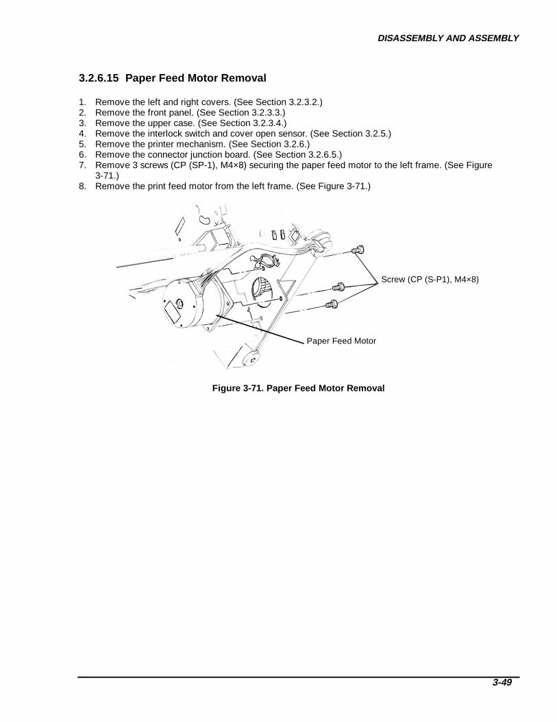
DISASSEMBLY AND ASSEMBLY
3-49
3.2.6.15 Paper Feed Motor Removal
1. Remove the left and right covers. (See Section 3.2.3.2.)2. Remove the front panel. (See Section 3.2.3.3.)3. Remove the upper case. (See Section 3.2.3.4.)4. Remove the interlock switch and cover open sensor. (See Section 3.2.5.)5. Remove the printer mechanism. (See Section 3.2.6.)6. Remove the connector junction board. (See Section 3.2.6.5.)7. Remove 3 screws (CP (SP-1), M4×8) securing the paper feed motor to the left frame. (See Figure
3-71.)8. Remove the print feed motor from the left frame. (See Figure 3-71.)
Screw (CP (S-P1), M4×8)
Paper Feed Motor
Figure 3-71. Paper Feed Motor Removal
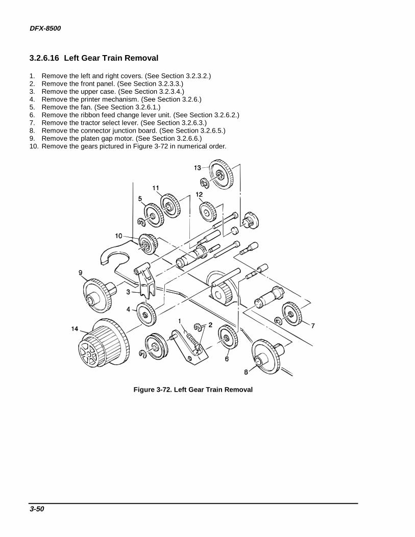
DFX-8500
3-50
3.2.6.16 Left Gear Train Removal
1. Remove the left and right covers. (See Section 3.2.3.2.)2. Remove the front panel. (See Section 3.2.3.3.)3. Remove the upper case. (See Section 3.2.3.4.)4. Remove the printer mechanism. (See Section 3.2.6.)5. Remove the fan. (See Section 3.2.6.1.)6. Remove the ribbon feed change lever unit. (See Section 3.2.6.2.)7. Remove the tractor select lever. (See Section 3.2.6.3.)8. Remove the connector junction board. (See Section 3.2.6.5.)9. Remove the platen gap motor. (See Section 3.2.6.6.)10. Remove the gears pictured in Figure 3-72 in numerical order.
Figure 3-72. Left G ear Train Removal

DISASSEMBLY AND ASSEMBLY
3-51
3.2.6.17 Front Tractor Removal
1. Remove the left and right covers. (See Section 3.2.3.2.)2. Remove the front panel. (See Section 3.2.3.3.)3. Remove the upper case. (See Section 3.2.3.4.)4. Remove the printer mechanism. (See Section 3.2.6.)5. Remove the connector junction board. (See Section 3.2.6.5.)6. Lay the printer mechanism on its back.7. Remove 1 screw securing the tractor wire holder to the left side frame, then remove the left tractor wire
holder. (See Figure 3-73.)8. Loosen the flange nut securing the front tractor to the left frame, then remove the tractor transmission
gear. (See Figure 3-74.)9. Remove the flange nut on the right side of the front tractor, then remove the right tractor wire holder.
(See Figure 3-73.)10. Remove 1 e-ring (6) securing the rear shaft of the front tractor to the left frame, then remove the shaft
holder, leaf spring, and washer. (See Figure 3-74.)11. Pull the front tractor to the left to release the right end of the shaft from the frame, then remove the front
tractor. (See Figure 3-74.)
Screw (CBS, M4×8)
Tractor Wire Holder (L)
CarriageMotor
Nut
TractorWire Spring
Tractor Wire Holder (R)
<Left> <Right>
Figure 3-73. T ractor Wire Removal
Shaft HolderE-ring (#6) Front Tractor
Shaft HolderLeaf Spring
Washer
E-ring (#6)
Tractor TransmissionGear
Flange Nut
Flange Nut
Figure 3-74. Front T ractor Removal
REMINDER
When you install the front tractor, perform the tractor wire spring adjustment described in Chapter 4..
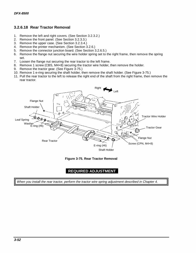
DFX-8500
3-52
3.2.6.18 Rear Tractor Removal
1. Remove the left and right covers. (See Section 3.2.3.2.)2. Remove the front panel. (See Section 3.2.3.3.)3. Remove the upper case. (See Section 3.2.3.4.)4. Remove the printer mechanism. (See Section 3.2.6.)5. Remove the connector junction board. (See Section 3.2.6.5.)6. Remove the flange nut securing the wire holder spring set to the right frame, then remove the spring
set.7. Loosen the flange nut securing the rear tractor to the left frame.8. Remove 1 screw (CBS, M4×8) securing the tractor wire holder, then remove the holder.9. Remove the tractor gear. (See Figure 3-75.)10. Remove 1 e-ring securing the shaft holder, then remove the shaft holder. (See Figure 3-75.)11. Pull the rear tractor to the left to release the right end of the shaft from the right frame, then remove the
rear tractor.
Shaft Holder
E-ring (#6)
Rear Tractor
WasherLeaf Spring
Flange Nut
Shaft Holder
E-ring (#6)
Flange Nut
LeftRight
Tractor Wire Holder
Screw (CPN, M4×8)
Tractor Gear
Figure 3-75. Rear Tractor Removal
When you install the rear tractor, perform the tractor wire spring adjustment described in Chapter 4.
REQUIRED ADJUSTMENT

DISASSEMBLY AND ASSEMBLY
3-53
3.2.6.19 Carriage Motor Fan Removal
1. Remove the left and right covers. (See Section 3.2.3.2.)2. Remove the front panel. (See Section 3.2.3.3.)3. Remove the upper case. (See Section 3.2.3.4.)4. Remove the printer mechanism. (See Section 3.2.6.)5. Disconnect the motor cable from the relay connector. (See Figure 3-76.)6. Remove 2 screws securing the fan, then remove the fan. (See Figure 3-76.)
Screws
Right Frame
Carriage Motor Fan
Figure 3-76. Carriage Motor Fan Removal

DFX-8500
3-54
3.2.6.20 Carriage Motor Removal
1. Remove the left and right covers. (See Section 3.2.3.2.)2. Remove the front panel. (See Section 3.2.3.3.)3. Remove the upper case. (See Section 3.2.3.4.)4. Remove the printer mechanism. (See Section 3.2.6.)5. Remove the carriage motor fan. (See Section 3.2.6.19.)6. Disconnect the red and black cables from the terminals on the carriage motor. There are two cables for
each terminal.7. Remove 3 screws (CP (S), M4×10) securing the carriage motor to the right frame, then remove the
motor. (See Figure 3-77.)
Screw (CP (S), M4×10)
Carriage Motor
Figure 3-77. Carriage Motor Removal
REQUIRED ADJUSTMENT
When you install the CR motor, perform the carriage timing belt tension and platen gap adjustments, asdescribed in Chapter 4.
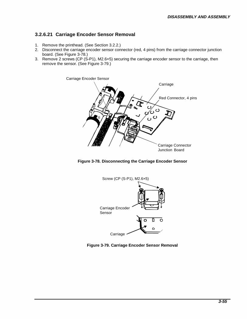
DISASSEMBLY AND ASSEMBLY
3-55
3.2.6.21 Carriage Encoder Sensor Removal
1. Remove the printhead. (See Section 3.2.2.)2. Disconnect the carriage encoder sensor connector (red, 4 pins) from the carriage connector junction
board. (See Figure 3-78.)3. Remove 2 screws (CP (S-P1), M2.6×5) securing the carriage encoder sensor to the carriage, then
remove the sensor. (See Figure 3-79.)
Carriage
Red Connector, 4 pins
Carriage Encoder Sensor
Carriage Connector Junction Board
Figure 3-78. Disconnecting the Carriage Encoder Sensor
Carriage
Carriage EncoderSensor
Screw (CP (S-P1), M2.6×5)
Figure 3-79. Carriage Encoder Sensor Removal

DFX-8500
3-56
3.2.6.22 Carriage Mechanism Disassembly
This section describes how to disassemble the carriage mechanism, including the carriage, carriage timingbelt, and front and rear carriage guide shafts.
1. Remove the left and right covers. (See Section 3.2.3.2.)2. Remove the front panel. (See Section 3.2.3.3.)3. Remove the upper case. (See Section 3.2.3.4.)4. Remove the printer mechanism. (See Section 3.2.6.)5. Remove the carriage motor fan. (See Section 3.2.6.19.)6. Remove the carriage motor. (See Section 3.2.6.20.)7. Remove the belt pulley from the belt pulley holder. (See Figure 3-80.)
Left Frame
Belt Pulley
Belt Pulley Holder
Figure 3-80. Belt Pulley Removal
8. Unhook the spring securing the encoder belt to the right frame. (See Figure 2-5.)9. Loosen the two flange nuts securing the front carriage guide shaft to the frame. (See Figure 3-81.)
Flange Nut
Flange Nut
Front Carriage Guide Shaft
Figure 3-81. Front Carriage Guide Shaft Removal

DISASSEMBLY AND ASSEMBLY
3-57
10. Slide the carriage to the left side. Pull the front carriage guide shaft through the hole in the right frameand remove it. (See Figure 3-81.)
11. On the left frame, remove 1 e-ring (6) securing the carriage guide shaft gear to the rear carriage guideshaft.
12. Remove the carriage guide shaft gear and paper thickness sensor holder. (See Figure 3-82.)13. Unhook the spring securing the paper thickness sensor, then remove the sensor. (See Figure 3-82.)
Paper Thickness Sensor
Carriage Guide Shaft Gear
E-ring (#6)
Screws (CP (P), M3×6)Platen Gap Motor
Rear Carriage Guide Shaft
Figure 3-82. Rear Carriage Guide Shaft Removal
14. Remove the platen gap motor. (See Section 3.2.6.6.)15. Remove the rubber carriage damper from inside the right frame, then remove 3 screws (CBS, M4×8)
securing the carriage motor holder to the right side frame. (See Figure 3-83.)16. Remove the guide shaft holding spring and 1 e-ring securing the right guide shaft holder lever, then
remove the right guide shaft holder lever. (See Figure 3-83.)17. Remove 2 screws (CP (S-P1), M4×6) securing the parallelism adjustment lever, then remove the lever.
(See Figure 3-83.)18. Remove the rear carriage guide shaft and the carriage base from the right frame. (See Figure 3-83.)
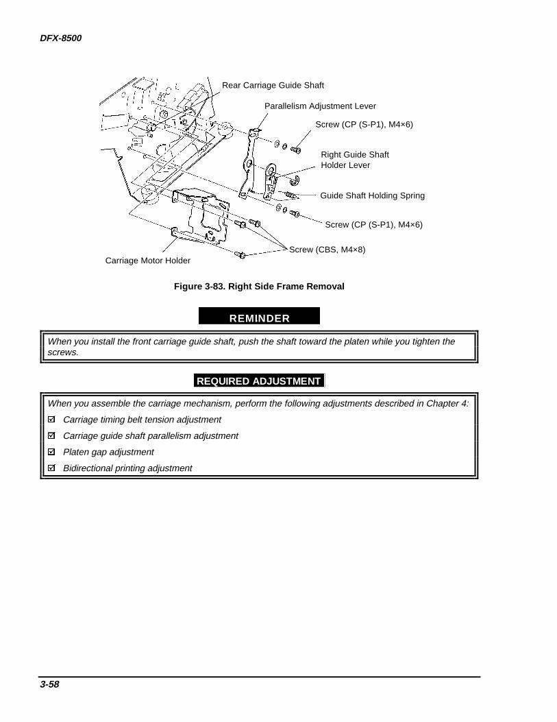
DFX-8500
3-58
Rear Carriage Guide Shaft
Parallelism Adjustment Lever
Screw (CP (S-P1), M4×6)
Right Guide ShaftHolder Lever
Guide Shaft Holding Spring
Screw (CP (S-P1), M4×6)
Screw (CBS, M4×8)Carriage Motor Holder
Figure 3-83. Right Side F rame Removal
REMINDER
When you install the front carriage guide shaft, push the shaft toward the platen while you tighten thescrews.
REQUIRED ADJUSTMENT
When you assemble the carriage mechanism, perform the following adjustments described in Chapter 4:
Carriage timing belt tension adjustment
Carriage guide shaft parallelism adjustment
Platen gap adjustment
Bidirectional printing adjustment

DISASSEMBLY AND ASSEMBLY
3-59
3.2.6.23 Paper Guide Support Plate Removal
1. Remove the left and right covers. (See Section 3.2.3.2.)2. Remove the front panel. (See Section 3.2.3.3.)3. Remove the upper case. (See Section 3.2.3.4.)4. Remove the printer mechanism. (See Section 3.2.6.)5. Remove the carriage motor fan. (See Section 3.2.6.19.)6. Remove the carriage motor. (See Section 3.2.6.20.)7. Disassemble the carriage mechanism. (See Section 3.2.6.22.)8. Remove the paper guide support plate. (See the exploded diagram in the Appendix.)
ADJUSTMENT REQUIRED
When you install the paper guide support plate, perform the following adjustments described inChapter 4:
Carriage timing belt tension adjustment
Carriage guide shaft parallelism adjustment
Platen gap adjustment
Bidirectional printing adjustment
3.2.6.24 Platen Roller Removal
1. Remove the left and right covers. (See Section 3.2.3.2.)2. Remove the front panel. (See Section 3.2.3.3.)3. Remove the upper case. (See Section 3.2.3.4.)4. Remove the printer mechanism. (See Section 3.2.6.)5. Remove the plunger and paper bail. (See Section 3.2.6.7.)6. Remove the upper paper guide. (See Section 3.2.6.8.)7. Remove the platen. (See 3.2.6.10)8. Remove the carriage motor. (See Section 3.2.6.20.)9. Remove the left gear train. (See Section 3.2.6.16.)10. Remove the platen roller (See the exploded diagram in the Appendix.)
ADJUSTMENT REQUIRED
When you install the platen roller, perform the following adjustments described in Chapter 4:
Carriage timing belt tension adjustment
Carriage guide shaft parallelism adjustment
Platen gap adjustment
Bidirectional printing adjustment

DFX-8500
3-60
CHAPTER 4ADJUSTMENT
4.1 OVERVIEW ___________________________________________________________________1
4.2 Platen Gap Motor Placement Adjustment ____________________________________________1
4.3 Carriage Timing Belt Tension Adjustment ___________________________________________2
4.4 Tractor Wire Spring Tension Adjustment ____________________________________________3
4.5 Pull Tractor Sensor Position Adjustment_____________________________________________4
4.6 Carriage Guide Shaft Parallelism Adjustment ________________________________________5
4.7 Platen Angle Adjustment__________________________________________________________9
4.8 Platen Gap Adjustment __________________________________________________________11Resetting the Platen Gap Values_______________________________________________________________ 12Measuring the Platen Gap Values______________________________________________________________ 13
4.9 Bi-directional Printing Adjustment ________________________________________________15

ADJUSTMENT
4-1
4.1 OVERVIEWThis chapter describes the printer mechanism adjustments required after any part is replaced or repaired.Perform the appropriate adjustments before assembling the printer.
4.2 PLATEN GAP MOTOR PLACEMENT ADJUSTMENTIn this adjustment, the platen gap motor pinion gear must mesh smoothly with the platen gap transmissiongear. If the pinion gear is poorly aligned or the two gears are too tight, the printer operation will be noisy orthe character density will be incorrect.
If the platen gap motor placement is too tight, the platen gap motor won’t rotate smoothly and the panel willflash “E3.”
1. Loosen 2 screws securing the platen gap motor to the left frame. (See Figure 4-1.)2. Make sure the platen gap motor pinion gear is properly aligned with the platen gap transmission gear.
The space between them should be 0.002 to 0.01 inches (0.05 to 0.15 mm). (See Figure 4-1.)3. Tighten the 2 screws securing the platen gap motor to the left frame. (See Figure 4-1.)
Platen Gap Transmission Gear
0.002-0.01 inch(0.05 - 0.15 mm)
Platen Gap MotorPinion Gear
Screws Platen Gap Motor
Figure 4-1. Platen Gap Motor Mounting Position Adjustment
CAUTION

DFX-8500
4-2
4.3 CARRIAGE TIMING BELT TENSION ADJUSTMENTAdjust the carriage timing belt tension when you disassemble any carriage mechanism part (such as thecarriage motor, belt pulley, or carriage timing belt). Remove the printer mechanism before performing thisadjustment. (See Section 3.2.6.)
Before performing this adjustment, carefully secure the printer mechanism; pulling the tension lever appliesa 15.4 lb. (7 kg) force to it.
1. Loosen the three tension adjustment screws on the carriage motor. Confirm that the carriage timing beltis attached properly and that no load is applied to it.
2. Insert the tension gauge hook through the hole in the tension lever.3. Pull the tension gauge horizontally to apply 15.4 lbs (7 kg) force.4. Move the belt left and right while pulling the tension gauge, and move the motor pulley slightly.5. Tighten the 3 tension adjustment screws (CPS, M4×10) while you pull the tension gauge.6. Finish tightening the three tension adjustment screws with 12 kg-cm torque.
15.4 lbf. ± 0.44 lbf.(7000 gf ± 200 gf)
Screws (CPS, M4×10)
Figure 4-2. Carriage Tim ing Belt Tension Adjustment
CAUTION
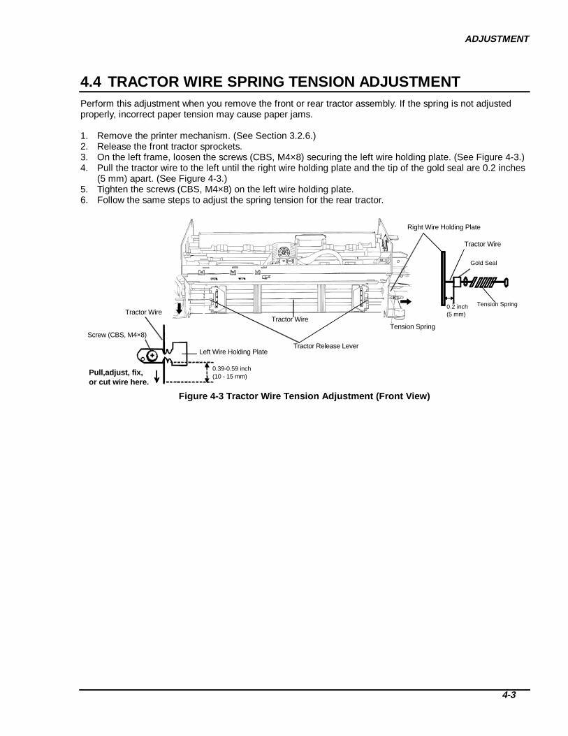
ADJUSTMENT
4-3
4.4 TRACTOR WIRE SPRING TENSION ADJUSTMENTPerform this adjustment when you remove the front or rear tractor assembly. If the spring is not adjustedproperly, incorrect paper tension may cause paper jams.
1. Remove the printer mechanism. (See Section 3.2.6.)2. Release the front tractor sprockets.3. On the left frame, loosen the screws (CBS, M4×8) securing the left wire holding plate. (See Figure 4-3.)4. Pull the tractor wire to the left until the right wire holding plate and the tip of the gold seal are 0.2 inches
(5 mm) apart. (See Figure 4-3.)5. Tighten the screws (CBS, M4×8) on the left wire holding plate.6. Follow the same steps to adjust the spring tension for the rear tractor.
Tractor WireTension Spring
Tension Spring
Gold Seal
0.2 inch(5 mm)
Tractor Wire
Right Wire Holding Plate
0.39-0.59 inch(10 - 15 mm)
Left Wire Holding Plate
Tractor Wire
Screw (CBS, M4×8)
Tractor Release Lever
Pull,adjust, fix, or cut wire here.
Figure 4-3 T ractor Wire Tens ion Adjustment (Front View)
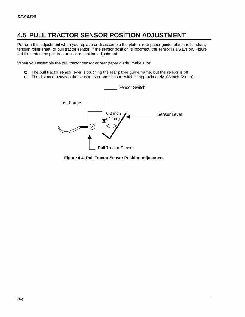
DFX-8500
4-4
4.5 PULL TRACTOR SENSOR POSITION ADJUSTMENTPerform this adjustment when you replace or disassemble the platen, rear paper guide, platen roller shaft,tension roller shaft, or pull tractor sensor. If the sensor position is incorrect, the sensor is always on. Figure4-4 illustrates the pull tractor sensor position adjustment.
When you assemble the pull tractor sensor or rear paper guide, make sure:
The pull tractor sensor lever is touching the rear paper guide frame, but the sensor is off. The distance between the sensor lever and sensor switch is approximately .08 inch (2 mm).
Left Frame
Sensor Switch
Sensor Lever
Pull Tractor Sensor
0.8 inch(2 mm)
Figure 4-4. Pull T ractor Sensor Posit ion Adjustment
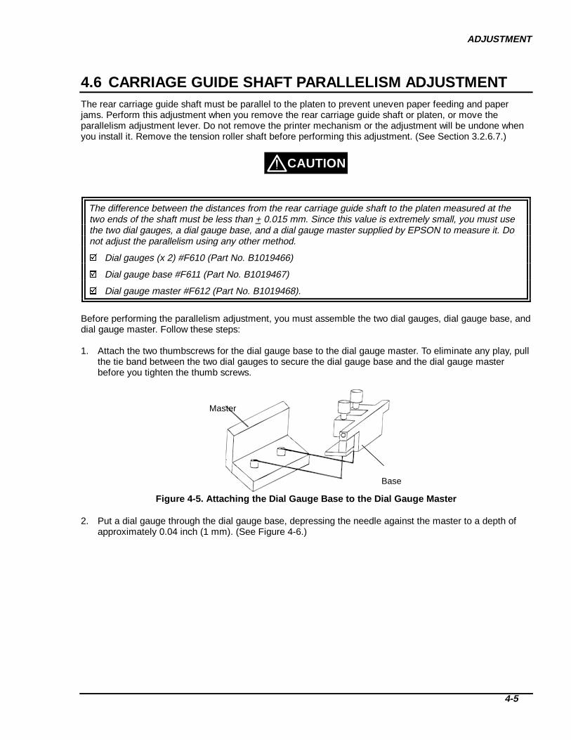
ADJUSTMENT
4-5
4.6 CARRIAGE GUIDE SHAFT PARALLELISM ADJUSTMENTThe rear carriage guide shaft must be parallel to the platen to prevent uneven paper feeding and paperjams. Perform this adjustment when you remove the rear carriage guide shaft or platen, or move theparallelism adjustment lever. Do not remove the printer mechanism or the adjustment will be undone whenyou install it. Remove the tension roller shaft before performing this adjustment. (See Section 3.2.6.7.)
The difference between the distances from the rear carriage guide shaft to the platen measured at thetwo ends of the shaft must be less than + 0.015 mm. Since this value is extremely small, you must usethe two dial gauges, a dial gauge base, and a dial gauge master supplied by EPSON to measure it. Donot adjust the parallelism using any other method.
Dial gauges (x 2) #F610 (Part No. B1019466)
Dial gauge base #F611 (Part No. B1019467)
Dial gauge master #F612 (Part No. B1019468).
Before performing the parallelism adjustment, you must assemble the two dial gauges, dial gauge base, anddial gauge master. Follow these steps:
1. Attach the two thumbscrews for the dial gauge base to the dial gauge master. To eliminate any play, pullthe tie band between the two dial gauges to secure the dial gauge base and the dial gauge masterbefore you tighten the thumb screws.
Master
Base
Figure 4-5. Attaching the Dial Gauge Base to the Dial Gauge Master
2. Put a dial gauge through the dial gauge base, depressing the needle against the master to a depth ofapproximately 0.04 inch (1 mm). (See Figure 4-6.)
CAUTION

DFX-8500
4-6
Hex screw
Gauge needle
Figure 4-6. Dial Gauge Setup
3. Tighten the hexagonal screw securing the dial gauge to the base.4. Install the second gauge the same way. Set both gauges to exactly the same reading, then tighten the
hexagonal screw. (See Figure 4-7.)
Gauge needle
Hex screw
Figure 4-7. Installing the Second Dial Gauge
5. Set the black marker to the "0" position. (See Figure 4-8.)
Figure 4-8. Setting the Gauges to Zero
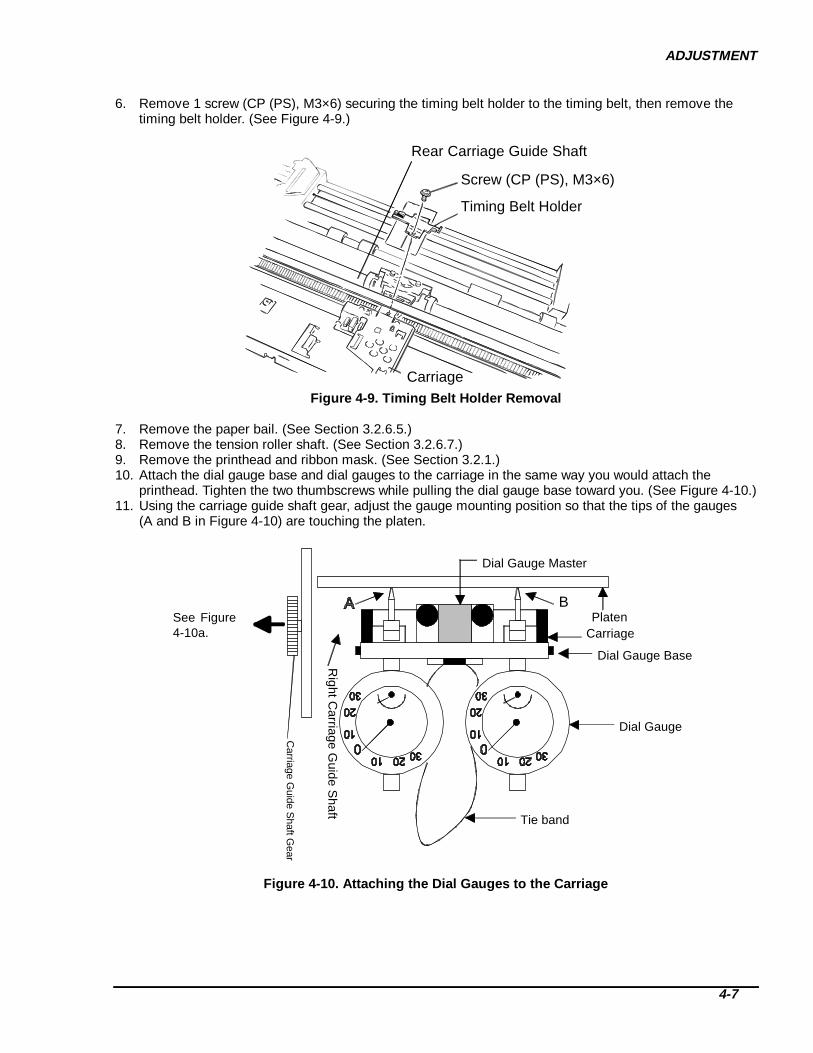
ADJUSTMENT
4-7
6. Remove 1 screw (CP (PS), M3×6) securing the timing belt holder to the timing belt, then remove thetiming belt holder. (See Figure 4-9.)
Screw (CP (PS), M3×6)
Timing Belt Holder
Carriage
Rear Carriage Guide Shaft
Figure 4-9. Timing Belt Holder Removal
7. Remove the paper bail. (See Section 3.2.6.5.)8. Remove the tension roller shaft. (See Section 3.2.6.7.)9. Remove the printhead and ribbon mask. (See Section 3.2.1.)10. Attach the dial gauge base and dial gauges to the carriage in the same way you would attach the
printhead. Tighten the two thumbscrews while pulling the dial gauge base toward you. (See Figure 4-10.)11. Using the carriage guide shaft gear, adjust the gauge mounting position so that the tips of the gauges
(A and B in Figure 4-10) are touching the platen.
Platen
Dial Gauge Base
Dial Gauge Master
Dial Gauge
Tie band
B
Carriage
Right C
arriage Guide S
haft
Carriage G
uide Shaft G
ear
See Figure4-10a.
Figure 4-10. Attaching the Dial Gauges to the Carriage

DFX-8500
4-8
Stopper
Platen Gap Transmission Gear
Carriage Guide Shaft Gear
Figure 10a. Carriage Guide Shaft G ear Posit ioning
12. Measure the distance between the platen and the carriage guide shaft on the left end of the platen. Thenmeasure the distance between the platen and the carriage guide shaft on the right end of the platen, andcompare the two values. (Figure 4-11 shows the measurement position and the parallelism adjust leveroperation.)
Note: Rotate the carriage motor pulley to move the carriage. Do not touch the dial gauges.
Carriage Parallelism
Carriage Motor
Motor Pulley
2.8 inches(70 mm)
0
10
10 20
20
30
30Right Side Frame
Adjust Lever
2.8 inches(70 mm)
Figure 4-11. Carriage Guide Shaft P arallelism Adjustment
13. If the left measurement is greater than the right, move the carriage parallelism adjust lever in thedirection shown by the white arrow in Figure 4-11. If the right measurement is greater than the left,move the lever in the direction shown by the black arrow.
14. Repeat steps 11 and 12 until the difference between the distance measured at the two positions is lessthan + 0.015 mm.
15. When the difference is within the specified range, tighten the 2 screws (CP (PS), M4×6) securing theparallelism adjustment lever. Then measure the distances again as described in step 11.
16. If the difference is within the specified range, apply a screw-locking compound to the two screws. (SeeSection 6.2 for lubrication and adhesive application instructions.)
17. Perform the platen angle adjustment (See Section 4.7.)

ADJUSTMENT
4-9
4.7 PLATEN ANGLE ADJUSTMENTThe platen must make a right angle with the carriage. Perform this adjustment after you remove or replacethe platen or loosen the two hexagonal screws securing the platen to the frame. Do not remove the printermechanism, or the adjustment will be undone when you install it. Remove the tension roller shaft beforeperforming this adjustment. (See Section 3.2.6.7.)
1. Perform the carriage guide shaft parallelism adjustment. (See Section 4.1.5.) After the adjustment isfinished, leave the dial gauge unit on the carriage.
2. Remove the pull tractor sensor. (See Section 3.2.6.10.)3. Loosen (but do not remove) the two hexagonal screws securing the platen stay to both side frames.
(See Figure 4-12.)
Hexagonal Screws (M4×8)
Platen Stay (R)Platen Stay (L)Positioning Tab
Positioning Tab
Right FrameLeft Frame
Figure 4-12. Loosening the Hexagonal S crews
4. Using the carriage guide shaft gear, touch both dial gauge needles to the platen surface. Don’t push theneedles all the way in.
Carriage Guide Shaft Gear
Left Side Frame
Carriage Guide Shaft
Platen
Attach both needles.
See Figure 4-10a.
Figure 4-13. Touching the Needles to the Platen Surface
5. Measure the gauge reading differences in three positions, as shown below. Use the carriage motorpulley to move the carriage with the dial gauge toward the right side. Do not touch the dial gauge unititself. (See Figure 4-15.)

DFX-8500
4-10
010
10 20
20
30
300
10
10 20
20
30
30
Platen
010
10 20
20
30
30010
10 20
20
30
30010
10 20
20
30
30010
10 20
20
30
30
Center Position2.8 inches(70 mm)
2.8 inches(70 mm)
Figure 4-14. M easur ing the Platen Angle (not to scale)
Platen
B
(Angle Adjustment Method)
Up
Down
A
Figure 4-15. Adjusting the Platen Angle
6. If the difference between the two gauge values is more than 0.015 mm at any point, loosen (but do notremove) the 2 hexagonal screws securing the platen stay to the frame, then slowly adjust the platenangle.
7. Tighten the 2 hexagonal screws to secure the platen stay to the frame.
After you perform this adjustment, confirm the carriage guide shaft parallelism value again. If this value istoo large, readjust the carriage guide shaft parallelism and the platen angle until both are correct.
CAUTION
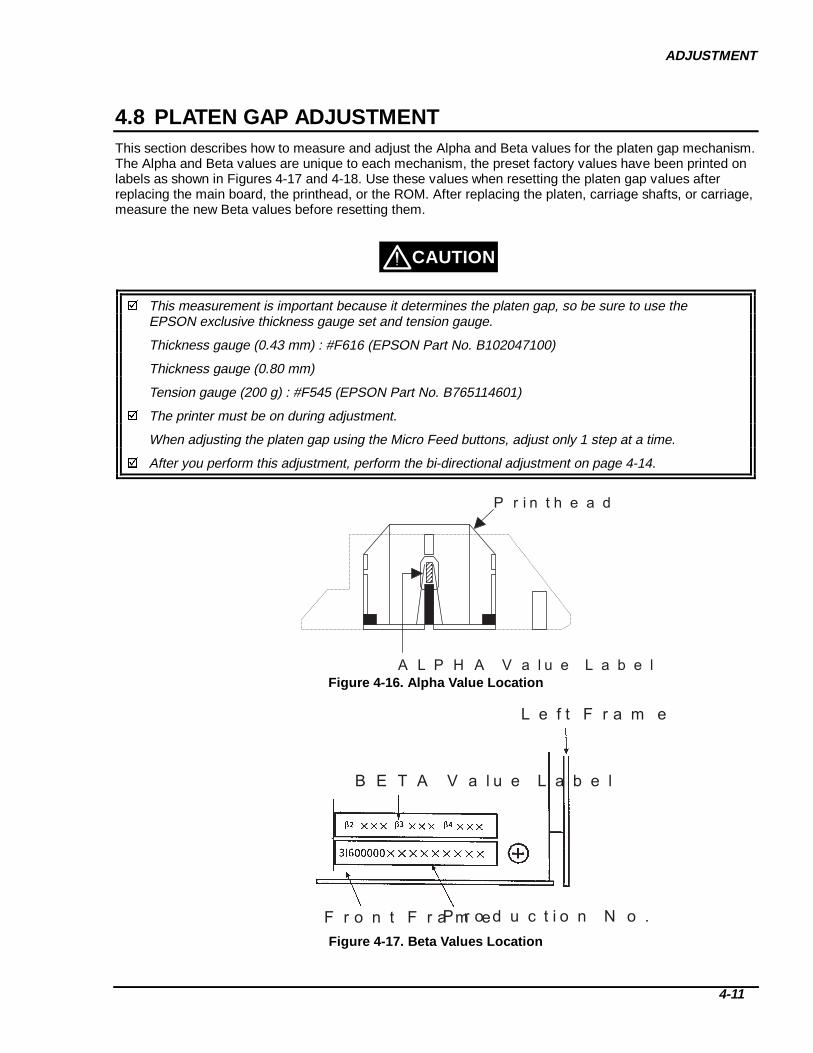
ADJUSTMENT
4-11
4.8 PLATEN GAP ADJUSTMENTThis section describes how to measure and adjust the Alpha and Beta values for the platen gap mechanism.The Alpha and Beta values are unique to each mechanism, the preset factory values have been printed onlabels as shown in Figures 4-17 and 4-18. Use these values when resetting the platen gap values afterreplacing the main board, the printhead, or the ROM. After replacing the platen, carriage shafts, or carriage,measure the new Beta values before resetting them.
This measurement is important because it determines the platen gap, so be sure to use theEPSON exclusive thickness gauge set and tension gauge.
Thickness gauge (0.43 mm) : #F616 (EPSON Part No. B102047100)
Thickness gauge (0.80 mm)
Tension gauge (200 g) : #F545 (EPSON Part No. B765114601)
The printer must be on during adjustment.
When adjusting the platen gap using the Micro Feed buttons, adjust only 1 step at a time.
After you perform this adjustment, perform the bi-directional adjustment on page 4-14.
A L P H A V a l u e L a b e l
P r i n t h e a d
Figure 4-16. Alpha Value Location
L e f t F r a m e
P r o d u c t i o n N o .F r o n t F r a m e
B E T A V a l u e L a b e l
Figure 4-17. Beta Values Location
CAUTION

DFX-8500
4-12
RESETTING THE PLATEN GAP VALUES
To reset the A lpha and Beta values:
1. Remove the paper, ribbon cartridge, and ribbon mask holder from the printer.2. Write down the Alpha value written on the side of the printhead.3. Write down the Beta values written on the label on the inside bottom right corner of the printer
mechanism, under the ribbon cartridge.4. Close the top cover.
Alpha value:5. Turn the printer on while holding down the Tear Off, Micro Feed ↓, and Front/Rear buttons. Hold the
buttons down until the printer beeps once.6. The control panel will display the current Alpha value within 10 seconds. (See Table 4-2.)7. Adjust the Alpha value:
Press the Micro Feed ↓ button to increase the value by 1. Press the Micro Feed ↑ button to decrease the value by 1.
8. Press the LF/FF Load button to save the new Alpha value to the EEPROM and exit adjustment mode.9. Press the Pause/Reset button to write the new Alpha value to the EEPROM and enter Beta adjustment
mode.
Beta values:10. The control panel will display the current Beta 3’ value. (Default = 450)11. Adjust the Beta 3’ value until it is equal to Beta 3 (listed on the mechanism) + 10:
Press the Micro Feed ↓ button to increase the value by 1. Press the Micro Feed ↑ button to decrease the value by 1. Press the Tear Off button to increase the value by 10. Press the Top of Form button to decrease the value by 10.
12. Press the Pause/Reset button to save the Beta 3’ value to the EEPROM.13. The 7-segment LED will flash a 2. This shows the next Beta value to be adjusted, Beta 2. Press the
Micro Feed ↑ button. The control panel will display the current Beta 2 value.14. Adjust the Beta 2 value in the same way you adjusted the Beta 3’ value.15. Press the Pause/Reset button to save the Beta 2 value to the EEPROM.16. The 7-segment LED will flash a 3. This shows the next Beta value to be adjusted, Beta 3. Press the
Micro Feed ↑ button. The control panel will display the current Beta 3 value.17. Adjust the Beta 3 value in the same way you adjusted the Beta 3’ value.18. Press the Pause/Reset button to save the Beta 3 value to the EEPROM.19. The 7-segment LED will flash a 4. This shows the next Beta value to be adjusted, Beta 4. Press the
Micro Feed ↑ button. The control panel will display the current Beta 4 value.20. Adjust the Beta 4 value in the same way you adjusted the Beta 3’ value.21. Press the Pause/Reset button to save the Beta 4 value to the EEPROM.22. Turn off the printer and reinstall the ribbon mask holder and ribbon cartridge
ADJUSTMENT
4-13
MEASURING THE PLATEN GAP VALUES
To measure and enter new Beta values:
1. Remove the paper, ribbon cartridge, and ribbon mask holder from the printer.2. Write down the Alpha value written on the side of the printhead.3. Write down the Beta values written on the label on the inside bottom right corner of the printer
mechanism, under the ribbon cartridge.4. Close the top cover.
To reset the A lpha value:1. Turn the printer on while pressing the Tear Off, Micro Feed ↓, and Front/Rear buttons. Hold the buttons
down until the printer beeps once. The printer performs a platen gap home position seek, and thecarriage moves to column 15.
2. The control panel indicates the current Alpha adjustment value (See Tables 4-1 and 4-2.)3. Enter the Alpha value on the printhead into memory, using the Micro Feed buttons:
Press the Micro Feed ↓ button to increase the value by 1. Press the Micro Feed ↑ button to decrease the value by 1.
4. If you are finished and do not wish to adjust the Beta values, press the LF/FF Load button. The Alphavalue is written to the EEPROM and the adjustment is complete. Turn the power off and install theribbon mask holder and the ribbon cartridge.
5. If you wish to continue on to Beta value adjustment, press the Pause/Reset button. The Alpha value iswritten to the EEPROM, and the printer enters the Beta values write mode.
To measure the Beta values:6. Open the top cover and insert the 0.43 mm thickness gauge into the space between the platen and the
printhead nose. (At this time, do not shift the print head. If you do, return to Step 4.)7. Hook the tension gauge through the hole of the thickness gauge and pull it straight to the right.8. Gradually bring the printhead to the surface of the thickness gauge using the Micro Feed buttons:
Press the Micro Feed ↓ button to increase the value by 1. Press the Micro Feed ↑ button to decrease the value by 1. Press the Tear Off button to increase the value by 10. Press the Top of Form button to decrease the value by 10.The panel indicates the current Beta 3’ adjustment value. (See Table 4-1.)
9. Adjust the Beta 3’ value until the tension gauge shows about 150 (135 - 165) gf, and the thicknessgauge can still move to the right very slowly.
10. Press the Pause/Reset button.11. Remove the thickness gauge, and gradually bring the printhead nose to the platen using the Micro Feed
buttons: Press the Micro Feed ↓ button to increase the value by 1. Press the Micro Feed ↑ button to decrease the value by 1. Press the Tear Off button to increase the value by 10. Press the Top of Form button to decrease the value by 10.The panel indicates the current Beta 2 adjustment value. (See Table 4-1.)
12. Press the Pause/Reset button.13. Insert the 0.43 mm thickness gauge into the space between the platen and the printhead nose.14. Gradually bring the printhead to the surface of the thickness gauge using the Micro Feed buttons:
Press the Micro Feed ↓ button to increase the value by 1. Press the Micro Feed ↑ button to decrease the value by 1. Press the Tear Off button to increase the value by 10. Press the Top of Form button to decrease the value by 10.The panel indicates the current Beta 3 adjustment value. (See Table 4-1.)
15. Press the Pause/Reset button.16. Insert the 0.80 mm thickness gauge into the space between the platen and the printhead nose.

DFX-8500
4-14
17. Gradually bring the printhead to the surface of the thickness gauge using the Micro Feed buttons: Press the Micro Feed ↓ button to increase the value by 1. Press the Micro Feed ↑ button to decrease the value by 1. Press the Tear Off button to increase the value by 10. Press the Top of Form button to decrease the value by 10.The panel indicates the current Beta 4 adjustment value. (See Table 4-1.)
18. Press the Pause/Reset button. All of the measured Beta values are written to the EEPROM.
Note: If the measured Beta values are outside the allowed range (See Table 4-1), the printer sounds sixbeeps and doesn’t write the values to the EEPROM.
19. Turn the printer power off, then reinstall the ribbon mask holder and the ribbon cartridge.
Platen
Tension Gauge
Thickness Gauge(for BETA3' = 0.43 mm)
135 - 165 gf
Figure 4-18. Using the Thickn ess Gauge
Table 4-1. Beta Values AdjustmentBeta No. Reference Thickness Gauge A llowed Value Default Value*Beta 3' 0.43 mm with 150 gf tension - -Beta 2 0.00 mm 367 – 419 408Beta 3 0.43 mm 405 – 437 435Beta 4 0.80 mm 418 – 475 461*1: After the EEPROM is reset.
Table 4-2. LED Value DisplayLED* Off OnRibbon (Bi-d. adjustment) (platen gap adjustment)
+ (positive) 300
(negative)400
PauseTop of FormTear OffCopyPitchFont
Each LEDequals +10.
7 Segment 0 to 9

ADJUSTMENT
4-15
4.9 BI-DIRECTIONAL PRINTING ADJUSTMENTThe purpose of this adjustment is to correct the printer mechanism parameters that control bi-directionalprinting. If the adjustment is not performed correctly, bi-directional printing may be misaligned, or thecarriage might operate incorrectly. Before performing this procedure, be sure that the following adjustmentshave been completed correctly:
Carriage Timing Belt Tension Adjustment Carriage Guide Shaft Parallelism Adjustment Platen Angle Adjustment Platen Gap Motor Value Adjustment
The parameters to be written to the EEPROM in this adjustment are:
1. Printhead flying time adjustment value (Flight Time)2. Bi-directional printing alignment value for each print speed: Super Draft, Draft, and NLQ
CAUTION
Before you perform the Bi-D adjustment, turn DIP switch 1-6 off. Otherwise, the adjustment won’twork.
If you replace the main board, you must perform the platen gap adjustment before performing the bi-directional printing adjustment.
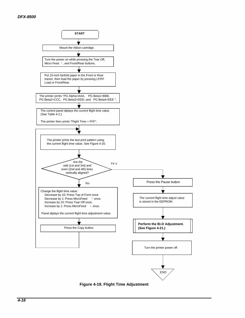
DFX-8500
4-16
END
Ye s
No
START
Turn the power on while pressing the Tear Off, Micro Feed ↑, and Front/Rear buttons.
Put 15-inch fanfold paper in the Front or Reartractor, then load the paper by pressing LF/FF Load or Front/Rear.
The printer prints "PG Alpha=AAA, PG Beta1=BBB, PG Beta2=CCC, PG Beta3=DDD, and PG Beta4=EEE ".
The control panel diplays the current flight time value(See Table 4-2.).
The printer then prints "Flight Time = FFF".
The printer prints the test print pattern using the current flight time value. See Figure 4-20.
Are the odd (1st and 3rd) and
even (2nd and 4th) lines vertically aligned?
Change the flight time value: Decrease by 10: Press Top of Form once. Decrease by 1: Press MicroFeed ↑ once. Increase by 10: Press Tear Off once. Increase by 1: Press MicroFeed ↓ once.
Panel diplays the current flight time adjustment value.
Press the Copy button.
The current flight time adjust value is stored in the EEPROM.
Perform the Bi-D Adjustment.(See Figure 4-21.)
Turn the printer power off.
Mount the ribbon cartridge.
Press the Pause button.
Figure 4-19. Flight Time Adjustment

ADJUSTMENT
4-17
40 COLUMNS 40 COLUMNS56 COLUMNS
TTTTTTTTTTTTTTTTTTTTT
TTTTTTTTTTTTTTTTTTTTTTTTTTTTTTTTTTTTTTTTTTTTTTTTTTTTTTTTTTTTTTT
Increase flight timeDecrease flight time
Figure 4-20. Flight Time Pattern

DFX-8500
4-18
Bi-D. Adjustment Mode
Super Draft Print Mode
No
Yeso
The control panel diplays the current Bi-D value.
The printer prints "Speed = AAA Bid adjust = BBB".BBB* is the current Bi-D value.
Are the odd (1st and 3rd) and
even (2nd and 4th) lines vertically aligned?
The printer prints the test print pattern using the current value.
Change the Bi-D value. Decrease by 10: Press Top of Form once. Decrease by 1: Press MicroFeed ↑ once. Increase by 10: Press Tear Off once. Increase by 1: Press MicroFeed ↓ once.The control panel diplays the current Bi-D value.
Adjustment
Return
Adjustment
Draft Print Mode
Adjustment
NLQ Print Mode
Adjustment
No Are alladjustments complete
and correct?
END
Turn the printer off.
Press the Pause button.The current adjustment value is stored in the EEPROM.
Super DraftSpeed BBB
SdrSpdDrfSpd
NLQSpdDraftNLQ
*BBB Settings
Press the Copy button.Yes
Figure 4-22. Bi-D Adjustment
CHAPTER 5TROUBLESHOOTING
5.1 TROUBLESHOOTING INFORMATION___________________________________________1Error Messages _____________________________________________________________________________ 1Bypassing the Interlock Switch and Cover Open Sensor _____________________________________________ 3Coil Resistance and Printhead Cable Signals ______________________________________________________ 4Unit Replacement ___________________________________________________________________________ 6
5.2 CIRCUIT BOARD REPAIR _____________________________________________________14C204 PSB/PSE Board Repair _________________________________________________________________ 14C204 Main/DRV/DRV-B Boards Repair_________________________________________________________ 16Printer Mechanism Repair____________________________________________________________________ 19

TROUBLESHOOTING
5-1
5.1 TROUBLESHOOTING INFORMATIONThis chapter lists various problems that can occur with the DFX-8500 and provides possible solutions. Nospecial tools, other than a digital multi-meter, are necessary to troubleshoot at the unit level. Somecomponent-level troubleshooting may require an oscilloscope.
ERROR MESSAGESThe DFX-8500 indicates errors using beeps. Tables 5-1 and 5-2 list standard errors.
Table 5-1. Error/Warning Beeper Information
Error/Warning PauseLED
Paper OutLED
RibbonLED
Beeper Description
Printhead hot Blinking Off Off —Printhead fan hot Blinking Off Off —Paper out On On Off . . . This error occurs when the
printer fails to load a sheet.(Three 100-ms beeps with a100-ms interval.)
Cover open ON Off Off . . . This error occurs when theprinter’s cover is open.
Paper changeincomplete
On Off Off . . . This error occurs when theprinter fails to change the paper.
Paper backfeedincomplete
On Blinking Off . . .
Paper size error ON Off Off . . . This error occurs when the setpaper width and the currentpaper size are different.
Paper jam ON Blinking Off - - - - - This error occurs when theprinter fails to eject a sheet.(Five 500-ms beeps with a100-ms interval.)
Ribbon jam On Off Blinking - - - - - This error occurs when theribbon jams or when no ribbon isinstalled.
Carriage motorerror
On Blinking Blinking - - - - - This error occurs when thecarriage deceleration time isabnormal.
Illegal paneloperation
— — — —

DFX-8500
5-2
Table 5-2. Fatal Error Information
Fatal Error 7-segmentLED *
Beeper † Description Note ‡
Carriage motorcircuit short
1 - The isolation resistance in the carriagemotor is too low.
Auto power offafter 12 seconds
Cutter error 2 - - • The optional cutter cable is notconnected securely.
• The optional cutter is defective.
Auto power offafter 12 seconds
Platen gaperror
3 - - - • The PG home sensor is broken.• The PG motor is broken.• The parallelism adjustment is
incorrect.• PG adjustment values are incorrect.• PG motor pinion is too tight against
the PG transmission gear.
Auto power offafter 12 seconds
Carriage lockerror
4 - - - - The carriage is locked. Auto power offafter 12 seconds
Encoder error 4 - - - - The encoder sensor is defective. Auto power offafter 12 seconds
Carriage loadmeasurementerror
6 - - - - - - PW sensor is defective. Auto power offafter 12 seconds
Head fan error 7 - - - - - - - • The head fan driver IC is shorted.• The head fan is defective.
Printhead poweroff immediately
Printheadcircuit short
8 - - - - - - - - • The printhead driver IC is shorted.• The printhead coil is defective.
Printhead poweroff immediately
RAM checkerror
9 - - - - - - - - - The DRAM on the main board isdefective.
Auto power offafter 12 seconds
Paper memorysetting error
a - - - - - - - - - - - -
EEPROM datacompare error
b - - - - - - - - - - - The EEPROM is defective.
Tractor changeerror
c - - - - - - - - - - - - The tractor select mechanism or ribbonfeed motor is defective.
Auto power offafter 12 seconds
Internal CPUerror
d The main board is defective. Auto power offafter 12 seconds
*: During a fatal error, the 7 segment LED alternately flashes an “E” and the error number.†: 500 ms beeps with 100 ms intervals.‡: Turn the printer power off while the 7 segment LED is on, or the printer will shut down. The printer will not
turn back on for 5 minutes after the printer shuts down automatically.

TROUBLESHOOTING
5-3
BYPASSING THE INTERLOCK SWITCH AND COVER OPEN SENSORTo print with the top cover open or removed, you need to bypass the interlock switch and cover open sensor.These sensors automatically disable printing when the top cover is open.
Cover Open Sensor
Interlock Switch
CN3
ConnectorJunction Board
C204 Main Board
Figure 5-1. Interlock Switch and Co ver Open Sensor
The interlock switch and cover open sensor are attached. To bypass the interlock switch and the cover opensensor, follow these steps:
1. Remove the left side cover.2. Remove the interlock switch and cover open sensor from the housing.3. Insert a half-inch spacer (for example, an eraser) as shown in Figure 5-2.
0.51 inch(13 mm)
Spacer
Interlock Switch
Cover Open Sensor
To CN3 on the Main Board
To Connector Junction Board
Figure 5-2. Byp assing the Interlock Switch and Co ver Open Sensor

DFX-8500
5-4
COIL RESISTANCE AND PRINTHEAD CABLE SIGNALSThe following table provides the coil resistance for the motor, head fan, plunger, and printhead.
Table 5-3. Motor, Fan, Plunger, and Printhead Coil ResistancePart Coil ResistanceCarriage (CR) motor 1.66 Ω + 10 %Print Feed (PF) motor 2.80 Ω + 10 % at 25oCRibbon Feed (RF) motor 150 Ω + 10 % at 25oCPlaten Gap (PG) motor 250 Ω + 18 Ω at 25oCHead fan 61 Ω + 4.3 Ω at 25oCPlunger 9 Ω + 5 % at 25oCPrinthead 2.93 Ω + 0.2 Ω at 25oC
Printhead Cable Board
Printhead Cable Protection Sheet
Printhead FPC
Double-sided Adhesive TapeShield Cable
123
45
C
B
A
Figure 5-3. Printhead FPC

TROUBLESHOOTING
5-5
FPC A
FPC B
FPC C
Load Pattern
: Printhead coil GND side: Printhead coil P/S side: Printhead thermistor
MA : Fan motor phase AMB : Fan motor phase BMC : Fan motor commonMT : Fan motor thermistor
PWD : Paper width sensor+5V : +5 VDCENCA: Encoder AGND : GroundHT : Printhead thermistor
P/S : Power supply (+37 VDC)ENCB: Encoder B
Figure 5-4. Printhead Cable Signals

DFX-8500
5-6
UNIT REPLACEMENT1. The printer does not operate when power is turned on.
END
Replace the C204 MAIN board, C204 DRV board, and/or C204 DRV-B board.
Is the AC input voltage normal?
No
Yes
Use the correct AC voltage.
Has fuse F1 on the C204 power
supply board blown?
Yes
No
When youturn on power
again, does thenew fuse also
blow?
No
Yes
Replace the C power supply board.
No Is the output voltage
normal?
Yes
No
Yes
Is the fault corrected?
See Section 5.3 torepair the printermechanism.
Check all motors, solenoid, printhead,and drivers using a multimeter.
Are they within normal
range?
Yes
No
END
Yes
Is the fault corrected?
Retest
Is the problem
fixed? No
END
Yes
No
Does theprinter beep
before it dies?
No
YesCheck Table 5-1, ErrorCodes.
START
Replace the fuse F1 anddisconnect CN2, CN3, and CN4 on the C204 power supply Board.
Reconnect CN2, CN3, and CN4and turn on the printer.
204
Disconnect the PSB from themain board and measure the output voltage from the PSB.
Connect only the main board to the PSB, disconnect all other connectors from the main board, and check thevoltage again.
Is the output voltage
normal?
Replace the main board.
No
Yes
Replace the bad motor, solenoid, printhead, or DRV boards.
Note: The printer has a 5 minute shut down safetybuilt into the main board. If an error occurs andthe printer shuts down after 12 seconds or less, please do not assume it is a PSB problem.
In order to prevent the printer from shutting downfor 5 minutes, do the following:
1. Turn off the printer within 12 seconds.2. Open the top cover within 12 seconds. (this will cause a cover open error, which takes precedence over the shut down.)

TROUBLESHOOTING
5-7
2. Carriage operation is abnormal.
END
START
No
Yes
Reinsert the connectors.
No
Yes
Manually move the carriage to see if
movement is smoothor not.
Not smooth
Refer to Section 5.3, Repairof the Printer Mechanism.
No
Yes
END
Smooth
END
No
Yes
No
Yes
NOTE: Make sure these connectors are secure:
Replace the C204 main board and/orC204 DRV board.
Are theconnectors listed in
the note belowinserted securely?
Is the problemfixed?
Is the problemfixed?
Is the problemfixed?
Replace or clean the defective component .
Interlock switch connector on connector junction boardCarriage motor connector on connector junction boardPrinthead connector on printhead junction boardCN4 on the main board
Check the CR motor and CR motor
drivers using a multimeter. Are they OK?
Check the CR encoder belt and
encoder sensor.Are they clean?
No
Yes

DFX-8500
5-8
3. Carriage operation is normal, but the self-test is printed incorrectly (1/3).
Re insert co rrectly.
Yes
START
No
Yes
No
END
END
Perform the self-test.
No
Yes
Perform the bidirectionalprinting adjustment.
No
Yes
Yes
No
A
Are anydots missing or
delayed?
NOTE: Check the following connectors:
Are the connectorslisted in the note below
inserted securely?
Is the problemfixed?
Is the problemfixed?
Does theprinter perform the
self-test?
Check the printhead cable and terminal pins. Replace any bad parts.
Three printhead junction board connectors to the printheadCN1 on the main boardCN2 on the main boardCN1 on the C204 DRV-B board

TROUBLESHOOTING
5-9
4. Carriage operation is normal, but the self-test is printed incorrectly (2/3).
Refer to Section 5.3, Repair of the Printer Mechanism.
.
Check the printhead drivers.
NoIs the printhead resistance
correct?
No
Yes
Are thedrivers OK?
A
Yes
No
Yes
B
No
Check the printhead drivers.
NoAre thedrivers OK?
Yes
END
Refer to Section 5.3, Repair of the Printer Mechanism.
B
Yes
Check the printhead coil resistance.
If the ribbon mask is not seated properly, reseat or replace it.
Replace the DRV board and the printhead.
Replace the printhead .
Is the problemfixed?
Is the problemfixed?
Replace the DRV board.

DFX-8500
5-10
5. Carriage operation is normal, but the self-test is printed incorrectly (3/3).
B
Yes
Perform bidirectionaladjustment.
END
No
Is the print correct?
Go back to Section 5.3, Repairof the Printer Mechanism, andcheck for other problems.
Perform bidirectionaladjustment.
END
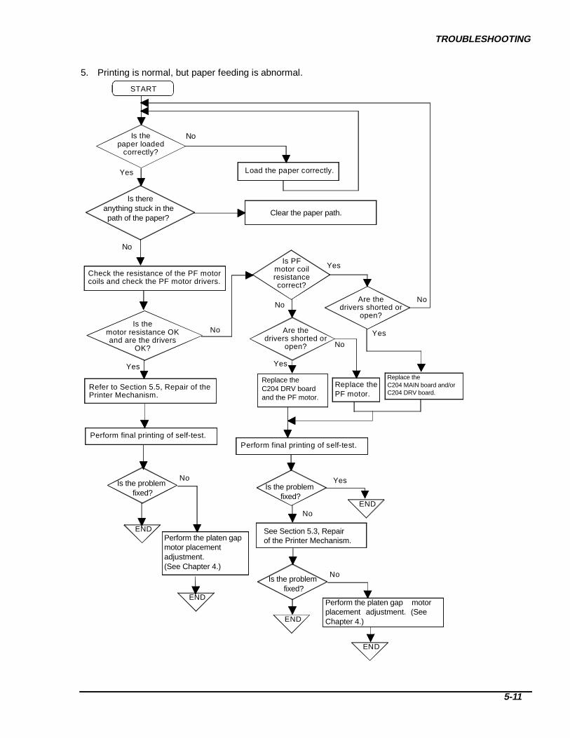
TROUBLESHOOTING
5-11
5. Printing is normal, but paper feeding is abnormal.
Are the drivers shorted or
open?
Load the paper correctly.
START
Yes
Is the paper loaded
correctly?
Yes
Is PFmotor coilresistancecorrect?
Yes
No
Yes
END No
No
Replace thePF motor.
Check the resistance of the PF motor coils and check the PF motor drivers.
Is the
motor resistance OKand are the drivers
OK?
No
Refer to Section 5.5, Repair of the Printer Mechanism.
Are the drivers shorted or
open?
Yes
Perform final printing of self-test.
END
No
Yes
END
No
END
END
Perform final printing of self-test.
No
Replace the C204 DRV boardand the PF motor.
Replace the C204 MAIN board and/orC204 DRV board.
Perform the platen gapmotor placement adjustment. (See Chapter 4.)
Perform the platen gap motor placement adjustment. (See Chapter 4.)
Is the problemfixed?
Is the problemfixed?
Is the problemfixed?
See Section 5.3, Repairof the Printer Mechanism.
No
Is there anything stuck in the path of the paper?
No
Clear the paper path.

DFX-8500
5-12
7. Control panel operation is abnormal.
Replace the C PNL board.
Replace the C Ma in board.
Do theswitches work
correctly?
Reinsert connector CNcorrectly.
START
Do the buttons work?
END
END
Replace the C Main board.
Yes No
No
Yes
No END
Replace the C PNL board.
No
No
Yes
Yes
Yes
END
END
Using a multimeter, checkthe switches on theC PNL board.
5
204
204
204
204
204
Is CN5between the C204 Main
and C204 PNL board connected correctly?
Is the problemfixed?
Is the problemfixed?

TROUBLESHOOTING
5-13
8. Data sent by the host computer is printed incorrectly.
Note : The flowchart below assumes the host computer is operating normally.
Troubleshoot printer using theprevious flowcharts.
Run the self-test.
START
Is the self-test printed correctly? No
Yes
Replace C MAIN board.
Check the cable connectionfrom the host computer.
Which I/F are you using?
Built-in Parallel
Serial orOptional
Yes
Replace cable.
No
END END
Yes
If youare using a
serial I/F, is yourcable a null modem
cable?
No
Yes
Replace C MAIN board.
END
If you areusing a Type B
optional I/F for a network, isthe network configured
correctly?
Not using serial.
Yes
Replace Type B interface.
END
Reconfigure network.
END
No
Set switchescorrectly.
END
No Are the DIPswitches set correctly?(See Tables 1-16,1-21, 1-22,and 1-23.)
204
204
Is your parallel cable a
shielded, twisted-pair cable shorter than 6 feet, and does it
work with another printer?
Can you printfrom DOS?
Yes
No Check the software application setup
END

DFX-8500
5-14
5.2 CIRCUIT BOARD REPAIRThis section describes troubleshooting and repair procedures for the DFX-8500 circuit boards. By referringto the checkpoints below, you can determine which component is defective and perform the proper repairprocedure. The tables have four columns:
Symptom: Common printer problems Cause: Possible causes of each symptom Checkpoint: Troubleshooting checks to help isolate your problem Solution: Repair instructions
C204 PSB/PSE BOARD REPAIRTable 5-4 describes the major components of the C204 PSB/PSE board. Table 5-5 contains troubleshootinginstructions.
Table 5-4. C204 PSB/PSE Board Main Parts ListLocation DescriptionDB1 Diode bridgeTY1 TRIACQF101 Switching FET for VP1 and VP2QF201 Switching FET for VP3 and +5 VDCIC101 PWM switching controllerIC204 +5 V regulator IC
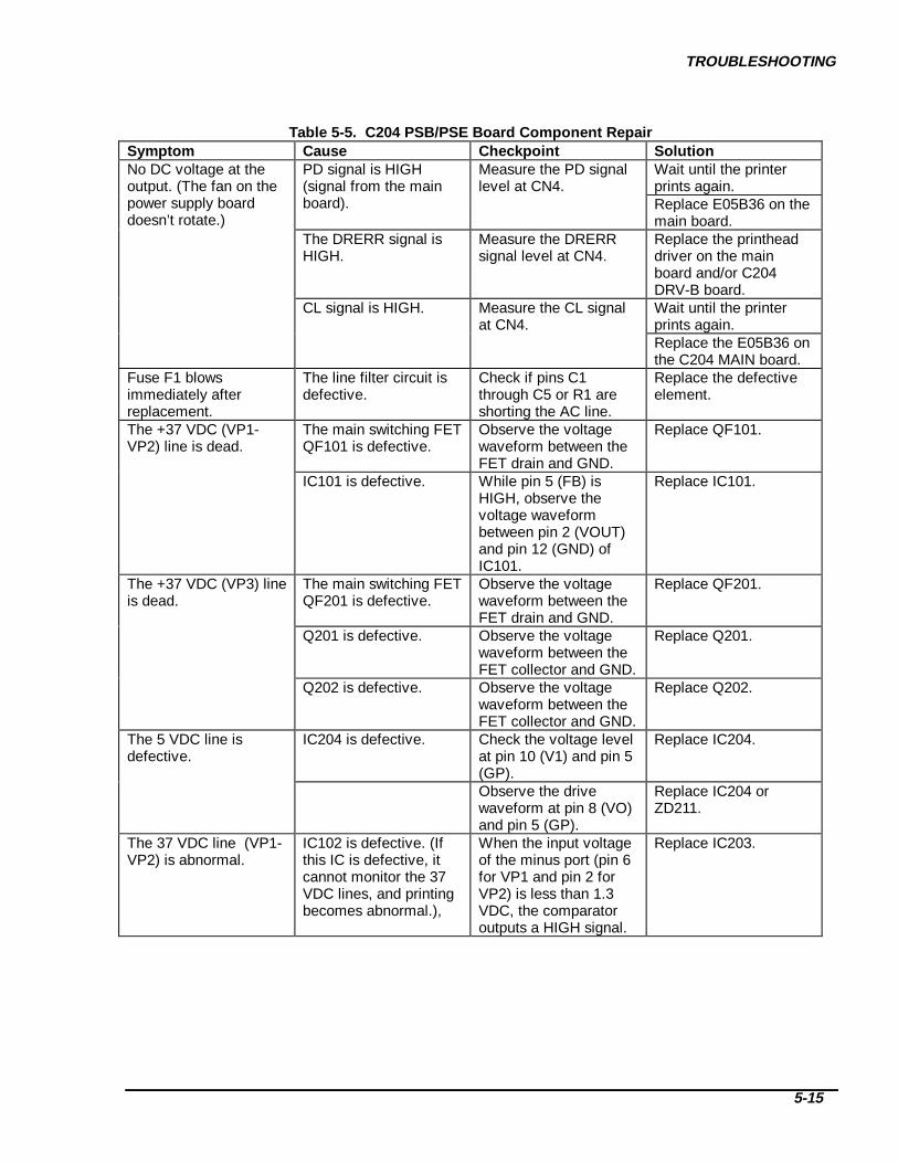
TROUBLESHOOTING
5-15
Table 5-5. C204 PSB/PSE Board Com ponent RepairSymptom Cause Checkpoint Solution
Wait until the printerprints again.
No DC voltage at theoutput. (The fan on thepower supply boarddoesn’t rotate.)
PD signal is HIGH(signal from the mainboard).
Measure the PD signallevel at CN4.
Replace E05B36 on themain board.
The DRERR signal isHIGH.
Measure the DRERRsignal level at CN4.
Replace the printheaddriver on the mainboard and/or C204DRV-B board.Wait until the printerprints again.
CL signal is HIGH. Measure the CL signalat CN4.
Replace the E05B36 onthe C204 MAIN board.
Fuse F1 blowsimmediately afterreplacement.
The line filter circuit isdefective.
Check if pins C1through C5 or R1 areshorting the AC line.
Replace the defectiveelement.
The +37 VDC (VP1-VP2) line is dead.
The main switching FETQF101 is defective.
Observe the voltagewaveform between theFET drain and GND.
Replace QF101.
IC101 is defective. While pin 5 (FB) isHIGH, observe thevoltage waveformbetween pin 2 (VOUT)and pin 12 (GND) ofIC101.
Replace IC101.
The +37 VDC (VP3) lineis dead.
The main switching FETQF201 is defective.
Observe the voltagewaveform between theFET drain and GND.
Replace QF201.
Q201 is defective. Observe the voltagewaveform between theFET collector and GND.
Replace Q201.
Q202 is defective. Observe the voltagewaveform between theFET collector and GND.
Replace Q202.
The 5 VDC line isdefective.
IC204 is defective. Check the voltage levelat pin 10 (V1) and pin 5(GP).
Replace IC204.
Observe the drivewaveform at pin 8 (VO)and pin 5 (GP).
Replace IC204 orZD211.
The 37 VDC line (VP1-VP2) is abnormal.
IC102 is defective. (Ifthis IC is defective, itcannot monitor the 37VDC lines, and printingbecomes abnormal.),
When the input voltageof the minus port (pin 6for VP1 and pin 2 forVP2) is less than 1.3VDC, the comparatoroutputs a HIGH signal.
Replace IC203.

DFX-8500
5-16
C204 MAIN/DRV/DRV-B BOARDS REPAIRTable 5-6 includes troubleshooting procedures.
Table 5-6. C204 Main/DRV/DRV-B Boards Component RepairSymptom Cause Checkpoint Solution
The printer doesnot operate at all.
The DRERR signalwas sent to the C204power supply board(HIGH level turns offthe power supply).
Check the level of the DRERR signalat CN10, or check the VP1 and VP2voltage.
Replace theprinthead driver onthe main board(VP1) or C204DRV-B board(VP2).
The PD signal wassent to the C204power supply board.(A HIGH signal turnsoff the power supply)
Check the level of the PD signalduring power on and verify thevoltage waveform for the printheaddriver.
Replace theprinthead driver orgate array.
The reset circuit isnot working.
Check the logic level at pin 1 (VOUT)of IC13.
Replace IC13.
The drivercircuits don’toperate at all.
The pull up voltageVX is not beinggenerated.
When the collector of Q15 is high,check the logic level at the collectorof Q14 (VX). When the collector ofQ15 is high, VX is HIGH.
Replace Q15.
The serialinterface is dead.
The level converterIC is defective.
Check the signal level changebetween the in and out ports of IC9.
Replace IC9.
The printer doesnot operate at all.
The control ROM isdefective.
Confirm that the PROM is inserted inthe socket correctly.
Replace IC5.
The gate array (IC1)is defective.
Check pin 86 (D0) of IC1 for a changein the signal (HIGH or LOW).
Replace IC1.
The CPU (IC2) isdefective.
Check the waveform at pin 27 (x1) orpin 28 of the CPU.
Replace CRU1 orIC1.
The DRAM (IC14) isdefective.
Check pin 2 (D0) of IC14 for a changein the signal (HIGH or LOW).
Replace IC14.
The carriageoperatesabnormally.
IC1 on the mainboard is defective.
Check the signals for the carriagemotor phases at pins 204 (CRA), 205(CRB), 206 (CRC), and 5 (CRD) ofIC1.
Replace IC1.
Q16, Q17, Q18, orQ19 on the mainboard is defective.
Check the signals for the carriagemotor phases at collectors Q16(CRA), Q17 (CRB), Q18 (CRC), andQ19 (CRD).
Replace Q16, Q17,Q18, or Q19.
IC1 doesn’t work. The voltage level between the anodeand cathode of ZD2 is about 6.2 V.
Replace ZD2, Q34,or Q35.
IC1 on the C204DRV board isdefective.
Check the signals for the carriagemotor phases at pins 14 (IN_A) and10 (OUT1) of IC1.
Replace IC1.
. Measure the voltage level at pins 10(OUT1) and 5 (GP) of IC1 when thecarriage is operating. (The normalvoltage level is approximately 37VDC.)
Replace IC1.
IC3 on the C204DRV board isdefective.
Observe the waveform at pin 1 ofIC3.
Replace IC3.

TROUBLESHOOTING
5-17
Table 5-6. C204 Main/DRV/DRV-B Boards Component Repair (continued)Symptom Cause Checkpoint Solution
The carriageoperatesabnormally.
The carriage encodersensor is defective.
Observe the carriage encoder sensoroutput signal at pins 4 (ENCA) and 3(ENCB) of CN4 on the main board.
Replace thecarriage encodersensor.
Carriage operation isunstable (due to alack of motor torque).
Check the switching waveform for Q5,Q6, and Q7.
Replace theabnormal transistor.
Paper feeding isabnormal.
The CPU (IC2) onthe main board isdefective.
Check the PF motor phase drivesignals at pins 2 through 5 of IC2.
Replace IC2.
IC2 on the C204DRV board isdefective.
At IC2, check the output signals forpins 2 (OUT_A), 3 (OUTXA), 6(OUT_B), and 7 (OUTXB).
Replace IC2.
Ribbon feeding isabnormal.
The CPU (IC2) onthe main board isdefective.
Check the RF motor phase drivesignals at pins 6 through 9 of IC2.
Replace IC2.
The commonswitching transistoron the C204 DRVboard is defective.
Check the collector voltage of Q21. Replace Q20 orQ21.
The phase switchingtransistor on theC204 DRV board isdefective.
For transistors Q22 through Q25,observe the input signal from theCPU (base) and the output signal(collector).
If there is no outputsignal, replace theabnormal transistor.
Fuse F1 on the C204DRV board isdefective.
Check if fuse F1 is defective. Replace F1.
The head fanoperation isabnormal.
IC1 on the mainboard is defective.
Observe the PG motor phase signalat pins 163 (FANA) and 164 (FANAX)of IC1.
Replace IC1.
Q10 or Q11 on themain board isdefective.
Observe the head fan phase drivevoltage level for pins 25 (HFANA) and17 (HFANB) of CN1. (The normalvoltage is approximately 37 VDC.)
Replace Q10 orQ11.
The PG motoroperatesabnormally.
IC1 on the mainboard is defective.
Observe the PG motor phase signalat pins 10 (PGA), 12 (PGB), 14(PGAX), and 13 (PGBX) of IC1.
Replace IC1.
The commonswitching transistoron the C204 DRVboard is defective.
Check the collector voltage of Q11. Replace Q10 orQ11.
The phase switchingtransistor on theC204 DRV board isdefective.
For transistors Q12 through Q15,observe the output signal (collector).
If there is no outputsignal, replace theabnormal transistor.
Fuse F2 on the C204DRV board isdefective.
Check fuse F2. Replace F2.
The PG sensor isdefective.
Observe the PG sensor output signalat pins 35 (PGENCA) and 34(PGENCB) of CN14.
Replace the PGsensor.

DFX-8500
5-18
Table 5-6. C204 Main/DRV/DRV-B Boards Component Repair (continued)Symptom Cause Checkpoint Solution
The PG homeposition sensor isdefective.
Check the PG HP sensor signal levelat pin 36 (PGHOME) of CN14. (PGhome = LOW; other = HIGH)
Replace the PGhome positionsensor.
The plunger isdefective.
Fuse F3 is defective Check fuse F3. Replace F3.
IC1 on the mainboard is defective.
When paper is loaded into the printer,look at the switching signal at pins 16(PLP) and 17 (PLN)of IC1.
Replace IC1.
Plunger drivetransistor on theC204 DRV board isdefective.
Observe the Q31 collector voltage atpaper loading.
Replace Q31, Q30,or Q32.
The self-testprints incorrectly.
IC1 on the mainboard is defective.
Observe the output signal at pins136-181 of IC1.
Replace IC1.
The head driverFETs on the mainand/or C204 DRV-Bboards are defective.
Observe the voltage waveform ateach FET drain side.
Replace theabnormal FET.
The CPU (IC2) onthe main board isdefective.
Observe the signals at pins 38 (PTS1)and 42 (PTS2) of IC2.
Replace IC2.
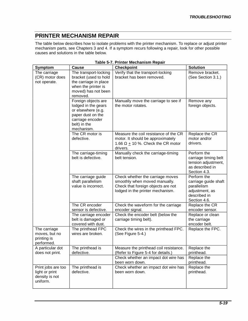
TROUBLESHOOTING
5-19
PRINTER MECHANISM REPAIRThe table below describes how to isolate problems with the printer mechanism. To replace or adjust printermechanism parts, see Chapters 3 and 4. If a symptom recurs following a repair, look for other possiblecauses and solutions in the table below.
Table 5-7. Printer Mechanism RepairSymptom Cause Checkpoint SolutionThe carriage(CR) motor doesnot operate.
The transport-lockingbracket (used to holdthe carriage in placewhen the printer ismoved) has not beenremoved.
Verify that the transport-lockingbracket has been removed.
Remove bracket.(See Section 3.1.)
Foreign objects arelodged in the gearsor elsewhere (e.g.paper dust on thecarriage encoderbelt) in themechanism.
Manually move the carriage to see ifthe motor rotates.
Remove anyforeign objects.
The CR motor isdefective.
Measure the coil resistance of the CRmotor. It should be approximately1.66 Ω + 10 %. Check the CR motordrivers.
Replace the CRmotor and/ordrivers.
The carriage-timingbelt is defective.
Manually check the carriage-timingbelt tension.
Perform thecarriage timing belttension adjustment,as described inSection 4.3.
The carriage guideshaft parallelismvalue is incorrect.
Check whether the carriage movessmoothly when moved manually.Check that foreign objects are notlodged in the printer mechanism.
Perform thecarriage guide shaftparallelismadjustment, asdescribed inSection 4.6.
The CR encodersensor is defective.
Check the waveform for the carriageencoder signal.
Replace the CRencoder sensor.
The carriage encoderbelt is damaged orcovered with dust.
Check the encoder belt (below thecarriage timing belt).
Replace or cleanthe carriageencoder belt.
The carriagemoves, but noprinting isperformed.
The printhead FPCwires are broken.
Check the wires in the printhead FPC.(See Figure 5-4.)
Replace the FPC.
A particular dotdoes not print.
The printhead isdefective.
Measure the printhead coil resistance.(Refer to Figure 5-4 for details.)
Replace theprinthead.
Check whether an impact dot wire hasbeen worn down.
Replace theprinthead.
Print jobs are toolight or printdensity is notuniform.
The printhead isdefective.
Check whether an impact dot wire hasbeen worn down.
Replace theprinthead.

DFX-8500
5-20
Table 5-7. Printer Mechanism Repair (continued)Symptom Cause Checkpoint Solution
The parallelismvalue is incorrect.
Print density differs at the right andleft sides of the page (darker on oneside).
Perform theparallelismadjustment, asdescribed inSection 4.6.
The platen gap valueis incorrect.
Print density is too light even when anew ribbon cartridge is mounted.
Perform theparallelismadjustment, asdescribed inSection 4.6.
The printer doesnot feed papercorrectly.
Foreign objects arelodged in the paperpath.
Visually check the paper path. Remove anyforeign substances.
The PF motor is notdriving the gearproperly.
Check whether the PF motor piniongear rotates smoothly when rotatedmanually.
Check distancebetween PF motorpinion gear and PFreduction gear.(See Section 4.2.)
The PF motor isdefective.
Measure the coil resistance of the PFmotor. (The correct resistance isapproximately 2.8 Ω + 10%.) Alsocheck the PF motor drivers.
Replace the PFmotor, and if thedrivers are bad,replace the DRVboard at the sametime.
The RF motordoes not operate.
The ribbon cartridgeis defective.
Remove the ribbon cartridge andmake sure the spool freely rotates.
Replace the ribboncartridge.
Foreign objects arecaught in the gears.
Check whether the ribbon driving gearrotates when the cartridge is movedmanually.
Remove anyforeign objects andreplace anydamaged ribbonfeed mechanismparts
The parallelismvalue is incorrect.
Check whether the carriage movessmoothly when moved manually.(Check that foreign objects are notlodged in the printer mechanism.)
Perform theparallelismadjustment, asdescribed inSection 4.6.
The RF motor isdefective.
Check the coil resistance of the RFmotor. (It should be about 150 Ω+ 10 %.) Check the DRV board.
Replace the RFmotor and/or theDRV board.
The PG motordoes not operate.
The motor is notpositioned properly.
Check whether the carriage guideshaft rotates smoothly when rotatedmanually.
Perform the platengap motorplacementadjustment asdescribed inSection 4.2.
The PG encodersensor is defective.
Check the output signal of the PGencoder sensor.
Replace the PGencoder sensor.
The encoder plate isdefective.
Check whether the encoder plate isbroken or stained.
Replace the PGmotor or clean theencoder plate.
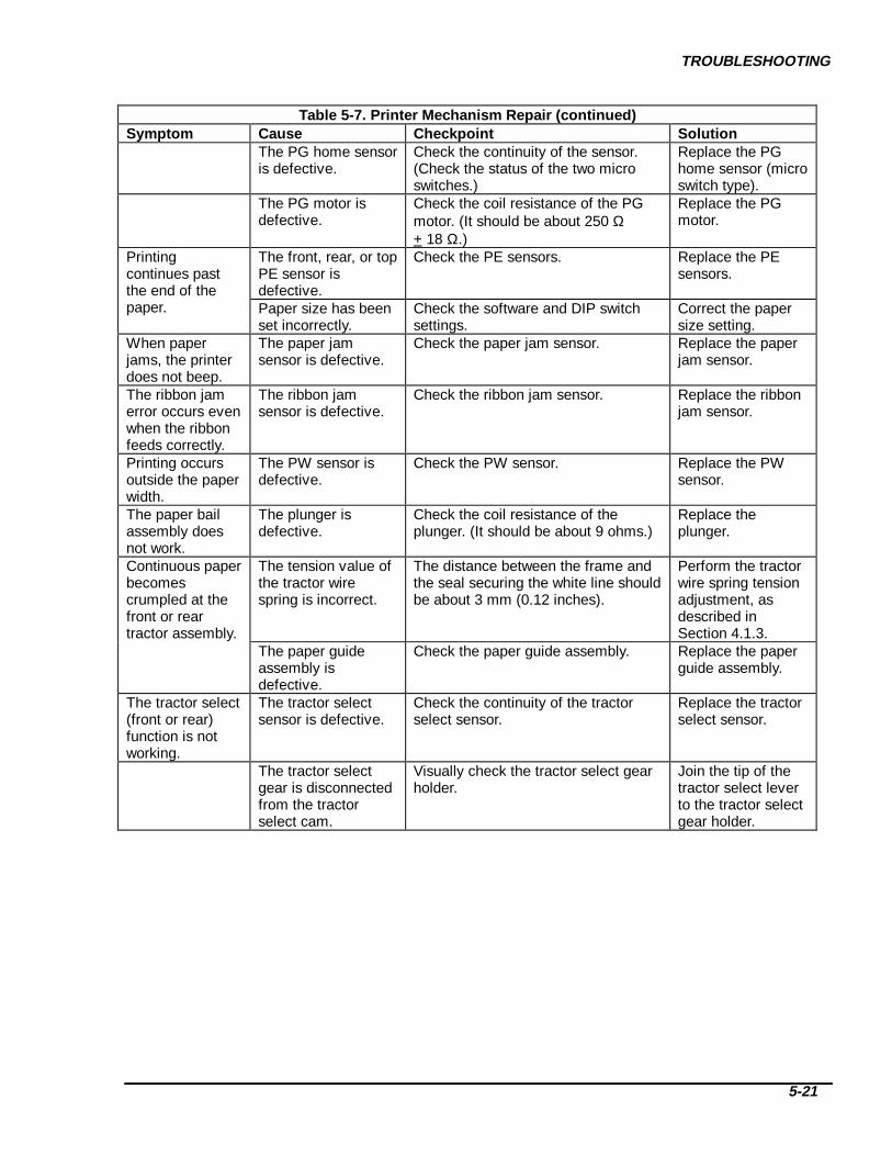
TROUBLESHOOTING
5-21
Table 5-7. Printer Mechanism Repair (continued)Symptom Cause Checkpoint Solution
The PG home sensoris defective.
Check the continuity of the sensor.(Check the status of the two microswitches.)
Replace the PGhome sensor (microswitch type).
The PG motor isdefective.
Check the coil resistance of the PGmotor. (It should be about 250 Ω+ 18 Ω.)
Replace the PGmotor.
The front, rear, or topPE sensor isdefective.
Check the PE sensors. Replace the PEsensors.
Printingcontinues pastthe end of thepaper. Paper size has been
set incorrectly.Check the software and DIP switchsettings.
Correct the papersize setting.
When paperjams, the printerdoes not beep.
The paper jamsensor is defective.
Check the paper jam sensor. Replace the paperjam sensor.
The ribbon jamerror occurs evenwhen the ribbonfeeds correctly.
The ribbon jamsensor is defective.
Check the ribbon jam sensor. Replace the ribbonjam sensor.
Printing occursoutside the paperwidth.
The PW sensor isdefective.
Check the PW sensor. Replace the PWsensor.
The paper bailassembly doesnot work.
The plunger isdefective.
Check the coil resistance of theplunger. (It should be about 9 ohms.)
Replace theplunger.
The tension value ofthe tractor wirespring is incorrect.
The distance between the frame andthe seal securing the white line shouldbe about 3 mm (0.12 inches).
Perform the tractorwire spring tensionadjustment, asdescribed inSection 4.1.3.
Continuous paperbecomescrumpled at thefront or reartractor assembly.
The paper guideassembly isdefective.
Check the paper guide assembly. Replace the paperguide assembly.
The tractor select(front or rear)function is notworking.
The tractor selectsensor is defective.
Check the continuity of the tractorselect sensor.
Replace the tractorselect sensor.
The tractor selectgear is disconnectedfrom the tractorselect cam.
Visually check the tractor select gearholder.
Join the tip of thetractor select leverto the tractor selectgear holder.

DFX-8500
5-22

CHAPTER 6MAINTENENCE
6.1 PREVENTIVE MAINTENANCE ___________________________________________________1
6.2 LUBRICATION AND ADHESIVE APPLICATION ____________________________________1

MAINTENANCE
6-1
6.1 PREVENTIVE MAINTENANCETo keep the printer in good condition, regularly clean the case exterior with a soft cloth and some alcoholand vacuum the mechanism's interior to remove dust and paper debris. After servicing the printer, makesure it is adequately lubricated, as described in Section 6.2. Before returning the printer to the customer,make sure the springs and paper feed rollers operate properly.
Unplug the printer before performing maintenance. Do not use thinner, trichloroethylene, or ketone-based solvents on the plastic components of the printer.
Note: The carriage encoder belt should be cleaned periodically. Clean it when the printer is returned forservice.
6.2 LUBRICATION AND ADHESIVE APPLICATIONEPSON recommends that the printer be lubricated at the points illustrated in Figures 6-2, 6-3, and 6-4 usingEPSON lubricants O2 and G26. These lubricants have been extensively tested and found to comply with theneeds of the printer. See Table 6-1 for information on lubricants O2 and G26. Table 6-2 lists the appropriatelubricant for each lubrication point. Make sure the parts are clean before applying lubricant. Avoid applyingtoo much lubricant, this may damage surrounding parts.
Adhesive application is necessary at the points indicated in Table 6-3 when parts are disassembled orreplaced. EPSON recommends Neji Lock #2 (G) adhesive be applied to the points illustrated in Figures 6-2,6-3, and 6-4. Avoid adhesive overflow onto related parts.
Table 6-1. Recommended LubricantsType Name Quantity Part No. Availa bilityGrease G26 40 g B702600001 EOil O2 40 cc B710200001 EAdhesive Neji Lock #2 (G) 1000 g B730200200 ENote: E = EPSON exclusive product (not commercially available)
CAUTION

DFX-8500
6-2
Table 6-2. Lubrication Points
LubricationPoint
See Figure: Description Lubricant
1 6-3 Carriage oil pad ring (on both left and right sides of carriage) O22 6-3 Carriage oil pad (under the carriage head cable holder), O23 6-3 Hole holding the tip of the rear carriage guide shaft (in both
left and right frames)G26
4 6-3 Both edges of the rear carriage guide shaft G265 6-3 Parallelism adjustment lever (where it contacts the rear
carriage guide shaft)G26
6 6-4 Rear carriage shaft holding lever (where it contacts the rearcarriage guide shaft)
G26
7 6-3 Carriage guide shaft (on the front and rear shafts) G268 6-4 Platen roller shaft holder (where it contacts the platen roller) G269 6-4 Paper bail gear G2610 6-2 Shafts of paper feed gears (shafts on the left frame) G26,O211 6-2 Paper feed gears (gears on the left frame) G2612 6-2 Tension pulley (pulley shaft and hook for the tension pulley
spring)G26
13 6-3 Fulcrum point for the paper bail shaft and plunger G2614 6-4 Platen gap motor pinion G2615 6-3 Carriage guide shaft gear G2616 6-3 Ribbon feed gears G2617 6-3 Tractor select cam G26
Table 6-3. Adhesive Application Points
AdhesionPoint
See Figure: Description Adhesive
(25) 6-3 Tractor tension wire Neji Lock #2 (G)
Figure 6-1. Co rrect Adhesive A pplication

MAINTENANCE
6-3
Figure 6-2. Lubrication and Adhesion Points (1/3)

DFX-8500
6-4
Figure 6-3. Lubrication and Adhesion Points (2/3)

MAINTENANCE
6-5
Figure 6-4. Lubrication and Adhesion Points (3/3)

DFX-8500
6-6

APPENDIX
A.1 CONNECTOR PIN ASSIGNMENTS ____________________________________________A-1
A.2 COMPONENT LAYOUT DIAGRAMS __________________________________________A-10
A.3 CONNECTORS ON THE CONNECTOR JUNCTION BOARD _____________________A-16
A.4 PARTS LIST ________________________________________________________________A-17
A.5 EXPLODED DIAGRAMS_____________________________________________________A-20
A.6 CIRCUIT DIAGRAMS _______________________________________________________A-28

APPENDIX
A-1
A.1 CONNECTOR PIN ASSIGNMENTS
Figure A-1 illustrates the connections between the primary components. Table A-1 lists the connectors andpin assignments.
CN
1(3)
CN5(2)
CN
3(12
)C
N2(
6)C
N4(
8)
Fan
C204 PSB/PSE
CN
3(2)
CN
4(4)
CN
5(14
)C
N9(
7)
CN
1(30
)
CN2(20)
C204 DRV-B
CN
1(30
)
CN3(20)
CN2(8)
CN8(8)
CN6(6)
CN12(36)CN13(7)
IEEE1284
EIA-232D
CN11(36)
TYPE-B
CN
10(8
)CN7(12) CN14(50x2) CN16(7)
CN15(6)
CN2(7)
CN1(6)
C204 SUB
C204 Main
C204 DRV
CN
2(50
)
CN
3(6)
CN1(50x2)
Printer Mechanism
C204 PNL
CN1(7) CN2(7)
Cover Open Sensor
CR Encoder
Junction Board
Printhead
Paper CutterUnit
AC Input
Figure A-1. Cable Connections

DFX-8500
A-2
Table A-1. Board Connector Summary
Connector Connected to: No. of Pins DetailsC204 Main Board
CN1 Mechanism (Printhead) 30 pins Table A-2CN2 C204 DRV-B board 20 pins Table A-3CN3 Cover Open 2 pins Table A-4CN4 Mechanism (Carriage encoder) 4 pins Table A-5CN5 Panel unit 14 pins Table A-6CN6 C204 PSB/PSE board 6 pins Table A-7CN7 C204 PSB/PSE board 12 pins Table A-8CN8 C204 DRV-B board 8 pins Table A-9CN9 Optional paper cutter 7 pins Table A-10CN10 C204 PSB/PSE board 8 pins Table A-11CN11 Optional Type-B I/F card 36 pins Table A-12CN12 IEEE-1284 I/F 36 pins Tables 1-10 and 1-11CN13 EIA 232D I/F 7 pins Table 1-12CN14 C204 DRV board 50 pins × 2 Table A-13CN15 C204 SUB board 6 pins Table A-14CN16 C204 SUB board 7 pins Table A-15
C204 DRV BoardCN1 C204 Main board 50 pins × 2 Table A-13CN2 Printer mechanism 50 pins Table A-16CN3 C204 PSB/PSE board 6 pins Table A-17
C204 DRV-B BoardCN1 Mechanism (Printhead) 30 pins Table A-18CN2 C204 Main board 6 pins Table A-9CN3 C204 Main board 20 pins Table A-3
C204 PSB/PSE boardCN1 AC inlet 3 pins Table A-19CN2 C204 Main board 6 pins Table A-7CN3 C204 Main (CN7) and C204 DRV
(CN3) boards12 pins Tables A-8 and A-17
CN4 C204 Main board 8 pins Table A-11CN5 Cooling fan motor 2 pins Table A-20
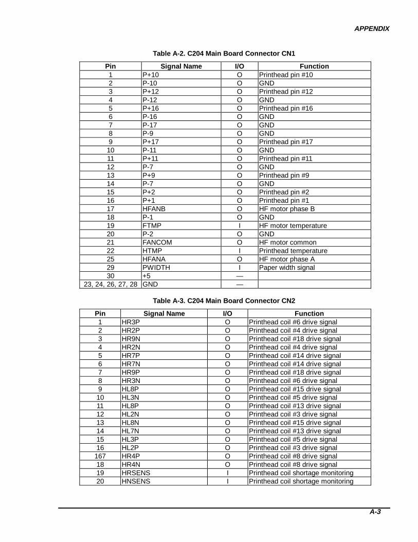
APPENDIX
A-3
Table A-2. C204 Main Board C onnector CN1
Pin Signal Name I/O Function1 P+10 O Printhead pin #102 P-10 O GND3 P+12 O Printhead pin #124 P-12 O GND5 P+16 O Printhead pin #166 P-16 O GND7 P-17 O GND8 P-9 O GND9 P+17 O Printhead pin #17
10 P-11 O GND11 P+11 O Printhead pin #1112 P-7 O GND13 P+9 O Printhead pin #914 P-7 O GND15 P+2 O Printhead pin #216 P+1 O Printhead pin #117 HFANB O HF motor phase B18 P-1 O GND19 FTMP I HF motor temperature20 P-2 O GND21 FANCOM O HF motor common22 HTMP I Printhead temperature25 HFANA O HF motor phase A29 PWIDTH I Paper width signal30 +5 —
23, 24, 26, 27, 28 GND —
Table A-3. C204 Main Board C onnector CN2
Pin Signal Name I/O Function1 HR3P O Printhead coil #6 drive signal2 HR2P O Printhead coil #4 drive signal3 HR9N O Printhead coil #18 drive signal4 HR2N O Printhead coil #4 drive signal5 HR7P O Printhead coil #14 drive signal6 HR7N O Printhead coil #14 drive signal7 HR9P O Printhead coil #18 drive signal8 HR3N O Printhead coil #6 drive signal9 HL8P O Printhead coil #15 drive signal10 HL3N O Printhead coil #5 drive signal11 HL8P O Printhead coil #13 drive signal12 HL2N O Printhead coil #3 drive signal13 HL8N O Printhead coil #15 drive signal14 HL7N O Printhead coil #13 drive signal15 HL3P O Printhead coil #5 drive signal16 HL2P O Printhead coil #3 drive signal
167 HR4P O Printhead coil #8 drive signal18 HR4N O Printhead coil #8 drive signal19 HRSENS I Printhead coil shortage monitoring20 HNSENS I Printhead coil shortage monitoring

DFX-8500
A-4
Table A-4. C204 Main Board C onnector CN3
Pin Signal Name I/O Function1 COPEN I Cover open status2 GND — —
Table A-5. C204 Main Board C onnector CN4
Pin Signal Name I/O Function1 GND —2 +5V —3 ENCB I CR encoder B phase pulse4 ENCA I CR encoder A phase pulse
Table A-6. C204 Main Board C onnector CN5
Pin Signal Name I/O Function1 LED_DATA O LED data2 LED_XLE O LED data latch3 LED_CLK O LED data clock5 LED_XOE O LED light enable6 BUZZER O Buzzer7 VCC — +5 VDC9 SW_INH O Switch data transfer inhibit9 SW_S/XL O Switch data shift/load select11 SW_DATA I Switch data13 SW_CLK O Switch data clock
4, 10, 12, 14 GND —
Table A-7. C204 Main Board C onnector CN6
Pin Signal Name I/O Function1, 2, 3 VP1 — +37 VDC4, 5, 6 GP1 — GND for VP1
Table A-8. C204 Main Board C onnector CN7
Pin Signal Name I/O Function1, 2, 3 VP2 — +37 VDC4, 5, 6 GP2 — GND for VP2
Table A-9. C204 Main Board C onnector CN8
Pin Signal Name I/O Function8, 7, 6 VP1 — +37 VDC5, 4, 3 GP1 — GND for VP1
1 VX — +5 VDC switched by reset status2 GND —
Table A-10. C204 Main Board C onnector CN9
Pin Signal Name I/O Function1 CUTON O Cut signal2 CUTDIR I Cut direction3 CUTTER I Paper cutter mount/dismount

APPENDIX
A-5
4 CUTHPI I Cutter home position5 +5V —6 GND —7 RF I Reverse point signal
Table A-11. C204 Main Board C onnector CN10
Pin Signal Name I/O Function1, 2 +5V I3, 4 GND O
5 DRERR O Printhead driver error signal6 /PD O Power down signal7 CL I Current limit signal8 SD I Power shutdown signal
Table A-12. C204 Main Board C onnector CN11
Pin Signal Name I/O Function1, 2, 3, 4, 5, 6 +5 —
7 BTXD O Transmit data8 XREADY O Ready9 BRXD I Receive data10 NC —11 BXRST O Reset signal12 INH O Inhibit signal output13 XCMDREQ I Command request signal14 XWRRDY I Write ready signal15 XRDREQ I Read request signal16 XWR O Write signal17 XRD O Read signal18 XCS O Chip select signal
19, 20, 21, 22, 23, 24 GND —25 A3 O Address bus 326 A2 O Address bus 227 A1 O Address bus 128 A0 O Address bus 029 D7 I/O Data bus 730 D6 I/O Data bus 631 D5 I/O Data bus 532 D4 I/O Data bus 433 D3 I/O Data bus 334 D2 I/O Data bus 235 D1 I/O Data bus 136 D0 I/O Data bus 0

DFX-8500
A-6
Table A-13. C204 Main Board C onnector CN14
Pin Signal Name I/O Function1 VP3 — +37 VDC
2, 3, 4 GND —5, 6, 7, 8 +5 —
9, 10 VX — +5 VDC switched by reset status11 FAN O HF control signal12 PLN O Plunger negative channel13 RFH/R O RF motor common14 RFC O RF motor C phase pulse15 RFA O RF motor A phase pulse16 PGD O PG motor D phase pulse17 PGB O PG motor B phase pulse18 CRINS I CR motor isolation resistance
monitoring19 CRI1 O CR motor current limit signal 120 CRCLM I CR motor current limit signal21 CRD O CR motor bridge D signal22 CRB O CR motor bridge B signal23 PFH/R O PF motor common24 PFC O PF motor C phase pulse25 PFA O PF motor A phase pulse
26, 27 GND —28 TR_SEL I Tractor select signal29 P_TRCT I Pull tractor mount/dismount30 P_JAM I Paper jam detection31 F_PE I Front paper end32 R_PE I Rear paper end33 T_PE I Top paper end34 PGENCB I PG encoder B signal35 PGENCA I PG encoder A signal36 PGHOME I PG home position37 RBJAM I Ribbon jam38 PLP O Plunger P channel39 RFD O RF motor bridge D signal40 RFB O RF motor bridge B signal41 PGH/R O PG motor common42 PGC O PG motor C phase pulse43 PGA O PG motor A phase pulse44 CRI2 O CR motor current limit signal 245 CRI0 O CR motor current limit signal 046 CRCLK O Clock pulse for CR motor driver47 CRC O CR motor bridge C signal48 CRA O CR motor bridge A signal49 PFD O PF motor bridge D signal50 PFB O PF motor bridge B signal

APPENDIX
A-7
Table A-14. C204 Main Board C onnector CN15
Pin Signal Name I/O Function1 DIP1 I DIP switch bank 1 status2 DIP2 I DIP switch bank 2 status3 DIP3 I DIP switch bank3 status4 DIP4 I DIP switch bank 4 status5 DIP5 I DIP switch bank 5 status6 DIPCNT1 O DIP switch select port 1
Table A-15. C204 Main Board C onnector CN16
Pin Signal Name I/O Function1 DIPCNT2 O DIP switch select port 22 DIPCNT3 O DIP switch select port 33 DIPCNT4 O DIP switch select port 44 DIPCNT5 O DIP switch select port 55 DIPCNT6 O DIP switch select port 66 DIPCNT7 O DIP switch select port 77 DIPCNT8 O DIP switch select port 8
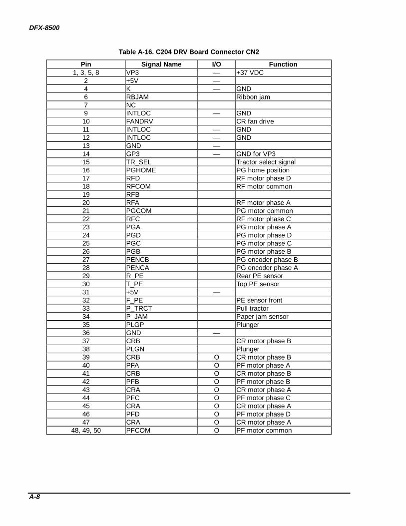
DFX-8500
A-8
Table A-16. C204 DRV Board C onnector CN2
Pin Signal Name I/O Function1, 3, 5, 8 VP3 — +37 VDC
2 +5V —4 K — GND6 RBJAM Ribbon jam7 NC9 INTLOC — GND10 FANDRV CR fan drive11 INTLOC — GND12 INTLOC — GND13 GND —14 GP3 — GND for VP315 TR_SEL Tractor select signal16 PGHOME PG home position17 RFD RF motor phase D18 RFCOM RF motor common19 RFB20 RFA RF motor phase A21 PGCOM PG motor common22 RFC RF motor phase C23 PGA PG motor phase A24 PGD PG motor phase D25 PGC PG motor phase C26 PGB PG motor phase B27 PENCB PG encoder phase B28 PENCA PG encoder phase A29 R_PE Rear PE sensor30 T_PE Top PE sensor31 +5V —32 F_PE PE sensor front33 P_TRCT Pull tractor34 P_JAM Paper jam sensor35 PLGP Plunger36 GND —37 CRB CR motor phase B38 PLGN Plunger39 CRB O CR motor phase B40 PFA O PF motor phase A41 CRB O CR motor phase B42 PFB O PF motor phase B43 CRA O CR motor phase A44 PFC O PF motor phase C45 CRA O CR motor phase A46 PFD O PF motor phase D47 CRA O CR motor phase A
48, 49, 50 PFCOM O PF motor common

APPENDIX
A-9
Table A-17. C204 DRV Board C onnector CN3
Pin Signal Name I/O Function1, 2, 3 VP3 — +37 VDC4, 5, 6 GP3 I GND for VP3
Table A-18. C204 DRV-B Board C onnector CN1
Pin Signal Name I/O Function1 P+6 O Printhead pin #62 P+4 O Printhead pin #43 P-18 O GND4 P-4 O GND5 P+14 O Printhead pin #146 P-14 O GND7 P+18 O Printhead pin #188 P-6 O GND9 P+15 O Printhead pin #1510 P-5 O GND11 P+13 O Printhead pin #1312 P-3 O GND13 P-15 O GND14 P-13 O GND15 P+5 O Printhead pin #516 P+3 O Printhead pin #317 P+8 O Printhead pin #818 P-8 O GND
19, 20 NC —
Table A-19. C204 PSB/PSE Board C onnector CN1
Pin Signal Name I/O Function1 L I AC input2 NC —3 N I AC input
Table A-20. C204 PSB/PSE Board C onnector CN5
Pin Signal Name I/O Function1 VP3 O2 /FANDR O Fan motor drive

DFX-8500
A-10
A.2 COMPONENT LAYOUT DIAGRAMS
Figure A-2. C204 Main Board Com ponent Layout (1)
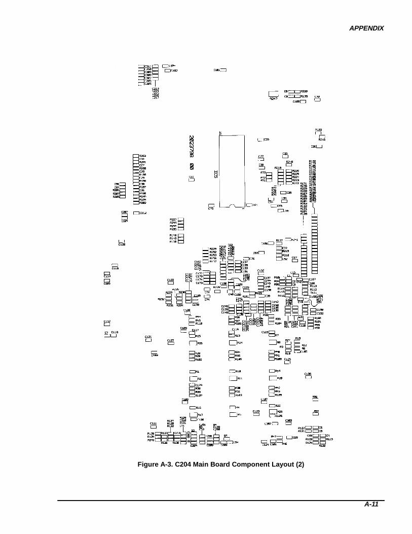
APPENDIX
A-11
Figure A-3. C204 Main Board Com ponent Layout (2)
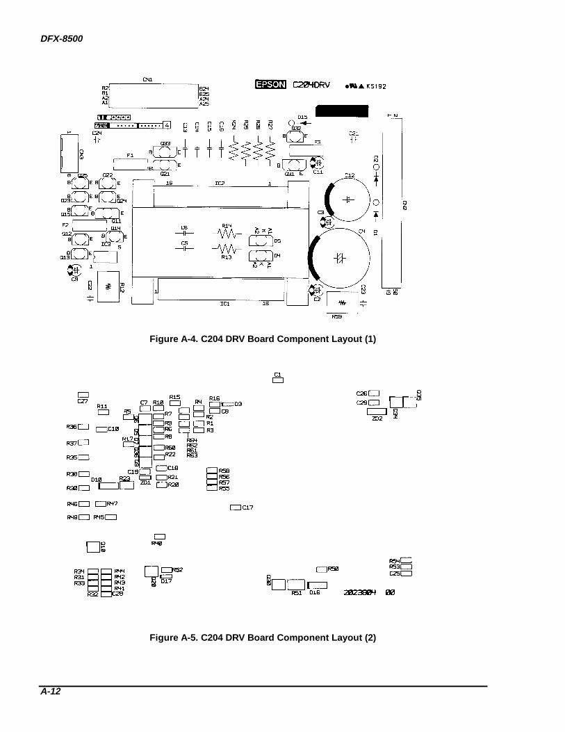
DFX-8500
A-12
Figure A-4. C204 DRV Board Com ponent Layout (1)
Figure A-5. C204 DRV Board Com ponent Layout (2)
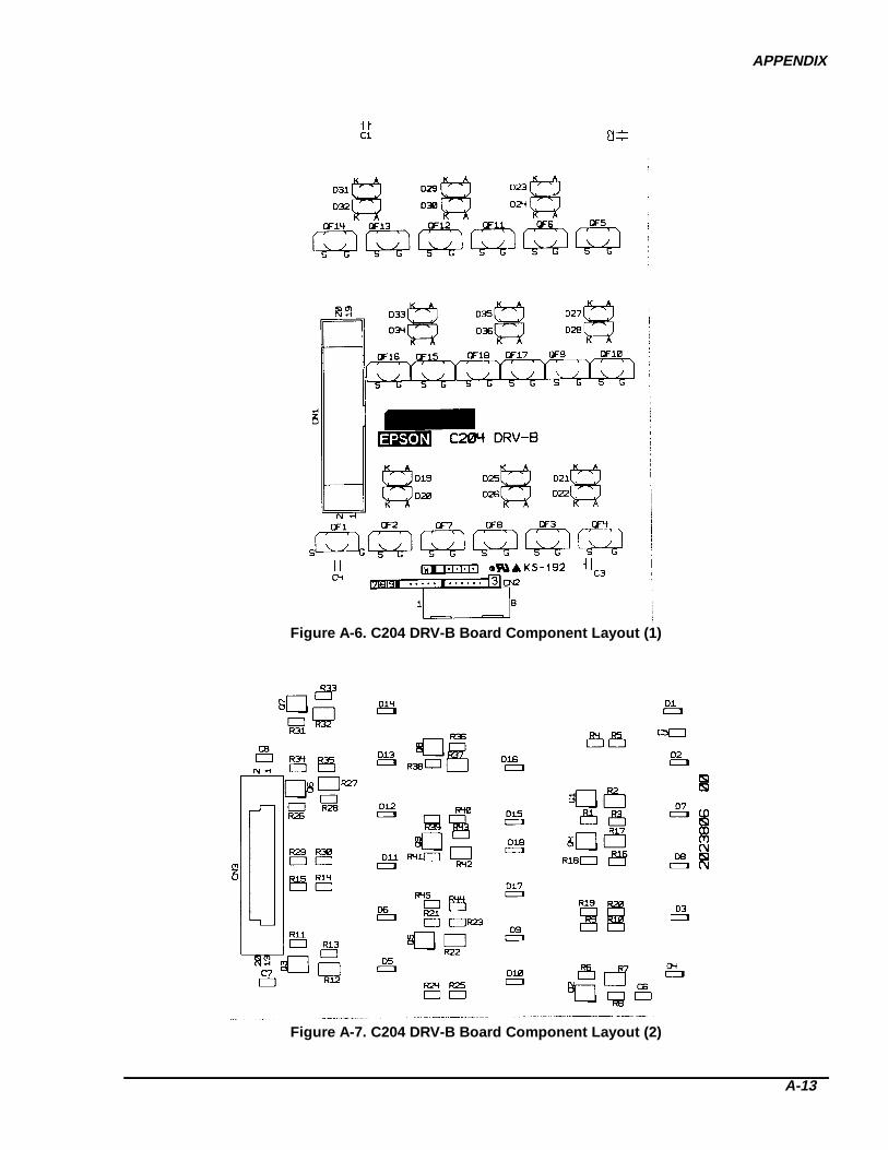
APPENDIX
A-13
Figure A-6. C204 DRV-B Board Com ponent Layout (1)
Figure A-7. C204 DRV-B Board Com ponent Layout (2)

DFX-8500
A-14
Figure A-8. C204 PSB Board Com ponent Layout
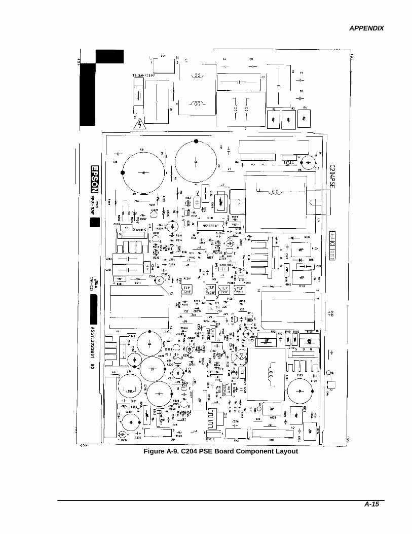
APPENDIX
A-15
Figure A-9. C204 PSE Board Com ponent Layout

DFX-8500
A-16
A.3 CONNECTORS ON THE CONNECTOR JUNCTION BOARDThe figure below illustrates the arrangement of connectors on the connector junction board.
RB WG YB BW W
W
W
W
R
R
WR
B
W
B
to Plunger
to O
ptio
n Pull T
ractor Senso
r
to Rear PE Sen
sor
to Top
PE Sens
or
to PG Enco
der
to PG M
otor
to TS/R
F M
otor
to F/R Tractor Select Senso
r
to PG HP Senso
r
to Pap
er Ja
m Senso
r
to Front PE Senso
r
t o C R M o t o r
t o P a p e r F e e d M o t o r
t o C R M o t o r F a n
t o O p t i o n C u t t e r P o w e r
t o F a n
t o R i b b o n J a m S e n s o r
t o I n t e r l o c k S w i t c h
R : R e d
W : W h i t e
G : G r a y
Y : Y e l l o w
B : B l a c kC o n n e c t o r C o l o r s
Figure A-10. Connectors on the Connector Junction Board
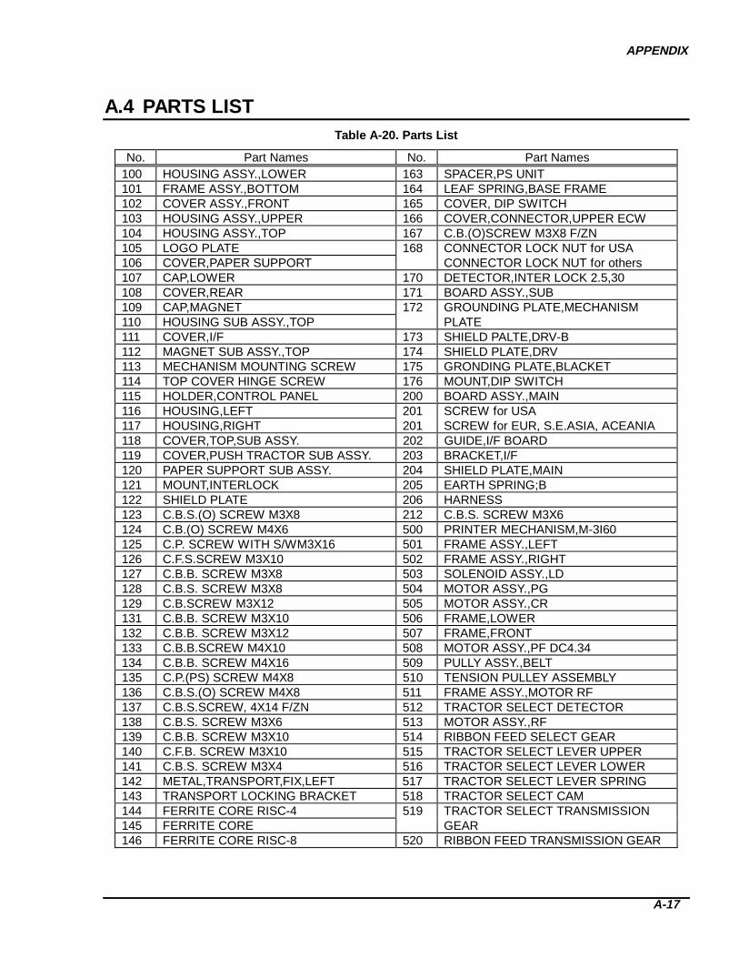
APPENDIX
A-17
A.4 PARTS LISTTable A-20. Parts List
No. Part Names No. Part Names100 HOUSING ASSY.,LOWER 163 SPACER,PS UNIT101 FRAME ASSY.,BOTTOM 164 LEAF SPRING,BASE FRAME102 COVER ASSY.,FRONT 165 COVER, DIP SWITCH103 HOUSING ASSY.,UPPER 166 COVER,CONNECTOR,UPPER ECW104 HOUSING ASSY.,TOP 167 C.B.(O)SCREW M3X8 F/ZN105 LOGO PLATE 168 CONNECTOR LOCK NUT for USA106 COVER,PAPER SUPPORT CONNECTOR LOCK NUT for others107 CAP,LOWER 170 DETECTOR,INTER LOCK 2.5,30108 COVER,REAR 171 BOARD ASSY.,SUB109 CAP,MAGNET 172 GROUNDING PLATE,MECHANISM110 HOUSING SUB ASSY.,TOP PLATE111 COVER,I/F 173 SHIELD PALTE,DRV-B112 MAGNET SUB ASSY.,TOP 174 SHIELD PLATE,DRV113 MECHANISM MOUNTING SCREW 175 GRONDING PLATE,BLACKET114 TOP COVER HINGE SCREW 176 MOUNT,DIP SWITCH115 HOLDER,CONTROL PANEL 200 BOARD ASSY.,MAIN116 HOUSING,LEFT 201 SCREW for USA117 HOUSING,RIGHT 201 SCREW for EUR, S.E.ASIA, ACEANIA118 COVER,TOP,SUB ASSY. 202 GUIDE,I/F BOARD119 COVER,PUSH TRACTOR SUB ASSY. 203 BRACKET,I/F120 PAPER SUPPORT SUB ASSY. 204 SHIELD PLATE,MAIN121 MOUNT,INTERLOCK 205 EARTH SPRING;B122 SHIELD PLATE 206 HARNESS123 C.B.S.(O) SCREW M3X8 212 C.B.S. SCREW M3X6124 C.B.(O) SCREW M4X6 500 PRINTER MECHANISM,M-3I60125 C.P. SCREW WITH S/WM3X16 501 FRAME ASSY.,LEFT126 C.F.S.SCREW M3X10 502 FRAME ASSY.,RIGHT127 C.B.B. SCREW M3X8 503 SOLENOID ASSY.,LD128 C.B.S. SCREW M3X8 504 MOTOR ASSY.,PG129 C.B.SCREW M3X12 505 MOTOR ASSY.,CR131 C.B.B. SCREW M3X10 506 FRAME,LOWER132 C.B.B. SCREW M3X12 507 FRAME,FRONT133 C.B.B.SCREW M4X10 508 MOTOR ASSY.,PF DC4.34134 C.B.B. SCREW M4X16 509 PULLY ASSY.,BELT135 C.P.(PS) SCREW M4X8 510 TENSION PULLEY ASSEMBLY136 C.B.S.(O) SCREW M4X8 511 FRAME ASSY.,MOTOR RF137 C.B.S.SCREW, 4X14 F/ZN 512 TRACTOR SELECT DETECTOR138 C.B.S. SCREW M3X6 513 MOTOR ASSY.,RF139 C.B.B. SCREW M3X10 514 RIBBON FEED SELECT GEAR140 C.F.B. SCREW M3X10 515 TRACTOR SELECT LEVER UPPER141 C.B.S. SCREW M3X4 516 TRACTOR SELECT LEVER LOWER142 METAL,TRANSPORT,FIX,LEFT 517 TRACTOR SELECT LEVER SPRING143 TRANSPORT LOCKING BRACKET 518 TRACTOR SELECT CAM144 FERRITE CORE RISC-4 519 TRACTOR SELECT TRANSMISSION145 FERRITE CORE GEAR146 FERRITE CORE RISC-8 520 RIBBON FEED TRANSMISSION GEAR
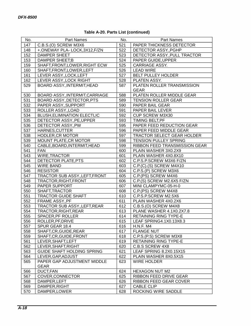
DFX-8500
A-18
Table A-20. Parts List (continued)
No. Part Names No. Part Names147 C.B.S.(O) SCREW M3X6 521 PAPER THICKNESS DETECTOR148 +.ONEWAY PLA- LOCK,3X12,F/ZN 522 DETECTOR ASSY.,PGHP152 DAMPER SHEET 523 DETECTOR ASSY.,PULL TRACTOR153 DAMPER SHEET;B 524 PAPER GUIDE,UPPER159 SHAFT,FRONT,LOWER,RIGHT ECW 525 CARRIAGE ASSY.160 SHAFT,FRONT,LOWER,LEFT 526 LEAD WIRE161 LEVER ASSY.,LOCK,LEFT 527 BELT PULLEY HOLDER162 LEVER ASSY.,LOCK RIGHT 528 PLATEN ASSY.529 BOARD ASSY.,INTERMIT,HEAD 587 PLATEN ROLLER TRANSMISSION
GEAR530 BOARD ASSY.,INTERMIT,CARRIAGE 588 PLATEN ROLLER MIDDLE GEAR531 BOARD ASSY.,DETECTOR,PTS 589 TENSION ROLLER GEAR532 PAPER ASSY.,SUPPORT 590 PAPER BAIL GEAR533 ROLLER ASSY.,LOAD 591 PAPER BAIL LEVER534 BLUSH,ELIMINATION ELECTLIC 592 CUP SCREW M3X30535 DETECTOR ASSY.,PE,UPPER 593 TIMING BELT,PF536 DETECTOR ASSY.,PW 595 PAPER FEED REDUCTION GEAR537 HARNES,CUTTER 596 PAPER FEED MIDDLE GEAR538 HODLER,CR MOTOR 597 TRACTOR SELECT GEAR HOLDER539 MOUNT PLATE,CR MOTOR 598 TENSION PULLEY SPRING540 CABLE,BOARD,INTERMIT,HEAD 599 RIBBON FEED TRANSMISSION GEAR541 FAN 600 PLAIN WASHER 3X0.2X9543 WIRE,TRACTOR 601 PLAIN WASHER 4X0.8X10544 DETECTOR PLATE,PTS 602 C.P.S.P.SCREW M3X6 F/ZN545 WIRE BAND 603 C.P.(C).(S) SCREW M4X10546 RESISTOR 604 C.P.S.(P) SCREW M3X6547 TRACTOR SUB ASSY.,LEFT,FRONT 605 C.P.(PS) SCREW M4X6548 TRACTOR,RIGHT,FRONT 606 C.P.(S) SCREW M2.6X5 F/ZN549 PAPER SUPPORT 607 MINI CLAMPYMC-05-H-0550 SHAFT,TRACTOR 608 C.P.(PS) SCREW M4X8551 TRACTOR GUIDE SHAFT 610 C.P.S.P.SCREW M2.5X6552 FRAME ASSY.,PF 611 PLAIN WASHER 4X0.2X6553 TRACTOR SUB ASSY.,LEFT,REAR 612 C.B.S.(O) SCREW M4X8554 TRACTOR,RIGHT,REAR 613 PLANE WASHER 4.1X0.2X7.8555 SPACER,PF ROLLER 614 RETAINING RING TYPE-E556 ROLLER,PF,DRIVE 615 LEAF SPRING4.1X0.13X8.3557 SPUR GEAR 18.4 616 H.N.F. M4558 SHAFT,CR,GUIDE,REAR 617 FLANGE NUT559 SHAFT,CR,GUIDE,FRONT 618 C.P.S.(P.S) SCREW M3X8561 LEVER,SHAFT,LEFT 619 RETAINING RING TYPE-E562 LEVER,SHAFT,RIGHT 620 C.B.S SCREW 4X8563 GUIDE SHAFT HOLDING SPRING 621 LEAF SPRING 8.2X0.15X15564 LEVER,GAP,ADJUST 622 PLAIN WASHER 8X0.5X15565 PAPER GAP ADJUSTMENT MIDDLE
GEAR623 WIRE HOLDER
566 DUCT,FAN 624 HEXAGON NUT M2567 COVER,CONNECTOR 625 RIBBON FEED DRIVE GEAR568 DAMPER,LEFT 626 RIBBON FEED GEAR COVER569 DAMPER,RIGHT 627 CABLE CLIP570 DAMPER,LOWER 628 ROCKING WIRE SADDLE

APPENDIX
A-19
Table A-20. Parts List (continued)
No. Part Names No. Part Names571 OIL PAD COVER 629 C.P.(PS).SCREW M4X8572 OIL PAD RING 630 C.P.S.SCREW M2X10573 FLAME,CABLE,HEAD 632 C.P.S.(O) SCREW M3X6574 COVER,HEAD CABLE 633 C.P.S(P.S) SCREW,3X10,F/ZN575 SHAFT,FASTEN,HOLDER 634 METAL FITTINGS,FASTEN,SHAFT576 TIMING BELT,CR 635 C.P.O SCREW M4X5577 HOLDER,BELT FASTEN 637 PLAIN WASHER 2.5X0.5X7.5579 FRAME,PAPER GUIDE MOUNT 638 SHEET,DUST PROOF580 EXTENSION SPRING,1000 639 C.B.S. SCREW M3X6581 PAPER GUIDE,LOWER 640 C.B.S. SCREW M3X8582 SHEET,HEAD CABLE,PROTECT 641 C.B.S.SCREW M4X6584 PLATEN ROLLER GEAR 644 PLASTI RIVET585 PLATEN ROLLER SHAFT HOLDER 645 HOLDER,PLATEN,RIGHT586 PLATEN ROLLER REDUCTION GEAR 646 HOLDER,PLATEN,LEFT647 SPUR,GEAR,40 669 FAN,CR648 EXTENSION SPRING,320 671 RIBON MASK SUB ASSY.649 MOUNT PLATE WIRE,RIGHT 672 SPUR,GEAR,24650 MOUNT PLATE,WIRE,LEFT 673 MOUNT PLATE,DETECTOR,RJ651 EXTENSION SPRING,40 674 DETECTOR ASSY.,RJ0V,0A,652 SPUR GEAR,32 675 HARNESS,FAN653 C.P.S SCREW,2X14,F/ZN 676 PAPER GUIDE ASSY.,PJ DETECTOR654 HEXAGON NUT A 801 INDIVIDUAL CARTON FOR AMERICA655 HEXAGON NUT,B 901 INDIVIDUAL CARTON BOX FOR
EUROPE656 LEVER,TENSION,CANCEL 1001 INDIVIDUAL CARTON BOX FOR
PACIFIC RIM657 BUSH,8 1102 OUTER CARTON BOX658 BUSH,12 1203 PAD,PRINTER,UPPER660 RESISTOR 0OHM, 1304 SHEET,PRINTER661 C.B.S.(O) SCREW M4X8 1405 PAD,PRINTER,UNDER662 MOUNTING PLATE,FAN,CR 1506 SHEET A663 DOUBLE SIDE TAPE,20X10 1607 SHEET B664 SHAFT,FASTEN,DAMPER,LEFT 1708 JOINT665 CABLE,SHIELD 1809 JOINTHP-601666 BOARD ASSY.,INTERMIT,MECHANISM 1910 CARRIAGE FIXING PLATE667 SHEET,PROTECT,CABLE 2011 PAD,PAPER GUIDE668 COMPOSITION SCREW,FAN 2118 PLASTIC BAG50X70X
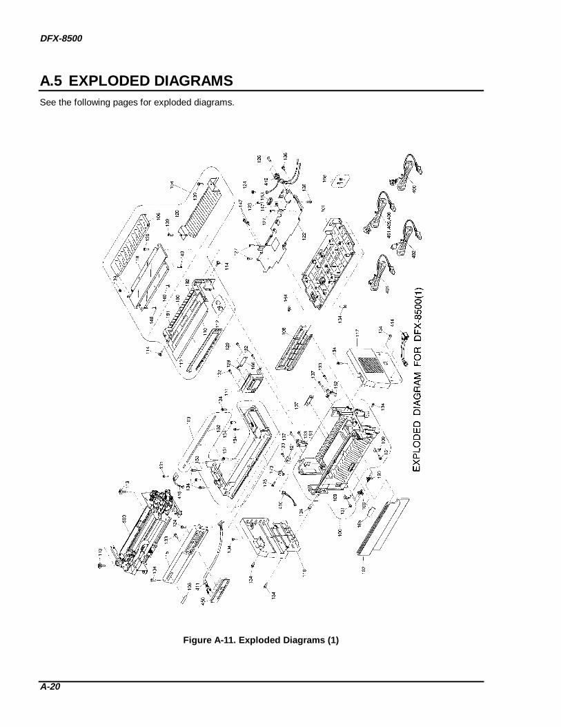
DFX-8500
A-20
A.5 EXPLODED DIAGRAMSSee the following pages for exploded diagrams.
Figure A-11. Exploded Diag rams (1)

APPENDIX
A-21
Figure A-12. Exploded Diag rams (2)
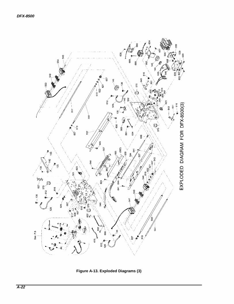
DFX-8500
A-22
Figure A-13. Exploded Diag rams (3)

APPENDIX
A-23
Figure A-14. Exploded Diag rams (4)

DFX-8500
A-24
Figure A-15. Exploded Diag rams (5)

APPENDIX
A-25
Figure A-16. Exploded Diag rams (6)
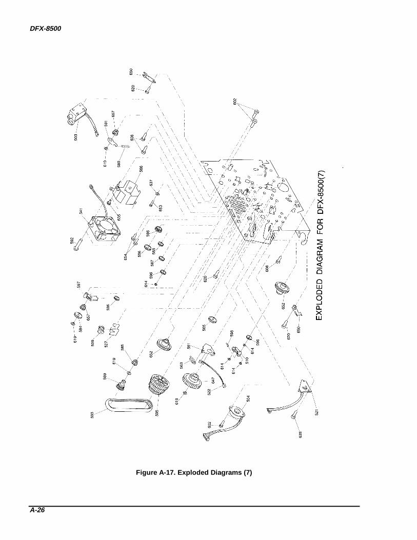
DFX-8500
A-26
Figure A-17. Exploded Diag rams (7)

APPENDIX
A-27
Figure A-18. Exploded Diag rams (8)

DFX-8500
A-28
A.6 CIRCUIT DIAGRAMSSee the following pages for these circuit diagrams:
C204 Main Board C204 DRV Board C204 DRV-B Board C204 PSB Board C204 PSE Board