Embed Size (px)
Citation preview
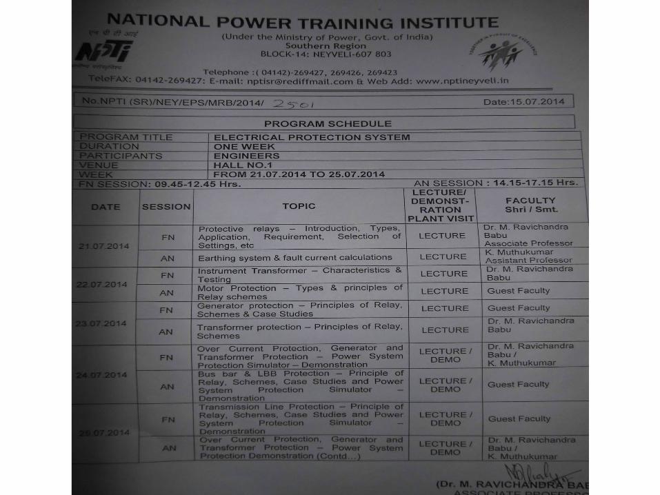
HARYANA VIDYUT PRASARAN NIGAM LIMITED
PRESENTATION OF TRAINING PROGRAM ON
ELECTRICAL PROTECTION SYSTEMHELD AT NPTI, NEYVELI
DURING 21.7.2014 T0 25.07.2014
Presented By:
Er Manoj KumarSSE, 220 KV S/Stn, Dhurala.

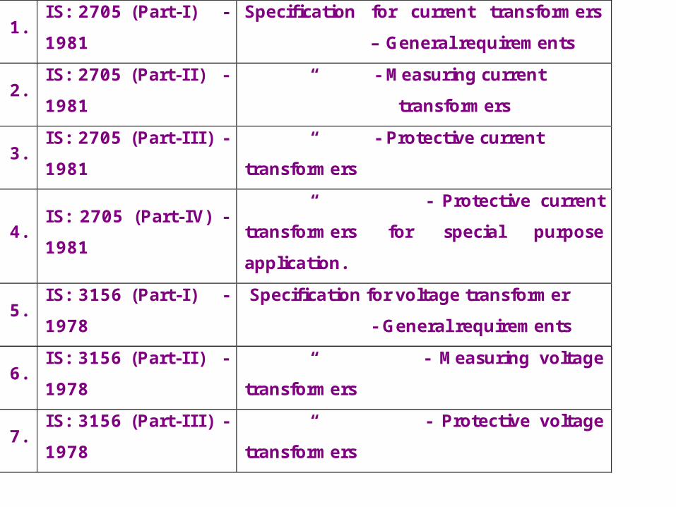
1. IS: 2705 (Part-I) - 1981
Specification for current transformers – General requirements
2. IS: 2705 (Part-II) - 1981
“ - Measuring current transformers
3. IS: 2705 (Part-III) - 1981
“ - Protective current transformers
4. IS: 2705 (Part-IV) - 1981
“ - Protective current transformers for special purpose application.
5. IS: 3156 (Part-I) - 1978
Specification for voltage transformer - General requirements
6. IS: 3156 (Part-II) - 1978
“ - Measuring voltage transformers
7. IS: 3156 (Part-III) - 1978
“ - Protective voltage transformers
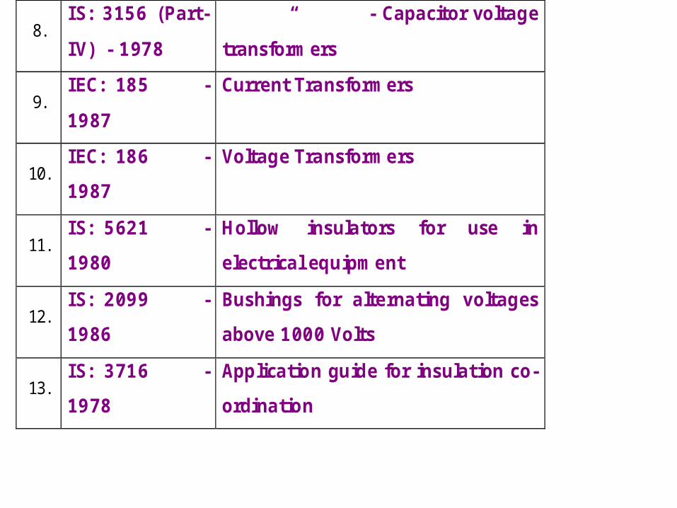
8. IS: 3156 (Part-IV) - 1978
“ - Capacitor voltage transformers
9. IEC: 185 - 1987
Current Transformers
10. IEC: 186 - 1987
Voltage Transformers
11. IS: 5621 - 1980
Hollow insulators for use in electrical equipment
12. IS: 2099 - 1986
Bushings for alternating voltages above 1000 Volts
13. IS: 3716 - 1978
Application guide for insulation co-ordination
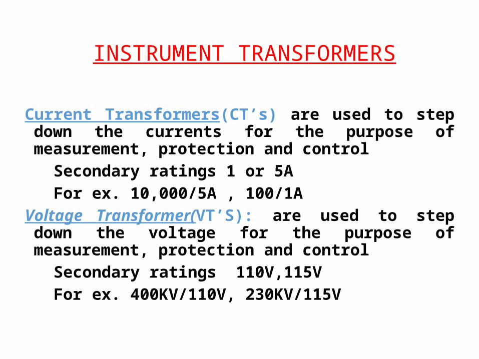
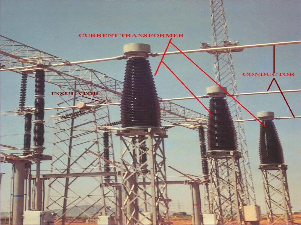
INSTRUMENT TRANSFORMERS
Current Transformers(CT’s) are used to step down the currents for the purpose of measurement, protection and control
Secondary ratings 1 or 5A For ex. 10,000/5A , 100/1AVoltage Transformer(VT’S): are used to step down the voltage
for the purpose of measurement, protection and control Secondary ratings 110V,115V For ex. 400KV/110V, 230KV/115V
Types of Current TransformerAccording to Construction: The use of one or the other is determined by the rated current of the apparatus and the rated burden required.•Bar Type: Suitable for large primary current because it can meet with the burden and accuracy requirements & at the same time can have high thermal & dynamic short circuit factors.•Wound type: Suitable for low primary current or where the burden & accuracy requirements are high.
According to Application Point:•Metering: The specific performance of the CT is to be maintained in the range normally 5% to 120% of the rated current. The CT cores should be such that it saturates at its ISF for safeguarding the instruments from getting damaged under faults.•Protection: The Main requirement is that its cores should not get saturated below its Accuracy Limiting Factor upto which the primary current should faithfully transformed to the secondary side, maintain the specified accuracy.•Protection CTs for Special Applications
Types of CTs
• Hair Pin Design• Eye Bolt Design• Live tank Design
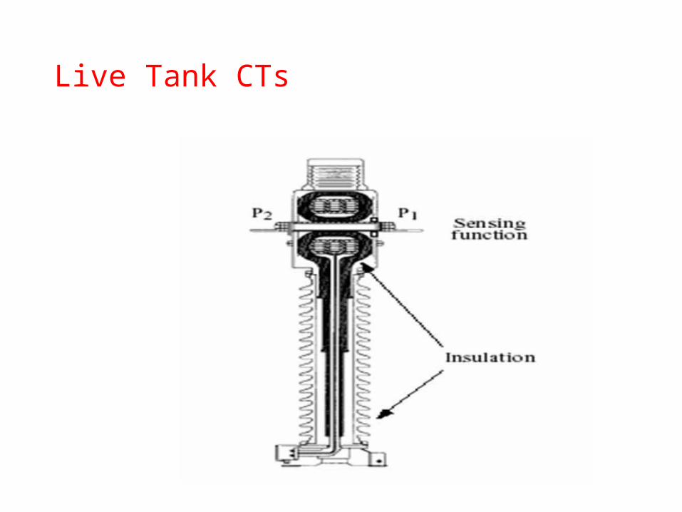
Live Tank CTs
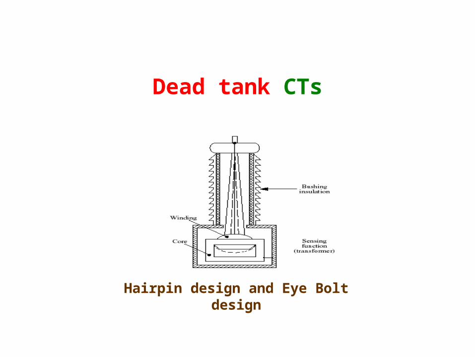
Dead tank CTs
Hairpin design and Eye Bolt design
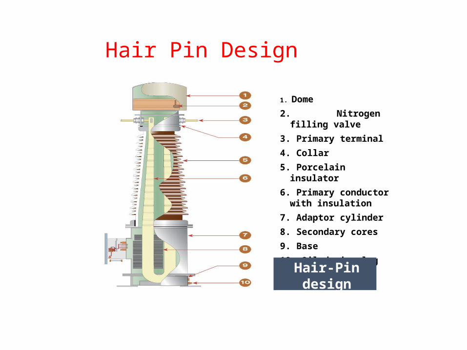
1. Dome2. Nitrogen filling valve 3. Primary terminal4. Collar5. Porcelain insulator6. Primary conductor with
insulation7. Adaptor cylinder8. Secondary cores9. Base10. Oil drain plug
Hair Pin Design
Hair-Pin design
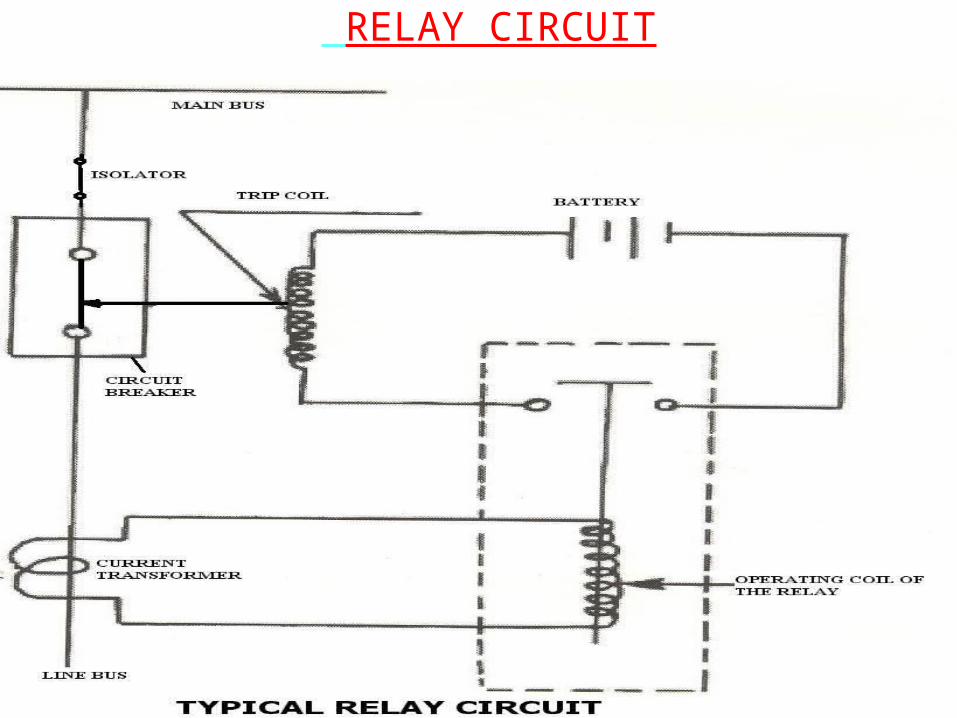
RELAY CIRCUIT
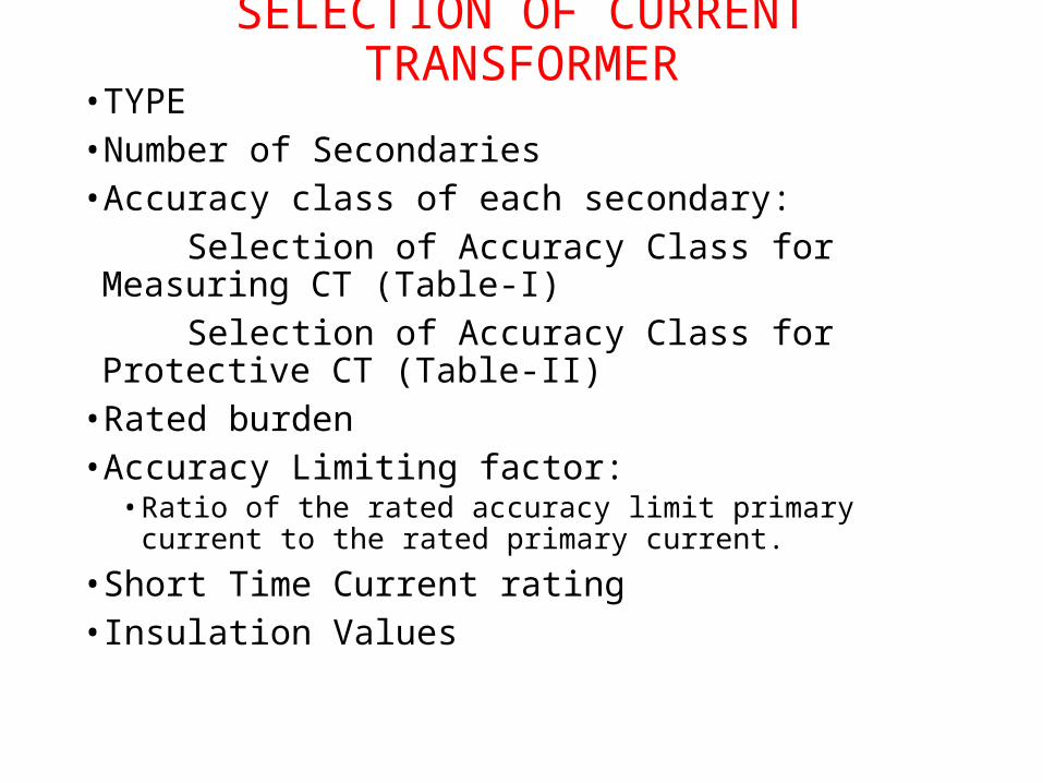
SELECTION OF CURRENT TRANSFORMER
• TYPE• Number of Secondaries• Accuracy class of each secondary: Selection of Accuracy Class for Measuring CT (Table-I) Selection of Accuracy Class for Protective CT (Table-II)• Rated burden• Accuracy Limiting factor:
• Ratio of the rated accuracy limit primary current to the rated primary current.
• Short Time Current rating• Insulation Values
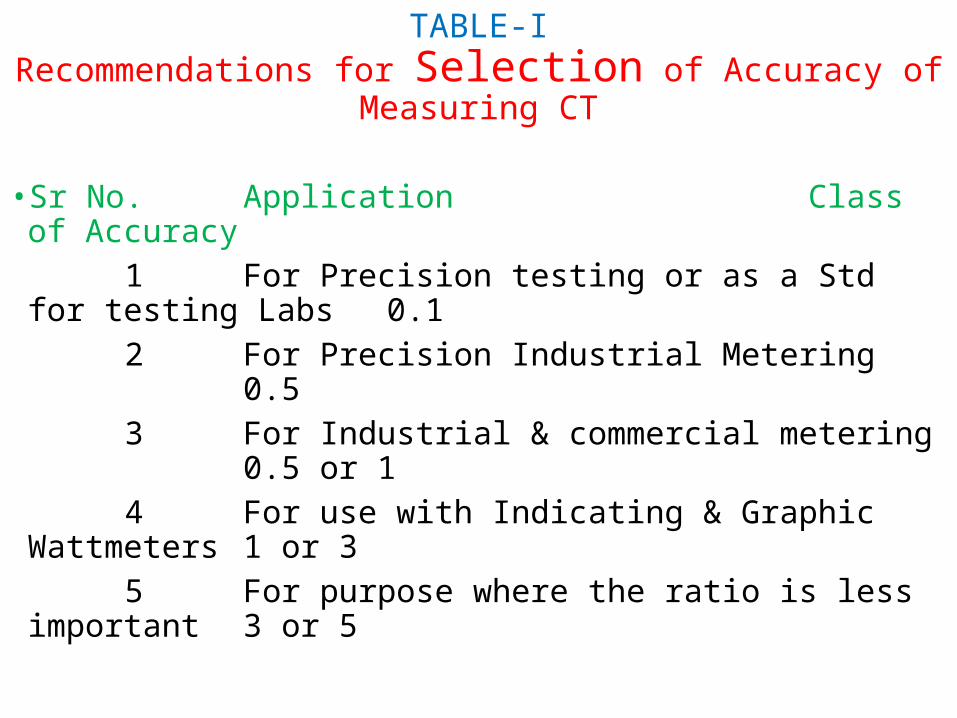
TABLE-IRecommendations for Selection of Accuracy of
Measuring CT
• Sr No. Application Class of Accuracy 1 For Precision testing or as a Std for testing Labs 0.1 2 For Precision Industrial Metering 0.5 3 For Industrial & commercial metering 0.5 or 1 4 For use with Indicating & Graphic Wattmeters 1 or 3 5 For purpose where the ratio is less important 3 or 5
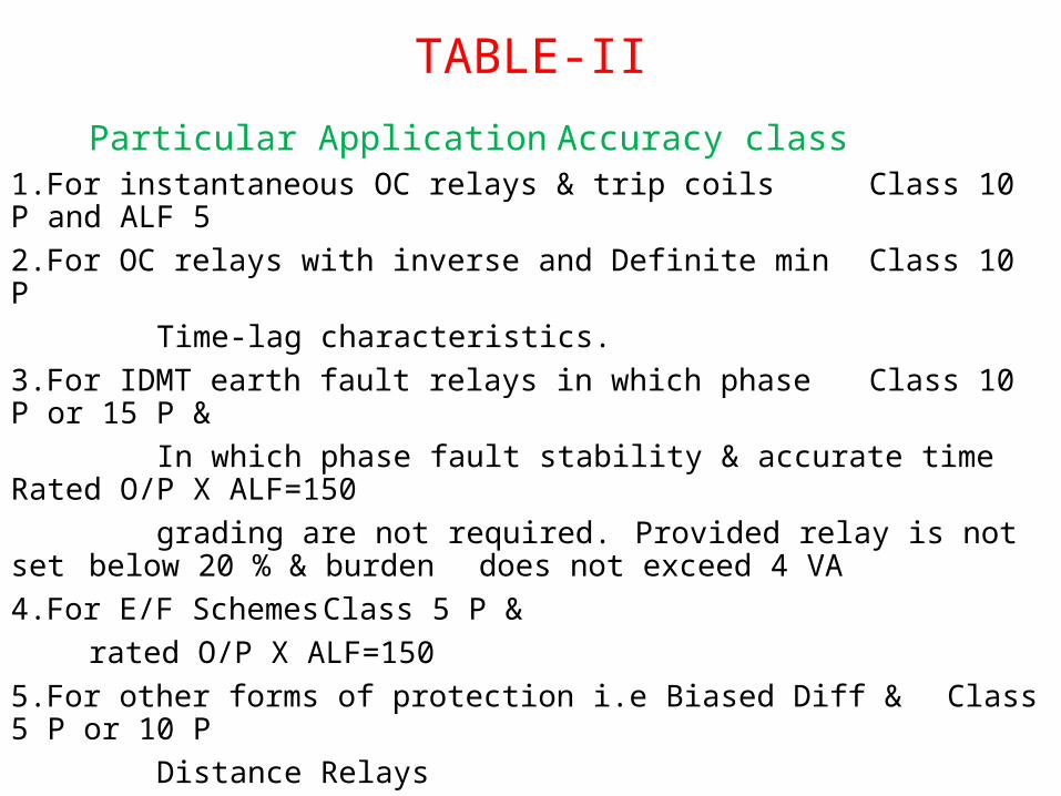
TABLE-IIParticular Application Accuracy class
1.For instantaneous OC relays & trip coils Class 10 P and ALF 52.For OC relays with inverse and Definite min Class 10 P Time-lag characteristics.3.For IDMT earth fault relays in which phase Class 10 P or 15 P & In which phase fault stability & accurate time Rated O/P X ALF=150 grading are not required. Provided relay is not set
below 20 % & burden does not exceed 4 VA
4.For E/F Schemes Class 5 P & rated O/P X ALF=150
5.For other forms of protection i.e Biased Diff & Class 5 P or 10 P Distance Relays
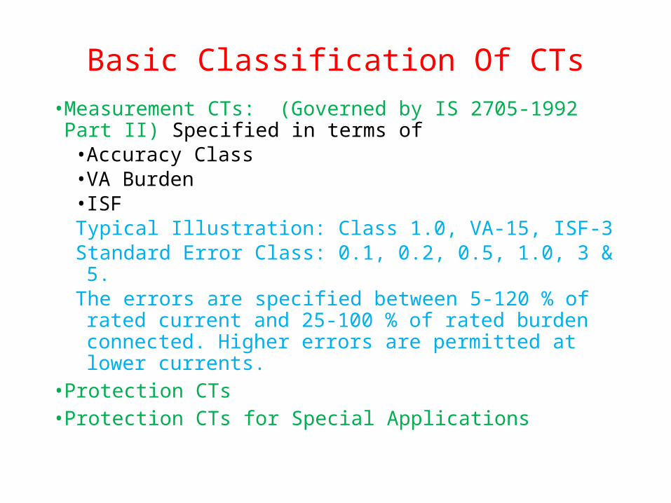
Basic Classification Of CTs• Measurement CTs: (Governed by IS 2705-1992 Part II)
Specified in terms of• Accuracy Class• VA Burden• ISFTypical Illustration: Class 1.0, VA-15, ISF-3Standard Error Class: 0.1, 0.2, 0.5, 1.0, 3 & 5.The errors are specified between 5-120 % of rated current
and 25-100 % of rated burden connected. Higher errors are permitted at lower currents.
• Protection CTs• Protection CTs for Special Applications
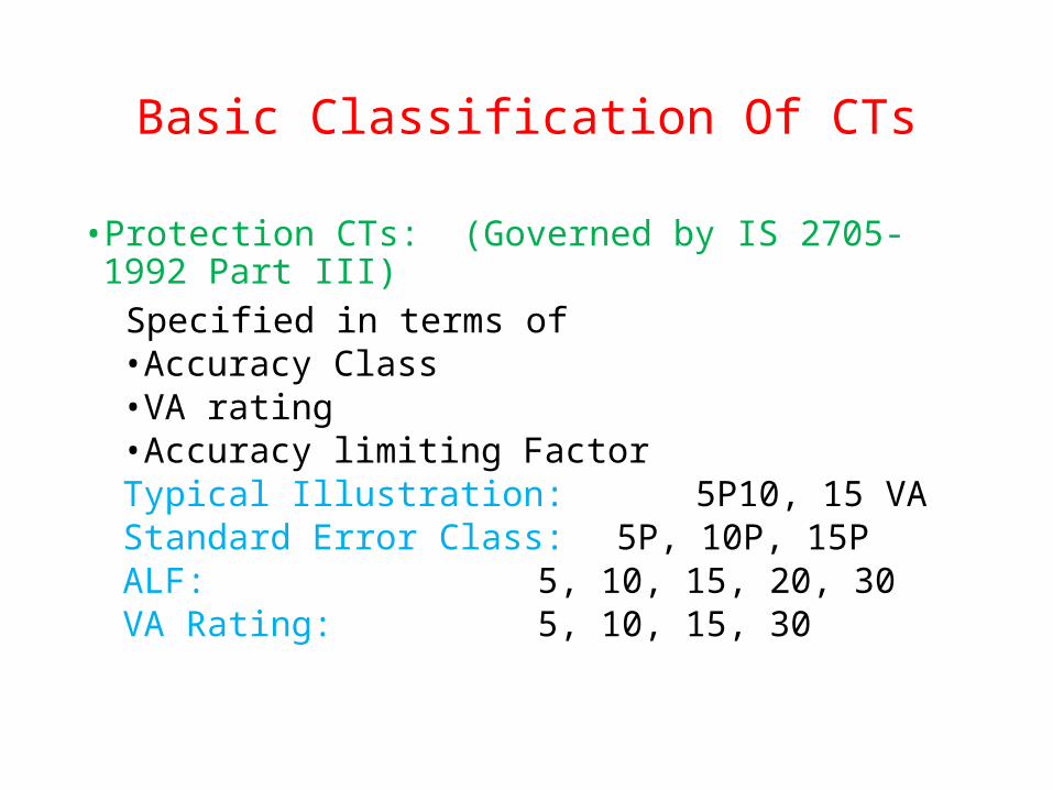
Basic Classification Of CTs
• Protection CTs: (Governed by IS 2705-1992 Part III) Specified in terms of
• Accuracy Class• VA rating• Accuracy limiting FactorTypical Illustration: 5P10, 15 VAStandard Error Class: 5P, 10P, 15PALF: 5, 10, 15, 20, 30VA Rating: 5, 10, 15, 30
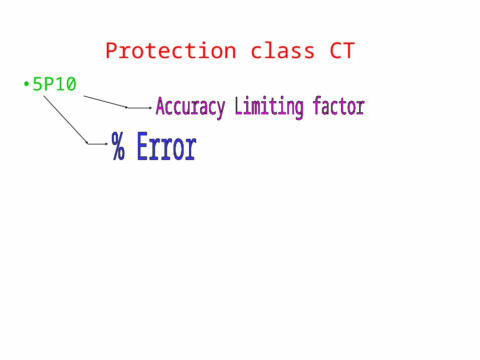
Protection class CT• 5P10
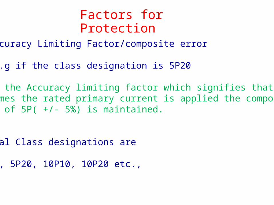
Factors for Protection
1. Accuracy Limiting Factor/composite error
For e.g if the class designation is 5P20
20 is the Accuracy limiting factor which signifies that when 20 times the rated primary current is applied the compositeerror of 5P( +/- 5%) is maintained.
Typical Class designations are
5P10, 5P20, 10P10, 10P20 etc.,
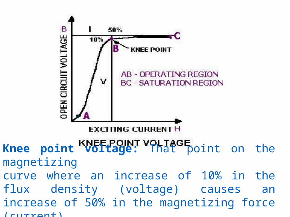
Knee point voltage: That point on the magnetizing curve where an increase of 10% in the flux density (voltage) causes an increase of 50% in the magnetizing force (current).
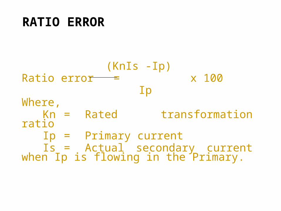
RATIO ERROR
(KnIs -Ip)Ratio error = x 100
IpWhere,
Kn = Rated transformation ratioIp = Primary currentIs = Actual secondary current when Ip is
flowing in the Primary.
PHASE DISPLACEMENT:
• Phase displacement is the difference between phases of primary and secondary current vectors. This is normally expressed in minutes. Phase displacement is said to be positive when the secondary current vector leads the primary current vector.
• Primary current – Exciting Current = Secondary Current when all the values are referred to either primary or secondary side. Hence the CT will have poor accuracy if the exciting current is large. To keep the errors low, the exciting current should be kept as low as possible. This can be achieved by:
Keeping the burden low Keeping the flux density low by providing large cross section of the core. Keeping the mean length of core as low as possible.
This is done by suitable design techniques for the primary coil insulation.
PROTECTIVE CURRENT TRANSFORMERS FOR SPECIAL PURPOSE APPLICATION:
• Protective current transformers used in association with special purpose application such as differential protection and distance protection schemes are designated as PS class CTs. For the PS class transformers, current ratio errors and phase angle errors are not specified, but instead, the turns ratio error, the minimum knee point voltage, maximum permissible exciting current and the maximum secondary winding resistance at 75o C are specified.
• There shall not be any turns correction for the PS class cores and the error in turns ratio shall not exceed + 0.25%.
The following are the various aspects associated with the fault current through the current transformers:
• Large error in ratio and phase angle.• Excessive heating• Development of mechanical forces high enough to
deform the winding and leads.• Generation of transient voltage rises.
• Saturation of core may be produced by the excessive symmetrical fault currents as well as by the lower magnitude of fault currents. Hence distortion of out put current will occur causing large errors.
• There are three sources of heating in CTs. Viz. magnetic, I2R losses in secondary and primary windings, I2R loss in primary winding under fault conditions will be significant. This cannot be dissipated so quickly by conduction or convection and hence the temperature of the winding will rise sharply. If the current density is so high, it may even cause to melt the winding.
• Mechanical forces may deform or displace the windings. The forces have the greatest value during the first amplitude. This occurs at a very short interval after the incidence of short circuit and thereafter declines rapidly towards its steady current value. This short duration for the maximum forces will have an impulsive or hammer effect.
Reasons of CT Failures• Moisture entry into solid insulation• Wrinkles in aluminium grading• Opening of secondary winding• Opening of tan delta point• High system parameters i.e. voltage & frequency,
switching over voltages, lighting over voltages.• Dielectric failure due to pre-mature ageing• Other dielectric failures due to improper wrapping
of paper, improper flux distribution etc.
Suggested Tests/Checks to Minimize The Failure of CT
Measurement of Tangent Delta and CapacitanceDGA MonitoringFuran AnalysisIR Measurement
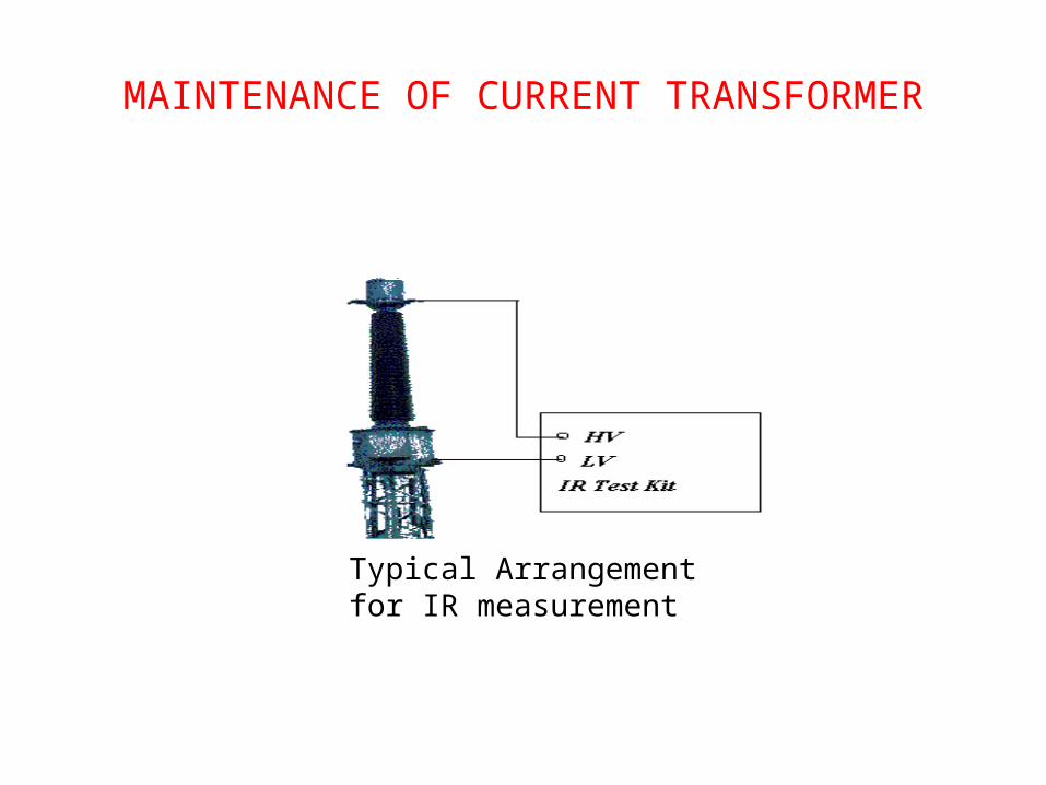
MAINTENANCE OF CURRENT TRANSFORMER
Typical Arrangement for IR measurement
TESTING OF CTS
TYCOMMISSIONING TESTROUTINE TESTSPECIAL TEST
•
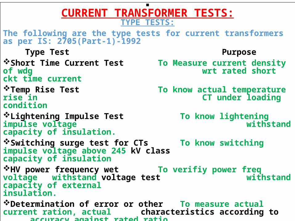
CURRENT TRANSFORMER TESTS:TYPE TESTS:
The following are the type tests for current transformers as per IS: 2705(Part-1)-1992
Type Test of terminal markings PurposeShort Time Current Test To Measure current density of wdg
wrt rated short ckt time currentTemp Rise Test To know actual temperature rise in
CT under loading conditionLightening Impulse Test To know lightening impulse voltage
withstand capacity of insulation.Switching surge test for CTs To know switching impulse voltage above 245 kV class capacity of insulationHV power frequency wet To verifiy power freq voltage withstand voltage test withstand capacity of external
insulation.Determination of error or other To measure actual current ration, actual characteristics according to accuracy against rated ratio. requirement of designation & To measure impedance of secondary ckt accuracy class
•
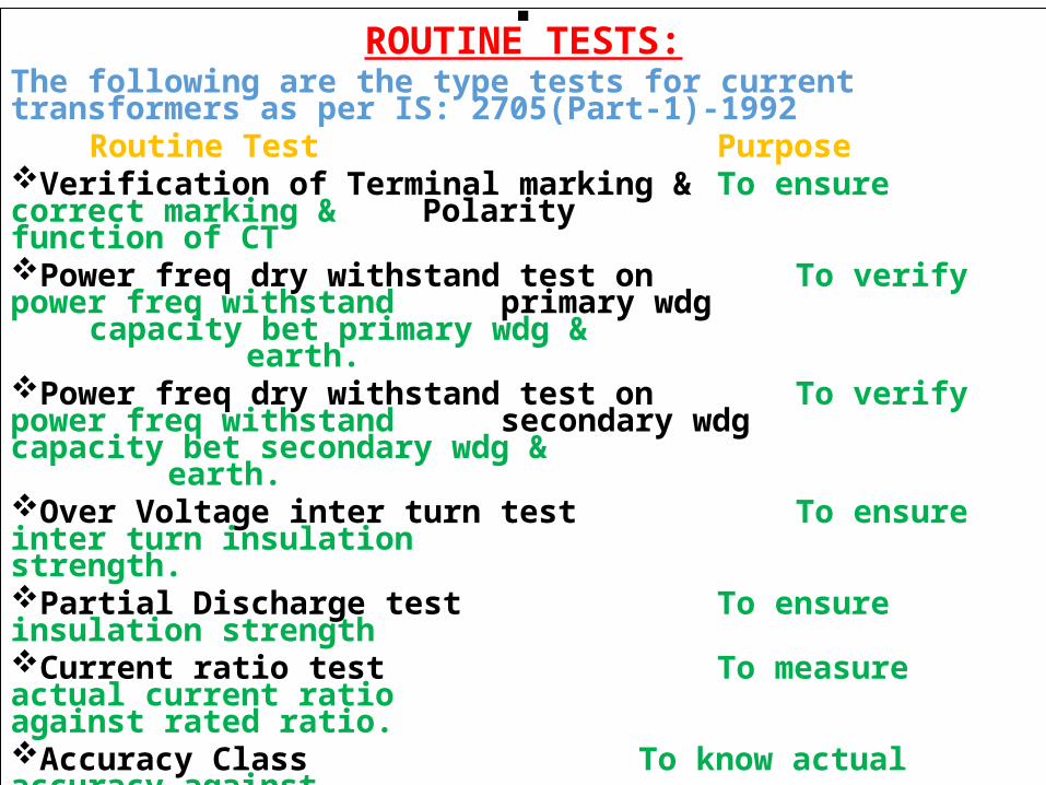
ROUTINE TESTS:The following are the type tests for current transformers as per IS: 2705(Part-1)-1992
Routine Test PurposeVerification of Terminal marking & To ensure correct marking & Polarity function of CTPower freq dry withstand test on To verify power freq withstand primary wdg capacity bet primary wdg &
earth.Power freq dry withstand test on To verify power freq withstand secondary wdg capacity bet secondary wdg &
earth.Over Voltage inter turn test To ensure inter turn insulation strength.Partial Discharge test To ensure insulation strengthCurrent ratio test To measure actual current ratio
against rated ratio.Accuracy Class To know actual accuracy against
rated.Burden To measure the impendence of the
secondary circuit.
SPECIAL TESTS
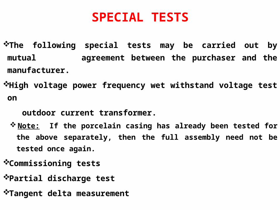
The following special tests may be carried out by mutual agreement between the purchaser and the manufacturer.
High voltage power frequency wet withstand voltage test on
outdoor current transformer.Note: If the porcelain casing has already been tested for the above
separately, then the full assembly need not be tested once again.
Commissioning tests
Partial discharge test
Tangent delta measurement
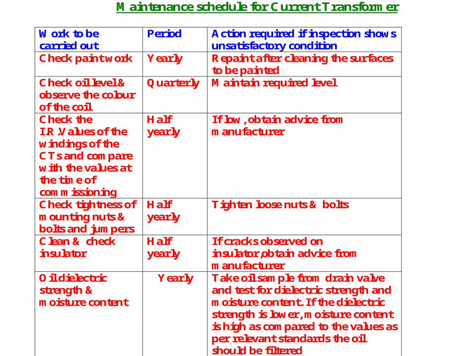
Maintenance schedule for Current Transformer
Work to be carried out
Period Action required if inspection shows unsatisfactory condition
Check paint work Yearly Repaint after cleaning the surfaces to be painted
Check oil level & observe the colour of the coil
Quarterly Maintain required level
Check the I.R.Values of the windings of the CTs and compare with the values at the time of commissioning
Half yearly
If low, obtain advice from manufacturer
Check tightness of mounting nuts & bolts and jumpers
Half yearly
Tighten loose nuts & bolts
Clean & check insulator
Half yearly
If cracks observed on insulator,obtain advice from manufacturer
Oil dielectric strength & moisture content
Yearly Take oil sample from drain valve and test for dielectric strength and moisture content. If the dielectric strength is lower, moisture content is high as compared to the values as per relevant standards the oil should be filtered
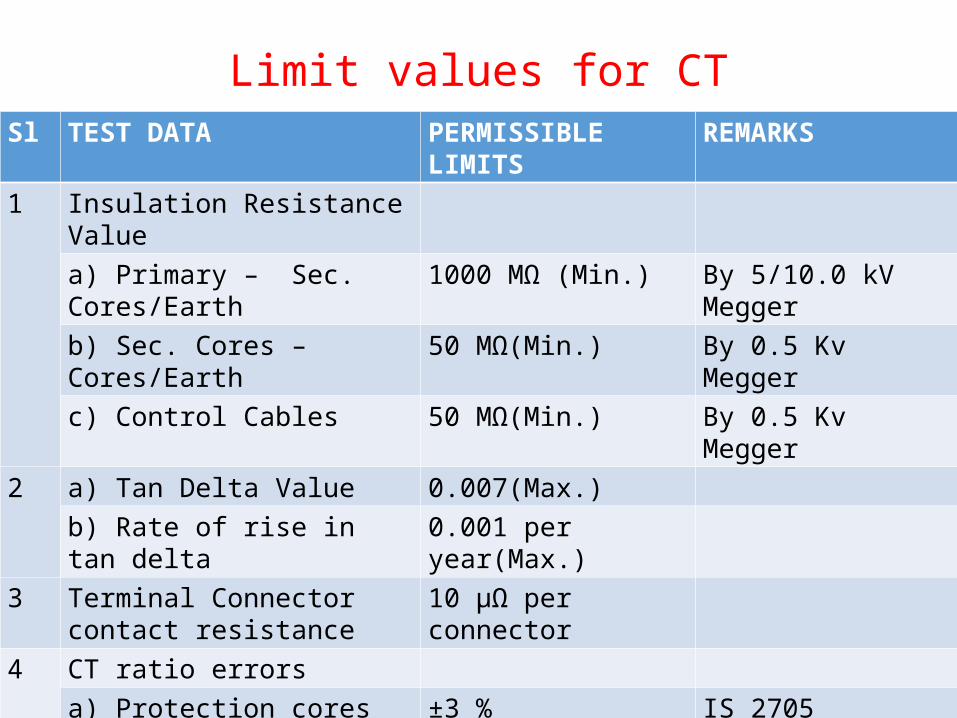
Limit values for CTSl TEST DATA PERMISSIBLE LIMITS REMARKS
1 Insulation Resistance Value
a) Primary – Sec. Cores/Earth 1000 MΩ (Min.) By 5/10.0 kV Megger
b) Sec. Cores – Cores/Earth 50 MΩ(Min.) By 0.5 Kv Megger
c) Control Cables 50 MΩ(Min.) By 0.5 Kv Megger2 a) Tan Delta Value 0.007(Max.)
b) Rate of rise in tan delta 0.001 per year(Max.)
3 Terminal Connector contact resistance
10 μΩ per connector
4 CT ratio errorsa) Protection cores ±3 % IS 2705b) Secondary cores ±1% IS 2705
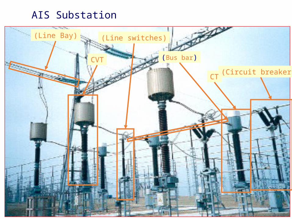
AIS Substation
(Circuit breakers)CT
(Bus bar)
(Line switches)
CVT
(Line Bay)
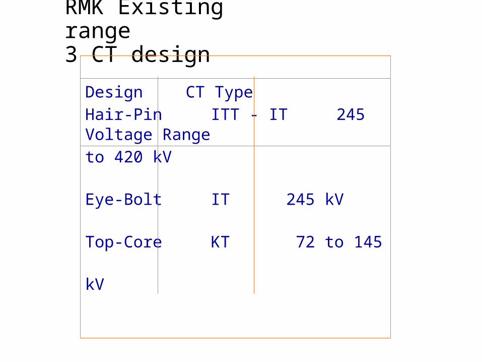
RMK Existing range3 CT design
Hair-Pin ITT - IT 245 to 420
kV
Eye-Bolt IT 245 kV
Top-Core KT 72 to 145 kV
Design CT Type Voltage
Range
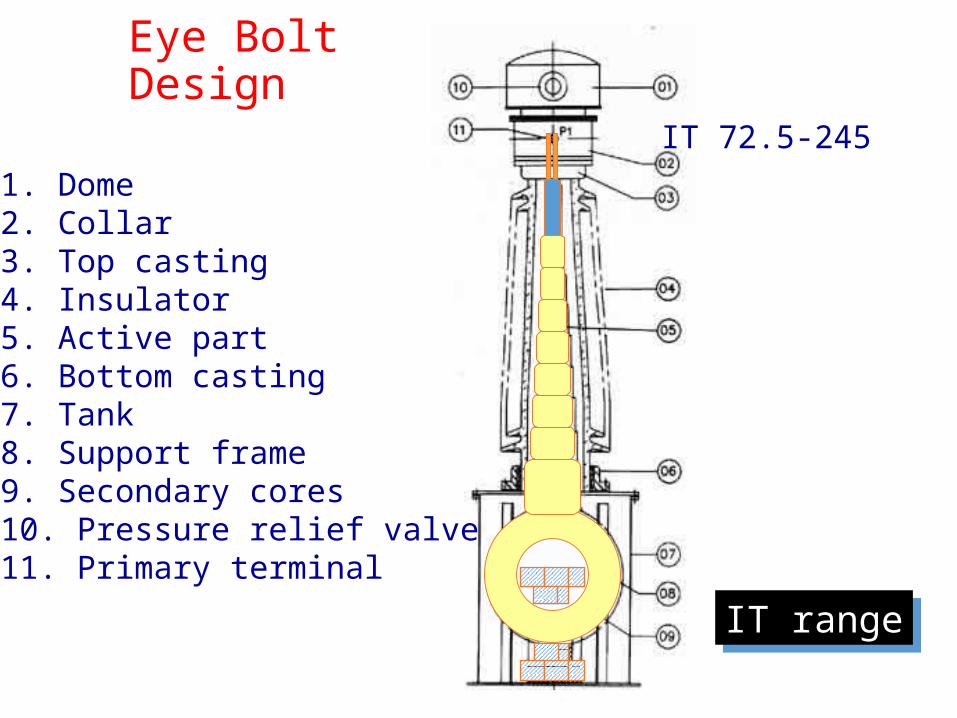
Eye Bolt Design
IT 72.5-2451. Dome2. Collar3. Top casting4. Insulator5. Active part6. Bottom casting7. Tank8. Support frame9. Secondary cores10. Pressure relief valve11. Primary terminal
IT range
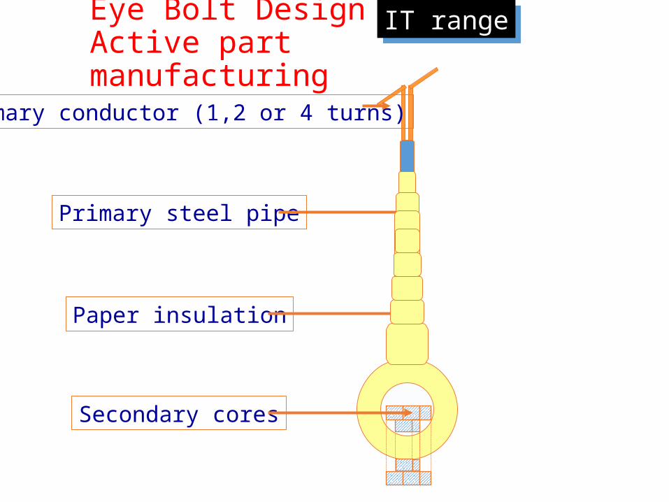
Primary conductor (1,2 or 4 turns)
Eye Bolt DesignActive part manufacturing
Primary steel pipe
Paper insulation
Secondary cores
IT range
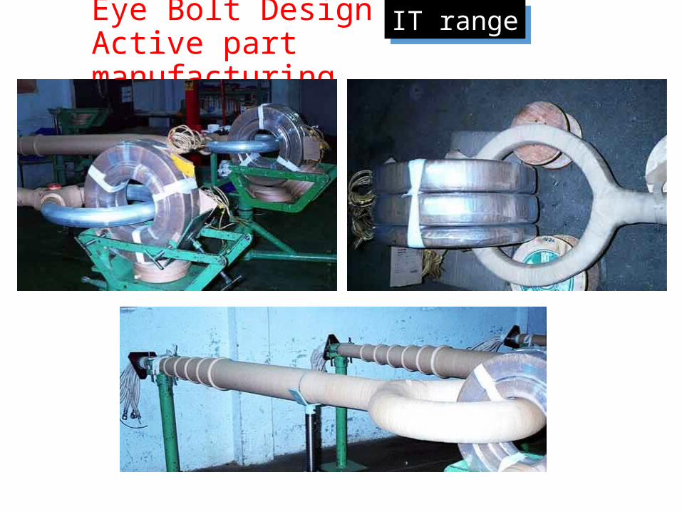
Eye Bolt DesignActive part manufacturing
IT range
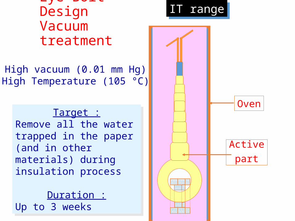
Oven
Eye Bolt DesignVacuum treatment
Target :Remove all the water trapped in the paper (and in other materials) during insulation process
Duration :Up to 3 weeks
High vacuum (0.01 mm Hg)High Temperature (105 °C)
Activepart
IT range
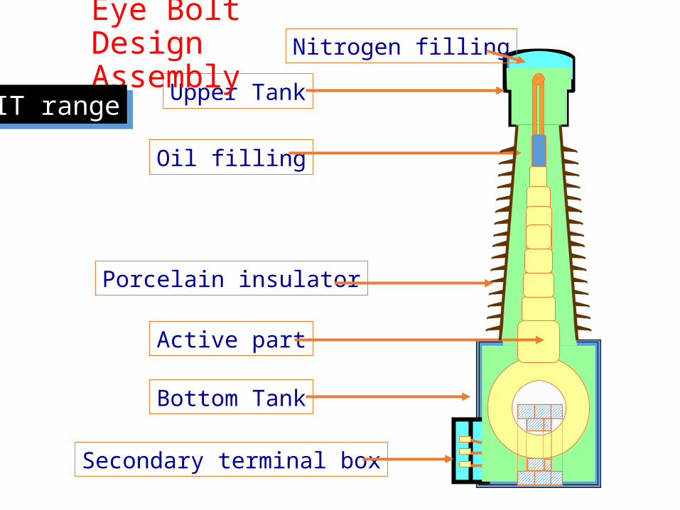
Upper TankNitrogen filling
Eye Bolt Design Assembly
Bottom Tank
Secondary terminal box
Oil filling
Active part
Porcelain insulator
IT range

Eye Bolt Design Assembly
Summary of Technical data :Rated voltage : 123 to 245 kVTechnolgy : Eye-BoltExpansion device : NitrogenPrimary reconnection : 1-2Rated primary current : 1200 Amp (1440 max)Short circuit current : 40 kA 1”
Total weight (kg)kV 72.5 145 245kg 700 750 1200
IT range
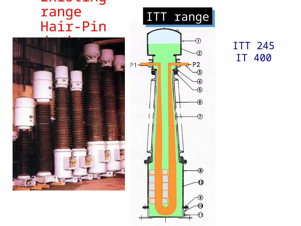
Existing rangeHair-Pin design
Tuyau
ITT 245IT 400
ITT range
Existing rangeHair-Pin design
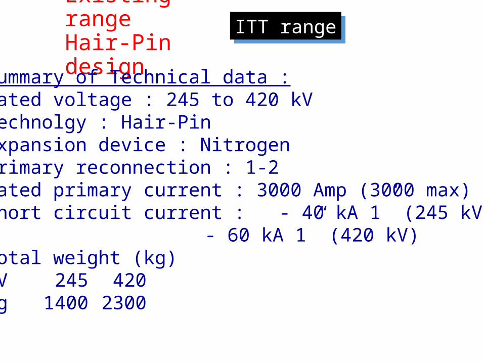
ITT range
Summary of Technical data :Rated voltage : 245 to 420 kVTechnolgy : Hair-PinExpansion device : NitrogenPrimary reconnection : 1-2Rated primary current : 3000 Amp (3000 max)Short circuit current : - 40 kA 1” (245 kV)
- 60 kA 1” (420 kV)Total weight (kg)kV 245 420kg 1400 2300
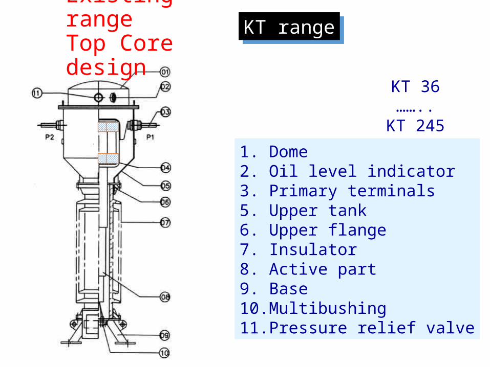
Existing rangeTop Core design
KT 36……..
KT 2451. Dome2. Oil level indicator3. Primary terminals5. Upper tank6. Upper flange7. Insulator8. Active part9. Base10.Multibushing11.Pressure relief valve
KT range
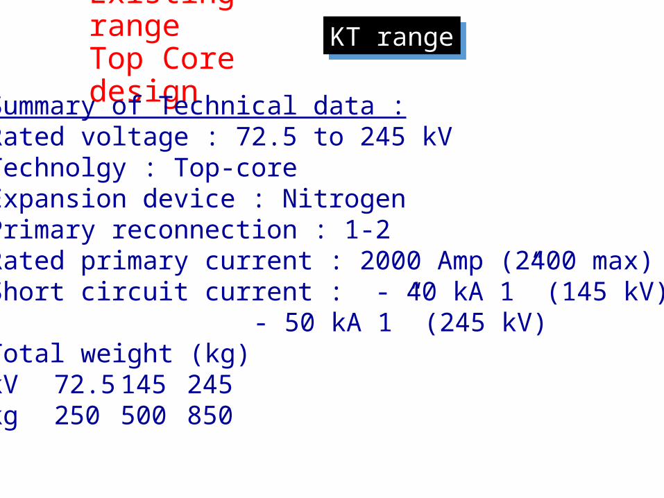
Existing rangeTop Core design
KT range
Summary of Technical data :Rated voltage : 72.5 to 245 kVTechnolgy : Top-coreExpansion device : NitrogenPrimary reconnection : 1-2Rated primary current : 2000 Amp (2400 max)Short circuit current : - 40 kA 1” (145 kV)
- 50 kA 1” (245 kV)Total weight (kg)kV 72.5 145 245kg 250 500 850

Factors for Protection
Parameters
1. ALF ( accuracy limiting factor)
2. Composite error
OVER CURRENT AND EARTH FAULT PROTECTION
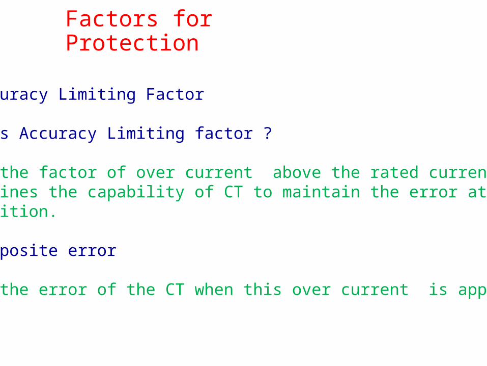
Factors for Protection
1. Accuracy Limiting Factor
What is Accuracy Limiting factor ?
It is the factor of over current above the rated current which determines the capability of CT to maintain the error at such a condition.
2. Composite error
It is the error of the CT when this over current is applied.
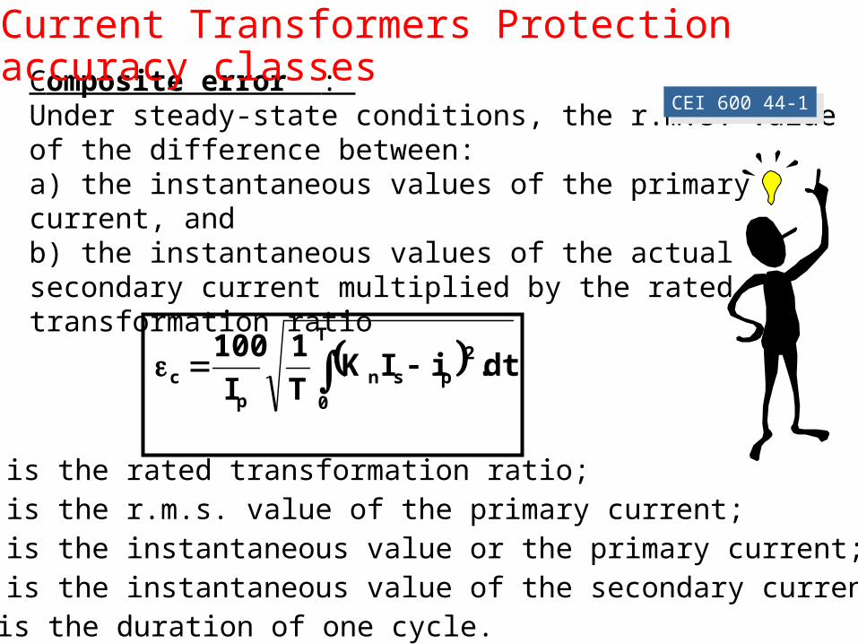
Composite error : Under steady-state conditions, the r.m.s. value of the difference between:a) the instantaneous values of the primary current, andb) the instantaneous values of the actual secondary current multiplied by the rated transformation ratio
CEI 600 44-1
T
0
2psn
pc dt.iIK
T1
I100
Current Transformers Protection accuracy classes
Kn is the rated transformation ratio;Ip is the r.m.s. value of the primary current;ip is the instantaneous value or the primary current;is is the instantaneous value of the secondary current;T is the duration of one cycle.
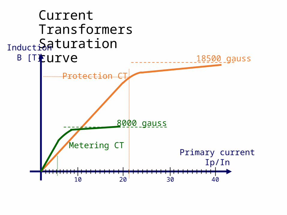
Current TransformersSaturation curve
10 20 30 40
InductionB [T]
Primary currentIp/In
Protection CT18500 gauss
Metering CT
8000 gauss
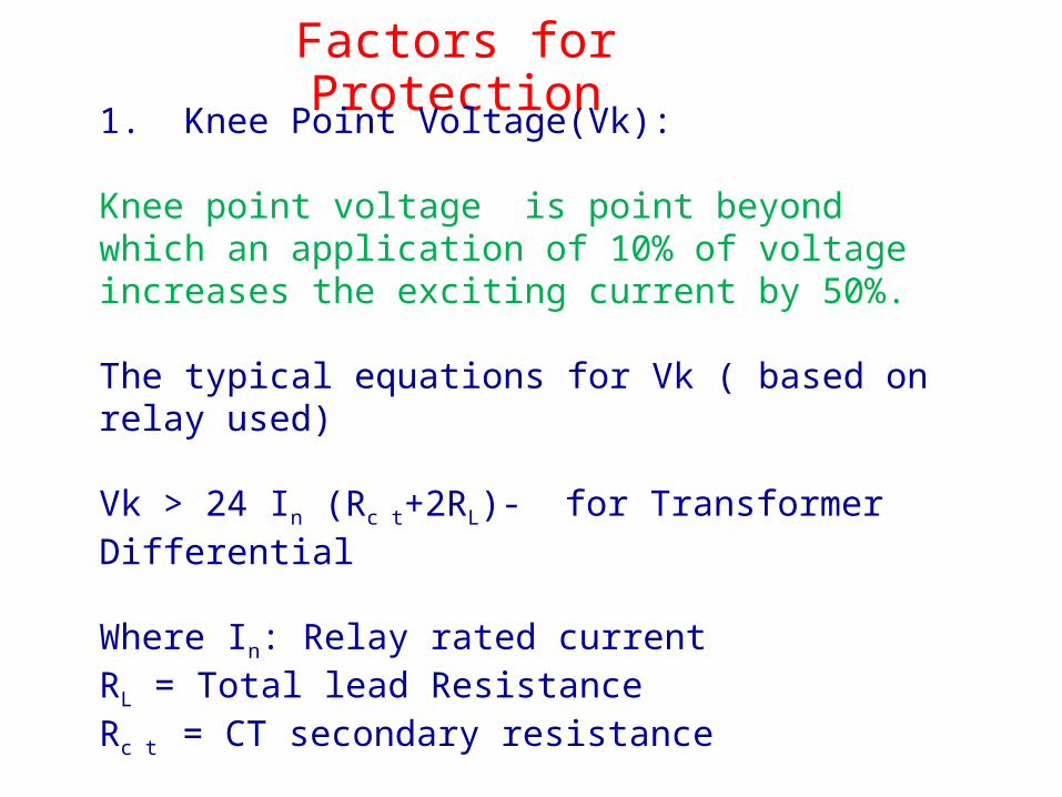
Factors for Protection1. Knee Point Voltage(Vk):
Knee point voltage is point beyond which an application of 10% of voltage increases the exciting current by 50%.
The typical equations for Vk ( based on relay used)
Vk > 24 In (Rc t+2RL)- for Transformer Differential
Where In: Relay rated currentRL = Total lead ResistanceRc t = CT secondary resistance
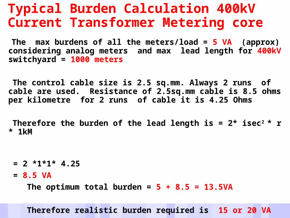
Typical Burden Calculation 400kV Current Transformer Metering core
The max burdens of all the meters/load = 5 VA (approx) considering analog meters and max lead length for 400kV switchyard = 1000 meters
The control cable size is 2.5 sq.mm. Always 2 runs of cable are used. Resistance of 2.5sq.mm cable is 8.5 ohms per kilometre for 2 runs of cable it is 4.25 Ohms
Therefore the burden of the lead length is = 2* isec2 * r * 1kM
= 2 *1*1* 4.25 = 8.5 VA
The optimum total burden = 5 + 8.5 = 13.5VA Therefore realistic burden required is 15 or 20 VA
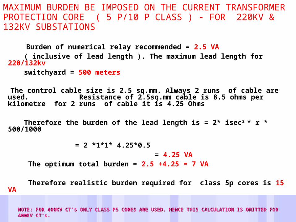
MAXIMUM BURDEN BE IMPOSED ON THE CURRENT TRANSFORMER PROTECTION CORE ( 5 P/10 P CLASS ) - FOR 220KV & 132KV SUBSTATIONS Burden of numerical relay recommended = 2.5 VA ( inclusive of lead length ). The maximum lead length for
220/132kv switchyard = 500 meters
The control cable size is 2.5 sq.mm. Always 2 runs of cable are used. Resistance of 2.5sq.mm cable is 8.5 ohms per kilometre for 2 runs of cable it is 4.25 Ohms
Therefore the burden of the lead length is = 2* isec2 * r * 500/1000 = 2 *1*1*
4.25*0.5 = 4.25 VA
The optimum total burden = 2.5 +4.25 = 7 VA Therefore realistic burden required for class 5p cores is 15 VA
NOTE: FOR 400KV CT's ONLY CLASS PS CORES ARE USED. HENCE THIS CALCULATION IS OMITTED NOTE: FOR 400KV CT's ONLY CLASS PS CORES ARE USED. HENCE THIS CALCULATION IS OMITTED FOR 400KV CT’s. FOR 400KV CT’s.
POTENTIAL TRANSFORMER• PTs are used to reduce the system voltage to level low enough to
suit the rating of protective relays & measuring instruments.
• Types of Construction:• Electromagnetic type
• Conveniently used up to 132 KV.• Capacitor Type
• Economical above 132 KV• Residual Voltage T/F
ELECTROMAGNETIC TYPE VT• Works on the same principle as the Power T/F.• Load to be flow is quite limited depending upon purposes.• As voltage decreases, the accuracy of electromagnetic type PTs
decreases but is acceptable down to 1 % of nominal voltage.• At higher voltages, electromagnetic type PTs becomes very expensive
& hence it is common practice to use a Capacitor Voltage Divider.
Capacitor Type Voltage Transformer• The size of electromagnetic voltage transformers for the higher
voltages is largely proportional to the rated voltage; the cost tends to increase at a disproportionate rate. The capacitor voltage transformer (CVT) is often more economic.
• High voltage capacitors are enclosed in a porcelain housing.• The transient performance of a Capacitor type PT is inferior as compare
to electromagnetic type.
Special Auxilliary Circuit elements are:Compensating Inductance coil: in series with the primary of the intermediate T/F compensates the voltage increase on CV divider.Damping impedance: Avoids ferro-resonance in secondary ckt.Resistor & Spark Gap: Provides necessary protection against
overvoltages.
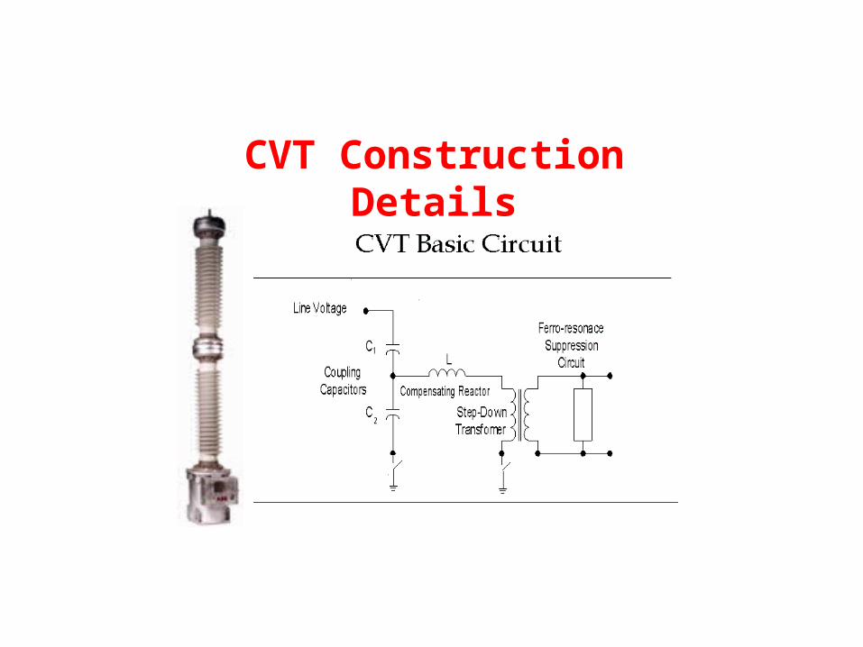
CVT Construction Details
CVT Secondary Voltage
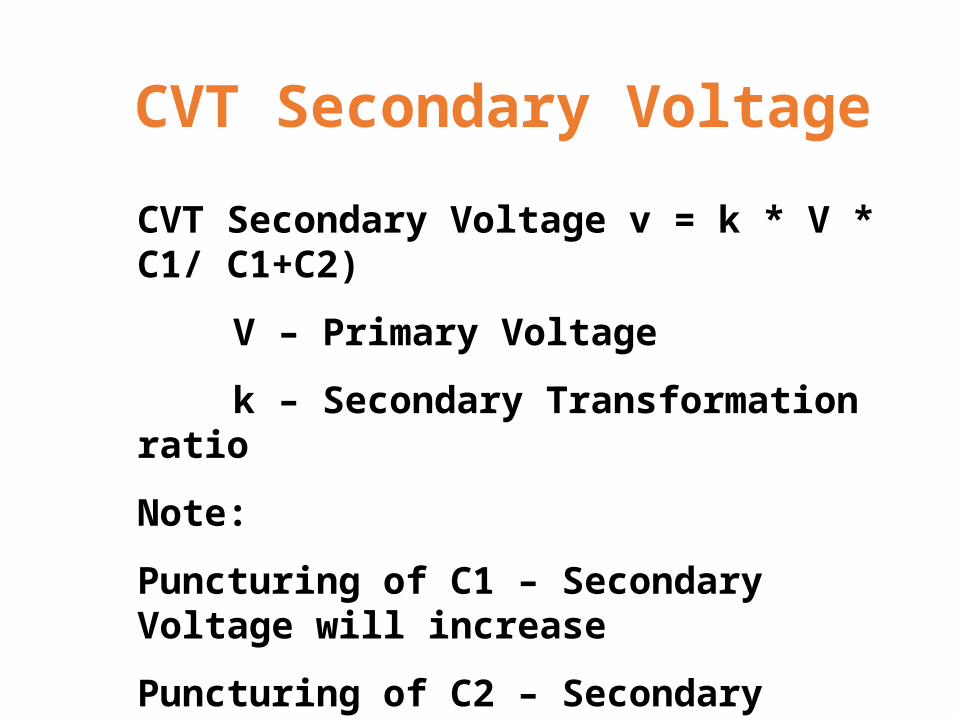
CVT Secondary Voltage v = k * V * C1/ C1+C2)
V – Primary Voltage
k – Secondary Transformation ratio
Note:
Puncturing of C1 – Secondary Voltage will increase
Puncturing of C2 – Secondary Voltage will decrease
Secondary Voltage measurement
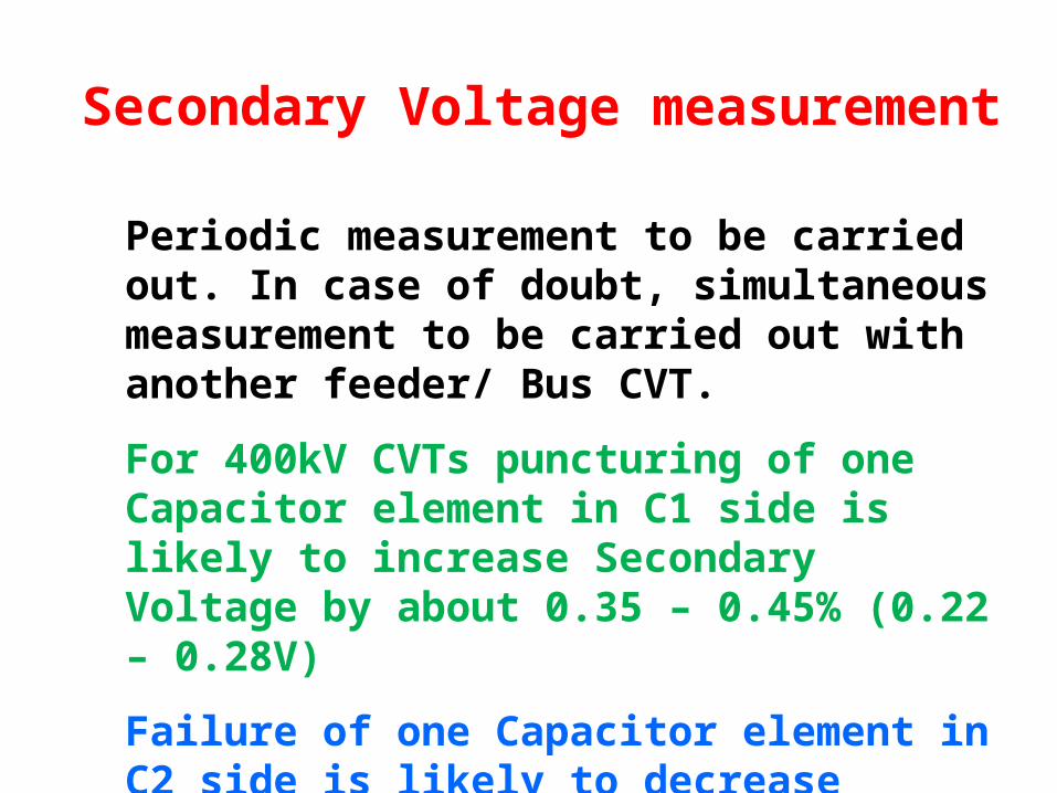
Periodic measurement to be carried out. In case of doubt, simultaneous measurement to be carried out with another feeder/ Bus CVT.
For 400kV CVTs puncturing of one Capacitor element in C1 side is likely to increase Secondary Voltage by about 0.35 – 0.45% (0.22 – 0.28V)
Failure of one Capacitor element in C2 side is likely to decrease Secondary Voltage by 5 – 6% (3.2 – 3.8V)
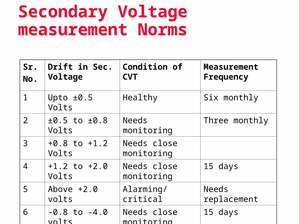
Secondary Voltage measurement Norms
Sr.No.
Drift in Sec. Voltage
Condition of CVT Measurement Frequency
1 Upto ±0.5 Volts Healthy Six monthly
2 ±0.5 to ±0.8 Volts Needs monitoring Three monthly
3 +0.8 to +1.2 Volts Needs close monitoring
4 +1.2 to +2.0 Volts Needs close monitoring
15 days
5 Above +2.0 volts Alarming/ critical Needs replacement
6 -0.8 to -4.0 volts Needs close monitoring
15 days
7 Less than -4.0 volts Alarming Needs replacement
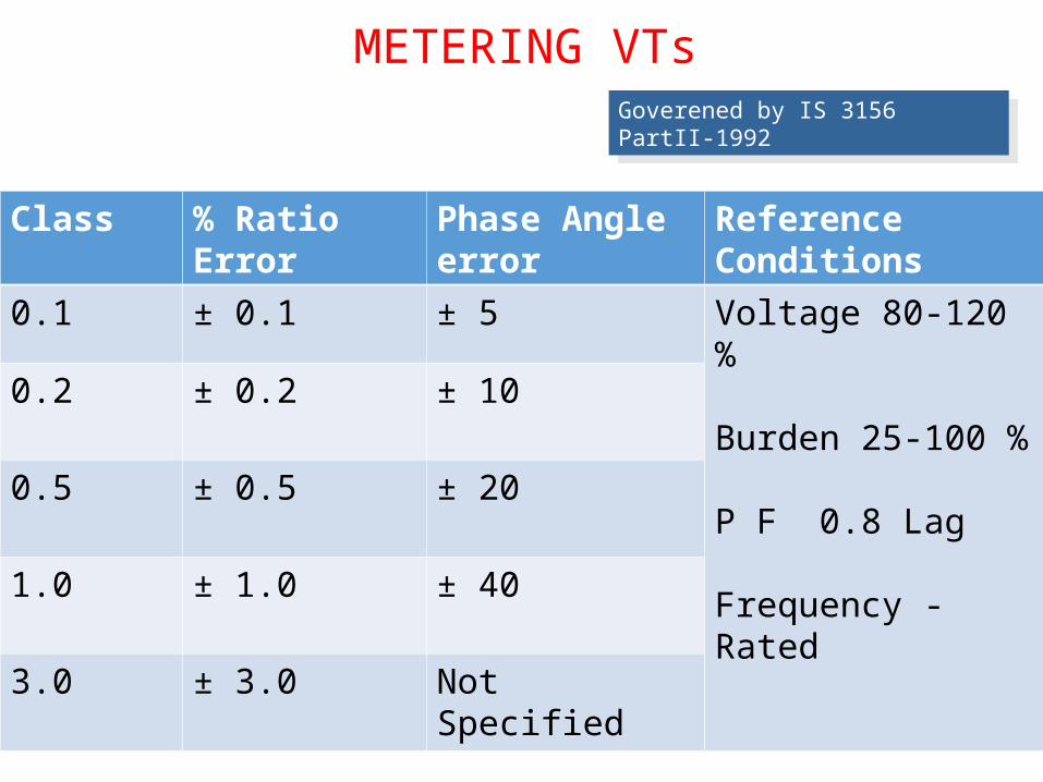
METERING VTsGoverened by IS 3156 PartII-1992
Class % Ratio Error Phase Angle error Reference Conditions
0.1 ± 0.1 ± 5 Voltage 80-120 %
Burden 25-100 %
P F 0.8 Lag
Frequency - Rated
0.2 ± 0.2 ± 10
0.5 ± 0.5 ± 20
1.0 ± 1.0 ± 40
3.0 ± 3.0 Not Specified
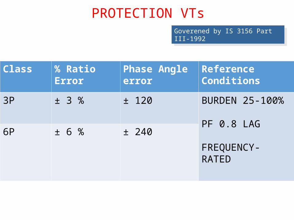
PROTECTION VTsGoverened by IS 3156 Part III-1992
Class % Ratio Error Phase Angle error Reference Conditions
3P ± 3 % ± 120 BURDEN 25-100%
PF 0.8 LAG
FREQUENCY- RATED
6P ± 6 % ± 240
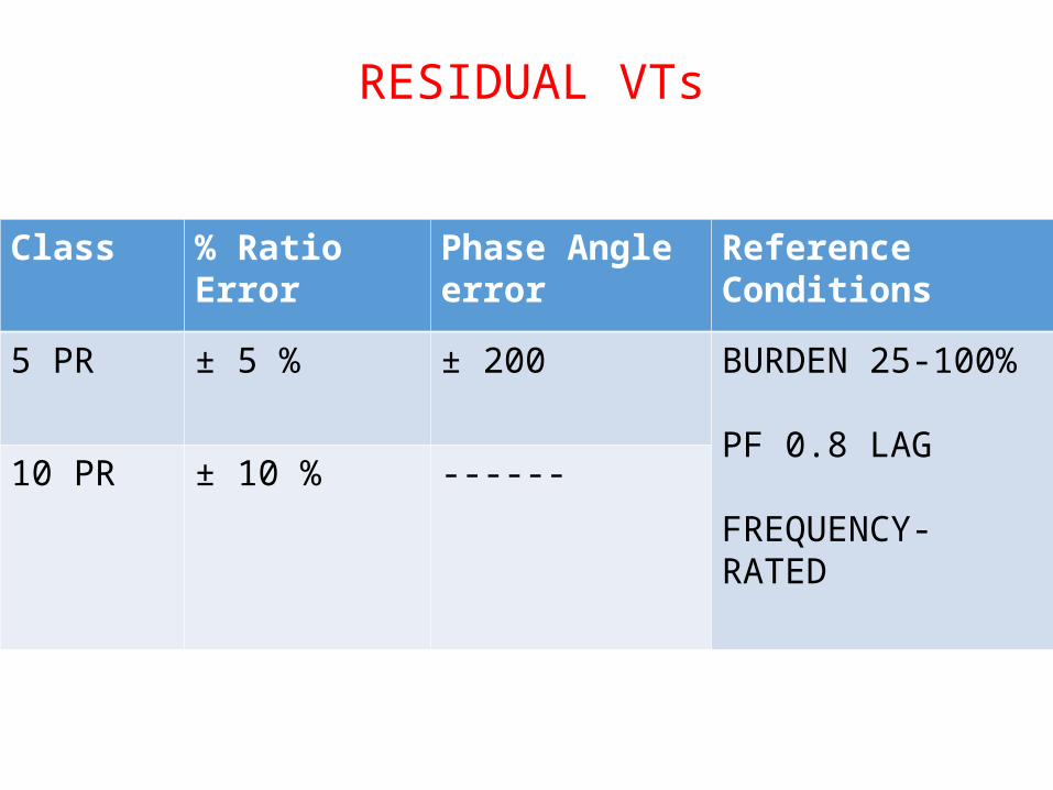
RESIDUAL VTs
Class % Ratio Error Phase Angle error Reference Conditions
5 PR ± 5 % ± 200 BURDEN 25-100%
PF 0.8 LAG
FREQUENCY- RATED
10 PR ± 10 % ------
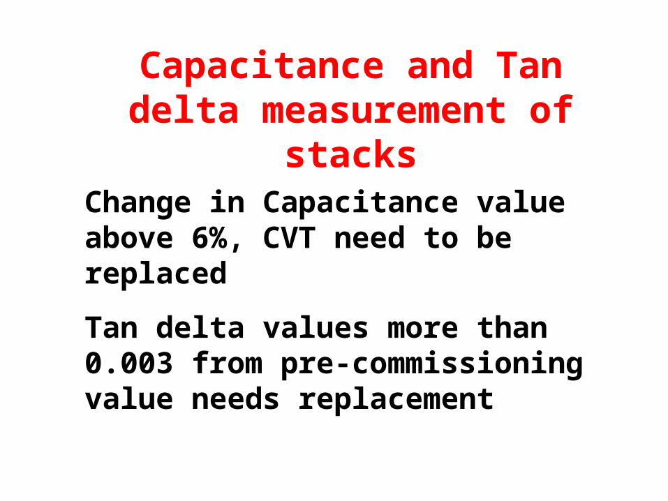
Capacitance and Tan delta measurement of stacks
Change in Capacitance value above 6%, CVT need to be replaced
Tan delta values more than 0.003 from pre-commissioning value needs replacement
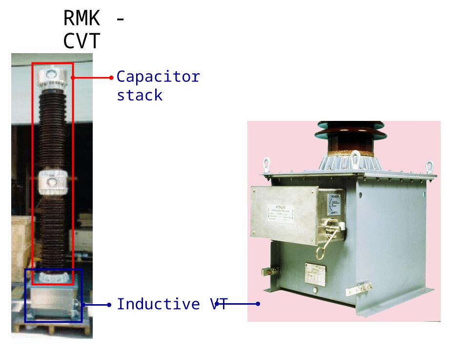
RMK - CVT
Capacitor stack
Inductive VT
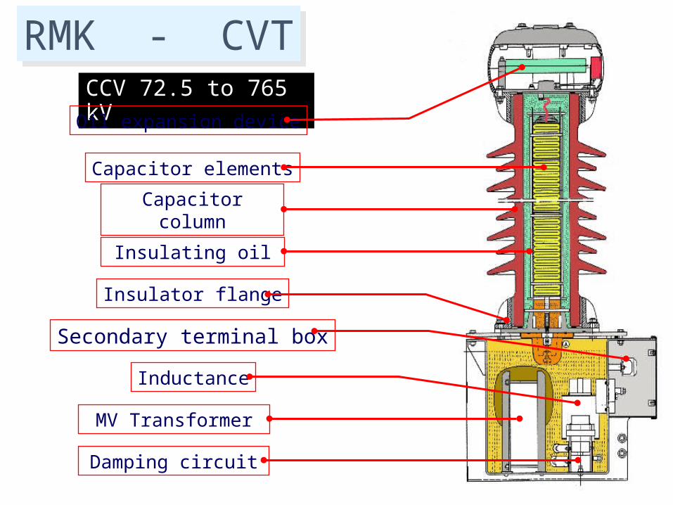
CCV 72.5 to 765 kV
Capacitor elements
Capacitor column
Insulating oil
Insulator flange
Secondary terminal boxInductance
MV Transformer
Oil expansion device
Damping circuit
RMK - CVT
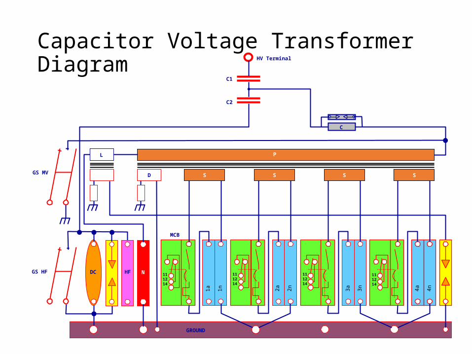
P
Capacitor Voltage TransformerDiagram
P
GROUND
GS HF
HV Terminal
C1
C2
N
4a 4n
111214
1a 1n
111214
2a 2n
111214
3a 3n
111214
MCB
S S S SGS MV D
L
HFDC
C
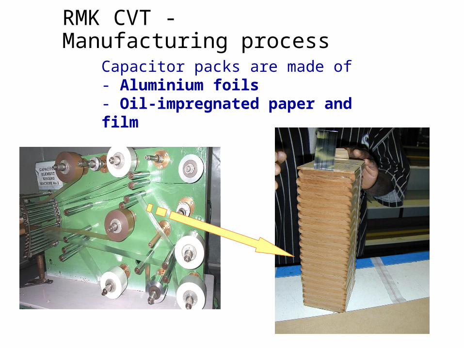
RMK CVT - Manufacturing process
Capacitor packs are made of- Aluminium foils- Oil-impregnated paper and film
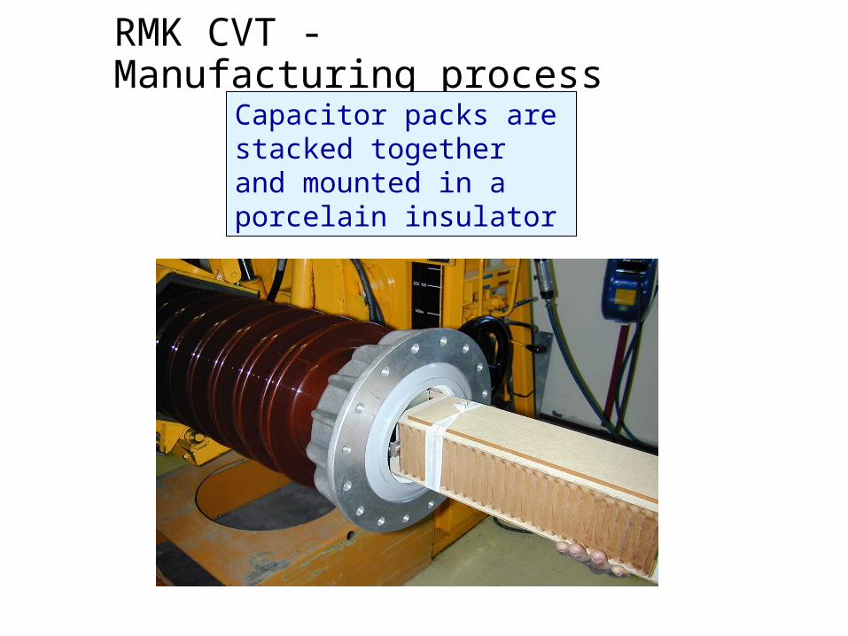
RMK CVT - Manufacturing process
Capacitor packs are stacked together and mounted in a porcelain insulator
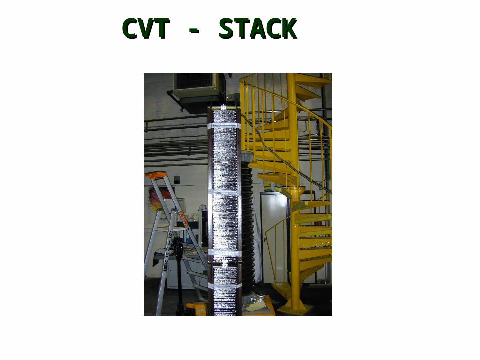
CVT - STACKCVT - STACK
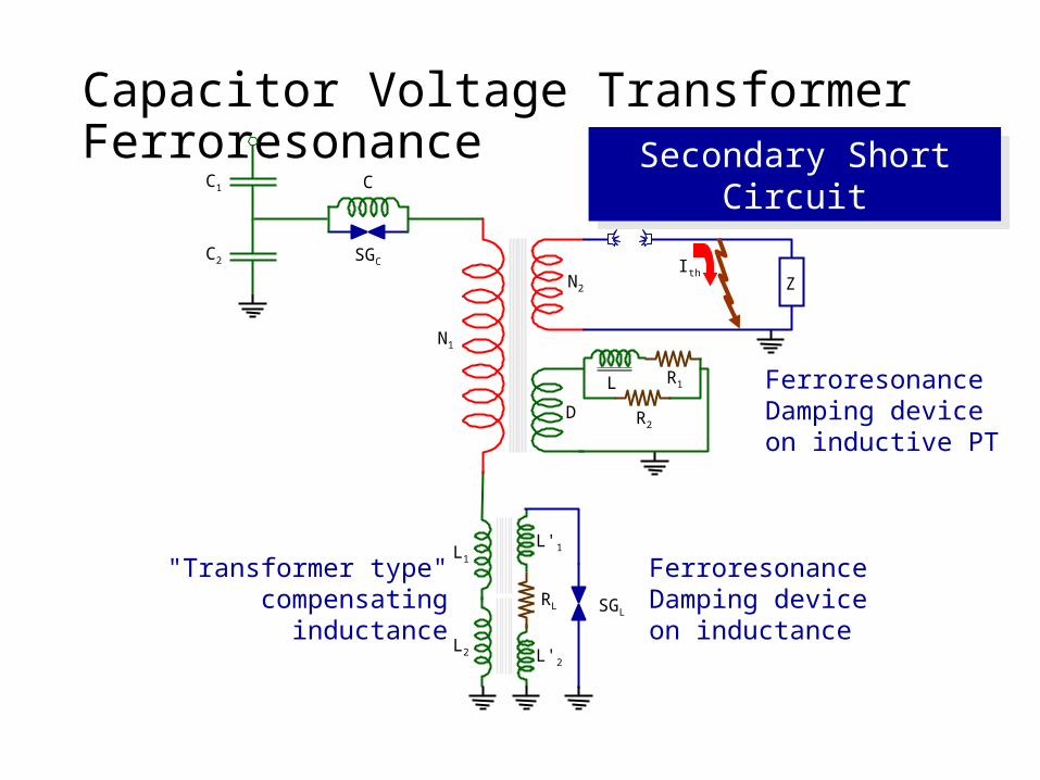
Capacitor Voltage TransformerFerroresonance
L1
L2
ZN2
N1
IthC2
C1
SGC
CSecondary Short
Circuit
LR2
R1
DFerroresonanceDamping deviceon inductive PT
L'1
L'2
RL SGL
FerroresonanceDamping deviceon inductance
"Transformer type"compensating
inductance
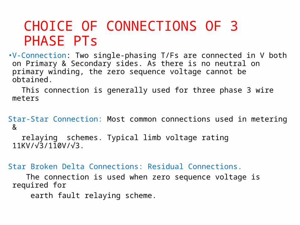
CHOICE OF CONNECTIONS OF 3 PHASE PTs
• V-Connection: Two single-phasing T/Fs are connected in V both on Primary & Secondary sides. As there is no neutral on primary winding, the zero sequence voltage cannot be obtained.
This connection is generally used for three phase 3 wire meters
Star-Star Connection: Most common connections used in metering & relaying schemes. Typical limb voltage rating 11KV/√3/110V/√3.
Star Broken Delta Connections: Residual Connections. The connection is used when zero sequence voltage is required for earth fault relaying scheme.
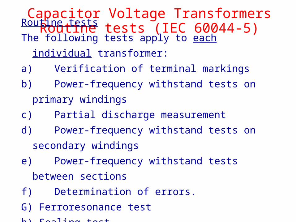
Capacitor Voltage TransformersRoutine tests (IEC 60044-5)Routine tests
The following tests apply to each individual transformer:
a)Verification of terminal markingsb)Power-frequency withstand tests on primary
windings c) Partial discharge measurementd)Power-frequency withstand tests on secondary
windings e)Power-frequency withstand tests between
sections f) Determination of errors.G) Ferroresonance testh) Sealing test
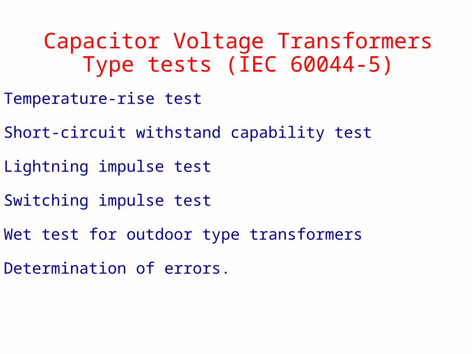
Capacitor Voltage TransformersType tests (IEC 60044-5)
a) Temperature-rise test
b) Short-circuit withstand capability test
c) Lightning impulse test
d) Switching impulse test
e) Wet test for outdoor type transformers
f) Determination of errors.
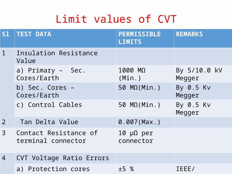
Limit values of CVTSl TEST DATA PERMISSIBLE
LIMITSREMARKS
1 Insulation Resistance Value
a) Primary – Sec. Cores/Earth 1000 MΩ (Min.) By 5/10.0 kV Megger
b) Sec. Cores – Cores/Earth 50 MΩ(Min.) By 0.5 Kv Megger
c) Control Cables 50 MΩ(Min.) By 0.5 Kv Megger
2 Tan Delta Value 0.007(Max.)
3 Contact Resistance of terminal connector
10 μΩ per connector
4 CVT Voltage Ratio Errors
a) Protection cores ±5 % IEEE/C93.1.1990
b) Metering cores ±0.5 % IEC 186
5 Drift in secondary voltage ± 2.0 volts replacement
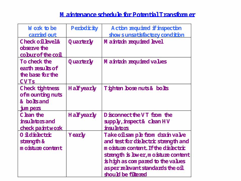
Maintenance schedule for Potential Transformer
Work to be carried out
Periodicity Action required if inspection shows unsatisfactory condition
Check oil level & observe the colour of the coil
Quarterly Maintain required level
To check the earth results of the base for the CVTs
Quarterly Maintain required values
Check tightness of mounting nuts & bolts and jumpers
Half yearly Tighten loose nuts & bolts
Clean the insulators and check paint work
Half yearly Disconnect the VT from the supply, inspect & clean HV insulators
Oil dielectric strength & moisture content
Yearly Take oil sample from drain valve and test for dielectric strength and moisture content. If the dielectric strength is lower, moisture content is high as compared to the values as per relevant standards the oil should be filtered
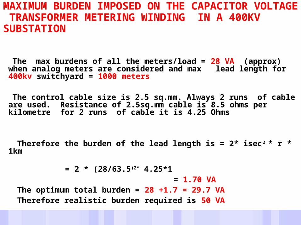
MAXIMUM BURDEN IMPOSED ON THE CAPACITOR VOLTAGE TRANSFORMER METERING WINDING IN A 400KV SUBSTATION
The max burdens of all the meters/load = 28 VA (approx) when analog meters are considered and max lead length for 400kv switchyard = 1000 meters
The control cable size is 2.5 sq.mm. Always 2 runs of cable are used. Resistance of 2.5sq.mm cable is 8.5 ohms per kilometre for 2 runs of cable it is 4.25 Ohms
Therefore the burden of the lead length is = 2* isec2 * r * 1km = 2 * (28/63.5)2* 4.25*1 = 1.70 VA
The optimum total burden = 28 +1.7 = 29.7 VA Therefore realistic burden required is 50 VA