Embed Size (px)
Citation preview

MIDWEST RELIABILITY ORGANIZATION
380 St. Peter Street, Ste.800 St. Paul, MN 55102
P: 651.855.1760 F: 651.855.1712 www.midwestreliability.org
Protection System Misoperations
Prepared by: MRO Protective Relay Subcommittee
April 18, 2016

PROTECTION SYSTEM MISOPERATION │ MRO PROTECTIVE RELAY SUBCOMMITTEE 1
Acknowledgement This publication was developed by a team of Subject Matter Exerts (SME) from MRO member organizations within the MRO footprint. The development of SME teams is an ongoing effort to produce unified application guides for MRO and its Registered Entities. MRO staff wishes to acknowledge and thank those who dedicated their efforts and contributed significantly to this publication. MRO and the MRO Protective Relay Subcommittee, and their organizational affiliations include:
Midwest Reliability Organization
Dan Schoenecker, Vice President Operations
John Seidel, Sr. Manager Operations and Reliability, Event Analysis
Richard Quest, Principal Systems Protection Engineer Operations
MRO Protective Relay Subcommittee Brian Fettig Montana-Dakota Utilities
Casey Malskeit Omaha Public Power District
Ding Lin Manitoba Hydro
Grant Gunderson Minnkota Power Cooperative
Greg Hill Nebraska Public Power District
John Grimm Xcel Energy
Keith Orsted American Transmission Company
Kris Ruud Midcontinent ISO
Michael Gates ITC Midwest
Michael Weir Dairyland Power Cooperative
Robert Soper Western Area Power Administration
Sotero Abraham Saskatchewan Power
Steve Mittelsteadt Basin Electric Power Cooperative
NERC System Protection and Control Subcommittee Representative
Mark Gutzmann Xcel Energy

PROTECTION SYSTEM MISOPERATION │ MRO PROTECTIVE RELAY SUBCOMMITTEE 2
Contents
Preface ............................................................................................................................................. 4
Introduction ..................................................................................................................................... 5
Background ..............................................................................................................................5
Target Audience .......................................................................................................................5
Chapter One: Overcurrent Relay Setting ........................................................................................ 6
Overcurrent Relaying ...............................................................................................................6
Overcurrent Relay Setting Related Misoperations ...................................................................7
Application of Direct Trip Overcurrent Relay/Elements in Transmission Line Protection ......................................................................................... 7
Application of Direct Trip Overcurrent Relay/Elements in Transformer Protection ................................................................................................... 9
Misoperations Related to Overcurrent Protection Used in Pilot Transmission Line Protection Schemes ................................................................................................................11
Application of Overcurrent Protection in Pilot Transmission Line Protection Schemes ............................................................................ 11
Comparison of High Set Instantaneous Ground Overcurrent Relays with Zone 1 Ground Distance Relays ......................................................................................................................13
Chapter Two: Directional Comparison Blocking (DCB) Schemes .............................................. 14
Advantages and Liabilities of DCB Schemes ........................................................................14
The Westinghouse KDAR Directional Comparison Blocking Scheme .................................15
Commissioning DCB Schemes ..............................................................................................17
Coordination of Fault Detecting and Blocking Elements ......................................................18
Distance Element versus Directional Ground Overcurrent Elements ....................................18
Communication Timer Settings ..............................................................................................18
Communication Equipment Life Cycle ..................................................................................19
Carrier Checkback and Alarms ..............................................................................................19
Frequency Selection ...............................................................................................................19
General Dependency on Communication for Security ...........................................................20
Condition Assessment Tests ...................................................................................................20
Chapter Three: Direct Transfer Trip (DTT) Schemes .................................................................. 21
Direct Transfer Trip Schemes ................................................................................................21
Functional DTT description and background information .....................................................21

PROTECTION SYSTEM MISOPERATION │ MRO PROTECTIVE RELAY SUBCOMMITTEE 3
Security Considerations ..........................................................................................................22
Methods to Reduce Undesirable Trips Due to Communication Channel Noise ....................23
DTT Receive Validation Time Delays ...................................................................................23
Channel Bandwidth Considerations .......................................................................................23
Dual communication channel DTT receive voting schemes ..................................................24
PLC Application of Skewed Hybrids .....................................................................................26
Fiber Optic Digital Communications .....................................................................................26
Conclusion .................................................................................................................................... 27
Additional Reference Materials .................................................................................................... 28

PROTECTION SYSTEM MISOPERATION │ MRO PROTECTIVE RELAY SUBCOMMITTEE 4
Preface Midwest Reliability Organization (MRO) is dedicated to its vision to maintain and improve the quality of life through a highly reliable regional bulk power system. MRO operates as a cross-border Regional Entity and is headquartered in Saint Paul, Minnesota. The MRO Region covers roughly one million square miles spanning the provinces of Saskatchewan and Manitoba, and all or parts of the states of Illinois, Iowa, Minnesota, Michigan, Montana, Nebraska, North Dakota, South Dakota and Wisconsin. The region includes more than 130 organizations that are involved in the production and delivery of electricity to more than 20 million people. These organizations include municipal utilities, cooperatives, investor-owned utilities, transmission system operators, a federal power marketing agency, Canadian Crown Corporations, and independent power producers. MRO's primary responsibilities are to: ensure compliance with mandatory reliability standards by entities who own, operate, or use the interconnected, international bulk power system; conduct assessments of the grid's ability to meet electricity demand in the region; and analyze regional system events.

PROTECTION SYSTEM MISOPERATION │ MRO PROTECTIVE RELAY SUBCOMMITTEE 5
Introduction Background
Since 2012, NERC event analysis metrics have identified Protection System Misoperations as the leading initiating cause of Bulk Electric System (BES) events. In addition, Protection System Misoperations have a positive correlation with increased transmission outage severity. In 2015, using the results from the Protection Systems Misoperations Task Force effort to identify causes of mis-operations and the 2015 State of Reliability Report, NERC announced a goal of reducing misoperations due to the most common causes. To accomplish this goal, and to provide techniques particularly effective within MRO, the MRO Protective Relay Subcommittee (PRS) embarked on a project to identify causes of, and opportunities to prevent misoperations observed within the MRO Region. The PRS has prepared this paper discussing the misoperation modes of Protection System schemes observed to have a disproportionate share of misoperations within the MRO Region. This paper also identifies approaches to reduce their occurrence. Three schemes are discussed in this paper, with others to follow in subsequent papers. The three schemes are, Overcurrent Relaying, Directional Comparison Blocking (DCB) Schemes, and Direct Transfer Tripping (DTT) Schemes. This document will be made available to all who report misoperations in the MRO Region, and will be publicly available on the MRO website. The PRS project is part of a larger effort by the MRO Operating Committee to improve reliability through improved Human Performance. Human Performance plays a crucial role both in preventing misoperations before they occur, and in improving Protection System operation after a misoperation has been observed through effective mitigation. One of the leading causes of misoperations is incorrect settings or logic. Clearly improved Human Performance can reduce the rate of misoperations due to incorrect setting or logic. When misoperations are observed, improvements in investigations will result in better identification of why the particular system misoperated. This will also serve to reduce the likelihood of misoperations in similar schemes sharing the same susceptibility to misoperate. Target Audience
This technical paper is intended for all personnel associated with the design, installation, testing and maintenance of BES protection system equipment.
PROTECTION SYSTEM MISOPERATION │ MRO PROTECTIVE RELAY SUBCOMMITTEE 6
Chapter One: Overcurrent Relay Setting
Overcurrent Relaying
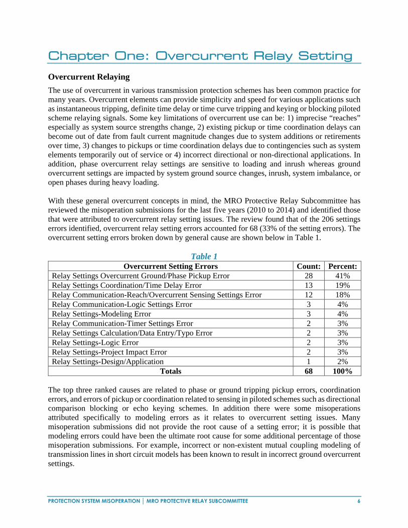
The use of overcurrent in various transmission protection schemes has been common practice for many years. Overcurrent elements can provide simplicity and speed for various applications such as instantaneous tripping, definite time delay or time curve tripping and keying or blocking piloted scheme relaying signals. Some key limitations of overcurrent use can be: 1) imprecise “reaches” especially as system source strengths change, 2) existing pickup or time coordination delays can become out of date from fault current magnitude changes due to system additions or retirements over time, 3) changes to pickups or time coordination delays due to contingencies such as system elements temporarily out of service or 4) incorrect directional or non-directional applications. In addition, phase overcurrent relay settings are sensitive to loading and inrush whereas ground overcurrent settings are impacted by system ground source changes, inrush, system imbalance, or open phases during heavy loading. With these general overcurrent concepts in mind, the MRO Protective Relay Subcommittee has reviewed the misoperation submissions for the last five years (2010 to 2014) and identified those that were attributed to overcurrent relay setting issues. The review found that of the 206 settings errors identified, overcurrent relay setting errors accounted for 68 (33% of the setting errors). The overcurrent setting errors broken down by general cause are shown below in Table 1.
Table 1 Overcurrent Setting Errors Count: Percent:
Relay Settings Overcurrent Ground/Phase Pickup Error 28 41% Relay Settings Coordination/Time Delay Error 13 19% Relay Communication-Reach/Overcurrent Sensing Settings Error 12 18% Relay Communication-Logic Settings Error 3 4% Relay Settings-Modeling Error 3 4% Relay Communication-Timer Settings Error 2 3% Relay Settings Calculation/Data Entry/Typo Error 2 3% Relay Settings-Logic Error 2 3% Relay Settings-Project Impact Error 2 3% Relay Settings-Design/Application 1 2%
Totals 68 100% The top three ranked causes are related to phase or ground tripping pickup errors, coordination errors, and errors of pickup or coordination related to sensing in piloted schemes such as directional comparison blocking or echo keying schemes. In addition there were some misoperations attributed specifically to modeling errors as it relates to overcurrent setting issues. Many misoperation submissions did not provide the root cause of a setting error; it is possible that modeling errors could have been the ultimate root cause for some additional percentage of those misoperation submissions. For example, incorrect or non-existent mutual coupling modeling of transmission lines in short circuit models has been known to result in incorrect ground overcurrent settings.

PROTECTION SYSTEM MISOPERATION │ MRO PROTECTIVE RELAY SUBCOMMITTEE 7
The overcurrent setting errors were also broken down by looking at the specifics of the overcurrent type/scheme application based on the data that was available from the submissions. The top 6 identified causes are shown below in Table 2.
Table 2 Overcurrent Type/Scheme Application Count: Percent:
Ground Instantaneous Overcurrent Issue 21 36% Ground Time Overcurrent Issue 15 25% Echo Key Issue 9 16% DCB Scheme/Issue 5 9% Phase Overcurrent Issue 5 9% Directional Issue 3 5%
Totals 58 100% This identification method indicates misoperations are caused by overcurrent related setting errors primarily due to overly sensitive ground instantaneous tripping pickup, lack of ground time overcurrent coordination, pickup errors in overcurrent used by DCB and echo keying piloted schemes, and to a lesser extent phase overcurrent and incorrect or lack of directional settings. In order to minimize misoperations due to overcurrent related settings errors, the PRS overcurrent review team elected to document some considerations and observations related to setting the overcurrent relay (or overcurrent elements in microprocessor relays) in various specific overcurrent applications which include:
Direct tripping ground and phase overcurrent relays on transmission lines utilizing instantaneous and time applications with discussion of directional versus non-directional settings.
Direct tripping ground and phase overcurrent relays on transformers utilizing instantaneous and time applications with discussion of directional versus non-directional settings.
Communication applications utilizing instantaneous ground and phase overcurrent relays and directional versus non-directional applications on transmission piloted schemes such as DCB and echo key applications.
Overcurrent Relay Setting Related Misoperations
Based on the misoperation data collected within the MRO Region from 2010 to 2014, approximately 60% of the overcurrent setting related protection misoperations were attributed to the overcurrent relays/elements that are used for direct tripping. This section of the paper summarizes the general issues concerning setting the overcurrent relays that are used for direct tripping and identifies a few factors to consider when developing settings.
Application of Direct Trip Overcurrent Relay/Elements in Transmission Line Protection The sections below list some major factors to consider when setting the direct trip overcurrent relays (or elements in microprocessor relays) in transmission line protection.

PROTECTION SYSTEM MISOPERATION │ MRO PROTECTIVE RELAY SUBCOMMITTEE 8
1. Setting Considerations for Phase Instantaneous Overcurrent Relays: The pickup setting of the phase instantaneous overcurrent relay has to be set above the
maximum possible load (meets Relay Loadability criteria) on the line including under maximum recoverable swing conditions.
This relay has to be set to not detect any external faults (faults outside of the protected
element zone) under all system operating conditions (such as maximum or minimum generation, and cases where some power system elements are out of service, etc.).
This relay can be non-directional or directional. If the relay is non-directional, external
faults on both forward and reverse directions would need to be taken into account when setting this relay to ensure that it only operates for the protected line.
For relays that are not immune to DC offset such as the electromechanical relays and
the solid state type of relays, DC offset should be taken into account when calculating the fault current and determining the settings.
A reasonable margin should be included when setting this relay to cover for the CT
error, modeling error and relay measurement error, etc.
2. Setting Considerations for Phase Time Overcurrent Relays: The pickup setting of the phase time overcurrent relay has to be set above the maximum
possible load (meets Relay Loadability criteria) on the line including under maximum recoverable swing conditions.
The time delay settings (or the time curve selection) of the phase time overcurrent relay
has to be set so it will coordinate with the protection elements of the adjacent power system elements. The proper coordination has to be maintained under all system operating conditions (such as maximum or minimum generation, cases where some power system elements are out of service, etc.).
This relay can be non-directional or directional. If the relay is non-directional,
coordination with protection elements of the adjacent power system elements in both directions would need to be taken into account.
The phase time overcurrent relay is rarely used on the transmission line protection (at
transmission voltage level) in actual industry practice, due to the restrictions above.
3. Setting Considerations for Ground Instantaneous Overcurrent Relays: This relay has to be set to not detect any external faults (faults outside of the protected
element) under all system operating conditions (such as maximum or minimum generation, cases where some power system elements are out of service, etc.).
A reasonable margin should be included for this consideration to cover for the CT error,
modeling error and relay measurement error, etc.

PROTECTION SYSTEM MISOPERATION │ MRO PROTECTIVE RELAY SUBCOMMITTEE 9
This relay can be non-directional or directional. If the relay is non-directional, external faults on both forward and reverse directions would need to be taken into account.
Transmission line mutual coupling effect plays an important role in the operation of
the ground overcurrent relays. Therefore, it is critical to include the mutual coupling effect in the fault simulation model in determining the zero sequence current when setting the ground instantaneous overcurrent relays and when selecting appropriate polarization methods.
According to the MRO protection misoperation statistics, the highest number of
overcurrent setting related misoperations is a result of incorrect setting of the ground instantaneous overcurrent relays. Based on this, extra care should be taken when setting this relay.
4. Setting Considerations for Ground Time Overcurrent Relays:
The ground time overcurrent relay is commonly used on the transmission line protection as primary and backup protection. This element is particularly useful in detecting high impedance faults.
The pickup setting of the ground time overcurrent relay has to be set above the
maximum possible unbalance of the transmission line, and must pick up for all internal faults under all reasonable system configurations.
The time delay settings (or the time curve selection) of the ground time overcurrent
relay has to be set so it will coordinate with the protection elements of the adjacent power system elements. The proper coordination has to be maintained under all system operating conditions (such as maximum or minimum generation, and cases where some power system elements are out of service, etc.).
Transmission line mutual coupling effect plays an important role in the operation of
the ground overcurrent relays. Therefore, it is critical to include the mutual coupling effect in the fault simulation model when doing the coordination analysis and determining the settings and polarization of the ground time overcurrent relays.
This relay can be non-directional or directional. If the relay is non-directional,
coordination with protection elements of the adjacent power system elements in both directions would need to be taken into account.
Application of Direct Trip Overcurrent Relay/Elements in Transformer Protection Overcurrent relays are used in transformer protection to provide overload protection for the transformer and backup protection for external faults. The sections below lists some major factors to consider when setting the overcurrent relays if they are used in transformer protection.
1. Setting Considerations for Phase Instantaneous Overcurrent Relays:
Phase instantaneous relay settings are sometimes used on the high voltage side of the transformer to provide backup high speed protection for a fault on the high voltage side

PROTECTION SYSTEM MISOPERATION │ MRO PROTECTIVE RELAY SUBCOMMITTEE 10
of the transformer in case there is a CT saturation issue and the transformer differential relay fails to detect this fault.
Transformer inrush current will need to be taken into account when setting this relay. The pickup setting of the phase instantaneous overcurrent relay has to be set above the
maximum possible load (meets Relay Loadability criteria) on the transformer including under maximum recoverable swing conditions.
This relay has to be set to not detect any external faults (faults on the low voltage side
of the transformer) under all system operating conditions (such as maximum or minimum generation, cases where some power system elements are out of service, etc.)
A reasonable margin should be included for this consideration to cover for the CT error,
modeling error and relay measurement, etc.
2. Setting Considerations for Phase Time Overcurrent Relays: The pickup setting of the phase time overcurrent relay has to be set above the maximum
possible load (meets Relay Loadability criteria) on the transformer including under maximum recoverable swing conditions.
The time delay settings (or the time curve selection) of the phase time overcurrent relay
has to be set so it will coordinate with the protection relaying of the adjacent power system elements. This can be difficult as many of the adjacent elements will be lines using distance elements with definite time delays. Proper coordination has to be maintained under all system operating conditions (such as maximum or minimum generation, cases where some power system elements are out of service, etc.).
The pickup and the time delay settings (or the time curve selection) of the phase time
overcurrent relay has to be set so it will coordinate with the through-fault damage curve of the transformer.
3. Setting Considerations for Ground Time Overcurrent Relays:
Ground time overcurrent relay can be used on the high voltage side neutral, low voltage side neutral or inside the tertiary of the transformer.
The pickup setting of the ground time overcurrent relay has to be set above the
maximum possible unbalance current that will go through the connected relays. The time delay settings (or the time curve selection) of the ground time overcurrent
relay has to be set so it will coordinate with the protection relaying of the adjacent power system elements. The proper coordination has to be maintained under all system operating conditions (such as maximum or minimum generation, cases where some power system elements are out of service, etc.).

PROTECTION SYSTEM MISOPERATION │ MRO PROTECTIVE RELAY SUBCOMMITTEE 11
Misoperations Related to Overcurrent Protection Used in Pilot Transmission Line Protection Schemes
Based on misoperation data collected within the MRO Region from 2010 to 2014, Directional Comparison Blocking schemes and Echo Keying schemes account for the majority of overcurrent setting related pilot protection scheme misoperations. This section of the paper focuses on factors to consider when setting overcurrent protection used in pilot transmission line protection schemes, with emphasis on DCB and Echo Keying.
Application of Overcurrent Protection in Pilot Transmission Line Protection Schemes Pilot line protection schemes frequently use distance protection for detection of interphase faults and ground overcurrent protection for detection of ground faults. Fault resistance is usually small in the case of interphase faults, but can be high in the case of ground faults. Typically distance protection cannot be set sensitive enough to detect higher resistance faults. For this reason, ground overcurrent protection is commonly used. However, high resistance faults do not typically cause system stability issues or power quality issues. Setting sensitive ground overcurrent protection to detect high resistance faults in a solidly grounded system often times provides minimal benefit to system reliability, while resulting in a higher risk of pilot protection scheme misoperation. The sections below list factors to consider when setting instantaneous overcurrent protection (directional or non-directional) in pilot protection schemes.
1. Setting Considerations for Instantaneous Overcurrent Protection used in Pilot
Transmission Line Protection Schemes The overcurrent relaying used for blocking at the local terminal of a transmission line
should be set more sensitive than the overcurrent relaying used for tripping at the remote terminal of a transmission line. A common margin used for the overcurrent relay pickup is 2:1 for remote terminal tripping with respect to local terminal blocking. For negative sequence and residual overcurrent relays, a ratio as high at 3:1 is sometimes used for remote terminal tripping with respect to local terminal blocking. Safety margins should take into account CT error, relay error, and system modeling errors.
Overcurrent relay pickup settings should be calculated based on an accurate fault study which takes the proper system contingencies into account. Correct modeling of transmission line data, transmission line mutual coupling, and accurate equivalent models for neighboring systems are important factors in the accuracy of the fault study.
Different overcurrent relay sensitivities on each end of a transmission line can cause
mis-coordination for external faults. This situation can occur when using dissimilar relay types at each line terminal or when using different current transformer ratios at each line terminal. In DCB schemes, the operating times of the overcurrent relays used for blocking and tripping must be properly studied to ensure coordination. The overcurrent relay operating times are highly dependent on the sensitivity. To ensure coordination, the best practice is to use matching relays and assure that the blocking element is set more sensitively than the remote tripping element.

PROTECTION SYSTEM MISOPERATION │ MRO PROTECTIVE RELAY SUBCOMMITTEE 12
Transient DC offset has the potential to cause overreach of instantaneous overcurrent
protection. Modern microprocessor relays are usually designed to effectively filter out the DC component. Suitable overcurrent relay pickup settings, which accommodate DC offset, should be considered for relay technologies that do not effectively reject the DC component.
Careful consideration should be given to the effects of three terminal lines and the
winding configuration of any line tapped transformers when determining overcurrent relay pickup settings. This is especially true in permissive schemes which require simultaneous fault detection at all terminals for high speed tripping. DCB schemes will typically trip the two strongest terminals high speed, followed sequentially by a third terminal too weak to initially detect the fault. That is a strength of the DCB scheme on three terminal lines.
Coordination of overcurrent relaying at one end of a transmission line with distance
relaying at the opposite end of a transmission line should be avoided. Varying system conditions can make the coordination between these different relay types very difficult.
2. Directional Sensing Considerations for Instantaneous Overcurrent Protection used in
Pilot Transmission Line Protection Schemes The directional overcurrent polarization methods used at each end of a transmission
line should match. For example, the use of negative sequence current polarization at one end of a transmission line, and zero sequence current polarization at the opposite end of a transmission line should be avoided.
Directional element sensitivity mismatches at each terminal of a transmission line can
cause misoperation. This situation can occur when using different relays which have dissimilar polarizing and operating quantities or different minimum sensitivity thresholds for directional polarization. To ensure coordination, the best practice is to use matching relays at the local and remote terminals of a line.
Directional ground overcurrent relays using negative sequence quantities for
directional polarization should be considered as an alternative to using zero sequence polarization quantities at autotransformer locations and locations where transmission line mutual coupling is involved. Zero sequence polarized directional units can lose directionality in these applications.
The directional polarization method used at each terminal of a transmission line should
have sufficient operating quantities for the desired protection zone. These operating quantities should be evaluated by a fault study over a suitable range of system contingencies.

PROTECTION SYSTEM MISOPERATION │ MRO PROTECTIVE RELAY SUBCOMMITTEE 13
Comparison of High Set Instantaneous Ground Overcurrent Relays with Zone 1 Ground Distance Relays
High set instantaneous ground overcurrent elements are used to provide high speed clearing of high current ground faults. They must be set to not operate for external faults. This requires that the relays be set above the maximum remote end fault current with the strongest system available behind the relay. Determining this setting is not straight forward. It not only depends on the strength of the system behind the relay for an initial fault, but also on the increased strength of the system when reclosing after a fault on a line immediately beyond the protected line. The system may be relatively stronger during the reclosing of a single end. This may result in over-tripping of lines adjacent to the reclosed end. Many relays are sensitive to DC offset in fault currents, and that must be taken into consideration. Predicting the amount of line coverage is also not straight forward. Setting the relay at 120% of the maximum remote fault current (an extremely aggressive setting) may result in little or no coverage for faults on the line. This will depend both on line characteristics, and the source strength behind the terminal at the time of the fault.
In contrast to the setting difficulties and line coverage of the instantaneous ground overcurrent relay mentioned above, a Zone 1 distance element on 2 terminal lines is relatively immune to changes in source strength. Some older relays may need to be desensitized to phase-phase-ground faults, but all versions give relatively predictable fault coverage of the protected line. In modern microprocessor based relays, ground distance elements are low cost, and provide superior and more consistent fault coverage for large ground faults.

PROTECTION SYSTEM MISOPERATION │ MRO PROTECTIVE RELAY SUBCOMMITTEE 14
Chapter Two: Directional Comparison Blocking Schemes Advantages and Liabilities of DCB Schemes
DCB schemes provide dependable fault clearing regardless of the success or failure of communication. This feature often makes them the logical choice where high speed clearing is required to ensure system stability. They also provide a simpler solution to three terminal line protection, as compared to permissive schemes. In an era where the availability and quality of leased protection communication circuits is vanishing, DCB schemes over power line carrier use a robust communication channel entirely under control of the electric utility. The emphasis on providing high speed clearing even when communications fail, tends to result in unnecessary tripping during those failures. The use of sensitive ground overcurrent detecting relays, as opposed to ground distance elements, may increase this tendency. From 2010 through 2014 forty-five misoperations involving DCB schemes were reported in the MRO region. All involved some type of failure to receive a blocking signal, and all occurred during an external fault. Nearly one out of four of the misoperations had no root cause identified. The following table summarizes the DCB misoperations.
Table 3 Misoperation Count: Percent:
1. Human Performance Issues: Insufficient Coordination Time 5 11% Trip & Block Mis-coordination 4 9% As Left Field Errors 4 9%
2. Substation Yard Equipment:
Tuning/Coupling Equipment 3 7% Coaxial Cable Problems 2 4% Spark Gaps 2 4% Wave Trap Problems 2 4%
3. Control House Equipment: Transmitter/Receiver Failures 4 9%
4. Intermittent Blocking Signal: 8 18%
5. Unknown Problem: 11 25%
Total: 45 100%

PROTECTION SYSTEM MISOPERATION │ MRO PROTECTIVE RELAY SUBCOMMITTEE 15
The Westinghouse KDAR Directional Comparison Blocking Scheme
This early electromechanical realization of a DCB scheme remains in widespread use within MRO. A discussion of its operation, and functional requirements illustrate the requirements of all DCB schemes. It also shows opportunities for reducing misoperations using the capabilities of modern digital relays and power line carrier equipment. All DCB schemes use overreaching fault detectors which trip after a short delay to allow the receipt of a blocking signal, blocking elements to detect external faults which may be seen by the overreaching tripping elements, communication equipment (predominantly power line carrier) to transmit local blocking signals to the remote terminal, and a means to delay tripping just long enough for a blocking signal to be received. For the DCB scheme to operate properly, all of the following requirements must be met:
The forward fault detectors at each end must operate for any internal fault (short circuit)
under reasonable source configurations. The local blocking elements must operate for any reverse external fault which may also
operate the remote fault detectors. The local blocking elements must operate fast enough to deliver a blocking signal to the
remote end before the trip delay time expires.
Figure 1: DCB Logic Using Distance Elements Only
In the KDAR scheme, the trip time delay is fixed, determined by the operating time of auxiliary relays in the KA-4 pilot logic relay. The time delay requires a transmitter key to receiver output delay of 3.8 ms (or less), the delay associated with TC type on/off carrier equipment designed for use in the KDAR scheme. It also requires that the blocking elements key the transmitter as fast, or

PROTECTION SYSTEM MISOPERATION │ MRO PROTECTIVE RELAY SUBCOMMITTEE 16
faster than the remote fault detector pick up. The KDAR scheme meets these and all other DCB requirements in slightly different ways for ground and multi-phase faults.
Figure 2: KDAR DCB Logic
Ground Faults: The fault detector in the KDAR scheme is the KRD-4 directional ground overcurrent relay. This relay must be set to pick up for all internal faults under the weakest reasonable configuration of sources. Because of this it will often have very large over reaching ability with normal or strong source configurations. The blocking element in the KDAR scheme is a non-directional ground overcurrent relay (IOC) embedded in the KA-4 logic relay. If the local blocking element is set at half the level of the remote tripping element, then the local blocking element will operate for any external fault that may be seen by the remote tripping element regardless of source configuration. The required operating speed of the blocking element is attained through several features of the scheme. The non-directional blocking relay is inherently faster than the directional tripping relay. When set at half the pickup of the remote tripping relay, the blocking relay will receive twice the operating current relative to pick up. The blocking relay keys by opening closed contacts, while the tripping relay operates by closing normally open contacts. All three of these features make the local blocking element faster than the remote tripping element. Any operation of the local non- directional blocking element for an internal fault is over ridden by the local directional tripping element. A very short transmission of blocking signal is possible, but inconsequential.
Multi-phase Faults: The fault detector in the KDAR scheme is the KD-10 distance relay, and the blocking relay is a reverse reaching KD-11 relay. For a two terminal line, setting the local blocking element the same as the remote tripping relay will ensure that the local blocking element will operate for any external fault that the remote tripping relay may see. The magnitude of the line impedance will provide a security margin. These relays have virtually identical operating times, which will vary somewhat with the location of the fault within their characteristic. Most external faults will operate the local blocking element as fast, or faster, than the remote tripping element as

PROTECTION SYSTEM MISOPERATION │ MRO PROTECTIVE RELAY SUBCOMMITTEE 17
the fault impedance will fall deeper within the blocking characteristic. For very close-in external faults the offset characteristic of the KD-11 will prevent slow operation. Similar to the ground elements, keying is via opening closed contacts, and tripping element operation is via closing normally open contacts. Operation of a local blocking element for an internal fault due to its offset characteristic is over ridden by the local tripping element. When set up properly, the KDAR scheme meets all the performance requirements for a properly operating DCB scheme. It meets these requirements by using carefully matched equipment and settings. Some variance from the setting procedure discussed may be allowed, but extreme care must be exercised when substituting equipment in the scheme, as it may violate timing requirements. Commissioning DCB Schemes
As with any protection scheme, commissioning tests should verify the scheme works properly as a whole. This includes verifying all inputs, outputs, and proper interfacing with other equipment such as communication transceivers, breakers, reclosing relays, and breaker failure relays. This section will concentrate on functions that are particular to DCB schemes. With DCB schemes, verifying timing of tripping, blocking, and communication delays is critical. The timing must be verified for external faults. Different types and locations of external faults will result in different times of operation depending on the equipment used. The issue is further complicated when different types of protection equipment are used on each line terminal. In most cases, synchronized test equipment must be used for end to end tests. The following external faults should be simulated at both terminals.
When ground overcurrent elements are used for blocking, an external ground fault within the reach of both the remote tripping element and the local blocking element should be simulated. If the remote tripping element is a ground distance relay, the external fault should be located fairly close-in, to ensure high speed operation of the remote tripping element.
When ground distance elements are used for blocking, the remote tripping element should also be a ground distance element. External faults should include a fault that is deep within both characteristics, but away from the local blocking terminal, as well as a very close in external fault which may result in slower blocking element operation. For multiphase faults, a three phase fault located deep within the local blocking element and remote tripping element, and a very close-in external fault are usually sufficient. For some relays a phase-phase to ground fault at those locations may be desirable. This is because some types of relays will have complex responses to that type of fault, and the response may vary with the phases involved. For each simulated fault, the operating time of the tripping relay, and the response time to the received blocking signal should be recorded and compared to the trip delay. A 4ms margin should be reasonable. It may also be useful to record the time of keying at the blocking end. Verifying an adequate margin at each end for all fault types is especially critical when different equipment is used at each terminal.

PROTECTION SYSTEM MISOPERATION │ MRO PROTECTIVE RELAY SUBCOMMITTEE 18
Coordination of Fault Detecting and Blocking Elements
Protective elements utilized for fault detection and blocking, such as ground directional overcurrent, phase distance and ground distance, need to be consistently applied to ensure proper operation of DCB schemes. In addition, polarization methods (typically negative or zero sequence) must also be dependably employed for consistent operation. In general, it is very challenging to coordinate ground distance with ground directional overcurrent elements. Using matched fault detecting and remote blocking elements eliminates this difficulty. When ground directional overcurrent elements are utilized on both ends of a line terminal, it is critical that the blocking element operates for all faults that the fault element detects. Margin must be applied between these two elements to ensure that both sensitivity and operating speed are achieved. A 20-50% margin between the blocking and fault detecting elements (blocking elements having greater sensitivity) is adequate to ensure that the blocking element asserts in a timely manner. Distance Element versus Directional Ground Overcurrent Elements
Directional ground overcurrent elements, when sensitively set, have an ability to operate for very remote faults. When ground directional overcurrent elements are used as fault detecting elements and applied on a multitude of DCB systems, this combination can stress the communication systems to ensure proper blocking occurs. Ground distance elements have fixed and consistent fault detecting coverage on two terminal lines, regardless of source configuration. Utilizing ground distance elements, where available, can reduce the number of system faults for which the system will respond and correspondingly minimize the misoperation risk for DCB communication failures. The sensitivity to high impedance faults is sometimes cited as justification for the use of ground overcurrent tripping elements instead of ground distance elements. High impedance faults typically do not require high speed tripping for stability or load considerations. A directional time overcurrent ground tripping element can be applied outside of a DCB scheme to cover these high impedance faults, without incurring the exposure to excessive over tripping that results from using sensitive ground overcurrent tripping elements in DCB schemes. Communication Timer Settings
There are several timers that affect the performance of DCB schemes. Typically there is a coordination, current reversal and block extension timers. Some of these timers only exist in microprocessor-based systems. The coordination timer ensures that fault detecting element delays operation of the DCB trip assertion until the remote end blocking element has operated and communicated the block to the local end. This timer has a typical value in the 0.25-1.25 cycle range. This timer also assists in coordinating devices that may have different operating times.

PROTECTION SYSTEM MISOPERATION │ MRO PROTECTIVE RELAY SUBCOMMITTEE 19
The current reversal timer ensures that a block to the remote end is maintained if it has been active for some discernable period. This is to ensure that a breaker opening to clear the fault doesn’t result in the block being dropped. The current reversal timer can have a setting of 3-5 cycles. Settings of the current reversal timer are not a material source of misoperations. The block trip extension timer extends the receipt of a remote block signal, effectively increasing the time for which the block is interpreted. This timer is commonly set to zero however having a small value can help to mitigate carrier ‘holes’. These ‘holes’ can be as short as ¼ to ½ cycle and may result in a DCB misoperation. A ¼ to ½ cycle block extension can assist the scheme to ride through these short powerline carrier issues. Two things to consider when setting this timer, 1) it does not fix what may be an inherent carrier problem and 2) this timer may increase the operating time of the DCB system. Communication Equipment Life Cycle
When carrier sets are replaced due to end of life determination, other carrier system components as well should be evaluated for remaining life. Replacing multiple elements of the communication system at one time may provide operating efficiencies, prevent misoperations and avoid maintenance outages. The condition and life expectancy of line traps, tuning packs, coupling capacitors, tuners, couplers, high voltage lead-in cable and coax should be considered. PVC coaxial cable direct buried or in duct can deteriorate quickly when exposed to standing water. Polyethylene cable is recommended for longer life and lower signal loss. Carrier Checkback and Alarms
On/Off power line carrier requires periodic testing to verify that it is in proper operating condition. The system used for this verification is usually referred to as a “Checkback” scheme. The best checkback schemes have the following capabilities. They verify carrier performance at high and low signal levels. They perform the test at regular intervals (typically every eight hours). They identify and report both carrier performance failure, and the failure of the checkback scheme itself. Frequency Shift Key (FSK) power line carrier is continuously monitored, typically at low power levels, and a checkback scheme is unnecessary. When performance issues with the carrier are identified, it is often desirable to prevent DCB operation. Many DCB schemes provide some level of step distance backup protection during periods of communication failure. Frequency Selection
Choose a frequency that is not repeated 2 or 3 buses away, depending on the level of attenuation provided by line length and line traps. Also consider the possibility carrier frequency coupling from parallel transmission lines. Use lower frequencies for long transmission lines to take advantage of lower signal attenuation. On short lines, higher frequencies (even greater than 300 kHz) are desirable to provide more isolation between transmitters.

PROTECTION SYSTEM MISOPERATION │ MRO PROTECTIVE RELAY SUBCOMMITTEE 20
On-off carrier applied on 3-terminal lines must have one terminal at center frequency and the other two terminals offset +/- 100 Hz. This will force beating of signals, thus preventing possible signal cancellation from out of phase transmitters. For the same reason, one may want to offset frequencies on short lines as well. Properly tuned traps are essential for directing carrier signal from the transmitter to the intended receiver, without losing signal to unintended paths. General Dependency on Communication for Security
Because DCB schemes are highly dependent on communication success for security, several references that address these issues are included in the Reference section of this paper. Also, the section of this paper on Direct Transfer Trip schemes contains much material on power line carrier that is also applicable to DCB schemes. Condition Assessment Tests
Adjusting line traps requires transmission line outage durations, and maintenance equipment which may be difficult to schedule. One way to identify trap problems is to measure the signal received at the remote end, before and after opening the local transmitting end. If the signal is significantly increased with the transmission line end open, an ineffective trap may be indicated. This test can be performed quickly, on the ground, with a very short line outage.
PROTECTION SYSTEM MISOPERATION │ MRO PROTECTIVE RELAY SUBCOMMITTEE 21
Chapter Three: Direct Transfer Trip Schemes Direct Transfer Trip Schemes
This section addresses direct transfer trip schemes applied on transmission levels only, which will vary depending upon the electric utility. Distribution levels are not addressed within this paper. Functional DTT description and background information
A direct transfer trip system issues unconditional tripping commands to remote terminals, without additional supervision. DTT systems require a secure and dependable communication channel. DTT systems may be utilized to support:
Remote breaker failure protection Transformer protection, where the high side fault clearing device can not clear local fault
duty Non-permissive, direct under-reaching transfer trip (DUTT) line protection Line shunt reactor protection
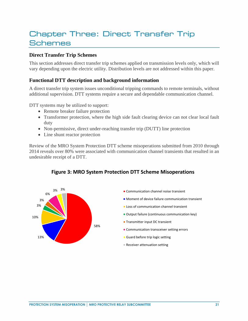
Review of the MRO System Protection DTT scheme misoperations submitted from 2010 through 2014 reveals over 80% were associated with communication channel transients that resulted in an undesirable receipt of a DTT.
58%
13%
10%
3%
3%
6%3% 3%
Figure 3: MRO System Protection DTT Scheme Misoperations
Communication channel noise transient
Moment of device failure communication transient
Loss of communication channel transient
Output failure (continuous communication key)
Transmitter input DC transient
Communication transceiver setting errors
Guard before trip logic setting
Receiver attenuation setting

PROTECTION SYSTEM MISOPERATION │ MRO PROTECTIVE RELAY SUBCOMMITTEE 22
System Protection DTT scheme misoperation root causes can be grouped into the following three categories:
Table 4 Misoperation Count: Percent:
1. DTT communication design practices: Communication channel noise transient 18 58% Loss of communication channel transient 3 10% Communication transceiver setting errors 2 6% Transmitter input DC transient 1 3%
2. DTT commissioning practices:
Guard before trip logic setting 1 3% Receiver attenuation setting 1 3%
3. DTT equipment failure:
Moment of failure transient 4 13% Output failure (continuous key) 1 3%
Total: 31 100% Whether a power line carrier, leased phone line, or microwave communication channel, DTT misoperations tend to result in an undesirable trip operation due to the receipt of an erroneous transfer trip signal. The following discussion will focus on methods available to reduce the probability of an undesirable DTT caused by one of the root causes identified above. Although there was one digital fiber optic related DTT misoperation, the cause was unknown, and further discussion within this paper will be minimal. Security Considerations
By design, a direct transfer trip is not supervised by fault sensing elements at the receiving line terminal. Therefore, the security of a DTT scheme is inherently dependent upon the integrity of the communication channel between the DTT transmitter and the DTT receiver. Unfortunately, the integrity of power line carrier, leased phone line, and microwave communication channels can be compromised by lightning strikes, electric utility faults, or other transient events. Whether the transient that caused the DTT receiver to execute an undesirable trip decision originated from the DTT transmitter or anywhere within the communication channel, there are design practices that can reduce the probability of an undesirable momentary DTT. Given that the majority of undesirable DTT trips experienced by MRO were associated with a transient condition, the following design practices focus on methods to reduce the DTT scheme’s susceptibility to momentary DTT trip ascertains, and thereby improve security. Typically, a frequency-shift keyed (FSK) carrier system is utilized for DTT applications. Modern FSK systems provide a continuous guard signal that monitors communication channel integrity, and can be designed to monitor the channel at a reduced power level in order to provide sensitive channel monitoring. Channel monitoring schemes should include SCADA indication such that timely resolution of a degraded system can be achieved.

PROTECTION SYSTEM MISOPERATION │ MRO PROTECTIVE RELAY SUBCOMMITTEE 23
PLC communication channels shall be discussed individually, whereas leased phone line and microwave communication channels shall be discussed jointly. Methods to Reduce Undesirable Trips Due to Communication Channel Noise
Given the distances a communication channel may need to travel, the possibility of a transient introducing noise into the communication channel should be considered when developing a DTT communication system. As noise in the communication channel increases, the probability of an undesirable trip increases. The following methods to reduce the probability of communication channel noise causing an undesirable trip shall be discussed:
DTT receive validation time delay Channel bandwidth (band-pass filters) Dual communication channel voting schemes Skewed hybrids
DTT Receive Validation Time Delays
A DTT receive validation time delay can be utilized to avoid undesirable momentary DTT trips caused by momentary communication channel noise. Rather than routing the DTT receive trip directly to the associated fault clearing device(s), a DTT receive validation scheme routes the DTT receive to a timer with a specified time delay pickup, and the output of the timer is then routed to the fault clearing device(s). Considering a significant percentage of communication channel transients are of a very brief duration, such as a lightning strike, a DTT receive time delay of one or two cycles can significantly improve the security of a DTT scheme. Whether an intentional DTT receive time delay is acceptable depends upon the application of the DTT scheme. A transformer that lacks a high side fault clearing device capable of clearing local fault duty may utilize a DTT scheme to clear the remote line breakers, and an intentional DTT receive time delay may not be acceptable. There may also be network locations where the risk to generator stability may also make an intentional DTT receive time delay not acceptable. However, there are many applications where DTT is utilized for breaker failure remote backup clearing, and an intentional DTT receive time delay of one or two cycles may be acceptable. In each case, engineering judgment is required. Channel Bandwidth Considerations
When designing a PLC DTT scheme, channel bandwidth can be an important consideration. Modern FSK carrier sets can be either two or three frequency. A two frequency carrier set does not utilize the center frequency, it only utilizes the shift high (fH) and shift low (fL) frequencies, with one frequency utilized for guard and the other for trip. In contrast, a three frequency carrier set utilizes the center frequency (fC) for guard, and the high and low frequencies for permissive trip (PT) or DTT. Assuming equal frequency spacing, the greater the number of frequencies utilized, the larger the channel bandwidth must be, and the greater the opportunity for noise to reduce the channel’s signal to noise ratio.
PROTECTION SYSTEM MISOPERATION │ MRO PROTECTIVE RELAY SUBCOMMITTEE 24
A two frequency carrier set can be implemented in a manner that provides greater immunity to noise than a three frequency carrier set. For example, if a 200 Hz separation between the signals utilized (fH and fL) is desired, and a 50 Hz receiver bandwidth margin above fH and below fL is also desired, the receiver bandwidth would need to be 300 Hz. In contrast, if a 500 Hz separation between fH and fL is desired, and a 50 Hz receiver bandwidth margin above fH and below fL is also desired, the receiver bandwidth would need to be 600 Hz. Therefore, for a two frequency carrier set, the greater the frequency shift, the wider the receiver bandwidth must be in order to pass the fH and fL signals. The wider the receiver bandwidth, the greater the opportunity for noise to enter the receiver and result in an undesirable DTT assertion. The same sort of process can be utilized to evaluate a three frequency carrier set. Once again, if a 200 Hz separation between the signals utilized (fH, fC and fL) is desired, and a 50 Hz receiver bandwidth margin above fH and below fL is also desired, the receiver bandwidth would need to be 500 Hz. Similarly, if a 500 Hz separation between fH and fL is desired, and a 50 Hz receiver bandwidth margin above fH and below fL is also desired, the receiver bandwidth would need to be 1100 Hz. As demonstrated, a three frequency carrier set with the same frequency spacing as a two frequency carrier set inherently requires a wider receiver bandwidth due to the number of frequencies utilized. Therefore, a two frequency carrier scheme can be designed to be more secure from noise than a three frequency carrier scheme. Given the trip from a DTT scheme is not supervised by any other logic, a DTT scheme designed with the narrowest bandwidth equipment is one method available to help minimize the noise entering the PLC receiver and the probability of receiving an undesirable DTT. Although the flexibility of modern PLC transceivers is far greater than that of older devices, there are limitations which can influence the transceiver bandwidth selection. The concepts presented within the PLC channel bandwidth discussion are similar for leased phone line and microwave channel bandwidth considerations. The significant differences compared to PLC arise due to the frequencies and hardware utilized to achieve the leased phone line and microwave communication systems. Leased phone line frequencies fall in the 300 – 4000 Hz range, while microwave communication frequencies will tend to fall in the 3 – 30 GHz range. The device utilized to interface a DTT supportive relay with a communication channel should manage the bandwidth in a manner that ensures a valid signal will be received, while rejecting as much frequency as possible. Although older technology tended to lack flexibility, modern technology typically provides significantly improved frequency and bandwidth programming flexibility. Dual communication channel DTT receive voting schemes
The security of a DTT scheme can be improved by the application of a dual communication channel voting scheme. DTT voting schemes are typically applied in conjunction with communication channels susceptible to electrical transients, such as power line carrier and audio tone. In either case, two frequency shift transmitter-receiver channel pairs are utilized to convey a trip from one facility to another. A valid DTT receive condition requires a shift from guard to trip by each of the two communication channels, thereby providing security against a communication transient appearing as a valid trip condition to one of the DTT channel receivers resulting in an undesirable trip. Depending upon the level of security or reliability desired, in the event of a channel failure, the voting scheme can be designed to either block all DTT trips (secure) or bypass the problematic DTT scheme and allow the single healthy DTT scheme to execute a trip if necessary (reliable). Refer to Figure 4 below.

PROTECTION SYSTEM MISOPERATION │ MRO PROTECTIVE RELAY SUBCOMMITTEE 25
Device: Description/Function: 85CO-1 System 1 DTT cut out switch
(On, Off, Test) DTT-1 System 1 DTT protection (Trip, Failure) 85CO-2 System 2 DTT cut out switch (On, Off, Test) DTT-2 System 2 DTT protection (Trip, Failure) 52TC Breaker trip coil Notes: 1. If more than one breaker must be
tripped, the 52 TC illustrated could be replaced by an auxiliary relay.
2. A robust steering diode is recommended.
Figure 4: Dual Channel DTT Voting Scheme Communication channel diversity can also enhance a dual channel DTT voting scheme’s security. Audio tone typically operates in a low frequency range (1200 – 4000 Hz), whereas PLC operates in a much higher frequency range (30 – 300 kHz). The probability of a noise burst affecting an audio tone and PLC communication scheme simultaneously is much less than if two audio tone or two PLC communication channels are utilized. A dual frequency PLC DTT scheme requires the use of two independent DTT transceivers, and can be designed to utilize one or two phases of a given power line, depending upon the level of reliability required. The additional PLC equipment required undoubtedly adds to the cost of implementation. Given present technology available, a dual frequency leased phone line or microwave based DTT scheme can be achieved by a single multi-channel transceiver. In either case, dual frequency DTT voting schemes should shift the upper frequency channel up and the lower frequency channel down, thereby achieving the greatest frequency separation possible for dual frequency DTT receive assertion. Typically, the greater the frequency separation the lower the probability a communication channel transient event will result in an undesirable trip. Given the diversity of DTT installations, hardware and frequency constraints may limit the ability to optimize frequency separation.
PROTECTION SYSTEM MISOPERATION │ MRO PROTECTIVE RELAY SUBCOMMITTEE 26
Given fiber optic communication channel inherent immunity to the majority of electromagnetic transients, the benefits of a dual fiber communication channel DTT voting scheme may not be worth the additional complexity introduced by the design. PLC Application of Skewed Hybrids
A hybrid is used to combine a transmitter and a receiver to a common load, such as a line tuning unit. In most PLC applications, a balanced hybrid may be appropriate. By design, a balanced hybrid has equal transmit and receive path dB losses. Long transmission lines with PLC applications can benefit from the use of skewed hybrids as long as the carrier signal budget can accommodate the additional losses. Unlike the balanced hybrid, a skewed hybrid’s transmit path has less dB loss while the receive path has more dB loss. The reduced transmit signal loss helps overcome the power line noise at the transmit end, which results in a better transmit signal-to-noise ratio. Conversely, at the receive end, the increased receive path dB loss increases both the signal and noise losses, such that the signal-to-noise ratio is not affected. The benefit of a skewed hybrid is its ability to reduce the effect of noise associated with the communication path by improving the transmit signal-to-noise ratio. Fiber Optic Digital Communications
Review of the MRO DTT communication misoperation data demonstrates a properly configured digital fiber optic communication channel is far more secure and dependable than any other type of DTT communication channel. Even though the bit error rate of a digital fiber optic channel is typically extremely small, the probability of a data error can be further reduced by requiring two bits to assert for a valid receipt of DTT message (i.e., transmit bits TXDTT1*TXDTT2 and receive bits RXDTT1*RXDTT2), rather than simply requiring only one bit to assert for a valid receipt of DTT.

PROTECTION SYSTEM MISOPERATION │ MRO PROTECTIVE RELAY SUBCOMMITTEE 27
Conclusion This paper discusses the misoperation modes of Protection System schemes observed to have a disproportionate share of misoperations within the MRO Region. This paper also identifies approaches to reduce their occurrence. The three schemes discussed were: Overcurrent Relaying, Directional Comparison Blocking Schemes, and Direct Transfer Tripping Schemes. Misoperations associated with Overcurrent Relays and Directional Comparison Blocking Schemes are often associated with external faulted elements. Reducing misoperations that occur outside of the faulted zone of protection are particularly effective in reducing risk to the BES. These misoperations are often associated with multiple outages, while misoperations during non-fault conditions typically result in the temporary loss of a single element. Many of the techniques identified for reducing misoperations fall into the category of improving human performance. Human Performance plays a crucial role both in preventing misoperations before they occur, and in improving future Protection System performance after a misoperation has been effectively mitigated. There are also significant benefits of misoperations being effectively mitigated and applied to other locations that share the same vulnerability to misoperate. This paper is intended to serve as a guide to assist entities in identifying root causes of misoperations and effectively mitigating them to lower their overall protection misoperation occurrences.

PROTECTION SYSTEM MISOPERATION │ MRO PROTECTIVE RELAY SUBCOMMITTEE 28
Additional Reference Materials Investigation and Analysis into the Misoperations Due to Carrier Holes John J. Meinardi and Miriam P. Sanders Special Considerations in Applying Power Line Carrier for Protective Relaying (IEEE Power Systems Relaying Committee Special Paper) Directional Comparison Blocking System Fundamentals Russell Patterson, Elmo Price, Miriam Sanders Guide for Protective Relay Applications to Transmission Lines (IEEE Standard C37.113-1999)

PROTECTION SYSTEM MISOPERATION │ MRO PROTECTIVE RELAY SUBCOMMITTEE 29