Embed Size (px)
Citation preview

GENERAL ELCTRICAL SPECIFICATIONS
SECTION A : MV SWITCHGEAR
SECTION B : LIGHT FITTINGS AND ACCESSORIES
SECTION C : MEDIUM VOLTAGE CABLING
SECTION D : WIRING SYSTEM
SECTION E : EARTHING PROTECTION SYSTEM
SECTION F: UNINTERRUPTED POWER SUPPLY SYSTEM
SECTION G : SPLIT TYPE AIR CONDITIONERS

SECTION A MV SWITCHGEAR
PART 1 MAIN PANELS & SWITCHBOARDS
1.0 Scope1.1 The scope of work shall cover the design, manufacture, supply, installation, testing andcommissioning of all power Totally Type Tested panels including three phase MCCBisolating switches in enclosures, suitable for 415 volts, 3-phase, 50 Hz, 4-wire systemincorporating circuit breakers of various types, bus bars, interconnections, metering,protection, earthing etc., meeting the requirements shown in schematic diagrams, scheduleof quantities and as specified.2.0 Standards2.1 All equipments, components, materials and entire work shall be carried out in conformitywith applicable and relevant Bureau of Indian Standards and Codes of Practice. In addition,relevant clauses of the Indian Electricity Act 2003 and Indian Electricity Rules 1956 asamended up to date shall also apply. Wherever appropriate Indian Standards are notavailable, relevant British and /or IEC Standards shall be applicable or any other relevantavailable International Standards.2.2 Equipments certified by Bureau of Indian Standards shall be used in this contract in linewith government regulations. Test certificates in support of this certification shall besubmitted, as required.2.3 It is to be noted that updated and current standards shall be applicable irrespective of datesmentioned with references/ standards in the tender documents.2.3.1 Some of the applicable standards are listed below:
IS 13947 : Part 1 : 1993 Specification for Low-voltage Switchgear and Controlgear -Part 1 : General RulesIS 13947 : Part 2 : 1993 Specification for Low-voltage Switchgear and Controlgear -Part 2 : Circuit BreakersIS 13947 : Part 3 : 1993 Specification for Low-voltage Switchgear and Controlgear -Part 3 : Switches, Disconnectors, Switch Disconnectors andFuse Combination UnitsIS 13947 : Part 4 : Sec 1: 1993 Specification for Low-Voltage Switchgear and Controlgear -Part 4 : Contractors and Motor-Starters - Section 1 :Electromechanical Contactors and Motor StartersIS 13947 : Part 5 : Sec 1: 2004 Low-Voltage Switchgear and Controlgear - Specification - Part5 : Control Circuit Devices and Switching Elements - Section 1 :Electromechanical Control Circuit DevicesIS 13947 : Part 5 : Sec 2: 2004 Low-Voltage Switchgear and Controlgear - Specification - Part5 : Control Circuit Devices and Switching Elements - Section 2 :Proximity Switches

IS: 3231 - 1986 Specification for Electrical Relays for Power System ProtectionIS: 11353 - 1985 Guide for Uniform System of Marking and Identification ofConductors and Apparatus TerminalsIS: 10118 (Parts 1 to 4)1982 Code of practice for selection, installation and maintenance ofswitchgearIS: 3043 – 1987IEEE Standard 80-2000 Code of Practice for earthingIEEE Guide for Safety in AC Substation GroundingIS: 732 -– 1989 Code of Practice for Electrical Wiring InstallationsIS: 5578 - 1984 Guide for marking of insulated conductorsIS: 5216 Part I & II 1982 Recommendation on Safety Procedures and Practices inElectrical WorkSP: 30 : 1985 National Electrical codeIS: 1646 - 1997 Code of practice for fire safety of buildings (general): ElectricalinstallationIS: 2075 - 2000 Ready Mixed Paint, Stoving, Red Oxide Zinc Chrome, Priming -SpecificationIS: 1248 (All Parts)2003 Direct Acting Indicating Analogue Electrical MeasuringInstruments and their Accessories -– SpecificationIS: 3618 – 1966 Specification for Phosphate Treatment of Iron and Steel forProtection Against CorrosionIS: 6005 - 1998 Code of practice for phosphating of iron and steelIS: 5 - 2004 Colours for Ready Mixed Paints and EnamelsIS 8623 : Part 1 : 1993 Specification for Low-Voltage Switchgear and ControlgearAssemblies - Part 1 : Requirements for Type-Tested andPartially Type-Tested AssembliesIS 8623 : Part 2 : 1993 Specification for Low-voltage Switchgear and ControlgearAssemblies - Part 2 : Particular Requirements for BusbarTrunking Systems (Busway)IS:8828 – 1996 Electrical Accessories - Circuit Breakers for Over Current Protection forHousehold and Similar Installations.IEC-61643, 62305,60364 Lightning & Surge ProtectionIEC-60947.7-14 Low Voltage Switchgear and Controlgear Terminal Blocks for copperconductors.2.3.2 In case of any conflict between specifications & the standards, the instructions/decision of'the Engineer' or Employer's authorized representative shall be binding.
3.0 Air Circuit Breakers3.1 Air Circuit breakers shall be air break, moulded case horizontal draw out type fullyinterlocked and meeting the requirements of Indian Standards/IEC. Breakers shall be rated
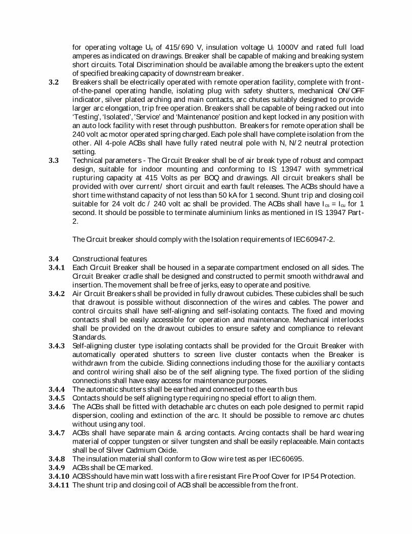
for operating voltage Ue of 415/690 V, insulation voltage Ui 1000V and rated full loadamperes as indicated on drawings. Breaker shall be capable of making and breaking systemshort circuits. Total Discrimination should be available among the breakers upto the extentof specified breaking capacity of downstream breaker.3.2 Breakers shall be electrically operated with remote operation facility, complete with front-of-the-panel operating handle, isolating plug with safety shutters, mechanical ON/OFFindicator, silver plated arching and main contacts, arc chutes suitably designed to providelarger arc elongation, trip free operation. Breakers shall be capable of being racked out into‘Testing’, ‘Isolated’, 'Service' and ‘Maintenance’ position and kept locked in any position withan auto lock facility with reset through pushbutton. Breakers for remote operation shall be240 volt ac motor operated spring charged. Each pole shall have complete isolation from theother. All 4-pole ACBs shall have fully rated neutral pole with N, N/2 neutral protectionsetting.3.3 Technical parameters - The Circuit Breaker shall be of air break type of robust and compactdesign, suitable for indoor mounting and conforming to IS: 13947 with symmetricalrupturing capacity at 415 Volts as per BOQ and drawings. All circuit breakers shall beprovided with over current/ short circuit and earth fault releases. The ACBs should have ashort time withstand capacity of not less than 50 kA for 1 second. Shunt trip and closing coilsuitable for 24 volt dc / 240 volt ac shall be provided. The ACBs shall have Ics = Icu for 1second. It should be possible to terminate aluminium links as mentioned in IS: 13947 Part-2.The Circuit breaker should comply with the Isolation requirements of IEC 60947-2.3.4 Constructional features3.4.1 Each Circuit Breaker shall be housed in a separate compartment enclosed on all sides. TheCircuit Breaker cradle shall be designed and constructed to permit smooth withdrawal andinsertion. The movement shall be free of jerks, easy to operate and positive.3.4.2 Air Circuit Breakers shall be provided in fully drawout cubicles. These cubicles shall be suchthat drawout is possible without disconnection of the wires and cables. The power andcontrol circuits shall have self-aligning and self-isolating contacts. The fixed and movingcontacts shall be easily accessible for operation and maintenance. Mechanical interlocksshall be provided on the drawout cubicles to ensure safety and compliance to relevantStandards.3.4.3 Self-aligning cluster type isolating contacts shall be provided for the Circuit Breaker withautomatically operated shutters to screen live cluster contacts when the Breaker iswithdrawn from the cubicle. Sliding connections including those for the auxiliary contactsand control wiring shall also be of the self aligning type. The fixed portion of the slidingconnections shall have easy access for maintenance purposes.3.4.4 The automatic shutters shall be earthed and connected to the earth bus3.4.5 Contacts should be self aligning type requiring no special effort to align them.3.4.6 The ACBs shall be fitted with detachable arc chutes on each pole designed to permit rapiddispersion, cooling and extinction of the arc. It should be possible to remove arc chuteswithout using any tool.3.4.7 ACBs shall have separate main & arcing contacts. Arcing contacts shall be hard wearingmaterial of copper tungsten or silver tungsten and shall be easily replaceable. Main contactsshall be of Silver Cadmium Oxide.3.4.8 The insulation material shall conform to Glow wire test as per IEC 60695.3.4.9 ACBs shall be CE marked.3.4.10 ACBS should have min watt loss with a fire resistant Fire Proof Cover for IP 54 Protection.3.4.11 The shunt trip and closing coil of ACB shall be accessible from the front.

3.5 Operating mechanism3.5.1 The Circuit Breaker shall be trip free with independent manual dual co-axial springoperated and/or motor wound dual co-axial spring operated mechanism as specified andwith mechanical ON/OFF indication. The operating mechanism shall be such that the circuitbreaker is at all times free to open immediately the trip coil is energized. The operatinghandle and mechanical trip push button shall be at the front of and integral with the CircuitBreaker.3.5.2 The Circuit Breaker shall have the following four distinct and separate positions, which shallbe indicated on the face of the panel."Service" -- Both main and secondary isolating contacts closed"Test" -- Main isolating contacts open and secondary isolating contacts closed"Isolated" -- Both main and secondary isolating contacts open"Maintenance" -- Circuit Breaker fully outside the panel ready for maintenance3.6 Circuit breaker interlocking3.6.1 Sequence type strain free interlocks shall be provided to ensure the following:a) It shall not be possible for the Breaker to be withdrawn from the cubicle when in the "ON"position. To achieve this, suitable mechanism shall be provided to lock the Breaker in thetripped position before the Breaker is isolated.b) It shall not be possible for the Breaker to be switched "ON" until it is either in the fully insertedposition or for testing purposes it is in the fully isolated position.c) It shall not be possible for the Circuit Breaker to be plugged in unless it is in the OFF position.d) A safety catch shall be provided to ensure that the movement of the Breaker, as it is withdrawn,is checked before it is completely out of the cubicle, thus preventing its accidental fall due itsweight.3.7 Anti pumping - Mechanical and electrical anti-pumping devices shall be incorporated in thecircuit breakers as required.3.8 Circuit breaker auxiliary contacts - The Circuit Breaker shall have minimum 6 NO and 6 NCauxiliary contacts rated at 16 A 415 volts 50 Hz. They shall close before the main contactswhen the Circuit Breaker is plugged in and vice versa when the Circuit Breaker is DrawnOut of the cubicle.3.9 Type Test Certificates - The ACBs shall be type tested and certified for compliance to IS:13947 from Indian testing authorities – CPRI, ERDA or international test house. Suppliershould submit certificate for the same.3.10 ACBs shall be provided with RS 485 ports for BMS (Building Management System)connectivity through MODBUS protocol.3.11 Protection – The true RMS sensing microprocessor based communication capable numericalrelease with intrinsic RS 485 port for communication by open protocol shall be provided oncircuit breaker for offering protection against overload short circuit with intentional delayand earth fault protections with intentional time delay, all with adjustable settings. Therelease shall have an LED/LCD display to show RMS current & other power parameters inall three phases and highest current / percentage loading among three phases. The releaseshould have individual fault indication by LEDs for faster fault diagnosis and reduced downtime. The release shall be self diagnostic with indication. The protection setting of releaseshall be possible to change locally from release as well as through computer with passwordduring “off” condition. It should be possible to change protection setting through computer

with password protection while ACB is carrying current. The release shall provide zoneselective interlocking for short circuit and earth fault protection zones to reduce thermalstress on the system. The release should provide fault history including cause of fault aswell as level of fault current. It should be possible to store minimum 5 last trip data withnon-volatile memory. The release should provide auto doubling facility and shall recordstarting current during switching on. Additional features of release- Ack of setting onrelease, self powered trip unit independent of communication facility, making currentrelease, phase sequence and reverse power protection.4.0 MCCBs4.1 Moulded Case Circuit Breakers shall be standard products of established manufacturers asindicated in list of approved makes best suited to the application duty and shall conform toIS 13947-2, IEC 60947-2. MCCBs shall be suitable for fault levels as specified inBOQ/drawings or higher. Upstream breakers shall be of higher kA rating compared todownstream breakers to ensure discriminated, coordinated protection of the distributionsystem. MCCB’s shall be provided in fixed type cubicles.4.2 MCCBs shall be current limiting type preferably double break with trip time of less than 10millisecond suitable for 3 phase 415 Volts AC 50 HZ supply with neutral 4P/3P/2P asrequired and rated for insulation voltage 690-750V, operating voltage of 415V for 3 Phase,Service short circuit breaking capacity (Ics) i.e Ics =25 kA up to 100A and Ics= 35 kA for therange of 125-630 Amp MCCBs and marked with suitability for isolation as specified andrequired. All Breakers/MCCBs shall incorporate front adjustable & interchangeable releasewith adjustable (40 to 100%) overloads and adjustable short circuit faults. All the MCCBsshall have electrical endurance of the order of 7000-800 operation cycles for current ratingof 100-250 amps. MCCBs shall have double insulation & release shall be EMC/EMIcompatible as per IEC 6099947-2. 4 Pole MCCBs shall have adjustable neutral setting to N,N/2.4.3 MCCB cover and case shall be made of high strength heat resisting and flame retardantthermosetting insulating material. Operating handle shall be quick make/break, trip-freetype having suitable ON, OFF and TRIPPED indicators and a common handle forsimultaneous operation of all the phases. Suitable arc extinguishing device shall be providedfor each contact. Tripping unit shall be connected by a common trip bar such that tripping ofany one pole causes three poles to open simultaneously. Contact tips shall be made ofsuitable arc resistant alloy. Terminals shall be with adequate clearances.4.4 MCCBs shall be provided with accessories as specified in the drawings and BOQ. In addition,MCCBs shall be provided with following interlocking devices with the compartment door(i) Door interlock to prevent door being opened when the breaker is in ONposition (extendable rotary handle to be invariably provided)(ii) Interlock to prevent the Breaker being switched ON with the door open4.5 MCCBs shall have ultimate breaking capacity (Icu) same as Service short circuit breakingcapacity (Ics), i.e. Icu = Ics, as also specified in the drawings and BOQ.4.6 All MCCBs shall have suitably rated minimum 2 changeover auxiliary contacts unlessspecified otherwise. All Models 3&4 Poles versions shall be of same design and make andutilization category ‘A’.4.7 MCCBs shall have trip free mechanism such that tripping command always overrides theclosing command. MCCBs shall have disconnection capability to ensure that handle does notreturn to off position in case of contacts getting welded. Compartment doors shall clearlyindicate the state of MCCB i.e. ON/OFF/TRIP MCCBs shall be provided with test function(push button or equivalent) to check the correct functionality of the MCCBs.

4.8 MCCBs to be used in conjunction with ASTS shall be motorized or motor operated toprovide trouble free successful switch over of supplies to the safe side.4.9 Each MCCB shall have a facility for padlocking in the off position.4.10 MCCBs shall have spreader links as standard feature.4.11 MCCB protection releases should be shrouded to avoid unauthorized tampering.4.12 MCCB protection releases should have(i) In-built thermal memory(ii) In-built RMS sensing(iii) Sensitive to heating effects of harmonics and improper termination4.13 MCCB shall have shrouded terminals4.14 MCCB shall be CE marked4.15 MCCB shall be type tested and certified from local testing authorities for conformance toIEC/IS standards4.16 All releases shall be tamper proof4.17 All MCCBs which are incomers or provided in separate enclosures shall be provided with RS485 ports for BMS (Building Management System) connectivity through MODBUS protocol.5.0 Switch Fuse Units & Disconnects/Isolators (Where applicable)5.1 Switch fuse units shall have quick-make, quick-break silver plated preferably double breakcontacts with operating mechanism suitable for rotary operation in the case of cubiclemounting. All switches shall be rated according to the equipment schedule or drawings andshall withstand the system prospective fault current let through. Cam operated rotaryswitches with adequate terminal adaptors up to 25A are acceptable but for all higher ratingswitch fuse units shall be heavy-duty type.5.2 Fuses shall be HRC cartridge type conforming to IS: 13703 – 1993 with a breaking capacitycorresponding to system fault level with IP 20 protection. Fuses shall be link type withvisible indication. Screw type fuses are not acceptable for any ratings.5.3 All disconnects shall consist of switch units quick-make, quick-break type with silver platedcontacts. The switches shall preferably have double breaks. The switches shall preferablyhave sheet steel enclosure, which in turn is mounted on suitable angle iron frame work. Inwet locations enclosures shall be IP56 rated. Disconnects shall have a minimum breakingcapacity of 5KA at 415 Volts.5.4 Switch contacts shall be designed with arc repelling features to extinguish the arc quickly toprovide long contact life.6.0 Isolators6.1 Isolators shall be fixed on wall, on self-supported galvanized angle iron frame work asrequired and mounted as near to the motor as possible. Where several motors are installed,isolators if required shall be provided at a central location on a common frame work withprior approval at site.6.2 Painting, earthing and labels shall be provided as generally indicating for MV Switchgearand as shown on drawings.7.0 Metering, Instrumentation & protection7.1 The metering required to be provided for each incoming feeder shall be as per the drawing& Bill/schedule of quantities. Such metering shall not be provided on the front panel of theCircuit Breaker compartment. A separate compartment shall be provided for the Meteringand Protective relays as required. Instrument testing plugs shall be provided for testing thekWH meters and relays.7.2 Current Transformers (CT)
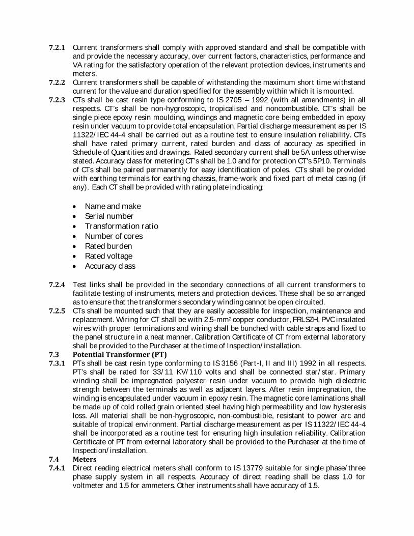
7.2.1 Current transformers shall comply with approved standard and shall be compatible withand provide the necessary accuracy, over current factors, characteristics, performance andVA rating for the satisfactory operation of the relevant protection devices, instruments andmeters.7.2.2 Current transformers shall be capable of withstanding the maximum short time withstandcurrent for the value and duration specified for the assembly within which it is mounted.7.2.3 CTs shall be cast resin type conforming to IS 2705 – 1992 (with all amendments) in allrespects. CT’s shall be non-hygroscopic, tropicalised and noncombustible. CT’s shall besingle piece epoxy resin moulding, windings and magnetic core being embedded in epoxyresin under vacuum to provide total encapsulation. Partial discharge measurement as per IS11322/IEC 44-4 shall be carried out as a routine test to ensure insulation reliability. CTsshall have rated primary current, rated burden and class of accuracy as specified inSchedule of Quantities and drawings. Rated secondary current shall be 5A unless otherwisestated. Accuracy class for metering CT’s shall be 1.0 and for protection CT’s 5P10. Terminalsof CTs shall be paired permanently for easy identification of poles. CTs shall be providedwith earthing terminals for earthing chassis, frame-work and fixed part of metal casing (ifany). Each CT shall be provided with rating plate indicating:
Name and make Serial number Transformation ratio Number of cores Rated burden Rated voltage Accuracy class
7.2.4 Test links shall be provided in the secondary connections of all current transformers tofacilitate testing of instruments, meters and protection devices. These shall be so arrangedas to ensure that the transformers secondary winding cannot be open circuited.7.2.5 CTs shall be mounted such that they are easily accessible for inspection, maintenance andreplacement. Wiring for CT shall be with 2.5-mm2 copper conductor, FRLSZH, PVC insulatedwires with proper terminations and wiring shall be bunched with cable straps and fixed tothe panel structure in a neat manner. Calibration Certificate of CT from external laboratoryshall be provided to the Purchaser at the time of Inspection/installation.7.3 Potential Transformer (PT)7.3.1 PTs shall be cast resin type conforming to IS 3156 (Part-I, II and III) 1992 in all respects.PT’s shall be rated for 33/11 KV/110 volts and shall be connected star/star. Primarywinding shall be impregnated polyester resin under vacuum to provide high dielectricstrength between the terminals as well as adjacent layers. After resin impregnation, thewinding is encapsulated under vacuum in epoxy resin. The magnetic core laminations shallbe made up of cold rolled grain oriented steel having high permeability and low hysteresisloss. All material shall be non-hygroscopic, non-combustible, resistant to power arc andsuitable of tropical environment. Partial discharge measurement as per IS 11322/IEC 44-4shall be incorporated as a routine test for ensuring high insulation reliability. CalibrationCertificate of PT from external laboratory shall be provided to the Purchaser at the time ofInspection/installation.7.4 Meters7.4.1 Direct reading electrical meters shall conform to IS 13779 suitable for single phase/threephase supply system in all respects. Accuracy of direct reading shall be class 1.0 forvoltmeter and 1.5 for ammeters. Other instruments shall have accuracy of 1.5.
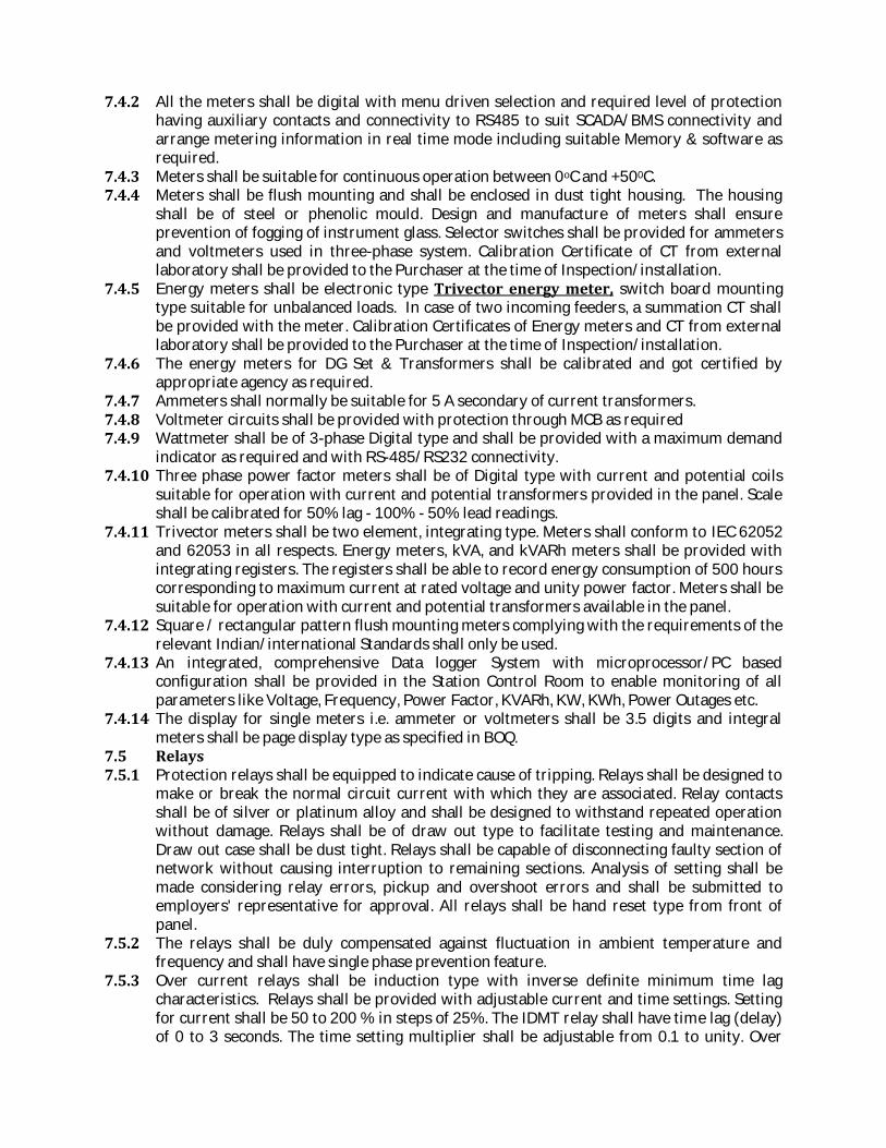
7.4.2 All the meters shall be digital with menu driven selection and required level of protectionhaving auxiliary contacts and connectivity to RS485 to suit SCADA/BMS connectivity andarrange metering information in real time mode including suitable Memory & software asrequired.7.4.3 Meters shall be suitable for continuous operation between 0oC and +500C.7.4.4 Meters shall be flush mounting and shall be enclosed in dust tight housing. The housingshall be of steel or phenolic mould. Design and manufacture of meters shall ensureprevention of fogging of instrument glass. Selector switches shall be provided for ammetersand voltmeters used in three-phase system. Calibration Certificate of CT from externallaboratory shall be provided to the Purchaser at the time of Inspection/installation.7.4.5 Energy meters shall be electronic type Trivector energy meter, switch board mountingtype suitable for unbalanced loads. In case of two incoming feeders, a summation CT shallbe provided with the meter. Calibration Certificates of Energy meters and CT from externallaboratory shall be provided to the Purchaser at the time of Inspection/installation.7.4.6 The energy meters for DG Set & Transformers shall be calibrated and got certified byappropriate agency as required.7.4.7 Ammeters shall normally be suitable for 5 A secondary of current transformers.7.4.8 Voltmeter circuits shall be provided with protection through MCB as required7.4.9 Wattmeter shall be of 3-phase Digital type and shall be provided with a maximum demandindicator as required and with RS-485/RS232 connectivity.7.4.10 Three phase power factor meters shall be of Digital type with current and potential coilssuitable for operation with current and potential transformers provided in the panel. Scaleshall be calibrated for 50% lag - 100% - 50% lead readings.7.4.11 Trivector meters shall be two element, integrating type. Meters shall conform to IEC 62052and 62053 in all respects. Energy meters, kVA, and kVARh meters shall be provided withintegrating registers. The registers shall be able to record energy consumption of 500 hourscorresponding to maximum current at rated voltage and unity power factor. Meters shall besuitable for operation with current and potential transformers available in the panel.7.4.12 Square / rectangular pattern flush mounting meters complying with the requirements of therelevant Indian/international Standards shall only be used.7.4.13 An integrated, comprehensive Data logger System with microprocessor/PC basedconfiguration shall be provided in the Station Control Room to enable monitoring of allparameters like Voltage, Frequency, Power Factor, KVARh, KW, KWh, Power Outages etc.7.4.14 The display for single meters i.e. ammeter or voltmeters shall be 3.5 digits and integralmeters shall be page display type as specified in BOQ.7.5 Relays7.5.1 Protection relays shall be equipped to indicate cause of tripping. Relays shall be designed tomake or break the normal circuit current with which they are associated. Relay contactsshall be of silver or platinum alloy and shall be designed to withstand repeated operationwithout damage. Relays shall be of draw out type to facilitate testing and maintenance.Draw out case shall be dust tight. Relays shall be capable of disconnecting faulty section ofnetwork without causing interruption to remaining sections. Analysis of setting shall bemade considering relay errors, pickup and overshoot errors and shall be submitted toemployers' representative for approval. All relays shall be hand reset type from front ofpanel.7.5.2 The relays shall be duly compensated against fluctuation in ambient temperature andfrequency and shall have single phase prevention feature.7.5.3 Over current relays shall be induction type with inverse definite minimum time lagcharacteristics. Relays shall be provided with adjustable current and time settings. Settingfor current shall be 50 to 200 % in steps of 25%. The IDMT relay shall have time lag (delay)of 0 to 3 seconds. The time setting multiplier shall be adjustable from 0.1 to unity. Over
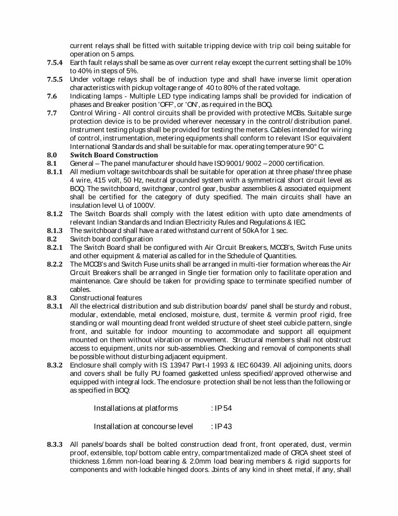
current relays shall be fitted with suitable tripping device with trip coil being suitable foroperation on 5 amps.7.5.4 Earth fault relays shall be same as over current relay except the current setting shall be 10%to 40% in steps of 5%.7.5.5 Under voltage relays shall be of induction type and shall have inverse limit operationcharacteristics with pickup voltage range of 40 to 80% of the rated voltage.7.6 Indicating lamps - Multiple LED type indicating lamps shall be provided for indication ofphases and Breaker position 'OFF', or 'ON', as required in the BOQ.7.7 Control Wiring - All control circuits shall be provided with protective MCBs. Suitable surgeprotection device is to be provided wherever necessary in the control/distribution panel.Instrument testing plugs shall be provided for testing the meters. Cables intended for wiringof control, instrumentation, metering equipments shall conform to relevant IS or equivalentInternational Standards and shall be suitable for max. operating temperature 90° C.8.0 Switch Board Construction8.1 General – The panel manufacturer should have ISO 9001/9002 – 2000 certification.8.1.1 All medium voltage switchboards shall be suitable for operation at three phase/three phase4 wire, 415 volt, 50 Hz, neutral grounded system with a symmetrical short circuit level asBOQ. The switchboard, switchgear, control gear, busbar assemblies & associated equipmentshall be certified for the category of duty specified. The main circuits shall have aninsulation level Ui of 1000V.8.1.2 The Switch Boards shall comply with the latest edition with upto date amendments ofrelevant Indian Standards and Indian Electricity Rules and Regulations & IEC.8.1.3 The switchboard shall have a rated withstand current of 50kA for 1 sec.8.2 Switch board configuration8.2.1 The Switch Board shall be configured with Air Circuit Breakers, MCCB's, Switch Fuse unitsand other equipment & material as called for in the Schedule of Quantities.8.2.2 The MCCB's and Switch Fuse units shall be arranged in multi-tier formation whereas the AirCircuit Breakers shall be arranged in Single tier formation only to facilitate operation andmaintenance. Care should be taken for providing space to terminate specified number ofcables.8.3 Constructional features8.3.1 All the electrical distribution and sub distribution boards/ panel shall be sturdy and robust,modular, extendable, metal enclosed, moisture, dust, termite & vermin proof rigid, freestanding or wall mounting dead front welded structure of sheet steel cubicle pattern, singlefront, and suitable for indoor mounting to accommodate and support all equipmentmounted on them without vibration or movement. Structural members shall not obstructaccess to equipment, units nor sub-assemblies. Checking and removal of components shallbe possible without disturbing adjacent equipment.8.3.2 Enclosure shall comply with IS: 13947 Part-I 1993 & IEC 60439. All adjoining units, doorsand covers shall be fully PU foamed gasketted unless specified/approved otherwise andequipped with integral lock. The enclosure protection shall be not less than the following oras specified in BOQ:Installations at platforms : IP 54Installation at concourse level : IP 438.3.3 All panels/boards shall be bolted construction dead front, front operated, dust, verminproof, extensible, top/bottom cable entry, compartmentalized made of CRCA sheet steel ofthickness 1.6mm non-load bearing & 2.0mm load bearing members & rigid supports forcomponents and with lockable hinged doors. Joints of any kind in sheet metal, if any, shall

be seam welded and all welding slag ground off and welding pits wiped smooth withplumber metal. All holes in metalwork shall be protected by substantial grommets orbushes to protect wiring passing through them. The maximum overall height of panels andthe maximum/minimum height of the operating handles from floor level shall be as perstandard norms.8.3.4 The frame work shall be finished with standard two coats of epoxy powder coating ofapproved color shade after necessary chemical degreasing and primer coating as perstandard 7 tank process.8.3.5 All panels and covers shall be properly fitted and secured with the frame. Fixing screwsshall enter holes tapped into an adequate thickness of metal or provided with hank nuts.Self threading screws shall not be used in the construction of the Switch Boards.8.3.6 The switchboard shall be designed for the incoming and outgoing LV feeders as per theprovisions of IS: 8623 (Part I)–1993, IS 13947:1993 and IEC Pub 947-5-1 to latest version &IEC 60439-1. Generous space shall be provided for vertical rising cables, their bending andtermination.8.3.7 The switchboard panel shall have provision for top / bottom in coming and bottom / top outgoing to suit site conditions of cable entries.8.3.8 All the cable entries shall be sealed with EPDM based modules made of Ethylene PropyleneDiene Terpolymer. The modules should below smoke Index, halogen free cross linkablerubber compound based on Ethylene Propylene Diene Terpolymer (EPDM). The systemshould be based on multidiameter and flexible technology for sealing different diameters ofcables and pipes by peeling away layers. The system should ensure full fool proof protectionagainst, water, dust, humidity, fire, vibration, temperature variations, pull tension, noise,entry of rodent as well likely damages by rodent and complying the following standards:1. Fire: UL (V-O) by Underwriters Laboratories Inc. for fire protection formore than 90 minutes.2. Environmental sealing: protection against dust, water, and penetratingsolid objects: IP 55, 66 and 67.3. Vibration, shock: Thermal cycling and fluid contamination resistance.8.3.9 The switch board / panel shall be divided into cubicles and all front doors of cubiclescontaining MCCBs shall be inter-locked so that the doors can not be opened unless theMCCB is off. Protection against shock in normal service shall be achieved by the provision ofbarriers or enclosures both vertical and horizontal and between adjacent units to ensuresegregation and prevent accidental contact with live parts, or by complete insulation of liveparts.8.3.10 The layout of the equipment and the components shall be such as to ensure creepagedistances and isolating distances specified in the latest version of IS: 8623/ IEC 60439-1.The sub-assemblies of similar equipment shall be interchangeable.8.3.11 All connections shall normally be accessible from the front side of the panel. Whereconnections are not accessible from the front, the back side shall be provided with doorswith handles and panel type locks. Required number of lifting lugs fixed on separatesections of the framework shall be provided. Two earthing studs shall be provided on theframework.8.3.12 All panels shall have digital meters connected through RS 485 port to BMS. All other BMSconnections, unless specified otherwise, shall be through potential free contacts and itshould be ensured that all such connection points are brought to one place at a suitableterminal strip duly numbered, easily accessible for the purpose. BMS wiring shall start fromthis designated terminal strip.8.4 Switchboard dimensional limitations

8.4.1 A base channel of minimum size 75 mm x 75 mm x 5 mm thick shall be provided at thebottom.8.4.2 A minimum of 200 mm blank space between the floor of switch board and bottom most unitshall be provided. The overall height of the Switch Board shall be limited to 2300 mm. Theheight of the operating handle, push buttons etc shall be restricted between 300 mm and1850 mm from finished floor level.8.5 Switch board compartmentalization - The switch boards shall be conforming to Form 4B asper IEC 60439-1. The Switch Board shall be divided into distinct separate compartmentscomprising:8.5.1 A completely enclosed ventilated dust and vermin proof bus bar compartment for thehorizontal and vertical busbars.8.5.2 Each circuit breaker, switch fuse units and MCCB (functional units) housed in separatecompartments enclosed on all sides separating it and its terminals for external conductorsfrom other such functional units.8.5.3 Sheet steel hinged lockable doors for each separate compartment provided and dulyinterlocked with the breaker/switch fuse unit in "on" and "off" position.8.5.4 Separate and adequate compartments for all Circuit Breakers provided for accommodatinginstruments, indicating lamps, control contactors and control fuses etc. These shall beaccessible for testing and maintenance without any danger of accidental contact with liveparts of the circuit breaker, busbars and connections.8.5.5 A horizontal wire way with screwed cover provided at the top to take interconnectingcontrol wiring between vertical sections.8.5.6 Separate cable compartments running the height of the Switch Board in the case of frontaccess Boards provided for incoming and outgoing cables.8.5.7 Cable compartments of adequate size for easy termination of all incoming and outgoingcables entering from bottom or top.8.5.8 Adequate and proper support provided in cable compartments to support cables.8.5.9 Inter-changeable feeder compartments for all identical feeders of same rating.8.5.10 Segregation by Metallic vertical and horizontal barriers (no Hylem /PVC) between adjacentunits or by complete insulation of all live parts. Control cables shall be segregated fromprimary conductors.8.6 Switch board bus bars8.6.1 The bus bar and interconnections shall be of electrolytic copper and of rectangular crosssections suitable for full load current for phase bus bars and half rated current for neutralbus bar as specified and shown on drawings and rated for a temperature rise of 30C overthe ambient temperature specified, based on insulated conductor rating (IS:8084-1976) andthe maximum current density for copper shall be 1.4 amp per mm2 for ratings up to 500Amp and beyond 500 amp maximum current density shall be 1.2 amp per mm2. Bus barsupporting system shall be suitable to withstand the stresses of a 31 MVA sustainedsymmetrical fault level at 415 volts for 1 second or as per schedule of quantities.8.6.2 The bus bars shall be insulated with epoxy paint. Accessible bus bar joints shall beshrouded in an approved manner. Minimum clearances between phase to phase andbetween phases and neutral (including protruding nuts and bolts if any) shall be 25 mm.Minimum clearance between phases and earth (including protruding nuts and bolts if any)shall be 20 mm.8.6.3 While providing the bus-bar section, the total load with 25% over load margin may beconsidered which may be transferred to an individual panel through the inter-connectionbetween panels in the event of failure of incoming supply to the other panels. The diversityfactor of various loads shall be taken as 1 for design purposes. The bus bar shall be designedfor easy extension in future at either end.

8.6.4 An earthing bus made of Copper/GI as approved shall be provided through out theswitchboard/panel with securely connected earthing terminals at both ends.8.6.5 Protective earthing conductor shall be as per IEC/IS & type tested. Recommended sizesrelated to the incoming feeder are as follows:
Phase conductor Protective conductorupto 16 mm2 equal size16 to 35 mm2 16 mm2over 35 mm2 50% of phase conductor8.6.6 In case of dissimilar materials the Protective Conductor shall be suitably sized for equalconductance.8.6.7 All internal wiring, busbar metering etc. shall conform to IS: 5578 – 1984 with allamendments.8.6.8 All bus bar connections in Switch Boards shall be bolted with high tensile strength SS boltsand nuts. Additional cross section of bus bars shall be provided wherever holes are drilledin the bus bars. No insulation tape shall be used in the busbars / interconnections.8.6.9 Feeder connections shall be solid copper bars duly insulated with bimetallic clampswherever required.8.6.10 Shrouds for bus bar joints /tapping points shall be fiber-glass only. Bus insulators shall beflame retardant, track resistant type with high creapage surface and non-hygroscopicmaterial such as epoxy/SMC/DMC. Busbars shall be supported and braced to withstand thestress due to max. short circuit current and also the thermal expansion8.6.11 The bus bar support shall be exactly same as used in type tests.8.7 Components installed in the assembly8.7.1 All components shall conform to respective Indian Standards or IEC specifications and shallbe suitable for the particular requirements of rated current, voltage, service life, making andbreaking capacity and short-circuit withstand strength. Co-ordination of componentmatching shall be observed. The Employer’s Representative shall be empowered to choosecompact component/ accessories as deemed fit out of the list of the approved makes.8.7.2 Separate current transformers shall be provided for each protection device and forinstrumentation.8.7.3 All assemblies of switchgear and control gear shall comply with IEC 60439 or approvedequivalent. The clearance in front, back and side of all assemblies of switchgear and controlgear shall be not less than 1.2 metres or minimum specified in standards, while switchgearconsidered in the fully drawn out condition.8.7.4 All push buttons shall be of the push to actuate type and provided with number of contactsas required.8.7.5 Control & selector switch - Control & selector switches shall be rotary type having enclosed(in removable cover) contacts, stay put maintenance type, provided with escutchean platesclearly marked to show the position.8.7.6 Auxiliary contacts including push button contacts – All main as well as auxiliary contactsshould be rated for 10A minimum.8.8 Instrument accommodation8.8.1 Instruments and indicating lamps shall not be mounted on the Circuit BreakerCompartment door. The current transformers for metering and for protection shall bemounted on the solid copper busbars with proper supports.
8.8.2 For MCCB's/SFU’s, instrument, handles and indicating lamps can be provided on thecompartment doors.8.9 Terminal arrangement8.9.1 Both incoming and outgoing cables shall have top / bottom entry depending on siterequirement.8.9.2 The marking and arranging of switchgear, bus bars, connections and small wiring shall beclear and comply with an approved international standard. Terminal blocks for low voltagewiring shall be of the rail mounted type moulded from high-grade non-hygroscopicmelamine having all live parts fully shrouded and assembled in banks with marking tags tofit into moulded tag slots.8.9.3 Terminals for final connections for indication, instrumentation and metering circuitry shallhave test probe facilities and an integral disconnecting device to facilitate testing.8.9.4 Cables are to be terminated by terminal blocks with non-ferrous terminals conforming toIEC-60947-7-1.8.10 Contactors8.10.1 Contactors shall comply with IEC 60947-4-1 and shall be of the double air break type havingan uninterrupted rated duty, and utilization category AC 6b for power factor correctioncapacitors & AC 3 for other uses with fast opening and closing type contacts.8.10.2 Contactor operating coils shall be AC suitable for the phase to neutral voltage of the supplyand shall be protected by means of a low current MCB/cartridge fuse.8.10.3 Main contactors shall be silver faced.8.10.4 Contactors shall not dropout at voltage at 70% of rated voltage and minimum pickupvoltage shall be 85% or as specified.8.10.5 The contactors for power factor correction equipment shall be of quick break and have ahigh arc resistance during switching and specifically designed for switching directlyconnected capacitor banks.8.10.6 The mechanical endurance of the contactors shall not be less than 3 million no-loadoperating cycles.8.10.7 The contactor should be modular in design, built – in mechanically interlocked, suitable foraddition of auxiliary contacts .8.10.8 Contactors should have making capacity equal to or more than 10 Ie & Braking Capacityequal to or more than 8 Ie.8.10.9 The contactors should be climate proof, capable of frequent switching with class Hinsulation and should operate without derating at 60oC.8.10.10 The rated voltage & rated insulation voltage shall be 690V. The rated impulse voltage ofthe contactor should be as per the standards.8.10.11 The control and power terminals should be at separate layers preferably with colourcoding (black for power and white for control). All contactors power connection shall befinger safe (IP 2X).8.10.12 For DC control the contactor should have wide range (0.7 to 1.25 Uc) DC coil with built ininterference suppression.8.10.13 They should be capable of being integrated into automated system (PLC’s).8.11 Wiring8.11.1 All wiring for relays and meters and other associated equipments shall be with FRLSZH,1050 class PVC insulated, stranded copper conductor wires.8.11.2 The wiring shall be colour coded and labeled with approved ferrules for identification. PVCferrules yellow in colour, locked to avoid movement & with black engraved letters shall beprovided at each end of all wires marked to correspond with equipment/circuit designation& termination numbers as specified / approved or as required.

8.11.3 A separate bunching & separate route shall be followed for AC& DC wiring.8.11.4 The minimum size of copper conductor control wires for switch-boards shall be 2.5 mm2.8.11.5 Wiring shall be terminated through cage clamps or using crimping lugs where former notfeasible, without joints or Tee on their run. Wiring shall be run on sides of panels, neatlybunched, secured without affecting equipment mounting.8.12 Cable terminations8.12.1 The Switch Boards shall be complete with supporting clamps and brackets etc fortermination of 1100 volt grade aluminium/copper conductor PVC/PVCA cables, Knockoutholes of appropriate size and number shall be provided in the Switch Board in conformitywith the location of incoming and outgoing conduits/cables. Gland plates, gland-bracketsand extension boxes shall be removable and shall be of adequate size for the particularcables to be terminated.8.12.2 The cable terminations for the MCCB’s shall be brought out to the rear in the case of rearaccess switchboards or in the cable compartment in the case of front access Switch-Boards.The Contractor shall co-ordinate the cable sizes and corresponding crimping type copperlugs for each Incomer and Outgoing feeders and correct size lugs shall be provided boltedup in the switchboard.8.12.3 Suitable sealant shall be used as described in 8.3.8.8.13 Space heaters - Not applicable8.14 Earthing8.14.1 All switch panels shall be provided with protective earthing as specified.8.14.2 A main earth bar of GI or aluminium or copper as required shall be provided throughout thefull length of the Switch Board to earth all switchgears with a provision to make connectionsto the sub-station earth’s on both sides.8.14.3 The frame of the Circuit Breaker shall be positively earthed when racked into the cubicle.Protective earthing of the switch-boards shall be connected to the building earth.8.15 Sheet steel treatment and painting8.15.1 Sheet Steel materials used in the construction of these units should have undergone arigorous rust proofing process comprising of alkaline degreasing, descaling in dilute sulfuricacid and a recognized phosphating process. The steel work shall then receive two dip-coatsof oxide filler/ primer before final painting. Castings shall be scrupulously cleaned andfettled before receiving a similar oxide primer coat. The manufacturer is required to have 7tank treatment facility for this.8.15.2 All sheet steel shall after metal treatment be powder coated with two coats of shade 692 oras approved to IS 5 on the outside and white on the inside. Each coat of paint shall beproperly stoved and the paint thickness shall not be less than 80 microns. The panelmanufacturer should have in-house power coating facility.8.16 Name plates and labels - Suitable engraved white on black name-plates and identificationlabels of metal for all Switch Boards and Circuits shall be provided. These shall indicate thefeeder number and feeder designation.9.0 Installation & Foundation9.1 The location of each foundation shall be correctly set out in accordance with the approvedfoundation layout drawing. Base channels shall be grouted, leveled in cement concrete padfor switchgear and other cubicle panels, etc. with reference to a bench mark in the building.Pedestal type panels and superstructures shall be erected by grouting foundation bolts intothe foundation in cured holes left in foundation blocks. For concreting on existing floors, aproper bonding surface shall be made by chipping the floor. The final finish to the surface ofthe floor shall be given after all equipment has been installed. If floor is broken forinstallation of equipment, it shall be restored to original finish after completion ofinstallation.

9.2 The concreting shall be done in accordance with the provision of Indian Standard Code ofPractice for Plain and Reinforced Concrete, IS: 456-2000. Concreting material shall confirmto the following:IS: 383-1970 Specification for coarse and fine aggregates from natural sourcesfor concreteIS: 269-1989 Specification for 33 grade ordinary portland cementIS: 516-1959 Method of test for strength of concrete9.3 Suitable grooves or niches shall be provided in the foundation block at the time of casting toenable embodiment of earth strips without calling for chipping of the blocks. Subsequentlyconduits of appropriate size shall be embedded in the foundation blocks for cabling, in thefirst instance, wherever required.9.4 All foundations shall be cast in the presence of the Employer's representatives. Allfoundation and grouted bolts shall be cured for a minimum period of 48 hrs.9.5 Foundations shall be prepared as per manufacturers drawing, shall be leveled, checked foraccuracy and the switchboards installed. Busbar connections shall be checked with a feelergauge after installation. Tightness of accessible bolted bus joints shall be checked usingcalibrated torque wrench. Sealing of cable and boxes to prevent moisture entry shall bechecked. Switchboard earth bars shall be connected to the protective earth system.9.6 Fabrication drawings of all panels shall be approved by the Employer's representativebefore fabrication.10.0 Testing and Inspection10.1 All switchboards shall be factory inspected by Employers’ representative before finishingand dispatch.10.2 Certificate for all routine and type tests for circuit breakers in accordance with theIS:13118-1991 shall be furnished.10.3 All panels shall be meggered phase to phase and phase to neutral using a 1000/500Vmegger with all outgoing feeders in closed position. The megger value should not be lessthan 2.5 MΩ between phases and 1.5 MΩ between phases and neutral.10.4 All meters and relays shall be calibrated and tested through secondary injection tests.10.5 All field tests shall be witnessed by authorized representative of the Employer andrecorded. The contractor shall give due prior notice. An appropriate format shall beprepared by the Contractor for this purpose. The test format shall have prior approval fromEmployer. Test results will be witnessed and signed by the Contractor and Employer’srepresentative.11.0 Tests on switch board / panels11.1 Type and Routine Test - Routine tests shall be carried out on the assembly in accordancewith IS: 8623 (Part I) – 1993. Recently concluded Type test certificates from a reputedindependent laboratory, specially those related to short circuit level and IP Protection willhave to be submitted. The switchboards shall be totally type tested assemblies as per IEC60439 & certified for internal arc as per IEC 61641 & AS 3439/1 from reputed lab.11.1.1 Type test certificates from the manufacturers for the switch board / lighting panelcomponents viz. ACBs, MCCBs, MCBs, change-over switches shall be furnished. These shallinclude following but not limited to:(i) Temperature rise of bus bars and components (not to exceed 300C )(ii) Dielectric strength of electrical parts(iii) Short circuit capacity of bus-bars and components(iv) Continuity of protective circuits(v) Mechanical operation of switchgear

(vi) Degree of protection and protective measures against direct and indirect contact(vii) Clearances and creepage distances11.2 Acceptance Tests - Following minimum tests but not limited to shall be carried out asfollows for ensuring integrity of the cable anchorage during handling and installation:(i) General visual check, including measurement of overall dimensions, location, number andtypes of devices, terminal boxes, etc.(ii) Manual and electrical operation of circuit breakers etc. andelectrical operation of contactors/automatic change-over switches.(iii) Dry insulation test with power frequency voltage.(iv) Insulation resistance of circuits.12.0 Submittals12.1 The Submittals to be submitted by the contractor for approval and before ordering forprocurement shall include following guaranteed performance particulars:(i) Switch boards/panels' Name & Make(ii) Bus Bar: i) Size, ii) Material, iii) Rated capacity, iv) Busbar supporting systemand the Short circuit with-stand capacity(iii) Moulded case circuit breakers: Rated capacity, Rupturing capacity, Make, No. ofNO/NC contacts, Conformity to Standards.(iv) Miniature circuit breakers: Rated capacity, Rupturing capacity, Conformity toStandards(v) Voltmeter & Ammeter: Make, size, Range, accuracy class, Indication type(vi) Residual current devices: Name, Make, rated capacity, Range, sensitivity,(vii) Air Circuit Breakers: capacity, rupturing capacity, Protections, Auxiliary contacts &accessories, Conformity to specifications13.0 List of Switch Boards - Switch boards and panels as per following list need be provided.The incoming & outgoing feeders, indications, metering and protection details are shown onvarious drawings as also referred in BOQ.Sr Name of Panel Loc AbbrA Main LT PANEL ASS MDBB Main DG Lighting DB ESR EPPC Main Lighting DB ESR MLPD Main Emergency (UPS) Lighting DB ESR EMLPE Air conditioning DB ESR ACPPF Fire pump panel Pump Room FPPG Water pump panel/ MCCB Enc Pump Room WPPH Light Distribution Boards Conc & PF LDBI Escalator Power PanelMCCB Enc Conc ESPPJ ACC Panels ASS ACCP

PART 2 FINAL DISTRIBUTION BOARDS /LIGHTING DISTRIBUTION BOARDS
1.0 Scope1.1 The scope of work shall cover the design, manufacture, supply, installation, testing andcommissioning of Final distribution boards as specified and shown in respective drawings.Associated minor civil works required for the erection of the DB’s such as niche in walls etc.are also included in the scope of this contract.2.0 Standards2.1 The following updated and current Indian Standard Specifications and Codes of Practice willapply to the equipment and the work covered by the scope of this contract irrespective ofthose listed.IS : 8828 - 1996 Electrical Accessories - Circuit Breakers for Over CurrentProtection for Household and Similar InstallationsIS 8623 : Part 1 :1993 Specification for Low-Voltage Switchgear and ControlgearAssemblies - Part 1 : Requirements for Type-Tested and PartiallyType-Tested AssembliesIS 8623 : Part 2 :1993 Specification for Low-voltage Switchgear and ControlgearAssemblies - Part 2 : Particular Requirements for Busbar TrunkingSystems (Busway)IS: 13947 Specification for Low-voltage Switchgear and ControlgearIS : 10118 - 1982 Code of Practice for Selection, Installation and Maintenance ofSwitchgear and ControlgearIS: 2675 - 1983 Enclosed distribution fuse boards and cutouts for voltages notexceeding 1000 V Ac and 1200 V DcIS: 5578 - 1984 Guide for marking of insulated conductorsIS: 11353 - 1985 Guide for Uniform System of Marking and Identification ofConductors and Apparatus TerminalsIS: 9926 – 1981IEC-61643,62306, 60364
Fuse wires used in rewirable type electric fuses up to 650 voltsLightning and Surge Arrestors.2.2 In addition the relevant clauses of the Indian Electricity Act 2003 and Indian ElectricityRules 1956 as amended up to date shall also apply. The installation shall generally followthe relevant Indian Standard/ Codes of Practice or the British Standard/ Codes of Practiceor IEC Standards in the absence of Indian Standard unless specified otherwise.2.1 Necessary test certificates in support of the certification shall be submitted prior to supplyof the equipment.3 Miniature Circuit Breakers
3.1 The MCBs shall be of the completely moulded design suitable for operation at 240/415Volts 50 Hz, single phase/3-phase and neutral system. MCBs shall be quick make and breaktype conforming to relevant standards. Housing shall be heat resistant and have high impactstrength. MCBs shall be flush mounting type and shall be provided with trip free manualoperating liver with ON/OFF indications

3.2 MCBs shall be provided with magnetic thermal releases for over current and short circuitprotection.3.3 MCBs shall have quick make and break non-welding self wiping silver alloy contacts ratedfor 9/10 kA short circuit at 230/415 volts in accordance with IEC 60898 and IS : 8828 -1996 as per the schedule & the drawing both on the manual and automatic operation. Eachpole on the breaker shall be provided with inverse time thermal over load andinstantaneous over current tripping elements, with trip-free mechanism. In case of multi-pole breakers, the tripping must be on all the poles and operating handle shall be common.All DP, TP and TPN miniature circuit breakers shall have a common trip bar independent tothe external operating handle.3.4 Breakers must conform to IEC 60898 with facility for locking using padlock with hasp inOFF position. Copper Pressure clamp terminals for stranded/solid conductor insertion areacceptable up to 10-mm2 size and for higher ratings, the terminals shall be suitablyshrouded.3.5 The breaking capacity shall not be less than 10 KA at 415 VAC. MCBs shall be DIN mounted.The MCB shall be Current Limiting type (Class-3). MCBs shall be classified (B,C,D ref ISstandard) as per their Tripping Characteristic curves defined by the manufacturer. The MCBshall have the minimum power loss (Watts) per pole defined as per the IS/IEC and themanufacturer shall publish the values.3.6 The terminals shall be protected against finger contact to IP20 Degree of protection.4 Earth Leakage Circuit Breaker Current Operated Type (ELCB)
4.1 System of OperationEarth Leakage Circuit Breaker (ELCB) shall conform to IEC 61008, havedisconnection facility with suitability for Isolation & shall work on the principle ofcore balance transformer. The incoming shall pass through the torroidal coretransformer. As long as the currents in the phase and neutral shall be the same,no electro motive force shall be generated in the secondary winding of thetransformer. In the event of a leakage to earth, an unbalance shall be createdwhich shall cause a current to be generated in the secondary winding, thiscurrent shall be fed to a highly sensitive miniature relay, which shall trip thecircuit if the earth leakage current exceeds a predetermined critical value.ELCB/RCCB shall be current operated independent of the line voltage, currentsensitivity of a minimum of 30 mA and a maximum of 300 mA at 240/415 volts ACand shall have a minimum of 20,000 electrical operations. ELCBs shall be immunefrom nuisance tripping due to transient overvoltages.4.2 Mechanical OperationThe moving contacts of the phases shall be mounted on a common bridge, actuatedby a rugged toggle mechanism. Hence, the closing /opening of all the three phasesshall occur simultaneously. This also shall ensure simultaneous opening of all thecontacts under automatic tripping conditions.4.3 Neutral Advance FeatureThe neutral moving contact shall be so mounted on the common bridge that, at thetime of closing, the neutral shall make contact first before the phases; and at the

time of opening, the neutral shall breaks last after allowing the phases to open first.This is an important safety feature which is also required by regulations.4.4 Testing ProvisionA test device shall be incorporated to check the integrity of the earth leakagedetection system and the tripping mechanism. When the unit is connected toservice, pressing the test knob shall trip the ELCB and the operating handle shallmove to the "OFF" position. ELCBs shall have local/ remote trip indication facility.5 Construction of Distribution Boards
5.1 The distribution equipment, as detailed in schedule of quantities and forming a part of theDistribution Boards, shall comply to the relevant Standards and Codes of the Bureau ofIndian Standards.5.2 Distribution boards shall be factory assembled boards made preferably of 2.0 mm thickCRCA sheet Box with hinged lockable spring loaded door suitable for recessed, flushmounting, totally enclosed, dust and vermin proof duly rust inhibited through a process ofdegreasing, acid pickling, phosphating and spray painted to an approved colour over a coatof red oxide primer and shall comprise of controlling miniature circuit breakers, earthleakage circuit breakers, neutral link etc as detailed in the schedule of quantities &drawings.5.3 All Cutouts/Conduit knockouts on top and bottom and covers shall be provided with PEsealed gaskets to provide minimum IP 54 degree of protection.5.4 Three phase boards shall have phase barriers and a wire channel on three sides generally asshown on approved working drawings. Neutral bars shall be solid tinned copper bars withtapped holes and cheese headed screws. For 3 phase DB’s, 3nos independent neutral barsshall be provided. All DB’s shall be internally pre-wired using copper conductor FRLSZHPVC insulated wires brought to a terminal strip of appropriate rating for outgoing feeders.5.5 Board shall meet with the requirements of IS: 2675 – 1983 and marking arrangement ofbusbars shall be in accordance with IS 5578 – 1984.5.6 Bus Bars shall be heat shrinkable PVC insulated electrical grade copper and suitable for theincomer switch rating and sized for a temperature rise of 30C over the ambient.5.7 Each board shall have two separate earthing terminals. Two earthing terminal for singlephase and 3 phase DBs shall be provided with an earth strip connecting the studs and theoutgoing earth bar.5.8 Circuit diagram indicating the load distribution shall be pasted on the inside of the DB asinstructed. Each circuit shall be clearly numbered from left to right to correspond withwiring diagrams.5.9 All the internal connections shall be with solid/multi-stranded copper conductor PVCinsulated wires with heavy duty ferrules of adequate temperature rating. All the internalconnections shall be concealed by providing a hinged protective panel to avoid accidentalcontact with live points. All outgoing equipment mounted on a frame work for easy removaland maintenance shall be connected direct to the bus bar on the live side. Knock out holes ofappropriate size and number shall be provided a top and bottom to facilitate conduitconnection.MCBs shall be provided on the phases of each circuit. Individual banks of MCB’s shall bedetached. There shall be ample space behind the backs of MCB’s to accommodate all the

wiring. All the DB’s shall be completely factory wired, with MCB busbars & interconnectingwire sets ready for connections.Appropriate cable entry holes are to be provided and sealant as described in para 8.3.8 shallbe used.5.10 All the terminals shall have adequate current rating and size to suit individual feederrequirement. The terminal block shall conform to IEC-60947-7-1 standard or any relevantequivalent standard.5.11 All circuits shall be distinctly marked/feruled with description of service installed.5.12 All the circuits shall have an independent neutral insulated wire, one per circuit, and shallbe numbered and marked.5.13 Sample of the finished DB shall be got approved by the Employers' representative beforebulk fabrication and supply.5.14 All internal components like DIN channel, Earth & Neutral bars to be protected againstaccumulation of building materials.6 Enclosure - The Enclosure system shall be IP54 duly provided with PE gasketsealing arrangement with nut free assembly

Sheet Steel Treatment and Painting6.1 Page 28, 6.1 Sheet Steel materials used in the construction shall undergo rigorousseven tank pre-treatment process comprising of alkaline degreasing, de-scaling indilute sulphuric acid and a recognized phosphating process. Any other establishedprocess of anti-rusting shall also be acceptable. The steelwork shall then receivetwo coats of oxide fill primer before final painting as specified or powder coated asper BOQ.6.2 All sheet steel as well as the angle iron frame shall after metal treatment be givenpowder coated finish painted with two coats of approved shade to IS 5 on theoutside and white on the inside. Each coat of paint shall be properly stoved and thepaint thickness shall not be less than 50 microns.
7 Name Plates and Labels7.1 Suitable engraved white on black nameplates and identification labels of metal forall Switch Boards and Circuits shall be provided. These shall indicate the feedernumber and feeder designation.8 Installation8.1 DBs shall be fixed with bottom at 1200 mm from finished floors. DBs shall be fixedproperly, fitted square with the frame and with holes correctly positioned. DBs shallbe fastened to the walls with suitable grouted studs of not less than 12-mmdiameter.8.2 All distribution boards shall be mounted on wall or recessed, with necessary angleiron framework. All mounting frames shall have one prime coat and two finish coatsafter the completion of the work. All distribution boards shall be touched up fordamaged painting.8.3 All boards shall be meggered phase to phase and to neutral using 1000/500Vmegger with all switches in closed position. The megger value should not be lessthan 2.5 MΩ between phases and 1.5 MΩ between phase and neutral.8.4 The FDB drawings of all boards shall be approved by the Employer or his Engineerbefore fabrication and the boards will be inspected before dispatch unless waived inwriting.9 Testing & Inspection9.1 Copies of type tests and routine test as per relevant specification, carried out atmanufacturer’s work shall be submitted to the Employers' representative asrequired. Wiring and connections shall be checked for continuity.9.2 Tests as required shall be performed in presence of authorized representative of theEmployers' representative for which the contractor shall give due prior notice.9.3 Test reports shall be furnished by the contractor in approved formats only.9.4 Pre-commissioning inspection:The following checks shall be carried out before commissioning distribution boardscertifying that:(i) Erection is complete in all respect including earthing.(ii) Opening in floor within and outside panels have been sealed off and all cover anddoor gaskets are intact to make the enclosure dust and vermin proof.(iii) All metering instrument have been checked and calibrated.

(iv) Indicating lamps are healthy and in proper position.(v) Ratio test of all the CTs is satisfactory.(vi) Wiring continuity and correctness are ensured in the protection and meteringcircuits.(vii) IR values have been found satisfactory and recorded for bus bars, circuit breakers,incoming and outgoing cables.(viii) Resistance of bus joints has been checked and recorded as satisfactory.PART C CO2 GAS BASED FIRE TRACE TUBE SYSTEM FOR ELECTRIC PANELS INCLUDINGAMF PANEL
1.0 Scope1.1 The scope covers supply, installation, testing and commissioning of automatic CO2flooding system complete for electrical panels with fire trace tube, cylinder, valves,and integration with fire alarm control panel for annunciation. The work shall cover:i. Providing fire trace tube inside the panels.ii. Arrangement of CO2 for flooding of the panels.iii. Audio-visual annunciation devices for indicating incidence of fire.iv. Wiring from alarm initiating devices to be above-mentioned panels withrequired conduits as per direction of engineer-in-charge.v. Any other item required to the successful commissioning of the system.vi. Providing manual arrangement for discharge of gas inside the above panels.1.2 The electrical panel fire suppression system shall be complete with CO2 gas storagecylinders of required capacities, extinguishing agent as specified, polymer fire tracetubing, filling and end-of-line adaptors, pressure switches, control equipment and allnecessary accessories and fittings to form a complete and working installation toprotect the specified areas to the approval of the engineer-in-charge.1.3 The panels to be protected shall be determined as per the approval of the engineer-in-charge.1.4 This will have an interface with Main Fire Alarm & Control Panel. In case of fire inthe concerned Panel, indication & alarm should come in Main Fire Alarm & ControlPanel.2.0 Standards2.1 The design and installation of the CO2 gas based Fire Trace tube system is based onthe latest applicable codes and also as per the manufacturer’s recommendations, therequired CO2 gas quantity is arrived as per the volume of the respective panels to beprotected. In addition, the following standards and rules and regulations shall beapplicable:(a) Fire protection manual of the tariff advisory committee, Fire InsuranceAssociation of India(b) IS: 6382 -1984 Code of Practice for Design and Installation of FixedCarbon Dioxide Fire Extinguishing System
(c) NBC Part-IV2005 National Building Code Part-IV: Fire Safety System(d) IS: 7285 -2004 Refillable Seamless Steel Gas Cylinders - Specification(e) IS: 307 – 1966 Carbon dioxide(f) Local Fire Brigade/Authority2.2 All standards mean the latest.3.0 System Features - The system shall generally comply with IS 6382 as under:3.1 The carbon-dioxide supply shall be of the high pressure type, in which the gas isstored in rechargeable containers designed to store liquefied carbon-dioxide atatmospheric temperature corresponding to a nominal pressure of 6MN/m2(60kgf/cm2) at 27C. High pressure cylinder shall hold pressurized CO2 in liquid format ambient temperature corresponding to a nominal pressure of 6MN/m2(60kgf/cm2) at 27C.3.2 The complete equipment design shall be reliable in operation. All components of theinstallation should be located, installed or suitably protected to ensure that nomechanical, chemical or other damage is possible which may render theseinoperative.3.3 All devices used in the installation shall be capable of functioning satisfactorilybetween - 29C and 65C.3.4 For enclosed tight electrical equipment, the quantity of carbon dioxide for extendeddischarge shall be sufficient to maintain carbon-dioxide concentration of at least 30%throughout the declaration period or for a minimum of 20 minutes.3.5 Quantity of carbon dioxide for initial discharge shall be as per Table 5 of IS-6382.3.6 The total amount of carbon dioxide, calculated shall be stored in a main battery ofcarbon-dioxide cylinders conforming to IS: 7285-2004. The carbon dioxide shallconform to IS: 307-1966.3.7 All cylinders in the battery shall be interchangeable.3.8 Each cylinder shall be provided with its own valve with a dip tube extending to thebottom inside the cylinder, and valve discharge head, which shall be connected to acommon manifold through high pressure connecting pipes or tubes.3.9 All carbon-dioxide cylinders in the battery and the common manifold shall bemounted and suitably supported in a rack provided for the purpose.3.10 Flexible hoses used for discharge bend shall preferably be double wire braided(perforated) rubber covered hose suitable to withstand a minimum bursting pressureof 420kgf/cm2 at 54C.3.11 All discharge heads and valves shall be designed taking into consideration the factthat liquefied carbon dioxide expands very rapidly (1 to 450) when discharged. Therequirements of minimum flow of gas and the temperature at which these arerequired to operate shall also be taken into consideration. These shall conform to IS:3224-2002.3.12 All valves under constant high pressure shall have a minimum bursting pressure ofnot less than 42MN/m2 (420kgf/cm2) and those not under constant pressure shallhave a bursting pressure of not less than 35MN/m2 (350kgf/cm2).3.13 Discharge heads and valves shall be designed to permit a minimum discharge of 85%of the carbon dioxide in the cylinder is not more than 30s at a temperature of 27 1C.

The discharge rate of carbon dioxide shall be not less than 0.68kg/s for the first 85%of the cylinder’s contents.3.14 Nozzles shall be sufficient in a number and so located that the gas discharge patternshall completely cover the enclosure.3.15 The complete distribution system shall be free from leakage when tested at apneumatic pressure of 14MN/m2 (140kgf/cm2) with all nozzle outlets closed.3.16 All sections of pipe having dead ends shall be fitted with suitable pressure reliefdevices designed to operate between 16.8MN/m2 (168kgf/cm2) and 21MN/m2(210kgf/cm2).3.17 The nozzles shall be designed and located in such a manner that an even distributionof gas will be achieved throughout the protected space and at the same time thedischarge from the nozzles shall not cause undue splashing of flammable liquids orcreation of dust clouds that might aid spread of fire.4.0 Features of Fire Trace system4.1 The system shall be simple self activating system, specifically designed forinstallation inside enclosures, cabinets and machinery housing to detectautomatically and extinguish fire at source, at its very early stage. It should besuitable for application where the potential fire risk is located within an enclosed orconfined space e.g. electrical panels etc.4.2 The system should be an automatic self-seeking fire extinguisher, which puts fireswhere they start by means of a flexible fire detection and delivery tube. The tubeshall be manufactured from specially produced polymer material to achieve thedesired detection and delivery characteristics. The system shall have capability oflinear detection i.e. detection of fire not only at a single stage point but also at anyplace along the tube’s length.4.3 This extinguishing system should be fully integrated with fire alarm system. Thesystem should offer early warning of activation and should reduce the risk ofdamage to minimum. The system should consist of a valve, connected to a cylinderand to a flexible detection and delivery system i.e. flexible tube. This tube should berouted within the equipment to be protected. In case of fire, the tube shall melt andbursts at the hottest point and the extinguishing agent is then transported throughthe Fire trace tube exactly to the origin of fire (i.e. the point of burst).4.4 The system should be simple self-activating system without human intervention andsuitable for enclosed spaces like engine room, panels.4.5 The system should have fast response - less than 10 seconds.4.6 The system should extinguish fire at early stage and should trigger automaticallyand also manually.4.7 The system should be safe against malfunction and should not need power supplyfor detection and extinguishing of fire.5.0 Technical specifications of fire trace tube.5.1 The fire trace tube should be a flexible tube made of special polymer.5.2 The tube should have OD 6mm and ID 4mm or thereabout.5.3 The fire trace tube should be red in colour (or as directed by engineer) to indicate itis part of fire protection system.5.4 The tube should be non – conductive, non- corrosive and flexible.5.5 The tube should be capable of withstanding pressure up to 20 bars.5.6 The tube under 12 bar pressure should rupture in case of fire from 5 to 45 sec

depending upon the rate of temperature.5.7 The tube must have approval for using to detect fire from loss prevention council,Lloyds register, BAM and should have registration certificate reliability from France.5.8 The tube should be routed inside the panel for detecting fire and over heat. Nodrilling, soldering or any other damaging activity will be carried out inside the panelfor fixing tube to detect the fire.5.9 The CO2 gas cylinder should have a valve which should operate automatically, incase the pressure in the Fire trace tube reduces due to fire and bursting. Thecylinder should have a different valve which is made of virgin brass with thefollowing specifications:1. The valve should be a Direct/indirect high pressure valve.2. It should operate on sensing the drop in the pressure.3. The valve should hold pressure up to 58 bar.4. The discharge flow should be kgs to 7 kgs per minute.5. The valve will have provision for connecting pressure switch, Pressure gauge, fillingin adapter.6. The cylinder will be mounted on automatic weight measurement system.6.0 Specification of weight measurement system6.1 The weight measurement system should be designed to monitor the weight of theCO2 filled cylinder. It should consist of a load cell of high quality and precision withassociated electronics and a cylinder ring for holding the CO2 cylinder in place. Theload cell shall operate in 5oC to 70°C .The temperature effect on the span should be0.006% and the effect on tare is 0.008%. The safe over load provision should be200% of the rated capacity and should be highly reliable. The system shouldmonitors CO2 gas weight on continuous basis all the time. In the event of reductionin the weight of the CO2 gas in the cylinder (either due to leakage or release of CO2gas) beyond the present limit the electronics circuitry provided in the unit shouldactivate the respective audio visual alarm unit and annunciates the in theoccurrence of fault of fire.7.0 System Operation7.1 Designed for simple installation, often very near the source of a potential fire, firetrace is a self-activating detection & suppression system that reliably suppressesfires in few seconds. In the event of fire contacting the fire trace tube, the tubebursts at the hottest point. This leads to a rapid reduction of pressure inside thetubing. This will make the differential high pressure valve fitted on the CO2 cylinderopen instantaneously and the CO2 gas stored in the cylinder will get releasedthrough the tube at the burst point into the panel.7.2 The drop of pressure in the tube followed by reduction in the weight of the CO2 gasin the cylinder due to the discharge will activate an audio-visual alarm unit whichwill be interfaced / connected with the fire alarm system.8.0 Design Criteria8.1 CO2 gas based fire trace tube system is proposed for the protection of all the majorcontrol panels. The gas system proposed is a direct release low-pressure system

with UL & FM approval. The required CO2 gas quantity and size of the cylinder isselected based on the volume of the protected panel.9.0 Main components of the system9.1 The main features of the system are:i. Automatic detection of fireii. Automatic flooding of carbon dioxideiii. Activation of audio visual alarm unitiv. Manual release value optionv. Indication & alarm in main fire alarm & control panel9.2 The detection of fire is primarily made by a polymer tube, which can detect the fireanywhere along its length. The tube is highly flexible and can be conveniently routedto cover the various hazard areas in electrical panels.9.3 The polymer tube shall be a fixed temperature sensing tube made up of a high techpolymer material to cater to long term leak resistance, flexibility accurate andconsistent heat sensitivity. One end of the fire trace tube is connected to the CO2cylinder and the other end to a end of line adaptor through a non return value. TheCO2 cylinder assembly is mounted on a weight monitoring system.9.4 Pressure switch is connected to the end-of-line adaptor, which is electricallyconnected to an audio visual alarm unit.9.5 In the event of fire contacting the fire trace tube, the tube starts melting and burst atthe hottest point. This leads to a rapid reduction of pressure inside the tubing. Thiswill make the differential pressure valve fitted on the CO2 cylinder open outinstantaneously and the CO2 stored in the cylinder will get released through the tubeat the burst point into the panel.9.6 The drop of pressure in the tube followed by reduction in the weight of the CO2 incylinder due to the discharge will activate an audio-visual alarm both at the audiovisual alarm unit located in the respective zones.10.0 Accessories10.1 The system shall include but not limited to the following:
Fire trace tube Indirect high pressure valves D/I adapters Pressure switches Spring top Auto weigh measurement system Alarm units Non-sensing tube Manual actuation units CO2 cylinder CO2 discharge nozzles Hardware items Pressure switch to sense the drop in pressure. Filling in adapter to change the tube. Ball valve for closing and releasing. The spring top to protect the Fire trace tube at the cylinder end.

Straight fitting for connecting Fire trace tube in case of need. Cross fittings T fittings. Cross panel fittings. End of line adapter. Non return valves.All these accessories shall be supplied along with Fire trace tube for installation.
SECTION B LIGHT FITTINGS AND ACCESSORIES
1.0. SCOPE
1.1. Scope of work under this section shall include inspection at suppliers/manufacturer'spremises, appropriate, receiving at site, safe storage, transportation from point of storageto point of erection and erection of light fittings, fixtures and accessories including allnecessary supports, brackets, down rods and painting as required. The contractor shall

supply all materials and accessories (other than those supplied by the Client), labour, tools,transportation, scaffolding etc., required for the completion of above work in all respects.Type of fixtures / lamps shall be as specified in the BOQ.1.2. STANDARDS APPLICABLE:1.2.1. The lighting and their associated accessories such as lamps, reflectors, housings, ballastsetc., shall comply with the latest applicable standards, more specifically the following:
Electric light fittings General and safety requirements - IS - 1913.Industrial lighting fittings with metal reflectors - IS - 1777Decorative lighting outposts - IS - 5077Flood Lights / Metal Hallide lamps. - IS - 1947Luminaries for street lighting - IS - 2149Bayonet lamp holders - IS - 1258Bi-pin lamp holders for tubular fluorescent lamps - IS - 3323Ballasts for use in fluorescent light fittings - IS - 1534Starters for fluorescent lamp - IS - 2215Ballast for HP MV lamps - IS - 6616Capacitors for use in fluorescent, HPMV & LP sodiumVapour lamps circuits - IS - 2215Tubular Fluorescent lamps/Compact Fluorescent - IS - 2418 (Part I)Lamps (CFL)High pressure mercury vapour lamps - IS - 2183Tungsten filament general electric lamps - IS - 418High pressure sodium vapour lamps - IS - 9974 (Part -I)Ceiling Fans IS: 374Exhaust Fan IS: 2312

1.3. Light Fittings - General Requirements:a) Fittings shall be designed for continuous trouble free operation under atmosphericconditions, reduction in lamp life or without deterioration of materials and internalwiring. Outdoor fittings shall be weather - proof and rain proof.b) Fittings shall be so designed as to facilitate easy maintenance including cleaning,replacement of lamps/starters etc.c) All fittings shall be supplied complete with lamps. All mercury vapour and sodium vapourlamp fittings shall be complete with accessories like ballasts, power factor improvementcapacitors, starters, etc. Out door type fittings shall be provided with weather proof boxes.d) Fluorescent lamp fittings shall be complete with all accessories like electronic ballasts etc.e) Each fitting shall have a terminal block suitable for loop-out connection by 1100 VFRLSZH PVC insulated copper conductor wires unto 4 mm2. The internal wiring should becompleted by the manufacturer by means of FRLSZH PVC insulated standard copper wire,shall be of heat resistant type and terminated on the terminal block.f) All hardware used in the fitting shall be suitably plated or anodised and passivated for usein industrial plants.g) Earthing each light fitting shall be provided with an earthing terminal. All metal or metalenclosed parts of the housing shall be bonded and connected to the earth terminal so as toensure satisfactory earthing continuity throughout the fixture.h) Painting/Finish All surfaces of the fittings shall be thoroughly cleaned and degreased andthe fittings shall be free from scale, rust, sharp-edges, and burrs.i) The housing shall be stove-enamelled or anodised as required. The surface shall bescratch resistant and shall show no sign of cracking or flaking when bent through 90 deg.over 12 mm dia mandrel. The enclosure degree of protection shall be IP54 for indoor andweather proof IP 65 for out door.

j) All the components including the internal wiring of the luminaries to be used shall bemanufactured of material, which are of low smoke and zero halogen type. All luminairesshall be manufactured to relevant sections of IEC60598 or other approved internationalstandards and the type tests for all luminaries shall be provided.k) Luminaires should operate at ± 6% voltage fluctuation for continuous use to comply to IEC.PF > 0.95 for HF ballasts; for EM circuits PF > 0.85 with capacitor.
2.0 DECORATIVE TYPE FITTINGS
2.1 Decorative fluorescent fittings shall be provided with mounting/housing channel cumreflectors of CRCA sheet steel. Stove enamelled diffusers or louvers shall be translucentwhite polystyrene.3.0 ACCESSORIES FOR LIGHT FITTINGS REFLECTORS:
3.1. The reflectors shall be made of CRCA sheet steel/aluminium/silvered glass/Chromiumplated sheet copper as required. The thickness of reflectors shall be as per relevantstandards. Reflectors made of steel shall have stove enamelled/vitreous enamelled/epoxycoating finish. Aluminium used for reflectors shall be anodised/epoxy stoveenamelled/mirror polished. The finish for the reflector shall be as specified. The reflectorsshall be free from scratches blisters and shall have a smooth and glossy surface havingno premium light reflecting coefficient. Reflectors shall be readily removable from thehousing for cleaning and maintenance with minimum use of tools.3.2. LAMP/STARTERS HOLDERS:
3.2.1. Lamp holders shall have low contact resistance, shall be resistant to wear. They shall holdlamps in position under normal conditions of shock and vibration prevalent in an industrialatmosphere. Lamp holders for fluorescent lamps shall be of spring loaded BI-pin rotarytype. Live parts of the lamp holder shall not be exposed during insertion or removal of thelamp or after the lamp has been taken out.3.2.2. Lamp holders for incandescent and mercury vapour lamps shall be bayonet type up to 100W and Edison screw type for higher wattage. Starter holders for fluorescent lamps shall beso designed that they are mechanically robust and shall be capable of withstandingshocks during transit, installation and use.3.3. ELECTRO MAGNETIC BALLASTS FOR HID LAMPS:

3.3.1 The ballasts shall be designed for long life and low power loss. They shall be mounted usingself-locking, anti-vibration fixtures and shall be easy to remove without demounting thefittings. The enclosures shall be dust tight and non-combustible. Ballasts shall be inductive,heavy duty type, filled with thermosetting, insulating, moisture repellent polyestercompound filled under pressure or vacuum. Ballasts shall be provided with taps to set thevoltage. The ballast wiring shall be of copper and they shall be free from dust.3.3.2 Separate ballast shall be provided in case of multi lamp fittings, except in case of 2 x 20 Wfittings. Starters shall have bi-metal electrodes of high mechanical strength. Starters shall bereplaceable without disturbing the reflector of lamps and without use of any tool. Startersshall have brass contacts and radio interference suppression capacitor.3.4. ELECTRONIC BALLASTS FOR FLUORESCENT LAMP / CFL LAMPS:
1. Ballast shall be high frequency electronic type, operating lamps at a frequency of 20 kHz orhigher with no detectable flicker.2. All equipment shall confirm with the objective of the European Directives on EMC(89/336/EEC) and where appropriate shall be fixed with CE mark. It shall also comply toElectromagnetic Compatibility Emission IEC 60555 & EN55015.3. The radio frequency interference (RFI) levels generated by the electronic ballasts andcontrol gear shall be in accordance with the requirements of standard EN55015 or otherinternational standards as stated in specifications.4. Ballasts for linear fluorescent lamps: power factor shall be according to manufacturers’recommendation and type of luminaire. Input volt shall be 240V, 50Hz. Voltage tolerance:180 - 270V, with Tolerance Of Performance: +6% to 8% --- 202 to 254 V & with ToleranceOf Safety: ±10% --- 198 to 264 V.5. All ballast shall be capable of starting lamps at ambient temperature of 0 °C and above.6. Light output regulation: ballast shall maintain constant light output of all fluorescent lampsover operating ranges of 170Volts to 265 Volts. Luminous flux should not change more than±2%.

7. Relative Light Output: (percentage of light emitted compared with reference tube andballast) shall not be less than 95% and more than 100%.8. Input total harmonic content shall not exceed 10%. Ballast shall withstand line transients asper IEC 61547. Ballast case temperature shall not exceed 25 degree rise over 43 degreeambient. Ballast power factor shall be 95% or above. Ballast shall provide continuousheating voltage to lamp cathode and operate lamps on a rapid start circuit unless otherwisementioned.9. The following general lamp parameters shall be applicable unless otherwise specified inspecific design data;Compliances and approvals as per following standards or relevant Indian/InternationalStandardsa. RFI <30MHz --- EN 55015b. RFI > 30MHz --- EN 55022c. Harmonics --- EN 61000-3-2d. Immunity --- EN 61547e. Safety --- EN 61347-2-3f. Performance --- EN 60929g. Vibration & bump test --- IEC 68-2-6Fc, IEC 68-2-9Ebh. Quality standard --- ISO 9001i. Environment standard --- ISO 14001j. Approvals marks --- Safety marks
3.5. CAPACITORS:
3.5.1. The Capacitors shall have a constant value of capacitance and shall be connected across thesupply of individual lamp circuits. The capacitor shall have a value of capacitance so as tocorrect the power factor of its corresponding lamp circuit to 0.95 lag or better. Capacitorshall be hermetically sealed preferably in a metal enclosure to prevent seepage ofimpregnate and ingress of moisture.3.6. LAMPS:
3.6.1. Incandescent lamps shall be clear type unless otherwise specified. Fluorescent lamps shallbe of High lumen output type with 3350 lumen for 1200 mm, 36W lamp with colourRendering Index Ra > 80 and colour temp of 4000K with mercury content not more than 3mg. The average life shall be in excess of 15000 hours.

3.6.2. Mercury vapour lamps shall be of high pressure, colour corrected type. Lamps shall becapable of withstanding vibrations prevalent in an industrial atmosphere, thefilament/electrodes shall not break under such circumstances.3.6.3. Compact Fluorescent lamps shall be energy effective compact single ended light sourcesconsisting of two narrow glass tubes welded together. The lamp shall be complete withintegral glow switch starter and capacitor and two pin electrical connection Thelamp shall be with colour rendering index Ra > 80 and colour temp of 4000K. Thecompact lamp shall have a long life and shall be energy efficient.3.6.4. Ceramic Discharge Metal halide lamp (CDM) shall be with excellent colour rendering indexRa>80 and colour temp of 4200K. The lamp shall be with UV block Quartz outer bulb toreduce heat output.4.0 INSTALLATION:
4.1. The light fixtures and fittings shall be assembled and installed in position complete andready for service, in accordance with details, drawings, manufacturer's instructions and tothe satisfaction of the Construction Manager. Pendent fixtures specified with overall stemlengths are subject to change and shall be checked with conditions on the job and installedas directed. All suspended fixtures shall be mounted rigid and fixed in position inaccordance with drawings, instructions and the approval of the Engineer. Fixturesshall be suspended true to alignment, plumb, level and capable of resisting all lateral andvertical forces and shall be fixed as required.4.2. All suspended light fixtures, fans etc, shall be provided with concealed suspensionarrangement in the concrete slab/roof members. It is the duty of the Contractor to makethese provisions at the appropriate stage of construction. Exhaust fans shall be fixed atlocation shown on drawings. They shall be wired to a plug socket outlet at a convenientlocation near the fan. All switch and outlet boxes, for fans and light fittings shall be bondedto earth. The recessed type fixtures shall not be supported into the false ceiling frame work.This shall have independent support from the socket of ceiling using G.I. conduit downrods/chromium Plated steel chain with provision for adjusting the level of fitting. Wiresshall be connected to all fixtures through connector blocks. Wires brought out fromjunction boxes shall be encased in flexible pipes for connecting to fixtures concealed insuspended ceiling. The flexible pipes shall be check-noted to the junction box with a brassbush and double checkout at the fixture and flexible pipes, wherever used shall be ofmake and quality approved by the Engineer.5.0 MEASUREMENT
5.1. MODE OF MEASUREMENT IS AS FOLLOWS:

5.2. Installation of light fittings with all associated works including fixing accessories ismeasured in numbers (No) Supply and installation of down rods and C.P. Chain withassociated works as per SOQ and specifications are measured in linear metre (Rm).

SECTION C MEDIUM VOLTAGE CABLING
1.0 Scope1.1 The scope of work shall cover supply, laying, connecting, testing and commissioningof low and medium voltage power and control cabling.2.0 Standard2.1 All equipment, components, materials and entire work shall be carried out inconformity with applicable and relevant Bureau of Indian Standards and Codes ofPractice, as amended up to date and as below. In addition, relevant clauses of theIndian Electricity Act 2003 and Indian Electricity Rules 1956 as amended up to dateshall also apply. Wherever appropriate Indian Standards are not available, relevantBritish and /or IEC Standards shall be applicable.2.2 It is to be noted that updated and current standards shall be applicable irrespectiveof dates mentioned along with ISs in the tender documentsIS:1554 (Part-I)– 1988 PVC insulated (heavy duty) electric cables: Part 1 Forworking voltages up to and including 1100 VIS:7098 Part-I1988 Cross-linked polyethylene insulated PVC sheathed cables:Part 1 For working voltage up to and including 1 100 VIS 1255 –1983 Code of practice for installation and maintenance of powercables up to and including 33 kV ratingIS 8130 –1984 Conductors for insulated electric cables and flexible cordsIS 10418 –1982 Drums for electric cablesIS 10810 Methods of test for cables (All latest)IS 3961 Recommended current rating for cables (All latest)IS 5891–1970 Recommended short circuit rating of high voltage PVCcablesBS:7671 - 2001 Requirements for electrical installations. IEE WiringRegulations - Sixteenth edition2.3 All codes and standards mean the latest. Where not specified otherwise theinstallation shall generally follow the Indian standards/British Standards Codes ofPractice/IEC standards in order of preference where options are available2.4 Cables up to size 16/25-mm2 conductor size shall be copper conductor & beyondsize 16/25-mm2 shall be aluminum. All conductors shall be stranded3.0 Delivery, Storage and Handling3.1 All cables shall be new without any kinks or damage marked with manufacturer'sname, insulating material, conductor size and voltage class on cable surface at every600mm approx.3.2 Cable drum conforming to IS: 10418 shall be stored on a well drained, well-ventilated area protected from sun and rain on hard surface, preferably of concrete,so that the drums do not sink in ground causing rot and damage to the cable drum.3.3 During storage, periodical rolling of drums, in the direction of arrow marked on thedrum, shall be done once in 3 month through 90o. Both ends of cables shall be

properly sealed to prevent moisture ingress.3.4 Drums shall always be rested on the flanges and not on flat sides. Movement ofdrums shall always be in direction of the arrow marked on the drum. Fortransportation over long distance, the drums shall either be mounted on drumwheels, trailers and pulled by ropes, unloaded preferably by crane and rolled downcarefully on suitable ramps. While transferring cable form one drum to another, thebarrel of the new drum shall have diameter not less than the original drum4.0 Cables4.1 PVC Cables4.1.1 Medium voltage cables shall be aluminium/copper conductors PVC insulated, PVCsheathed with flame retardant low smoke zero Halozen (FRLSZH) compound andarmoured conforming to IS:1554 Part-I. Cables shall be rated for 1100 Volts.Conductors shall be insulated with high quality PVC base compound4.1.2 The conductor of all cables form shall be stranded. Sector shaped strandedconductors shall be used for cables of 50-mm2 and above.4.2 XLPE Cables4.2.1 The cables shall be 1100 Volt grade XLPE insulated with PVC inner sheath steelarmouring and with an outer protective sheath of flame retardant low smoke zeroHalozen (FRLSZH) compound, conforming to IS: 7098 (Part I). Cables shall have highconductivity stranded aluminium or copper conductors and cores colour coded tothe Indian Standards.4.3 A common covering (bedding) shall be applied over the laid up cores by extrudedsheath of unvulcanised compound. Armouring shall be applied over this extrudedsheath. The outer sheath shall bear the manufacturer’s name and trade mark atevery meter length. Cores shall be provided with following colour scheme of PVCinsulation1 Core : Red/Black/Yellow/Blue2 Core : Red and Black3 Core : Red, Yellow and Blue3 ½ /4 Core : Red, Yellow, Blue and Black4.4 Fire Survival Cable for emergency circuits4.4.1 All cables used for fire and life safety systems shall have a 3-hour fire survivalcapability. These cables may be mineral insulated or EPR insulated with mica-taping. Cables shall be tested and stamped for fire survival duty and necessarycertificates shall be furnished with each lot of supply.5.0 Installation5.1 While shortest practicable route shall be preferred, cable runs shall follow fixeddevelopment such as roads, footpaths etc. with proper offsets so that futuremaintenance and identification are rendered easy.5.2 Whenever cables are laid along well demarcated or established roads, the LV/MVcables shall be laid further from the line than HV cables.5.3 Cables of different voltages and also power and control cable shall be kept indifferent trenches with adequate separation. Where available space is restricted,LV/MV cables shall be laid above HV cables.5.4 Where cables cross one another, the cables of higher voltage shall be laid at a lower

level than the cables of lower voltage.5.5 Power and communication cables shall as far as possible, cross at right angles.Where power cables are laid in proximity to communication cables the horizontaland vertical clearances shall not normally be less than 600 mm.5.6 Cables shall be laid in the routes marked in the drawings. Where the route is notmarked, the contractor shall mark it out on the working drawings after deciding inconsultation with Employer’s representative. Cables shall be laid in masonrytrenches, directly on walls / ceiling, inside shafts / cable trays, directly buried inground or in pipes/ducts as elaborated below. Cables of different voltages and alsopower and control cables shall be laid in different trenches with adequateseparation. Wherever available space is restricted such that this requirement cannot be met, medium voltage cables shall be laid above HT cables as approved.5.7 Single cables laid shall be fixed directly to walls or ceiling and supported at not morethan 600 mm. Cables laid in built-up trenches shall be on GI supports/ Cable trays.5.8 Cables shall be so laid that the maximum bending radius is 12 times the overalldiameter of the cable for medium voltage cables and 15 times the overall diameterfor 11 kV cables or in accordance with the manufacturer’s recommendationswhichever is higher.5.9 In the case of cables buried directly in ground, the cable route shall be parallel orperpendicular to roadways, walls etc. Cables shall be laid in an excavated, gradedtrench, over a sand or soft earth cushion to provide protection against abrasion.Cables shall be protected with brick or cement tiles as shown on Drawings. Width ofexcavated trenches shall be as per code of practice and drawings.5.10 The general arrangement of cable laying shall be as per drawings. All cables shall befull runs from panel to panel without any joints or splices.5.11 Cables laid in Masonry Trenches5.11.1 Wherever so specified, cables shall be laid in indoor/outdoor masonry/RCCtrenches with chequered plate/RCC covers to be provided by contractor. Cablesshall be laid on GI supports/ Cable trays of approved design grouted in trench wallsat intervals not exceeding 600 mm. If required, cables shall be arranged in tierformation inside the trench. Cables shall be dressed properly so that the clearspacing between the cables shall not be less than the diameter of the cable. Suitableclamps, hooks and saddles shall be used for securing the cables in position.Complete details of this support work shall be shown in working drawings to beprepared by the Contractors and submitted for approval of Employer'srepresentative before execution. Works shall be carried out only as per approvedworking drawing. Wherever so specified, trenches shall be filled with fine sand.5.12 Cable laid On Trays/Walls5.12.1 Where a number of cables are run, necessary perforated/ ladder cable trays shall beprovided wherever shown. Ladder cable trays shall be galvanized MS as specified inthe BOQ.5.12.2 Cables shall be secured in position and dressed properly by means of suitableclamps, hooks, saddles etc. Clamping of cables shall be at minimum intervals asbelow:Type ofCables
Size Clamping by Fixingintervals

MV Up to and including 25-mm2 Purpose made, approved GIclamp minimum 2 mm thick,19 mm wide 300 mmMV & HV 35-mm2 to 120-mm2 Clamps 3 mm thick 25 mmwide - 600 mmMV & HV 150-mm2 and above Clamps 3 mm thick 40 mmwide - 600 mmNote : The fixing intervals specified apply to straight runs. In the case ofbends, additional clamping shall be provided at 30 cm from the center of the bend onboth sides.
5.13 Buried Directly in Ground5.13.1 Cables should be so laid that they will not interfere with under ground structures.5.13.2 All water pipes, sewage lines or other structures which become exposed byexcavation shall be properly supported and protected from injury until the fillinghas been rammed solidly in places under and around them. Cables shall be laid andprotected at such locations.5.13.3 Any telephone or other cables coming in the way are to be properly shielded asdirected by Employer's representative.5.13.4 Surface of the ground shall be made good so as to conform in all respects to thesurrounding ground to the satisfaction of Employers' representative.5.14 Cable trays5.14.1 Cable trays of sizes as per BOQ and drawings shall be of doubled bend channeldesign unless otherwise stated. Cable trays shall be fabricated from minimum 2 mmthick sheet steel and shall be complete with tees, elbows, risers, and all necessaryhardware. Trays shall be galvanized or painted as specified. Cable trays shall beerected in perfect level and plumb and shall comply with the following:5.14.2 Trays shall not have sharp edges, burrs or projections injurious to cable insulation.Trays shall include fittings such as bends, risers etc. for changes in direction andelevation. Each run of cable tray shall be completed before laying of cables. Cabletrays shall be exposed and accessible.5.14.3 Trays shall be supported adequately at minimum 1 m distance from the buildingstructure by means of painted / galvanized (as specified) MS structural memberssecured to the structure by dash fasteners or by grouting. This support should becapable of withstanding the weight equivalent of 3m length of the cables that can belaid in the trays. At turns the support has to be double and at both ends of the bend.The entire cable tray system shall be rigid. Cost of support arrangement shall beincluded in the rates quoted for supply and installation of trays unless separatelyprovided for in the BOQ. Complete details of this support arrangement shall beshown in working drawings to be prepared by the Contractors and submitted forapproval of Employer's representative before execution. Works shall be carried outonly as per approved working drawing.Minimum support should be 40 x 6mm angle. Anchor fasteners of Hilti / Fischer make ofsuitable size (not less than 12mm) to be provided.5.15 Routing of the Cable Runs5.15.1 Before cable laying work is undertaken, the route of the cables shall be decided in

consultation with the Employers' representative.5.15.2 While shortest practicable route shall be preferred, cable runs shall follow fixeddevelopment such as roads, footpaths etc with proper offsets so that futuremaintenance and identification are rendered easy.5.15.3 Whenever cables are laid along well demarcated or established roads, the LV/MVcables shall be laid further from the kerb line than HV cables.5.15.4 Cables of different voltages and also power and control cables shall be kept indifferent trenches with adequate separation. Where available space is restricted,LV/MV cables shall be laid above HV cables.5.15.5 Where cables cross one another, the cables of higher voltage shall be laid at a lowerlevel than the cables of lower voltage.5.15.6 Power and communication cables shall as far as possible cross at right angles.Where power cables are laid in proximity to communications cables the horizontaland vertical clearances shall not normally be less than 600 mm5.16 Width of Trench5.16.1 The width of trench shall be determined on the following basis:(i) The minimum width of masonry trench for laying single cables shall be 350mm or as specified in BOQ.(ii) Where more than one cable is to be laid in the same trench in horizontalformation, the width of trench shall be increased such that the inter-axialspacing between the cables except where otherwise specified shall be at leastone cable diameter .5.16.2 There shall be a clearance of at least 150 mm between axis of the end cables and thesides of the trench.5.16.3 The space between multiple cables laid in same trench shall be laid as prescribed bythe manufacturer of the cable or as recommended in standards.5.17 Depth of Trench5.17.1 Where cables are laid in single tier formation, in ground the total depth of the trenchshall not be less than 750 mm for cables up to 1.1 kV and 1250 mm for cables above1.1 kV. When more than one tier of cables is unavoidable and vertical formation oflaying is adopted, the depth of trench shall be increased by 300 mm for eachadditional tier to be formed.5.18 Excavation Of Trenches in Ground5.18.1 The trenches shall be excavated in reasonably straight lines. Wherever there is achange in direction, suitable curvature of 12 times the overall diameter of thelargest MV cable and 15 times the overall diameter for 11 kV HT cable shall beprovided. Where gradients and changes in depths are unavoidable, these shall begradual. Excavation should be done by any suitable manual or mechanical means.Excavated soil shall be stacked firmly by the side of the trench such that it may notfall back into the trench.5.18.2 Adequate precautions shall be taken not to damage any existing cables, pipes orother such installations during excavation. Wherever bricks, tiles or protectedcovers or bare cables are encountered, further excavation shall not be carried outwithout the approval of the Employers' representative. The Contractor shall use acable detector along the route of excavation and identify existing live cables alongthe route and exercise caution during excavation.5.18.3 Existing property exposed during trenching shall be temporarily supported or

propped adequately as directed by the Employers' representative. The trenching insuch cases shall be done in short lengths, necessary pipes laid for passing cablestherein and the trench refilled as required. If there is any danger of a trenchcollapsing or endangering adjacent structures, the sides shall be well shored up withtimbering and / or sheathing as the excavation proceeds. Where necessary thesemay even be left in place when backfilling the trench.5.18.4 Excavation through lawns shall be done in consultation with the Employer'srepresentative. Bottom of the trench shall be level and free from stone, brick, etc.The trench shall be provided with a layer of clean dry sand cushion of not less than80 mm in depth before laying of cables.5.19 Laying Of Cable in Trench in Ground5.19.1 The cable drum shall be properly mounted on jacks or on a cable wheel at a suitablelocation. It should be ensured that the spindle, jack etc are strong enough to carrythe weight of the drum without failure and that the spindle is horizontal in thebearings so as to prevent the drum creeping to one side while rotating.5.19.2 The cable shall be pulled over rollers in the trench steadily and uniformly withoutjerks or strains. The entire cable length shall, as far as possible, be laid in onestretch. However when this is not possible the remainder of the cable shall beremoved by flaking i.e. making one long loop in the reverse direction.5.19.3 After the cable is uncoiled and laid over the rollers, the cable shall be lifted slightlyover the rollers beginning from one end by helpers standing about 10 meters apartand drawn straight. The cable should then be taken off the rollers by additionalhelpers lifting the cables and then laid in the trench in a reasonably straight line.5.19.4 For short runs and cable sizes up to 50-mm2 1.1 kV grade, the alternative method ofdirect handling can be adopted with the prior approval of the Employer’srepresentative. If two or more cables are laid in the same trench, care should betaken to preserve relative position. All the cables following the same routes shall belaid in the same trench. Cables shall not cross each other as far as possible. When thecable has been properly straightened, the cores shall be tested for continuity andinsulation resistance. The cable shall be measured thereafter.5.19.5 Suitable moisture sealing compound / tape shall be used for sealing of the ends ofcables laid in the trench. All the cables remaining in drums after laying shall besealed in a dust and moisture proof manner.5.19.6 The trench shall be provided with a layer of clean dry sand cushion of not less than80 mm in depth before laying of cables. Cable laid in trenches in a single tierformation shall have a covering of clean dry sand of not less than 170 mm above thebase cushion of sand before the protective cover is laid. If additional tiers areformed each of the subsequent tiers also shall have a sand cushion of 300 mm andthe top most cable shall have a final sand covering not less than 170 mm before theprotective cover is laid. A final protection to cables shall be laid to provide warningto future excavators of the presence of the cable and also to protect the cablesagainst accidental mechanical damage. Such protection shall be with second classbricks of not less than 225 mm x 100 mm x 75 mm (normal standard size) laidbreadth wise for the full length of the cable to the satisfaction of the Employer'srepresentative. Where more than one cable is to be laid in the same trench thisprotective covering shall cover all the cables and project at least 50 mm over thesides of the end cables. In addition bricks on edge shall be placed along the entire
run on either side of the cable run.5.19.7 The trenches shall then be back filled with excavated earth free from stones or othersharp edged debris and shall be rammed and watered in successive layers notexceeding 300 mm. Unless otherwise specified a crown of earth not less than 50 mmin the center and tapering towards the side of the trench shall be left to allow forsubsidence. The crown of earth should however not to exceed 100 mm so as not tobe a hazard to vehicular traffic.5.19.8 Where road berms or lawns have been cut or kerb stones displaced the same shallbe repaired and made good to the satisfaction of the Employer's representative andall surplus earth and rocks removed to places as specified.5.20 Route Markers5.20.1 Route markers shall be provided along straight runs of the cables at locationsapproved and generally at intervals not exceeding 25 meters. Markers shall also beprovided to identify change in the direction of the cable route and also for locationof every underground joint.5.20.2 Route markers shall be made out of 100mm x 100mm x 5mm GI/aluminium platewelded or bolted onto 35 mm x 35 mm x 6 mm angle iron 600 mm long duly paintedwith anti-corrosive paint. Such plate markers shall be mounted parallel to and 300mm or so away from the edge of the trench/pipe/duct, or as directed at site.5.20.3 Markers shall be embedded in cement concrete 1:2:4 (one cement, 2 coarse sand: 4graded stone aggregate of 30 mm normal size). The word "Cable" and other detailssuch as voltage grading, size etc as required shall be painted on the marker.5.20.4 Identification tags5.20.5 Plastic identification tags shall be provided at every 30m. Cables shall be identifiedat end terminations indicating the feeder number and the Panel / Distribution boardfrom where it is being laid.5.21 Laying In Pipes / Closed Ducts5.21.1 In locations such as road crossings, entry to buildings/poles in paved areas etc.,cables shall be laid in pipes or closed ducts. Spun reinforced concrete/GI pipesor UPVC or preferably DWC pipes/ ducts shall be used for such purposes and thepipe shall not be less than 100 mm in diameter for a single cable and not less than150 mm for more than one cable. These pipes shall be laid directly in groundwithout any special bed. Unless otherwise specified the top surface of pipes shall beat a minimum depth of 1000 mm from the ground level when laid under roads,pavements etc.5.21.2 The pipes for road crossings shall preferably be slightly on the skew to reduce theangle of bend as the cable enters and leaves the crossing. Pipes shall be continuousand clear of debris or concrete before cable is drawn. Sharp edges at ends shall besmoothened to prevent injury to cable insulation or sheathing.5.22 Laying of Cables in Floors5.22.1 Laying of cables directly in floors shall be avoided and GI pipes of adequate size shallbe used wherever necessary. However if the cables have to be laid direct in the floorspecific written approval of Employers' representative shall be obtained and theContractor shall cut chases, lay the cables and make good the chases to originalfinish.5.23 Cable entry into buildings5.23.1 Cable entry into buildings shall be made through RCC pipes recessed in the floor.

RCC Hume pipes shall be provided well in advance for service cable entries. The pipeshall be filled with sand and sealed at both ends with bitumen mastic to avoid entryof water. Suitable size manholes shall be provided wherever required to facilitatedrawing of cables as per requirements. The Contractor shall submit a writtenrequest to Employer’s/Engineer’s representative cabling for inspection of works forthe following: On excavation and provision of sand bed at bottom of trench On laying of cables, and provision of sand bed over the cables On provision of protective cover & back filling On commencing termination of cableThese requests shall be serially numbered and shall be in an approved format out ofone or two formats to be submitted by the Contractor.
5.24 Cable Joints5.24.1 Cable joints shall be resorted to and permitted only if length of cable route is morethan standard cable drum length. Cable joints shall not be permitted in any othercircumstances. Wherever unavoidable these joints shall be made with specificapproval of Employers' representative, and shall from a part of cable run / layingi.e., there shall be no separate payment for this item.5.25 Heat shrinkable cable jointing kits shall be used where ever joints are unavoidable.5.26 Cable Loops5.26.1 At the time of the installation approximately 3 meters of surplus cable shall be left asbelow or as directed by Employer's representative or Engineer-in-charge.- at each end of the cable- on each side of underground straight through/tee/termination joints.- at entries to buildingsThis cable shall be left in the form of a loop.5.26.2 Wherever long runs of cable length are installed cable loops shall be left at suitableintervals as specified by the architect/clients.5.27 Termination / Jointing Of Cables5.27.1 All cable terminations should be nut-bolt type, irrespective of the cable size andshall have tinned copper compression lugs. The end terminations shall be insulatedwith a minimum of six half-lapped layers of PVC tape. Alternatively suitable sizeelectrical grade heat shrinkable sleeve can be used. Cable armouring shall be bondedat both ends.5.27.2 Soldered jointing/termination shall be totally avoided. Solder-less terminations byusing crimping tools, suitable lugs and double compression brass glands shall beused. In the case of aluminium conductors, it is to be ensured that the conductoroxidation is cleaned by means of emery paper and then a thin coat of tin is appliedbefore termination.6.0 Testing6.1 Tests at Manufacturer’s Works6.1.1 Type tests – FRLSZH, PVC insulated Cables shall be subjected to type tests andacceptance test at manufacturers work as per IS:1554 Part-1 1988 carried out inaccordance with appropriate parts of IS: 10810. Copies of the type test reports shallbe furnished by the contractor. XLPE cables shall be tested as per IS: 7098 Part-1and IS: 10810.6.1.2 Routine test – PVC Cables shall be subjected to routine test as per IS: 1554 and XLPE

cables as per IS:7098 as below:(i) Conductor resistance test(ii) High voltage test at room temperature.Copies of routine tests carried out at manufacturers works shall be furnished alongwith the cables.6.2 Testing at Site6.2.1 Before laying – All cables before laying shall be pressure tested for one minute with1000 volts megger. Cable cores shall be tested for continuity, absence of crossphasing, insulation resistance to earth/sheath/armour and insulation resistancebetween conductors.6.2.2 MV cables shall be tested upon installation with a 500V Meggar and the followingreadings established:(i) Continuity on all phases(ii) Insulation Resistance between conductors and between all conductors and ground6.2.3 All test readings shall be recorded and shall form part of the completiondocumentation.6.2.4 Under ground Cable routes shall be got verified with the help of cable detector.7.0 Technical literature and test certificates to be furnished by Contractor7.1 Contractor shall furnish following minimum technical particulars:(i) Name of manufacturer(ii) Standard governing specification(iii) Manufacturer’s type designation(iv) Rated system voltage in kV(v) Rated continuous current in amps(vi) Max. permissible current in amps at 400C(vii) Short circuit current for 1 sec. in kA(viii) Minimum permissible bending radius in mm(ix) Overall diameter of cable/wire in mm(x) Max. permissible length of cable in drum(xi) Weight of cable and drum including cable(xii) Resistance of Conductor/100m length(xiii) High voltage with-stand test result in kV(xiv) Insulation resistance(xv) Thickness and material ofa. Insulationb. Inner sheathc. Armouringd. Outer Sheath.(xvi) Compounded use for FRLSZH properties(xvii) Chemicals used for protection against rodent and termite attack.(xviii) Shelf life of cable accessories for the ambient temperature specified.(xix) Catalogues and brochures giving technical and physical details of the cable such ascurrent rating, de-rating factors, etc.(xx) Type test certificates and special test results for cables offered.(xxi) Shelf life of cable accessories for the ambient temperature specified.(xxii) Type test certificates for cable & accessories.(xxiii) De-rating factor with the proposed method of cable laying
SECTION D. WIRING SYSTEM For LIGHT FIXTURES & SMALL POWER SOCKETS.
1.0 SCOPE D) The scope of work in this section covers the supply ofwires/cables, conduits, junction boxes and accessoriesfor wiring of light fittings, ceiling / exhaust fans, fan coilunits, power sockets and miscellaneous electricalequipment required for the Metro Stations.The wiring for light fittings shall be with a minimum cross section of 2.5sq.mmcopper conductor with FRLSZH PVC insulated 1100V grade wires. The phase,neutral and earth conductor shall be of identical cross section, run in single GIconduits, run open or concealed as a required.1.2 STANDARDS APPLICABLE1.2.1 The applicable standards for above work shall be as listed below:IS: 732 Code of practice for electrical wiring installation(System voltage not exceeding 650V).IS : 1646 Code of practice for fire safety of buildings (General Electricalinstallation).IS : 2667 Fittings for rigid steel conduits for electrical wiring.IS : 3480 Flexible steel conduits for Electrical wiring.IS : 3837 Accessories for rigid steel conduit for electrical wiring.IS : 694 PVC insulated cables.IS : 2509 Rigid – non-metallic conduits for electrical wiring.IS : 6946 Flexible (Pliable) non-metallic conduits for electrical installation.IS : 1293 3 Pin plugs and sockets.IS : 8130 Specifications for conduits for electrical installation.IS : 3854 Switches for domestic purpose.IS : 3415 Fittings for rigid non-metallic conduits.IS : 4648 Guide for electrical layout in residential building.

IS : 9537 Conduits for electrical installation.IS : 302 General and safety requirements for householdand similar electrical appliances.IS : 3043 Code of practice for earthing.IS : 5216 Guide for safety procedures and practices in electrical work.Indian Electricity Act and Rules.Regulations for the electrical equipment in buildings issued by the Bombay RegionalCouncil of Insurance association of India, CEIG Karnataka, KEB.All standards and codes mean the latest.1.3 POINT WIRING FOR LIGHTS, FANS, EXHAUST FANS & 5A CONVENIENCE SOCKETS1.3.1 A point wiring shall consist of the branch wiring from the lighting panel togetherwith a switch/fan regulator as required, including providing conduit andaccessories, the ceiling rose or pendant holder or a swan holder, or ceiling fan hookbox or socket etc., with suitable termination. Point wiring shall include, in addition,the earth continuity conductor/wire from the distribution board to the earth pin/studof the outlet/switch box and to the outlet points.The point wiring shall be carried out in the under mentioned manner:a) Supply, installation, fixing of conduits and GI pull wire with necessary accessories,junction/pull/inspection/switch boxes and outlet boxes/Fan hook box etc. Switches,switch plates and switch boxes are not required for the lights, which are controlleddirectly from the MCB DB’s.b) Supplying and drawing of wires of required size including earth continuity FRLSZHZH, wire. E) Supply, installation and connection of flush typeswitches, sockets, cover plates, switch plates, andfixing fan regulator, lamp holder, ceiling rose etc.,d) The point shall be complete with the branch wiring from the lighting panel to theoutlet point, through switch board, conduit with accessories, junction, pull,inspection boxes, control switch, socket, outlets boxes, ceiling roses, lamp holder,connector, extension cord wire, flexible conduits etc.,1.3.2 POINT RATE

For purposes of measurements and payments the rate for point wiring for lights/fansetc., is divided into two parts.F) Circuit Mainb) Point Wiring. G) Circuit Main for Light/Fan PointThe circuit main for lights/fan/6A sockets (where 6Asockets connected to light circuit) shall include thewiring from the MCB distribution boards upto the firstswitch/light point/fan point. This is measured in linearmeter. The scope of work under this section shallincludeH) Supply and wiring in concealed/surface conduit fromDB’s to first switch/light /fan point.ii) Providing and installing copper conductor earth wire.iii) Providing and installing GI fish wire (pull wire) in the conduit.iv) Termination of wires in lighting panels and switches using proper tinned copperlugs of crimping type.v) Providing and installing necessary pull/junction boxes where necessary.b) Point WiringThe rate for point shall include supply, installation, and connection, testing andcommissioning of point wiring in conduit. The points shall be measured in No/sets forthe set/group of lights controlled as mentioned in BOQ.The exact scope of work included in the point wiring for the purposes of measurementis enumerated as stated belowI) Wiring starting from the first switch/light/fan point,where the circuit main is terminated to the variouslights/fans/sockets (where 6A sockets connected tolight circuit loop), and then looping between theswitches/lights/fans/6A sockets etc.,ii) Providing and installing all necessary switches, switch plates, sockets,pull/junction/fan hook boxes etc. as called for.iii) Providing and installing earth continuity wire in each conduit along with the wiring

system.iv) Providing and installing G.I. fish wire (pull wire) in the conduits.v) Providing and installing FRLSZH insulated, flexible three core 2.5 sq.mm extensioncords including flexible conduits from light/fan outlet points mounted at ceiling pointto the light/fan outlet.c) Wiring for 6A Sockets, 16A Power Sockets for Equipment WiringExcept where 6A sockets connected to the lighting loop which are measured inNumber of points, the measurement for wiring of 6A/16A sockets and wiring forpower outlets is done as follows :J) Length of circuit wire including conduit, accessories andearth wire for power wiring is measured together inlinear metre.ii) The socket outlet with outlet box is measured in numbers.6A Sockets in a circuit 8 nos. , 6A/16A Sockets in a circuit 2 nos., Light points in acircuit 8 / 12 nos.1.4.0 SYSTEM OF WIRING1.4.1 Unless otherwise mentioned on the drawings, the system of internal wiring shall be asfollows:The system of wiring shall consist of single core, FRLSZH insulated, 1100 Voltgrade, stranded copper conductor wires/cables laid through concealed orexposed GI conduits as mentioned elsewhere or as directed by owner/consultant.1.4.2 GENERAL: Prior to laying and fixing of conduits and light outlet boxes, contractorshall carefully examine the layout drawings and prepare detailed shop drawings,indicating the exact location of light outlets, with distances marked, conduit routing,with sizes, number of wires run in each conduit, control switch location etc., Thecontractor shall obtain the approval of all shop drawings by the owner/consultantprior to the installation of conduits. Any discrepancy noticed in the design drawingsshall be brought to the notice of the owner/consultant. Any suggestions ormodification suggested by the contractor shall have approval of Client/ Engineerbefore execution.1.4.3 Type of InstallationUnless otherwise specified all conduits for surface wiring shall be heavy guage rigidGI conduits and all concealed installation including conduits running above falseceiling shall be heavy gauge GI.

All conduits buried in grade or in damp wet areas shall be heavy gauge G.I. conduits.K) Concealed Wiring shall be done using GI conduits in thefollowing areasL) Staircase area lighting.ii) Wiring inside offices.iii) Wiring in the false ceiling area.iv) All other areas where surface conduit is not specifically mentioned.b) Surface Wiring shall be done using Heavy Gauge G.I Conduit.i) Wiring installation in the electrical sub-station room, D.G. Room.ii) Pump room.iii) Ventilation fan room, AHU room, electrical room.M) Conduit Installation in False Ceiling AreaThe GI conduits shall run exposed above false ceiling.1.5 MATERIALS:1.5.1 CONDUITSType of ConduitAll conduits for wiring system irrespective of surface or concealed shall be of G.I.conforming to IS: 9537- Part-II (latest revision).Generally concealed electrical wiring installation shall be in GI conduits and surfacewiring also in G.I. conduits.1.5.2 CONDUIT ACCESSORIES
GI CONDUIT BENDS & COLLARSThe GI conduit bends & collars shall be of heavy duty and preferably of the same makeas of conduit. This shall conform to IS 9537/1983 with ISI Mark where necessarybends or diversion may be achieved by means of using bends and or circularinspection boxes with adequate and suitable inlet and outlet termination. Incase of recessed installation system, the bends shall be properly secured & flush with

the finished wall surface. Elbows shall not be used. No bends shall have radius lessthan 2½ times the outside diameter of the conduit. Max bends in a length shall betwo.1.5.3 INSPECTION/JUNCTION/PULL BOXESThe Inspection/pull box/junction box, where used, with relevant GI conduitinstallation shall be of heavy gauge GI and conform to IS specification and shallmatch with the conduit sizes. The box shall be round/square rectangular withconduit stub projection for termination of conduit. The box shall be of minimum50mm deep and the size of box shall be suitable to pull/make necessary joints ofwires inside the boxes. Extra deep boxes are preferred. The boxes shall have flushtype cover. The colour of plate shall match the colour of paint of the surface whereinstalled.1.5.4 SWITCH OUTLET & SOCKET OUTLET BOXES
CONCEALED TYPE OUTLET BOXESThe concealed outlet boxes for switches, sockets, power outlets, telephone outlet, fanregulator etc., shall be of standard factory made and to match the exact requirementof combination of outlets. The boxes shall be fabricated out of heavy gauge CRCA coldrolled carbon alloy sheet steel with zinc plating (G.I). The size of boxes shall matchthe type of outlet/switch plate to be mounted on the box. Adequate No. and size ofknockout holes shall be provided to terminate the conduits in the box. These boxesshall be of standard factory made product and of same make as of switch plates andsockets. Separate switch boxes shall be provided for each phase. Separate screwedearth terminal shall be provided in the box for earthing.The outlet box shall be of minimum depth of 50mm.Boxes shall be suitable forgrid mounting type of accessories. Long screw shall be provided to take care of theextra plaster thickness to mount the switch plates. Provision shall be made in the boxand switch plate to have the minor adjustment of alignment of switch plate toplumb level.LIGHT OUTLET BOXES:For concealed GI conduit installation the light outlet box shall be of GIround/square with knock-out holes. Conduit projection shall be suitable to terminatethe conduit to the box. The box shall be made of heavy gauge GI and the sample tohave the approval of Construction Manager before use. The boxes shall haveconcealed screwed socket to fix the ceiling rose. The boxes shall be minimum 50mmdeep.For surface conduit installation the light outlet box shall be of G.I. The boxes shall have

threaded stub projection having internal threading to terminate the conduits ofdifferent sizes. The boxes shall have concealed screwed socket for fixing the ceilingrose. The boxes shall be minimum 50mm deep.CEILING FAN HOOK BOXES:The ceiling fan hook box shall be fabricated of 2mm thick G.I/ Casting withadequately sized G.I rod/hook to fix the ceiling fan. The hook shall be concealedwithin the fan hook box. The side extensions of rod shall be sufficiently long toprovide adequate anchorage in the concrete. The size of the box shall be such that itshould be totally covered by the plastic canopy of the ceiling fan. The box shall haveanticorrosive primer coating.SWITCHESSwitches shall conform to IS: 3854, and IS: 4615. Switches shall be single pole, singleor two-way as shown on the drawings. They shall be modular type rated for 250V,6/16A. They shall be provided with insulation covers.The switches shall be rocker operated with a quiet operating mechanism withbounce-free, snap acting mechanism in an arc resistant chamber. The switchesshall have pure silver and silver cadmium contacts. The switches shall be of approvedmake as indicated in the ‘List of Approved Makes’. Switches installed outdoorsshall be industrial, metal clad type, and shall be provided in weather-proofenclosure, complete with weather proof gasketed covers.
COVER PLATES FOR SWITCHES & OUTLETSSwitches/sockets/wiring devices plates shall be of the same make as ofswitches/sockets/wiring devices. These shall be of best quality. Moulded plastic gridmounting type device plates/frames shall be used and these shall match with the typeof switches/sockets and boxes.COVER PLATES FOR INSPECTION/JUNCTION/PULL BOXESG.I. boxes shall be of G.I plates. The shape of the plate shall match with that of the box.RECEPTACLESThe sockets shall conform to IS: 1293. Each socket shall be provided with controlswitch of appropriate rating. The sockets shall be moulded type rated for 250 voltsand of 6 A or 16 A capacity as mentioned on the drawings. All 6A sockets shall be 5pin universal type. The 16 Amps sockets shall be multi pin (6 pin) automatic shuttertype suitable for plugging 6 A/16 A plugs. The shutter shall open when the earth pinof the plug is inserted in the socket. Where called for, the 16 A socket shall haveindicating lamp. Where called for sockets shall be provided with three pin plug top

suitable to the socket and of the same make as of socket. The plug shall conform toIS: 6538. The socket outlets installed outside the building/open to sky or indamp/wet areas shall of weather-proof, water-tight type.INDUSTRIAL TYPE SOCKETSThe socket outlets single phase or three phase installed in electrical room, D.Groom etc., shall be 5 pin industrial type with MCB (1 phase or 3 phase) control. Thesocket and MCBs shall be mounted in a sheet steel enclosure and shall be standardfactory made product.CONDUCTORS :All FRLSZH insulated copper conductor wires shall conform in all respects tostandards as listed under sub-head ‘Regulations and Standards’ and shall be of1100V Grade.FRLSZH INSULATED WIRES (FOR LIGHT & SMALL POWER WIRING)The FRLSZH cables shall conform to IS: 694/1990. For all internal wiring FRLSZHinsulated cables of /1100V grade, single core shall be used.The conductors shall be plain, circular stranded annealed copper conductorscomplying with IS: 583/BS: 6360.The minimum number and diameter of wires for circular stranded conductor shallmeet the requirements set out in the relevant British Standards.
The cores of all cables shall be identified by colours in accordance with the followingsequence.Single phase - RedThree phase - Red, Yellow, BlueNeutral - BlackEarth - Green or Green/Yellow.A means of identifying the manufacturer shall be provided throughout the lengthof cable.Unless otherwise specified in the drawings, the sizes of the cables/wires used forinternal wiring shall be as follows :In case of circuit wiring for lights, exhaust fans, ceiling fans, bells, conveniencesocket outlet points:-2.5 Sq.mm - For Lights/fans/5A socket wiring from DB’s upto the outlet points

including control wiring where the circuit length from the DB’s to 1stoutlet is less than 40 m.In case of power socket outlet circuit:6.0 Sq.mm - From DBs 20/32 A Industrial type sockets.4.0 Sq.mm - From DBs to 16 A sockets.The earth continuity conductor size as indicated in the drawing/BOQ shall be drawnthrough conduit along with other circuit cables/wires. The size of the earth continuityconductor shall be as follows :-UNLESS OTHERWISE SPECIFIED MINIMUM SIZE OF EARTH CONTINUITYCONDUCTOR WIRES NOT FORMING PART OF THE SAME CABLE AS THEASSOCIATED CIRCUIT CONDUCTOR.Nominal cross sectional area oflargest associated copper circuitconductor in sq.mm Nominal cross sectional area of earthcontinuity conductor in sq.mm (PVCinsulated green colour wire)2.5 2.52.5 2.54.0 2.56.0 4.010.0 6.016.0 6.025.0 10.035.0 10.050.0 10.0Separate circuits shall run for each water heater, pantry/kitchen equipment,window air conditioner, and similar outlets at locations as shown on drawings.1.6 INSTALLATION OF CONDUIT1.6.1 CONCEALED CONDUIT SYSTEMUnless otherwise Specified, all wiring shall be in heavy gauge rigid GI conduitembedded in wall, or ceiling and concealed in the false ceiling. The size of theconduit shall be selected in conformity with I.S. code and as specified in the tablegiven below. Factory made conduit bends and accessories shall be used. PVC Conduitshall be jointed using Solvent Cement as recommended by the conduit supplier. Theconduit in ceiling slab shall be straight as far as possible. Before the conduits are laidin the ceiling, the position of the outlet points, controls, junction boxes shall be setout clearly as per the dimensions and to minimize off-sets and bends. Before thereinforcement rods are kept in position electrical contractor shall mark in paint theposition of outlet points and conduit drop on the shuttering. When the outlet boxes

are kept in position and before pouring the concrete, all outlet boxes shall be filledwith paper to avoid entry of concrete into the box. Conduits in ceiling shall bebonded to the reinforcement rods with G.I. bonding wire at intervals not more than1000mm, to secure them in position. GI deep light outlet / pull boxes shall beprovided as required. The conduit in ceiling slab shall be laid above the first layer ofreinforcement rods to avoid cracks in the ceiling surface. In general the conduit shallnot be laid directly on the shuttering surface to avoid cracks in the ceiling surface.Conduits concealed in the wall shall be secured rigidly by means of steel hooks /staples at min. 750 mm intervals. Before conduit is concealed in the walls, allchases, grooves shall be neatly made to proper required dimensions usingelectrically operated groove cutting tools to accommodate number of conduits. Theoutlet boxes for control switches, inspection and draw boxes shall be fixed as andwhen conduits are being fixed. The recessing of conduits in walls shall be so arrangedas to allow at least 12mm plaster cover on the same. All grooves, chases etc. shall berefilled with 1:4 cement mortar and finished upto wall surface before plastering ofwalls is taken up by the general civil contractor. Horizontal chases in walls are notallowed. Where unavoidable, prior permission of owner/consultant shall beobtained before making any chasing. Where conduits pass through expansion jointsin the building, adequate expansion fitting or other approved devices shall be usedto take care of the relative movement. Whenever the conduits terminate into controlboxes, distribution boards etc. conduits shall be rigidly connected to theboxes/boards with check nuts on either side of the entry. After conduits, junctionboxes, outlet boxes etc. are fixed in position, their outlets shall be properlyplugged with PVC stoppers or any other suitable materials, so that water, mortar,vermin or any other foreign materials do not enter into the conduit system. Allconduit ends terminating into an outlet shall be provided with conduit ends areproperly filed to remove burrs and sharp edges.Necessary G.I. pull wires shall be inserted into the conduit for drawing wires beforeconcreting. Insulated earth wires shall be run in each conduit originating from thepanel board upto the Light, Socket and Switch boxes. If the Electrical Contractorforgets to install any conduit/boxes etc., before the plastering/painting work is doneby other agencies, he may be permitted to install the same with prior permission ofowners/ consultant and he shall be liable to make good the wall, floor, ceiling etc. athis own cost.Conduits shall be so arranged as to facilitate easy drawing of wires through them.Entire conduit layout shall be done in such a way as to avoid additional junction boxesother than light points. The wiring shall be done in a looping manner. All the loopingshall be done in either switch boxes or outlet boxes. Joints in junction or pull boxesare strictly not allowed. Where conduits cross building expansion joints,adequate expansion fittings or other approved devices shall be used to take care ofany relative movement.All conduits shall be installed so as to avoid touching of steam and hot water pipes.

Conduits shall be installed in such a way that the junction and pull boxes shall alwaysbe accessible for repairs and maintenance work. The location of junction/pullboxes shall be marked on the shop drawings and approved by the owner/consultant.A minimum separation of 200mm shall be maintained between electrical conduitsand hot water lines in the building.No run of conduit shall exceed ten meters between adjacent draw-in points norshall it contain more than two right angle bends, or other deviation from thestraight line.The entire conduit system including boxes shall be thoroughly cleaned aftercompletion of installations and before drawing of wires. Conduit system shall beerect and straight as far as possible. Traps where water may accumulate fromcondensation are to be avoided and if unavoidable, suitable provision for draining thewater shall be made.All jointing methods shall be subject to the approval of the owner/consultant.Separate conduits shall be provided for the following system.- Lighting wiring- 16 Amp power outlets.- 6 Amp outlets and lighting system.- 24 Volt supply system.- Telephone/intercom system,- Fire Alarm system,- Computer data cabling system.- Equipment wiring.CONDUIT JOINTSConduits shall be joined by means of plain couplers. Where there are long runs ofstraight conduits, pull/inspection boxes shall be provided at intervals, as approvedby the owner/consultant/construction manager. The conduits shall be thoroughlycleaned before making the joints. In case of plain coupler joints, proper jointingmaterial like a vinyl solvent cement (gray in color) or any material asrecommended by the manufacturer shall be used.BENDS IN CONDUITWherever necessary, long bends or diversions may be achieved by bending theconduits or by employing normal bends. No bends shall have radius less than 2.5times outside diameter of the conduit. The conduit shall be filled with sand to avoidany damage to the conduit. Kinks in the conduit bends shall not be acceptable.BUNCHING OF CABLESCables of AC supply of different phases shall be bunched in separate conduits. Thenumber of insulated wires/cables that may be drawn into the conduits shall be as per

the following table. In this table, the space factor does not exceed 40%. However, inany case conduits having less than 20mm diameter shall not be used.

MAXIMUM PERMISSIBLE NUMBER OF 1100 VOLT GRADE SINGLE CORE WIRESTHAT MAY BE DRAWN IN CONDUITS.CABLESIZE INmm2
SIZE OF CONDUITS (mm) (MAX NO. OF WIRES)20 25 32 40 50
2.5 4 6 10 - -4.0 3 4 8 12 -6.0 2 4 6 8 -10.0 1 3 5 10 -16.0 0 2 4 5 12Wires carrying current shall be so bunched in the conduit that the outgoing andreturn wires are drawn into the same conduit. Wires originating from two differentphases shall not be run in the same conduit.WIRING:All final branch circuits for lighting and appliances, shall be single conductor cablesrun inside conduits. Branch circuit conductor sizes shall be as shown in the loadanalysis of drawing and conforming to the requirements of the I.E. Regulations andI.S. Code.Home runs indicated on the drawings for the final branch circuits shall be kept in aseparate conduit upto the panel board via switches wherever called for. No otherwiring shall be bunched in the conduit unless the other circuit main of same phaseruns in the same conduit.For each lot of wire supply, Contractor shall supply a certificate issued by themanufacturer stating its origin, date of manufacture, constitution and standards towhich it complies and the test certificates.Looping system of wiring shall be used. Wires shall not be jointed inside the conduit orpull boxes. Where joints are unavoidable, they shall be made through approvedmechanical connectors with prior permission of owner/consultant.Control switches shall be connected in the phase conductors only and shall be‘ON’ when knob is down. Switches shall be fixed in 57alvanized steel boxes.Chromium plated screws shall be used.Power wiring shall be distinctly separate from lighting wiring.

Each circuit phase wire from the distribution boards should be followed with aseparate neutral wire of the same size as the circuit wire.BUNCHING OF WIRES:Wires carrying current shall be bunched so that the outgoing and the return wiresare drawn in the same conduit. Wires originating from two different phases shallnot run in the same conduit.DRAWING CONDUCTORS :The drawing and jointing of FRLSZH insulated copper conductor wires and cablesshall be executed with due regard to the following precautions. While drawingwires through conduits, care shall be taken to avoid scratches and kinks which causebreakage of conductors. There shall be no sharp bends.Insulation shall be shaved off like sharpening of a pencil and it shall not beremoved by cutting it square.FRLSZH insulated copper conductor wire ends shall be soldered (at least 20 mmlength).Strands of wires shall not be cut for connecting terminals. The terminals shall havesufficient cross sectional area to take all strands and shall be soldered.Connecting brass screws shall have flat ends. All looped joints shall be soldered andconnected through block/connectors. The pressure applied to tighten terminalscrews shall be just adequate, neither too much nor too less. Conductors of all sizesshall always be terminated using cable sockets. At all bolted terminals, brass flatwashers of large area and approved steel spring washers shall be used. Brass nutsand bolts shall be used for all connections.Only certified wiremen and cable jointers shall be employed to do jointing work. Allwires and cables shall bear the manufacturer’s label and shall be brought to sitein original packing. For all internal wiring, FRLSZH insulated wires of 1100 Voltsgrade shall be used. The sub-circuit wiring for point shall be carried out in loopsystem and no joints shall be allowed in the length of the conductors. If the use ofjoint connections are unavoidable due to any specific reason, prior permission, inwriting, shall be obtained from the owner/consultant. No wire shall be drawn intoany conduit, until all work of any nature, that may cause injury to wire, is completed.Care shall be taken in pulling the wires so that no damage occurs to the insulation ofwire. Before the wires are drawn into the conduits, the conduits shall be thoroughlycleaned of moisture, dust, dirt or any other obstruction by forcing compressed airthrough the conduits. The minimum size of PVC insulated conductor wires for allsub-circuit wiring for light points shall be 2.5 mm2.
JOINTS :

All joints shall be made at main switches, distribution boards, socket outlets, lightingoutlets and switch boxes only. No joints shall be made in conduits and in junctionboxes. Conductors shall be continuous from outlet to outlet.MAINS AND SUB-MAINS:Mains and sub-mains cables or wires where called for shall be of the rated capacityand approved make. Every main and sub-main wire shall be drawn through anindependent adequate size conduit. An independent earth wire of the proper ratingshall be provided for every single phase sub main. For every 3-phase sub main, 2nos. earth wires of proper rating shall be provided along with the sub main. Theearth wires shall be drawn inside the conduits along with the circuit main. Wheremains and sub-mains cables are connected to switchgear, sufficient extra lengths ofcables shall be provided to facilitate easy connections and maintenance.LOAD BALANCING:Load balancing of circuits in three phase installation shall be planned before thecommencement of wiring and shall be strictly adhered to.COLOUR CODE OF CONDUCTORS:Colour code shall be maintained for the entire wiring installation: red, yellow, bluefor three phases, black for neutral, green/yellow green for earthing.The control wire from light control switches to the light/fan points shall be thesame colour as that of the phase/circuit wires feeding that particular loop.
SECTION E. EARTHING PROTECTION SYSTEM
EARTHING SYSTEM
N) SCOPE

O) This section covers the requirements for providing“Earthing” connection to metal parts of equipment etc.,The contractor shall supply all materials, labour,tools, plant etc., and everything necessary for thecomplete Earthing installation”.P) STANDARDS APPLICABLEThe following standards shall be applicable:IS 3043 –Code of practice for earthing.IEEE – 80:2000.IEEE – 142:92.Q) GENERALAll the non-current carrying metal parts of electrical installation shall beearthed as per IS: 3043. All equipment, metal conduits, rising main cablearmour, switch gear, distribution boards, meters, all other metal partsforming part of the work shall be bonded together and connected by twoseparate and distinct conductors to earth electrodes. Earthing shall be inconformity with the provisions of Rules 32, 61, 62, 67 and 68 of IER 1956.ASS and ASS-TTS combine Substations shall be earthed by earth mat designsuitable as per IEEE Std 80-2000.R) G.I.PIPE EARTH STATION :Electrodes shall be made of G.I. pipe of internal diameter of 100mm dia. Thepipe electrode shall be as far as practicable embedded below permanentmoisture level. The length of the pipe electrode shall not be less than 2.5 m.Except where rock is encountered, pipes shall be driven to a depth of atleast 2.5mtr where rock is encountered at a depth of less than 2.5mtr.The electrode may be buried inclined to the vertical and the inclinations notmore than 30o C from the vertical. The pipe electrode shall be made of onepiece. Earth leads to the electrode shall be laid in a heavy duty GI pipe andconnected to the pipe electrode with brass bolts, nuts and washers. GI pipeshall be terminated in a wire meshed funnel. The funnel shall be enclosed ina masonry chamber of 450mm x 450mm dimensions. The chamber shall beprovided with C.I. frame and CI inspection cover. The earth station shallalso be provided with a suitable permanent identifications label tag. Theearth electrode shall conform to IS: 3043 latest edition. The soil around theearthing electrode shall be treated to reduce the resistively of the soil byfilling the complete depth of electrode with alternative layers of charcoal
and salt.S) PLATE EARTH STATIONPlate electrodes shall be made of copper (CU) plate of 3mm thick and 600 x600mm size. The plate shall be buried vertically in ground at a depth ofnot less than 2.5 meters to the top of the plate, the plate being encased incharcoal to a thickness of 300mm all round. It is preferable to bury theelectrode to a depth where subsoil water is present. Earth leads to theelectrode shall be laid in a heavy duty GI pipe and connected to the plateelectrode with brass bolts, nuts and washers. A GI pipe of not less than 19mm dia shall be clamped with bolts vertically to the plate and terminatedin a wire meshed funnel. The funnel shall be enclosed in a masonrychamber of 450mm x 450mm dimensions. The chamber shall be providedwith GI frame and CI inspection cover. The earth station shall also beprovided with a suitable permanent identifications label tag. The earthelectrode shall conform to IS: 3043.T) EARTHING CONDUCTORSAll earthing conductors of Transformers / DG neutral shall be of highconductivity copper and shall be protected against mechanical damage andcorrosion. The connection of earth electrodes shall be strong secure andsound and shall be easily accessible. The earth conductors shall berigidly fixed to the walls, cable trenches, cable tunnel, conduits and cablesby using suitable clamps.Main earth bus shall be taken from the main medium voltage panel to theearth electrodes. The number of electrodes required shall be arrived attaking into consideration the anticipated fault on the medium voltagenet work.Earthing conductors for equipment shall be run from the exposed metalsurface of the equipment and connected to a suitable point on the sub mainor main earthing bus. All switch boards, distribution boards and isolatorsdisconnect switches shall be connected to the earth, bus. Earthingconductors shall be terminated at the equipment using suitable lugs, bolts,washers and nuts.All conduits cable armouring etc. shall be connected to the earth all alongtheir run by earthing conductors of suitable cross sectional area. Theelectrical resistance of earthing conductors shall be low enough to permitthe passage of fault current necessary to operate a fuse/protective deviceor a circuit breaker and shall not exceed 2Ω.
6.0.1 TESTING

On the completion of the entire installation, the following tests shall beconducted : U) Earth resistance of electrodesii) Impedance of earth continuity conductors as per IS 3043 / IEEE 80 asapplicable.iii) Effectiveness of earthing as per IS 3043/ IEEE 80 as applicable.All meters, instruments and labour required for the tests shall be provided bythe contractor. The test results shall be submitted in the prescribedtabulated form in triplicate to the consultants for approval.6.0.2 MEASUREMENTMode of measurement is as follows:Earth strips (GI/Cu), earth conductor are measured in linear metre (Rm).Earthing station with all associated works (G.I pipe or copper plate) ismeasured in number (No).6.1 Eaths Mats for Earth stations: Earth mats shall be constructed as per IEEE 80-2000 and IS: 3043 1987. MS round/flats should be used for constructingearth mat of adequate size (horizontal and vertical conductors) and at depthof 700-1000 mm from the ground as per drawings. Adequate numberof risers shall be brought from earth mat for further connection to ASSequipment and downstream equipment. Main earth terminals shall beprovided in ASS, DG and pump room as required. The resistance of earth matshould not be more than 1 Ω.6.1.1 Earth mat locations: earth mat shall be constructed at suitable place in thestation area as near to TSS and ASS as possible.6.1.2 the location of earth electrode/mats shall be such where the soil hasreasonable chance of remaining moist, as far as possible.6.1.3 Testing: the following earth resistance values shall be measured with anapproved earth megger and recorded:(i) Each earthing station/mat(ii) Earthing system as a whole and(iii) Earth continuity.6.2 Optional Item – copper Earth Mat: as an option to earth mats in 6.1 above,Copper Earth Mats can be provided as following specifications.6.2.1 Earth Mats for Earth Stations: Earth mats shall be constructed as per IEEE 902000 and Is: 3043 1987. Copper rounds/flats of equivalent area shall be usedfor constructing earth mat of adequate size (horizontal and vertical

conductors) and at a minimum depth of 700-1000 mm from ground as perdrawings. Adequate number of risers shall be brought from earth mat forfurther connection to ASS/TSS equipment and downstream equipment. Mainearth terminals shall be provided in ASS/TSS, DG and Pump Room asrequired. The resistance of earth mat should not be more than 1 Ω.6.2.2 Earth mat locations: Earth mats shall be constructed at a suitable place in thestation area as near to ASS/TSS as possible and these locations shall havereasonable chances of remaining moist, as far as possible.6.2.3 Testing:(i) Each earthing station/mat(ii) Earthing system as a whole and(iii) Earth continuity.V) PRECAUTIONSEarthing system shall be mechanically robust and the joints shall be capableof retaining low resistance even after subjection to fault currents.Joints shall be tinned, soldered and/or double riveted. All the joints shallbe mechanically and electrically continuous and effective. Joints shall beprotected against corrosion.
SECTION F UNINTERRUPTED POWER SUPPLY SYSTEM
UNINTERRUPTED POWER SUPPLY SYSTEM
1.0 Scope1.1 The scope of work shall cover supply, erection, testing and commissioning of a staticUninterrupted Power System meeting the performance criteria under equipment schedule.2.0 System features2.1 The UPS Shall be a true parallel redundant, online input 3-phase 415 V & output 1-ph 230Volts complete with all modules like converter, Inverter, Bypass modules with 1/2 hourbattery backup or as called for in BOQ with charging arrangement and other standardaccessories.

2.2 Each unit shall be modular in construction to facilitate unit replacement and all electroniccontrol cards shall permit plug in type replacement. The enclosure shall be dust & verminproof provided with IP-20 degree protection, designed for minimum space requirements formaintenance and installation.2.3 All the modules, accessories shall provide controls, metering and monitoring system andfault diagnostic/ annunciation system for healthy/faulty status through LEDs, data loggerwith power monitoring software for operational status locally.2.4 UPS shall be provided with RS 485 compatibility for remote monitoring and to extend alarm& status indications & annunciation and metering to remote panels, station control centerand Operation control center.2.5 UPS shall be compatible to take non-linear loads and capable to handle high crest load. UPSshall be provided with harmonics filter and input & output power actor correction features.UPS shall be compatible to work on 2 sources of supply with reverse phase sequenceprotection.2.6 The system shall be standard tried out product of an established manufacturer and shallcomprise minimum number of components with maximum MTBF & MTTR. The system shallhave high operating efficiency, front access and self diagnostics. There shall be sufficientredundancy in all vital parts achieving a breakdown –free operation of the system.2.7 The System shall essentially consist of following major components:2.7.1 Solid state PWM converter with insulated gate bipolar transistor/intelligent power module.2.7.2 Converter input, system battery contractor, system battery, maintenance bypass, staticbypass input with circuit breakers.2.7.3 A Battery system2.7.4 Microprocessor based Menu driven software for operation, control and management as wellas microprocessor controlled diagnostics. Ventilation for the system shall be provided witha adequate redundancy to maintain component temperature within the limits. All airentries shall be protected with cleanable filters. All heat producing devices shall be mountedon ample heat sinks.2.7.5 UPS shall be mounted as a whole on a heavy duty fabricated steel base frame constructedfrom folded channel sections with suitable mounting pads.2.7.6 The converter & inverter shall work in cross redundancy.2.7.7 The UPS shall be designed to work in following environmental conditions:Operating temperature 0 to 40°CRelative humidity 0 to 95%2.7.8 UPS shall be designed for low impedance, limited ripple content (1% with battery & 2 %without battery), efficiency not less than 90% at full load and acoustic level less than 55dB.2.7.9 UPS shall be designed for minimum following over load of10% overload 60 minute duration25% overload 10 minute duration50% overload 60 seconds duration3.0 Static PWM Converter3.1 The converter should he solid state Static PWM converter with insulated gate bipolartransistor or intelligent power module. The converter should have the following importantfeatures.

i. Power conversionii. Battery chargingiii. Power factor improvementiv. Current harmonic reductionv. Voltage regulationvi. Transient recoveryvii. Automatic synchronizationviii. Over current protectionix. Over temperature protectionx. Control power failure protectionxi. Short circuit protectionxii. high speed switching to reduce heat dissipation (more than 6 kHz)xiii. input current limiting through two line slide current transformers or electronically.xiv. current limiting function of battery charging to prevent the battery from beingdamaged.3.2 The converter should meet with the following specification in addition to otherrequirements stated herein.3.2.1 Input voltage – The converter will be fed from the commercial source.3.2.2 The converter will meet the following specifications in addition to other requirementsstated herein:i. Nominal voltage 415 V, 3-phaseii. Voltage range +15% / -20% (AC)iii. Nominal frequency 50 Hziv. Frequency range ± 5% (± 2.5 Hz)v. Input power factor 0.98 lagging or more at full load (pfimprovement)vi. Input harmonic current THD 3% typical at 100% load 6% maximum at 50%loadvii. Duty Continuous at 40°Cviii. Cooling Forced cooling using fans with thermal relaysusing a latched cut out re-setting as protectionfor cooling fans. Each individual fan has its ownthermal relay.ix. Ambient operating temperaturerange 0 to 40°Cx. Operating Relative Humidity 0 to 95% non-condensingxi. Operating altitude Sea level to 1000 metersxii. Magnetized sub-cycle inrush Typically 8 times normal full load currentxiii. Converter walk-in timer W) through60seconds(every 1secondselectable, 0 to100%

ratedload)Default setting – 20 secondsxiv. Input Suitable terminals are provided for terminationof cables from the AC distribution boardsupplied by owner.4.0 Static Inverter4.1 The static inverter should be solid state type with proven pulse width modulationtechnique. The inverter should utilize insulated gate bipolar transistor. The inverter shouldincorporate following essential features:i. Voltage regulationsii. Transient recoveryiii. Automatic synchronizationiv. Over current protectionv. Over temperature protractionvi. Short circuit power protectionvii. High speed switching (more than 6 kHz)viii. Frequency control through internal oscillatorix. Limiting of output voltage harmonic distortionx. Inverter overload protection through MCBs4.2 The inverter should meet the following specifications in addition to other requirementsstated herein.i. Voltage input Three phase UPSNominal 240V DC (Range 200 to384V)Maximum DC bus voltage duringcharging the batteries.ii. Nominal voltage output 240V, 1-phaseiii. Inverter capacity As per BOQiv. Voltage regulationa. For 0 to 100% loading Less than ± 1%b. Inverter DC input voltage varies frommaximum to minimum Less than ± 1%c. Environmental conditions givenbelow Less than ± 1%v. Transient voltage regulationa. At 100% step load change Less than ± 3%b. At loss of return of AC input Less than ± 3%c. At load transfer from Bypass to Less than ± 3%

Invertervi. Time to recover from transient to normalvoltage 20 millisecondsvii. Wave forma. Normal frequency 50 Hzb. Frequency regulation for allconditions of input supplies, loads andtemperature occurringsimultaneously or in any combination(automatically controlled)Yes
c. Synchronization limit forsynchronization between inverter andstandby AC source 49 Hz to 51 Hzd. Field adjustment range for above 50±0.25 Hz to 50±1.5 Hzviii. Total voltage harmonic distortion Less than 2% THD for linear loadLess than 4% THD for non-linearloadix. Phase voltage adjustment 180° ± 2° (applicable to 3-ph output)x. Duty Continuousxi. Cooling Forced cooling using fansxii. Ambient operating temperature range 0 to 40°C maximum continuousxiii. Operating relative humidity 0 to 95% non-condensingxiv. Operating altitude Sea level to 1000 meters
5.0 Bypass & Static Transfer Switch5.1 Bypass circuit is provided as on alternate source of power other than the inverter. A highspeed thyristor switch should be used to assume the critical load during automatic transfersto the bypass circuit The static switch drives power from an upstream bypass feed circuitbreaker internal to the UPS module provided for overload protection. The bypass circuitshould be capable of supplying the UPS rated load current and also provide fault clearingcurrent. UPS system logic should employ sensing which causes the static switch to energizewithin 150 microseconds thus providing an uninterrupted transfer to the bypass sourcewhen any of the following limitations are exceeded:i. Inverter output under voltage or over voltageii. Overload beyond the capability of the inverteriii. DC circuit under voltage or over voltageiv. Final end voltage of system battery is reachedv. Bypass source present and availablevi. System failure (e.g.: logic fail, fuse blown, etc.)5.2 The static switch should also confirm to the following minimum requirements:i. Capacity continuous equal to 100% of

continuous rating of the inverterii. Capacity overload equivalent to overloadcharacteristics specified for UPSiii. Nominal bypass input voltage 415V / 240V, 3 phase/I phaseiv. Voltage range ± 10%v. Nominal frequency 50 Hzvi. Frequency range ± 2%vii. Current 1000 % for 20 millisecondsviii. Ambient temperature 0 to 40°C continuousix. Operating relative humidity 0 to 95% non-continuousx. Operating altitude Sea level to 1000 metersxi. Cooling Natural convectionxii. Duty Continuous5.3 Automatic Retransfer5.3.1 In the event, if the critical load has to be transferred to the bypass source due to an Overloadthe UPS system logic monitors the overload conditions and upon the overload being cleared,automatic retransfer back to the Inverter output should be possible.5.4 Manual transfer5.4.1 UPS should he capable of transferring the critical load to/from the bypass source via LCDtouch panel. When performing manual transfers to inverters or automatic retransfer, theUPS system logic should force the inverter output voltage to match the bypass input voltageand then parallel the inverter & bypass source providing a make before break transitionallowing a controlled load current to inverter.5.5 Maintenance Bypass Switch5.5.1 UPS should include a maintenance bypass switch with required interlocks to enablemaintenance inside the UPS.6.0 Battery System6.1 Twin Battery banks supplying 100% rated load suitable for half hour back up or as called
for in BOQ with each UPS i.e. two banks of 30 minutes backup for a set of 2 x 20 kVA overits full service life complete with heavy duty, high discharge valve regulated lead-acid typebatteries, battery racks and interconnecting cables shall be provided.6.2 The battery capacity shall be designed for long life (life expectancy over 10 years) withuniform charging and discharging rates. The battery shall consist of sealed lead-acidrecombination cells, thus obviating the specific need for flameproof equipment in the UPSroom. These shall be mounted in at least two cabinets such that:
Those in one cabinet shall be disconnected for maintenance while the rest provide a fullservice for a shorter time; Those so disconnected shall be isolated into groups such that no touch voltage exceeds50V.Such isolation shall be interlocked with the cabinet doors to prevent access unless isolated.On restoration of grid power, the converter should automatically reactivate and provide DCpower to the inverter, simultaneously recharging the system battery.
7.0 Protection / Annunciation

7.1 The UPS shall be suitable for taking unbalanced load and the UPS shall be provided with Hclass insulation.7.2 UPS system shall be designed with protection & annunciation system for monitoringfollowing:ii. Phase sequenceiii. Overload and short circuit tripiv. Earth faultv. Reverse power relayvi. Low battery voltagevii. Fault indication alarm through suitably designed hooterviii. Self diagnostic annunciation system8.0 System Earthing and Equipment Earthing8.1 Two independent and distinct earth electrodes shall be provided for equipment earthing ofUPS connections comprising 50 x 6-mm GI strips/ or as required/ approved. Each of theseearth electrodes shall comprise a GI plate as per Code of Practice for Earthing IS 3043-1987(latest version).9.0 Finish9.1 All cubicles shall be fabricated from cold rolled closed annealed mild steel sheet 1.6-mmwith dead-front access and load bearing members of 2.0 mm thickness. The sheet steel shallbe pre-treated for rust inhibition through a 7-tank process of degreasing and phosphatingand adequately treated before being powder coated in an approved colour. All modulesshall be designed for front access for ease of maintenance.
10.0 Testing and Commissioning10.1 The UPS shall be thoroughly checked for correct operation and load tested in supplierworks before dispatch. All faults, control functions and site load conditions shall besimulated, checked and proved. The equipment shall be dispatched after testing in presenceof authorized representative of purchaser.

SECTION G HVAC WORKS
PART 1 SPLIT TYPE ROOM AIR-CONDITIONER.
1.0 Introduction:The Split type Room Air conditioner is made of Hi-wall mounted Indoor unit kept inside the spacewhere air conditioning is to be performed and an outdoor unit kept outside the Air-conditionedspace to dissipate the heat absorbed by the indoor unit to the atmosphere through the condensermounted in the outdoor unit.The indoor and outdoor are connected through the copper piping for circulating the liquidrefrigerant and the vapour gas. The outdoor unit is fitted with hermetically sealed compressor,operating on Refrigerant R22, and suitable for operation on 230 V, 50 Hz, single phase AC powersupply, and the combined unit is capable of performing,
a) Cooling,b) Dehumidifying ,c) Air circulating ,d) Filtering as per IS: 1391 (part 2)/92.2.0 Description of EquipmentThe minimum system components shall include the following and complete to form the air-conditioning system.1. Refrigeration Compressor.2. Air cooled Condenser.3. DX Evaporator.4. Expansion device.5. Refrigerant piping.6. Indoor unit evaporator blower.

7. Filters.8. Remote control.Suction line copper pipe is insulated with expanded polyethylene foam or nitrile rubber as perparticular specifications.3.0 Selection of EquipmentsThe ratings of the equipment have been selected as per the Heat load.All equipment & their components shall conform to relevant Indian standards specifications.The normal air filter should be washable type, and is placed in the indoor unit. The air filters shouldinclude anti bacteria and deodorizing filter. Multi speed indoor fan motor should have high and lowspeed provision, to enable fast cooling and normal cooling facilities.The compressor shall be hermetically sealed, reciprocating, rotary or scroll compressor whichshould be of high efficiency and energy efficientFollowing Equipment Data to be provided by the vendor for the selection of equipment by theengineer.1. Nominal cooling capacity in BTU / hr, or Kcals /hr.2. Maximum output of compressor Motor in KW.3. Maximum full load current Amps.4. Starting method. PSC / CSR circuit.5. Dimension and manufacture of outdoor unit.6. Minimum energy efficiency ratio.7. Noise level.

8. Net sensible cooling effect.9. Net dehumidification effect.10. Air circulation rate.11. Air delivery of condenser fan.12. Particulars of condenser.13. Refrigerant.14. Quantity of refrigerant circulated.15. Make of fan motor, blower motor.16. Copper pipe sizes.17. Details of cabinet.18. Details of compressor.19. Fan speeds.20. Moisture removal capacity.21. Overall dimensions.22. Model no.4.0 Refrigerant piping:Refrigerant piping shall be designed & installed to ensure adequate circulation of refrigerant at allloads and to ensure proper oil return to the compressor. Liquid lines shall be sized and installed toensure that flashing of liquid refrigerant does not occur. Suction lines should be designed to ensurethat oil shall be entered & carried back to the compressor by the suction gas under all loadconditions encountered in normal operation. The refrigerant material should be of soft copper pipetype. The suction line should be insulated by expanded polyethylene foam. The copper tubes withtube thickness 20 G thickness minimum.5.0 Installation

25 mm Dia condensate drain pipe of PVC material is used for drain of condensate from evaporatorout door unit is placed on M.S fabricated frame structure, or on roof top as per the installationconvenience, and optimum operational performance.After completion of piping installation the entire system shall be charged with nitrogen or inert gasat a suitable pressure depending on the refrigerant circulated. And all joints are checked forleakages. Leak shall be rectified & pressure test of 9 KG / Cm 2 should be maintained for not lessthan 8 hours. After the pressure test the system is evacuated & calculated refrigerant is charged. &system is commissioned.6.0 Electrical WorksElectrical works shall be carried out in accordance with Indian electricity Act, 2003, and IndianElectricity Rules, 1956 and subsequent amendments. & must deliver the rated capacity of airconditioning of 22 +/- 1.5 Deg C.Suitable rated armoured copper cable of adequate rated copper wire / cables to be used toelectrically connect both the units. The wiring inside the rooms shall be carried out by copper wiresof minimum 6 mm2. Electrical items include capacitors, relays, thermostat, cordless remote etc.,Proper earthing shall be provided as per standards with minimum 2 rows of 8 G GI wire.7.0 Relevant Indian Standards:
1. I.S. 3615 Glossary of Terms used in “Refrigerating & Air-conditioning2. I.S. 996 Single Phase small AC and universal motors.3. I.S. 732. Code of Practice for electrical wiring and fittings for buildings.4. I.S. 4671. Specification for expanded polystyrene for thermal insulation purposes.5. I.S. 7896. Data for Outside design conditions for air conditioning for summer months.6. I.S. 5111 Testing of refrigerant compressors.7. I.S. 660 Safety code for Mechanical refrigeration.8. I.S.659 Safety code for air conditioning.9. I.S. 3016 Code of practice for Fire precautions in welding and cutting operations.10. I.S. 818 Code of practice for safety and health requirements in electrical and gas welding andcutting operations.11. I.S. 5216. Code for safety procedure and practice in electrical works.