Embed Size (px)
Citation preview

Pergamon
Vacuum/volume 46/number 4Jpages 369 to 39511995 Copyright 0 1995 Elsevier Science Ltd
Printed in Great Britain. All rights reserved
0042-207X (94100085-9 0042-207x/95 $9.50+.00
Effect of slit aspect ratio on free jet properties Channa Raju* and Job Kuriant Department of Aerospace Engineering, Indian Institute of Technology, Madras 600 036, India
revised version received 15 October 1994
The dependence of certain properties of flow through two-dimensional slits under low density conditions on the width to height ratio (aspect ratio) is investigated experimentally. The measurements, in the Knudsen number and Reynolds number ranges of 0.002-2.1 and 0.05-400, respectively, include mass flow rates and impact pressures in the jet field. The discharge coefficients were found to be strong/y dependent on the slit aspect ratio. The influence of slit aspect ratio on jet structure and centreline properties has been studied using impact probes and results are compared with earlier measurements.
1. Introduction
A rarefied freejet from an orifice or a slit has interested many scientists and engineers in the field of kinetic theory and vacuum technology. The rapid cooling without condensation of a gas can provide molecules in the jet very low internal energies, providing an ideal test bed for several studies like, rate kinetics and spec- troscopic studies’,* whereas a highly underexpanded rarefied gas jet is a basic necessity in a diffusion pump. When there exists a large pressure ratio across a nozzle, the flow field downstream of the nozzle is complex due to formation of successive shock fronts. If the expansion occurs under very low background gas pressure the flow field becomes further complicated by thickening shock waves and mixing layer. In practice, the jet gas would charac- teristicaliy possess an initial continuum flow at the nozzle exit and eventually transition to free molecular flow. A complete analysis is significantly difficult and no single theory for adequate description of the complete flow field has yet been developed. A schematic representation of a jet with its characteristic zones representing different flow regimes is shown in Figure 1.
A two-dimensional jet field is often advantageous, due to greater absorption path length with greater region of uniform gas properties, in processes involving chemical reactions and isotope separation. Ideally, the flow from a slit orifice behaves as if it is issued from a line source and tends to have cylindrical symmetry. In practice, the two dimensional nature of the flow will be maintained only for short distances downstream and the structure of the jet becomes three dimensional due to inflow of gas from both sides of the slit. A study to understand the behaviour of these jets when the slit aspect ratio is varied under different flow conditions is the subject of this paper.
Both the structure and properties of the jet are influenced
* Research Scholar. t Assistant Professor.
Transonic region Streamlines
L Continuum hypersonic flow
Figure 1. Flow regions in a jet expanding into vacuum.
strongly by the nozzle exit conditions. The sonic flow problem through an orifice or a slit is still a challenging problem. When there exists a very large pressure ratio across the orifice, assuming source flow approximation, the sonic line is observed to be occur- ring around a quarter diameter downstream of the orifice exit3. The influencing factors causing this deviation in sonic point location are viscosity in the form of boundary layer on the wall and the tendency of the flow to swing wide around the corners of the slit or orifice called ‘vena-contracta’, with the net effect being that the actual flow diameter becomes smaller than the geometric diameter. The actual deviation in effective diameter may be determined by estimating discharge coefficient of the nozzle, which is effectively the ratio of effective diameter to geo- metric diameter (height in the case of slits).
The early studies on slit and orifice flow problems under tran- sition and free molecule flow conditions include a study by Willis4
389

C Raju and J Kurian: Effect of slit aspect ratio on free jet properties
with an infinite pressure ratio across the orifice, and study of orifice problem by Sreekanth’ with pressure ratio between 1 and 18 and Knudsen number less than 1 .O, and recent numerical and experimental study on short tubes and slits by Davis and Sreekanth6. Some of the earlier investigations on two dimensional jet flow field include Monte Carlo simulation of the jet by Tuer’, experimental and theoretical investigation by Dupeyrat8, study of a slit flow problem by solving BGK equation by Beylich’ and several publications on two and three dimensional nature of the flow from non-circular orifices by Teshima’“,“.
In the present investigation the jets issued from five slits with
varying width to height ratio (aspect ratio) and a circular orifice were studied for discharge characteristics and jet flow field properties, The discharge coefficients were measured by mea- suring the mass flow rates. The jet properties were interpreted
from the pitot pressure measurements using simple pitot tubes.
2. Experimental procedure
The experimental facility, shown in Figure 2, consisted of a low density tunnel along with the associated instrumentation. The facility having a diameter of 1 m is divided into upstream and downstream chambers by a flange which accommodates the slit mounting assembly. The required vacuum was obtained by a set of rotary, vapour diffusion and roots pumps. The upstream and
downstream pressures were measured using electronic man- ometers of MKS (type: 220 series) and Barocel-Datametrics (type : 570 A) makes. Dry air from a high pressure cylinder was connected to the upstream chamber through mass flow meters
and a throttle/leak valve. The mass flow rates were measured by two types of mass flow meters (MKS, type: 258 series and Hastings, type : ST-H) connected in series with the dry air supply and the leak valve. The temperature in both the upstream and downstream chamber was near atmospheric and is measured by a platinum resistance element.
The simultaneous independent pressure and mass flow measurements made by the two types of transducers working on different principles agreed to within + 1% of each other through-
out, indicating a measurement accuracy of the same range. The uncertainty in pressure measurements was higher, about f3%
at very low pressures (less than 3 Pa). The probe pressure was
measured by two transducers of ranges 133.3 Pa and 1333 Pa. The probe assembly was mounted on a three axes traversing mechanism operated remotely. The details of the probe set-up and the slits are shown schematically in Figure 3.
The test procedure includes outgassing the tunnel for several hours. The pressure in the downstream chamber was varied using a leak valve and the measurements were made after ensuring a steady flow. The probe unit had a time response varying from a few seconds to about a minute.
3. Test conditions
The slit aspect ratio (width to height ratio, w/h) was varied between 1 and 50, with all the five slits having a height of 2 mm for uniformity in calculation of slit Reynolds number. Data from a 6.8 mm diameter circular orifice were also obtained for com-
parison purposes. Ail the slits and the circular orifice were made out of aluminium foil of thickness 0.1 mm. The stagnation pres- sure was varied between 6.66 Pa and 1333 Pa, depending on the type of experiment. In a few tests the downstream pressure was allowed to adjust itself depending on the pumping speed of the vacuum equipment. The desired pressure ranges were otherwise obtained by controlled leaks into downstream chamber. The Reynolds number and Knudsen numbers were calculated to be
between 0.002 and 2.12 and 0.05 and 400, respectively.
4. Calculation of flow parameters
The flow parameters include upstream conditions PO and To and downstream or chamber conditions PC and T,, Reynolds number and Knudsen number based on the sonic exit conditions and exit diameter or height. The Knudsen number (K,) was calculated by dividing mean free path (A) based on upstream pressure by the height (h) of the slit (D* in the case of circular orifice). The mean free path was calculated by
I 16~0 RTo h=5po 271 \i
where p0 is coefficient of viscosity and R is the gas constant.
3500 mm
To roots + diffusion + booster + rotary pump
1. Flow (Orifice) passage 3. 10 torr MKS (1333 Pa) 5. 1 torr MKS (133.3 Pa) 7. Zero air cylinder 9. Throttle value 11. Hastings mass flow transducer
2. Tunnel 4. Datamatrics barocel transducer 6. Penning gauge 8. Regulator 10. MKS mass flow transducer
Figure 2. Schematic diagram of experimental apparatus.
390

C Raju and J Kurian: Effect of slit aspect ratio on free jet properties
Probe
Figure 3. Probe and nozzle details
To pressure transducer
T,, in our experiments was 298 f 2K. Range of 1. in the present experiments was between 4 x 10m6 and lO-3 m.
Assuming isentropic flow conditions the choked mass flow through a nozzle may be calculated using
mi, = - AA*, where A* exit area
2 \i( 1 b+1)/(7--L)
1-= y- Yfl
The discharge coefficient then is
The free molecular mass flow rates were obtained by multiplying the theoretical efflux rate by the transmission probability factor.
hn = J-& A*(Po-PJK
where A* is the exit area and K, is the total transmission prob- ability (values obtained from ref 6).
The probe data were converted as Mach numbers assuming isentropic supersonic flow by :
PO 2y -= pi (
~ Mf Y+l
;; ;)““-‘)
X
r
I+“-1 2
W
Y+l -A4M:
2 i 1
a- 1)
where P, is the stagnation pressure, and Pi is the measured impact pressure.
The interpretation of pressure data from impact probes need correction due to viscous effects on the probes at low Reynolds numbers. This is a serious problem and a fresh look into the problem has been made in ref 12 and the corrections applied accordingly.
k D* --- +
I Orifice
Slit h = 2 mm 1 = O.lmm Slit
Nozzle details
5. Experimental results
5.1. Results of mass flow measurements. A typical plot of non- dimensionalised mass flow rate for one of the slits in the form of discharge coefficient is presented as a function of pressure ratio in Figure 4 at different Knudsen number values. At large Knudsen numbers, K, > 0.21, pressure ratios larger than 10 are required to maintain a maximum discharge through the slit. As the upstream pressure is increased the pressure ratio required for maximum
mass flow rate decreases and may be expected to reach a value of 1.89 for very low Knudsen numbers which is the value at continuum flow. For the slit case even at a Knudsen number of 0.04 a pressure ratio as large as 4, seems to be needed to choke. This feature which is typical of transition flow has also been observed in ref 5 for orifice flow and in ref 6 for tube and slit flow. This is found to be same for all the other slits of different aspect ratios. The molecular mass flow ratios are plotted as a function of Knudsen number for different slits in Figure 5. It is seen that the non-dimensionalised mass flow data falls very close to free molecular limit at large Knudsen numbers. There is no significant effect of aspect ratio. It is known that the deviations
in mass flow from free molecular values are a strong function of pressure ratio. The results in Figure 5 are obtained for a pressure
ratio of 10.
Slit w/h=20
A 0.212 b 0.424 v 1.2 Q 2.12
R I I I I I
0 ” I
2 4 6 a 10 12
pdpc
Figure 4. Effect of K, on discharge coefficient.
391

C Raju and J Kurian: Effect of slit aspect ratio on free jet properties
PJP,=lO W/h
0 1 A5
1.0 t
o.15 0.1 1.0 10
K”
Figure 5. Effect of aspect ratio on mass flow rate.
The discharge coefficient vs Reynolds number curves for all the flow passages are presented in Figure 6. A linear dependence of C, with Re is seen in transition flow. The discharge coefficient values are influenced considerably by the slit aspect ratio. The slope of the curve decreases with the increase in aspect ratio. As shown in Figure 7 a similar effect but with reduced influence is observed at lower Knudsen number. For a given K, and Re it is seen that the larger aspect ratio slit will have a lower discharge coefficient. Figures 6 and 7 also contain the data for circular orifice whose values always lie larger than the slits.
5.2. Centreline properties of jets. The results of probe measure- ments on the free jet centreline issued from the slits and circular orifice are presented in the form of Mach number vs non-dimen- sionalised distance from the exit in Figure 8. The Mach numbers on the axis of jet from the circular orifice are compared with the empirical relation from ref 3. Calculations based on a two
0.8
0.6
Cd 0.4
0 Circular orifice 0 Square orifice A Slit w/h = 5 v Slit w/h = 10 0 Slit w/h = 20 A Slit w/h = 50
K,=O.OS
I I I 0.5 1.0 1.5
Re
1.a
0.8
0.6
Cd
0.4
0.2
a
A Circular orifice 0 Square orifice 0 Slit w/h = 20 l Slit w/h = 10
- u Slit w/h=5
K&I.05
S 10
Re
15 20
Figure 7. Reynolds number vs C, for different aspect ratio slits K. = 0.05.
dimensional Method of Characteristics (MOC)“, which is the well known marching type method applicable for computation of flow situations where governing equations are hyperbolic as in supersonic flows, were made. In the present calculations, the initial flow is considered as uniform diverging flow with Mach number at the exit of nozzle as 1.05. Results of these calculations are compared with experimental results from slits. It is seen that the experimental results of slits with aspect ratio larger than 20 agree fairly well with the theoretical Mach numbers. For a square orifice, i.e. slit with aspect ratio 1, the results agree better with the results of circular orifice signifying similarity in nature of flow on the centreline. As the aspect ratio is increased, a gradual shift towards the MOC solution occurs. The figure also contains the results of ref 10 from density measurements for slits of w/h = 1 and 5, which show good comparison with present results.
The location of normal shock, the Mach disc, was found using
1
1
M
,
Probe: impact tube., d=l.2 mm P,“4ooP,
* Circular orifice - ZD-MOC - - - Eqn.(orifice)
0 Ref.(lO)w/h = 1 A Ref.(lO)w/h = 5 II w/h=1 A W/h=5 + w/h=10 o w/h =20
1 20 30 40
x/h. x/D*
Figure 6. Reynolds number vs C, for different aspect ratio slits K. = OS. Figure 8. Mach number on centreline of free jets.
392

C Raju and J Kurian: Effect of slit aspect ratio on free jet properties
P&66.5 Pa Probe: Impact tube, d=l.2mm
,oo _- Ref 14 o w/h=50
8- A W/h=20 o w/h=10
6- + w/h=5
101 I I III I 10 2 4 6 8100 1OCQ
Pdpc Figure 9. Mach disc location in rectangular free jets.
the centreline probe measurements for all the slits. A large range of pressure ratios was available for the largest slit with aspect ratio 50. At a stagnation pressure of 666.5 Pa for all the slits except for slit with A/R = 50, the downstream pressure was allowed to get adjusted on its own. Due to this, all the tests had a similar pressure ratio. The results are plotted in Figure 9. The solid curve is the equation for normal shock location from ref 14,
? = (x)““(s),
where
where x, is the location of Mach disc. x,,,, is the location of Mach disc in a circular orifice, used for
comparison. At this stagnation pressure the probe measurements on the centreline of the square orifice showed a flat trend beyond 20 slit heights, and from this trend it was concluded that either the Mach disc was not formed due to onset of transition flow on the jet centreline or the impact tube is not adequate to locate thick shock fronts which occur at reduced flow densities. The Mach disc locations for slits of aspect ratio 20, 10 and 5 are similar to those found by Teshima” and the actual numbers agree closely. It is also seen that the agreement between the experimental results of slit with aspect ratio 50 and the empirical relation is satisfactory.
5.3. Cross plane properties. The typical results for two slits with aspect ratio of 50 and 5, the pitot survey taken perpendicularly to the centreline in two directions y and z, along the slit width and height, respectively, are shown in Figures 10 and 11. The measured pressures are non-dimensionalised with the centreline values. The stagnation pressure was 666.5 Pa and a distinct feature of preferential jet growth along the two directions taken at four locations on the centerline may be seen from these figures. At x/h = 5, in the case of slit with aspect ratio 5 (Figure 10) the jet has an equal spread in both the directions and slightly downstream x/h = 12.5 this symmetry is lost. The jet continues to grow in z direction whereas in they direction there is negligible
0 -30 -15 0 15 30 -40 -20 0 20 40
z/h, y/h z/h. ylh
W l.O-
x/h=30 w/h=5
01 - ’ I I I o- -50 -25 0 25 50 -60 -30 0 30 60
zlh, yh
Figure lO(a, b, c, d). Cross plane pressure distribution free jet from slit (A/R = 5).
z/h, ylh
393
C Raju and J Khan: Effect of slit aspect ratio on free jet properties
z/h, y/h z/h, ylh
0 -50 0 50 -50 0 50
z/h, y/h z/h, y/h
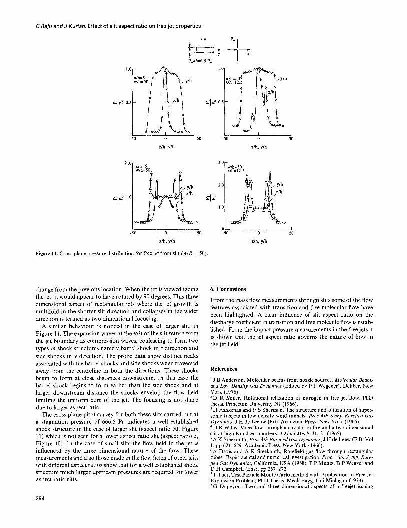
Figure 11. Cross plane pressure distribution for free jet from slit (A/R = 50).
change from the previous location. When the jet is viewed facing the jet, it would appear to have rotated by 90 degrees. This three dimensional aspect of rectangular jets where the jet growth is multifold in the shorter slit direction and collapses in the wider direction is termed as two dimensional focusing.
A similar behaviour is noticed in the case of larger slit, in
Figure 11. The expansion waves at the exit of the slit return from the jet boundary as compression waves, coalescing to form two types of shock structures namely barrel shock in z direction and side shocks in y direction. The probe data show distinct peaks associated with the barrel shocks and side shocks when traversed away from the centreline in both the directions. These shocks begin to form at close distances downstream. In this case the barrel shock begins to form earlier than the side shock and at larger downstream distance the shocks envelop the flow field limiting the uniform core of the jet, The focusing is not sharp due to larger aspect ratio.
The cross plane pitot survey for both these slits carried out at a stagnation pressure of 666.5 Pa indicates a well established shock structure in the case of larger slit (aspect ratio 50, Figure 11) which is not seen for a lower aspect ratio slit (aspect ratio 5, Figure 10). In the case of small slits the flow field in the jet is influenced by the three dimensional nature of the flow. These measurements and also those made in the Aow fields of other slits with different aspect ratios show that for a well established shock structure much larger upstream pressures are required for lower aspect ratio slits.
6. Conclusions
From the mass flow measurements through slits some of the flow features associated with transition and free molecular flow have been highlighted. A clear influence of slit aspect ratio on the discharge coefficient in transition and free molecule flow is estab-
lished. From the impact pressure measurements in the free jets it is shown that the jet aspect ratio governs the nature of flow in
the jet field.
’ J B Anderson, Molecular beams from nozzle sources. Molecular Beams and Low Den&y Gas Dynamics (Edited by P P Wegener). Dekker, New York (1976). *D R Miller, Rotational relaxation of nitrogen in free jet flow. PhD thesis, Princeton University NJ (1966). 3 H Ashkenas and F S Sherman, The structure and utilization of super- sonic freejets in low density wind tunnels. Proc 4th Symp RareJied Gas Dynamics, J H de Leeuw (Ed). Academic Press, New York (1966). 4 D R Willis, Mass Aow through a circular orifice and a two dimensional slit at high Knudsen numbers. J Fluid Mech, 21,21 (1965). ’ A K Sreekanth, Proc 4th Rarefied Gas Dynamics, J H de Leew (Ed), Vol 1, pp 621-629. Academic Press, New York (1966). 6A Davis and A K Sreekanth, Rarefield gas flow through rectangular tubes : Experimental and numerical investigation. Proc. 16th Symp. Rare- fied Gas Dynamics, California, USA (1988). E P Muntz, D P Weaver and D H Campbell (Eds), pp 257-272. ‘T Tuer, Test Particle Monte Carlo method with Application to Free Jet Expansion Problem, PhD Thesis, Mech Engg, Uni Michigan (1973). *G Dupeyrat, Two and three dimensional aspects of a freejet issuing
394

C Raju andJ Khan: Effect of slit aspect ratio on free jet properties
from a long rectangular slit. Proc 12th Symp Rarefied Gas Dynamics, Charlottesville, VA. S S Fisher (Ed), pp 1041048. AIAA Press, New York (1981). 9A E Beylich, Plane flow through an orifice. Proc 14th Symp Rarejied Gas Dynamics, H Ogucchi (Ed), pp 517-524. Uni Tokyo Press (1984). ‘OK Teshima Three dimensional characteristics of supersonic jets. Proc 17th Symp darefed Gus Dynamics, A E Beylich (Ed), pp 1042-1048 (1990). ” K Teshima, Structure of freejets from slit orifices. Proc 15th Symp
Rarejied Gas Dynamics, V Boffi and C Cercignani (Eds), pp 595-604. Grado, Italy (1986). ‘*C Raju, AK Sreekanth and Job Kurian, Impact pressure measurements in a high speed rarefield flow. Mechanics Research Communications, 21, 131 (1994). I3 A H Shapiro, The Dynamics and Thermodynamics of Compressible Fluid Flow, Vol 1, Chapter 15. The Ronald Press Company, New York (1953). 14A E Beylich, Struktur von uberschall-freistrahlen aus Schlitzblenden. Z Flugwiss, Weltraumforsch. 3, Heft 1, pp 48-58 (1979).
395


![[XLS]ncseducation.comncseducation.com/Result-on-Website.xls · Web viewMordijiush J. Sangma SLIT-2247 Akash Boro SLIT-2248 Anisha Das SLIT-2249 Udit Narayan Roy SLIT-2250 Michael](https://img.dokumen.tips/doc/110x75/5ab167d47f8b9a6b468c7b61/xls-viewmordijiush-j-sangma-slit-2247-akash-boro-slit-2248-anisha-das-slit-2249.jpg)