Embed Size (px)
Citation preview

simodrive
s
ECS Motor Spindle2SP1
Configuration Manual 03/2007 Edition


03/2007 Edition
SIMODRIVE
ECS Motor Spindle2SP1
Configuration Manual
Safety Information 1
FAQ 2
Function of the Spindle 3
Mechanical Data 4
Electrical Data 5
Supplying the Various Media 6
Sensors 7
Control 8
Order Number 9
Data Sheets 10
References A
Abbreviations andTerminology B
Index C

Designation of the documentation
Printing history
Brief details of this edition and previous editions are listed below.
The status of each edition is shown by the code in the ”Remarks” column.
Status code in the ”Remarks” column:
A New documentation. . . . .B Unrevised reprint with new Order No.. . . . .C Revised edition with new status. . . . .
Edition Order No. Remark02.03 6SN1 197-0AD04-0BP0 A10.04 6SN1 197-0AD04-0BP1 C11.05 6SN1 197-0AD04-0BP2 C03.07 6SN1 197-0AD04-0BP3 C
TrademarksSIMATICr, SIMATIC HMIr, SIMATIC NETr, SIROTECr, SINUMERIKr, SIMODRIVEr andMOTION-CONNECTr are registered trademarks of Siemens AG. Other names in this publication mightbe trademarks whose use by a third party for his own purposes may violate the rights of the registeredholder.
Additional information is available in the Internet at:http://www.siemens.com/motioncontrol
This publication was produced with Interleaf V 7
© Siemens AG 2007. All rights reserved.
The controller may support functions that are not described in thisdocumentation. However, no claim can be made regarding theavailability of these functions when the equipment is first supplied orin the event of servicing.
We have checked that the contents of this document correspond tothe hardware and software described. Since deviations cannot beprecluded entirely, we cannot guarantee complete conformance. Theinformation given in this publication is reviewed at regular intervalsand any corrections that might be necessary are made in thesubsequent printings. Suggestions for improvement are alsowelcome.
Subject to change without prior notice.
Siemens AktiengesellschaftOrder No. 6SN1 197--0AD04--0BP3Printed in the Federal Republic of Germany
3ls

v© Siemens AG 2007 All rights reserved2SP1 Motor Spindle (PMS), 03/2007 Edition, 6SN1197--0AD04--0BP3
Foreword
Information on the documentation
You will find an overview of the publications, which is updated on a monthly basis,in the available languages on the Internet under: http://www.siemens.com/motion-control.
Follow the menu items ”Support”→ ”Technical Documentation” → ”Overview ofDocuments”.
The Internet version of DOConCD (DOConWEB) is available at:
http://www.siemens.com/motioncontrol under menu option ”Support”.
Target group
Planners and project engineers
Benefits
The Configuration Manual supports you when selecting motors, calculating thedrive components, selecting the required accessories as well as when selectingline and motor--side power options.
Standard scope
The scope of the functionality described in this document can differ from the scopeof the functionality of the drive system that is actually supplied. Other functions notdescribed in this documentation might be able to be executed in the drive system.However, no claim can be made regarding the availability of these functions whenthe equipment is first supplied or in the event of servicing. The OEM documentsany supplements or changes that he makes.
For reasons of transparency, this documentation does not contain all detailed infor-mation about all types of the product and cannot cover every conceivable case ofinstallation, operation, or maintenance.

Foreword
vi© Siemens AG 2007 All rights reserved
2SP1 Motor Spindle (PMS), 03/2007 Edition, 6SN1197--0AD04--0BP3
Technical Support
Europe/Africa Asia/Australia America
Phone +49 (0) 180 5050-222 +86 1064 719 990 +1 423 262 2522
Fax +49 (0) 180 5050-223 +86 1064 747 474 +1 423 262 2289
Internet http://www.siemens.com/automation/support-request
E--mail mailto:[email protected]
Note
Country telephone numbers for technical support are provided under the followingInternet address: http://www.siemens.com/automation/service&support
Questions about the manual
If you have any questions (suggestions, corrections) regarding this documentation,please fax or e-mail us at:
Fax +49 9131 98 63315
E-Mail mailto:[email protected]
A fax form is available at the end of this document.
EC Declaration of Conformity
The EC Declaration of Conformity for the EMC Directive can be found/obtained inthe Internet: http://www.ad.siemens.de/csinfo
under the Product/Order No. 15257461 or at the relevant branch office of the A&DMC Division of Siemens AG.
Definition of qualified personnel
For the purpose of this documentation and warning information on the productitself, qualified personnel are those personnel who are familiar with the installation,mounting, start--up and operation of the equipment and the hazards involved.They must have the following qualifications:
S Trained and authorized to energize/de--energize, circuits and equipment inaccordance with established safety procedures.
S Trained in the proper care and use of protective equipment in accordance withestablished safety procedures.
S First aid training.

Foreword
vii© Siemens AG 2007 All rights reserved2SP1 Motor Spindle (PMS), 03/2007 Edition, 6SN1197--0AD04--0BP3
Explanation of symbols
The following danger and warning concept is used in this document:
!Danger
This symbol is always used if death, severe personal injury or substantial materialdamage will result if proper precautions are not taken.
!Warning
This symbol is always used if death, severe personal injury or substantial materialdamage can result if proper precautions are not taken.
!Caution
This symbol is always used if minor personal injury or material damage can resultif proper precautions are not taken.
Caution
The warning note (without a warning triangle) means that material damage canoccur if proper precautions are not taken.
Notice
This warning note indicates that an undesirable result or an undesirable status canoccur if the appropriate information is not observed.
Note
In this document, it can be advantageous to observe the information provided in aNote.

Foreword
viii© Siemens AG 2007 All rights reserved
2SP1 Motor Spindle (PMS), 03/2007 Edition, 6SN1197--0AD04--0BP3
Danger and warning information
!DangerS Start--up/commissioning is absolutely prohibited until it has been completely
ensured that the machine, in which the components described here are to beinstalled, is in full compliance with the specifications of Directive 98/37/EC.
S Only appropriately qualified personnel may commission the SIMODRIVE unitsand the motor spindles.
S This personnel must take into account the technical customer documentationbelonging to the product and be knowledgeable and observe the specifiedinformation and instructions on the hazards and warnings.
S Operational electrical units and motor spindles have parts, components andelectric circuits that are at hazardous voltage levels.
S When the machine or system is operated, hazardous axis movements canoccur.
S All of the work carried--out on the electrical machine or system must becarried--out with it in a no--voltage condition.
S SIMODRIVE drive units are designed for operation on low--ohmic, groundedline supplies (TN line supplies).
S SIMODRIVE units with motor spindles may only be connected to the linesupply through residual--current operated circuit--breakers, if corresponding toEN 50178, Chapter 5.2.11.2, it has been proven that the SIMODRIVE drive unitis compatible with the residual--current operated circuit--breaker.
!WarningS Perfect and safe operation of these units and motors assumes professional
transport, storage, mounting and installation as well as careful operator controland servicing.
S The information provided in Catalogs and quotations additionally applies tospecial versions of units and motors.
S In addition to the danger and warning information/instructions in the technicalcustomer documentation supplied, the applicable domestic, local andplant--specific regulations and requirements must be carefully taken intoaccount.
!CautionS It is not permissible that temperature--sensitive parts -- e.g. cables or electronic
components -- are in contact or mounted to the motor spindle.S When handling cables, please observe the following:
-- They may not be damaged,-- they may not be stressed,-- they cannot come into contact with rotating parts.

Foreword
ix© Siemens AG 2007 All rights reserved2SP1 Motor Spindle (PMS), 03/2007 Edition, 6SN1197--0AD04--0BP3
CautionS SIMODRIVE units with motor spindles are subject to a voltage test
corresponding to EN50178 as part of the routine test. While the electricalequipment of industrial machines is being subject to a voltage test incompliance with EN 60204-1, Section 19.4, all of the SIMODRIVE equipmentconnections must be disconnected/withdrawn in order to avoid damaging theSIMODRIVE equipment.
S It is not permissible to directly connect the motor spindles to the three--phaseline supply as this will destroy the motor spindles.
Notes
S SIMODRIVE equipment with motor spindles fulfill, in the operational state andin dry operating areas, the Low--Voltage Directive 73/23/EEC.
S SIMODRIVE equipment with motor spindles fulfill, in the configurations whichare specified in the associated EC Declaration of the Conformity, the EMCDirective 89/336/EEC.

Foreword
x© Siemens AG 2007 All rights reserved
2SP1 Motor Spindle (PMS), 03/2007 Edition, 6SN1197--0AD04--0BP3
Notes on ESDS
!Caution
ElectroStatic Discharge Sensitive Devices (ESDS) are individual components,integrated circuits, or modules that can be damaged by electrostatic fields ordischarges.
Handling regulations for ESDS:S When handling components, make sure that personnel, workplaces, and
packaging are well earthed.S Electronic components may only be touched by people in ESDS areas with
conductive flooring if-- These persons are grounded with an ESDS wrist band-- They are wearing ESDS shoes or ESDS shoe grounding strips.
S Electronic boards should only be touched if absolutely necessary.S Electronic boards must not come into contact with plastics or items of clothing
containing synthetic fibers.S Electronic modules must only be placed on conductive surfaces (table with
ESDS surface, conductive ESDS foam, ESDS packaging, ESDS transportcontainer).
S Electronic boards may not be brought close to data terminals,monitors or television sets. Minimum clearance to the screen > 10 cm.
S Measurements must only be taken on boards when:-- the measuring unit is grounded (e.g. via a protective conductor) or-- when floating measuring equipment is used, the probe is briefly discharged
before making measurements (e.g. a bare--metal control housing istouched).
Products from third--party manufacturers
The products from third--party manufacturers described in this document are prod-ucts which we know to be essentially suitable. It goes without saying that equiva-lent products from other manufacturers may be used. Our recommendation shouldonly be considered as such and not as a specification. We cannot accept any liabil-ity for the quality and properties/features of third--party products.
J

xi© Siemens AG 2007 All rights reserved2SP1 Motor Spindle (PMS), 03/2007 Edition, 6SN1197--0AD04--0BP3
Table of Contents
1 Safety Information 1-15. . . . . . . . . . . . . . . . . . . . . . . . . . . . . . . . . . . . . . . . . . . . . . . . . . . . .
1.1 Protection against potentially hazardous motion 1-15. . . . . . . . . . . . . . . . . . . .
1.2 Speed limits 1-18. . . . . . . . . . . . . . . . . . . . . . . . . . . . . . . . . . . . . . . . . . . . . . . . . . .
1.3 Responsibility for providing information to the companyoperating the machine 1-22. . . . . . . . . . . . . . . . . . . . . . . . . . . . . . . . . . . . . . . . . .
2 FAQ 2-23. . . . . . . . . . . . . . . . . . . . . . . . . . . . . . . . . . . . . . . . . . . . . . . . . . . . . . . . . . . . . . . . . .
2.1 What has to be observed after the equipment has been supplied? 2-23. . . .
2.2 How is a the shipment checked? 2-24. . . . . . . . . . . . . . . . . . . . . . . . . . . . . . . . .
2.3 How is the spindle unpacked? 2-25. . . . . . . . . . . . . . . . . . . . . . . . . . . . . . . . . . . .
2.4 How is the spindle laid--down vertically? 2-26. . . . . . . . . . . . . . . . . . . . . . . . . . .
2.5 How is the spindle installed/mounted? 2-27. . . . . . . . . . . . . . . . . . . . . . . . . . . . .
2.6 Which media should be connected after mounting/installation? 2-27. . . . . . .
2.7 Which electrical connections must be made after mounting/installation? 2-28
2.8 What has to be checked before the spindle is commissioned? 2-28. . . . . . . .
2.9 What has to be observed when starting to work with the spindle? 2-29. . . . .
3 Function of the Spindle 3-31. . . . . . . . . . . . . . . . . . . . . . . . . . . . . . . . . . . . . . . . . . . . . . . .
3.1 Overview of the functionality 3-32. . . . . . . . . . . . . . . . . . . . . . . . . . . . . . . . . . . . .
3.2 Drive motor 3-34. . . . . . . . . . . . . . . . . . . . . . . . . . . . . . . . . . . . . . . . . . . . . . . . . . . .
3.3 Cooling concept 3-35. . . . . . . . . . . . . . . . . . . . . . . . . . . . . . . . . . . . . . . . . . . . . . . .
3.4 Supply 3-36. . . . . . . . . . . . . . . . . . . . . . . . . . . . . . . . . . . . . . . . . . . . . . . . . . . . . . . .
4 Mechanical Data 4-39. . . . . . . . . . . . . . . . . . . . . . . . . . . . . . . . . . . . . . . . . . . . . . . . . . . . . . .
4.1 Observing the shutdown speed 4-39. . . . . . . . . . . . . . . . . . . . . . . . . . . . . . . . . . .
4.2 Installation conditions 4-39. . . . . . . . . . . . . . . . . . . . . . . . . . . . . . . . . . . . . . . . . . .4.2.1 Mechanical requirements placed on the spindle support 4-43. . . . . . . . . . . . .4.2.2 Support at the non--drive end 4-47. . . . . . . . . . . . . . . . . . . . . . . . . . . . . . . . . . . .
4.3 Spindle bearings 4-49. . . . . . . . . . . . . . . . . . . . . . . . . . . . . . . . . . . . . . . . . . . . . . .4.3.1 Features and operating conditions 4-49. . . . . . . . . . . . . . . . . . . . . . . . . . . . . . . .4.3.2 Warming--up phase of the motor spindle 4-50. . . . . . . . . . . . . . . . . . . . . . . . . . .4.3.3 Load capability of the spindle bearings 4-51. . . . . . . . . . . . . . . . . . . . . . . . . . . .4.3.4 Lifetime of the spindle bearings 4-52. . . . . . . . . . . . . . . . . . . . . . . . . . . . . . . . . .4.3.5 Maximum angular acceleration when the spindle is accelerating 4-54. . . . . .4.3.6 Stiffness 4-54. . . . . . . . . . . . . . . . . . . . . . . . . . . . . . . . . . . . . . . . . . . . . . . . . . . . . .4.3.7 Axial shaft growth 4-54. . . . . . . . . . . . . . . . . . . . . . . . . . . . . . . . . . . . . . . . . . . . . .
4.4 Tools and tool holders 4-56. . . . . . . . . . . . . . . . . . . . . . . . . . . . . . . . . . . . . . . . . . .4.4.1 Tools 4-56. . . . . . . . . . . . . . . . . . . . . . . . . . . . . . . . . . . . . . . . . . . . . . . . . . . . . . . . .4.4.2 Tool holders 4-59. . . . . . . . . . . . . . . . . . . . . . . . . . . . . . . . . . . . . . . . . . . . . . . . . . .
4.5 Clamping system and tool change 4-63. . . . . . . . . . . . . . . . . . . . . . . . . . . . . . . .4.5.1 Clamping system 4-63. . . . . . . . . . . . . . . . . . . . . . . . . . . . . . . . . . . . . . . . . . . . . . .4.5.2 Tool change 4-64. . . . . . . . . . . . . . . . . . . . . . . . . . . . . . . . . . . . . . . . . . . . . . . . . . .

Table of Contents
xii© Siemens AG 2007 All rights reserved
2SP1 Motor Spindle (PMS), 03/2007 Edition, 6SN1197--0AD04--0BP3
4.5.3 Tool changing for standard clamping systems 4-65. . . . . . . . . . . . . . . . . . . . . .4.5.4 Changing tools for the HSK A63 Type C tool holder 4-67. . . . . . . . . . . . . . . . .
4.6 Operating modes 4-70. . . . . . . . . . . . . . . . . . . . . . . . . . . . . . . . . . . . . . . . . . . . . . .
5 Electrical Data 5-71. . . . . . . . . . . . . . . . . . . . . . . . . . . . . . . . . . . . . . . . . . . . . . . . . . . . . . . . .
5.1 Definitions 5-71. . . . . . . . . . . . . . . . . . . . . . . . . . . . . . . . . . . . . . . . . . . . . . . . . . . . .
5.2 Motor 5-72. . . . . . . . . . . . . . . . . . . . . . . . . . . . . . . . . . . . . . . . . . . . . . . . . . . . . . . . .5.2.1 Advantages of a direct drive 5-72. . . . . . . . . . . . . . . . . . . . . . . . . . . . . . . . . . . . .5.2.2 Synchronous and induction motor versions 5-73. . . . . . . . . . . . . . . . . . . . . . . .5.2.3 General motor characteristics 5-74. . . . . . . . . . . . . . . . . . . . . . . . . . . . . . . . . . . .5.2.4 Suitable drive converter/system environment 5-76. . . . . . . . . . . . . . . . . . . . . . .5.2.5 Overvoltage protection (only for synchronous motors) 5-77. . . . . . . . . . . . . . .5.2.6 Star-delta mode (only for induction motors) 5-77. . . . . . . . . . . . . . . . . . . . . . . .5.2.7 System overview and engineering information/instructions 5-80. . . . . . . . . . .
5.3 Connecting cables/connector assignments 5-84. . . . . . . . . . . . . . . . . . . . . . . . .5.3.1 Power connection 5-84. . . . . . . . . . . . . . . . . . . . . . . . . . . . . . . . . . . . . . . . . . . . . .5.3.2 Direction of rotation 5-85. . . . . . . . . . . . . . . . . . . . . . . . . . . . . . . . . . . . . . . . . . . . .
6 Supplying the Various Media 6-87. . . . . . . . . . . . . . . . . . . . . . . . . . . . . . . . . . . . . . . . . . .
6.1 Overview, supplying the various media 6-87. . . . . . . . . . . . . . . . . . . . . . . . . . . .
6.2 Cooling medium 6-88. . . . . . . . . . . . . . . . . . . . . . . . . . . . . . . . . . . . . . . . . . . . . . . .6.2.1 Cooling water connections 6-89. . . . . . . . . . . . . . . . . . . . . . . . . . . . . . . . . . . . . . .6.2.2 Conditioning the cooling water 6-89. . . . . . . . . . . . . . . . . . . . . . . . . . . . . . . . . . .6.2.3 Cooling systems 6-91. . . . . . . . . . . . . . . . . . . . . . . . . . . . . . . . . . . . . . . . . . . . . . .
6.3 Compressed air 6-94. . . . . . . . . . . . . . . . . . . . . . . . . . . . . . . . . . . . . . . . . . . . . . . .6.3.1 Using compressed air 6-94. . . . . . . . . . . . . . . . . . . . . . . . . . . . . . . . . . . . . . . . . . .6.3.2 Compressed air connections 6-96. . . . . . . . . . . . . . . . . . . . . . . . . . . . . . . . . . . . .6.3.3 Conditioning the compressed air 6-97. . . . . . . . . . . . . . . . . . . . . . . . . . . . . . . . . .6.3.4 Hydraulic fluid flow data and controlling the hydraulic fluid flow
requirement 6-98. . . . . . . . . . . . . . . . . . . . . . . . . . . . . . . . . . . . . . . . . . . . . . . . . . .6.3.5 Standalone units to generate compressed air 6-99. . . . . . . . . . . . . . . . . . . . . .
6.4 Hydraulic (option, only for 2SP120) 6-100. . . . . . . . . . . . . . . . . . . . . . . . . . . . . . .6.4.1 Using hydraulics 6-100. . . . . . . . . . . . . . . . . . . . . . . . . . . . . . . . . . . . . . . . . . . . . . .6.4.2 Hydraulic connections 6-101. . . . . . . . . . . . . . . . . . . . . . . . . . . . . . . . . . . . . . . . . . .6.4.3 Hydraulic fluid flow data and controlling the hydraulic fluid flow
requirement 6-101. . . . . . . . . . . . . . . . . . . . . . . . . . . . . . . . . . . . . . . . . . . . . . . . . . .
6.5 Internal tool cooling using the cooling--lubricating medium (option) 6-102. . . .6.5.1 Operating conditions 6-104. . . . . . . . . . . . . . . . . . . . . . . . . . . . . . . . . . . . . . . . . . . .
6.6 External tool cooling with cooling--lubricating medium(option, only for 2SP120j) 6-106. . . . . . . . . . . . . . . . . . . . . . . . . . . . . . . . . . . . . . . .
6.6.1 Operating conditions 6-108. . . . . . . . . . . . . . . . . . . . . . . . . . . . . . . . . . . . . . . . . . . .
6.7 Media connections and coding 6-109. . . . . . . . . . . . . . . . . . . . . . . . . . . . . . . . . . .6.7.1 Media connections for 2SP120j 6-109. . . . . . . . . . . . . . . . . . . . . . . . . . . . . . . . . .6.7.2 Media connections for 2SP125j 6-115. . . . . . . . . . . . . . . . . . . . . . . . . . . . . . . . . .

Table of Contents
xiii© Siemens AG 2007 All rights reserved2SP1 Motor Spindle (PMS), 03/2007 Edition, 6SN1197--0AD04--0BP3
7 Sensors 7-119. . . . . . . . . . . . . . . . . . . . . . . . . . . . . . . . . . . . . . . . . . . . . . . . . . . . . . . . . . . . . . .
7.1 Encoder/angular encoder 7-119. . . . . . . . . . . . . . . . . . . . . . . . . . . . . . . . . . . . . . . .7.1.1 Electrical signals 7-119. . . . . . . . . . . . . . . . . . . . . . . . . . . . . . . . . . . . . . . . . . . . . . .7.1.2 Connecting the signal lines 7-123. . . . . . . . . . . . . . . . . . . . . . . . . . . . . . . . . . . . . .
7.2 Clamping state sensors 7-125. . . . . . . . . . . . . . . . . . . . . . . . . . . . . . . . . . . . . . . . .7.2.1 Analog and digital sensors of the 2SP120 spindle 7-125. . . . . . . . . . . . . . . . . . .7.2.2 Digital sensors of 2SP125 spindles 7-128. . . . . . . . . . . . . . . . . . . . . . . . . . . . . . .
7.3 Thermal sensors/motor protection 7-129. . . . . . . . . . . . . . . . . . . . . . . . . . . . . . . .
8 Control 8-133. . . . . . . . . . . . . . . . . . . . . . . . . . . . . . . . . . . . . . . . . . . . . . . . . . . . . . . . . . . . . . .
8.1 Conditions that enable the spindle to rotate 8-133. . . . . . . . . . . . . . . . . . . . . . . .
8.2 Clamping state sensors 8-134. . . . . . . . . . . . . . . . . . . . . . . . . . . . . . . . . . . . . . . . .8.2.1 Clamping state sensors 2SP120VV 8-134. . . . . . . . . . . . . . . . . . . . . . . . . . . . . . .8.2.2 Clamping state sensors 2SP125VV 8-140. . . . . . . . . . . . . . . . . . . . . . . . . . . . . . .
8.3 Tool change 8-143. . . . . . . . . . . . . . . . . . . . . . . . . . . . . . . . . . . . . . . . . . . . . . . . . . .8.3.1 Automatic tool change for 2SP120VV 8-143. . . . . . . . . . . . . . . . . . . . . . . . . . . . .8.3.2 Tool change sequence with standard clamping system and
tool change gripper 8-146. . . . . . . . . . . . . . . . . . . . . . . . . . . . . . . . . . . . . . . . . . . . .8.3.3 Tool change sequence with holding clamping system and
tool change gripper 8-147. . . . . . . . . . . . . . . . . . . . . . . . . . . . . . . . . . . . . . . . . . . . .8.3.4 Manual tool change for 2SP125VV 8-148. . . . . . . . . . . . . . . . . . . . . . . . . . . . . . .8.3.5 Automatic tool change for 2SP125VV 8-151. . . . . . . . . . . . . . . . . . . . . . . . . . . . .
9 Order Designation 9-155. . . . . . . . . . . . . . . . . . . . . . . . . . . . . . . . . . . . . . . . . . . . . . . . . . . . .
10 Data Sheets 10-159. . . . . . . . . . . . . . . . . . . . . . . . . . . . . . . . . . . . . . . . . . . . . . . . . . . . . . . . . . .
10.1 Technical characteristic data 10-159. . . . . . . . . . . . . . . . . . . . . . . . . . . . . . . . . . . . .
10.2 P/n and M/n diagrams 10-164. . . . . . . . . . . . . . . . . . . . . . . . . . . . . . . . . . . . . . . . . .10.2.1 2SP120V synchronous motor 10-164. . . . . . . . . . . . . . . . . . . . . . . . . . . . . . . . . . . .10.2.2 2SP125V synchronous motor 10-168. . . . . . . . . . . . . . . . . . . . . . . . . . . . . . . . . . . .10.2.3 2SP125V induction motor 10-172. . . . . . . . . . . . . . . . . . . . . . . . . . . . . . . . . . . . . . .
10.3 Dimension drawings 10-176. . . . . . . . . . . . . . . . . . . . . . . . . . . . . . . . . . . . . . . . . . . .
A References A-183. . . . . . . . . . . . . . . . . . . . . . . . . . . . . . . . . . . . . . . . . . . . . . . . . . . . . . . . . . . . .
B Abbreviations and Terminology B-187. . . . . . . . . . . . . . . . . . . . . . . . . . . . . . . . . . . . . . . . .
C Index C-189. . . . . . . . . . . . . . . . . . . . . . . . . . . . . . . . . . . . . . . . . . . . . . . . . . . . . . . . . . . . . . . . . .

Table of Contents
xiv© Siemens AG 2007 All rights reserved
2SP1 Motor Spindle (PMS), 03/2007 Edition, 6SN1197--0AD04--0BP3
Space for your notes

1-15© Siemens AG 2007 All rights reserved2SP1 Motor Spindle (PMS), 03/2007 Edition, 6SN1197--0AD04--0BP3
Safety Information
The specific issues relating to the functional safety of the motor spindle are ex-plained in this Chapter. These functional safety issues involve defining and moni-toring the spindle and tool--related speed limit values.
Table 1-1 Safety measures required
Measures to protect against
Electric shock Potentially hazardous motion
The spindle has the appropriate design.This means that there are no different mea-sures required than are otherwise appliedfor motors.
Measures are not specifically describedhere.
With reference to safe stopping, there areno different measures required than areotherwise applied for motors.
Specific for motor spindles:Functional safety by defining and monitor-ing the spindle and tool--related speedlimits.
1.1 Protection against potentially hazardous motion
In the following text, at several locations, reference will be made to theSINUMERIK Safety IntegratedR safety package. The requirements relating to ma-chine safety and the possibilities of using Safety IntegratedR for machine tools isdescribed in the associated Safety Integrated -- Application Manual, especially inChapters 1 and 5.
The 2SP1 motor spindle fulfills all of the relevant EU Directives. It is also possible,beyond this, to use the Safety IntegratedR option. These are certified according tothe EC--type examination test carried--out by a German regulatory body.
Depending on the operating mode (e.g. setting--up, production) of the machine,motor spindles, just like feed drives, represent a specific, potential hazard. Thismust be taken into account when designing and engineering the machine.
1

Safety Information
1.1 Protection against potentially hazardous motion
1-16© Siemens AG 2007 All rights reserved
2SP1 Motor Spindle (PMS), 03/2007 Edition, 6SN1197--0AD04--0BP3
Precautions
The protective goals of the EC Machinery Directive must be fulfilled by applyingsuitable protective measures. It is important that the machine is correctly used.
In order to implement these protective goals, in addition to being knowledgeableabout the applicable standards and Directives, it is also necessary to carefullyobserve the information and instructions in this Configuration Manual (refer toTable 1-2).
Table 1-2 Target group--specific documentation on the 2SP1 motor spindle
Target group Task of the target group Relevantdocumentation
Machine OEMs/designers
-- Carry--out a risk analysis
-- Draw--up a safety concept
-- Provide the necessary safetyequipment at the machine
-- Instruct the operating companyabout the ”correct use” of themachine and spindle
Configuration ManualandOperating Instructions
Company operating themachine
-- Inform/train employees aboutthe ”correct use” of the spindleand the application of the safetyfunctions and how they work
-- Reference to residual risks
Operating Instructions
When applied to the motor spindle, the potentially hazardous motion is when themaximum permissible speed for the spindle and/or tool is exceeded (refer to Figs.1-1 and 1-2).
Speed monitoring
Table 1-3 Possible strategies to monitor the speed
Degree of reliability of the speedmonitoring which is strived for
Features and requirements of thetechnology used
Standard Can be implemented (without additionaltechnology) using the existing operating andmachine technology
Safe Must be implemented in a safety--related fash-ion (e.g. through two channels).
Must correspond to the required control cate-gory (according to EN 954-1).
Must be authorized/certified for specific ma-chines.

Safety Information
1.1 Protection against potentially hazardous motion
1-17© Siemens AG 2007 All rights reserved2SP1 Motor Spindle (PMS), 03/2007 Edition, 6SN1197--0AD04--0BP3
When using a machine tool spindle, the machinery construction OEM is alwaysresponsible in taking the appropriate measures to detect and to avoid speeds thatare not permitted and their associated effects -- and to instruct the company usingthe machine about these measures.
When an inadmissible speed occurs, then the spindle must be stopped. In thiscase, the limit value is interpreted as that value where the maximum permissiblespeed is exceeded. This limit value depends on the following factors:
S Operating state (setting--up or automatic mode)
S Tool which is currently being used (refer to Fig. 1-1)
S Maximum permissible spindle speed (refer to Fig. 1-2)
Table 1-4 Measures to prevent the maximum speed being exceeded and its effects
Level of the measures Example of safety measures
Preventing the speedbeing exceeded
-- Monitoring the spindle speed
-- Activating tool--specific limit values
-- Monitoring operational and cutting parameters
-- Monitoring the tool condition
Controlling the effectwhen the speed is ex-ceeded
-- Providing machine panels which can withstand themaximum impact of pieces which are thrown off at themaximum energy which can be assumed
-- Ensure that these machine panels can only be openedat a defined low spindle speed
-- Automatic stopping when faults/errors occur
Future--oriented strategies which are applied to limit risks, distinguish themselvesby the fact that they are measures which are practical and safe and which are de-signed to avoid faults and errors. This means that the machinery construction com-pany has a certain degree of flexibility in appropriately reducing the costs involvedto control faults and errors.
Safety Integrated as a measure to avoid faults
Safety Integrated is an efficient measure which is optionally available at the faultprevention level. It can be used to monitor the drive functions.
The basic Safety IntegratedR principle is based on a two--channel monitoring func-tion. This means that the requirements from the EC Machinery Directive can besimply and cost--effectively fulfilled.
Example for Safety IntegratedR:The maximum energy of broken tool pieces, flung--out, can be safely limited usingSafety Integrated by activating the tool--specific limit value. This means that thecosts and resources which would otherwise be incurred for providing the appropri-ate machine panels with the corresponding strength, can be significantly reduced.

Safety Information
1.2 Speed limits
1-18© Siemens AG 2007 All rights reserved
2SP1 Motor Spindle (PMS), 03/2007 Edition, 6SN1197--0AD04--0BP3
Table 1-5 Excessive speed -- fault prevention using Safety Integrated®
Type of error Avoided by ...
Excessive spindle speed -- ”Safely reduced speed”
-- Safe spindle stopping when faults occur
Excessive tool speed (for toolswhose maximum speed lies be-low the maximum spindlespeed)
-- ”Safely reduced speed” as a function of the toolbeing used
-- The tool is detected in a safety--related fashionby ”safely reading” the tool coding, or
-- The tool is detected in a safety--related fashionby reading the tool coding and making a compa-rison with the program parameters
-- Safety--related stopping of the spindle
1.2 Speed limits
The spindle is designed for a maximum operating speed. This is specified as”maximum speed” in Chapter 10. The operating company can use this speed inoperation.
Maximum operating speed
The maximum operating speed is the highest speed that the spindle can be oper-ated at. This speed can be saved in the control and part programs.
Shutdown speed
The speed limit, where the system is shutdown if this value is exceeded, is desig-nated in this document as ”Shutdown speed”.
The machinery construction manufacturer (OEM) defines this taking into accountthe secondary conditions and limitations which apply to the spindle and tool. Theshutdown speed should be defined so that shutdown does not occur during normaloperation and, on the other hand, the spindle system and tool are not overloadeddue to speed peaks which are permitted. The spindle must be shutdown if erro-neous functions occur and the speed is exceeded. Standard technology or alsosafety--related technology can be used to monitor the speed (refer to Table 1-3).

Safety Information
1.2 Speed limits
1-19© Siemens AG 2007 All rights reserved2SP1 Motor Spindle (PMS), 03/2007 Edition, 6SN1197--0AD04--0BP3
Adapting the shutdown speed to various tools
If the maximum speed, which is permitted for the tool currently being used, liesbelow the maximum operating speed of the spindle, then the speed monitoring andthe shutdown speed must be adapted to the particular tool.
!Warning
The shutdown speed may only be set a maximum of 15% above the maximumoperating speed of the spindle.
The shutdown speed may not be set higher than the permitted maximum speed ofthe tool. The maximum operating speed, programmed for the tool, must be limitedto a value, which lies a minimum of 5% below the shutdown speed (refer to Fig.1-1).
n
[RPM]
Maximum programmablespindle speed
Spindle shutdown speed
Maximum programmablespeed of tool 2
Tool 2Tool 1 Tool 3
Tool 2
Tool 1
Tool 3
max. +15%
Shutdown speed of tool 2(= max. permissible speed of tool 2)
min. --5%
Maximum programmablespeed of tool 1 min. --5%
Shutdown speed of tool 1(= max. permissible speed of tool 1)
Fig. 1-1 Adapting the shutdown speed to various tools

Safety Information
1.2 Speed limits
1-20© Siemens AG 2007 All rights reserved
2SP1 Motor Spindle (PMS), 03/2007 Edition, 6SN1197--0AD04--0BP3
Table 1-6 Translation for Fig. 1-1
English German
RPM Umdrehungen pro Minute
Maximum programmable spindle speed Maximal programmierbare Drehzahl derSpindel
Maximum programmable speed of tool ... Maximal programmierbare Drehzahl desWerkzeugs ...
Tool 1, Tool 2, Tool 3 Werkzeug 1, Werkzeug 2, Werkzeug 3
Spindle shutdown speed Abschaltdrehzahl der Spindel
Shutdown speed of the tool Abschaltdrehzahl des Werkzeugs
Max. permissible speed of tool ... Maximal erlaubte Drehzahl für das Werk-zeug...
Caution
If various shutdown speeds are programmed for various tools, then this must beadapted to the tool using the Tool Manager. The machinery constructionmanufacturer (OEM) is responsible in clearly indicating to the operating companythat it is necessary to adapt the shutdown speed to the actual tool being used.
Critical speed
The critical speed is the speed where resonance vibration is excited in the com-plete mechanical structure.

Safety Information
1.2 Speed limits
1-21© Siemens AG 2007 All rights reserved2SP1 Motor Spindle (PMS), 03/2007 Edition, 6SN1197--0AD04--0BP3
Control--related speed peaks
The spindle speed is obtained as the result of a control (closed--loop) process. De-pending on the particular controller setting and the load condition, it oscillatesaround the programmed setpoint. When the spindle is operated, it is therefore nor-mal that the spindle shaft assumes speeds which briefly lie above the programmedoperating speed. However, even if mechanical critical speeds are even briefly ex-ceeded, this can result in excessive material stressing and in turn damage. Thismeans that tools and spindle systems must be able to withstand normal speedpeaks as a result of control operations.
n
t [ms]
[RPM]
Programmedspeed
Shutdown speed
Fig. 1-2 Control--related speed peaks
Table 1-7 Translation for Fig. 1-2
English German
RPM Umdrehungen pro Minute
Programmed speed maximale Betriebsdrehzahl
Shutdown speed Abschaltdrehzahl
In order to ensure the appropriate degree of safety at all permitted operationalspeeds, the speed peaks must be taken into account when designing the machine(e.g. the natural resonance of the spindle support) and when selecting the tools.
This is the reason that the subjects relating to natural resonance and centrifugalforce strength, discussed in Chapter 4, do not refer to the speed programmed fornormal operation, but always refer to the shutdown speed which is higher.

Safety Information
1.3 Responsibility for providing information to the company operating the machine
1-22© Siemens AG 2007 All rights reserved
2SP1 Motor Spindle (PMS), 03/2007 Edition, 6SN1197--0AD04--0BP3
1.3 Responsibility for providing information to the companyoperating the machine
Some of the information provided in this Configuration Manual must also be com-municated to the machinery construction company (OEM).
It is the clear responsibility of the machinery construction company (or the com-pany which markets the machine) to communicate the appropriate information andinstructions to the company actually operating the machinery. Refer to Table 1-8 fora summary.
Table 1-8 Overview: Important information for the company operating the machine
Subject Chapter
Instructing the company, operating the machine, about measures to detect and to avoidinadmissible speeds and their effects
1.1
Adapting the shutdown speed to the tool 1.2
In order to achieve the normal bearing lifetime, it is absolutely necessary that the air seal-ing system is correctly operated
4.3.1
The necessity to check the bearing load 4.3.3
Reference to possible damage when overloading the bearings 4.3.3
Information regarding the highest programmable angular acceleration = 4.3.5
Note that it is strictly forbidden to adjust the position of the clamping state sensors 4.5
Information on the the prerequisites which the tool must fulfill when used on an 2SP1motor spindle
4.4.1
Reference to the potential hazards and potential damage when using tools which are notsuitable
4.4.1
J
15000 RPM0.5 s

2-23© Siemens AG 2007 All rights reserved2SP1 Motor Spindle (PMS), 03/2007 Edition, 6SN1197--0AD04--0BP3
FAQ
2.1 What has to be observed after the equipment has beensupplied?
!Caution
Do not allow the crate with the spindle to fall.
Do not push--over the crate with spindle.
Always lay down the crate with spindle horizontally.
Only raise the crate using suitable equipment (fork--lift truck with the appropriatefork or crane).
The spindle may only be transported in the original crate.
While transporting the crate ensure that it is always in the horizontal position.
After the spindle has been supplied in the sealed packaging (wooden crate/foil),store it in a dry room with temperature control (10 to 35_ C).
The spindle must be kept sealed in the packing until it is mounted/installed in themachine.
A maximum of 3 crates may be stacked on top of one another.
Fig. 2-1 Transport crate in which the spindle is shipped
2

FAQ
2.2 How is a the shipment checked?
2-24© Siemens AG 2007 All rights reserved
2SP1 Motor Spindle (PMS), 03/2007 Edition, 6SN1197--0AD04--0BP3
2.2 How is a the shipment checked?
1. Place the crate with spindle in a horizontal position.
2. Remove the packaging straps using the appropriate shears.
3. Remove the crate cover (tools are not required).
4. Carefully open the foil.
5. Check that the contents are complete.
6. Check for damage during transport.
7. Re--package the spindle in the foil.
8. Close the crate using the cover and store (refer to Chapter 2.1).
Fig. 2-2 To check the shipment open the foil

FAQ
2.3 How is the spindle unpacked?
2-25© Siemens AG 2007 All rights reserved2SP1 Motor Spindle (PMS), 03/2007 Edition, 6SN1197--0AD04--0BP3
2.3 How is the spindle unpacked?
1. Screw the ring bolts (1) -- supplied with the spindle -- into the threads provided.
2. Attach the hoisting equipment to the ring bolts.
3. Lift the spindle from the crate in a horizontal position and place down onwooden blocks.
11
Fig. 2-3 Attaching the ring bolts (1)
Fig. 2-4 Locating the spindle on the wooden V--shaped blocks in a horizontal position
!Caution
Do not lift the spindle at the shaft (this will damage the bearings).

FAQ
2.4 How is the spindle laid--down vertically?
2-26© Siemens AG 2007 All rights reserved
2SP1 Motor Spindle (PMS), 03/2007 Edition, 6SN1197--0AD04--0BP3
2.4 How is the spindle laid--down vertically?1. Screw--in the 2 ring bolts into the bearing cover.2. Cover the spindle head with a protective jacket (for the spindle jacket design,
refer to Fig. 2-6.3. Attach the hoisting equipment to the ring bolts attached to the bearing flange
and carefully lift, refer to Fig. 2-5, Drawing A.4. Carefully bring the spindle unit into the vertical position above the protective
jacket, refer to Fig. 2-5, Drawing B. Secure the spindle so that it cannot slide.When bringing the spindle into the vertical position no force may be introducedinto the shaft.
5. Set--down the spindle unit with protective jacket in the vertical position, refer toFig. 2-5, Drawing C.
A B C
Fig. 2-5 Bringing the spindle into the vertical position
Fig. 2-6 Protective jacket

FAQ
2.5 How is the spindle installed/mounted?
2-27© Siemens AG 2007 All rights reserved2SP1 Motor Spindle (PMS), 03/2007 Edition, 6SN1197--0AD04--0BP3
2.5 How is the spindle installed/mounted?
1. Preparing the mounting location
-- The mounting location must be dry and dust--free
-- All of the required tools must be available
-- Only use suitable tools
2. Screw the ring bolts into the threads provided
3. Clean the spindle stock and apply a thin film of oil to the jointing surfaces
4. Horizontally/vertically install the spindle using the assembly equipment
Caution
Use guide rods to secure and support.
When mounting horizontally, also observe the alignment of the sealing air relief atthe bottom.
Neither stress nor crush the power cable.
Do not apply excessive force when jointing (this could damage the bearings).
Tighten the flange retaining bolts with a tightening torque of 125 Nm.
2.6 Which media should be connected after mounting/installation?
S The inlet/outlet hoses for the motor cooling should attached. The correct as-signment/inlet/outlet should be carefully observed. The supply pressures andflow rates must be checked against the specifications.
S The hose for the sealing air should be connected. Ensure that the supply pres-sure is correct.
S The hoses for ”release tool” and ”clamp tool” (hydraulic or pneumatic) should beconnected. The supply pressures and flow rates must be checked against thespecifications.
Notice
It is not permissible to close--off the ”clamp tool” bore. The transport plug must beremoved.
S The hose for the tool purge air should be connected. Ensure that the supplypressure is sufficient correspond to the specifications.
S The hose for the optional internal tool cooling should be connected. Carefullyobserve the max. pressure specifications, excessive pressure will result in damage.
FAQ
2.7 Which electrical connections must be made after mounting/installation?
2-28© Siemens AG 2007 All rights reserved
2SP1 Motor Spindle (PMS), 03/2007 Edition, 6SN1197--0AD04--0BP3
S The hose for the optional external tool cooling should be connected. Carefullyobserve the max. pressure specifications, excessive pressure will result indamage.
S For a detailed description, refer to section 6.
2.7 Which electrical connections must be made after mounting/installation?
S Electrical connections may not be made with the system under voltage(i.e. live).
S The power cables should be connected corresponding to the UVW coding (referto the electrical data).
S The signal cable for rotary encoder and motor temperature should be con-nected. The coding to align the connector should be carefully observed (refer tosensors). Joint connections must be easy to rotate.
S The signal cables to monitor the clamping status should be connected (carefullyobserve the assignment of the sensors). The coding to align the connectorshould be carefully observed (refer to sensors). Joint connections must be easyto rotate.
2.8 What has to be checked before the spindle is commissioned?
S Check that the shaft can be easily manually rotated. For synchronous spindles,the slot notching (permanent magnet rotor) must be able to be felt.
S The setting dimension of the tool interface should checked. Dimensions andsettings should be taken from the Operating Instructions.
S The tool draw--in force should be checked using the draw--in force measuringinstrument (e.g. OTT Power Check). Pull--in forces, refer to the Operating In-structions.
S The switching logic for ”clamp tool” and ”release tool” should be checked (referto the control). Checking the state ”clamped without tool”: Function check withthe tool removed. Check the function of the other clamping states using thepull--in force measuring unit (”0” setting value for OTT power check). Check the”draw bar in the release position” by manually releasing and check the functionat the sensor and the PLC.
S It should be checked as to whether the sealing air discharge is available at thesealing gap at the spindle nose.
S Using compressed air it should be checked that the rotary seal does not leakbefore the cooling--lubricating medium is connected/switched--on (check for airleakage at the tool interface; no air should leak at the leakage opening of therotary gland). The check must be made in the ”tool released” state.

FAQ
2.9 What has to be observed when starting to work with the spindle?
2-29© Siemens AG 2007 All rights reserved2SP1 Motor Spindle (PMS), 03/2007 Edition, 6SN1197--0AD04--0BP3
2.9 What has to be observed when starting to work with thespindle?
Start of work
Check the tool interface to ensure that it is clean and if required, clean.
Switch--in the supply media (air, water).
When commissioning for the first time and when starting the machine from cold,the running--in and warm operating regulations must be carefully observed, refer toChapter 4.3.2 or the Operating Instructions.
Notice
The spindle should already be in the warm operating state if the upper speedrange is approached.
Running--in the spindle after longer non--operational periods
See Chapter 4.3.2 or the Operating Instructions.
J

FAQ
2.9 What has to be observed when starting to work with the spindle?
2-30© Siemens AG 2007 All rights reserved
2SP1 Motor Spindle (PMS), 03/2007 Edition, 6SN1197--0AD04--0BP3
Space for your notes

3-31© Siemens AG 2007 All rights reserved2SP1 Motor Spindle (PMS), 03/2007 Edition, 6SN1197--0AD04--0BP3
Function of the Spindle
Applications
The 2SP1 motor spindle is a high--speed directly--driven tool spindle for milling anddrilling operations.
2SP1202
2SP1204
2SP1253
2SP1255
2SP1202
Fig. 3-1 2SP1 motor spindles
Features
The 2SP1 motor spindle is integrated into the SIMODRIVE drive system just likethe feed and main spindle motors.
The drive motor and the tool holder of the spindle form a mechanical unit whichhas a common bearing system. This eliminates all of the generally used mechani-cal transmission elements, such as belts or toothed couplings. With the directly--driven 2SP1 motor spindle, the user has many advantages over conventionalspindles with mechanical transmission elements. Further, directly--driven 2SP1motor spindles are very compact. The advantages include:
S High speeds because there are no mechanical transmission elements
S Smooth running properties as a result of the stable balancing arrangement
S Good speed stability, good closed--loop speed control
S High accuracy of the closed--loop position control
S Lower weight, more compact dimensions
S Lower mechanical design costs, as all of the functions are integrated
S Essentially compatible to the electrical drive system as the spindle, driveconverter and NC are engineered and supplied from a single source
3
Function of the Spindle
3.1 Overview of the functionality
3-32© Siemens AG 2007 All rights reserved
2SP1 Motor Spindle (PMS), 03/2007 Edition, 6SN1197--0AD04--0BP3
3.1 Overview of the functionality
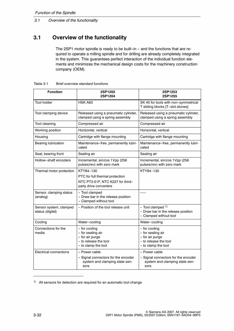
The 2SP1 motor spindle is ready to be built--in -- and the functions that are re-quired to operate a milling spindle and for drilling are already completely integratedin the system. This guarantees perfect interaction of the individual function ele-ments and minimizes the mechanical design costs for the machinery constructioncompany (OEM).
Table 3-1 Brief overview standard functions
Function 2SP12022SP1204
2SP12532SP1255
Tool holder HSK A63 SK 40 for tools with non--symmetricalT sliding blocks [T--slot stones]
Tool clamping device Released using a pneumatic cylinder,clamped using a spring assembly
Released using a pneumatic cylinder,clamped using a spring assembly
Tool cleaning Compressed air Compressed air
Working position Horizontal, vertical Horizontal, vertical
Housing Cartridge with flange mounting Cartridge with flange mounting
Bearing lubrication Maintenance--free, permanently lubri-cated
Maintenance--free, permanently lubri-cated
Seal, bearing front Sealing air Sealing air
Hollow--shaft encoders Incremental, sin/cos 1Vpp (256pulses/rev) with zero mark
Incremental, sin/cos 1Vpp (256pulses/rev) with zero mark
Thermal motor protection KTY84--130
PTC for full thermal protection
NTC PT3-51F, NTC K227 for third--party drive converters
KTY84--130
Sensor, clamping status(analog)
-- Tool clamped-- Draw bar in the release position-- Clamped without tool
------
Sensor system, clampedstatus (digital)
-- Position of the tool release unit -- Tool clamped 1)
-- Draw bar in the release position-- Clamped without tool
Cooling Water--cooling Water--cooling
Connections for themedia
-- for cooling-- for sealing air-- for air purge-- to release the tool-- to clamp the tool
-- for cooling-- for sealing air-- for air purge-- to release the tool-- to clamp the tool
Electrical connections -- Power cable
-- Signal connectors for the encodersystem and clamping state sen-sors
-- Power cable
-- Signal connectors for the encodersystem and clamping state sen-sors
1) All sensors for detection are required for an automatic tool change

Function of the Spindle
3.1 Overview of the functionality
3-33© Siemens AG 2007 All rights reserved2SP1 Motor Spindle (PMS), 03/2007 Edition, 6SN1197--0AD04--0BP3
Table 3-2 Brief overview of the possible options
Function 2SP12022SP1204
2SP12532SP1255
Tool cooling -- Inner tool cooling-- Ring for external tool cooling
-- Inner tool cooling
Max. speed 18,000 RPM 15,000 RPM (with HSK A63)
Thermal bearing monitor-ing
PT100 ------
Tool clamping device -- Released using a hydraulic cylinder-- Clamped using a spring assembly
------
Tool interface ------ BT 40, CAT 40, HSK A63

Function of the Spindle
3.2 Drive motor
3-34© Siemens AG 2007 All rights reserved
2SP1 Motor Spindle (PMS), 03/2007 Edition, 6SN1197--0AD04--0BP3
3.2 Drive motor
An integrated built--in motor drives the 2SP1 motor spindle. This built--in motor hasa high torque and its rotor is directly mounted onto the tool spindle. The electricpower is only fed to the stationary, outer section of the motor. The inner rotatingpart of the motor does not require any electric power.
These motor spindles are available in various speed classes. They are designedfor dynamic load operations and can quickly follow changing torque requirements.
Synchronous/induction motors
Depending on the frame size, the following motor versions are available.
S Motor spindle as synchronous motor
S Motor spindle as induction motor (option)
-- The induction (asynchronous) motor version is prepared so that the torquecan be adapted to the machining situation, for both the star and delta con-nection types. The operator can select the connection type as required (referto Chapter 4.2).
Designs
The motor spindle is available in 2 types of construction in order to graduated thepower demand:
S Short design
S Long design

Function of the Spindle
3.3 Cooling concept
3-35© Siemens AG 2007 All rights reserved2SP1 Motor Spindle (PMS), 03/2007 Edition, 6SN1197--0AD04--0BP3
3.3 Cooling concept
2SP1 motor spindles have integrated ducts to liquid--cool the stationary stator ofthe drive motor. The stator, which draws the electric drive power, represents themain source of power loss of the spindle unit. This is the reason that the coolingduct system is closely and thermally coupled to the drive motor stator. However,even sources of power loss (thermal energy) which are located further away aresufficiently cooled as a result of the integrated cooling ducts.
The spindle unit should be supplied with the cooling medium through a feed andreturn line. The cooling medium absorbs the power loss of the spindle whichmeans that the cooling medium temperature appropriately increases. The coolingmedium is cooled down to the original inlet temperature using an external coolingor heat--exchanger system mounted outside the spindle. This is the responsibilityof the machinery construction company. A pump must be used to provide the nec-essary cooling medium pressure in the inlet line. This external pump is also theresponsibility of the machinery construction company.
Refer to Chapter 6.2 for detailed basic data required to dimension and design thecooling medium supply.
Function of the Spindle
3.4 Supply
3-36© Siemens AG 2007 All rights reserved
2SP1 Motor Spindle (PMS), 03/2007 Edition, 6SN1197--0AD04--0BP3
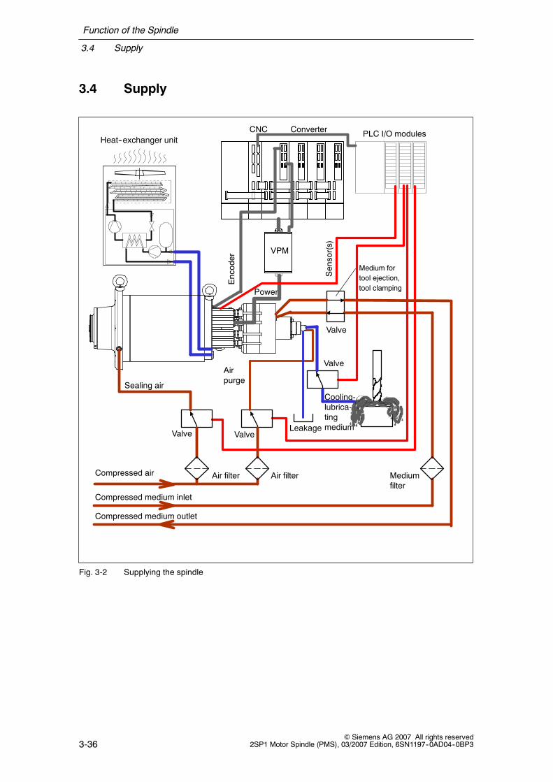
3.4 Supply
Compressed air Mediumfilter
Sealing air
Air filterAir filter
Valve Valve
Valve
Valve
Cooling-lubrica-tingmedium
VPM
Power
Sensor(s)
Encoder
Heat--exchanger unitCNC Converter PLC I/O modules
Medium fortool ejection,tool clamping
Airpurge
Leakage
Compressed medium inlet
Compressed medium outlet
Fig. 3-2 Supplying the spindle

Function of the Spindle
3.4 Supply
3-37© Siemens AG 2007 All rights reserved2SP1 Motor Spindle (PMS), 03/2007 Edition, 6SN1197--0AD04--0BP3
Table 3-3 Translation for Fig. 3-2
English German
Motor spindle Motorspindel
Compressed air Druckluft
Compressed medium inlet Druckmedium Zulauf
Compressed medium outlet Druckmedium Rücklauf
Valve Ventil
Air purge Kegelreinigungsluft
Air filter Luftfilter
Medium filter Mediumfilter
Sealing air Sperrluft
Medium for tool ejection, tool clamping Medium für Werkzeug lösen, Werkzeugspannen
Cooling-lubricating medium Kühlschmiermittel
Leakage Leckage
Heat-exchanger unit Wärmetauschersystem
Encoder Geber
Sensor(s) Sensor(en)
Electric power Elektrische Leistung
Converter Umrichter
PLC I/O unit PLC Ein-/Ausgabeeinheit
2SP1 motor spindles have integrated function elements to operate and control thevarious operations and sequences. The following media must be provided for thespindle, either through suitable cables or hoses:
S Electric power for the drive motor (the consumption depends on the powerdrawn)
S Cooling liquid (continuous flow; load depends on the power level)S Compressed air or hydraulic oil to actuate the tool clamping system -- de-
pending on the release unit type, either pneumatically or hydraulically operated(media only flows when releasing and clamping the tool)
S Air purge to clean the tool cone (this air is only used when releasing and eject-ing the tool)
S Sealing air to protect the bearings from dirt accumulating (this air is continuallyused)
S Optional cooling--lubricating medium supply for internal tool cooling (theflow depends on the actual process)
S Optional cooling--lubricating medium supply for external tool cooling (theflow depends on the actual process)
S 24 V electrical supply for the sensors to monitor the tool clamping state(power is continually drawn)
S Power supply for the rotary encoder (for SIEMENS drive converters, this isintegrated in the encoder interface)

Function of the Spindle
3.4 Supply
3-38© Siemens AG 2007 All rights reserved
2SP1 Motor Spindle (PMS), 03/2007 Edition, 6SN1197--0AD04--0BP3
The requirements regarding the conditioning of the various media, and which arerequired to design and dimension the various units and equipment, are describedin detail in Chapter 6 and Chapter 10.
J

4-39© Siemens AG 2007 All rights reserved2SP1 Motor Spindle (PMS), 03/2007 Edition, 6SN1197--0AD04--0BP3
Mechanical Data
The 2SP1 motor spindles allow operating companies to fully utilize the benefits ofhigh--speed machining. At high speeds, the components involved in the machiningoperation are subject to significant levels of stress. This means that the machinemust be mechanically designed to withstand the high speeds and the user mustharmonize and align the tools and the process conditions to the load capability ofthe spindle.
4.1 Observing the shutdown speed
Even if the critical speed is briefly exceeded, the following can occur:
S Vibration of the spindle carrier (support structure),
S the centrifugal strength of the tools can be exceeded,
and excessive mechanical stress can cause damage.
!Caution
The shutdown speed should be used as basis for load assumptions andstrength requirements. It is not permissible to use the speed which can beprogrammed for operation (refer to Chapter 1.2).
4.2 Installation conditions
The spindle is integrated into the machine assembly as a complete unit. The staticand especially the dynamic properties are obtained from the interaction betweenthe spindle itself and the spindle carrier of the machine.
4

Mechanical Data
4.2 Installation conditions
4-40© Siemens AG 2007 All rights reserved
2SP1 Motor Spindle (PMS), 03/2007 Edition, 6SN1197--0AD04--0BP3
Degree of protection
IP64 IP53
Drive end Non--drive end
Fig. 4-1 Degree of protection of the 2SP120 spindle
IP64 IP53
Drive end Non--drive end
Fig. 4-2 Degree of protection of the 2SP125 spindle
Table 4-1 Translation for Fig. 4-2
English German
Drive end A-Seite
Non-drive end B-Seite
Caution
The degree of protection refers to the ingress of water (DIN ISO EN 60034,Part 10). Cooling--lubricating mediums that contain oil, can creep and/or areaggressive, and can penetrate more than water.
Table 4-2 Degree of protection in front of and behind the mounting flange
In front of the mounting flange(drive end)
Behind the mounting flange(non-drive end)
Degree ofprotection
IP64 IP53
Description On the drive end, the spindle has a lab-yrinth seal and a connection for thesealing air. This therefore protects thespindle against the ingress of waterspray and dirt. It is not permissible thatcooling water acts directly on the laby-rinth seal. The specifications for thesealing air must be carefully observed,refer to Chapter 6.3.1.
The spindle support design must guaranteesuitable protection behind the mounting flangeagainst the effects from the machining area.
Mechanical Data
4.2 Installation conditions
4-41© Siemens AG 2007 All rights reserved2SP1 Motor Spindle (PMS), 03/2007 Edition, 6SN1197--0AD04--0BP3
Installing the spindle
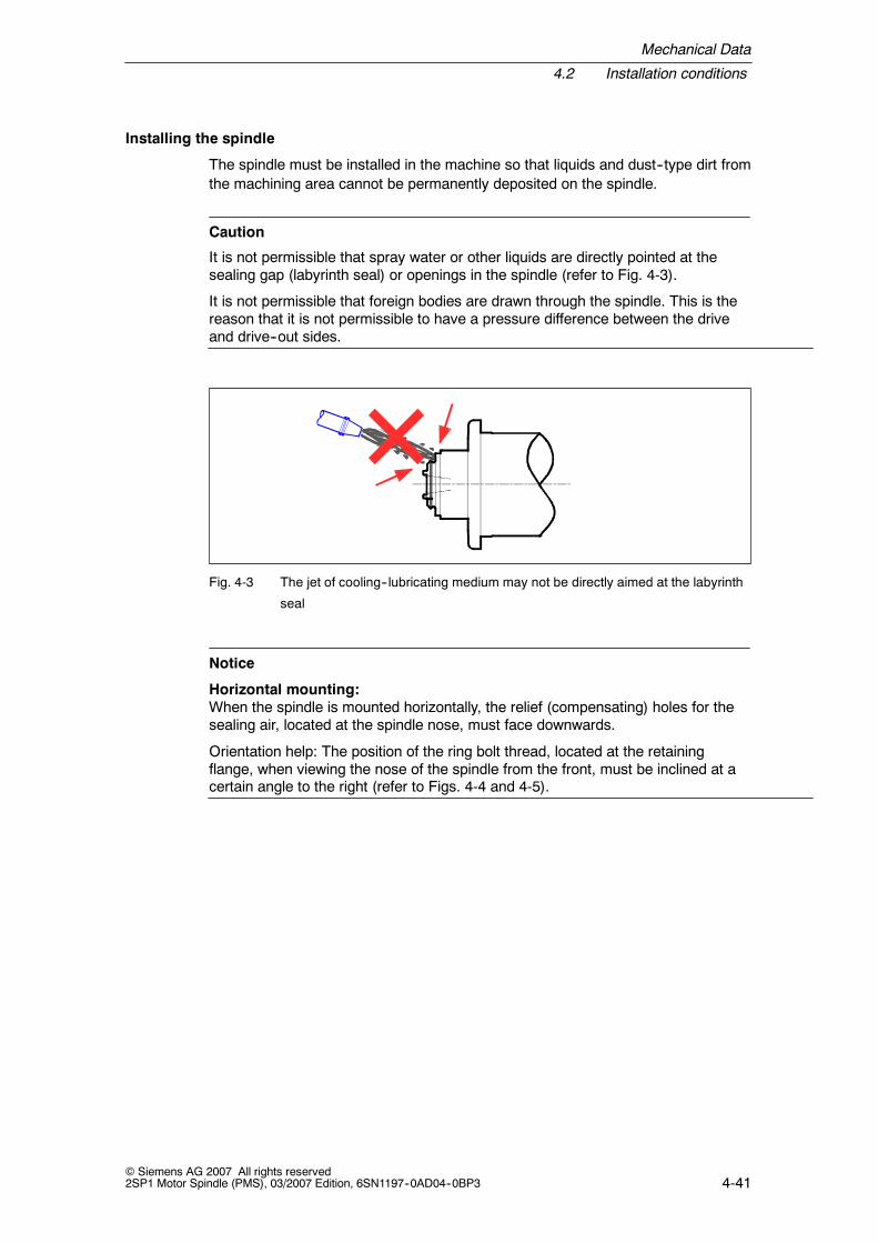
The spindle must be installed in the machine so that liquids and dust--type dirt fromthe machining area cannot be permanently deposited on the spindle.
Caution
It is not permissible that spray water or other liquids are directly pointed at thesealing gap (labyrinth seal) or openings in the spindle (refer to Fig. 4-3).
It is not permissible that foreign bodies are drawn through the spindle. This is thereason that it is not permissible to have a pressure difference between the driveand drive--out sides.
Fig. 4-3 The jet of cooling--lubricating medium may not be directly aimed at the labyrinth
seal
Notice
Horizontal mounting:When the spindle is mounted horizontally, the relief (compensating) holes for thesealing air, located at the spindle nose, must face downwards.
Orientation help: The position of the ring bolt thread, located at the retainingflange, when viewing the nose of the spindle from the front, must be inclined at acertain angle to the right (refer to Figs. 4-4 and 4-5).

Mechanical Data
4.2 Installation conditions
4-42© Siemens AG 2007 All rights reserved
2SP1 Motor Spindle (PMS), 03/2007 Edition, 6SN1197--0AD04--0BP3
M8 thread for ring bolt
Spindle below with horizontal mountingCompensatingholes for sealing air
Fig. 4-4 Mounting position of the 2SP120V spindle
M10 thread for ring bolt
Spindle below with horizontal mountingCompensatingholes for sealing air
Fig. 4-5 Mounting position of the 2SP125V spindle
Table 4-3 Translation for Figs. 4-4, 4-5
English German
M8/M10 thread for ring bolt Gewinde M8/M10 für Ringschraube
Spindle below with horizontal mounting Spindel unten bei horizontalem Einbau
Compensating holes for sealing air Entlastungsbohrungen für Sperrluft
The spindle must be mounted so that the motor spindle is not subject to any com-pulsive forces. If the housing is subject to tension, this can result in a slight de-formation and increased stressing on the roller bearings. This will have a negativeimpact on the smooth running characteristics, operating temperature and thereforethe lifetime.
Axial tapped holes (on the rear bearing cover) and radial tapped holes (on theflange and at the rear bearing cover) are provided on the spindle for lifting lugs.These are used when the spindle is mounted.

Mechanical Data
4.2 Installation conditions
4-43© Siemens AG 2007 All rights reserved2SP1 Motor Spindle (PMS), 03/2007 Edition, 6SN1197--0AD04--0BP3
4.2.1 Mechanical requirements placed on the spindle support
Load situation of the spindle support
The spindle is subject to an alternating force caused by the residual imbalance ofthe shaft and the tool. The residual imbalance transfers tilting and lateral forces tothe spindle mounting flange so that principally, the following associated vibrationtypes
S Tilting vibration (tilting from the non--drive end to the drive end)
S Lateral vibration (lateral movement of the spindle)
can be excited (refer to Fig. 4-6).
The forces excited by the residual imbalance increase with speed.
Drive end
Non--drive end
Lateralvibration
Deformation and displacement of spindle supportmake tilting and lateral vibration possible.
Fig. 4-6 Types of vibration which can be excited due to imbalance
Table 4-4 Translation for Fig. 4-6
English German
Non-drive end B-Seite
Drive end A-Seite
Tilting vibration Kippschwingung
Lateral vibration Seitwärtsschwingung
Deformation and displacement of spindlesupport make tilting and lateral vibrationpossible.
Verformung und unterschiedliche Plazier-ung des Spindelträgers ermöglichen Kipp-und Seitwärtsschwingungen.

Mechanical Data
4.2 Installation conditions
4-44© Siemens AG 2007 All rights reserved
2SP1 Motor Spindle (PMS), 03/2007 Edition, 6SN1197--0AD04--0BP3
The alternating stressing frequency precisely corresponds to the rotating frequencyof the spindle.
f = 1min/60s ⋅ N with f: exciting frequency in [Hz]N: speed in RPM
Vibrational characteristics: Mechanical design requirements placed on the spindle support
The spindle support must have a stiff design so that no natural resonance points ofthe appropriate vibration types can be generated over the complete speed rangeup to the shutdown speed. The lowest resonant frequency must lie abovethe rotating frequency of the shutdown speed which can be excited by animbalance condition. In this frequency range, the spindle support must be able toabsorb the tilting and lateral forces caused by the residual imbalance, withoutbeing deformed.
The spindle is mounted to the machine assembly at the drive end (front end) usingthe mounting flange. This must be taken into account in the mechanical design ofthe spindle support, especially when it comes to suppressing the tilting vibration ofthe rear (non--drive end) end of the spindle, which is relatively far away from themounting flange.

Mechanical Data
4.2 Installation conditions
4-45© Siemens AG 2007 All rights reserved2SP1 Motor Spindle (PMS), 03/2007 Edition, 6SN1197--0AD04--0BP3
Information regarding the design of the spindle support
The following points should be carefully observed when designing the spindle sup-port to accept the motor spindle:
S Material strengthThe fit area around the mounting flange is extremely important due to the highforce density to counteract the tilting vibration. The material thickness andstrength must be adequately dimensioned.
S Lateral stability of the flange planeThe plane of the mounting flange must be embedded so stiffly in the machinethat in the frequency range up to the shutdown speed, no vibrational types arepossible with lateral movement of the mounting flange. Designs, where theplane of the mounting flange is located far beyond the plane of the guide ele-ment of the spindle slide, are especially critical when it comes to a shift in theflange plane due to torsional rotation and deformation of the spindle support.
S Carefully observe the fit and toleranceThe spindle mounting flange must be attached to the spindle support so that itis geometrically precise and is as dynamically stiff as possible. The mechanicaldesign and the tolerances, which are documented in the drawings to accept themounting flange, must be carefully maintained. For drawings and dimensiondimension drawings, refer to Chapter 10. For the recommended tolerance forthe spindle support, refer to Fig. 4-7.
S Supporting the spindle support using the guide elementsThe guide elements (linear guides) which support the spindle support with re-spect to the machine bed, should provide an appropriately wide basis to with-stand tilting vibration (refer to Fig. 4-8).
S Short length between the spindle mounting flange and where the spindlesupport is retainedIf the spindle mounting flange extends in front of where the spindle support isretained, then this can undesirably reduce the resonant frequency of the tiltingvibration (refer to Fig. 4-8). This means that the length which extends betweenthe spindle mounting flange and the point where the spindle support is retainedat the machine bed should be kept as short as possible. This is also the reasonthat the spindle support should not have a high mass close to the flange planewhich does not directly serve to make the support assembly stiff.

Mechanical Data
4.2 Installation conditions
4-46© Siemens AG 2007 All rights reserved
2SP1 Motor Spindle (PMS), 03/2007 Edition, 6SN1197--0AD04--0BP3
Fig. 4-7 Mounting the spindle in the spindle support
attachmentSpindle support
Spindlesupport
Avoid massaccumulation ofspindle supportin this zone
Avoidlongunsupported
distances
Spindle mounting flange
Fig. 4-8 Example: Tilting vibration for an extended spindle mounting flange

Mechanical Data
4.2 Installation conditions
4-47© Siemens AG 2007 All rights reserved2SP1 Motor Spindle (PMS), 03/2007 Edition, 6SN1197--0AD04--0BP3
Table 4-5 Translation for Fig. 4-8
English German
Avoid long unsupported distances Größere frei tragende Längen vermeiden
Spindle support Spindelträger
Tilting vibration Kippschwingung
Spindle mounting flange Spindelbefestigungsflansch
Spindle support attachment Befestigung des Spindelträgers
Avoid mass accumulation of spindle supportin this area
Masseansammlung in diesem Bereich desSpindelträgers vermeiden
S Stiffening long unsupported lengthsLonger unsupported lengths should be avoided. If the spindle mounting flangeis extended, then appropriate ribs and transverse reinforcing elements shouldbe used. These reinforcing measures should be designed so that they counter-act tilting vibrations (refer to Fig. 4-6).
S No additional components mounted directly on the spindleIn order that the natural frequency of the tilting vibration is not undesirablyreduced, it is not permissible to mount or anchor any components directly onthe spindle. For example, connecting strain relief elements for drag cables.
Numerical techniques, such as the FEM--based modal analysis have proven them-selves to be helpful when evaluating a mechanical design regarding its vibrationalcharacteristics. For additional support, please contact your local Siemens office.
4.2.2 Support at the non--drive end
2SP1 motor spindles are available in several power classes. For the high--speedversions with high torques, an additional direct mechanical support is requiredbetween the non--drive end of the spindle and the spindle support.
For a list of the spindle types where the non--drive end support is specified, refer toChapter 10, Table 10-4 and 10-5.
Function of the support
The direct support between the non--drive end of the spindle and the spindlesupport has the function to stabilize the spindle against tilting vibrations so thatthe lowest resonance frequency lies above the rotational frequency of theshutdown speed.

Mechanical Data
4.2 Installation conditions
4-48© Siemens AG 2007 All rights reserved
2SP1 Motor Spindle (PMS), 03/2007 Edition, 6SN1197--0AD04--0BP3
Properties and characteristics of the support
This is the reason that the support design must be as stiff as possible to counterthe lateral vibration shown in Fig. 4-8. Further, this support must have a low massclose to the non--drive end. This is because an increase in the effective spindlemass at the non--drive end increases the moment of inertia of the tilting vibrationand in so doing undesirably lowers the resonant frequency. Also in this case,FEM--supported modal analysis can be effectively used when evaluating themechanical design.

Mechanical Data
4.3 Spindle bearings
4-49© Siemens AG 2007 All rights reserved2SP1 Motor Spindle (PMS), 03/2007 Edition, 6SN1197--0AD04--0BP3
4.3 Spindle bearings
High precision spindle bearings are used for the 2SP1 motor spindle shaft.They offer excellent precision and are designed to withstand loads at high speeds.Hybrid bearings are used for spindle versions which rotate at even higher speeds.
Special significance was placed on the ruggedness of the bearings. They haveproven themselves over many years in applications ranging from job shops up tothree--shift series production.
4.3.1 Features and operating conditions
The high precision spindle bearings absorb the radial and axis forces from the ma-chining process without any play. Thermal stressing of the spindle shaft does notinfluence the mechanical tension. The bearings have excellent balance quality andextremely low roughness.
Radial eccentricity (run--out) at the tool holder, refer to Chapter 10.
The spindle’s own sealing air system
The bearings are equipped with an integrated seal. The seal to the machiningspace at the spindle drive end is backed--up by the spindle’s own sealing airsystem, refer to Chapter 6.
Notice
In order to achieve the specified bearing lifetime, the sealing air system must becorrectly used. The machinery construction company is responsible in explainingthis to the company operating the spindle.
Bearing lubrication
2SP1 motor spindles have permanently lubricated bearings. This is the reason thatthey are maintenance--free. A re--lubrication device is not required.
Notice
The permanent grease lubrication may not be negatively influenced or polluted byother materials and substances.

Mechanical Data
4.3 Spindle bearings
4-50© Siemens AG 2007 All rights reserved
2SP1 Motor Spindle (PMS), 03/2007 Edition, 6SN1197--0AD04--0BP3
4.3.2 Warming--up phase of the motor spindle
Warming--up phase of the motor spindle (temperature distribution)
An uneven temperature distribution can have a negative impact on the bearing lifetime.
When commissioning for the first time and when starting the machine from cold,the running--in and warming--up specifications (refer to the the Operating Instruc-tions) must be carefully observed.
Notice
The spindle should already be in the warm operating state if the upper speedrange is approached.
Table 4-6 Warming--up phase of the motor spindle
Speed Operating time
25% of the maximum speed 2 min
50 % of the maximum speed 2 min
75 % of the maximum speed 2 min
Ready to operate
The machinery construction company can include a motor spindle warm--up cyclein the control software.
Longer periods of time where the spindle is not operational
Notice
A spindle must be run--in if it has not been used for more than one week.
Table 4-7 Running--in the spindle after longer non--operational periods
Speed Operating time
25% of the maximum speed 5 min
50 % of the maximum speed 5 min
75 % of the maximum speed 5 min
Ready to operate
Longer storage times
Notice
If the motor spindle has been stored for longer periods of time, the procedure forstoring spindles, described in the Operating Instructions, must be carefullyobserved.

Mechanical Data
4.3 Spindle bearings
4-51© Siemens AG 2007 All rights reserved2SP1 Motor Spindle (PMS), 03/2007 Edition, 6SN1197--0AD04--0BP3
4.3.3 Load capability of the spindle bearings
Bearing overload
Notice
High--speed bearings are sensitive to overload conditions.
This is the reason that in operation and at standstill, overload conditionsmust be avoided.
Table 4-8 Possible damage due to bearing overload and how it is avoided
Overload situation Damage Possibilities of avoiding the overloadsituation
Applying force whenassembling anddisassembling
Immediate bearingdamage
Machinery construction company and operatingcompany:
-- When assembling the spindle, it is not per-missible that forces are transferred to thespindle shaft and therefore to the bearings.The Operating Instructions must be carefullyobserved.
Machinery construction company:
-- Design the space in which the spindle is tobe mounted so that it can be easily acces-sed
-- Provide equipment for assembly and disas-sembly
-- Provide the operating company with the ap-propriate mounting/installation equipmentand resources
The effect of force due toa collision
The bearings areimmediately damagedorthe bearing lifetime is sig-nificantly reduced
Operating company:
-- Check new workpiece programs using aslow path velocity
-- Visualize the programmed tool paths on thecontrol side
Overload when a toolbreaks
The bearing lifetime isreduced
Operating company:
-- When a tool breaks, the spindle should bequickly brought to a standstill
The machinery construction company (OEM) is responsible in informing the oper-ating company about the possible damage if the spindle is overloaded.

Mechanical Data
4.3 Spindle bearings
4-52© Siemens AG 2007 All rights reserved
2SP1 Motor Spindle (PMS), 03/2007 Edition, 6SN1197--0AD04--0BP3
4.3.4 Lifetime of the spindle bearings
Grease lifetime
In many applications, the grease lifetime is, with respect to the fatigue lifetime, thedecisive factor which has to be taken into account therefore determining thespindle bearing lifetime The grease lifetime decreases with increasing speed (referto Fig. 4-9).
0
2000
4000
6000
8000
10000
2000
4000
6000
8000
10000
12000
14000
16000
n [RPM]
Greaselifetime[h]
18000
20000
12000
14000
16000
18000
20000
2SP1253--VHV0--0VV22SP1255--VHV0--0VV2
2SP1253--VHV0--1VV22SP1255--VHV0--1VV2
2SP1202--1HAVV--1DF22SP1204--1HAVV--1DF2
2SP1202--1HBVV--2DF22SP1204--1HBVV--2DF2
Fig. 4-9 Grease lifetime
A prerequisite for reaching the specified grease lifetime is that the permitted bear-ing temperatures are maintained.
The following must therefore be observed:
S The spindle cooling must be operated in compliance with the specifications
S It is not permissible that the bearing load is exceeded
S The maximum permissible ambient temperature in the operating state may notbe exceeded

Mechanical Data
4.3 Spindle bearings
4-53© Siemens AG 2007 All rights reserved2SP1 Motor Spindle (PMS), 03/2007 Edition, 6SN1197--0AD04--0BP3
Table 4-9 Determining the probable grease lifetime
Sequence Description, formulas
1. The spindle operation is sub--divided into constant speedphases
n
t operate[min]
[RPM] Repeat cycle t cycle
n1
t2 tk tK....
n2nK
n1
n2nK
t1
....
nk
....
....
2. The relative duration of thespeed phases is determined(relative proportion of the timein the cycle)
trel k =tktcycle
3. The individual grease lifetimeTuse k of the individual phasesis determined
n [RPM]
[h]
n1 nk nK n2
T life 2
T life k
T life k
Principle grease lifetime as afunction of the speed
Greaselifetime
Principle grease lifetime asa function of the speed
4. The individual lifetimes areadded in a weighted fashion toobtain the complete grease life-time
T use total=1
trel 1Tlife 1
trel 2Tlife 2
trel kTlife k
trel kTlife k
+ + ... + + ... +
Table 4-10 Translation for Fig. 4-9
English German
RPM Umdrehungen pro Minute
Repeat cycle Wiederholungszyklus
tcycle Zykluszeit
toperate Betriebsdauer
trel relative Zeitdauer einer Drehzahlphase
Grease lifetime Fettgebrauchsdauer
Tlife total Gebrauchsdauer gesamt
Tlife Gebrauchsdauer einer Phase

Mechanical Data
4.3 Spindle bearings
4-54© Siemens AG 2007 All rights reserved
2SP1 Motor Spindle (PMS), 03/2007 Edition, 6SN1197--0AD04--0BP3
4.3.5 Maximum angular acceleration when the spindle is accelerating
For extreme rates of angular acceleration and extremely short accelerating times,the rollers of the spindle bearings can slide rather than rotate. This has a negativeimpact on the bearing lifetime and must be avoided. When programming thespindle acceleration (and braking) it is imperative that a maximum angular accel-eration corresponding to 15000 RPM in 0.5 s is not exceeded.
N.≤ 15000 RPM
0.5 swith: N
.Programmed angular acceleration
The machinery construction company is responsible in clearly informing the oper-ating company that higher levels of angular acceleration may not be programmed.
4.3.6 Stiffness
The mechanical stiffness at the tool holder with respect to radial and axial forces isdocumented in the data sheets, Chapter 10. The natural bending of the tool addi-tionally shifts the cutting edge if radial forces are present. For narrow profile tools,the natural bending of the tool is significantly greater than the shift of the toolholder.
4.3.7 Axial shaft growth
The spindle shaft is subject to a geometrical shift in the axial direction. This shift isknown as shaft growth.
The shaft growth comprises the following elements:
S Thermally--related shaft growth
S Speed--related shaft growth
The shaft growth is independent of the tool being used.
Thermal shaft growth
In the thermal stabilization phase, while the spindle warms up, the spindle shafttemperature increases up to its steady--state condition. This means that during thisthermal stabilization phase, the tool holder shifts forwards (due to thermal expan-sion). After the warm--up phase has been completed, the spindle shaft essentiallyhas a constant operating temperature so that the tool holder no longer moves as aresult of thermal expansion.

Mechanical Data
4.3 Spindle bearings
4-55© Siemens AG 2007 All rights reserved2SP1 Motor Spindle (PMS), 03/2007 Edition, 6SN1197--0AD04--0BP3
Speed--related shaft growth
Due to the geometrical arrangement of the roller bearing assemblies, the rollingbearing contact point shifts in the bearing ring as a function of the speed. Thiscauses the tool holder to shift forwards. This shift is a function of the speed andincreases with increasing speed. This shift reverses as the speed decreases.
When required, this shaft growth can be equalized by correcting the Z axis. Werecommend that the thermally--related shaft growth and the speed--related shaftgrowth are determined by machining sample workpieces. The appropriate correc-tion tables can then be drawn--up for the Z axis position.

Mechanical Data
4.4 Tools and tool holders
4-56© Siemens AG 2007 All rights reserved
2SP1 Motor Spindle (PMS), 03/2007 Edition, 6SN1197--0AD04--0BP3
4.4 Tools and tool holders
4.4.1 Tools
The interaction between the motor spindle and the tools which are used has adecisive influence on the productivity and quality of the machining operation. Whenselecting the appropriate tools, the safety information and instructions relating tohigh speeds must be carefully observed.
As a result of the high speed, 2SP1 motors spindles allow excellent surface quali-ties and high productivity to be achieved. However, when incorrectly used, the highspeeds can also represent potential risks and significant wear. It is especially im-portant that the tools are carefully selected.
Only use tools which are in a perfect condition
The following behavior/characteristics in operation are only achieved when tools,which must be in a perfect condition, are correctly used:
S Perfect machining results
S Low vibration levels
S Low wear of the spindle bearings
S Low noise emission
S Safety of operating personnel and the machine
This is the reason that it must always be ensured that only tools in a perfect condi-tion are in the tool magazine -- and that these tools were checked to ensure thatthey are suitable for operation with the particular spindle. The machinery construc-tion company is responsible in clearly informing the operating company the poten-tial danger and damage if unsuitable tools were to be used.
Prerequisites for tools
The tools must fulfill the following prerequisites:
1. The tool must be released/certified for high speeds and centrifugal forces.
2. It is not permissible that the tool reduces the natural frequency of the spindleunit to below the critical rotating frequency.
3. The cutting forces and the intrinsic weight of the tool may not overload thebearings.
4. Ratio between the length and diameter, not greater than 3:1.
5. The tool must be perfectly balanced.
For a detailed description, of the specified prerequisites, refer to Table 4-11.
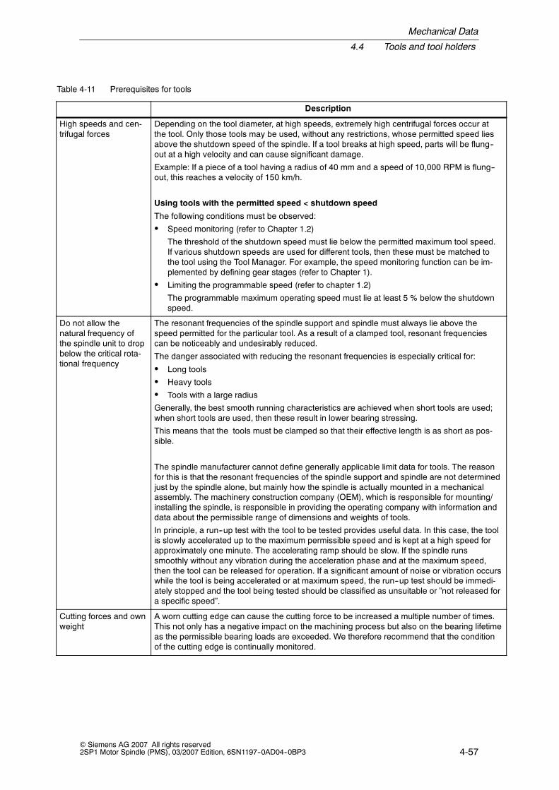
Mechanical Data
4.4 Tools and tool holders
4-57© Siemens AG 2007 All rights reserved2SP1 Motor Spindle (PMS), 03/2007 Edition, 6SN1197--0AD04--0BP3
Table 4-11 Prerequisites for tools
Description
High speeds and cen-trifugal forces
Depending on the tool diameter, at high speeds, extremely high centrifugal forces occur atthe tool. Only those tools may be used, without any restrictions, whose permitted speed liesabove the shutdown speed of the spindle. If a tool breaks at high speed, parts will be flung--out at a high velocity and can cause significant damage.
Example: If a piece of a tool having a radius of 40 mm and a speed of 10,000 RPM is flung--out, this reaches a velocity of 150 km/h.
Using tools with the permitted speed < shutdown speed
The following conditions must be observed:
S Speed monitoring (refer to Chapter 1.2)
The threshold of the shutdown speed must lie below the permitted maximum tool speed.If various shutdown speeds are used for different tools, then these must be matched tothe tool using the Tool Manager. For example, the speed monitoring function can be im-plemented by defining gear stages (refer to Chapter 1).
S Limiting the programmable speed (refer to chapter 1.2)
The programmable maximum operating speed must lie at least 5 % below the shutdownspeed.
Do not allow thenatural frequency ofthe spindle unit to dropbelow the critical rota-tional frequency
The resonant frequencies of the spindle support and spindle must always lie above thespeed permitted for the particular tool. As a result of a clamped tool, resonant frequenciescan be noticeably and undesirably reduced.
The danger associated with reducing the resonant frequencies is especially critical for:
S Long tools
S Heavy tools
S Tools with a large radius
Generally, the best smooth running characteristics are achieved when short tools are used;when short tools are used, then these result in lower bearing stressing.
This means that the tools must be clamped so that their effective length is as short as pos-sible.
The spindle manufacturer cannot define generally applicable limit data for tools. The reasonfor this is that the resonant frequencies of the spindle support and spindle are not determinedjust by the spindle alone, but mainly how the spindle is actually mounted in a mechanicalassembly. The machinery construction company (OEM), which is responsible for mounting/installing the spindle, is responsible in providing the operating company with information anddata about the permissible range of dimensions and weights of tools.
In principle, a run--up test with the tool to be tested provides useful data. In this case, the toolis slowly accelerated up to the maximum permissible speed and is kept at a high speed forapproximately one minute. The accelerating ramp should be slow. If the spindle runssmoothly without any vibration during the acceleration phase and at the maximum speed,then the tool can be released for operation. If a significant amount of noise or vibration occurswhile the tool is being accelerated or at maximum speed, the run--up test should be immedi-ately stopped and the tool being tested should be classified as unsuitable or ”not released fora specific speed”.
Cutting forces and ownweight
A worn cutting edge can cause the cutting force to be increased a multiple number of times.This not only has a negative impact on the machining process but also on the bearing lifetimeas the permissible bearing loads are exceeded. We therefore recommend that the conditionof the cutting edge is continually monitored.

Mechanical Data
4.4 Tools and tool holders
4-58© Siemens AG 2007 All rights reserved
2SP1 Motor Spindle (PMS), 03/2007 Edition, 6SN1197--0AD04--0BP3
Table 4-11 Prerequisites for tools, continued
Description
Ratio between thelength and diameter
Tools should be used whose ratio between L and diameter ∅ does not exceed a value of 3:1and whose total weight of the tool insert lies below 4.5 kg.
The spindles are designed so that with these tools, the critical speeds lie above themaximum spindle speed.
If tools are used whose dimensions deviate from this data, then the speed should becalculated. In addition to limiting the speed as a result of critical speeds of the spindle/toolsystem, speed limiting using technological data of the cutting process should be carefullytaken into consideration.
Tool holderTool employment
∅
L
L
∅3<
Balancing Only the most finely--balanced tools in compliance with Q 6.3 may be used.
Standards to be carefully observed and fulfilled:
S VDI Directive 2056
S DIN EN ISO 15641
Notice
Balancing must be made after the tool insert has been inserted in the tool holder. It isnot permissible to individually balance the tool insert and tool holder without balanc-ing the whole assembly.
A worn tool can have a noticeable negative impact on the balance quality. If vibration andnoise levels increase while a tool is being used, then the tool must be checked for wear andthe balance must also be re--checked.

Mechanical Data
4.4 Tools and tool holders
4-59© Siemens AG 2007 All rights reserved2SP1 Motor Spindle (PMS), 03/2007 Edition, 6SN1197--0AD04--0BP3
4.4.2 Tool holders
2SP1 motor spindles are available with several tool holders.
Table 4-12 Tool holders
Type Standard for speed Remark
SK 40 -- non--symmetrical DIN 69872, ISO 7388/1/2 Type A ≤ 10000 RPM 2SP125
CAT40 -- non--symmetrical ANSI B5.50-78, ISO 7388/1/2Type B
≤ 10000 RPM 2SP125
BT 40 -- non--symmetricalBT 40, 30_
MAS 403-1982, BT/PT30_Version E1
≤ 10000 RPM 2SP125
BT 40 -- non--symmetricalBT 40, 45_
MAS 403-1982 BT/PT45_Version F1
≤ 10000 RPM 2SP125
HSK A63 DIN 69893-1, ISO 12164-1 ≤ 18000 RPM≤ 15000 RPM
2SP1202SP125
Drawings, dimension tables and tolerance data, refer to Chapter10.
AA
A
B¦0.25
C¦0.25
DIN 69871 ISO/DIS 7388/1
0.02
DIN 69872 ISO/DIS 7388/2 Type A SK 40 44.45 94.25 88.25
A
¦ 0.25
B C
¦ 0.25
Fig. 4-10 SK 40

Mechanical Data
4.4 Tools and tool holders
4-60© Siemens AG 2007 All rights reserved
2SP1 Motor Spindle (PMS), 03/2007 Edition, 6SN1197--0AD04--0BP3
SK 40 44.45 84.50 79.25AA
A
J¦0.3
K
0.05
A
¦ 0.3
J K
¦ 0.3
Fig. 4-11 CAT 40
AA
A
E¦0.25
F¦0.25
MAS 403--1982 PT
0.02
MAS 403--1982 PT--2
30 °
BT/PT 30_ 44.45 100.35 93.35
A
¦ 0.25
E F
¦ 0.25
Fig. 4-12 BT 40, 30°

Mechanical Data
4.4 Tools and tool holders
4-61© Siemens AG 2007 All rights reserved2SP1 Motor Spindle (PMS), 03/2007 Edition, 6SN1197--0AD04--0BP3
AA
AE¦0.25
F¦0.25
MAS 403--1982 BT
0.02
MAS 403--1982 PT--1
45 °
BT/PT 45_ 44.45 100.35 93.35
A
¦ 0.25
E F
¦ 0.25
Fig. 4-13 BT 40, 45_
l1
f3
f1
l12
d2
d1 d9
h3b1
9 +0.090
HSK A63 12.54
b1
63 5348.01 26 18 5 32 21
d1 d2 d9 f1 f3 h3 l1 l12
h10¦ 0.04 0/--01 ¦ 0.1 +0.2/0 0/--0.2
Fig. 4-14 HSK A63

Mechanical Data
4.4 Tools and tool holders
4-62© Siemens AG 2007 All rights reserved
2SP1 Motor Spindle (PMS), 03/2007 Edition, 6SN1197--0AD04--0BP3
Tool changer
A tool is changed depending on the machine tool using either a gripper or by di-rectly gripping and placing the tool into a tool magazine.
Caution
In order to reliably prevent the spindle colliding with adjacent tools in the toolmagazine or in the tool gripper, depending on the particular spindle, certainminimum clearances should be maintained (refer to Table 4-13 and Fig. 4-15).
Table 4-13 Minimum clearances for various tool holders
Motor spindle Tool holder Minimum clearance [mm]
2SP120VV--1HVVV--VDF2 HSK A63 A ² 100.0
2SP125VV--VHV0V--1DV2 HSK A63 A ² 100.0
2SP125VV--VHV0V--0VV2 SK40 A ² 100.0
HSK A63SK 40
A
A
Fig. 4-15 Minimum clearance = dimension A

Mechanical Data
4.5 Clamping system and tool change
4-63© Siemens AG 2007 All rights reserved2SP1 Motor Spindle (PMS), 03/2007 Edition, 6SN1197--0AD04--0BP3
4.5 Clamping system and tool change
4.5.1 Clamping system
2SP1 motor spindles are equipped with a clamping system for automatic toolchanging. This clamping system is integrated in the spindle shaft and rotates withthe spindle.
The clamping system is designed for max. 5 tool change cycles per minute.
The pull--in force is provided by the spring system which rotates with the spindle.The tool is safely and reliably maintained in the clamped position even when thepower fails and while the spindle is rotating. The magnitude of the pull--in force isdescribed in Chapter 10.1.
Clamping state sensors
The spindle is equipped with sensors to monitor the clamping state. The variousclamped states are detected by sensing the axial position of the clamping or actua-tion system.
Table 4-14 Sensors to monitor the clamped state2SP1 20
Sensor Message Type Remark
S1 Dependent on the measured voltage Analog sensor Basic equipment
S4 Position of the release cylinder NO contact Basic equipment
Table 4-15 Sensors to monitor the clamped state2SP1 25
Sensor Message Type Remark
S1 Draw bar in the release position NO contact Basic equipment
S2 Tool is clamped NO contact Basic equipment
S3 Collet is closed without a tool inserted NO contact Basic equipment
Electrical data of the sensors, refer to Chapter 7.2.Evaluation of the sensors to control the tool change, refer to Chapter 8.
!Warning
The mounting position of the clamped state sensors is carefully adjusted in thefactory. It is not necessary for end users to move the position of the sensors and itis also strictly forbidden. The machinery construction company is responsible ininforming the operating company that it is not permissible to adjust the position ofthe sensors.

Mechanical Data
4.5 Clamping system and tool change
4-64© Siemens AG 2007 All rights reserved
2SP1 Motor Spindle (PMS), 03/2007 Edition, 6SN1197--0AD04--0BP3
4.5.2 Tool change
!Caution
It is only permissible to insert and release the tool when the motor spindle is at astandstill (zero speed). The tool must be inserted up to the contact surface of theclamping taper.
The clamping system is either actuated pneumatically or hydraulically using apneumatic or hydraulic cylinder.
Note
The air line between the compressed air source and the pneumatic/hydrauliccylinder must have an adequate cross--section in order to keep the times toestablish pressure and reduce pressure of the pneumatic/hydraulic cylinder short.
Recommended cross--section for the air line to the pneumatic cylinder: 8 mm.
Recommended cross--section for the oil line to the hydraulic cylinder: 5 mm.
For longer compressed air lines using drag chains we recommend that theflow--related pressure loss and the associated time to establish pressure in thecylinder is theoretically estimated.
The details and the waiting times to be maintained, the control of the mechanicalsequences of the clamping and release operations are described in Chapter 8.2.
The operating and flow rate data of the pneumatic/hydraulic cylinder are describedin Chapter 6.3 and 6.4.
Values for clamping and release pressures refer to Table 10-2.

Mechanical Data
4.5 Clamping system and tool change
4-65© Siemens AG 2007 All rights reserved2SP1 Motor Spindle (PMS), 03/2007 Edition, 6SN1197--0AD04--0BP3
4.5.3 Tool changing for standard clamping systems
Releasing tool
Pressure is applied to the cylinder to release the tool. The actuation device re-leases the tool from the tool holder so that it can be removed by the tool changinggripper without any force being required.
Sensor S1 is adjusted so that for tools in compliance with the standard it suppliesthe ”draw bar in the release position” signal.
When removing the tool, the appropriate control diagram must be taken into account:
Fig. 8-4: Automatic tool change (with S1 and S4) for 2SP120jFig.8-5: Manual tool change (with S2) for 2SP125jFig. 8-6: Automatic tool change (withS1, S2 and S3) for 2SP125j
!Caution
The released tool is only loosely located in the tool holder. It must be removedafter it has been released. If it is not removed, then it can simply fall out and causedamage.
Jammed tools cannot be reliably detected using sensor S1.
Inserting and clamping the tool
The tool is drawn--in and clamped just using disk springs.
For this operation, for spindles with pneumatic cylinder, the air in the cylinder mustfirst be released. In order to shorten the tool change times, compressed air can beadditionally applied to the rear of the piston.
For spindles with hydraulic cylinder, the piston side must be relieved (the pressurereduced) using an appropriate valve -- and pressure (hydraulic pressure) applied tothe rear of the piston.
For 2SP120V, the voltage of analog sensor S1 is measured to determine that thetool has been correctly clamped.
For 2SP125V, digital sensor S2 indicates whether the tool has been correctlyclamped.
While inserting a tool, the release pressure must be switched through to the pneu-matic or hydraulic cylinder until sensor S1 signals that the clamping system isready for tool insertion. The tool can only be inserted after this signal is present.

Mechanical Data
4.5 Clamping system and tool change
4-66© Siemens AG 2007 All rights reserved
2SP1 Motor Spindle (PMS), 03/2007 Edition, 6SN1197--0AD04--0BP3
!Caution
The gripper must completely introduce the tool into the tool holder. It must preventthe tool from either sliding or dropping--out until the clamped state has beenachieved (e.g. an appropriate signal from sensor S1 for 2SP120V motor spindlesor from sensor S2 for 2SP125V until a specific voltage level has been achieved).
!Caution
The spindle may only rotate if the cylinder piston has withdrawn from the spindleshaft and has not contact with it. This means that it is not permissible that arelease pressure is applied to the pneumatic or hydraulic cylinder!
When the release pressure is applied to the cylinder, the stationary cylinder pistonmakes contact with the rotating clamping system of the spindle shaft. If it would bein contact while the spindle is rotating, this would damage the clamping system.This is the reason that spindle rotation may only be enabled if there is no releasepressure and the sensor system clearly indicates that a tool has been safely andreliably clamped. While the spindle is rotating, the pressure feed to release the toolmust be safely and securely shut--off.
!Caution
The spindle may not rotate if it does not have a clamped tool!If a clamping operation is carried--out without a tool being ready at the front forinsertion, then the collet and draw bar retract to behind their normal clampingposition. This status is permitted -- however, it is not permissible that the spindlerotates at a high speed. Only slow spindle speeds of below 100 RPM arepermissible to position the spindle.

Mechanical Data
4.5 Clamping system and tool change
4-67© Siemens AG 2007 All rights reserved2SP1 Motor Spindle (PMS), 03/2007 Edition, 6SN1197--0AD04--0BP3
4.5.4 Changing tools for the HSK A63 Type C tool holder
Releasing tool
Pressure is applied to the cylinder to release the tool. The actuation mechanismreleases the tool from the tool holder.
Sensor S1 is adjusted so that for tools in compliance with the standard it suppliesthe ”draw bar in the release position” signal.
When removing the tool, the appropriate control diagram must be taken into account:
See Fig. 8-4: Automatic tool change (with S1 and S4) for 2SP120j
For a holding clamping system, the tool is still held with a defined holding force inthe tool holder using springs. A tool can only be removed after first overcoming theholding force. To do this, force must be applied by the tool changer.
Inserting and clamping the tool
While inserting a tool, the release pressure must be switched through to the pneu-matic or hydraulic cylinder until sensor S1 signals that the clamping system isready for tool insertion. The tool can only be inserted after this signal is present.
For a holding clamping system, when the tool is inserted, it is initially only held inthe tool holder by the holding function of the springs without the tool being clampedin the tool holder. The tool change gripper no longer has to hold the tool after it hasbeen inserted as this function is handled by the holding clamping system.
The tool is drawn--in and clamped just using disk springs.
For this operation, for spindles with pneumatic cylinder, the air in the cylinder mustfirst be released. In order to shorten the tool change times, compressed air can beadditionally applied to the rear of the piston.
For spindles with hydraulic cylinder, the piston side must be relieved (the pressurereduced) using an appropriate valve -- and pressure (hydraulic pressure) applied tothe rear of the piston.
For 2SP120V, the voltage of analog sensor S1 is measured to determine that thetool has been correctly clamped.

Mechanical Data
4.5 Clamping system and tool change
4-68© Siemens AG 2007 All rights reserved
2SP1 Motor Spindle (PMS), 03/2007 Edition, 6SN1197--0AD04--0BP3
!Caution
The spindle may only rotate if the cylinder piston has withdrawn from the spindleshaft and has not contact with it. This means that it is not permissible that arelease pressure is applied to the pneumatic or hydraulic cylinder!
When the release pressure is applied to the cylinder, the stationary cylinder pistonmakes contact with the rotating clamping system of the spindle shaft. If it would bein contact while the spindle is rotating, this would damage the clamping system.This is the reason that spindle rotation may only be enabled if there is no releasepressure and the sensor system clearly indicates that a tool has been safely andreliably clamped. While the spindle is rotating, the pressure feed to release the toolmust be safely and securely shut--off.
Holding function
The clamping set is equipped with a holding function for the tool. As soon as theclamping set is in the tool change position, the tool is held in the change positionwith a defined force of 270 N. For an automatic tool change, it must be ensuredthat the tool changer is suitable for the extraction forces.
Acceleration in the various axial directions as well as cleaning air or cooling--lubri-cating medium to clean the tool create forces on the tool that can be higher thanthe holding force and can therefore case the tool to be pressed--out. Under all cir-cumstances, users must ensure that the forces that are applied remain below theholding force.
Especially fast release cylinders can accelerate the tool so significantly that theimpetus of the tool is sufficient to overcome the holding position of the clampingset. The settings for the release operation must also be carefully adapted to thissituation.
The holding function is not permissible for vertical applications.
For tool changing with a horizontally arranged spindle, the wear at the contact sur-faces due to the tool tilting, must be carefully taken into consideration, refer to Fig.4-16.

Mechanical Data
4.5 Clamping system and tool change
4-69© Siemens AG 2007 All rights reserved2SP1 Motor Spindle (PMS), 03/2007 Edition, 6SN1197--0AD04--0BP3
Notice
Vertical applications with holding clamping set are not permissible.
Fig. 4-16 Holding clamping system HSK A63 Type C

Mechanical Data
4.6 Operating modes
4-70© Siemens AG 2007 All rights reserved
2SP1 Motor Spindle (PMS), 03/2007 Edition, 6SN1197--0AD04--0BP3
4.6 Operating modes
The spindle can be operated in the closed--loop speed and position controlledmode. The positioning accuracy and the control behavior of the spindle depend onthe following secondary conditions:
S Low resonance of the spindle support
S The tool is free of natural vibration
S Degree of variation of the tool moment of inertia
S Clock cycle times of the closed--loop control
Permissible vibration levels
Over the complete speed range, the maximum permissible radial vibration velocityis limited to:
3 mm/s under no--load conditions
6 mm/s in continuous operation
10 mm/s briefly (max. 5 s)
For the axial vibration velocity, half of the values apply.
When accepting, the spindle was balanced with a reference tool to = 1 mm/s underno--load conditions. The acceptance is not realized in the installed state, corre-sponding to VDI 2056.
The measured values determined (machining side value A, drive side value B) aredocumented in the acceptance report.
If a subsequent check is made in the field and the vibration quality measured, thenthis must be done with a precisely balanced tool (Q = 2.5). The vibration value de-termined when accepted is used as a nominal quantity (refer to the acceptancereport).
It is possible that vibration velocities that deviate from those in the acceptance re-port are measured when in the installed state to the influence of the machine tool.
Notice
Vibration levels above 10 mm/s are not permissible for safety reasons -- even if themachining result is OK. The spindle must be shut down immediately.
J

5-71© Siemens AG 2007 All rights reserved2SP1 Motor Spindle (PMS), 03/2007 Edition, 6SN1197--0AD04--0BP3
Electrical Data
5.1 Definitions
Mechanical limit speed nmax
The maximum permissible speed nmax is the max. permissible speed depending onthe max. mechanical speed and the max. permissible electrical speed.
S1 duty (continuous operation)
This is operation with a constant load condition, whose duration is sufficient thatthe machine goes into a thermal steady--state condition.
S6 duty (intermittent load)
This is operation which comprises a sequence of similar load duty cycles; each ofthese load duty cycles comprises a time with constant motor load and a no--loadtime. If not otherwise specified, then the power--on time refers to a load duty cycleof 2 min.
S6 - 40 %: 40 % load60 % no--load time
5

Electrical Data
5.2 Motor
5-72© Siemens AG 2007 All rights reserved
2SP1 Motor Spindle (PMS), 03/2007 Edition, 6SN1197--0AD04--0BP3
Maximum torque Mmax
Torque which is briefly available for dynamic operations (e.g. when accelerating).The following formula is used to calculate this:
Mmax ≈ 2 · MN (for more precise values, refer to the data sheets,Chapter 10)
Notice
For motor spindles with synchronous motor, the max. permissible motor currentmay not be exceeded, as this could destroy the rotor.
At higher speeds, i.e. in the constant power range, the maximum available torqueMmax at a specific speed n is approximated according to the following formula:
Mmax [Nm] ≈ 9.6 ·Pmax [W]n [RPM]
Characteristics, see Chapter 10.2.
5.2 Motor
The drive motor of the 2SP1 motor spindle is integrated onto the spindle shaft be-tween the two spindle bearings. The rotor is electrically passive and does not re-quire any power feed. The drive converter provides the power for the motor and isfed to the stator winding. The losses associated with converting the electricalpower into the mechanical power, which are unavoidable, mainly occur in the motorstator. This means that the stator is equipped with a cooling system, which ensuresthe necessary cooling thus preventing the machine assembly from reaching exces-sively high, damaging temperatures.
Notice
The 2SP1 motor spindle has been designed for sinusoidal currents (line supply/motor). Other drive converter current waveforms (at the motor side) -- e.g.squarewave or trapezoidal -- are not permissible.
5.2.1 Advantages of a direct drive
The drive motor does not have its own bearings. Its rotor is a component of thespindle shaft and is located in the bearings of the spindle shaft. This type of driveis also known as a direct drive. For direct drives, there are no mechanical cou-plings between the motor shaft and the spindle shaft with the associated weakpoints.

Electrical Data
5.2 Motor
5-73© Siemens AG 2007 All rights reserved2SP1 Motor Spindle (PMS), 03/2007 Edition, 6SN1197--0AD04--0BP3
When compared to mechanically--coupled drives, direct drives have the followingadvantages:
S Ruggedness even at high speeds
S The spindle rotor does not have any play with respect to the drive motor andthis results in high precision in C axis operation
S Low noise emission and high smooth running qualities
S Stable balancing
The torque is contactlessly transmitted to the rotor which means that there is nomechanical wear. The high availability and ruggedness thus achieved mean thatthe drive motor does not require any maintenance therefore counter--acting thepotential disadvantage associated with the fact that this type of motor is not quiteso accessible.
5.2.2 Synchronous and induction motor versions
Table 5-1 Motor versions
Standard version Synchronous motor
Option Asynchronous motor
Both of these motor versions have their own specific advantages and place certainrequirements on the AC drive converter. The machinery construction company(OEM) should be aware of this when designing his machine.
Selecting the motor versions
As far as power and torque are concerned, the synchronous motor is superior tothe induction motor. It is more powerful and has noticeably less power loss than aninduction motor. For synchronous motors, the motor shaft is subject to a lowerthermal stressing which is important as it is more difficult to cool motor shafts.
The synchronous motor field weakening function is already included in the stan-dard functional scope of the SIMODRIVE System 611 digital/universal. A well--tested and favorably--priced overvoltage protection module is available in the formof the VP module.
As part of the SIMODRIVE system, 2SP1 motor spindles are thereforeoffered, as standard, with synchronous motor.
The induction motor option should only be considered for cases where the spindleis to be fed from third--party drive systems which are not suitable for operatingsynchronous motors in the field weakening range.

Electrical Data
5.2 Motor
5-74© Siemens AG 2007 All rights reserved
2SP1 Motor Spindle (PMS), 03/2007 Edition, 6SN1197--0AD04--0BP3
Table 5-2 Comparison of the advantages of synchronous and induction motors
Advantages of synchronous motors Advantages of induction motors
Lower thermal stressing on the spindle shaftdue to the permanent--magnet rotor
Field weakening is also possible whenusing third--party drive converters
Higher efficiency Protective measures against motor overvol-tages are not required
Higher torque and higher power for a com-parable frame size
Compatible to older drive converter systems
5.2.3 General motor characteristics
Field weakening
In addition to reducing the counter voltage, field weakening also reduces themaximum torque. When field weakening is used, the power yield is split--up into aconstant torque range and a constant power range. The spindle power as afunction of the speed is shown in Fig. 5-1.
Limiting the power using the reactive power drawn
As the speed increases, the reactive power (electrical) drawn by the motor in-creases. This reactive power demand in turn reduces the mechanical power. Thismeans, in the uppermost speed range, the constant spindle power can no longerbe maintained, but decreases with increasing speed. The power limiting is definedin the power diagrams using the ”limiting characteristic”. The level of the powerlimiting depends very heavily on the operating mode (star-delta) and the motortype (synchronous or induction motor). For synchronous motors, the spindle poweralways remains constant up to the maximum speed.
Refer to Chapter 10 for power diagrams of the individual motors.
S Constant maximum torque:Field weakening is not activated in the lower speed range and the rms magneticflux is constant as long as the required voltage, which is proportional to thespeed, does not exceed the maximum drive converter output voltage. Thismeans that a constant torque is available in this range.

Electrical Data
5.2 Motor
5-75© Siemens AG 2007 All rights reserved2SP1 Motor Spindle (PMS), 03/2007 Edition, 6SN1197--0AD04--0BP3
S Constant maximum power:The motor voltage reaches the maximum drive converter output voltage in theupper speed range of field weakening. This means that the magnetic flux mustbe reduced linearly with the speed. For induction motors, this is realized by re-ducing the flux--generating current, and for synchronous motors, by impressinga current or magnetic field which opposes the permanent magnet field. Thismeans that the permanent magnet field is therefore ”weakened”. The torquealso decreases proportionally with the flux which decreases with the speed. Themechanical power, as product of speed and torque, remains constant.
S Restricted maximum power (only for induction motors):The reactive power demand, which increases with the speed, can mean, de-pending on the motor type, that the maximum power has to be reduced in theuppermost speed range.
Influence of the DC link voltage
The speed at the start of field weakening and the power limiting depend on themagnitude of the DC link voltage.
Information regarding the DC link voltage is provided in the Configuration Manualfor SIMODRIVE 611.
For synchronous motors, the spindle power always remains constant up to themaximum speed.
[RPM]
[kW]
S1 (100%)
S6--40%
Constant spindle power
Constanttorque
Speed limit characteristic
Mechanical
spindlepower
Power limit dependson the DC link voltage.
Speed
Fig. 5-1 Principle speed--power diagram (using an induction motor as an example)

Electrical Data
5.2 Motor
5-76© Siemens AG 2007 All rights reserved
2SP1 Motor Spindle (PMS), 03/2007 Edition, 6SN1197--0AD04--0BP3
Table 5-3 Translation for Fig. 5-1
English German
Mechanical spindle power Mechanische Spindelleistung
Constant torque konstantes Drehmoment
Constant spindle power konstante Spindelleistung
Power limit depends on the DC link voltage Grenzleistungslinie ist abhängig von derZwischenkreisspannung
Speed limit characteristic Drehzahlgrenze
Speed Drehzahl
RPM Umdrehungen pro Minute
5.2.4 Suitable drive converter/system environment
Drive converters
2SP1 motor spindles are harmonized and coordinated with the SIMODRIVEsystem using the 611 digital and 611 universal drive converters. The angular dataof the sin-cos encoder is multiplied in the encoder interface of the drive converter.611 digital/universal drive converters are available with various multiplicationfactors. If the spindle must fulfill higher positioning accuracies (e.g. C axis) andload stiffness, we recommend the equipment/version with a multiplication factor of2048.
Supply infeed
SIMODRIVE 611 drive converters can be operated from non--regulated and regu-lated infeed modules. The engineering and performance data refer to operationwith a regulated infeed/regenerative feedback module and a 600 V DC link voltage.It may be necessary to correct this data if the equipment is operated from non--reg-ulated infeed modules with different DC link voltages.
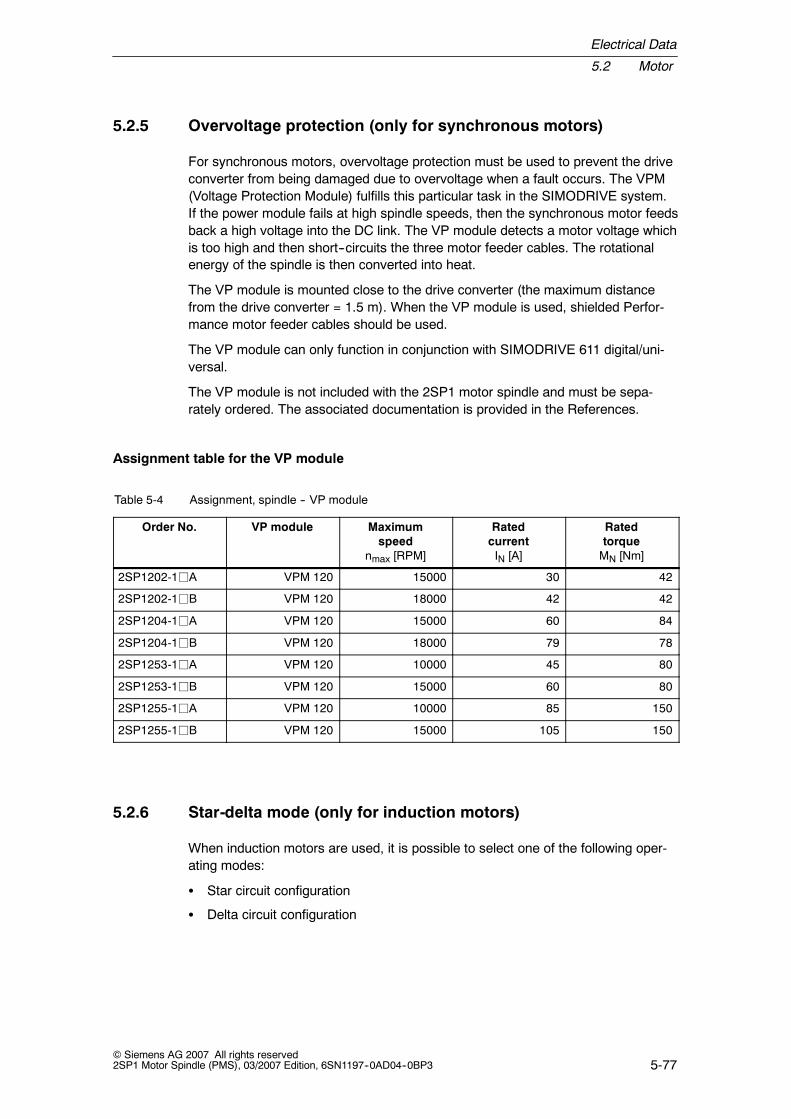
Electrical Data
5.2 Motor
5-77© Siemens AG 2007 All rights reserved2SP1 Motor Spindle (PMS), 03/2007 Edition, 6SN1197--0AD04--0BP3
5.2.5 Overvoltage protection (only for synchronous motors)
For synchronous motors, overvoltage protection must be used to prevent the driveconverter from being damaged due to overvoltage when a fault occurs. The VPM(Voltage Protection Module) fulfills this particular task in the SIMODRIVE system.If the power module fails at high spindle speeds, then the synchronous motor feedsback a high voltage into the DC link. The VP module detects a motor voltage whichis too high and then short--circuits the three motor feeder cables. The rotationalenergy of the spindle is then converted into heat.
The VP module is mounted close to the drive converter (the maximum distancefrom the drive converter = 1.5 m). When the VP module is used, shielded Perfor-mance motor feeder cables should be used.
The VP module can only function in conjunction with SIMODRIVE 611 digital/uni-versal.
The VP module is not included with the 2SP1 motor spindle and must be sepa-rately ordered. The associated documentation is provided in the References.
Assignment table for the VP module
Table 5-4 Assignment, spindle -- VP module
Order No. VP module Maximumspeed
nmax [RPM]
RatedcurrentIN [A]
RatedtorqueMN [Nm]
2SP1202-1jA VPM 120 15000 30 42
2SP1202-1jB VPM 120 18000 42 42
2SP1204-1jA VPM 120 15000 60 84
2SP1204-1jB VPM 120 18000 79 78
2SP1253-1jA VPM 120 10000 45 80
2SP1253-1jB VPM 120 15000 60 80
2SP1255-1jA VPM 120 10000 85 150
2SP1255-1jB VPM 120 15000 105 150
5.2.6 Star-delta mode (only for induction motors)
When induction motors are used, it is possible to select one of the following oper-ating modes:
S Star circuit configuration
S Delta circuit configuration

Electrical Data
5.2 Motor
5-78© Siemens AG 2007 All rights reserved
2SP1 Motor Spindle (PMS), 03/2007 Edition, 6SN1197--0AD04--0BP3
Circuit to implement a star-delta changeover
For induction motors, all six connection leads of the three winding phases are fedout to be able to select the various operating modes.
The changeover is carried--out outside the spindle using switching devices andequipment that are not included with the motor spindle (i.e. these devices are notincluded in the scope of supply.
For information on how the star-delta changeover is realized, please refer toFig. 5-2 and the Configuration Manual SIMODRIVE 611 Drive Converter.
Caution
A changeover may only be made when the spindle is in a no--load condition andwith the power module pulses inhibited.
Notice
When changing over the circuit configuration (star-delta), the appropriate data setfor the closed--loop motor control must also be changed--over.
Using the star circuit configuration
The star--circuit configuration offers some advantages at low speeds. The maxi-mum torque in the star circuit configuration is approximately twice as high as in thedelta circuit configuration. However, due to the higher reactive power requirementof the star circuit configuration, the available torque in the uppermost speed rangeis significantly restricted. This means that the star circuit configuration should onlybe activated when machining which requires a high torque in the lower speedrange. An example of such a machining operation is roughing.
Using the delta circuit configuration
Although the delta circuit configuration provides, in the lower speed range, a lowermaximum torque than the star circuit configuration, the torque remains available upto high speeds. This means that the delta circuit configuration should be activatedfor all machining operations which are carried--out in the average and highspeed ranges.

Electrical Data
5.2 Motor
5-79© Siemens AG 2007 All rights reserved2SP1 Motor Spindle (PMS), 03/2007 Edition, 6SN1197--0AD04--0BP3
Connection diagram for Y/D changeover
SIMODRIVE 611 digital system
MSD module
V2U2 W2 Term. 663PE
K2h
K2
K1Kx 1)
K2 K1
K1 Y
K1h
Y/∆
K1 K2
U2V1 W1 V2 W2U2
V2W2
Y/∆changeover
Pulseenable
from the
NC/PLC
K2hK1h
K2∆
U1
Kx 1)
EX.Y
Auxiliary contactorpower supply,max. 30 V DC
SINUMERIK 840 D
PLC outputs
AX.Y AX.Z
Fig. 5-2 Connection diagram for Y/D changeover with SIMODRIVE 611 digital
1) A safe operating stop is not guaranteed by just opening K1 and K2.This is the reason that for safety--related reasons, contactor K should be usedxto provide electrical isolation. This contactor may only be switched--in the no--current condition,i.e. the pulse enable must be withdrawn 40 ms before the contactor is opened (de--energized).

Electrical Data
5.2 Motor
5-80© Siemens AG 2007 All rights reserved
2SP1 Motor Spindle (PMS), 03/2007 Edition, 6SN1197--0AD04--0BP3
5.2.7 System overview and engineering information/instructions
System overview
2SP1 motor spindles are integrated into the SIMODRIVE drive system and suitablefor converter operation:
S SIMODRIVE 611 digital
S SIMODRIVE 611 universal
The SIMODRIVE 611 digital drive converter is controlled from the SINUMERIKfamilies 840 and 810D (CCU3 required for the spindles) via the drive bus.
The SIMODRIVE 611 universal drive converter also has a Profibus interface forcontrol via the SINUMERIK systems 840Di and 802D as well as a +/--10V interfaceto couple analog control systems.
SIMODRIVE611D
VPM
Bero for clamping systemM 3~
L1L2L3N
U2 V2 W2 9 663
T
17
X411
U1 V1 W1
I/R
810DCCU3
SIMATIC S7--300or
Basic I/O EFP
48 9
Q1
F1
T1
X304
X1
P24M
X1
2
U3 V3 W3
U4 V4 W4
X3
3
SITOPPOWER
Heat exchanger/cooling unit
Cooling on
Pneumatic
Discharge air
Tool change
OP 032MMC 100.2
alt.:OP 010PCU 20
Axis expansionEquip. bus
MPI
module
2SP1Motor spindle system
Fig. 5-3 System example with SINUMERIK 810 digital and SIMODRIVE 611 digital drive converters

Electrical Data
5.2 Motor
5-81© Siemens AG 2007 All rights reserved2SP1 Motor Spindle (PMS), 03/2007 Edition, 6SN1197--0AD04--0BP3
SIMODRIVE611universal
VPM
Bero for clamping system
M 3~
L1L2L3N
U2 V2 W2 9 663
T
17
X411
U1 V1 W1
I/R 802DPCU
Peripheral (I/O) module
PP 72/48
PROCESS FIELDBUS
X42348 9
Q1
F1
T1
X4
X2
X333
P24
M
X8
X1
2
U3 V3 W3
U4 V4 W4
X3
3
SITOPPOWER
Heat exchanger/cooling unit
Cooling on
Pneumatic
Discharge air
Tool change
2SP1
Equip. bus
Terminal stripconverter
Motor spindle system
Fig. 5-4 System example with SINUMERIK 802 and SIMODRIVE 611 universal drive converter
Dimensioning the power module
The power modules are selected and engineered according to the rated current INof the spindle, refer to Table 5-5 and Chapter 10
Table 5-5 Spindle -- drive converter assignment
Orderdesignation2SP1 motorspindle
Maxi-mumspeednmax[RPM]
Ratedcur-rent
IN [A]
Ratedtorque
MN [Nm]
Motortype
Powermodule[A]
OrderNo.
Power unit6SN1123-1AA00-..
2SP1202-1jAjj1 15000 30 42 Synch. 30/45/51 -0DA1
2SP1202-1jBjj2 18000 42 42 Synch. 45/60/76 -0LA1
2SP1204-1jAjj1 15000 60 84 Synch. 60/80/102 -0EA1
2SP1204-1jBjj2 18000 79 78 Synch. 85/110/127 -0FA1
2SP1253-8jAjj0 10000 1) 28 1) 70 1) Induct. 30/45/51 -0DA1
2SP1253-8jAjj1 15000 1) 28 1) 70 1) Induct. 30/45/51 -0DA1
2SP1255-8jAjj0 10000 1) 30 1) 140 1) Induct. 30/45/51 -0DA1
2SP1255-8jAjj1 15000 1) 30 1) 140 1) Induct. 30/45/51 -0DA1
2SP1253-1jAjj0 10000 53
(45)
100
(80)
Synch. 60/80/102
(45/60/76)
-0EA1
(-0LA1)
2SP1253-1jBjj1 15000 68
(60)
100
(80)
Synch. 85/110/127
(60/80/102)
-0FA1
(-0EA1)
2SP1255-1jAjj0 10000 95
(85)
170
(150)
Synch. 120/150/193
(85/110/127)
-0JA1
(-0FA1)
2SP1255-1jBjj1 15000 120 (105) 170 (150) Synch. 120/150/193 -0JA1
Values in brackets apply for operation with the next smaller power module.1) Overview of the spindle values for a star circuit, drive converter selection applies for both the star and
delta circuit configurations

Electrical Data
5.2 Motor
5-82© Siemens AG 2007 All rights reserved
2SP1 Motor Spindle (PMS), 03/2007 Edition, 6SN1197--0AD04--0BP3
Information regarding the spindle power data
Refer to Chapter 10 for the power data.
Information regarding synchronous motorsWhen using smaller (lower rating) power modules (refer to Table 5-5), then thecomplete speed range cannot be fully utilized (even when the motor has a reducedload). An additional field--weakening current is impressed from the rated speedonwards.Also refer to the appropriate characteristics (refer to Chapter 10) or contact yourlocal Siemens Office.A minimum current is required for the pole position identification. This means thatthe following must apply when selecting the power module and the motor:Rated current (S1 current), power unit -≥ 50 % rated motor current
Drive converter pulse frequenciesIn order to achieve optimum control characteristics, a minimum drive converterpulse frequency must be maintained which is a function of the maximum motorspeed.Minimum drive converter pulse frequency up to 15,000 RPM = 3.2 kHzMinimum drive converter pulse frequency up to 18,000 RPM = 4.0 kHz
De--rating the drive converter rated currentFor the drive converter, the rated current can depend on the pulse frequency andthe rotating frequency of the output current. When engineering 2SP1 motorspindles, a de--rating, dependent on the rotational frequency, must be applied forthe following drive converters (refer to Table 5-6).
Table 5-6 De--rating as a function of the rotational frequency (this only applies tosynchronous motors)
Drive converterOrder No.
Speed < 15,000 RPMNo derating
drive converter output current[A]
Speed > 15,000 RPMde--rating at ft = 4.0 kHz
(clock frequency)Drive converter output current
[A]
6SN1123-1AA00-0DA1 30/40/51 28/37/47
6SN1123-1AA00-0LA1 45/60/76 42/56/70
6SN1123-1AA00-0EA1 60/80/102 55/73/94
6SN1123-1AA00-0FA1 85/110/127 79/102/117
6SN1123-1AA00-0JA1 120/150/193 110/130/150
For additional information on the influence of the rotational and pulse frequency,refer to the Configuration Manual ”SIMODRIVE 611 Drive Converters” andSynchronous Built--in Motors 1FE1, Chapter ”Drive converter pulse frequencies,controller data and de--rating”.

Electrical Data
5.2 Motor
5-83© Siemens AG 2007 All rights reserved2SP1 Motor Spindle (PMS), 03/2007 Edition, 6SN1197--0AD04--0BP3
Information regarding the infeed/regenerative feedback unit
If an infeed unit is used without regenerative feedback, the braking power must bedissipated using pulsed resistors. These pulsed resistors must be appropriatelydimensioned. For information on the infeed/regenerative feedback unit, refer to theConfiguration Manual ”SIMODRIVE-611 Drive Converters”.
Spindle rating plate
420 Y
V A kW Nm Hz RPM
S1S6-40%
79120
3535
78110
113.3 43003000
max. 18000 RPMÜPmax = 2 kVEN 60034
TH.CL.FENCODER S01 256 pulses/revMade in Germany 2006
Motor type: 1FE1084--4WP51
3 ~ motor spindle2SP1204-1HB03-2DF2LZE-No.
Fig. 5-5 Spindle rating plate
Table 5-7 Translation for Fig. 5-5
English German
3~ motor spindle 3~ Motorspindel
TH.CL. F Wärmeklasse F
ENCODER Geber

Electrical Data
5.3 Connecting cables/connector assignments
5-84© Siemens AG 2007 All rights reserved
2SP1 Motor Spindle (PMS), 03/2007 Edition, 6SN1197--0AD04--0BP3
5.3 Connecting cables/connector assignments
5.3.1 Power connection
2SP1 motor spindles are connected to the power source through cables. The con-necting cables are 1.5 m long.
Table 5-8 Cable characteristics
Characteristics Characteristic values Remark
Cable type 1-conductor or 4-conductor, refer to Table 5-9
Draggable yes; carefully observe the minimum bending radius
Minimum bending radius Cable∅ x 10 mm
Cable∅ x 15 mm
Fixed routing
Draggable
Material 1-conductor cable:
4-conductor cable: PUR
e.g. PUR ...
e.g. PUR ...
Table 5-9 Power connection
Order designation
Motor
type
Circuit
Rated
current
I N Max.
speed
n max
Cross-
section,
conn.cable
Connectin
gcable
Max.
outer
diameter
Shield
[A] [RPM] [mm2] [mm]
2SP1202-1jAjj-1 Y 30 15000 10 4 x 1-cond. 10 Individual2)
2SP1202-1jBjj-2Synch
Y 42 18000 10 4 x 1-cond. 10 Individual2)
2SP1204-1jAjj-1Synch.
Y 60 15000 25 4 x 1-cond. 14 Individual2)
2SP1204-1jBjj-2 Y 79 18000 25 4 x 1-cond. 14 Individual2)
2SP1253 8jAjj 0Y 28
10000 1) 6 2 x 4 cond 16 Common1)2SP1253-8jAjj-0n 29
10000 1) 6 2 x 4-cond. 16 Common1)
2SP1253 8jAjj 1Y 28
10000 1) 6 2 x 4 cond 16 Common1)2SP1253-8jAjj-1
Inductn 29
10000 1) 6 2 x 4-cond. 16 Common1)
2SP1255 8jAjj 0
Induct.Y 30
10000 1) 6 2 x 4 cond 16 Common1)2SP1255-8jAjj-0n 29
10000 1) 6 2 x 4-cond. 16 Common1)
2SP1255 8jAjj 1Y 30
10000 1) 6 2 x 4 cond 16 Common1)2SP1255-8jAjj-1n 29
10000 1) 6 2 x 4-cond. 16 Common1)
2SP1253-1jAjj-0 Y 45 10000 10 4 x 1-cond. 10 Individual2)
2SP1253-1jBjj-0Synch
Y 60 15000 16 4 x 1-cond. 12 Individual2)
2SP1255-1jAjj-0Synch.
Y 85 10000 25 4 x 1-cond. 14 Individual2)
2SP1255-1jBjj-1 Y 105 15000 35 4 x 1-cond. 16 Individual2)
1) 4-conductor cable with common shield2) PE cable without shield

Electrical Data
5.3 Connecting cables/connector assignments
5-85© Siemens AG 2007 All rights reserved2SP1 Motor Spindle (PMS), 03/2007 Edition, 6SN1197--0AD04--0BP3
5.3.2 Direction of rotation
The direction of rotation of the spindle is defined when the power cables are con-nected to the drive converter.
Table 5-10 Connecting the cables for a clockwise direction of rotation
Cable designation, spindle Connection designation,SIMODRIVE 611 drive
converter
Direction of rotation ofthe spindle when viewing
the drive side
U1 or conductor designation 1 U2
V1 or conductor designation 2 V2
W1 or conductor designation 3 W2
Drive end
Table 5-11 Connecting the cables for a counter--clockwise direction of rotation
Cable designation, spindle Connection designation,SIMODRIVE 611 drive
converter
Direction of rotation ofthe spindle when viewing
the drive side
U1 or conductor designation 1 V2
V1 or conductor designation 2 U2
W1 or conductor designation 3 W2
Drive end
!Warning
The drive converter rotating field must match the direction in which the encodersystem counts. When connecting--up as specified in Table 5-11, the direction inwhich the encoder system counts must be adapted using the appropriate machinedata; MD 1011 is used to make this adaptation for SIMODRIVE 611digital/universal.
If the rotating field and counting direction of the encoder system do not match,then this can result in uncontrollable motion and destruction of the motor spindle.

Electrical Data
5.3 Connecting cables/connector assignments
5-86© Siemens AG 2007 All rights reserved
2SP1 Motor Spindle (PMS), 03/2007 Edition, 6SN1197--0AD04--0BP3
Reference: SIMODRIVE 611 digital, Description of FunctionsDrive functions,Chap. 2.1 Configuration, actual value sensing (motor meas. system)
SINUMERIK 840D/SIMODRIVE 611 digital,Commissioning ManualChapter 6.9.10, Position controller data, axis
J

6-87© Siemens AG 2007 All rights reserved2SP1 Motor Spindle (PMS), 03/2007 Edition, 6SN1197--0AD04--0BP3
Supplying the Various Media
6.1 Overview, supplying the various media
2SP120
Clamp/release tool,
2SP125
hydraulicallyClamp/release tool,
pneumatically
External tool cooling with cooling--lubricating medium, refer toChapter 6.6
Air purge, pneumatic
Clamp/release tool,pneumatically
Sealing air
Refer to Chapter 6.4
Compressed air, refer toChapter 6.3
Air purge, pneumatic
Sealing air
Refer to Chapter 6.5
Motor cooling Motor cooling
Refer to Chapter 6.2
Internal tool cooling withcooling--lubricating medium
Internal tool cooling withcooling--lubricating medium
= Option
Fig. 6-1 Overview, supplying the various media
6

Supplying the Various Media
6.2 Cooling medium
6-88© Siemens AG 2007 All rights reserved
2SP1 Motor Spindle (PMS), 03/2007 Edition, 6SN1197--0AD04--0BP3
6.2 Cooling medium
The spindle is designed for water cooling. The spindle housing is equipped withcooling ducts, which transfer the stator power loss (heat) into the cooling water.The temperature of the cooling water increases when it flows through the spindlecorresponding to the flow rate and the thermal power that it absorbs.
∆T = 1V.⋅ Ã ⋅ cp
⋅ PV
∆T = Temperature difference between the cooling water input and output
V.
= Cooling water flow rateρ = Density of the cooling watercp = Specific thermal capacitance of the cooling waterPV = Power loss that has been absorbed
Notice
In order to guarantee the necessary thermal transition in the cooling ducts, theminimum cooling water flow, listed in Chapter 9, should be maintained.
Note
Higher cooling water flow rates are permissible as long as the permissiblehydrostatic pressure in the system is not exceeded.

Supplying the Various Media
6.2 Cooling medium
6-89© Siemens AG 2007 All rights reserved2SP1 Motor Spindle (PMS), 03/2007 Edition, 6SN1197--0AD04--0BP3
6.2.1 Cooling water connections
Table 6-1 Cooling water connections
2SP120 2SP125 Remark
Connection fitting Hose connector for hose∅ 12/10 mm
G1/2” (inner thread) forhoses ∅ 9 mm
On the spindle side
Connection code I = motor cooling ONII = motor cooling OFF
I = motor cooling ONII = motor cooling OFF
On the spindle side
Permitted tighteningtorque [Nm]
---- max. 100 Nm When tightening
Notice
The feeder lines and hoses to the connections must be flexible and strain relieved.Rigid pipe connections are not permissible.
For the connectors of the 2SP120VV spindle, only use connecting hoses in aPU/PA quality.
6.2.2 Conditioning the cooling water
The cooling water must be conditioned in order to maintain the correct functioningof the cooling system on the spindle side (refer to Table 6-2).
Table 6-2 Conditioning the cooling water
Value
Min. incoming temperature No moisture condensation
Max. incoming temperature Without de--rating 25 °C
With de--rating, refer to Table 6-3: 40 ° C
Max. hydrostatic pressure 5 bar
Max. particle size 100 µm
Recommended anti--corrosion agents max. 25% Clariant, Antifrogen or Tyfocor

Supplying the Various Media
6.2 Cooling medium
6-90© Siemens AG 2007 All rights reserved
2SP1 Motor Spindle (PMS), 03/2007 Edition, 6SN1197--0AD04--0BP3
Caution
Cooling
S It is neither permissible to use water from the drinking water supply, nor
S to use cooling--lubricating medium.
The cooling water temperature must be set corresponding to the ambienttemperature so that moisture condensation does not occur.
The S1 power (continuous duty) of the spindle depends on the inlet temperature ofthe cooling water. For inlet temperatures of up to 25°C the S1 power, specified inthe data sheet, is achieved. Above a cooling water inlet temperature of 25°C, theS1 power is reduced (refer to Table 6-3).
Table 6-3 Reduced S1 power as a function of the cooling--water temperature
Inlet temperature [°C] Reduction factor
25 1
35 0.95
40 0.90
Cooling water additives
Additives must be added to the cooling water to protect against corrosion and livingorganisms. These additives must be compatible with the materials used for thecooling water feed system on the spindle side. Further, they must also be compat-ible with the materials used in the cooling water feed system on the machine side.Electro--chemical incompatibility between the materials of the cooling water feedand the spindle side and on the machine side is not permissible. The machine--sidecooling water feed system must be appropriately designed.
List of materials for the cooling water feed on the spindle side:
S Steel, grey cast iron
S Brass
S Stainless steel
S Viton
S GFP
Cooling water requirements
Refer to Chapter 10 for the flow quantity and pressure drop.

Supplying the Various Media
6.2 Cooling medium
6-91© Siemens AG 2007 All rights reserved2SP1 Motor Spindle (PMS), 03/2007 Edition, 6SN1197--0AD04--0BP3
6.2.3 Cooling systems
The cooling water that is withdrawn from the spindle must be cooled using an ex-ternal cooling system. The external cooling system is not included with the spindle.
The thermal load of the cooling water at the rated spindle power is described inSection 10.
Table 6-4 External cooling system versions
Version Characteristics
The existing cooling systemis used
-- The existing cooling system must be increased by thespindle power loss
-- The compatibility of the materials must be carefullychecked
-- The pump must be able to provide the additional flow atthe required pressure
Air/water heat exchangercooling system
-- Favorable investment and operating costs as a compres-sor does not have to be used
-- The heat exchanger must be dimensioned so that theinlet temperature for the spindle is a max. 5 K above theambient temperature
-- Higher space requirement of the heat exchanger than forthe cooling unit
Stand--alone coolingsystem
-- The inlet temperature for the spindle is independent ofthe ambient temperature
Cooling system manufacturersTable 6-5 Cooling system manufacturers
BKW Kälte--Wärme--Versorgungstechnik GmbH
Benzstraße 2
72649 Wolfschlungen
Tel.: +49 (0) 70 22 -- 50 03 -- 0
Telefax: +49 (0) 70 22 -- 50 03 -- 30
mailto:[email protected]
http://www.bkw.kuema.de
DELTATHERM Hirmer GmbH
Gewerbegebiet Bövingen 122
53804 Much
Tel.: +49 (0) 22 45 -- 61 07 -- 0
Telefax: +49 (0) 22 45 -- 61 07 -- 10
mailto:[email protected]
http://www.deltatherm.de

Supplying the Various Media
6.2 Cooling medium
6-92© Siemens AG 2007 All rights reserved
2SP1 Motor Spindle (PMS), 03/2007 Edition, 6SN1197--0AD04--0BP3
Table 6-5 Cooling system manufacturers, continued
Glen Dimplex Deutschland GmbH, Geschäftsbereich RIEDEL Kältetechnik
Am Goldenen Feld 18
95326 Kulmbach
Tel.: +49 (0) 92 21 -- 709 --555
Telefax: +49 (0) 92 21 -- 709 --549
mailto:[email protected]
http://www.riedel--cooling.de
Hydac System GmbH
Postfach 1251
66273 Sulzbach/Saar
Tel.: +49 (0) 68 97 -- 509 -- 708
Telefax: +49 (0) 68 97 -- 509 -- 454
http://www.hydac.com
Helmut Schimpke Industriekühlanlagen GmbH & Co. KG
Ginsterweg 25 -- 27
42781 Haan
Tel.: +49 (0) 21 29 -- 94 38 -- 0
Telefax: +49 (0) 21 29 -- 94 38 -- 99
mailto:[email protected]
http://www.schimpke.de
Hyfra Industriekühlanlagen GmbH
Industriepark 54
56593 Krunkel
Tel.: +49 (0) 26 87 -- 898 -- 0
Telefax: +49 (0) 26 87 -- 898 -- 25
mailto:[email protected]
http://www.hyfra.de
KKT Kraus Kälte-- und Klimatechnik
Mühllach 11
90552 Röthenbach a. d. Pegnitz
Tel.: +49 (0) 911 -- 953 33 -- 40
Telefax: +49 (0) 911 -- 953 33 -- 33
http://www.kkt--kraus.de

Supplying the Various Media
6.2 Cooling medium
6-93© Siemens AG 2007 All rights reserved2SP1 Motor Spindle (PMS), 03/2007 Edition, 6SN1197--0AD04--0BP3
Table 6-5 Cooling system manufacturers, continued
Pfannenberg GmbH
Werner--Witt--Straße 1
21035 Hamburg
Tel.: +49 (0) 40 734 12 -- 127
Telefax: +49 (0) 40 734 12 -- 101
http://www.pfannenberg.de

Supplying the Various Media
6.3 Compressed air
6-94© Siemens AG 2007 All rights reserved
2SP1 Motor Spindle (PMS), 03/2007 Edition, 6SN1197--0AD04--0BP3
6.3 Compressed air
6.3.1 Using compressed air
The functions, listed in Table 6-6 use compressed air.
Table 6-6 Using compressed air
Functions usingcompressed air
Description
Actuating the pneumaticcylinder
-- The tool is clamped in and released from the tool holderusing the pneumatic cylinder
-- The minimum pressure must be maintained
-- Compressed air is only used when clamping andreleasing the tool
-- Particles in the compressed air are relatively non--critical
Bearing sealing air -- A high degree of purity is required (refer to Chapter6.3.3)
-- A continuous airflow is required
Air purge -- Protects the tool holder from becoming dirty -- betweenejecting the old tool and inserting the new tool
-- Purge air is only used while the tool is being changed
-- An average degree of purity is required
It is the responsibility of the machinery construction company/operating companyto provide the compressed air in the required quality and quantity. The machineryconstruction company is responsible in controlling the individual compressed airflows.

Supplying the Various Media
6.3 Compressed air
6-95© Siemens AG 2007 All rights reserved2SP1 Motor Spindle (PMS), 03/2007 Edition, 6SN1197--0AD04--0BP3
Pneumatic cylinder(tool ejection/clamping)
Throttle
Sealing air
Air purge
PLC
Spindle unit
Air filter mesh
Air filter mesh
∅ di≥ 8 mm
∅ di≥ 8 mm
∅ di≥ 8 mm
∅ di≥ 8 mm
≦ 6 bar
= 2.5 to 3 bar
50 µm
8 µm
≧ 5 bar
To clean chips fromthe tool tool holder
To release orclamp tool
Compressedair input
Fig. 6-2 Recommended pneumatic system
Table 6-7 Translation for Fig. 6-2
English German
Air purge Kegelreinigungsluft
Spindle unit Spindeleinheit
Pneumatic cylinder (tool ejection) Pneumatischer Zylinder (Ausstoß des Werk-zeuges)
Sealing air Sperrluft
Throttle Drossel
To clean chips from the tool holder Reinigung der Werkzeugaufnahme vonSpänen
To release or clamp tool Lösen oder Spannen des Werkzeuges
Air filter mesh Luftfilterfeinheit
Compressed air supply Drucklufteingang

Supplying the Various Media
6.3 Compressed air
6-96© Siemens AG 2007 All rights reserved
2SP1 Motor Spindle (PMS), 03/2007 Edition, 6SN1197--0AD04--0BP3
6.3.2 Compressed air connections
All of the connections are compressed air feed connections (inlet). The com-pressed air which has been used is discharged to the environment.
Table 6-8 Compressed air connections for 2SP120
Pneumatic cylinder Sealing air Airpurge
Function Release tool,air inlet
Clamp tool,air inlet
Air inlet Air purge inlet
Connection fitting(on the spindle side)
1 x G1/4”(inner thread) forhoses∅≥ 8 mm
1 x G1/8”(inner thread) forhoses∅≥ 8 mm
Radial: G1/8”(inner thread)
Axial: ∅ 5.0 mm(provide a 6 x2 mm O ring) forhoses∅≥ 8 mm
G1/4”(inner thread) forhoses∅≥ 8 mm
Connection code (on thespindle side) 1)
VIIa VIIIa V IX
Perm. tightening torque 30 Nm 20 Nm 20 Nm 40 Nm
Table 6-9 Compressed air connections for 2SP125
Pneumatic cylinder Sealing air Airpurge
Function Release tool,air inlet
Clamp tool,air inlet
Air inlet Air purge inlet
Connection fitting(on the spindle side)
M16 x 1.5(inner thread) forhoses∅≥ 8 mm
G1/8”(inner thread) forhoses∅≥ 8 mm
Radial: G1/8”(inner thread) forhoses∅≥ 8 mm
G1/4”(inner thread) forhoses∅≥ 8 mm
Connection code (on thespindle side) 1)
X XI V IXa
Perm. tightening torque 30 Nm 20 Nm 20 Nm 40 Nm
Notice
The feeder lines and hoses to the connections must be flexible and strain relieved.Rigid pipe connections are not permissible.
1) Connection codes, also refer to the dimension sheets, Chapter 10

Supplying the Various Media
6.3 Compressed air
6-97© Siemens AG 2007 All rights reserved2SP1 Motor Spindle (PMS), 03/2007 Edition, 6SN1197--0AD04--0BP3
6.3.3 Conditioning the compressed air
In addition to the different minimum requirements placed on the supply of the com-pressed air functions, the conditions, listed in Table 6-11 must be maintained.
Table 6-10 General compressed air conditioning
Min. air inlet temperature [°C] Ambient temperature
Max. air inlet temperature 35 °C
Max. residual water content 0.12 g/m3
Max. residual oil content 0.01 mg/m3
Max. residual dust 0.1 mg/m3
Table 6-11 Conditioning
Minimum pressure[pa]
Maximum pressure[pa]
Max. particle size[µm]
Pneumatic cylinder 5⋅105 (5 bar) 10⋅105 (10 bar) 50
Sealing air 2.5⋅105 (2.5 bar) 3⋅105 (3 bar) 8
Air purge 5⋅105 (5 bar) 6⋅105 (6 bar) 50

Supplying the Various Media
6.3 Compressed air
6-98© Siemens AG 2007 All rights reserved
2SP1 Motor Spindle (PMS), 03/2007 Edition, 6SN1197--0AD04--0BP3
6.3.4 Hydraulic fluid flow data and controlling the hydraulic fluid flowrequirement
The compressed air functions should only be switched--in when actually required inorder to minimize the air requirement.
Notice
The sealing air must be permanently active to protect the bearings as long as themotor spindle is operational.
Table 6-12 Air requirement
Compressed airfunction
Air flow requirement [Nl] Controlling the air flowrequirement
Pneumatic cylinder Air usage per tool change
2SP120 800 cm3/cycle
2SP125 846 cm3/cycle
Flow rate only when changing atool (releasing and clamping)
Air purge 2.1 Nm3/h for 5 tool changesper minute.
Compressed air only has to beswitched--in when the old tool isejected up to when the new tool isdrawn--in
Sealing air 1--1.5 Nm3/h 1) The compressed air must beswitched--in when the machine ispowered--up
1) 1 Nm3= standard cubic meters

Supplying the Various Media
6.3 Compressed air
6-99© Siemens AG 2007 All rights reserved2SP1 Motor Spindle (PMS), 03/2007 Edition, 6SN1197--0AD04--0BP3
6.3.5 Standalone units to generate compressed air
An external compressor must be used to provide the compressed air and appropri-ately condition it. The compressor equipment is not included with the spindle.
If the machine construction company uses a separate compressor, storage deviceand pressure controller for the compressed air generating system, then the struc-ture, as shown in Fig. 6-3, is recommended.
Air filterWaterseparator
Radiator
Compressor
Motor
M
ManometerThrottlevalve
Pressurereservoir
Non--returnvalve
Pressurerelief valve
Electricpressureswitch
Fig. 6-3 Recommended circuit--diagram of a compressed air system
Table 6-13 Translation for Fig. 6-3
English German
Pressure switch Druckschalter
Throttle Drosselventil
Manometer Manometer
Water separator Wasserabscheider
Non--return valve Rückschlagventil
Pressure reservoir Druckluftspeicher
Pressure relief valve Druckbegrenzungsventil
Compressor Kompressor
Cooler Kühler
Motor Motor
Air filter Luftfilter

Supplying the Various Media
6.4 Hydraulic (option, only for 2SP120)
6-100© Siemens AG 2007 All rights reserved
2SP1 Motor Spindle (PMS), 03/2007 Edition, 6SN1197--0AD04--0BP3
6.4 Hydraulic (option, only for 2SP120)
6.4.1 Using hydraulics
Hydraulics is used to clamp and release the tool holder.
Table 6-14 Using hydraulics
Hydraulic functions Description
Actuating the hydrauliccylinder
-- The tool is clamped in the tool holder and released fromit using the hydraulic cylinder
-- The minimum pressure must be maintained
-- Hydraulics are only required when clamping andreleasing the tool
-- Particles in the compressed air are relatively non--critical
The machinery construction OEM is responsible for:
S Providing the required quality and quantity of hydraulic fluid
S Controlling the individual hydraulic fluid flows
PLC
Spindle unit
∅ di≥ 5 mm
≧ 50--80 bar
To release or toclamp tool
Hydraulic cylinder(tool ejection/clamping)
Hydraulic pump
Hydraulic filtermesh 100 µm
Hydraulic pressurereservoir
Non--returnvalve
Hydraulic tank
Pressurerelief valve
Fig. 6-4 Recommended hydraulic system layout

Supplying the Various Media
6.4 Hydraulic (option, only for 2SP120)
6-101© Siemens AG 2007 All rights reserved2SP1 Motor Spindle (PMS), 03/2007 Edition, 6SN1197--0AD04--0BP3
Table 6-15 Translation for Fig. 6-2
English German
Spindle unit Spindeleinheit
Hydraulic cylinder (tool ejection/clamping) Hydraulik Zylinder (Lösen/Spannen desWerkzeuges)
To release or to clamp tool Lösen oder Spannen des Werkzeuges
Hydraulic filter mesh Ölfilterfeinheit
Hydraulic pump Hydraulikpumpe
Hydraulic tank Hydrauliktank
Non--return valve Rückschlagventil
Hydraulic pressure reservoir hydraulischer Druckspeicher
6.4.2 Hydraulic connections
All of the connections only comprise a hydraulic fluid feed.
Table 6-16 Technical data to control the hydraulics of the hydraulic cylinder
Hydraulic cylinder
Function Release tool Clamp tool
Connection fitting (on the spindle side) G1/4” G1/4”
Connection code (on the spindle side) 1) VII VIII
Perm. tightening torque 40 Nm 40 Nm
Release/clamping pressure 50 to 80 bar
Max. particle size 100 µm
Notice
The feeder lines and hoses to the connections must be flexible and strain relieved.Rigid pipe connections are not permissible.
6.4.3 Hydraulic fluid flow data and controlling the hydraulic fluid flowrequirement
The hydraulic functions should only be switched--in when actually required in orderto minimize oil usage.
1) Connection codes, also refer to the dimension sheets, Chapter 10

Supplying the Various Media
6.5 Internal tool cooling using the cooling--lubricating medium (option)
6-102© Siemens AG 2007 All rights reserved
2SP1 Motor Spindle (PMS), 03/2007 Edition, 6SN1197--0AD04--0BP3
6.5 Internal tool cooling using the cooling--lubricatingmedium (option)
The 2SP1 motor spindle is optionally available with the internal tool cooling func-tion. In this case, cooling--lubricating medium is fed through a rotary gland from therear of the shaft through the spindle shaft to the tool. The user must appropriatelycondition and provide this cooling--lubricating medium in order to guarantee theservice lifetime of the rotary gland.
The ”internal tool cooling with cooling--lubricating medium” can only be retrofittedwith the spindle removed and only by an authorized repair workshop.
Table 6-17 Connecting the internal tool cooling
Cooling--lubricatingmedium inlet
Leakage drain
Connection fitting (on the spindle side) G1/4” (inner thread) G1/8” (inner thread)
Connection code (on the spindle side) for 2SP120 Xfor 2SP125 IXb
IV
Permissible tightening torque [Nm] 40 20
Caution
It is not permissible to use a rigid pipe connections.
The piping must be free of any tension and pressure as well as bending torqueand torsion. The piping may not be subject to tensile stress -- neither whenpressurized nor under a no--pressure condition.
The piping may not exert any torsion on the connection fitting of thecooling--lubricating medium feed. Flexible hoses with the appropriate loop must beused to make the connection.
Notice
Small cooling--lubricating medium leaks will occur in operation, especially whentools are being changed. The leaked cooling--medium fluid is collected in thecooling--lubricating medium gland and from where it can drain.
The fluid must be able to freely drain from the pipes.

Supplying the Various Media
6.5 Internal tool cooling using the cooling--lubricating medium (option)
6-103© Siemens AG 2007 All rights reserved2SP1 Motor Spindle (PMS), 03/2007 Edition, 6SN1197--0AD04--0BP3
Max. 50 bar
-/16/13(ISO 4406)
VentDrain
Keep linesshort
G1/8”
G1/4”
Cooling-lubricatingmedium
Minimum cooling-lubricating quantity
Fig. 6-5 Connections for various media
Table 6-18 Translation for Fig. 6-5
English German
Minimum cooling-lubricating quantity Minimalmengen-Kühlschmierung
Cooling-lubricating medium Kühlschmiermittel
Vent Entlüftung
Drain Leckage
Keep lines short Leitung kurz halten

Supplying the Various Media
6.5 Internal tool cooling using the cooling--lubricating medium (option)
6-104© Siemens AG 2007 All rights reserved
2SP1 Motor Spindle (PMS), 03/2007 Edition, 6SN1197--0AD04--0BP3
Screw-in depthmax. 8 mm
Ensure that thereis no backwash
Fig. 6-6 Drain connection
Table 6-19 Translation for Fig. 6-6
English German
Screw-in depth Einschraubtiefe
Ensure that there is no backwash rückstaufrei abführen
6.5.1 Operating conditions
The data in Table 6-20 apply for the cooling--lubricating medium flow when thespindle is being operated.
Table 6-20 Data of the cooling--lubricating medium gland
Value Remark
Max. pressure 50·105 Pa (50 bar)
Max. speed 18000 rpm Also under no pressureconditions
Max. particle size 50 µm Cooling--lubricating me-dium acc. to ISO 4406(--/16/13)
Max. cooling--lubricating mediumtemperature
40 °C
Max. flow rate 54 l/min Dependent on the pres-sure
Pressure loss 2.7·105 Pa(2.7 bar)
Frictional torque 0.3 Nm
The frictional torque of the cooling--lubricating medium gland means that its tem-perature increases and reduces the available maximum torque.

Supplying the Various Media
6.5 Internal tool cooling using the cooling--lubricating medium (option)
6-105© Siemens AG 2007 All rights reserved2SP1 Motor Spindle (PMS), 03/2007 Edition, 6SN1197--0AD04--0BP3
Table 6-21 Permissible media for the internal tool cooling
Operation with cooling--lubricatingmedium
The flow must be guaranteed
Operation with minimum quantity ofli l b i ti di
Mixture, maximum 5 barcooling-lubricating medium
Lubricating medium percentage, minimum 10 ml/h
Lubrication must be guaranteed
2/2path valve must allow unrestricted flow (as thefluids could possibly separate) (e.g. ball valve)
Cooling--lubricating medium and compressed airmay never be simultaneously applied to the MQLsystem
Dry machining without compressedair
The line must be vented; there may be no residualpressure
When changing a tool, to clean the tool cone/nose at standstill, compressed air canbe fed--in through the integrated cooling--lubricating medium gland.
Caution
The cooling--lubricating medium must be conditioned so that pressure peaks in thefeeder line are avoided. The maximum permissible pressure may never beexceeded -- even during pressure peaks.
The integrated cooling--lubricating medium gland is not suitable to feed--inhydraulic fluids and compressed air while the spindle is rotating.
Only suitable tools with a through hole which allows the cooling--lubricatingmedium to be discharged may be used when feeding--in cooling--lubricatingmedium for internal tool cooling; there must always be a transfer pipe to connectthe tool to the clamping system so that no fluid is lost.
If unsuitable tools are used, then the grease is flushed--out of the tool gripper and,depending on the pressure, can cause failure of the spindle or the rotary gland.

Supplying the Various Media
6.6 External tool cooling with cooling--lubricating medium
6-106© Siemens AG 2007 All rights reserved
2SP1 Motor Spindle (PMS), 03/2007 Edition, 6SN1197--0AD04--0BP3
6.6 External tool cooling with cooling--lubricating medium(option, only for 2SP120j)
The 2SP120jmotor spindle is optionally available with the ”external tool cooling”function. The ”external tool cooling with cooling--lubricating medium” function canalso be retrofitted on spindles that have already been supplied.
The ”external tool cooling” function is implemented using a ring that is mounted atthe motor spindle flange. The ring is available with adjustable spray nozzles or withthreaded holes so that customer--specific spray nozzles can be used.
The cooling--lubricating medium is fed--in either through an axial or radial connec-tion at the stationary mounting flange of the spindle. The connection that is notused must be sealed.
The cooling--lubricating medium jet can be aligned using the manually adjustablespray nozzles so that the cooling--lubricating medium cools the tool and the work-piece from the outside. In order to guarantee the function of the spray nozzles, theuser must appropriately condition the cooling--lubricating medium (refer to Chapter6.6.1).
6 adjustable spray nozzles
Radial connection forcooling-lubricating medium inlet
Axial connection forcooling-lubricatingmedium inlet
Retaining holes for mounting the ring to the spindle
Radial connection forcooling-lubricatingmedium inlet
Threaded hole forcustomer--specificspray nozzles
Axial connectionfor cooling-lubricatingmedium inlet
Fig. 6-7 Lefthand side: Ring with the adjustable spray nozzles for the external tool cooling;Righthand side: Ring with threaded holes to screw--in spray nozzles or chain elements for theexternal tool cooling

Supplying the Various Media
6.6 External tool cooling with cooling--lubricating medium
6-107© Siemens AG 2007 All rights reserved2SP1 Motor Spindle (PMS), 03/2007 Edition, 6SN1197--0AD04--0BP3
Table 6-22 Translation for Fig. 6-7
English German
6 adjustable spray nozzles 6 einstellbare Spritzdüsen
Radial connection for cooling-lubricatingmedium inlet
radialer Anschluss der Kühlschmiermittelzu-fuhr
Axial connection for cooling-lubricating me-dium inlet
axialer Anschluss der Kühlschmiermittelzu-fuhr
Retaining holes for mounting the ring to thespindle
Befestigungsbohrungen für den Anbau desRings an die Spindel
Threaded hole for customer--specific spraynozzles
Gewindebohrungen für kundenspezifischeSpritzdüsen
Table 6-23 Connection for the external tool cooling (for 2SP120)
Connection, cooling--lubricating inlet
Axial Radial
Connection fitting (on the spindleside)
Bore ∅ 8.8 mm pre-pared for 11 x 2 mmO ring
G1/4” (inner thread)
Connection code(on the spindle side) 1)
XI XI
Perm. tightening torque -- 40 Nm
Cooling--lubricating medium outlet viaadjustable spray nozzles (standard)
6 spray nozzles, adjustable from 0--30_
Cooling--lubricating medium outletthrough threaded holes for customer--specific spray nozzles (option)
Threaded holes 8 x G1/4”
Caution
It is not permissible to use a rigid pipe connections. The piping must be free of anytension and pressure as well as bending torque and torsion.
The piping may not be subject to tensile stress -- neither when pressurized norunder no--pressure conditions.The piping may not exert any torsion on the connection fitting of thecooling--lubricating medium feed.
Flexible hoses with the appropriate loop must be used to make the connection.
1) Connection codes, also refer to the dimension sheets, Chapter 10

Supplying the Various Media
6.6 External tool cooling with cooling--lubricating medium
6-108© Siemens AG 2007 All rights reserved
2SP1 Motor Spindle (PMS), 03/2007 Edition, 6SN1197--0AD04--0BP3
6.6.1 Operating conditions
The data in Table 6-24 apply for the cooling--lubricating medium flow when thespindle is being operated.
Table 6-24 Data of the external tool cooling with cooling--lubricating medium
Value Remark
Max. pressure 5·105 Pa (5 bar)
Max. particle size 50 µm Cooling--lubricatingmedium acc. to ISO 4406(--/16/13)
Max. cooling--lubricating mediumtemperature
40 °C
Max. flow rate Dependent on thepressure
Caution
The cooling--lubricating medium must be conditioned so that pressure peaks areavoided. The maximum permissible pressure may not be exceeded.

Supplying the Various Media
6.7 Media connections and coding
6-109© Siemens AG 2007 All rights reserved2SP1 Motor Spindle (PMS), 03/2007 Edition, 6SN1197--0AD04--0BP3
6.7 Media connections and coding
6.7.1 Media connections for 2SP120j
Table 6-25 Media connections for 2SP120V (on the spindle side)
Description 2SP120V
Coding 1) Connection fitting
Motor cooling inlet Ι G1/2” connector for hoses∅≥ 12/10 mm
Motor cooling outlet ΙΙ G1/2” connector for hoses∅≥ 12/10 mm
Sealing air inlet V G1/8” radial or axis through a ∅5 mm diameter bore for 6 x 2 mmseal
Release tool, air inlet VΙΙa 1 x G1/4”
Clamp tool, air inlet VΙΙΙa 1 x G1/8”
Release tool, hydraulic inlet VΙΙ G1/4”
Clamp tool, hydraulic inlet VΙΙΙ G1/4”
Air purge inlet ΙX G1/4”
Internal tool cooling with cooling--lubricatingmedium
Cooling--lubricating medium inlet
Leakage drain
X
ΙVG1/4”
G1/8”
External tool cooling with cooling--lubricatingmedium
Cooling--lubricating medium inlet
Leakage drain
XI
ΙV
G1/4” radial or axis through a∅ 8.8 mm diameter bore for 11 x2 mm seal
G1/8”
= Option
1) Connection codes, also refer to the dimension sheets, Chapter 10

Supplying the Various Media
6.7 Media connections and coding
6-110© Siemens AG 2007 All rights reserved
2SP1 Motor Spindle (PMS), 03/2007 Edition, 6SN1197--0AD04--0BP3
Releasetool air inlet
Remove
Clamp toolair inlet
Air purge
Don’t remove
Fig. 6-8 ECS--M pneumatic 2SP120j--1Hj2j--jjjj without rotary gland
Table 6-26 Translation for Fig. 6-8
English German
Release tool air inlet Luft für ”Werkzeug lösen”
Remove entfernen
Clamp tool air inlet Luft für ”Werkzeug spannen”
Air purge Kegelreinigungsluft
Don’t remove nicht entfernen

Supplying the Various Media
6.7 Media connections and coding
6-111© Siemens AG 2007 All rights reserved2SP1 Motor Spindle (PMS), 03/2007 Edition, 6SN1197--0AD04--0BP3
Remove
Internal toolcooling
Drain must be openduring operation
Fig. 6-9 ECS--M pneumatic 2SP120j--1Hj2j--jjjj with rotary gland
Table 6-27 Translation for Fig. 6-8
English German
Remove entfernen
Internal tool cooling Werkzeuginnenkühlung
Drain must be open during operation Leckage darf bei Betrieb nicht verschlossensein

Supplying the Various Media
6.7 Media connections and coding
6-112© Siemens AG 2007 All rights reserved
2SP1 Motor Spindle (PMS), 03/2007 Edition, 6SN1197--0AD04--0BP3
Clamp toolhydraulicsinlet Remove
Air purge
Don’t removeRelease toolhydraulics inlet
Fig. 6-10 ECS--M hydraulic 2SP120j--1Hj3j--jjjj without rotary gland
Table 6-28 Translation for Fig. 6-8
English German
Clamp tool hydraulics inlet Hydraulik für ”Werkzeug spannen”
Remove entfernen
Air purge Kegelreinigungsluft
Don’t remove nicht entfernen
Release tool hydraulics inlet Hydraulik für ”Werkzeug lösen”

Supplying the Various Media
6.7 Media connections and coding
6-113© Siemens AG 2007 All rights reserved2SP1 Motor Spindle (PMS), 03/2007 Edition, 6SN1197--0AD04--0BP3
Drain must be openduring operation
Remove
Internal toolcooling
Fig. 6-11 ECS--M hydraulic 2SP120j--1Hj3j--jjjj with rotary gland
Table 6-29 Translation for Fig. 6-8
English German
Remove entfernen
Internal tool cooling Werkzeuginnenkühlung
Drain must be open during operation Leckage darf bei Betrieb nicht verschlossensein

Supplying the Various Media
6.7 Media connections and coding
6-114© Siemens AG 2007 All rights reserved
2SP1 Motor Spindle (PMS), 03/2007 Edition, 6SN1197--0AD04--0BP3
Sealing air
External cooling-lubricatingmedium
-- If axial connection is useddon’t remove
-- If radial connection isused, please remove andseal axial with an O-ring
Fig. 6-12 ECS--M 2SP120j optional external cooling--lubricating medium
Table 6-30 Translation for Fig. 6-12
English German
Sealing air Sperrluft
If axial connection is used don’t remove Bei axialem Anschluss nicht entfernen
If radial connection is used, please removeand seal axial with an O-ring
Bei radialem Anschluss entfernen und axialmit O-Ring abdichten
External cooling-lubricating medium Externes Kühlschmiermittel

Supplying the Various Media
6.7 Media connections and coding
6-115© Siemens AG 2007 All rights reserved2SP1 Motor Spindle (PMS), 03/2007 Edition, 6SN1197--0AD04--0BP3
6.7.2 Media connections for 2SP125j
Table 6-31 Media connections for 2SP125V (on the spindle side)
Description 2SP125V
Coding 1) Connection fitting
Motor cooling inlet Ι G1/2”
Motor cooling outlet ΙΙ G1/2”
Sealing air inlet V G1/8”
Release tool, air inlet X M16 x 1.5
Clamp tool, air inlet XΙ G1/8”
Air purge inlet ΙXa G1/4”
Internal tool cooling with cooling--lubricatingmedium
Cooling--lubricating medium inlet
Leakage drain
ΙXb
ΙVG1/4”
G1/8”
= Option
1) Connection codes, also refer to the dimension sheets, Chapter 10
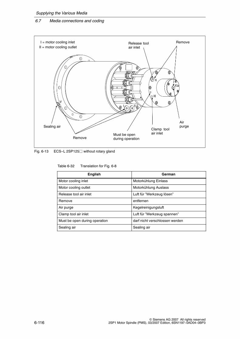
Supplying the Various Media
6.7 Media connections and coding
6-116© Siemens AG 2007 All rights reserved
2SP1 Motor Spindle (PMS), 03/2007 Edition, 6SN1197--0AD04--0BP3
Sealing air
Remove
Remove
Must be openduring operation
Airpurge
Clamp toolair inlet
Release toolair inlet
I = motor cooling inletII = motor cooling outlet
Fig. 6-13 ECS--L 2SP125j without rotary gland
Table 6-32 Translation for Fig. 6-8
English German
Motor cooling inlet Motorkühlung Einlass
Motor cooling outlet Motorkühlung Auslass
Release tool air inlet Luft für ”Werkzeug lösen”
Remove entfernen
Air purge Kegelreinigungsluft
Clamp tool air inlet Luft für ”Werkzeug spannen”
Must be open during operation darf nicht verschlossen werden
Sealing air Sealing air
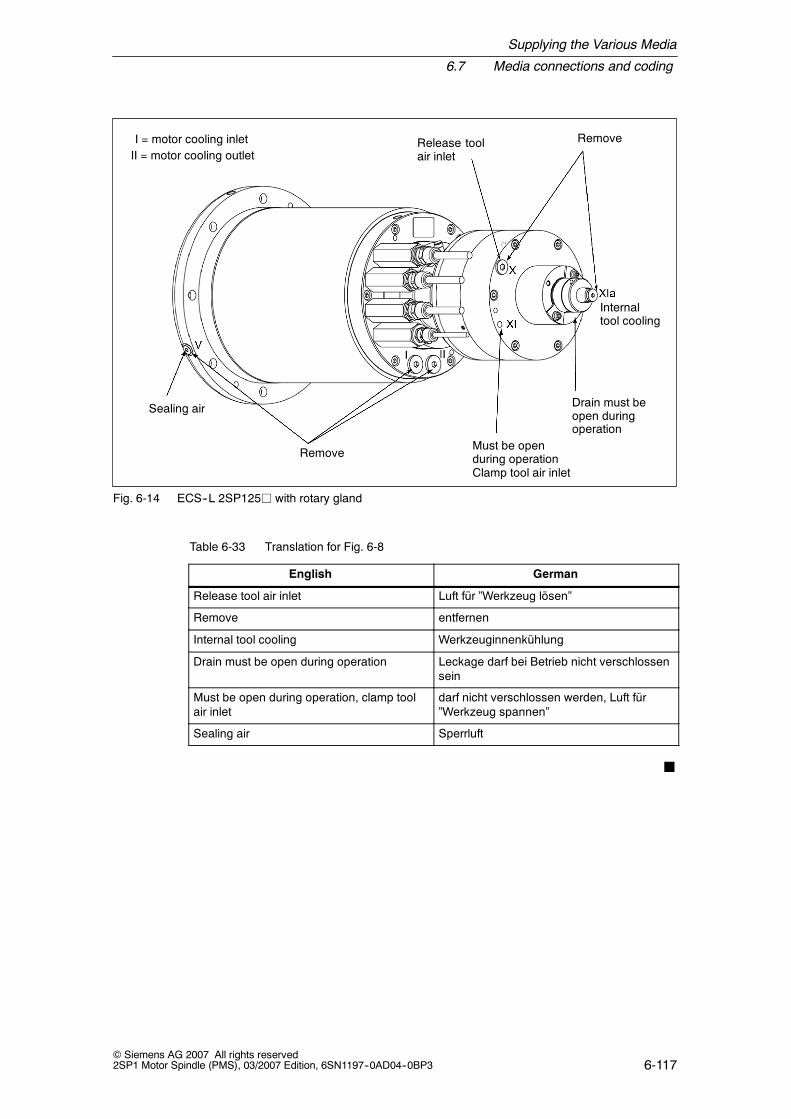
Supplying the Various Media
6.7 Media connections and coding
6-117© Siemens AG 2007 All rights reserved2SP1 Motor Spindle (PMS), 03/2007 Edition, 6SN1197--0AD04--0BP3
Sealing air
Remove
RemoveRelease toolair inlet
Internaltool cooling
Drain must beopen duringoperation
Must be openduring operationClamp tool air inlet
I = motor cooling inletII = motor cooling outlet
Fig. 6-14 ECS--L 2SP125j with rotary gland
Table 6-33 Translation for Fig. 6-8
English German
Release tool air inlet Luft für ”Werkzeug lösen”
Remove entfernen
Internal tool cooling Werkzeuginnenkühlung
Drain must be open during operation Leckage darf bei Betrieb nicht verschlossensein
Must be open during operation, clamp toolair inlet
darf nicht verschlossen werden, Luft für”Werkzeug spannen”
Sealing air Sperrluft
J

Supplying the Various Media
6.7 Media connections and coding
6-118© Siemens AG 2007 All rights reserved
2SP1 Motor Spindle (PMS), 03/2007 Edition, 6SN1197--0AD04--0BP3
Space for your notes
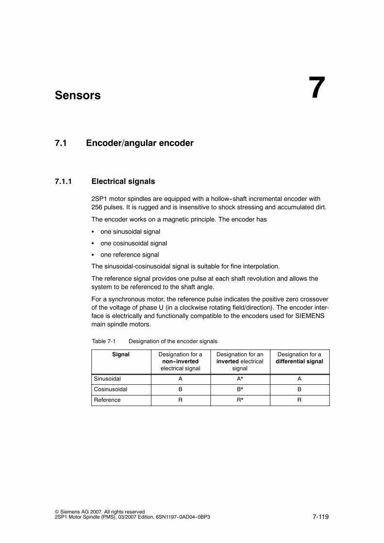
7-119© Siemens AG 2007 All rights reserved2SP1 Motor Spindle (PMS), 03/2007 Edition, 6SN1197--0AD04--0BP3
Sensors
7.1 Encoder/angular encoder
7.1.1 Electrical signals
2SP1 motor spindles are equipped with a hollow--shaft incremental encoder with256 pulses. It is rugged and is insensitive to shock stressing and accumulated dirt.
The encoder works on a magnetic principle. The encoder has
S one sinusoidal signal
S one cosinusoidal signal
S one reference signal
The sinusoidal-cosinusoidal signal is suitable for fine interpolation.
The reference signal provides one pulse at each shaft revolution and allows thesystem to be referenced to the shaft angle.
For a synchronous motor, the reference pulse indicates the positive zero crossoverof the voltage of phase U (in a clockwise rotating field/direction). The encoder inter-face is electrically and functionally compatible to the encoders used for SIEMENSmain spindle motors.
Table 7-1 Designation of the encoder signals
Signal Designation for anon--invertedelectrical signal
Designation for aninverted electrical
signal
Designation for adifferential signal
Sinusoidal A A* A
Cosinusoidal B B* B
Reference R R* R
7

Sensors
7.1 Encoder/angular encoder
7-120© Siemens AG 2007 All rights reserved
2SP1 Motor Spindle (PMS), 03/2007 Edition, 6SN1197--0AD04--0BP3
Electrical signals
The signal data comprises, electrically, two individual signals -- an inverted and anon--inverted signal. The individual signals have a DC voltage component with amagnitude of half of the encoder power supply voltage. The differential signal of1 Vpp is obtained in the encoder interface of the drive converter by subtracting theindividual signals (refer to Fig. 7-1). As a result of this subtraction, the DC voltagecomponent of the signal track disappears and the signal amplitude doubles withrespect to the individual signal.
This differential signal is relevant for the subsequent encoder evaluation. The fea-tures and properties of the differential signal are described in the following.
Signalvoltage
t [ms]
[V]
0
--1
--2
--3
1
2
3
[Signal+]
[Signal--]
(differential voltage)Peak--peak
Signalvoltage
360_ electrical angle
[Signal+] -- [Signal--]
DC voltage component(=1/2 Vsupply)
Fig. 7-1 Electrical signal level
Table 7-2 Translation for Fig. 7-1
English German
Signal voltage Signalspannung
Peak-peak signal voltage Signalspannung Spitze--Spitze
Electrical angle Winkel, elektrisch
Signal Signal
DC voltage component Gleichspannungsanteil
Differential voltage Differenzspannung

Sensors
7.1 Encoder/angular encoder
7-121© Siemens AG 2007 All rights reserved2SP1 Motor Spindle (PMS), 03/2007 Edition, 6SN1197--0AD04--0BP3
Phase position of the reference signal
The phase position of the maximum of the reference signal is centered betweenthe sinusoidal and cosinusoidal signals. The maximum deviation from the theoreti-cal value is designated, in the encoder data table, as clear signal range α (refer toFig. 7-2).
Phase position of the sinusoidal-cosinusoidal signals
There is a 90° phase offset between the sinusoidal and cosinusoidal signals. Themaximum deviation from the theoretical value is designated as β in the encoder--data table (refer to Fig. 7-2).
Tolerances, position R--A/B
Amplitude
[V]
Angle [_ electrical]Reference 0
Track A Track B Track R
Fig. 7-2 Clear signal range of the reference track; phase relationship between the sinusoidal and cosi-nusoidal signal
Table 7-3 Translation for Fig. 7-2
English German
Tolerances, position R--A/B Toleranzen, Lage R--A/B
Track A, B, R Spur A, B, R
Reference Bezug
Angle [_ electrical] Winkel [_ elektrisch]

Sensors
7.1 Encoder/angular encoder
7-122© Siemens AG 2007 All rights reserved
2SP1 Motor Spindle (PMS), 03/2007 Edition, 6SN1197--0AD04--0BP3
DC voltage offsetThe signals can have a DC voltage offset (refer to Fig. 7-3). The maximum offsetvoltages of the two incremental signals (sin, cos) and the reference signal are spe-cified in the encoder data table.
Signalvoltage
t [ms]
[V]
0
--0.2
--0.4
--0.6
0.2
0.4
0.6
A (differential voltage)
B (differential signal)
R (differential voltage)
Differential signal offset voltage
Differential signaloffset voltage ofR signal
Differentialsignalvoltage
ofRsignal
Fig. 7-3 Offset voltages of the encoder signals
Table 7-4 Translation for Fig. 7-3
English German
Signal voltage Signalspannung
Differential signal voltage of R signal R-Signal Differenzspannung
Differential signal Differenzsignal
Differential signal offset voltage Offsetspannung Differenzsignal
Differential signal offset voltage of R signal R-Signal Offsetspannung (Differenzsignal)
Differential voltage Differenzspannung
Table 7-5 Electrical data of the incremental encoder
Remark Units Characteristic values
Supply voltage V 5 +/--5%
Supply current mA 40 (typical)
Min. Typical Max.
Signal amplitude (A ; B) Differential signal Vpp 0.75 1.00 ... 1.10 1.20
Signal ratio (A ; B) 0.9 0.95 ... 1.05 1.1
Phase offset β Between A and B _ el. --5 --2 ... +2 +5
Signal offset Differential signal mV --60 --15 ... +15 +60
Signal voltage R Differential signal V 0.4 1.0 1.2
Offset R signal mV --400 --450 --500
Clear signal range α _ el. --200 --160... +160 +200

Sensors
7.1 Encoder/angular encoder
7-123© Siemens AG 2007 All rights reserved2SP1 Motor Spindle (PMS), 03/2007 Edition, 6SN1197--0AD04--0BP3
7.1.2 Connecting the signal lines
The signal cable is connected through a 17--pin flange--mounted socket. Pre--assembled cables should be used to connect the encoder to the drive converter.
SpindleConverter
25--pinSub D
17--pinSub D
6FX8002--2CA80--1hh0 for 2SP120V/2SP125V 1)
Fig. 7-4 Signal cable without the temperature sensor brought out
SpindleConverter
17--pinSub D
6FX8002--2CA31--1hh0 for 2SP120V
Adapter 6FX8002--1AA51--1hhh
3RT.... temperature sensor PTC, NTC coupled--out
25--pinSub D
Fig. 7-5 Signal cable with the temperature sensors, PTC, NTC brought out
Table 7-6 Translation for 7-4 and 7-5
English German
Converter Umrichter
Spindle Spindel
Temperature sensor coupled--out Auskopplung Temperaturfühler
1) This avoids signals from the additional temperature sensors for third--party systems frombeing coupled--into the closed--loop control

Sensors
7.1 Encoder/angular encoder
7-124© Siemens AG 2007 All rights reserved
2SP1 Motor Spindle (PMS), 03/2007 Edition, 6SN1197--0AD04--0BP3
PIN assignment
Table 7-7 PIN assignment for the encoder connection (17--pin flange--mounted socket)
PIN No. Conductorcolor
Signal View of the connector side
1 Blue A
2 Red A*
3 Green R
4 Brown PTC, NTC K227 2)
5 White/brown NTC K227, NTC PT3-51F 2)
6 White NTC PT3-51F 2)43
7 Black M encoder4
523
1413
8 Black +KTY 84 1) 61
1417
1512
9 White -- KTY 84 1) 79
11
1 1516
10 White P encoder 8910
11 Gray B
12 Yellow B*
13 Brown R*
14 White PTC 2)
15 Violet 0 V sense
16 Orange 5 V sense
17 not connected
For additional information on the signal cables, refer to Catalog NC 60, Chapter”Connection system”.
1) 2-conductor temperature sensor cable2) Connections, additional temperature sensors for spindle 2SP120VV3) This avoids signals from the additional temperature sensors for third--party systems from
being coupled--into the closed--loop control

Sensors
7.2 Clamping state sensors
7-125© Siemens AG 2007 All rights reserved2SP1 Motor Spindle (PMS), 03/2007 Edition, 6SN1197--0AD04--0BP3
7.2 Clamping state sensors
Function description, refer to Chapter 4.5.Integration into the control, refer to Chapter 7.
7.2.1 Analog and digital sensors of the 2SP120 spindle
Information on the sensor systems to monitor the tool clamped status -(analog sensor S1) and to monitor the position of the piston of the release unit(digital sensor S4).
Connection
Connectors are used to connect--up the sensors (refer to drawings,Chapter 10)
The cables that are used to connect--up the sensors are not included with thespindle. These cables are commercially available as standard products.
Table 7-8 Electrical data and mechanical design of the connector for the clamping statesensor
Sensor S1 to display the clamped state (analog)
Type Analog sensor
BN
BK
BU
+
--
1 = +24 V2 = not assigned3 = 0 V4 = analog signal
12
3 4
Output signal 0 ... 10 V
Operating voltage 15 ... 30 VDC
Rated operating voltage 24 V DC
Nominal clearance 3 mm
Residual ripple ± 15% of Ve
Max. linearity error ¦ 3% of Va
Max. operating point offset ¦ 0.3 mm
Linearity range 1 ... 5 mm
Connection Connector
Short--circuit protection Yes
Incorrect polarity protection Yes
Connector (plug) at the cable end(on the spindle side)
Binder series 763, 4 pins, 763-09-3431-116-04
Connector (socket) at the sensor cable Type, Siemens Axial: 3RX1535Radial: 3RX1548 (with LED)
Type Balluff Axial: BKS-S19-4Radial: BKS-S20-4 (with LED)

Sensors
7.2 Clamping state sensors
7-126© Siemens AG 2007 All rights reserved
2SP1 Motor Spindle (PMS), 03/2007 Edition, 6SN1197--0AD04--0BP3
The precise voltage values for the clamped states ”draw bar in the release posi-tion”, ”tool clamped” and ”clamped without tool” are specified in the acceptancereport of the particular spindle.
Table 7-9 Electrical data and mechanical design of the connector for the clamping statesensor(digital)
Sensor S1, S2, S3 to display the clamped state (digital)
Pin assignment at the sensor Connector at thesensor
Socket at the cable
12
3 4
1: +V2: not assigned3: --V4: switching contact
BN
BK
BU
+
Type, Siemens with connectoroutlet
Axial: 3RX1535
Radial: 3RX1548 (with LED)
Type, Balluff with connector outlet
Axial: BKS-S19-4
Radial: BKS-S20-4 (with LED)BU
-- Plug contacts Socket contacts
M12 x 1 M12 x 1
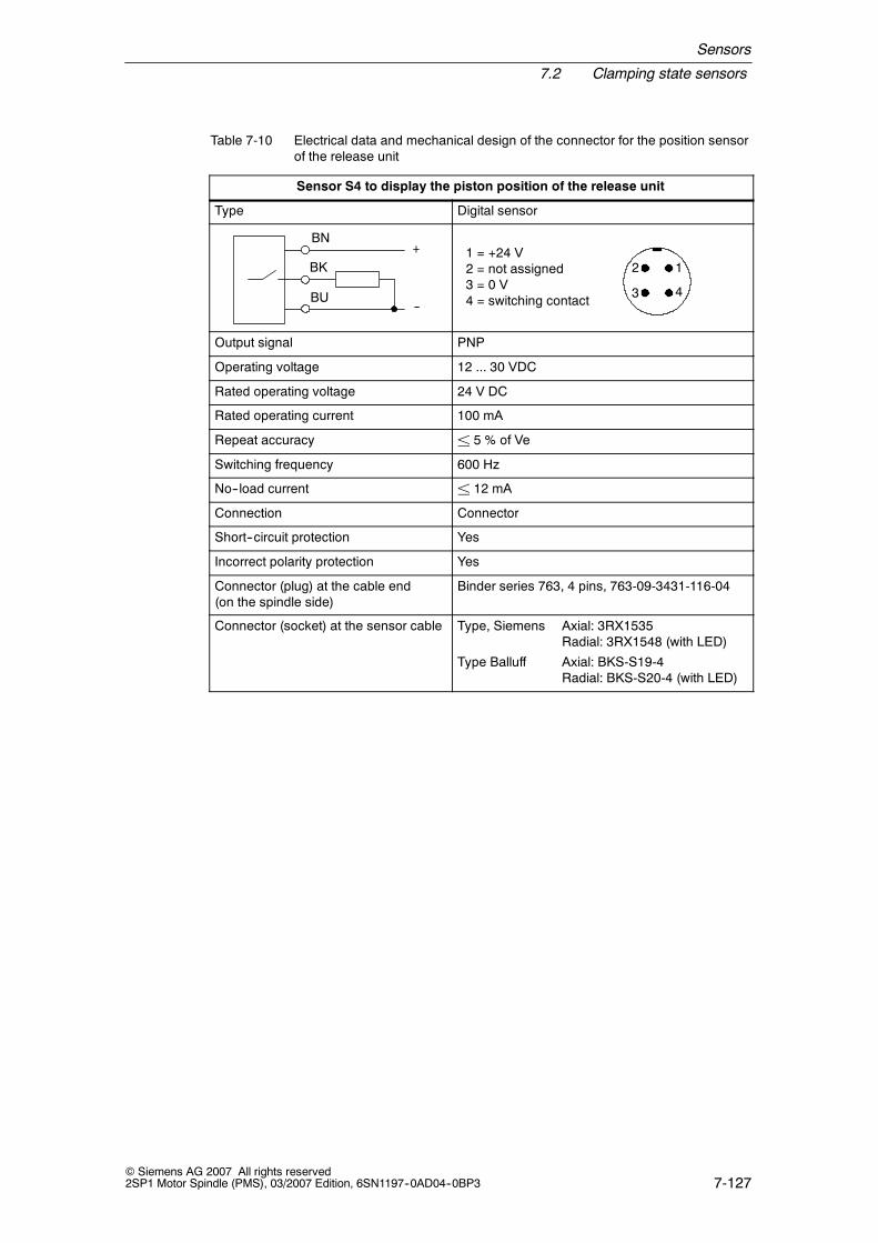
Sensors
7.2 Clamping state sensors
7-127© Siemens AG 2007 All rights reserved2SP1 Motor Spindle (PMS), 03/2007 Edition, 6SN1197--0AD04--0BP3
Table 7-10 Electrical data and mechanical design of the connector for the position sensorof the release unit
Sensor S4 to display the piston position of the release unit
Type Digital sensor
BN
BK
BU
+
--
1 = +24 V2 = not assigned3 = 0 V4 = switching contact
12
3 4
Output signal PNP
Operating voltage 12 ... 30 VDC
Rated operating voltage 24 V DC
Rated operating current 100 mA
Repeat accuracy ± 5 % of Ve
Switching frequency 600 Hz
No--load current ± 12 mA
Connection Connector
Short--circuit protection Yes
Incorrect polarity protection Yes
Connector (plug) at the cable end(on the spindle side)
Binder series 763, 4 pins, 763-09-3431-116-04
Connector (socket) at the sensor cable Type, Siemens Axial: 3RX1535Radial: 3RX1548 (with LED)
Type Balluff Axial: BKS-S19-4Radial: BKS-S20-4 (with LED)

Sensors
7.2 Clamping state sensors
7-128© Siemens AG 2007 All rights reserved
2SP1 Motor Spindle (PMS), 03/2007 Edition, 6SN1197--0AD04--0BP3
7.2.2 Digital sensors of 2SP125 spindles
Information on the sensor system to monitor the tool clamped status (digital sen-sors S1, S2 and S3).
Table 7-11 Electrical implementation of the clamping status sensors
Supply 0 V PIN 3
+ 24 V Max. tolerance±20 %Current demand < 40 mA plus the loadcurrent
PIN 1
Switchingcontact
Switches to thepos. supplyvoltage
Active (H) PIN 4
Switches to thehigh--ohmicstate
Inactive (L)
Load capacityof the switch-ing contact
200 mA max.
The following voltages are notpermissible:
Greater than 5 V below the voltage at PIN 3and greater than 5 V above the voltage atPIN 1
When an inductive load is connected toPIN 4, an appropriate measure must beprovided to limit the voltage.
(PIN 4)
Connection
Contactless transistor switches with 3--wire connection are used for the clampingstatus sensors. Connectors are used to connect--up the sensors (refer to drawings,Chapter 10).
The cables that are used to connect--up the sensors are not included with thespindle. These cables are commercially available as standard products.
Table 7-12 Mechanical implementation of the plug--in connection
Pin assignment at the sensor Connector at thesensor
Socket at the cable
12
3 4
1: +V2: not assigned3: --V4: switching contact
BN
BK
BU
+
Type, Siemens with connectoroutlet
Axial: 3RX1535
Radial: 3RX1548 (with LED)
Type, Balluff with connector outlet
Axial: BKS-S19-4
Radial: BKS-S20-4 (with LED)BU
-- Plug contacts Socket contacts
M12 x 1 M12 x 1

Sensors
7.3 Thermal sensors/motor protection
7-129© Siemens AG 2007 All rights reserved2SP1 Motor Spindle (PMS), 03/2007 Edition, 6SN1197--0AD04--0BP3
7.3 Thermal sensors/motor protection
KTY 84 PTC thermistors are used to sense the motor temperature.These PTC thermistors are suitable to measure temperatures in an analog fashion.
Additional temperature sensors to sense the motor temperature using NTC therm-istors are included in the 2SP120 spindle; they can be used together with third--party systems. Further, the 2SP120 spindle has additional temperature sensorsthat allow full motor protection to be implemented (e.g. for loads that are appliedwhen the spindle is stationary or at low speeds).
Temperature evaluation using KTY 84
For SIMODRIVE 611 drive converters, an external tripping device to evaluate themotor temperature is not required. The PTC thermistor function is monitored.
1. Pre--alarm temperature
When the pre--alarm temperature is exceeded, the drive converter signals thisusing an appropriate fault signal.
This message must be externally evaluated.
The signal is withdrawn if the motor temperature < pre--alarm temperature.
2. Motor limit temperature
When the motor limiting temperature is exceeded, the drive converter shutsdown and signals this using an appropriate fault message.
Table 7-13 Technical data of the KTY 84 NTC thermistor
Designation Description
Type KTY 84
Resistance when cold (20 _C) approx. 580 Ω
Resistance when warm (100 _C) approx. 1000 Ω
Connection via signal cable (please observe the polarity!)
Temperature characteristic
3
2
0
1
0200 300100 υU [°C]
ID = 2 mA
R [kΩ]

Sensors
7.3 Thermal sensors/motor protection
7-130© Siemens AG 2007 All rights reserved
2SP1 Motor Spindle (PMS), 03/2007 Edition, 6SN1197--0AD04--0BP3
Temperature evaluation using NTC thermistors (spindle 2SP120)
Both NTC K227 and NTC PT3--51F thermistors are included as standard and areused if the drive converter cannot evaluate the KTY thermistor.
The drive converter senses and evaluates the motor temperature using the sensorsignal (refer to the drive converter documentation).
Table 7-14 Technical data, NTC K227 and NTC PT3-51
Designation Technical data
NTC K227 NTC PT3-51F
PTC resistance (25 _C) approx. 32.8 kΩ approx. 49.1 kΩ
Resistance when warm (100 _C) approx. 1800 Ω approx. 3300 Ω
Connection Via signal cable
Temperature characteristic
NTC thermistor NTC PT3-51F
01020304050607080
10 30 50 70 90 110 130 150 170 190Temperature [°C]
Resistance[kOhm
]
NTC thermistor K227/33k/A1
0
10
20
30
40
50
60
10 30 50 70 90 110 130 150 170 190Temperature [°C]
Resistance[kOhm
]

Sensors
7.3 Thermal sensors/motor protection
7-131© Siemens AG 2007 All rights reserved2SP1 Motor Spindle (PMS), 03/2007 Edition, 6SN1197--0AD04--0BP3
Temperature evaluation using a PTC thermistor triplet (spindle 2SP120)
The PTC thermistor triplet must be evaluated using an external tripping/evaluationunit (this is not included in the scope of supply). This means that the sensor cableis monitored for wire breakage and short--circuit by this unit.
The PTC signals must be retrieved (refer to Chapter -) close to the spindle usingan intermediate connector or a terminal box.
The motor must be switched into a no--torque condition when the response tem-perature is exceeded.
Table 7-15 Technical data of the PTC thermistor triplet
Designation Technical data
Type (acc. to DIN 44082--M180) PTC thermistor triplet
PTC resistance (20 _C) ≤ 750 Ω
Resistance when warm (180 _C) ≥ 1710 Ω
Response temperature 180 _C
Connection Using an external evaluation unit, e.g.3RN1013-1GW10
Note: The PTC thermistors do not have a linear characteristic and are thereforenot suitable to determine the instantaneous temperature.

Sensors
7.3 Thermal sensors/motor protection
7-132© Siemens AG 2007 All rights reserved
2SP1 Motor Spindle (PMS), 03/2007 Edition, 6SN1197--0AD04--0BP3
Temperature monitoring machining--side bearings (spindle 2SP120)
The PT100 resistance sensor can be optionally ordered for the spindle 2SP120j.
The PT100 resistance sensor is used for
S Monitoring the bearing temperature
S Compensating the thermal length growth of the spindle (expansion)
The corresponding PT100 evaluation units must be used to make the evaluation.The connection is made using the signal cable.
Temperature [°C]
Resistance[kOhm
]
10030
130
20
120
110
100
140
40 50 60 70 80 90
Fig. 7-6 Temperature characteristic PT100
J

8-133© Siemens AG 2007 All rights reserved2SP1 Motor Spindle (PMS), 03/2007 Edition, 6SN1197--0AD04--0BP3
Control
The central machine control (PLC) controls the following:
S The spindle
S The tool change mechanism
S The supply equipment and devices
The power--on and operating conditions for correct spindle operation are listed inthe following.
8.1 Conditions that enable the spindle to rotate
Table 8-1 Enable signals for spindle rotation
Message/sensor interrogation Required status Remarks
Motor temperature TKTY84 < 150 °C KTY 84 (integratedmotor temperature sensor)
Spindle cooling S Cooling medium temperaturein the reference range
S Cooling medium flow rate inthe reference range
Refer to Chapter 6.2.2
Pressure at the tool clamping andrelease unit
Pressure to clamp the tool is inthe reference range 1)
The release cylinder piston is notin contact with the spindle shaft 2)
Refer to Chapter 4.5
Sealing air Input pressure in the referencerange
Refer to Chapter 6.3.3
Clamping state sensors Tool is clamped Refer to Chapter 4.5
!Warning
The machinery construction OEM must evaluate the sensor signals that can thenbe used to check the required states in order to permit the spindle to rotate (e.g.permissive signal). The spindle must be stopped if one of the enable conditions isno longer present.
1) The reference pressure depends on whether the motor spindle is equipped with apneumatic or a hydraulic release unit.
2) For 2SP120 motor spindles, the position of the piston in the clamped state is additionallymonitored using a sensor. This must display the following state: Tool clamping and re-lease unit in the ”clamped” end position.
8

Control
8.2 Clamping state sensors
8-134© Siemens AG 2007 All rights reserved
2SP1 Motor Spindle (PMS), 03/2007 Edition, 6SN1197--0AD04--0BP3
8.2 Clamping state sensors
The tool is clamped or ejected using the pulling or pushing force of the draw bar.When clamping or ejecting the tool, the draw bar always assumes an appropriateposition in the axial direction. The clamping state is linked with the axial position ofthe draw bar and is interrogated using this (refer to Fig. 8-1).
8.2.1 Clamping state sensors 2SP120VV
Basic version with analog sensors
Sensor S1 Analog sensor to detect the tool clamped stateSensor S4 Digital sensor to detect the position of the release cylinder
S1
S1
S1
clamped without toolVoltage level3
clamped with tool
draw bar in release positionVoltage level1
Position of draw bar
S4 piston in end positionH (+24V)
Voltage level2
End stop of draw bar for”tool is clamped” state
End stop of draw bar”clamped withouttool” state
End stop ofdraw bar for”release tool”
Pulling movement of draw bar for ”clamp tool”
Pushing movement of draw barfor ”release tool”
Analogsensor
Digital
sensor
Fig. 8-1 Signal assignment of sensors S1 and S4 for 2SP120

Control
8.2 Clamping state sensors
8-135© Siemens AG 2007 All rights reserved2SP1 Motor Spindle (PMS), 03/2007 Edition, 6SN1197--0AD04--0BP3
Table 8-2 Translation for Fig. 8-1
English German
Sensor S1, Sensor S4 Sensor S1, Sensor S4
End stop of draw bar for ”release tool” Endposition der Zugstange bei ”Werkzeuglösen”
Position of draw bar Position der Zugstange
End stop of draw bar for ”tool is clamped”state
Halteposition der Zugstange im Zustand”Werkzeug gespannt”
Pushing movement of draw bar for ”re-lease tool”
drückende Bewegung der Zugstange bei”Werkzeug lösen”
Pulling movement of draw bar for ”clamptool”
ziehende Bewegung der Zugstange bei”Werkzeug spannen”
End stop of draw bar ”clampedwithout tool” state
Endposition der Zugstange bei ”gespanntohne Werkzeug”
Voltage level x Spannungspegel
clamped without tool gespannt ohne Werkzeug
clamped with tool gespannt mit Werkzeug
draw bar in release position Zugstange in Löseposition
piston in end position Zylinderkolben in Endlage
Notice
Under extreme machining conditions signal faults and disturbances can occur inoperation.
Nominal states of S1 and S4
Table 8-3 Nominal states of S1(for precise values, refer to the acceptance report for the particular spindle)
State Voltage [V]
Draw bar in the release position ² 8.5 V
Tool clamped 1.5 to 4.5 V
Clamped without tool 1±0.2 V
Table 8-4 Nominal states of S4
State Signal level: High, Low
Release piston at the back (status, tool clamped) H
Release piston at the front (status, tool released) L

Control
8.2 Clamping state sensors
8-136© Siemens AG 2007 All rights reserved
2SP1 Motor Spindle (PMS), 03/2007 Edition, 6SN1197--0AD04--0BP3
Signals from S1 and S4
Table 8-5 Signals from the analog sensor regarding the tool clamping state and the digital sensor for the position ofthe release piston
State S1analog
S4digital
PLC action Possible fault causes
Draw bar in the releaseposition, release piston atthe front 1)
Highestvoltage level²8.5 V 2)
L -- Enable signal to allow a tool tobe changed after a defined de-lay time
Draw bar in the releaseposition, release piston atthe back 1)
Highestvoltage level²8.5 V 2)
H -- The spindle is not enabled forrotation
-- No enable signal to change thetool
-- The clamping systemjams
-- Defective sensors
Clamp toolthe correct clamping posi-tion has not been reached
Averagevoltage level>4.5 to 8.5 V 2)
L -- The spindle is not enabled forrotation
-- No enable signal to change thetool
Normal case at the transitionfrom clamping/releasing
In case of fault-- The release piston jams-- Incorrect function of theswitching valve
Clamp toolthe correct clamping posi-tion has not been reached
Averagevoltage level>4.5 to 8.5 V 2)
H -- The spindle is not enabled forrotation
-- No enable signal to change thetool
Normal case at the transitionfrom releasing/clamping
In case of fault-- Foreign body in the toolholder
-- Tool that is not in com-pliance with the stan-dard
-- Tool does not match thetool interface of thespindle
Tool clamped, correctclamping positionreached, release pistonstill at the shaft
Lowvoltage level1.5 to 4.5 V 2)
L -- The spindle is not enabled forrotation
-- No enable signal to change thetool
Normal case at the transitionfrom releasing/clamping
In case of fault-- The release piston jams
Tool clamped, the correctclamping position hasbeen reached, releasepiston at the back
Lowvoltage level1.5 to 4.5 V 2)
H -- The spindle is enabled for rota-tion after a defined waiting time
-- No enable signal to change thetool
Draw bar is tensioned,but the clamping positionwas exceeded
Lowestvoltage level<1.5 V 2)
L -- The spindle is not enabled forrotation
-- No enable signal to change thetool
-- A tool has not beenclamped
-- Tool that is not in com-pliance with the stan-dard
-- Release piston still notat the end position
Draw bar is tensioned,but the clamping positionwas exceeded
Lowestvoltage level<1.5 V 2)
H -- The spindle is not enabled forrotation
-- No enable signal to change thetool
-- A tool has not beenclamped
-- Tool that is not in com-pliance with the stan-dard
-- Release piston at itsend stop
1) Notice: Jammed tools cannot be reliably detected with sensor S12) The specified values are nominal values. The exact values are specified in the acceptance report of the
particular spindle

Control
8.2 Clamping state sensors
8-137© Siemens AG 2007 All rights reserved2SP1 Motor Spindle (PMS), 03/2007 Edition, 6SN1197--0AD04--0BP3
Basic version with digital sensors
Sensor S1 Digital sensor to sense ”draw bar in release position”
Sensor S2 Digital sensor to sense ”tool clamped”
Sensor S3 Digital sensor to sense ”clamped without tool”
Sensor S4 Digital sensor to sense the position of the release cylinder
S3
S2
S1
clamped without tool
clamped with tool
draw bar in release position
Position of draw bar
S4piston in end positionH (+24V)
End stop of draw bar for”tool is clamped” state
End stop of draw bar”clamped without tool”state
End stop ofdraw bar for”release tool”
Pulling movement of draw bar for ”clamp tool”
Pushing movement of draw barfor ”release tool”
Digitalsensors
H (+24V)
H (+24V)
H (+24V)L (open) not clamped
L (open) not clamped
L (open) draw bar not inrelease position
L (open) piston in contact withspindle shaft
Fig. 8-2 Signal assignment of sensors S1, S2, S3 and S4 for 2SP120

Control
8.2 Clamping state sensors
8-138© Siemens AG 2007 All rights reserved
2SP1 Motor Spindle (PMS), 03/2007 Edition, 6SN1197--0AD04--0BP3
Table 8-6 Translation for Fig. 8-2
English German
End stop of draw bar for ”release tool” Endposition Zugstange bei ”Werkzeug lösen”
Position of draw bar Position der Zugstange
End stop of draw bar for ”tool is clamped”state
Halteposition Zugstange im Zustand ”Werk-zeug gespannt”
Pushing movement of draw bar for ”re-lease tool”
drückende Bewegung der Zugstange bei”Werkzeug lösen”
Pulling movement of draw bar for ”clamptool”
ziehende Bewegung der Zugstange bei”Werkzeug spannen”
End stop of draw bar ”clampedwithout tool” state
Endposition Zugstange bei ”gespannt ohneWerkzeug”
draw bar in release position Zugstange in Löseposition
draw bar not in release position Zugstange nicht in Löseposition
tool clamped Werkzeug gespannt
clamped without tool gespannt ohne Werkzeug
not clamped nicht gespannt
piston in end position Lösekolben in Endposition
piston in contact with spindle shaft Lösekolben liegt an der Spindelwelle an
Dependent on the position of the draw bar, the clamping state sensors respondand allow the clamping state to be detected (refer to Table 8-7).
Notice
Under extreme machining conditions signal faults and disturbances can occur inoperation.

Control
8.2 Clamping state sensors
8-139© Siemens AG 2007 All rights reserved2SP1 Motor Spindle (PMS), 03/2007 Edition, 6SN1197--0AD04--0BP3
Signals from S1, S2, S3 and S4
Table 8-7 Signals from the digital sensors regarding the tool clamped state
State S1 S2 S3 S4 PLC action Possible fault causes
Draw bar in the release posi-tion, release piston at thefront 1)
H L L L Enable signal to allow atool to be changed aftera defined waiting time
Tool clamped,the correct clamping positionhas not been reached
L L L L -- The spindle is notenabled for rotation
-- No enable signal tochange the tool
-- Foreign bodies (e.g.chips) in the tool hol-der
-- Tool, which is not incompliance with thestandard, clampinghead too short
Tool clamped, correct clamp-ing position was reached, re-lease piston still in contactwith the shaft
L H L L -- The spindle is notenabled for rotation
-- No enable signal tochange the tool
Transition, release/clamping
-- The release pistonjams
Tool clamped, correct clamp-ing position reached, releasepiston at the back! Tool is clamped
L H L H Spindle is enabled forrotation after a definedwaiting time
Draw bar is tensioned,but the clamping position wasexceeded, release piston atthe back
L H H H -- The spindle is notenabled for rotation
-- No enable signal tochange the tool
-- A tool has not beenclamped
-- Tool which is not incompliance with thestandard, clampinghead too long
Draw bar is tensioned,but the clamping position wasexceeded, release piston atthe back
L L H H -- The spindle is notenabled for rotation
-- No enable signal tochange the tool
-- A tool has not beenclamped
-- Tool which is not incompliance with thestandard, clampinghead too long
-- Incorrect function ofeither the sensorsor evaluation unit
Draw bar in the release posi-tion, tool clamped,correct clamping position wasreached, release piston at theback
H H L H -- The spindle is notenabled for rotation
-- No enable signal tochange the tool
-- The clampingsystem jams
-- Incorrect function ofeither the sensorsor evaluation unit
Draw bar is in the releaseposition, draw bar is clamped,but the clamping position wasexceeded, release piston atthe back
H H H H -- The spindle is notenabled for rotation
-- No enable signal tochange the tool
-- Incorrect function ofeither the sensorsor evaluation unit
1) Notice: Jammed tools cannot be reliably detected with sensor S1

Control
8.2 Clamping state sensors
8-140© Siemens AG 2007 All rights reserved
2SP1 Motor Spindle (PMS), 03/2007 Edition, 6SN1197--0AD04--0BP3
8.2.2 Clamping state sensors 2SP125VV
Basic version with digital sensors
Table 8-8 Basic equipping and option of the digital sensors
Sensor Status detection Automatic tool change Manual tool change
Basic equipment Option Basic equipment Option
S1 ”Draw bar in the releaseposition”
X ------ ------ X
S2 ”Tool clamped” X ------ X ------
S3 ”Clamped without tool” X ------ ------ X
S3
S2
S1
L (open)H (+24V)
L (open)H (+24V)
L (open)H (+24V)
Pushing movement of draw bar for ”release tool”
Pulling movement of draw bar for ”clamp tool”
Position of draw bar
End stop of draw bar for”tool is clamped” state End stop of
draw bar”clampedwithout tool”state
End stop ofdraw bar for”release tool”
Digitalsensors
clamped without tool
tool clamped
draw bar in release positiondraw bar not in release position
not clamped
not clamped
Fig. 8-3 Signal assignment of the digital sensors S1, S2 and S3 for 2SP125

Control
8.2 Clamping state sensors
8-141© Siemens AG 2007 All rights reserved2SP1 Motor Spindle (PMS), 03/2007 Edition, 6SN1197--0AD04--0BP3
Table 8-9 Translation for Fig. 8-3
English German
Sensor S1, Sensor S2, Sensor S3 Sensor S1, Sensor S2, Sensor S3
End stop of draw bar for ”release tool” Endposition Zugstange bei ”Werkzeug lösen”
Position of draw bar Position der Zugstange
End stop of draw bar for ”tool is clamped”state
Halteposition Zugstange im Zustand ”Werk-zeug gespannt”
Pushing movement of draw bar for ”re-lease tool”
drückende Bewegung der Zugstange bei”Werkzeug lösen”
Pulling movement of draw bar for ”clamptool”
ziehende Bewegung der Zugstange bei”Werkzeug spannen”
Open offen
End stop of draw bar ”clampedwithout tool” state
Endposition Zugstange bei ”gespannt ohneWerkzeug”
Draw bar in release position Zugstange in Löseposition
Draw bar not in release position Zugstange nicht in Löseposition
Tool clamped Werkzeug gespannt
Clamped without tool gespannt ohne Werkzeug
Not clamped nicht gespannt
!Caution
Using the spindles without sensors S1 and S3:
If the spindle is used without sensors S1 or S3, then other measures must beapplied to ensure that the correct clamping state is reached before the spindle isenabled for rotation or a tool can be changed. These measures include, forexample, tool monitoring or specific operator actions.
Dependent on the position of the draw bar, the clamping state sensors respondand allow the clamping state to be detected (refer to Table 8-7).
Notice
Under extreme machining conditions signal faults and disturbances can occur inoperation.

Control
8.2 Clamping state sensors
8-142© Siemens AG 2007 All rights reserved
2SP1 Motor Spindle (PMS), 03/2007 Edition, 6SN1197--0AD04--0BP3
Signals from S1, S2 and S3
Table 8-10 Signals from the digital sensors regarding the tool clamped state
State S1 S2 S3 PLC action Possible fault causes
Draw bar in the release posi-tion1)
H L L Enable signal to allow atool to be changed after adefined delay time
Tool clamped,the correct clamping positionhas not been reached
L L L -- The spindle is notenabled for rotation
-- No enable signal tochange the tool
-- Foreign bodies (e.g.chips) in the tool holder
-- Tool, which is not incompliance with thestandard, clampinghead too short
Tool clamped, the correctclamping position has beenreached! Tool is clamped
L H L Spindle is enabled forrotation after a defineddelay time
Draw bar is tensioned,but the clamping position wasexceeded
L H H -- The spindle is notenabled for rotation
-- No enable signal tochange the tool
-- A tool has not beenclamped
-- Tool which is not incompliance with thestandard, clampinghead too long
Draw bar is tensioned,but the clamping position wasexceeded
L L H -- The spindle is notenabled for rotation
-- No enable signal tochange the tool
-- A tool has not beenclamped
-- Tool which is not incompliance with thestandard, clampinghead too long
-- Incorrect function ofeither the sensors orevaluation unit
Draw bar in the release posi-tion, tool clamped,correct clamping position wasreached
H H L -- The spindle is notenabled for rotation
-- No enable signal tochange the tool
-- The clamping systemjams
-- Incorrect function ofeither the sensors orevaluation unit
Draw bar is in the releaseposition, draw bar is clamped,
but the clamping position wasexceeded
H H H -- The spindle is notenabled for rotation
-- No enable signal tochange the tool
-- Incorrect function ofeither the sensors orevaluation unit
1) Notice: Jammed tools cannot be reliably detected with sensor S1

Control
8.3 Tool change
8-143© Siemens AG 2007 All rights reserved2SP1 Motor Spindle (PMS), 03/2007 Edition, 6SN1197--0AD04--0BP3
8.3 Tool change
A tool may only be changed when the spindle is at a complete standstill. The cor-rect, specified pressure must be available at the pneumatic or hydraulic cylinderwhile removing and inserting the tool, refer to Chapter 6.3.3 and 6.4.
Caution
The clamping system could be damaged if tool change operations are carried--outwithout the pneumatic or hydraulic cylinder having the correct pressure.
8.3.1 Automatic tool change for 2SP120VV
The tool change and spindle enable for rotation can be controlled using sensors S1and S4.
Table 8-11 Sensors S1 and S4
Sensor Display/comments (minimum delay times)
S1analog
Dependent on the tool clamped status, different voltage levels are displayed,1 to 3:
Level 1: ”Draw bar in the release position” (² 8.5 V)Level 2: ”Tool clamped” (1.5 to 4.5 V)Level 3: ”Clamped without tool” (1±0.2 V)The precise voltage values are specified in the acceptance report of the motorspindle.
Minimum delay times twait to remove and twait to enableThe following minimum delay time must be maintained between the ”draw barin the release position” signal (Level 1) being output and actually removing thetool:
twait to remove = 100 ms
Caution:Jammed tools cannot be reliably detected with sensor S1.
The following minimum delay time must be maintained after the ”tool clamped”signal (Level 2) is output:
twait to enable = 100 ms
S4digital
Displays the state if the hydraulically or pneumatically actuated release pistonis in a safe end position without being in contact with the rotating spindle shaft.
Release piston at the back (tool clamped state): H
Release piston at the front (tool release state): L
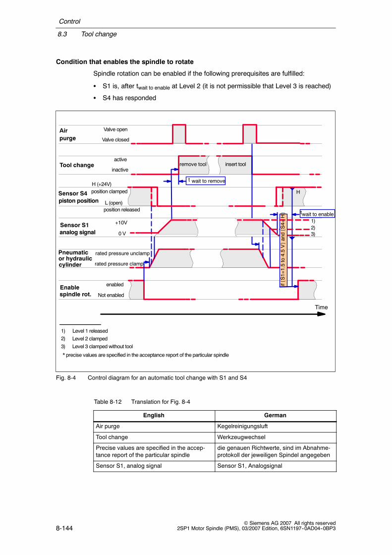
Control
8.3 Tool change
8-144© Siemens AG 2007 All rights reserved
2SP1 Motor Spindle (PMS), 03/2007 Edition, 6SN1197--0AD04--0BP3
Condition that enables the spindle to rotate
Spindle rotation can be enabled if the following prerequisites are fulfilled:
S S1 is, after twait to enable at Level 2 (it is not permissible that Level 3 is reached)
S S4 has responded
Time
Sensor S10 V
+10V
rated pressure clamp
rated pressure unclamp
Enablespindle rot. Not enabled
enabled
Tool changeinactive
activeremove tool insert tool
Sensor S4
L (open)
H (+24V)
Level 1 released
H
twait to enable
t wait to remove
Airpurge Valve closed
Valve open
piston position
Pneumaticor hydrauliccylinder
analog signal
position clamped
position released
Level 2 clampedLevel 3 clamped without tool
* precise values are specified in the acceptance report of the particular spindle
1)2)3)
1)2)
3)
iffS1=1.5to4.5VgandfS4=
Hg
Fig. 8-4 Control diagram for an automatic tool change with S1 and S4
Table 8-12 Translation for Fig. 8-4
English German
Air purge Kegelreinigungsluft
Tool change Werkzeugwechsel
Precise values are specified in the accep-tance report of the particular spindle
die genauen Richtwerte, sind im Abnahme-protokoll der jeweiligen Spindel angegeben
Sensor S1, analog signal Sensor S1, Analogsignal

Control
8.3 Tool change
8-145© Siemens AG 2007 All rights reserved2SP1 Motor Spindle (PMS), 03/2007 Edition, 6SN1197--0AD04--0BP3
Table 8-12 Translation for Fig. 8-4, continued
English German
Sensor S4, piston position Sensor S4, Lösekolben Position
Pneumatic or hydraulic cylinder Pneumatik- oder Hydraulikzylinder
Enable spindle rot. Freigabe ”Drehbewegung Spindel”
Valve open Ventil offen
Valve closed Ventil geschlossen
Active Aktiv
Inactive Inaktiv
Open Offen
Rated pressure release Nenndruck lösen
Rated pressure clamp Nenndruck spannen
No pressure Kein Druck
Enabled Freigabe
Not enabled keine Freigabe
If pressure > min rated pressure and ... Wenn Druck > min. Nenndruck und ...
Remove tool Werkzeug entfernen
Insert tool Werkzeug einsetzen
twait to remove twarten bis zum Entfernen
twait to enable twarten bis zur Freigabe
Time Zeit
Position clamped Position gespannt
position released Position gelöst

Control
8.3 Tool change
8-146© Siemens AG 2007 All rights reserved
2SP1 Motor Spindle (PMS), 03/2007 Edition, 6SN1197--0AD04--0BP3
8.3.2 Tool change sequence with standard clamping system and toolchange gripper
Table 8-13 Recommended sequence for a tool change with standard clamping system and tool changegripper
Step Description
1. Stop the spindle (0 speed) in the oriented tool change position
2. Shut down the internal tool cooling, open the bleed valve
3. Open the door of the automatic tool change system
4. Move the machine axes into the tool change position
5. Prepare the tool magazine for the tool change
6. Start the automatic tool change mechanism -- tool change gripper takes the tool in the toolmagazine and inserts the tool into the spindle.
7. Stop the automatic tool change mechanism
8. Activate the air purge
9. Release the tool by controlling the valve ”release tool”Check sensor signal S1 1) for state ”draw bar in release position”
10. Continue the automatic tool change mechanism -- tool removal, 180_-Rotate the toolchange gripper and insert the new tool into the spindle. Place the previously used tool intothe tool magazine. The tool change gripper still holds the tool into the spindle.
11. Shut off the air purge and close the bleed valve
12. Clamp the toolCheck the sensor signal S1 for state ”tool clamped”Check that the sensor S4 is at a ”high” signal (release piston at the back)
13. Move the tool change gripper into the park position. Exit the automatic tool changing mech-anism.
14. Start the spindle. Close the door of the automatic tool change system.
15. Move the axes into the machining position
1) Precise test values, refer to the acceptance report of the particular motor spindle

Control
8.3 Tool change
8-147© Siemens AG 2007 All rights reserved2SP1 Motor Spindle (PMS), 03/2007 Edition, 6SN1197--0AD04--0BP3
8.3.3 Tool change sequence with holding clamping system and toolchange gripper
Table 8-14 Recommended sequence for a tool change with holding clamping system and tool changegripper
Step Description
1. Stop the spindle (0 speed) in the oriented tool change position
2. Shut down the internal tool cooling, open the bleed valve
3. Release the tool in the spindle by controlling the valve ”release tool”.Check sensor signal S1 1) for state ”draw bar in the release position”The tool is still held by the collet.Caution: The tool weight should not exceed the permissible limits, otherwise the toolcan fall out of the tool holder.
4. Activate the air purge
5. Open the door of the automatic tool change system
6. Move the machine axes into the tool change position.Caution: If the acceleration or deceleration is too high than the tool can drop out ofthe tool holder.
7. Prepare the tool magazine for the tool change
8. Start the automatic tool change mechanism -- tool change gripper takes the tool in the toolmagazine and inserts the tool into the spindle.Tool removal (holding force of 270 N must be overcome).180_-rotation of the tool gripper and insert the new tool into the spindle. Place the pre-viously used tool into the tool magazine.
9. Move the tool change gripper into the park position. Exit the automatic tool changing mech-anism.
10. Shut off the air purge and close the bleed valve
11. Clamp the toolCheck the sensor signal S1 for state ”tool clamped”Check that the sensor S4 is at a ”high” signal (release piston at the back)
12. Start spindle. Close the door of the automatic tool change system.
13. Move the axes into the machining position
1) Precise test values, refer to the acceptance report of the particular motor spindle

Control
8.3 Tool change
8-148© Siemens AG 2007 All rights reserved
2SP1 Motor Spindle (PMS), 03/2007 Edition, 6SN1197--0AD04--0BP3
8.3.4 Manual tool change for 2SP125VV
With the basic equipping (with sensor S2 -- without S1 and S3), this version can beused for a manual tool change.
Notice
The appropriate operator actions must be applied to ensure that the appropriateclamping state has been reached before the spindle is allowed to rotate and beforea tool may be changed.
Caution
Jammed tools cannot be reliably detected using sensor S1.
If the spindle is operated without the optional sensor S1, then it is the responsibilityof the machinery construction company to detect the ”tool released” state.
If the spindle is operated without the optional sensor S3, then it is the responsibilityof the machinery construction company to detect the ”clamped without tool” state.
Note
It is advantageous if additional information is incorporated in the tool changecontrol sequence by using additional sensors.
The machinery construction company must provide any additional sensors.
The pressure at the release piston can also be incorporated in the tool changecontrol system.
Enable condition
Enable condition to initiate a tool change:
S The required pressure -- to release the tool -- must be available

Control
8.3 Tool change
8-149© Siemens AG 2007 All rights reserved2SP1 Motor Spindle (PMS), 03/2007 Edition, 6SN1197--0AD04--0BP3
Time
Pneumaticcylinder Rated pressure clamp
Rated pressure unclamp
Enablespindle rot. Not enabled
Enabled
Tool changeInactive
ActiveRemove tool Insert tool
Sensor S2L (open)
H (+24V)
H twait to enabletwait to remove
Airpurge Valve closed
Valve open
Ladditionalm
anual
releaseon
request
additionalm
anual
clam
pon
request
ifpressure>minrated
pressureandS2=L
ifpressure=0
and
S2=H
Fig. 8-5 Control diagram for a manual change with S2
Table 8-15 Translation for Fig. 8-5
English German
Air purge Kegelreinigungsluft
Additional manual release on request zusätzlich manuelles lösen
Additional manual clamp on request zusätzlich manuelles spannen
Tool change Werkzeugwechsel
Sensor S2 Sensor S2
Pneumatic cylinder Pneumatikzylinder
Enable spindle rot. Freigabe ”Drehbewegung Spindel”
Valve open Ventil offen
Valve closed Ventil geschlossen
Active Aktiv
Inactive Inaktiv
if pressure > min rated pressure andS2 = L
Wenn Druck > min. Nenndruck undS2 = L
if pressure = 0 and S2 = H Wenn Druck = 0 und S2 = H
Open Offen
Rated pressure release Nenndruck lösen
Rated pressure clamp Nenndruck spannen

Control
8.3 Tool change
8-150© Siemens AG 2007 All rights reserved
2SP1 Motor Spindle (PMS), 03/2007 Edition, 6SN1197--0AD04--0BP3
Table 8-15 Translation for Fig. 8-5, continued
English German
Enabled Freigabe
Not enabled keine Freigabe
Remove tool Werkzeug entfernen
Insert tool Werkzeug einsetzen
Twait to remove Twarten bis zum Entfernen
Twait to enable Twarten bis zur Freigabe
Time Zeit
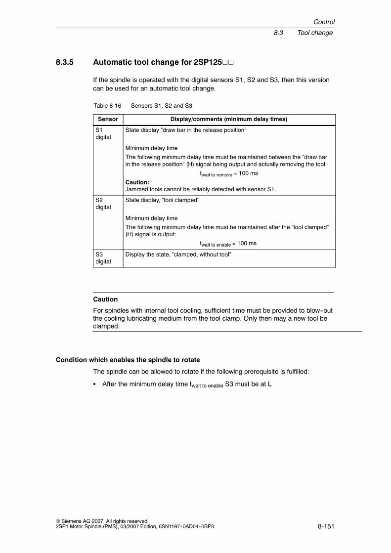
Control
8.3 Tool change
8-151© Siemens AG 2007 All rights reserved2SP1 Motor Spindle (PMS), 03/2007 Edition, 6SN1197--0AD04--0BP3
8.3.5 Automatic tool change for 2SP125VV
If the spindle is operated with the digital sensors S1, S2 and S3, then this versioncan be used for an automatic tool change.
Table 8-16 Sensors S1, S2 and S3
Sensor Display/comments (minimum delay times)
S1digital
State display ”draw bar in the release position”
Minimum delay time
The following minimum delay time must be maintained between the ”draw barin the release position” (H) signal being output and actually removing the tool:
twait to remove = 100 ms
Caution:Jammed tools cannot be reliably detected with sensor S1.
S2digital
State display, ”tool clamped”
Minimum delay time
The following minimum delay time must be maintained after the ”tool clamped”(H) signal is output:
twait to enable = 100 ms
S3digital
Display the state, ”clamped, without tool”
Caution
For spindles with internal tool cooling, sufficient time must be provided to blow--outthe cooling lubricating medium from the tool clamp. Only then may a new tool beclamped.
Condition which enables the spindle to rotate
The spindle can be allowed to rotate if the following prerequisite is fulfilled:
S After the minimum delay time twait to enable S3 must be at L

Control
8.3 Tool change
8-152© Siemens AG 2007 All rights reserved
2SP1 Motor Spindle (PMS), 03/2007 Edition, 6SN1197--0AD04--0BP3
Time
Sensor S1L (open)
H (+24V)
Pneumaticcylinder Rated pressure clamp
Rated pressure release
Enablespindle rot. Not enabled
Enabled
Tool changeInactive
ActiveRemove tool Insert tool
Sensor S2L (open)
H (+24V)
Sensor S3L (open)
H (+24V)
L
H
L
ifS1=L
andS2=HandS3=L
t wait to enable
t wait to remove
Airpurge Valve closed
Valve open
For internal tool cooling:
sufficient time for air purge is necessary toblowout the coolant from the clamping system
Fig. 8-6 Control diagram for an automatic tool change with S1, S2 and S3
Table 8-17 Translation for Fig. 8-6
English German
For internal tool cooling: sufficient time forair purge is necessary to blow out the cool-ant from the clamping system
Bei Werkzeug-Innenkühlung: AusreichendZeit vorsehen zum Ausblasen desKühlschmiermittels aus dem Werkzeug-spanner
Air purge Kegelreinigungsluft
Tool change Werkzeugwechsel
Sensor S1, Sensor S2, Sensor S3 Sensor S1, Sensor S2, Sensor S3
Pneumatic cylinder Pneumatikzylinder

Control
8.3 Tool change
8-153© Siemens AG 2007 All rights reserved2SP1 Motor Spindle (PMS), 03/2007 Edition, 6SN1197--0AD04--0BP3
Table 8-17 Translation for Fig. 8-6, continued
English German
Enable spindle rot. Freigabe ”Drebewegung Spindel”
Valve open Ventil offen
Valve closed Ventil geschlossen
Active Aktiv
Inactive Inaktiv
open, opened offen, geöffnet
Rated pressure unclamp Nenndruck lösen
Rated pressure clamp Nenndruck spannen
Enabled Freigabe
Not enabled keine Freigabe
Remove tool Werkzeug entfernen
Insert tool Werkzeug einsetzen
Twait to remove TWarten bis zum Entfernen
Twait to enable TWarten bis zur Freigabe
if S1=L and S2=H and S3=L wenn S1=L und S2=H und S3=L
Time Zeit
J

Control
8.3 Tool change
8-154© Siemens AG 2007 All rights reserved
2SP1 Motor Spindle (PMS), 03/2007 Edition, 6SN1197--0AD04--0BP3
Space for your notes

9-155© Siemens AG 2007 All rights reserved2SP1 Motor Spindle (PMS), 03/2007 Edition, 6SN1197--0AD04--0BP3
Order Designation
Structure of the order designation
The Order Number comprises a combination of digits and letters. It is sub--dividedinto three hyphenated blocks.
The spindle type is defined in the first block. Additional features are described inthe 2nd and 3rd blocks.
9

Order Designation
9-156© Siemens AG 2007 All rights reserved
2SP1 Motor Spindle (PMS), 03/2007 Edition, 6SN1197--0AD04--0BP3
Order designation for 2SP120j
Cooling
1 = Enclosed cooling jacked3 = Enclosed cooling jacket and internal cooling4 = Enclosed cooling jacket, with ring with 6 nozzles for external tool cooling5 = Enclosed cooling jacket, internal tool cooling and ring with 6 nozzles for external
tool cooling6 = Enclosed cooling jacket, with ring with 8xG1/4” for external tool cooling7 = Enclosed cooling jacket, internal tool cooling and ring with 8xG1/4” for external
tool cooling
Winding version
Order number: P 12 S . --2 0 . .1 H . .. -- . .
Encoder type
2SP1 motor spindle
Spindle length
Synchronous/induction 4-pole
2 = spindle length, short4 = spindle length, long
Spindle diameter
H = sin/cos 1 Vpp, 256 pulses/rev
1 = Synchronous
See Chapter ”Technical characteristic data”
Sensor systems
Power cables and connectors
Bearings
2 = 1.5 m power cable, signal connector for sensors6 = 1.5 m power cable and connector size 1.5, signal connector for sensors (only for 2SP1202)6 = 1.5 m power cable and connector size 3, signal connector for sensors (only for 2SP1204)
1 = Bearings for max. speed up to 15000 rpm2 = bearings for max. speed up to 18000 rpm
Tool interfaces
D = Tool interface HSK A63R = Tool interface HSK A63 type C, holding clamping set
20 = Spindle diameter 200 mm
Tool release and clamping device
2 = 2-channel technology, pneumatic3 = 2-channel technology, hydraulic
D = 3 digital sensors for the tool clamped state: ”Tool clamped”, ”draw bar in the release position”,and ”clamped without tool”; 1 digital sensor for position ”release piston”.
F = 1 analog sensor for tool clamped state: ”Tool clamped”, ”draw bar in the release position”,and ”clamped without tool”;1 digital sensor for position ”release piston”.
G = as for F + PT100 to monitor the bearing temperatureH = as D + PT100 to monitor the bearing temperature
Fig. 9-1 Order designation for 2SP120V
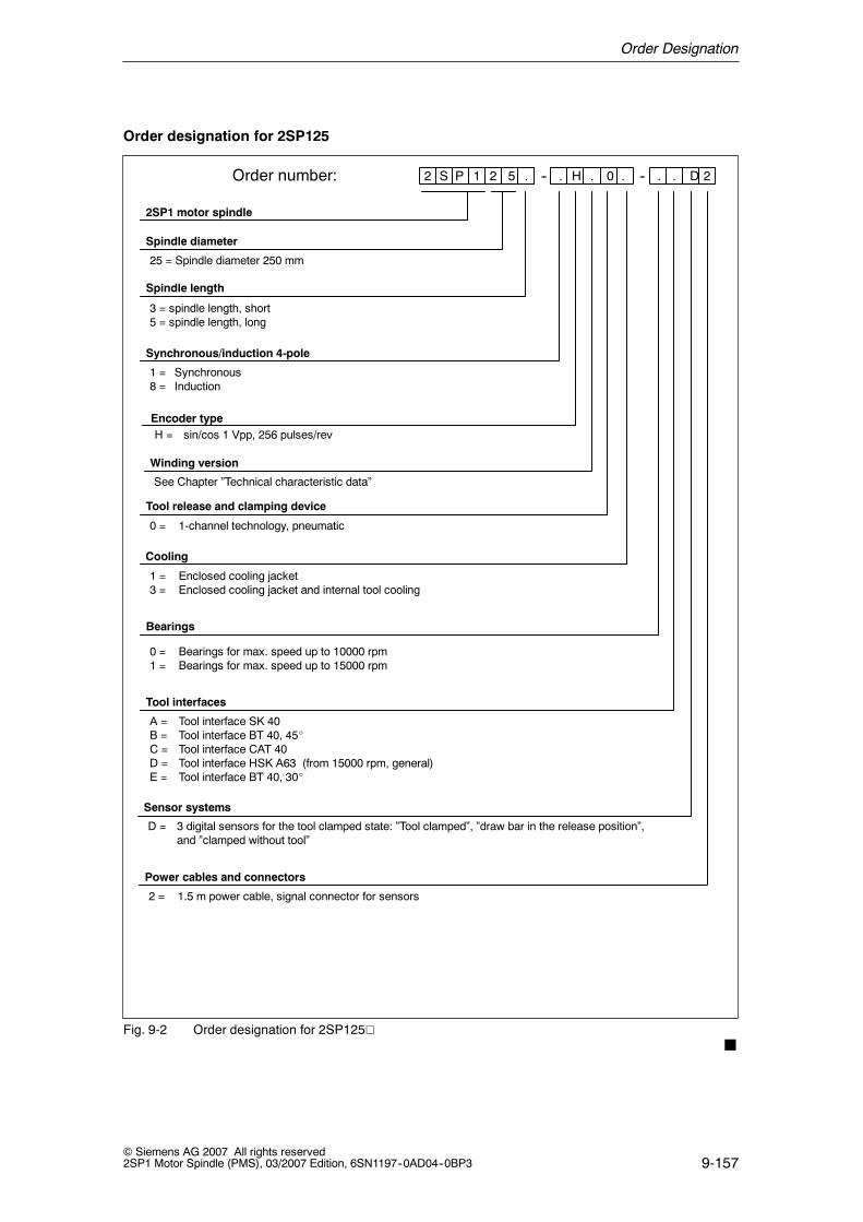
Order Designation
9-157© Siemens AG 2007 All rights reserved2SP1 Motor Spindle (PMS), 03/2007 Edition, 6SN1197--0AD04--0BP3
Order designation for 2SP125
Cooling
1 = Enclosed cooling jacket3 = Enclosed cooling jacket and internal tool cooling
Winding version
Order number: P 12 S . --2 5 . 0. H . .. -- D 2
Encoder type
2SP1 motor spindle
Spindle length
Synchronous/induction 4-pole
3 = spindle length, short5 = spindle length, long
Spindle diameter
H = sin/cos 1 Vpp, 256 pulses/rev
1 = Synchronous8 = Induction
See Chapter ”Technical characteristic data”
Sensor systems
Power cables and connectors
D = 3 digital sensors for the tool clamped state: ”Tool clamped”, ”draw bar in the release position”,and ”clamped without tool”
Bearings
2 = 1.5 m power cable, signal connector for sensors
0 = Bearings for max. speed up to 10000 rpm1 = Bearings for max. speed up to 15000 rpm
Tool interfaces
A = Tool interface SK 40B = Tool interface BT 40, 45_C = Tool interface CAT 40D = Tool interface HSK A63 (from 15000 rpm, general)E = Tool interface BT 40, 30_
25 = Spindle diameter 250 mm
Tool release and clamping device
0 = 1-channel technology, pneumatic
Fig. 9-2 Order designation for 2SP125VJ

Order Designation
9-158© Siemens AG 2007 All rights reserved
2SP1 Motor Spindle (PMS), 03/2007 Edition, 6SN1197--0AD04--0BP3
Space for your notes

10-159© Siemens AG 2007 All rights reserved2SP1 Motor Spindle (PMS), 03/2007 Edition, 6SN1197--0AD04--0BP3
Data Sheets
10.1 Technical characteristic data
Electrical power data
The values in Table 10-1 are only applicable in conjunction with Siemens systemcomponents -- SIMODRIVE 611 digital/universal.
Table 10-1 Electrical power data
Order No. PN
S1[kW]
MN
S1[Nm]
nN
[RPM]
IN
S1[A]
PN
S6-40%[kW]
MN
S6-40%[Nm]
PN
S1[kW]
MN
S1[Nm]
nN
[RPM]
IN
S1[A]
Imax1)
[A]
nmax
[RPM]
Star configuration Delta configuration
Synchronous
2SP1202-1HAjj-1DF 12.0 42 2700 30 12.0 55 ------ ------ ------ ------ 60 15000
2SP1202-1HBjj-2DF 15.5 42 3500 42 15.5 55 ------ ------ ------ ------ 84 18000
2SP1204-1HAjj-1DF 26.4 84 3000 60 26.4 110 ------ ------ ------ ------ 120 15000
2SP1204-1HBjj-2DF 35.0 78 4300 79 35.0 110 ------ ------ ------ ------ 160 18000
Induction
2SP1253-8HA0j-0jj 13.2 70 1800 28 18.9 100 13.2 32 4000 29 51 10000
2SP1253-8HA0j-1Dj 13.2 70 1800 28 18.9 100 13.2 32 4000 29 51 15000
2SP1255-8HA0j-0jj 11.7 140 800 30 16.7 200 11.7 62 1800 29 51 10000
2SP1255-8HA0j-1Dj 11.7 140 800 30 16.7 200 11.7 62 1800 29 51 15000
Synchronous
2SP1253-1HA0j-0jj 26.0 100 2500 53 29.0 130 ------ ------ ------ ------ 106 10000
Reduced motor data 2) 22.5 80 2700 45 ------ ------ ------ ------ ------ ------ ------ ------
2SP1253-1HB0j-1Dj 35.0 100 3300 68 38.0 130 ------ ------ ------ ------ 136 15000
Reduced motor data 2) 30 80 3600 60 ------ ------ ------ ------ ------ ------ ------ ------
2SP1255-1HA0j-0jj 46.3 170 2600 95 55.0 236 ------ ------ ------ ------ 170 10000
Reduced motor data 2) 40 150 2560 85 ------ ------ ------ ------ ------ ------ ------ ------
2SP1255-1HB0j-1Dj 53.4 170 3000 120 64.0 236 ------ ------ ------ ------ 240 15000
Reduced motor data 2) 40 150 3000 105 ------ ------ ------ ------ ------ ------ ------ ------
1) It is not permissible that the maximum current is exceeded due to danger of de--magnetization2) The values apply for reduced motor data that match the next smaller power module
10

Data Sheets
10.1 Technical characteristic data
10-160© Siemens AG 2007 All rights reserved
2SP1 Motor Spindle (PMS), 03/2007 Edition, 6SN1197--0AD04--0BP3
Supply data
Table 10-2 Supply data
Order No. Motortype
Max.speed
nmax [RPM]
Requiredcooling
PcoolN [kW] at
Coolingmediumflow rate
Coolingmediumpressuredrop 1)
Max. per-missiblecoolingmedium
nN nmax V [l/min]dropnp [hpa]
mediumpressurep [bar]
2SP1202-1jAjj-0 Synch. 15000 2.0 2.0 10 0.5 5.0
2SP1202-1jBjj-1 Synch. 18000 2.0 2.6 10 0.5 5.0
2SP1204-1jAjj-0 Synch. 15000 3.6 4.2 10 1.0 5.0
2SP1204-1jBjj-1 Synch. 18000 3.6 5.0 10 1.0 5.0
2SP1253-8jAjj-0 Induct. 10000 2.8 2.8 10 0.75 5.0
2SP1253-8jAjj-1 Induct. 15000 2.8 2.8 10 0.75 5.0
2SP1255-8jAjj-0 Induct. 10000 4.3 4.3 10 1.0 5.0
2SP1255-8jAjj-1 Induct. 15000 4.3 4.3 10 1.0 5.0
2SP1253-1jAjj-0 Synch. 10000 2.1 3.0 10 0.75 5.0
2SP1253-1jBjj-1 Synch. 15000 2.1 4.5 10 0.75 5.0
2SP1255-1jAjj-0 Synch. 10000 3.5 4.5 10 1.0 5.0
2SP1255-1jBjj-1 Synch. 15000 3.5 6.0 10 1.0 5.0
1) At the specified flow quantity

Data Sheets
10.1 Technical characteristic data
10-161© Siemens AG 2007 All rights reserved2SP1 Motor Spindle (PMS), 03/2007 Edition, 6SN1197--0AD04--0BP3
Power data at the tool holder
Table 10-3 Power data at the tool holder
Order No. Radialeccentricity 1)
[ ]
Pull-force
2)
Typical time 3) [ms]to
Minimumaccel. time to
6) [ ][µm] 2)
[kN]Clamp tool
4)Releasetool 5)
nmax 6) [sec]
2SP1202-1jA0j-1 15 18 320 350 1.5
2SP1202-1jA1j-1 15 18 180 200 1.5
2SP1202-1jB0j-2 15 18 320 350 1.7
2SP1202-1jB1j-2 15 18 180 200 1.7
2SP1204-1jA0j-1 15 18 320 350 1.0
2SP1204-1jA1j-1 15 18 180 200 1.0
2SP1204-1jB0j-2 15 18 320 350 1.2
2SP1204-1jB1j-2 15 18 180 200 1.2
2SP1253-8jAjj-0 15 8 270 230 1.30
2SP1253-8jAjj-1 15 18 180 300 3.50
2SP1255-8jAjj-0 15 8 270 230 2.25
2SP1255-8jAjj-1 15 18 180 300 6.75
2SP1253-1jAjj-0 15 8 270 230 0.8
2SP1253-1jBjj-1 15 18 180 300 1.25
2SP1255-1jAjj-0 15 8 270 230 0.6
2SP1255-1jBjj-1 15 18 180 300 1.1
1) Radial eccentricity measured at the plug gauge 280 mm from the spindle nose.2) Nominal value, dependent on the tool interface (SK40/HSK A63)
Tolerance values for SK40: +1.6 kN, --0.8 kNTolerance values for HSK A63: +5.4 kN, --1.9 kN
3) Characteristic values/parameters are dependent on the release pressure, flow rate and for the pneumaticrelease unit, from the number connections used;Hydraulic release unit:The specified values are reached for an 80 bar release pressure with a sufficient flow rate.Pneumatic release unit:The specified values are reached for a release pressure of 6 bar, sufficient flow rate and 2 connections.
4) Time between the valve switching up to the ”tool clamped” sensor signal.5) Time between the valve switching up to the ”draw bar in release position” sensor signal.6) For an adequately dimensioned power module.
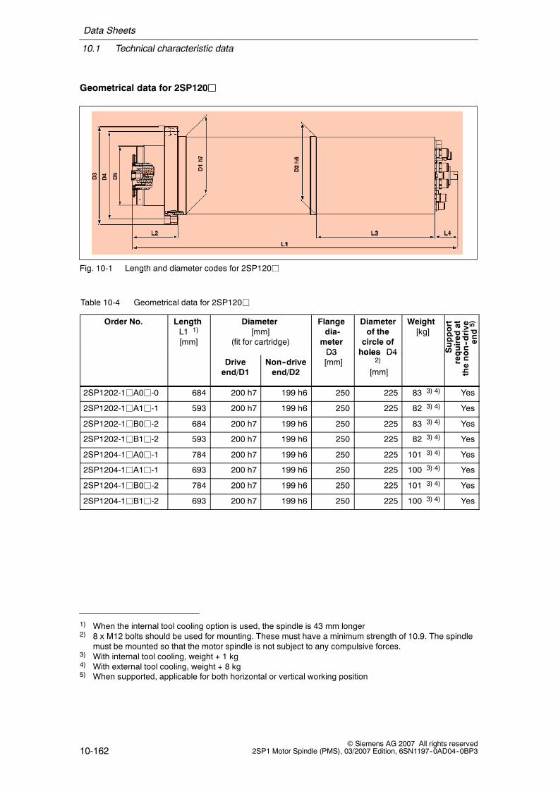
Data Sheets
10.1 Technical characteristic data
10-162© Siemens AG 2007 All rights reserved
2SP1 Motor Spindle (PMS), 03/2007 Edition, 6SN1197--0AD04--0BP3
Geometrical data for 2SP120j
Fig. 10-1 Length and diameter codes for 2SP120j
Table 10-4 Geometrical data for 2SP120j
Order No. LengthL1 1)
[mm]
Diameter[mm]
(fit for cartridge)
Flangedia-meterD3
Diameterof thecircle ofholes D4
Weight[kg]
Support
quired
aton--drive
end5)
Driveend/D1
Non--driveend/D2
D3[mm]
holes D42)
[mm]
Sreq
theno
2SP1202-1jA0j-0 684 200 h7 199 h6 250 225 83 3) 4) Yes
2SP1202-1jA1j-1 593 200 h7 199 h6 250 225 82 3) 4) Yes
2SP1202-1jB0j-2 684 200 h7 199 h6 250 225 83 3) 4) Yes
2SP1202-1jB1j-2 593 200 h7 199 h6 250 225 82 3) 4) Yes
2SP1204-1jA0j-1 784 200 h7 199 h6 250 225 101 3) 4) Yes
2SP1204-1jA1j-1 693 200 h7 199 h6 250 225 100 3) 4) Yes
2SP1204-1jB0j-2 784 200 h7 199 h6 250 225 101 3) 4) Yes
2SP1204-1jB1j-2 693 200 h7 199 h6 250 225 100 3) 4) Yes
1) When the internal tool cooling option is used, the spindle is 43 mm longer2) 8 x M12 bolts should be used for mounting. These must have a minimum strength of 10.9. The spindle
must be mounted so that the motor spindle is not subject to any compulsive forces.3) With internal tool cooling, weight + 1 kg4) With external tool cooling, weight + 8 kg5) When supported, applicable for both horizontal or vertical working position

Data Sheets
10.1 Technical characteristic data
10-163© Siemens AG 2007 All rights reserved2SP1 Motor Spindle (PMS), 03/2007 Edition, 6SN1197--0AD04--0BP3
Geometrical data for 2SP125j
Fig. 10-2 Length and diameter codes for 2SP125j
Table 10-5 Geometrical data for 2SP125j
Order No. LengthL1 1)
[mm]
Diameter[mm]
(fit for cartridge)
Flangedia-meterD3
Diameterof thecircle ofholes D4
Weight[kg]
Support
edatthe
drive
end 5)
Driveend/D1
Non--driveend/D2
D3[mm]
holes D42)
[mm]
Srequire
non--dr
2SP1253-8jAjj-0 776 250 h7 237 h6 310 275 130 3) No
2SP1253-8jAjj-1 770 250 h7 237 h6 310 275 130 3) No
2SP1255-8jAjj-0 876 250 h7 237 h6 310 275 165 3) No
2SP1255-8jAjj-1 870 250 h7 237 h6 310 275 165 3) Yes
2SP1253-1jAjj-0 776 250 h7 237 h6 310 275 130 3) No
2SP1253-1jBjj-0 770 250 h7 237 h6 310 275 130 3) No
2SP1255-1jAjj-0 876 250 h7 237 h6 310 275 165 3) No
2SP1255-1jBjj-1 870 250 h7 237 h6 310 275 165 3) Yes
1) When the internal tool cooling option is used, the spindle is 43 mm longer2) 8 x M12 bolts should be used for mounting. These must have a minimum strength of 10.9. The spindle
must be mounted so that the motor spindle is not subject to any compulsive forces.3) With internal tool cooling, weight + 1 kg5) When supported, applicable for both horizontal or vertical working position

Data Sheets
10.2 P/n and M/n diagrams
10-164© Siemens AG 2007 All rights reserved
2SP1 Motor Spindle (PMS), 03/2007 Edition, 6SN1197--0AD04--0BP3
10.2 P/n and M/n diagrams
The diagrams apply for a 600 V DC link voltage
10.2.1 2SP120V synchronous motor
Table 10-6 Motor spindle 2SP1202--1VAVV-1
Motor spindle 2SP1202 (only star circuit configuration)
Circuit type Rated power
PN [kW]
Rated speed
nN [RPM]
Rated torque
MN [Nm]
Rated current
IN [A]
Max.speednmax[RPM]
Moment ofinertia
J[kgm2]
12.0 2700 42 30 15000 0.015
------ ------ ------ ------ ------ ------
P[kW]
n [RPM]0
2
4
6
8
10
12
14
0 2500 5000 7500 10000 12500 15000
Plimit
S6--25% (52A)
S6--40% (43A)
S6--60% (36A)
S1 (30A)
M[Nm]
0
10
20
30
40
50
60
70
0 2500 5000 7500 10000 12500 15000
Mlimit
S6--25% (52A)
S6--40% (43A)
S6--60% (36A)
S1 (30A)
n [RPM]
The data for duty type S6 are valid for a 2 min. duty cycle.

Data Sheets
10.2 P/n and M/n diagrams
10-165© Siemens AG 2007 All rights reserved2SP1 Motor Spindle (PMS), 03/2007 Edition, 6SN1197--0AD04--0BP3
Table 10-7 Motor spindle 2SP1202--1VBVV-2
Motor spindle 2SP1202 (only star circuit configuration)
Circuit type Rated power
PN [kW]
Rated speed
nN [RPM]
Rated torque
MN [Nm]
Rated current
IN [A]
Max.speednmax[RPM]
Moment ofinertia
J[kgm2]
15.5 3500 42 42 18000 0.015
------ ------ ------ ------ ------ ------
P[kW]
0
2
4
6
8
10
12
14
16
18
0 2000 4000 6000 8000 10000 12000 14000 16000 18000
Plimit
S6--25% (76A)
S6--40% (60A)
S6--60% (52A)
S1 (42A)
n [RPM]
M[Nm]
0
10
20
30
40
50
60
70
0 2000 4000 6000 8000 10000 12000 14000 16000 18000
Mlimit
S6--25% (76A)
S6--40% (60A)
S6--60% (52A)
S1 (42A)
n [RPM]
The data for duty type S6 are valid for a 2 min. duty cycle.

Data Sheets
10.2 P/n and M/n diagrams
10-166© Siemens AG 2007 All rights reserved
2SP1 Motor Spindle (PMS), 03/2007 Edition, 6SN1197--0AD04--0BP3
Table 10-8 Motor spindle 2SP1204--1VAVV-1
Motor spindle 2SP1204 (only star circuit configuration)
Circuit type Rated power
PN [kW]
Rated speed
nN [RPM]
Rated torque
MN [Nm]
Rated current
IN [A]
Max.speednmax[RPM]
Moment ofinertia
J[kgm2]
26.4 3000 84 60 15000 0.023
------ ------ ------ ------ ------ ------
P[kW]
0
5
10
15
20
25
30
0 2500 5000 7500 10000 12500 15000
Plimit
S6--25% (105A)
S6--40% (85A)
S6--60% (72A)
S1 (60A)
n [RPM]
M[Nm]
0
20
40
60
80
100
120
140
0 2500 5000 7500 10000 12500 15000
Mlimit
S6--25% (105A)
S6--40% (85A)
S6--60% (72A)
S1 (60A)
n [RPM]
The data for duty type S6 are valid for a 2 min. duty cycle.
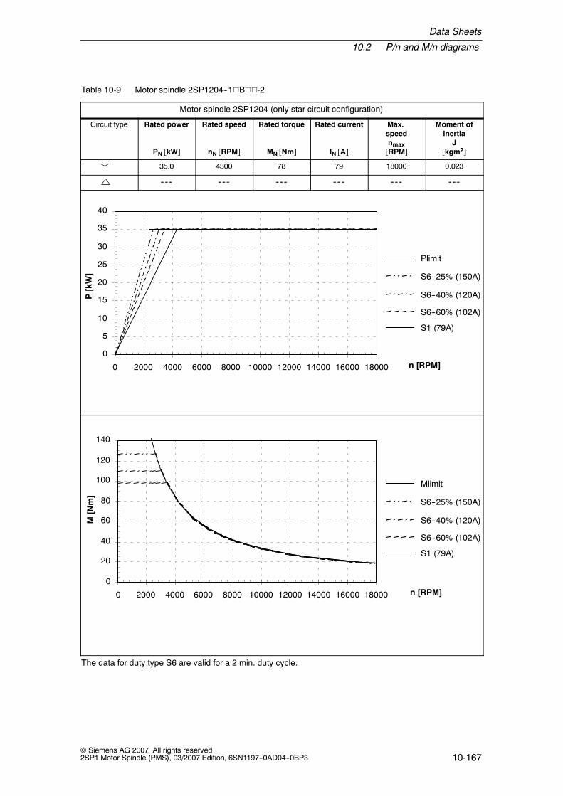
Data Sheets
10.2 P/n and M/n diagrams
10-167© Siemens AG 2007 All rights reserved2SP1 Motor Spindle (PMS), 03/2007 Edition, 6SN1197--0AD04--0BP3
Table 10-9 Motor spindle 2SP1204--1VBVV-2
Motor spindle 2SP1204 (only star circuit configuration)
Circuit type Rated power
PN [kW]
Rated speed
nN [RPM]
Rated torque
MN [Nm]
Rated current
IN [A]
Max.speednmax[RPM]
Moment ofinertia
J[kgm2]
35.0 4300 78 79 18000 0.023
------ ------ ------ ------ ------ ------
P[kW]
0
5
10
15
20
25
30
35
40
0 2000 4000 6000 8000 10000 12000 14000 16000 18000
Plimit
S6--25% (150A)
S6--40% (120A)
S6--60% (102A)
S1 (79A)
n [RPM]
M[Nm]
0
20
40
60
80
100
120
140
0 2000 4000 6000 8000 10000 12000 14000 16000 18000
Mlimit
S6--25% (150A)
S6--40% (120A)
S6--60% (102A)
S1 (79A)
n [RPM]
The data for duty type S6 are valid for a 2 min. duty cycle.

Data Sheets
10.2 P/n and M/n diagrams
10-168© Siemens AG 2007 All rights reserved
2SP1 Motor Spindle (PMS), 03/2007 Edition, 6SN1197--0AD04--0BP3
10.2.2 2SP125V synchronous motor
Table 10-10 Motor spindle 2SP1253--1VAVV-0
Motor spindle 2SP1253--1VAVV-0 (only star circuit configuration)
Circuit type Rated power
PN [kW]
Rated speed
nN [RPM]
Rated torque
MN [Nm]
Rated current
IN [A]
Max.speednmax[RPM]
Moment ofinertia
J[kgm2]
26 2500 100 53 10000 0.037
------ ------ ------ ------ ------ ------
P[kW]
0
5
10
15
20
25
30
35
0 2000 4000 6000 8000 10000
Plimit
S6--25% (93A)
S6--40% (75A)
S6--60% (64A)
S1 (53A)
S1 (45A)
n [RPM]
M[Nm]
0
20
40
60
80
100
120
140
160
0 2000 4000 6000 8000 10000
Mlimit
S6--25% (93A)
S6--40% (75A)
S6--60% (64A)
S1 (53A)
S1 (45A)
n [RPM]
The data for duty type S6 are valid for a 2 min. duty cycle.

Data Sheets
10.2 P/n and M/n diagrams
10-169© Siemens AG 2007 All rights reserved2SP1 Motor Spindle (PMS), 03/2007 Edition, 6SN1197--0AD04--0BP3
Table 10-11 Motor spindle 2SP1253--1VBVV-0
Motor spindle 2SP1253--1VBVV-0 (only star circuit configuration)
Circuit type Rated power
PN [kW]
Rated speed
nN [RPM]
Rated torque
MN [Nm]
Rated current
IN [A]
Max.speednmax[RPM]
Moment ofinertia
J[kgm2]
35 3300 100 68 15000 0.037
------ ------ ------ ------ ------ ------
P[kW]
0
5
10
15
20
25
30
35
40
0 3000 6000 9000 12000 15000
Plimit
S6--25% (121A)
S6--40% (98A)
S6--60% (83A)
S1 (68A)
S1 (60A)
n [RPM]
M[Nm]
0
20
40
60
80
100
120
140
160
0 3000 6000 9000 12000 15000
Plimit
S6--25% (121A)
S6--40% (98A)
S6--60% (83A)
S1 (68A)
S1 (60A)
n [RPM]
The data for duty type S6 are valid for a 2 min. duty cycle.
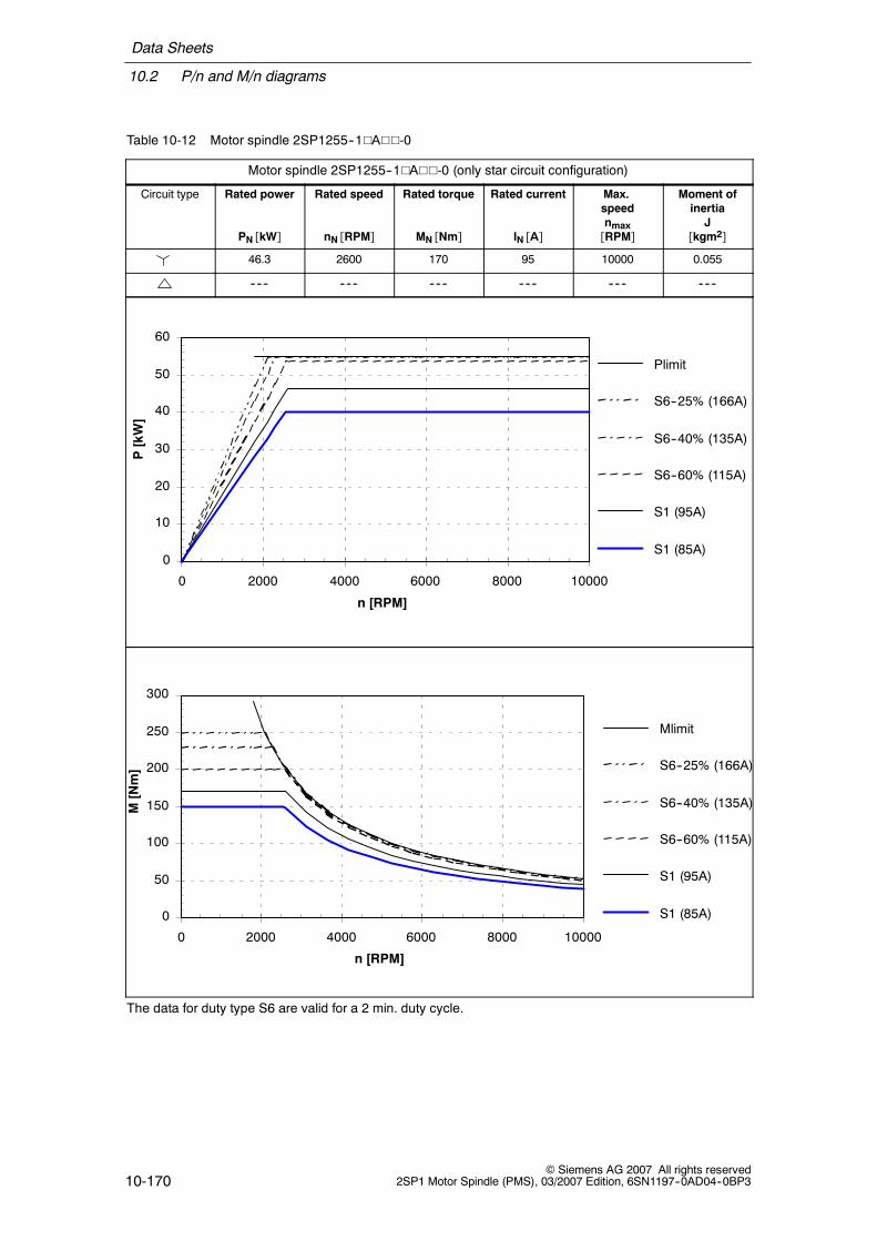
Data Sheets
10.2 P/n and M/n diagrams
10-170© Siemens AG 2007 All rights reserved
2SP1 Motor Spindle (PMS), 03/2007 Edition, 6SN1197--0AD04--0BP3
Table 10-12 Motor spindle 2SP1255--1VAVV-0
Motor spindle 2SP1255--1VAVV-0 (only star circuit configuration)
Circuit type Rated power
PN [kW]
Rated speed
nN [RPM]
Rated torque
MN [Nm]
Rated current
IN [A]
Max.speednmax[RPM]
Moment ofinertia
J[kgm2]
46.3 2600 170 95 10000 0.055
------ ------ ------ ------ ------ ------
P[kW]
Plimit
S6--25% (166A)
S6--40% (135A)
S6--60% (115A)
S1 (95A)
S1 (85A)0
10
20
30
40
50
60
0 2000 4000 6000 8000 10000
n [RPM]
M[Nm]
Mlimit
S6--25% (166A)
S6--40% (135A)
S6--60% (115A)
S1 (95A)
S1 (85A)0
50
100
150
200
250
300
0 2000 4000 6000 8000 10000
n [RPM]
The data for duty type S6 are valid for a 2 min. duty cycle.

Data Sheets
10.2 P/n and M/n diagrams
10-171© Siemens AG 2007 All rights reserved2SP1 Motor Spindle (PMS), 03/2007 Edition, 6SN1197--0AD04--0BP3
Table 10-13 Motor spindle 2SP1255--1VBVV-1
Motor spindle 2SP1255--1VBVV-1 (only star circuit configuration)
Circuit type Rated power
PN [kW]
Rated speed
nN [RPM]
Rated torque
MN [Nm]
Rated current
IN [A]
Max.speednmax[RPM]
Moment ofinertia
J[kgm2]
53.4 3000 170 120 15000 0.055
------ ------ ------ ------ ------ ------
P[kW]
0
10
20
30
40
50
60
70
0 3000 6000 9000 12000 15000
Plimit
S6--25% (221A)
S6--40% (180A)
S6--60% (148A)
S1 (120A)
S1 (105A)
n [RPM]
M[Nm]
0
50
100
150
200
250
300
0 2000 4000 6000 8000 10000 12000 14000 16000
Mlimit
S6--25% (221A)
S6--40% (180A)
S6--60% (148A)
S1 (120A)
S1 (105A)
n [RPM]
The data for duty type S6 are valid for a 2 min. duty cycle.

Data Sheets
10.2 P/n and M/n diagrams
10-172© Siemens AG 2007 All rights reserved
2SP1 Motor Spindle (PMS), 03/2007 Edition, 6SN1197--0AD04--0BP3
10.2.3 2SP125V induction motor
Table 10-14 Motor spindle 2SP1253-8VAVV-0
Motor spindle 2SP1253--8VAVV-0
Circuit type Rated power
PN [kW]
Rated speed
nN [RPM]
Rated torque
MN [Nm]
Rated current
IN [A]
Max.speednmax[RPM]
Moment ofinertia
J[kgm2]
13.2 1800 70 28 10000 0.037
13.2 4000 32 29 10000 0.037
0
2
4
6
8
10
12
14
16
18
20
22
24
0 1000 2000 3000 4000 5000 6000 7000 8000 9000 10000
P[kW]
Limiting power --
Limiting power -- Y
S6--40%--Y S6--40%--
S1--S1--Y
100 Nm
70 Nm
n [RPM]
M[Nm]
0
10
20
30
40
50
60
70
80
90
100
110
120
0 1000 2000 3000 4000 5000 6000 7000 8000 9000 10000
Limiting torque --
S6--40%--
S1--
Limiting torque -- YS6--40%--Y
S1--Y
n [RPM]
The data for duty type S6 are valid for a 2 min. duty cycle.

Data Sheets
10.2 P/n and M/n diagrams
10-173© Siemens AG 2007 All rights reserved2SP1 Motor Spindle (PMS), 03/2007 Edition, 6SN1197--0AD04--0BP3
Table 10-15 Motor spindle 2SP1253--8VAVV-1
Motor spindle 2SP1253--8VAVV-1
Circuit type Rated power
PN [kW]
Rated speed
nN [RPM]
Rated torque
MN [Nm]
Rated current
IN [A]
Max.speednmax[RPM]
Moment ofinertia
J[kgm2]
13.2 1800 70 28 15000 0.037
13.2 4000 32 29 15000 0.037
0
2
4
6
8
10
12
14
16
18
20
22
24
0 1000 2000 3000 4000 5000 6000 7000 8000 9000 10000 11000 12000 13000 14000 15000
P[kW]
n [RPM]
Limiting power --
Limiting power -- Y
S6--40%--S6--40%--Y
S1--
100 Nm
70 Nm
0
10
20
30
40
50
60
70
80
90
100
110
120
0 1000 2000 3000 4000 5000 6000 7000 8000 9000 10000 11000 12000 13000 14000 15000
M[Nm]
Limiting torque --
Limiting torque -- Y
S6--40%--Y
S6--40%--
S1--
S1--Y
n [RPM]
The data for duty type S6 are valid for a 2 min. duty cycle.

Data Sheets
10.2 P/n and M/n diagrams
10-174© Siemens AG 2007 All rights reserved
2SP1 Motor Spindle (PMS), 03/2007 Edition, 6SN1197--0AD04--0BP3
Table 10-16 Motor spindle 2SP1255--8VAVV-0
Motor spindle 2SP1255--8VAVV-0
Circuit type Rated power
PN [kW]
Rated speed
nN [RPM]
Rated torque
MN [Nm]
Rated current
IN [A]
Max.speednmax[RPM]
Moment ofinertia
J[kgm2]
11.7 800 140 30 10000 0.055
11.7 1800 62 29 10000 0.055
P[kW]
0
2
4
6
8
10
12
14
16
18
20
22
24
0 1000 2000 3000 4000 5000 6000 7000 8000 9000 10000
Limiting power --
Limiting power -- Y
S6--40%--Y S6--40%--
S1--S1--Y
200 Nm
140 Nm
n [RPM]
M[Nm]
0
20
40
60
80
100
120
140
160
180
200
0 1000 2000 3000 4000 5000 6000 7000 8000 9000 10000
Limiting torque --
S6--40%--
S1--
Limiting torque -- Y
S6--40%--Y
S1--Y
n [RPM]
The data for duty type S6 are valid for a 2 min. duty cycle.

Data Sheets
10.2 P/n and M/n diagrams
10-175© Siemens AG 2007 All rights reserved2SP1 Motor Spindle (PMS), 03/2007 Edition, 6SN1197--0AD04--0BP3
Table 10-17 Motor spindle 2SP1255--8VAVV-1
Motor spindle 2SP1255--8VAVV-1
Circuit type Rated power
PN [kW]
Rated speed
nN [RPM]
Rated torque
MN [Nm]
Rated current
IN [A]
Max.speednmax[RPM]
Moment ofinertia
J[kgm2]
11.7 800 140 30 15000 0.055
11.7 1800 62 29 15000 0.055
0
2
4
6
8
10
12
14
16
18
20
22
24
0 1000 2000 3000 4000 5000 6000 7000 8000 9000 10000 11000 12000 13000 14000 15000
P[kW]
Limiting power --
Limiting power -- Y
S6--40%--S6--40%--Y
S1--S1--Y
200 Nm
140 Nm
n [RPM]
0
20
40
60
80
100
120
140
160
180
200
0 1500 3000 4500 6000 7500 9000 10500 12000 13500 15000
M[Nm]
Limiting torque --
S6--40%--
S1--
Limiting torque -- Y
S6--40%--Y
S1--Y
n [RPM]
The data for duty type S6 are valid for a 2 min. duty cycle.

Data Sheets
10.3 Dimension drawings
10-176© Siemens AG 2007 All rights reserved
2SP1 Motor Spindle (PMS), 03/2007 Edition, 6SN1197--0AD04--0BP3
10.3 Dimension drawings
Note
Siemens AG reserves the right to change the motor dimensions, as part of designimprovements, without prior notification. The dimension drawings, provided in thisdocumentation, can go out--of--date.
Current dimension drawings can be requested at no charge from your localSiemens office.
Table 10-18 Dimension table for Fig. 10-3
MLFB Speed[RPM]
Motor Release unit Mom. ofinertia[kgm2]
A[mm]
A*[mm]
B[mm]
Powerconnector,optional
2SP1202--1HA3x--1xx2 15000 1FE082--4WP51 hydraulically 0.015 617 572 236 Size 1.5
2SP1202--1HA2x--1xx2 15000 1FE082--4WP51 pneumatically 0.015 735 692 236 Size 1.5
2SP1202--1HB3x--2xx2 18000 1FE082--4WN51 hydraulically 0.015 617 572 236 Size 1.5
2SP1202--1HA3x--2xx2 18000 1FE082--4WN51 pneumatically 0.015 735 692 236 Size 1.5
2SP1204--1HA3x--1xx2 15000 1FE084--4WT51 hydraulically 0.023 717 672 336 Size 3
2SP1204--1HA2x--1xx2 15000 1FE084--4WT51 pneumatically 0.023 835 792 336 Size 3
2SP1204--1HB3x--2xx2 18000 1FE082--4WP51 hydraulically 0.023 717 672 336 Size 3
2SP1204--1HB2x--2xx2 18000 1FE082--4WP51 pneumatically 0.023 835 792 336 Size 3
Dimension A* without rotary gland

Data Sheets
10.3 Dimension drawings
10-177© Siemens AG 2007 All rights reserved2SP1 Motor Spindle (PMS), 03/2007 Edition, 6SN1197--0AD04--0BP3
Fig. 10-3 Spindle 2SP120V--1

Data Sheets
10.3 Dimension drawings
10-178© Siemens AG 2007 All rights reserved
2SP1 Motor Spindle (PMS), 03/2007 Edition, 6SN1197--0AD04--0BP3
Fig. 10-4 Spindle 2SP120V--1, spindle nose and spindle connections

Data Sheets
10.3 Dimension drawings
10-179© Siemens AG 2007 All rights reserved2SP1 Motor Spindle (PMS), 03/2007 Edition, 6SN1197--0AD04--0BP3
Fig. 10-5 Connection designations

Data Sheets
10.3 Dimension drawings
10-180© Siemens AG 2007 All rights reserved
2SP1 Motor Spindle (PMS), 03/2007 Edition, 6SN1197--0AD04--0BP3
2SP125V
-1VV-0
synchronous
SK40/HSKA63,pneu.rls.unit
Fig. 10-6 Dimension drawing, spindles 2SP125V--1VV0 (pneumatic release unit)

Data Sheets
10.3 Dimension drawings
10-181© Siemens AG 2007 All rights reserved2SP1 Motor Spindle (PMS), 03/2007 Edition, 6SN1197--0AD04--0BP3
2SP125V
-8VV-0
induction
SK40/HSKA63,pneu.rls.unit
Fig. 10-7 Dimension drawing, spindles 2SP125V--8VV0 (pneumatic release unit)
J

Data Sheets
10.3 Dimension drawings
10-182© Siemens AG 2007 All rights reserved
2SP1 Motor Spindle (PMS), 03/2007 Edition, 6SN1197--0AD04--0BP3
Space for your notes

A-183© Siemens AG 2007 All rights reserved2SP1 Motor Spindle (PMS), 03/2007 Edition, 6SN1197--0AD04--0BP3
References
A list of documents, updated on a monthly basis is available in the Internet for theavailable languages under:http://www.siemens.com/motioncontrolthrough ”Support”, ”Technical Documentation”, ”Overview of Publications”
General Documentation
/BU/ Catalog NC 60
Automation Systems for Machine Tools
Manufacturer/Service Documentation
/PJM/ Configuration Manual, Synchronous Motors
SIMODRIVE 611, MASTERDRIVES MCGeneral Section, 1FT5, 1FT6, 1FK6, 1FK7
/PJAL/ Configuration Manual, Synchronous Motors
SIMODRIVE 611, MASTERDRIVES MCGeneral Section for Synchronous Motors
/PFK7/ Configuration Manual, Synchronous Motors
SIMODRIVE 611, MASTERDRIVES MCSynchronous Motors 1FK7
/PFK6/ Configuration Manual, Synchronous Motors
SIMODRIVE 611, MASTERDRIVES MCSynchronous Motors 1FK6
/PFT5/ Configuration Manual, Synchronous Motors
SIMODRIVESynchronous Motors 1FT5

References
A-184© Siemens AG 2007 All rights reserved
2SP1 Motor Spindle (PMS), 03/2007 Edition, 6SN1197--0AD04--0BP3
/PFT6/ Configuration Manual, Synchronous Motors
SIMODRIVE 611, MASTERDRIVES MCSynchronous Motors 1FT6
/ASAL/ Configuration Manual, Induction Motors
SIMODRIVEGeneral Section for Induction Motors for Main Spindle Drives
/APH2/ Configuration Manual, Induction Motors
SIMODRIVEInduction Motors for Main Spindle Drives 1PH2
/APH4/ Configuration Manual, Induction Motors
SIMODRIVEInduction Motors for Main Spindle Drives 1PH4
/APH7S/ Configuration Manual, Induction Motors
SIMODRIVEInduction Motors for Main Spindle Drives 1PH7
/APH7M/ Configuration Manual, Induction Motors
MASTERDRIVES MC/VCInduction Motors for Main Spindle Drives 1PH7
/PPM/ Configuration Manual, Hollow Shaft Motors
SIMODRIVEHollow Shaft Motors for Main Spindle Drives 1PM6 and 1PM4
/PJFE/ Configuration Manual, Synchronous Built--in Motors
SIMODRIVEThree--Phase Motors for Main Spindle DrivesSynchronous Built--in Motors 1FE1
/PFU/ Configuration Manual, Synchronous Motors
SINAMICS, SIMODRIVE, MASTERDRIVESSIEMOSYN Motors 1FU8

References
A-185© Siemens AG 2007 All rights reserved2SP1 Motor Spindle (PMS), 03/2007 Edition, 6SN1197--0AD04--0BP3
/PKTM/ Configuration Manual, Complete Torque Motors
MASTERDRIVES MCComplete Torque Motors 1FW3
/PJTM/ Configuration Manual, Built--in Torque Motors
SIMODRIVEBuilt--in Torque Motors 1FW6
/PMS/ Configuration Manual, Motor Spindle
SIMODRIVEECS Motor Spindle 2SP1
/PJLM/ Configuration Manual, Linear Motors
SIMODRIVELinear Motors 1FN1 and 1FN3
/PJU/ Configuration Manual Converters
SIMODRIVE 611
J

References
A-186© Siemens AG 2007 All rights reserved
2SP1 Motor Spindle (PMS), 03/2007 Edition, 6SN1197--0AD04--0BP3
Space for your notes

B-187© Siemens AG 2007 All rights reserved2SP1 Motor Spindle (PMS), 03/2007 Edition, 6SN1197--0AD04--0BP3
Abbreviations and Terminology
MQL Minimum quantity lubrication system
Operating speed, max. Max. speed
Safety IntegratedR Option to monitor the drive function through 2 channels
Shutdown speed Speed limit value; the system initiates that the spindle is shut-down if the shutdown speed is exceeded.
J

Abbreviations and Terminology
B-188© Siemens AG 2007 All rights reserved
2SP1 Motor Spindle (PMS), 03/2007 Edition, 6SN1197--0AD04--0BP3
Space for your notes

C-189© Siemens AG 2007 All rights reserved2SP1 Motor Spindle (PMS), 03/2007 Edition, 6SN1197--0AD04--0BP3
Index
AAbbreviations, B-187Air purge, 6-94Angular acceleration when the spindle is
accelerating, 4-54Applications, 3-31
BBearings
Features, 4-49Grease lifetime, 4-52Lifetime, 4-52Load capability, 4-51
CCharacteristics, 10-164Clamping state sensors
Description, 4-63Technical data and connection, 7-125
Clamping system, 4-63Compressed air
Conditioning, 6-97Connections, 6-96Generating, 6-99Use, 6-94
Connecting cables, 5-84Connection code
for 2SP120, 6-109for 2SP125, 6-115
Connections for various mediafor 2SP120, 6-109for 2SP125, 6-115
Connector assignment, 5-84Control diagram
with S1 and S4, 8-144with S1, S2 and S3, 8-152with S2, 8-149
Control--related speed peaks, 1-21Cooling concept, 3-35
Cooling medium pressure, 10-160Cooling power required, 10-160Cooling system manufacturers, 6-91Cooling water
Additives, 6-90Conditioning, 6-89Connections, 6-89
DDanger and warning information, viiiData sheets, 10-159Definitions, 5-71Degree of protection, 4-40Dimension drawings, 10-176Direction of rotation, 5-85Drive converters, 5-76Drive motor, 3-34, 5-72
EElectrical power data, 10-159Encoder
Connection, 7-123Description, 7-119
ESDS notes, xExplanation of symbols, viiExternal tool cooling, 6-106
FFeatures, 3-31Functionality, 3-32
GGeometrical data
2SP120, 10-1622SP125, 10-163

Index
C-190© Siemens AG 2007 All rights reserved
2SP1 Motor Spindle (PMS), 03/2007 Edition, 6SN1197--0AD04--0BP3
HHotline, viHydraulics
Connections, 6-101Use, 6-100
IInternal tool cooling, 6-102
MMedia overview, 6-87Motor, 5-72Motor characteristics, 5-74Motor protection
KTY 84, 7-129NTC K227, 7-130NTC PT3--51F, 7-130Pt100, 7-132PTC thermistor triplet, 7-131
NNTC thermistor, 7-130
OOrder designation, 9-155
PPermissible vibration levels, 4-70Power connection, 5-84Power--speed diagrams, 10-164PTC thermistor, 7-131
QQualified personnel, vi
SSafety, 1-15Safety measures, 1-15
Sealing air, 6-94Selecting the power module, 5-81Shaft growth, 4-54Shutdown speed, 1-18Signal cable, 7-123Speed--torque diagrams, 10-164Spindle, Mounting, 4-41Spindle bearings, 4-49Spindle ramp--up, 4-54Spindle rating plate, 5-83Spindle run--in, 4-50Spindle support, 4-43Star--delta mode, 5-77
Application, 5-78Changeover, 5-77Connection diagram, 5-79
Stiffness, 4-54Supply, 3-36Support at the non--drive end, 4-47System overview, 5-80
TTechnical data, 10-159
2SP1202--1.A..--1, 10-1642SP1202--1.B..--2, 10-1652SP1204--1.A..--1, 10-1662SP1204--1.B..--2, 10-1672SP1253--1.A..--0, 10-1682SP1253--1.B..--0, 10-1692SP1253--8.A..--0, 10-1722SP1253--8.A..--1, 10-1732SP1255--1.A..--0, 10-1702SP1255--1.B..--1, 10-1712SP1255--8.A..--0, 10-1742SP1255--8.A..--1, 10-175
Technical Support, viTerms, B-187Thermal motor protection, 7-129Third--party manufacturers, xTool change
Control diagrams, 8-143Description, 4-64
Tool changer, 4-62Tool holder, Performance data, 10-161Tool holders, 4-59Tools, 4-56

Index
C-191© Siemens AG 2007 All rights reserved2SP1 Motor Spindle (PMS), 03/2007 Edition, 6SN1197--0AD04--0BP3
VVP module, 5-77
WWarming--up phase, 4-50

Index
C-192© Siemens AG 2007 All rights reserved
2SP1 Motor Spindle (PMS), 03/2007 Edition, 6SN1197--0AD04--0BP3
Space for your notes

Should you notice any printing errors when reading this publication, please notify us on thissheet. Suggestions for improvement are also welcome.
From
Name:
Your company address/Dept.
Street:
Postal code: City:
Telephone:
ToSIEMENS AG
A&D MC MS1Postfach 3180
D-91050 Erlangen
Fax:+49 (0)9131 / 98--63315 [Documentation]
mailto:[email protected]
http://www.siemens.com/automation/service&support
Telefax:
/
/
Suggestions and/or corrections


Siemens AG
Automation and DrivesMotion Control SystemsPostfach 318091050 ERLANGENGERMANYhttp://www.siemens.com/motioncontrol
6SN1197-0AD04-0BP3