Embed Size (px)
Citation preview

Econet Installation Guide
Part no 0436,101 Issue no 1
Date November 1984
Note: Within this publication the term BBC is used as an abbreviation for British Broadcasting Corporation.
Econet is a registered trademark of Acorn Computers Limited.
© Copyright Acorn Computers Limited 1984
Neither the whole nor any part of the information contained in, or the product described in, this manual may be adapted or reproduced in any material form except with the prior written approval of Acorn Computers Limited (Acorn Computers).The product described in this manual and products for use with it are subject to continuous development and improvement. All information of a technical nature and particulars of the product and its use (including the information and particulars in this manual) are given by Acorn Computers in good faith. However, it is acknowledged that there may be errors or omissions in this manual. A list of details of any amendments or revisions to this manual can be obtained upon request from Acorn Computers Technical Enquiries. Acorn Computers welcome comments and suggestions relating to the product and this manual.All correspondence should be addressed to:
Technical EnquiriesAcorn Computers Limited Newmarket RoadCambridge CB5 8PD
All maintenance and service on the product must be carried out by Acorn Computers' authorised dealers. Acorn Computers can accept no liability whatsoever for any loss or damage caused by service or maintenance by unauthorised personnel. This manual is intended only to assist the reader in the use of this product, and therefore Acorn Computers shall not be liable for any loss or damage whatsoever arising from the use of any information or particulars in, or any error or omission in, this manual, or any incorrect use of the product.First published 1984Published by Acorn Computers Limited, Fulbourn Road, Cherry Hinton, Cambridge CB1 4JN
Contents
Introduction 1
1 The Econet hardware 2 1.1 Detailed description of the components 2
2 Wiring and testing a network 5 2.1 Wiring 52.2 Testing 6
3 Setting up an Econet system 83.1 Connecting the components 83.2 Fault finding 8
4 Bridges 13 4.1 The bridge hardware 134.2 Using a bridged network 144.3 Typical network layouts 15
Appendix A: Setting the station identity 18 Setting a BBC Microcomputer's identity 18Setting an ABC's identity 18
5
Introduction
This manual describes the installation and testing of an Acorn Econet system. It also covers the Acorn Bridge, which is a device used to connect two or more Econet systems together. For information about using the Econet, you are referred to other guides in this series. They are:
Econet Level 1 File Server User Guide Econet Level 1 Manager 's Guide Econet Level 2 Manager's GuideEconet Level 2/3 File Server User Guide Econet Level 3 Manager 's Guide Econet Advanced User Guide
All are available from Acorn approved dealers.
6
1 The Econet hardware
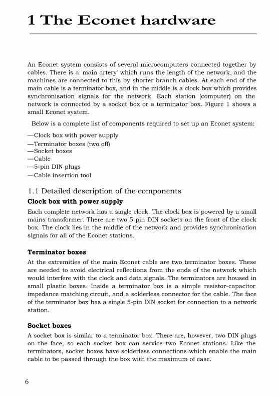
An Econet system consists of several microcomputers connected together by cables. There is a 'main artery' which runs the length of the network, and the machines are connected to this by shorter branch cables. At each end of the main cable is a terminator box, and in the middle is a clock box which provides synchronisation signals for the network. Each station (computer) on the network is connected by a socket box or a terminator box. Figure 1 shows a small Econet system.
Below is a complete list of components required to set up an Econet system:
—Clock box with power supply—Terminator boxes (two off)—Socket boxes—Cable—5-pin DIN plugs—Cable insertion tool
1.1 Detailed description of the components Clock box with power supplyEach complete network has a single clock. The clock box is powered by a small mains transformer. There are two 5-pin DIN sockets on the front of the clock box. The clock lies in the middle of the network and provides synchronisation signals for all of the Econet stations.
Terminator boxesAt the extremities of the main Econet cable are two terminator boxes. These are needed to avoid electrical reflections from the ends of the network which would interfere with the clock and data signals. The terminators are housed in small plastic boxes. Inside a terminator box is a simple resistor-capacitor impedance matching circuit, and a solderless connector for the cable. The face of the terminator box has a single 5-pin DIN socket for connection to a network station.
Socket boxesA socket box is similar to a terminator box. There are, however, two DIN plugs on the face, so each socket box can service two Econet stations. Like the terminators, socket boxes have solderless connections which enable the main cable to be passed through the box with the maximum of ease.
7
8
CableThe cable used throughout an Econet system consists of twin twisted-pair lines with a shield and ground wire. The signal lines are two data lines (D+ and D–) and two clock lines (C+ and C – ). There is a single ground wire. The total end-to-end resistance of the network should be less than 27 ohms, which will typically permit a main cable length of up to 500 metres.
The recommended specification for the cable is:
Characteristic impedance: 100 ohms ± 10% Mutual capacitance: less than 66pF per metre Propagation speed: greater than 0.5c
The following cables are recommended by Acorn:
Reliance RCC 8064 Brand Rex CD 84-4-0521 Radiospares 367-921
5-pin DIN plugsTwo of these are required to connect the main cables to the clock box. All other connections to the main cable can be made using the solderless connectors in the station and terminator boxes. Connections between stations and socket boxes are made using short (less than 2m), ready made 5-pin DIN to 5-pin DIN leads.
Cable insertion toolThis is required when wiring socket boxes. It is used to insert wires into the ID (insulation displacement) connectors in socket and terminator boxes. Rapid connection is possible without the use of a soldering iron.
9
2 Wiring and testing anetwork
2.1 WiringWhen wiring a system, there are several points to bear in mind.
– The clock should be placed centrally in the network.– The socket and terminator boxes should lie close to the stations.– The total length of the main cable should be less than 500m.– It is better to over estimate than under estimate the amount of cable
required.
To make identification of the signal wires easier, a colour coding system is used, as summarised in the table below:5-pin DIN number Signal Colour
1 Data+ White/orange4 Data– Orange2 Ground Copper5 Clock– Blue3 Clock+ White/blue
The Econet cable should be cut near to its centre. The two cut ends should be attached to a socket box, as described below (and shown in figure 1 above). For each side of the network, a 5-pin DIN to 5-pin DIN lead may then be used to connect the clock box to one of the DIN sockets in the socket box. The exact position of the clock box is not critical; within 30m of the centre of the main cable is sufficient.
After the clock has been connected, the cable should be laid out, passing close to the stations. The terminator boxes are connected as follows. Strip about 60mm (about 2.5 inches) of the outer insulator and shielding from the cable. Remove the lid from the terminator box to reveal the six white 'insulation displacement sockets'. These are marked with the letters E for ground, D+, D – , C– and C + . There are also two cable grips, one on each side of the printed circuit board.
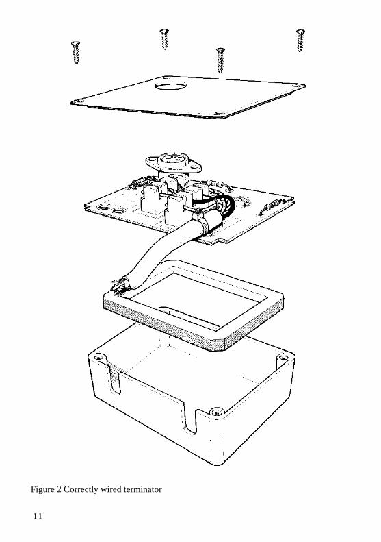
Lay the colour coded signal wires and the copper ground wire over the appropriate ID sockets and push them into place using the cable insertion tool. Be careful to ensure that the colour coding given above is adopted when fitting the wires. When the wires are in place the cable should be fastened to the board using the cable grips. Figure 2 shows a correctly wired terminator. After replacing the lid of the box, cut any excess cable protruding from the end.
10
When the terminator boxes have been fitted, stations may be connected to them using 5-pin DIN to 5-pin DIN cables. Installing a socket box is very similar to wiring a terminator box. The difference is that the outer insulator and shielding must be stripped without cutting the cable or earth wire. After removing about 60mm (2.5 inches) of the insulator, place the signal and ground wires over the ID sockets and push them into place with the tool. Again, the cable should be secured with the grips attached to the board.
2.2 TestingHaving installed the clock box, the terminator boxes and the socket boxes, you can test the wiring. The steps are as follows.
— Disconnect the clock from the network, so there are two free DIN plugs. The network is tested one half at a time.
— With an ohmmeter test the resistance between the two lines C+ and C— at the clock box DIN plug and at each socket box. The resistance should be less than 160 ohms if reliable operation is to be ensured.
— If a high resistance reading is obtained, there is an open circuit between the socket being tested and the clock box, possibly caused by data and clock lines being transposed at a socket box. If a very low resistance is obtained (less than 100 ohms), there is a short circuit between the socket being tested and the terminator. If no fault can be found in the cable, the terminator may be faulty.
— Repeat the test for the D+ and D— lines, but expect a resistance of 260 ohms for a healthy cable.
— Repeat the whole test sequence on the other half of the network.
11
Figure 2 Correctly wired terminator
12
3 Setting up an Econetsystem
3.1 Connecting the componentsWhen the wiring tests have been successfully completed, the Econet system can be activated. The stages involved are as follows:
—Connect the clock box in the middle of the network.—Connect the power supply to the clock box and turn it on.—The station identities must be set. This requires the alteration of links on the
computer's circuit board. See Appendix A for details. Note that station identities 254 and 235 are usually reserved for the file server and print server respectively.
—Check the voltages on the data lines. The voltage between ground and D+ should be between 1.8 and 2.2 volts. The voltage between D— and ground should be between 2.2 and 2.6 volts. If either of the readings is outside the correct range, check that the ground wire has the correct low resistance between each junction and the clock box. The network may seem to work correctly even if the data levels are wrong, but it won't be as reliable as it should be.
The machines on the network should now function correctly. To test this, connect a network machine to a socket box or terminator box and reset it, selecting the network filing system. See the machine's user guide for exact instructions on how to do this. As an example, on the BBC Microcomputer press N BREAK, releasing BREAK first. The message:
BBC Computer
Econet station 240
BASIC
should appear. The station number may be different. If this does not happen, read on.
3.2 Fault findingThere are several alternative messages to the one shown above. Each indicates a particular problem or set of problems with the network.
13
No clockThis may be caused by:
(a) The computer not being plugged into the network.(b) The clock box not being plugged into the mains.(c) The clock box not being plugged into the network.(d) An open circuit or short circuit in the clock lines.
Test for (a) by replacing the lead between the station on its socket box by a known good one.Test for (b) by checking the mains socket switch and the clock box power switch.Test for (c) by checking the 5-pin DIN plugs connecting the main cable to the clock box.Test for (d) by performing the checks described in section 2.2 on page 6.
If none of these faults seems to be present, try connecting a computer directly to the clock box by a short 5-pin DIN to 5-pin DIN lead. If there is still no clock, try another lead, then another BBC Microcomputer. Then check the clock setting inside the clock box. If none of these produces the desired results, the clock box may be faulty, and you should contact your dealer.
The errors discussed below may occur only after a network operation has been attempted, eg *CAT or *I A M <user id>.
Net errorThis may be caused by:
(a) An incorrect (too fast or slow) clock rate for the network.(b) The terminators not being connected properly to the network.(c) Bad wiring somewhere in the network (eg between socket boxes).
Point (a) may be remedied by checking the clock speed switches in the clock box. Upon removing the cover, you will see five links. One of these (LK1) is isolated and marked 1/2uS. The link should be set so that the central pin and the one marked 1uS are joined. The other four links (LK2 to LK5) are marked 8, 4, 2, 1 respectively. For normal network operation, the links marked 4 should be joined (LK3), or both the links marked 1 and 2 (LK5 and LK4) should be joined.
The speed at which the network operates is set by the links in the clock box in the following way. LK1 determines the 'base' time (in microseconds) of the network. This is normally 1uS, but may be changed to 2uS when low quality cable is used. The other links form a binary number determining the time in microseconds for which the clock is low. Thus when the links marked 1 and 2 are made, the clock low time is 3pS. If LK1 is set to 2RS, the sum of the other links' time must be doubled.
14
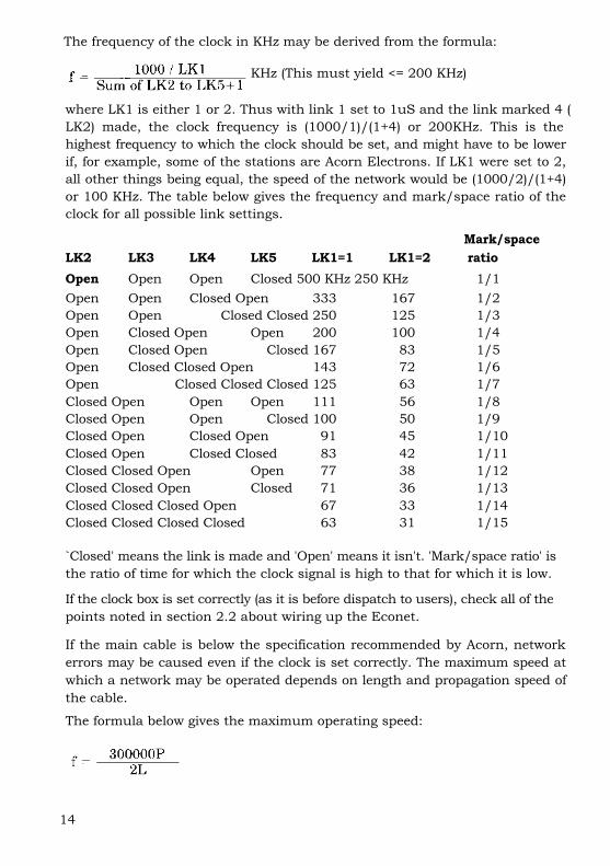
The frequency of the clock in KHz may be derived from the formula:
KHz (This must yield <= 200 KHz)
where LK1 is either 1 or 2. Thus with link 1 set to 1uS and the link marked 4 (LK2) made, the clock frequency is (1000/1)/(1+4) or 200KHz. This is the highest frequency to which the clock should be set, and might have to be lower if, for example, some of the stations are Acorn Electrons. If LK1 were set to 2, all other things being equal, the speed of the network would be (1000/2)/(1+4) or 100 KHz. The table below gives the frequency and mark/space ratio of the clock for all possible link settings.
Mark/space LK2 LK3 LK4 LK5 LK1=1 LK1=2 ratioOpen Open Open Closed 500 KHz 250 KHz 1/1Open Open Closed Open 333 167 1/2Open Open Closed Closed 250 125 1/3Open Closed Open Open 200 100 1/4Open Closed Open Closed 167 83 1/5Open Closed Closed Open 143 72 1/6Open Closed Closed Closed 125 63 1/7Closed Open Open Open 111 56 1/8Closed Open Open Closed 100 50 1/9Closed Open Closed Open 91 45 1/10Closed Open Closed Closed 83 42 1/11Closed Closed Open Open 77 38 1/12Closed Closed Open Closed 71 36 1/13Closed Closed Closed Open 67 33 1/14Closed Closed Closed Closed 63 31 1/15
`Closed' means the link is made and 'Open' means it isn't. 'Mark/space ratio' is the ratio of time for which the clock signal is high to that for which it is low.
If the clock box is set correctly (as it is before dispatch to users), check all of the points noted in section 2.2 about wiring up the Econet.
If the main cable is below the specification recommended by Acorn, network errors may be caused even if the clock is set correctly. The maximum speed at which a network may be operated depends on length and propagation speed of the cable.
The formula below gives the maximum operating speed:
15
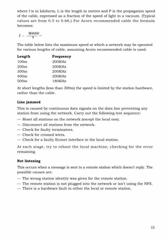
where f is in kilohertz, L is the length in metres and P is the propagation speed of the cable, expressed as a fraction of the speed of light in a vacuum. (Typical values are from 0.5 to 0.66.) For Acorn recommended cable the formula becomes:
The table below lists the maximum speed at which a network may be operated for various lengths of cable, assuming Acorn recommended cable is used.
Length Frequency100m 200KHz200m 200KHz300m 200KHz400m 200KHz500m 180KHz
At short lengths (less than 300m) the speed is limited by the station hardware, rather than the cable.
Line jammedThis is caused by continuous data signals on the data line preventing any station from using the network. Carry out the following test sequence:
— Reset all stations on the network (except the local one).— Disconnect all stations from the network.— Check for faulty terminators.— Check for crossed wires.— Check for a faulty Econet interface in the local station.
At each stage, try to reboot the local machine, checking for the error remaining.
Not listeningThis occurs when a message is sent to a remote station which doesn't reply. The possible causes are:
— The wrong station identity was given for the remote station.— The remote station is not plugged into the network or isn't using the NFS.— There is a hardware fault in either the local or remote station.
16
No replyThis can be caused by a remote machine having faulty peripherals that the local station is trying to access, eg disc drives on the file server and printer on the printer server.
Test that the peripheral works correctly when used locally, eg try a *CAT with the DFS selected on the file server, or print something from the printer server station. If these tests succeed, try replacing the server machine and the local machine that received the 'No reply'. If the operation now succeeds, isolate the faulty machine. If 'No reply' is still given at the local machine perform the tests described in section 2.2.
17
4 Bridges
For maximum performance, a single network's total length should be less than 500 metres. This places a constraint on the number of stations available, and more importantly, the range which the network can cover. To overcome this, network bridges have been developed to join two or more Econets. These enable users to log on to file servers on other networks, contact stations on other networks, and use printer servers on other networks. Only networks with file servers of level II and above may be used with bridges.
4.1 The bridge hardwareExternally, a bridge box looks very similar to a Second Processor or Prestel Adapter, ie a cream-coloured plastic box with the same cross-section as a BBC Microcomputer and one half of the width. On the back panel of the box are a mains lead, a power switch and two 5-pin DIN sockets marked A and B.
The circuitry of a bridge comprises two Econet interfaces, a 2MHz 6502 Processor, 8K of program EPROM and 8K of RAM. The RAM is used as workspace for the bridge software and as a buffer area between the two Econet interfaces.
To join two networks with a bridge, it is first necessary to assign a network number to each network. This may be in the range 1-127. Each network in the system should have a unique network number. Removing the lid of the bridge box reveals two rows of links. These are used to set the network identities, just as the links in the BBC machine set the station identity.
The links are situated on the left of the printed circuit board, about half way up. The row next to the component marked RP2 controls the identity of the network plugged into socket A; the links next to RP1 determine the identity of the network plugged into socket B. When the network identities have been decided upon, the links may be set in the same way as the station identity in a BBC Microcomputer, as described in Appendix A.
The most significant bit of the eight-bit network identity is at the bottom of the row, the least significant bit being the top link. As the range of legal identity numbers is 1-127, the bottom link of each row should always be made, remembering that a made link stands for a '0' in that position and an unmade link stands for a '1'. In order to set up an identity as 1, only the top link should be left unmade. To set the identity to 3, the top two links are left unmade, and so on.
18
Note: All bridges connected to a given network should have the network's identity set to the same number. Conversely, no two networks in a system connected by bridges may have the same network identity.
Once the network identities have been set up on the printed circuit board, the networks may be joined. This is achieved by attaching the bridge box to network A, exactly as though the bridge box were a normal station, ie by running a 5-pin DIN to 5-pin DIN lead from a junction or terminator box on the network to the socket marked A on the bridge box. Repeating the process for network B completes the joining process.
To activate the bridge, it simply has to be powered up. The bridge software detects which networks are in the system and begins its task of looking for messages to pass between the two networks that it bridges. Of the 8K of RAM in the bridge, about 4-6K is available for the purpose of buffering transactions between the two networks.
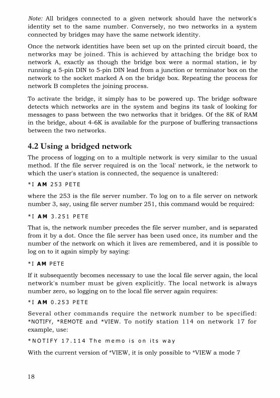
4.2 Using a bridged networkThe process of logging on to a multiple network is very similar to the usual method. If the file server required is on the 'local' network, ie the network to which the user's station is connected, the sequence is unaltered:
* I AM 253 PETE
where the 253 is the file server number. To log on to a file server on network number 3, say, using file server number 251, this command would be required:
* I A M 3 . 2 5 1 P E T E
That is, the network number precedes the file server number, and is separated from it by a dot. Once the file server has been used once, its number and the number of the network on which it lives are remembered, and it is possible to log on to it again simply by saying:
*I AM PETE
If it subsequently becomes necessary to use the local file server again, the local network's number must be given explicitly. The local network is always number zero, so logging on to the local file server again requires:
* I A M 0 . 2 5 3 P E T E
Several other commands require the network number to be specified: *NOTIFY, *REMOTE and *VIEW. To notify station 114 on network 17 for example, use:
* N O T I F Y 1 7 . 1 1 4 T h e m e m o i s o n i t s w a y
With the current version of *VIEW, it is only possible to *VIEW a mode 7
19
screen across networks. The reason is the limited size of the buffer memory: it is smaller than the memory used by all display modes except 7. If you attempt to *VIEW a soft screen mode (ie other than mode 7 on a BBC Microcomputer), the 'Mode' error message will be given (if you are in a smaller screen mode than the remote station), or your station will 'hang', waiting for the packet carrying the screen information to arrive. Since this gets rejected by the bridge software for being too big, it will never arrive. Future versions of *VIEW may overcome this problem.
While supervising a transaction between two networks, the bridge holds up one of the networks with a continuous empty message. This leads to a slight degradation in performance. In practice, though, most of the time taken by a transaction is waiting for the file server to process the command, and no speed difference should be noticed.
4.3 Typical network layoutsBridges enable various network layouts, or topologies, to be used that aren't normally available to Econet users. The connection between the main network cable and a station is limited to a length of two metres. This limits the network to a single linear layout with short 'spikes' at the junction and terminator boxes. This is often inconvenient, for example when the network has to service several floors of a building, especially when the length limit of 500m is considered.
By connecting networks with one or more bridges, different and more useful topologies may be set up. This section discusses two examples: E-type and star-type topologies.
E-type topologiesThis is useful when setting up a network work on several floors in a building. The idea is to have a single network running up the height of the building, with a bridge on each floor connecting this to the floor's own network. This topology is shown schematically overleaf.
20
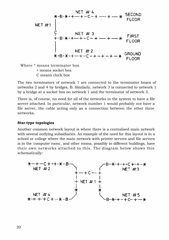
Where * means terminator box + means socket boxC means clock box
The two terminators of network 1 are connected to the terminator boxes of networks 2 and 4 by bridges, B. Similarly, network 3 is connected to network 1 by a bridge at a socket box on network 1 and the terminator of network 3.
There is, of course, no need for all of the networks in the system to have a file server attached. In particular, network number 1 would probably not have a file server, the cable acting only as a connection between the other three networks.
Star-type topologies
Another common network layout is where there is a centralised main network with several outlying subsidiaries. An example of the need for this layout is in a school or college where the main network with printer servers and file servers is in the 'computer room', and other rooms, possibly in different buildings, have their own networks attached to this. The diagram below shows this schematically:

21
Again, network number 1 is the main network, the others forming branches out from this.
It may be noted from the diagram above that stations on each network may reach stations on any other network, messages passing through up to two bridges. Of great importance is the fact that no message may reach its destination by more than one route. When connecting networks with bridges, it is vital that there are no duplicate routes (forming loops) between any of the systems. A simple way of detecting loops is: if n networks are connected by n or more bridges, there is bound to be a loop, and one or more of the bridges must be removed.
22
Appendix A: Setting thestation identity
The exact method by which the Econet identity is set depends on the station type, ie whether it is a BBC Microcomputer, Acorn Business Computer etc. This appendix describes these differences.
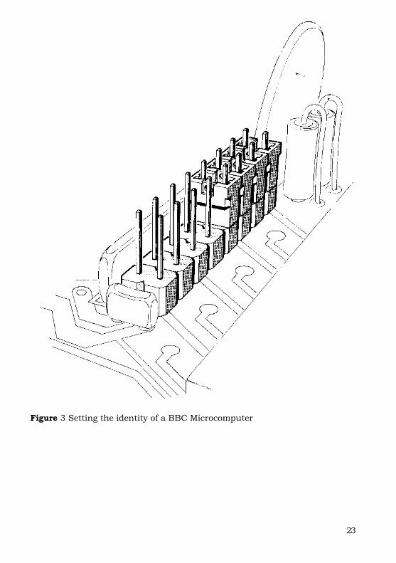
Setting a BBC Microcomputer's identityIn BBC machines with an Econet interface fitted there is a row of eight links in the top left corner of the printed circuit board, marked S11. To gain access to these links, the lid of the computer must be removed after unscrewing the four screws marked 'FIX'. Two of these are located at the rear of the computer's case and the other two are on the underside of the case at the front.
The links form an 8-bit binary number representing the computer's station identity. The least significant bit is the top link; the most significant bit is the bottom link. If a link is made, the bit is zero; an unmade link implies a one bit. As an example, to obtain station number 240 (128+64+32+16), links 0, 1, 2 and 3 should be made, and the rest unmade (counting the top link as number 0). This is shown in figure 3.
Setting an ABC's identityThe Econet links on the Acorn Business Computer are not readily accessible. You should ask your Acorn dealer to set the station identity to the required value.
23
Figure 3 Setting the identity of a BBC Microcomputer