Embed Size (px)
Citation preview
37430
Interface Software Version 1.xxxx
Manual 37430
easYgen-2000 Series Genset Control
Manual 37430 easYgen-2000 Series - Genset Control
Page 2/107 © Woodward
WARNING Read this entire manual and all other publications pertaining to the work to be performed before instal-ling, operating, or servicing this equipment. Practice all plant and safety instructions and precautions. Failure to follow instructions can cause personal injury and/or property damage. The engine, turbine, or other type of prime mover should be equipped with an overspeed (overtempera-ture, or overpressure, where applicable) shutdown device(s), that operates totally independently of the prime mover control device(s) to protect against runaway or damage to the engine, turbine, or other type of prime mover with possible personal injury or loss of life should the mechanical-hydraulic gov-ernor(s) or electric control(s), the actuator(s), fuel control(s), the driving mechanism(s), the linkage(s), or the controlled device(s) fail. Any unauthorized modifications to or use of this equipment outside its specified mechanical, electrical, or other operating limits may cause personal injury and/or property damage, including damage to the equipment. Any such unauthorized modifications: (i) constitute "misuse" and/or "negligence" within the meaning of the product warranty thereby excluding warranty coverage for any resulting damage, and (ii) invalidate product certifications or listings.
CAUTION To prevent damage to a control system that uses an alternator or battery-charging device, make sure the charging device is turned off before disconnecting the battery from the system. Electronic controls contain static-sensitive parts. Observe the following precautions to prevent dam-age to these parts. • Discharge body static before handling the control (with power to the control turned off, contact a
grounded surface and maintain contact while handling the control). • Avoid all plastic, vinyl, and Styrofoam (except antistatic versions) around printed circuit boards. • Do not touch the components or conductors on a printed circuit board with your hands or with
conductive devices.
OUT-OF-DATE PUBLICATION This publication may have been revised or updated since this copy was produced. To verify that you have the latest revision, be sure to check the Woodward website: http://www.woodward.com/pubs/current.pdf The revision level is shown at the bottom of the front cover after the publication number. The latest version of most publications is available at: http://www.woodward.com/publications If your publication is not there, please contact your customer service representative to get the latest copy.
Important definitions
WARNING Indicates a potentially hazardous situation that, if not avoided, could result in death or serious injury.
CAUTION Indicates a potentially hazardous situation that, if not avoided, could result in damage to equipment.
NOTE Provides other helpful information that does not fall under the warning or caution categories.
Woodward reserves the right to update any portion of this publication at any time. Information provided by Woodward is believed to be correct and reliable. However, Woodward assumes no responsibility unless otherwise expressly undertaken.
© Woodward
All Rights Reserved.
Manual 37430 easYgen-2000 Series - Genset Control
© Woodward Page 3/107
Revision History
Rev. Date Editor Changes NEW 09-06-09 TE Release
Contents
CHAPTER 1. GENERAL INFORMATION ....................................................................................... 7 Document Overview ................................................................................................................................. 7 Abbreviations ........................................................................................................................................... 7 Interface Overview ................................................................................................................................... 8
CAN Interfaces ............................................................................................................................... 9 Serial Interfaces ........................................................................................................................... 10
CHAPTER 2. CAN BUS CONFIGURATION ................................................................................. 12 CAN Bus Diagnosis ................................................................................................................................ 12
Load Diagnosis ............................................................................................................................ 12 Status Diagnosis .......................................................................................................................... 13
CAN Interface Parameters ..................................................................................................................... 14 Configure CAN Interface 1 ........................................................................................................... 14 Configure CAN Interface 2 ........................................................................................................... 18
CAN Bus Load Sharing .......................................................................................................................... 19 Multi-Master Principle .................................................................................................................. 19 Load Share Monitoring................................................................................................................. 19 General Load Share Information ................................................................................................. 19 Configure Load Share Parameters .............................................................................................. 20
Definition of CANopen Protocol Descriptions ........................................................................................ 21 Definition of CANopen Data Format ...................................................................................................... 21
Unsigned Integer .......................................................................................................................... 21 Signed Integer .............................................................................................................................. 22
J1939 Protocol Display Messages ......................................................................................................... 23 Displayed Messages .................................................................................................................... 23
Remote Control via CAN ........................................................................................................................ 26 Remote Start/Stop and Acknowledgement .................................................................................. 26 Transmitting a Frequency Set Point via CANopen ...................................................................... 31 Transmitting a Voltage Set Point via CANopen ........................................................................... 33 Transmitting a Power Factor Set Point via CANopen .................................................................. 34 Transmitting a Power Set Point via CANopen ............................................................................. 36 Transmitting Multiple Set Points via CANopen ............................................................................ 38 Remotely Changing the Set Point via CANopen ......................................................................... 39 Transmitting a Remote Control Bit via CANopen ........................................................................ 42
Sending a Data Protocol via TPDO ....................................................................................................... 43 Cyclically Sending of Data ........................................................................................................... 43 Sending of Data on Request ........................................................................................................ 43
External IOs on CAN Interface 1 ............................................................................................................ 45 External DOs for an IKD 1 ........................................................................................................... 45 Receiving Data from an IKD 1 ..................................................................................................... 45
Troubleshooting ..................................................................................................................................... 46 General ........................................................................................................................................ 46 Guidance Level CAN Bus #1 ....................................................................................................... 46
Manual 37430 easYgen-2000 Series - Genset Control
Page 4/107 © Woodward
CHAPTER 3. MODBUS COMMUNICATIONS ................................................................................ 47 General Information ............................................................................................................................... 47 Address Range ...................................................................................................................................... 48 Visualization ........................................................................................................................................... 49 Configuration ......................................................................................................................................... 50 Remote Control via Modbus .................................................................................................................. 51
Remote Start, Stop, and Acknowledgement via Modbus ............................................................ 51 Set Point Setting .......................................................................................................................... 53 Remotely Changing the Set Point ............................................................................................... 57
Changing Parameter Settings via Modbus ............................................................................................ 59 Parameter Setting........................................................................................................................ 59 Configuration of the LogicsManager Functions via Modbus ....................................................... 61 Operating Modes ......................................................................................................................... 63 Configuration of Remote Start/Stop and Acknowledgement ....................................................... 64 Remote Acknowledging Single Alarm Messages ........................................................................ 69 Remotely Clearing The Event History ......................................................................................... 70 Remotely Resetting the Default Values....................................................................................... 71
Exception Responses ............................................................................................................................ 73 Modbus Parameters .............................................................................................................................. 74
APPENDIX A. SUPPORTED J1939 ECUS & REMOTE CONTROL MESSAGES ............................... 75
APPENDIX B. DATA PROTOCOLS ............................................................................................ 77 Data Protocol 5100 ................................................................................................................................ 77 Data Protocol 5101 ................................................................................................................................ 90 Data Protocol 6000 (Load Share Message) .......................................................................................... 99
General ........................................................................................................................................ 99 Timing .......................................................................................................................................... 99
Data Protocol 65000 ............................................................................................................................ 102 Data Protocol 65001 ............................................................................................................................ 102 Additional Data Protocol Parameters .................................................................................................. 103
Remote Control Word 1 - Object 21F7h (Parameter ID 503) .................................................... 103 Remote Control Word 2 - Object 21F8h (Parameter ID 504) .................................................... 104 Remote Control Word 3 - Object 21F9h (Parameter ID 505) .................................................... 105 Remote Active Power Set Point - Object 21FBh (Parameter ID 507) ....................................... 105 Remote Power Factor Set Point - Object 21FCh (Parameter ID 508) ...................................... 105 Remote Frequency Set Point - Object 21FDh (Parameter ID 509) ........................................... 105 Remote Voltage Set Point - Object 21FEh (Parameter ID 510) ................................................ 105 Remote External DO Control - Object 34F5h (Parameter ID 8005) .......................................... 106 Remote External DI Request - Object 3F4Dh (Parameter ID 8014) ......................................... 106
Manual 37430 easYgen-2000 Series - Genset Control
© Woodward Page 5/107
Figures and Tables
Figures Figure 1-1: easYgen - interface overview ............................................................................................................. 8 Figure 1-2: Interface overview - CAN interfaces .................................................................................................. 9 Figure 1-3: Interface overview - serial interfaces .................................................................................................10 Figure 1-4: Interface overview - serial interface Modbus half-duplex .................................................................11 Figure 2-1: CAN bus load diagnostic screen ........................................................................................................12 Figure 2-2: CAN interface state screen ................................................................................................................13 Figure 2-3: Interfaces - principle of PDO mapping ..............................................................................................15 Figure 2-4: Display screen - CAN interface 1 config. ..........................................................................................27 Figure 2-5: Display screen - Receive PDO 1 .......................................................................................................27 Figure 2-6: CANopen request data .......................................................................................................................28 Figure 2-7: CANopen request data for Node ID 1 ...............................................................................................28 Figure 2-8: Display screen - CAN interface 1 config. ..........................................................................................29 Figure 2-9: CANopen request data for Node ID 2 ...............................................................................................29 Figure 2-10: Display screen - Additional Server SDOs .......................................................................................30 Figure 2-11: CANopen request data for additional Server SDO ..........................................................................31 Figure 2-12: Display screen - Receive PDO 1 for frequency set point .................................................................31 Figure 2-13: CANopen send data for frequency set point ....................................................................................32 Figure 2-14: CANopen send data for Node ID 1 for frequency set point .............................................................32 Figure 2-15: Display screen - Receive PDO 1 for voltage set point .....................................................................33 Figure 2-16: CANopen send data for voltage set point ........................................................................................34 Figure 2-17: Display screen - Receive PDO 1 for power factor set point ............................................................35 Figure 2-18: CANopen send data for power factor set point ................................................................................35 Figure 2-19: CANopen send data for Node ID 1 for power factor set point ........................................................36 Figure 2-20: Display screen - Receive PDO 1 for power set point ......................................................................37 Figure 2-21: CANopen send data for power set point ..........................................................................................37 Figure 2-22: Display screen - Receive PDO 1 for multiple set points ..................................................................38 Figure 2-23: CANopen send data for multiple set points .....................................................................................39 Figure 2-24: Display screen - Receive PDO 1 for changing the set point ............................................................40 Figure 2-25: CANopen send data for changing the set point ...............................................................................40 Figure 2-26: CANopen send data for Node ID 1 for changing the set point ........................................................41 Figure 2-27: Display screen - Receive PDO 1 for frequency set point .................................................................42 Figure 2-28: CANopen send data for setting a remote control bit ........................................................................42 Figure 2-29: Cyclical sending of data - TPDO configuration ..............................................................................43 Figure 2-30: Sending of data on request - TPDO configuration ...........................................................................43 Figure 2-31: Cyclical sending of data - Sync Message request ............................................................................44 Figure 2-32: Cyclical sending of data - reply .......................................................................................................44 Figure 3-1: Modbus - visualization configurations ..............................................................................................49 Figure 3-2: Modbus - remote control parameter 503 ...........................................................................................51 Figure 3-3: Modbus - write register - start request ...............................................................................................52 Figure 3-4: Modbus - write register - stop request ...............................................................................................52 Figure 3-5: Modbus - write register - external acknowledge................................................................................52 Figure 3-6: Set point source configuration ...........................................................................................................53 Figure 3-7: Modbus - configuration example 4 - active power ............................................................................54 Figure 3-8: Modbus - configuration example 4 - active power ............................................................................54 Figure 3-9: Modbus - configuration example 4 - active power ............................................................................54 Figure 3-10: Modbus - configuration example 4 - active power ..........................................................................55 Figure 3-11: Modbus - configuration example 4 - power factor ..........................................................................55 Figure 3-12: Modbus - configuration example 4 - frequency ...............................................................................56 Figure 3-13: Modbus - configuration example 4 - voltage ...................................................................................56 Figure 3-14: Modbus - remote control parameter 504..........................................................................................57 Figure 3-15: Modbus - write register - enable active power set point 2 ...............................................................58 Figure 3-16: Modbus - write register - enable power factor set point 2 ...............................................................58 Figure 3-17: Modbus - write register - enable frequency set point 2 ....................................................................58 Figure 3-18: Modbus - write register - enable voltage set point 2 ........................................................................58 Figure 3-19: Modbus - configuration example 1 ..................................................................................................59 Figure 3-20: Modbus - configuration example 2 ..................................................................................................60 Figure 3-21: Modbus - configuration example 3 ..................................................................................................60 Figure 3-22: LogicsManager - Modbus encoding ................................................................................................61 Figure 3-23: LogicsManager - Modbus encoding - example ...............................................................................62 Figure 3-24: Modbus - LogicsManager example - Operat. Mode AUTO ............................................................63
Manual 37430 easYgen-2000 Series - Genset Control
Page 6/107 © Woodward
Figure 3-25: Modbus configuration - Operat. mode AUTO................................................................................. 64 Figure 3-26: Modbus - LogicsManager example - Start req. in AUTO ............................................................... 65 Figure 3-27: Modbus configuration - Start req in AUTO .................................................................................... 65 Figure 3-28: Modbus - LogicsManager example - External acknowledge ........................................................... 66 Figure 3-29: Modbus configuration - External acknowledge ............................................................................... 67 Figure 3-30: Modbus - LogicsManager example - Start w/o Load ...................................................................... 67 Figure 3-31: Modbus configuration - Start w/o load ............................................................................................ 68 Figure 3-32: Modbus - remote control parameter 522 ......................................................................................... 69 Figure 3-33: Modbus - write register - acknowledge alarm message ................................................................... 69 Figure 3-34: Modbus - remote control parameter 1706 ....................................................................................... 70 Figure 3-35: Modbus - write register - clear event history ................................................................................... 70 Figure 3-36: Modbus - remote control parameter 1704 ....................................................................................... 71 Figure 3-37: Modbus - write register - enable the resetting procedure via RS-232 .............................................. 71 Figure 3-38: Modbus - remote control parameter 1701 ....................................................................................... 72 Figure 3-39: Modbus - write register - resetting the default values...................................................................... 72 Figure 3-40: Remote control - start/stop priority ............................................................................................... 104
Tables Table 1-1: Manual - overview ................................................................................................................................ 7 Table 1-2: Interfaces – overview............................................................................................................................ 8 Table 2-1: CAN bus - CAN interface 1 - parameters ........................................................................................... 14 Table 2-2: CAN bus - CAN interface 1 - additional server SDOs - parameters ................................................... 14 Table 2-3: CAN bus - CAN interface 1 - receive PDO 1 - parameters ................................................................ 15 Table 2-4: CAN bus - CAN interface 1 - receive PDO 2 - parameters ................................................................ 15 Table 2-5: CAN bus - CAN interface 1 - receive PDO 3 - parameters ................................................................ 15 Table 2-6: CAN bus - CAN interface 1 - transmit PDO 1 - parameters ............................................................... 16 Table 2-7: CAN bus - CAN interface 1 - transmit PDO 2 - parameters ............................................................... 16 Table 2-8: CAN bus - CAN interface 1 - transmit PDO 3 - parameters ............................................................... 17 Table 2-9: CAN bus - CAN interface 2 - parameters ........................................................................................... 18 Table 2-10: CAN bus - CAN interface 2 - CANopen - parameters ...................................................................... 18 Table 2-11: CAN bus - CAN interface 2 - J1939 - parameters ............................................................................ 18 Table 2-12: CAN bus - CAN interface 2 - load share parameters ........................................................................ 20 Table 2-13: CAN bus - transfer syntax for data type UNSIGNEDn .................................................................... 21 Table 2-14: CAN bus - transfer syntax for data type INTEGERn ........................................................................ 22 Table 2-15: J1939 protocol - standard messages .................................................................................................. 25 Table 2-16: J1939 protocol - special EMR messages........................................................................................... 25 Table 2-17: J1939 protocol - special S6 messages ............................................................................................... 25 Table 3-1: Modbus - address range ...................................................................................................................... 48 Table 3-2: Modbus - address range block read .................................................................................................... 49 Table 3-3: Modbus - address calculation ............................................................................................................. 50 Table 3-4: Modbus - data types ............................................................................................................................ 50 Table 3-5: Modbus - exception responses ............................................................................................................ 73 Table 3-6: Modbus - serial interface 1 - parameters ............................................................................................. 74 Table 3-7: Modbus - serial interface 2 - parameters ............................................................................................. 74 Table 3-8: Load share message - example ........................................................................................................... 99 Table 3-9: Load share line - max. length ............................................................................................................. 99 Table 3-10: Remote control telegram ................................................................................................................ 103
Manual 37430 easYgen-2000 Series - Genset Control
© Woodward Page 7/107
Chapter 1. General Information
Document Overview ≡≡≡≡≡≡≡≡≡≡≡≡≡≡≡≡≡≡≡≡≡≡≡≡≡
Type English German easYgen-2000 Series easYgen-2000 Series - Installation 37426 GR37426 easYgen-2000 Series - Configuration 37427 GR37427 easYgen-2000 Series - Operation 37428 GR37428 easYgen-2000 Series - Application 37429 - easYgen-2000 Series - Interfaces this manual 37430 - easYgen-2000 Series - Parameter List 37431 GR37431 easYgen-2000 Series - Brief Operation Informa-
tion 37432 GR37432
Table 1-1: Manual - overview
Intended Use The unit must only be operated in the manner described by this manual. The prerequisite for a proper and safe operation of the product is correct transportation, storage, and installation as well as careful oper-ation and maintenance.
NOTE This manual has been developed for a unit fitted with all available options. Inputs/outputs, functions, configuration screens, and other details described, which do not exist on your unit, may be ignored. The present manual has been prepared to enable the installation and commissioning of the unit. Due to the large variety of parameter settings, it is not possible to cover every combination. The manual is therefore only a guide. In case of incorrect entries or a total loss of functions, the default settings may be taken from the list of parameters enclosed in the configuration manual 37427 or from ToolKit and the respective *.SID file.
Abbreviations ≡≡≡≡≡≡≡≡≡≡≡≡≡≡≡≡≡≡≡≡≡≡≡≡≡
The following abbreviations are frequently used in this documents:
• PDO Process Data Object • RPDO Receive PDO • TPDO Transmit PDO • SDO Service Data Object • SSDO Server SDO • MSB Most Significant Bit • LSB Least Significant Bit
Manual 37430 easYgen-2000 Series - Genset Control
Page 8/107 © Woodward
Interface Overview ≡≡≡≡≡≡≡≡≡≡≡≡≡≡≡≡≡≡≡≡≡≡≡≡≡
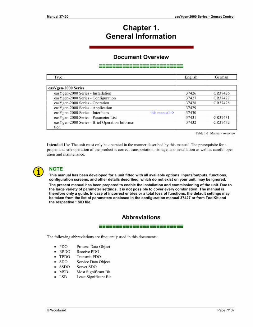
Depending on the respective model and package, the easYgen-2000 Series provides up to 2 CAN interfaces and 2 serial interfaces. Table 1-2 indicates the interface set up of respective model and package.
Interface(s) CAN Serial RS-485
Service Port RS-232
easYgen-2200 P1 1 - 1 easYgen-2200 P2 2 - 1 easYgen-2500 P1 2 1 1
Table 1-2: Interfaces – overview
CAN bus 1 - CANopen (Protocol 5100) CAN bus 2 - CANopen (IKD 1 and Phoenix expansion boards)
- J1939 ECU RS-485 - Modbus (Protocol 5100) Service Port (RS-232)
- Toolkit ( Servlink), - Modbus (Protocol 5100)
Figure 1-1: easYgen - interface overview
Manual 37430 easYgen-2000 Series - Genset Control
© Woodward Page 9/107
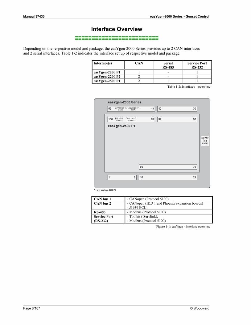
CAN Interfaces
Figure 1-2: Interface overview - CAN interfaces
CAN Interface 1 – Freely Configurable CANopen Interface
CAN interface 1 is a freely configurable CANopen interface with 3 RPDOs (receive boxes), 3 TPDOs (send box-es), and 4 additional Server SDOs.
CAN Interface 2 (Engine Bus)
The CAN interface 2 supports the CANopen and J1939 protocol simultaneously. It supports the connection of a wide range of engine control units (ECUs) and J1939 analog input control modules, which comply with the J1939 standard (e.g. Axiomatic).
Pre-Configured CANopen Interface CAN interface 2 is pre-configured for several expansion units. These include the I/O expansion boards Wood-ward IKD 1 and several combinations of the expansion boards of the Phoenix Inline Modular (IL) series. It is possible to connect several combinations of up to four Woodward IKD 1s and Phoenix Inline Modular (IL) modules with up to 16 discrete inputs/outputs. Refer to the Application Manual 37429 for a list of example confi-gurations of different load sharing applications.
Monitoring
The two CAN interfaces may be monitored individually. Refer to the Configuration Manual 37427 for more in-formation about this monitoring function with a dedicated alarm message and reaction for each interface.
CAN Bus Diagnosis
The state and the load of the CAN interfaces can be monitored. Refer to CAN Bus Diagnosis on page 12 for de-tailed information.
Manual 37430 easYgen-2000 Series - Genset Control
Page 10/107 © Woodward
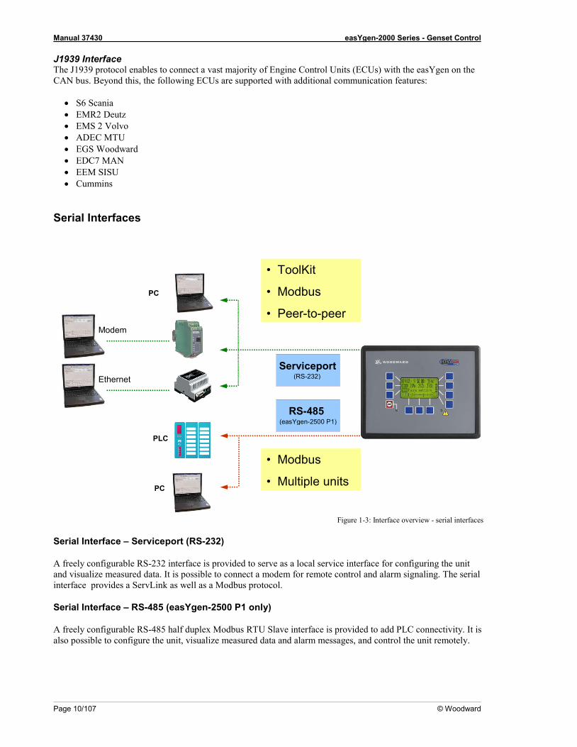
J1939 Interface The J1939 protocol enables to connect a vast majority of Engine Control Units (ECUs) with the easYgen on the CAN bus. Beyond this, the following ECUs are supported with additional communication features:
• S6 Scania • EMR2 Deutz • EMS 2 Volvo • ADEC MTU • EGS Woodward • EDC7 MAN • EEM SISU • Cummins
Serial Interfaces
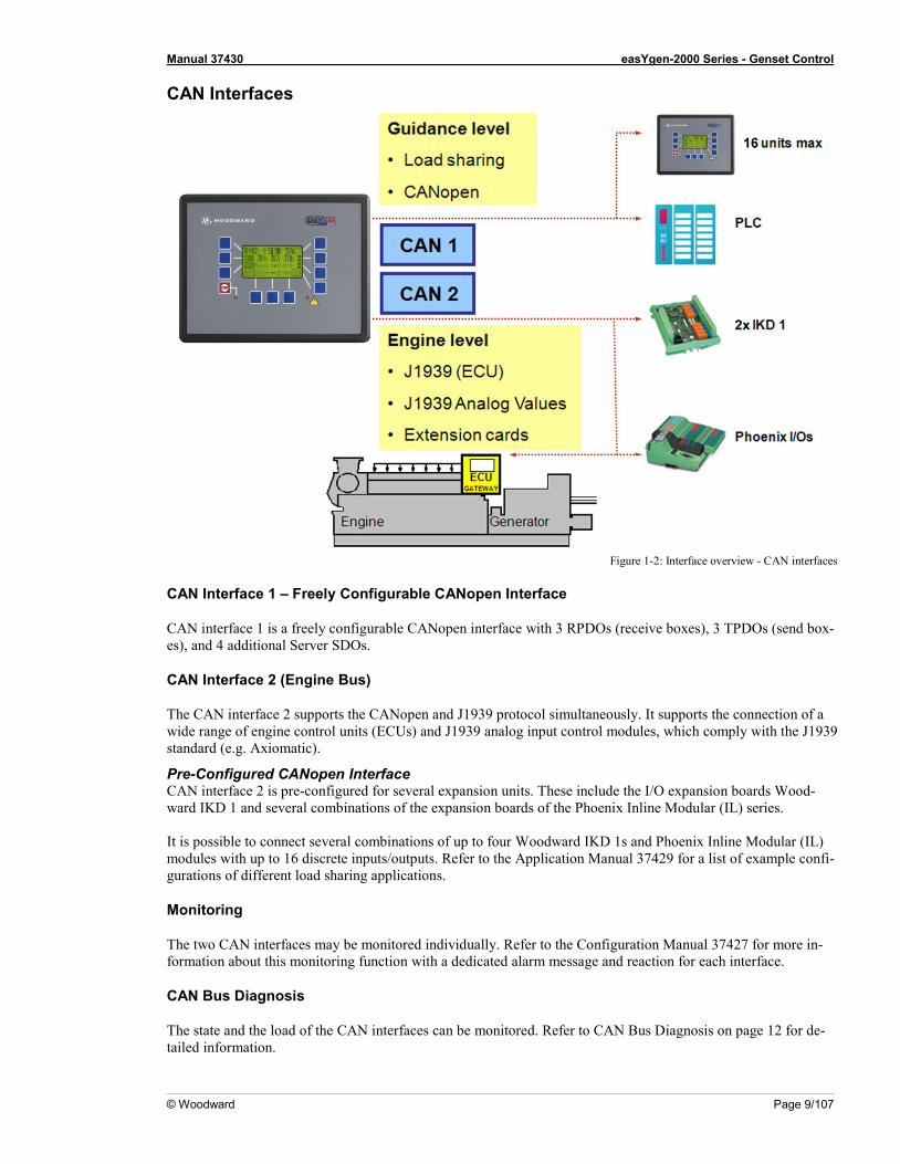
Figure 1-3: Interface overview - serial interfaces
Serial Interface – Serviceport (RS-232)
A freely configurable RS-232 interface is provided to serve as a local service interface for configuring the unit and visualize measured data. It is possible to connect a modem for remote control and alarm signaling. The serial interface provides a ServLink as well as a Modbus protocol.
Serial Interface – RS-485 (easYgen-2500 P1 only)
A freely configurable RS-485 half duplex Modbus RTU Slave interface is provided to add PLC connectivity. It is also possible to configure the unit, visualize measured data and alarm messages, and control the unit remotely.
(easYgen-2500 P1) RS-485
(RS-232) Serviceport
Modem
• ToolKit
• Modbus
• Peer - to - peer
• Modbus
• Multiple units
PLC
Ethernet
PC
PC
Manual 37430 easYgen-2000 Series - Genset Control
© Woodward Page 11/107
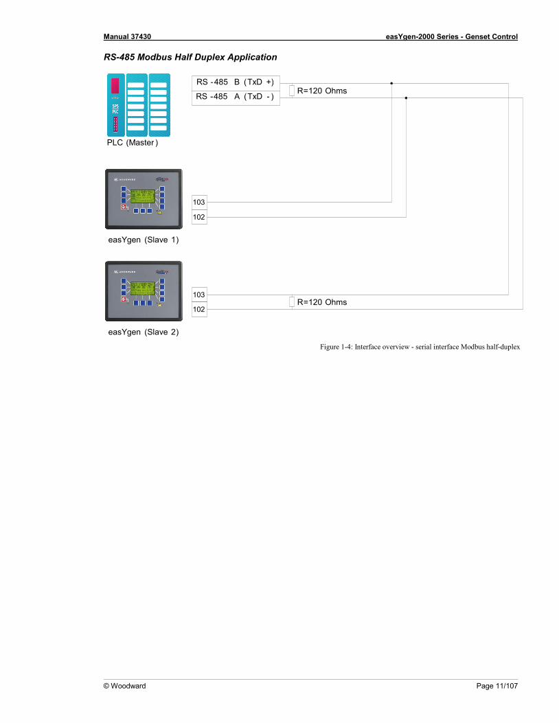
RS-485 Modbus Half Duplex Application
Figure 1-4: Interface overview - serial interface Modbus half-duplex
103
102
RS - 485 B ( TxD +)
RS - 485 A ( TxD - )
103
102
R = 120 Ohms
R = 120 Ohms
PLC ( Master )
easYgen ( Slave 1 )
easYgen ( Slave 2 )
Manual 37430 easYgen-2000 Series - Genset Control
Page 12/107 © Woodward
Chapter 2. CAN Bus Configuration
CAN Bus Diagnosis ≡≡≡≡≡≡≡≡≡≡≡≡≡≡≡≡≡≡≡≡≡≡≡≡≡
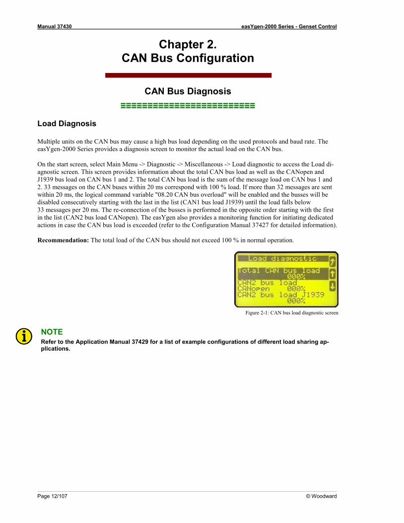
Load Diagnosis Multiple units on the CAN bus may cause a high bus load depending on the used protocols and baud rate. The easYgen-2000 Series provides a diagnosis screen to monitor the actual load on the CAN bus. On the start screen, select Main Menu -> Diagnostic -> Miscellaneous -> Load diagnostic to access the Load di-agnostic screen. This screen provides information about the total CAN bus load as well as the CANopen and J1939 bus load on CAN bus 1 and 2. The total CAN bus load is the sum of the message load on CAN bus 1 and 2. 33 messages on the CAN buses within 20 ms correspond with 100 % load. If more than 32 messages are sent within 20 ms, the logical command variable "08.20 CAN bus overload" will be enabled and the busses will be disabled consecutively starting with the last in the list (CAN1 bus load J1939) until the load falls below 33 messages per 20 ms. The re-connection of the busses is performed in the opposite order starting with the first in the list (CAN2 bus load CANopen). The easYgen also provides a monitoring function for initiating dedicated actions in case the CAN bus load is exceeded (refer to the Configuration Manual 37427 for detailed information). Recommendation: The total load of the CAN bus should not exceed 100 % in normal operation.
Figure 2-1: CAN bus load diagnostic screen
NOTE Refer to the Application Manual 37429 for a list of example configurations of different load sharing ap-plications.
Manual 37430 easYgen-2000 Series - Genset Control
© Woodward Page 13/107
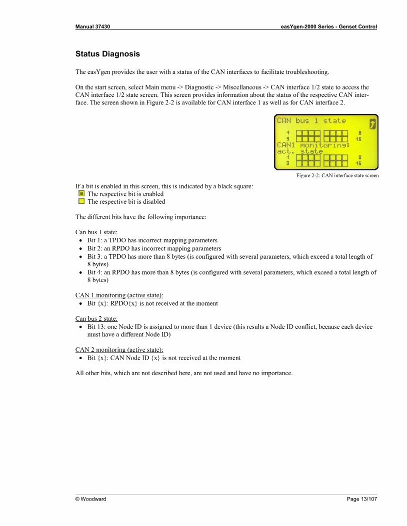
Status Diagnosis The easYgen provides the user with a status of the CAN interfaces to facilitate troubleshooting. On the start screen, select Main menu -> Diagnostic -> Miscellaneous -> CAN interface 1/2 state to access the CAN interface 1/2 state screen. This screen provides information about the status of the respective CAN inter-face. The screen shown in Figure 2-2 is available for CAN interface 1 as well as for CAN interface 2.
Figure 2-2: CAN interface state screen
If a bit is enabled in this screen, this is indicated by a black square: The respective bit is enabled The respective bit is disabled
The different bits have the following importance: Can bus 1 state: • Bit 1: a TPDO has incorrect mapping parameters • Bit 2: an RPDO has incorrect mapping parameters • Bit 3: a TPDO has more than 8 bytes (is configured with several parameters, which exceed a total length of
8 bytes) • Bit 4: an RPDO has more than 8 bytes (is configured with several parameters, which exceed a total length of
8 bytes) CAN 1 monitoring (active state): • Bit {x}: RPDO{x} is not received at the moment
Can bus 2 state: • Bit 13: one Node ID is assigned to more than 1 device (this results a Node ID conflict, because each device
must have a different Node ID) CAN 2 monitoring (active state): • Bit {x}: CAN Node ID {x} is not received at the moment
All other bits, which are not described here, are not used and have no importance.
Manual 37430 easYgen-2000 Series - Genset Control
Page 14/107 © Woodward
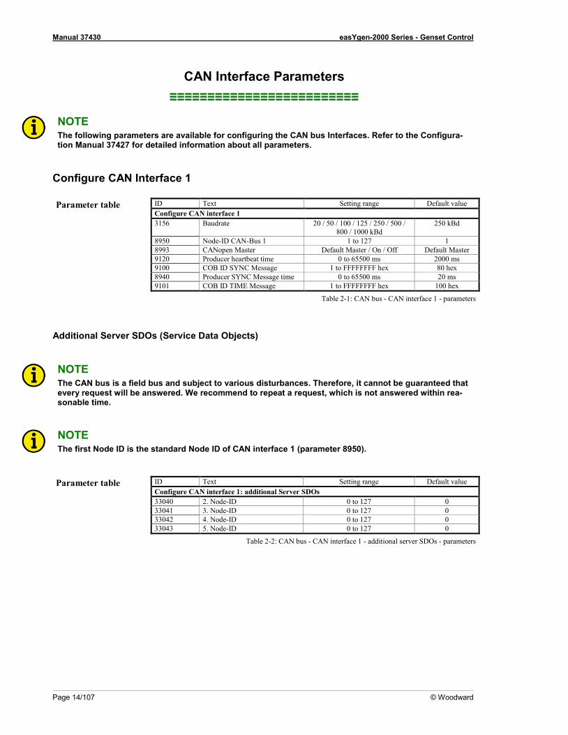
CAN Interface Parameters ≡≡≡≡≡≡≡≡≡≡≡≡≡≡≡≡≡≡≡≡≡≡≡≡≡
NOTE The following parameters are available for configuring the CAN bus Interfaces. Refer to the Configura-tion Manual 37427 for detailed information about all parameters.
Configure CAN Interface 1 Parameter table ID Text Setting range Default value
Configure CAN interface 1 3156 Baudrate 20 / 50 / 100 / 125 / 250 / 500 /
800 / 1000 kBd 250 kBd
8950 Node-ID CAN-Bus 1 1 to 127 1 8993 CANopen Master Default Master / On / Off Default Master 9120 Producer heartbeat time 0 to 65500 ms 2000 ms 9100 COB ID SYNC Message 1 to FFFFFFFF hex 80 hex 8940 Producer SYNC Message time 0 to 65500 ms 20 ms 9101 COB ID TIME Message 1 to FFFFFFFF hex 100 hex
Table 2-1: CAN bus - CAN interface 1 - parameters
Additional Server SDOs (Service Data Objects)
NOTE The CAN bus is a field bus and subject to various disturbances. Therefore, it cannot be guaranteed that every request will be answered. We recommend to repeat a request, which is not answered within rea-sonable time.
NOTE The first Node ID is the standard Node ID of CAN interface 1 (parameter 8950).
Parameter table ID Text Setting range Default value
Configure CAN interface 1: additional Server SDOs 33040 2. Node-ID 0 to 127 0 33041 3. Node-ID 0 to 127 0 33042 4. Node-ID 0 to 127 0 33043 5. Node-ID 0 to 127 0
Table 2-2: CAN bus - CAN interface 1 - additional server SDOs - parameters
Manual 37430 easYgen-2000 Series - Genset Control
© Woodward Page 15/107
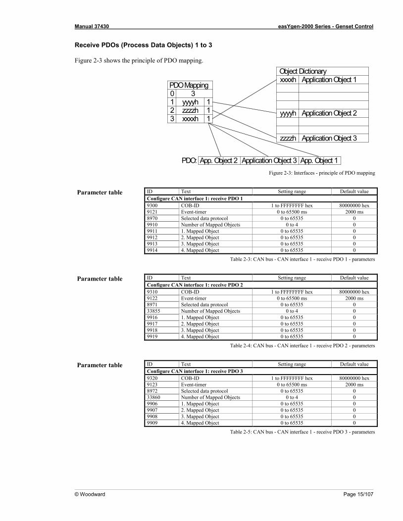
Receive PDOs (Process Data Objects) 1 to 3
Figure 2-3 shows the principle of PDO mapping.
Figure 2-3: Interfaces - principle of PDO mapping
Parameter table ID Text Setting range Default value
Configure CAN interface 1: receive PDO 1 9300 COB-ID 1 to FFFFFFFF hex 80000000 hex 9121 Event-timer 0 to 65500 ms 2000 ms 8970 Selected data protocol 0 to 65535 0 9910 Number of Mapped Objects 0 to 4 0 9911 1. Mapped Object 0 to 65535 0 9912 2. Mapped Object 0 to 65535 0 9913 3. Mapped Object 0 to 65535 0 9914 4. Mapped Object 0 to 65535 0
Table 2-3: CAN bus - CAN interface 1 - receive PDO 1 - parameters
Parameter table ID Text Setting range Default value
Configure CAN interface 1: receive PDO 2 9310 COB-ID 1 to FFFFFFFF hex 80000000 hex 9122 Event-timer 0 to 65500 ms 2000 ms 8971 Selected data protocol 0 to 65535 0 33855 Number of Mapped Objects 0 to 4 0 9916 1. Mapped Object 0 to 65535 0 9917 2. Mapped Object 0 to 65535 0 9918 3. Mapped Object 0 to 65535 0 9919 4. Mapped Object 0 to 65535 0
Table 2-4: CAN bus - CAN interface 1 - receive PDO 2 - parameters
Parameter table ID Text Setting range Default value
Configure CAN interface 1: receive PDO 3 9320 COB-ID 1 to FFFFFFFF hex 80000000 hex 9123 Event-timer 0 to 65500 ms 2000 ms 8972 Selected data protocol 0 to 65535 0 33860 Number of Mapped Objects 0 to 4 0 9906 1. Mapped Object 0 to 65535 0 9907 2. Mapped Object 0 to 65535 0 9908 3. Mapped Object 0 to 65535 0 9909 4. Mapped Object 0 to 65535 0
Table 2-5: CAN bus - CAN interface 1 - receive PDO 3 - parameters
0123
3111
yyyyhzzzzhxxxxh
xxxxh
zzzzh
yyyyh
PDO Mapping
Object DictionaryApplication Object 1
Application Object 2
Application Object 3
App. Object 2 Application Object 3 App. Object 1PDO:

Manual 37430 easYgen-2000 Series - Genset Control
Page 16/107 © Woodward
NOTE Do not configure an RPDO or TPDO with a COB-ID higher than 580 (hex) or lower than 180 (hex). These IDs are reserved for internal purposes.
Transmit PDOs (Process Data Objects) 1 to 3
Parameter table ID Text Setting range Default value
Configure CAN interface 1: transmit PDO 1 9600 COB-ID 1 to FFFFFFFF hex 00000181 hex 9602 Transmission type 0 to 255 255 9604 Event timer 0 to 65500 ms 20 ms 8962 Selected data protocol 0 to 65535 5100 9609 Number of Mapped Objects 0 to 4 0 9605 1. Mapped Object 0 to 65535 0 9606 2. Mapped Object 0 to 65535 0 9607 3. Mapped Object 0 to 65535 0 9608 4. Mapped Object 0 to 65535 0
Table 2-6: CAN bus - CAN interface 1 - transmit PDO 1 - parameters
Parameter table ID Text Setting range Default value
Configure CAN interface 1: transmit PDO 2 9610 COB-ID 1 to FFFFFFFF hex 80000000 hex 9612 Transmission type 0 to 255 255 9614 Event timer 0 to 65500 ms 20 ms 8963 Selected data protocol 0 to 65535 0 9619 Number of Mapped Objects 0 to 4 0 9615 1. Mapped Object 0 to 65535 0 9616 2. Mapped Object 0 to 65535 0 9617 3. Mapped Object 0 to 65535 0 9618 4. Mapped Object 0 to 65535 0
Table 2-7: CAN bus - CAN interface 1 - transmit PDO 2 - parameters
Manual 37430 easYgen-2000 Series - Genset Control
© Woodward Page 17/107
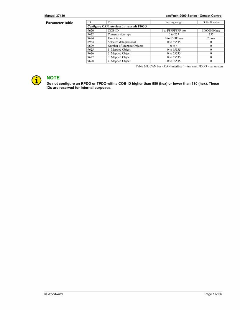
Parameter table ID Text Setting range Default value Configure CAN interface 1: transmit PDO 3 9620 COB-ID 1 to FFFFFFFF hex 80000000 hex 9622 Transmission type 0 to 255 255 9624 Event timer 0 to 65500 ms 20 ms 8964 Selected data protocol 0 to 65535 0 9629 Number of Mapped Objects 0 to 4 0 9625 1. Mapped Object 0 to 65535 0 9626 2. Mapped Object 0 to 65535 0 9627 3. Mapped Object 0 to 65535 0 9628 4. Mapped Object 0 to 65535 0
Table 2-8: CAN bus - CAN interface 1 - transmit PDO 3 - parameters
NOTE Do not configure an RPDO or TPDO with a COB-ID higher than 580 (hex) or lower than 180 (hex). These IDs are reserved for internal purposes.
Manual 37430 easYgen-2000 Series - Genset Control
Page 18/107 © Woodward
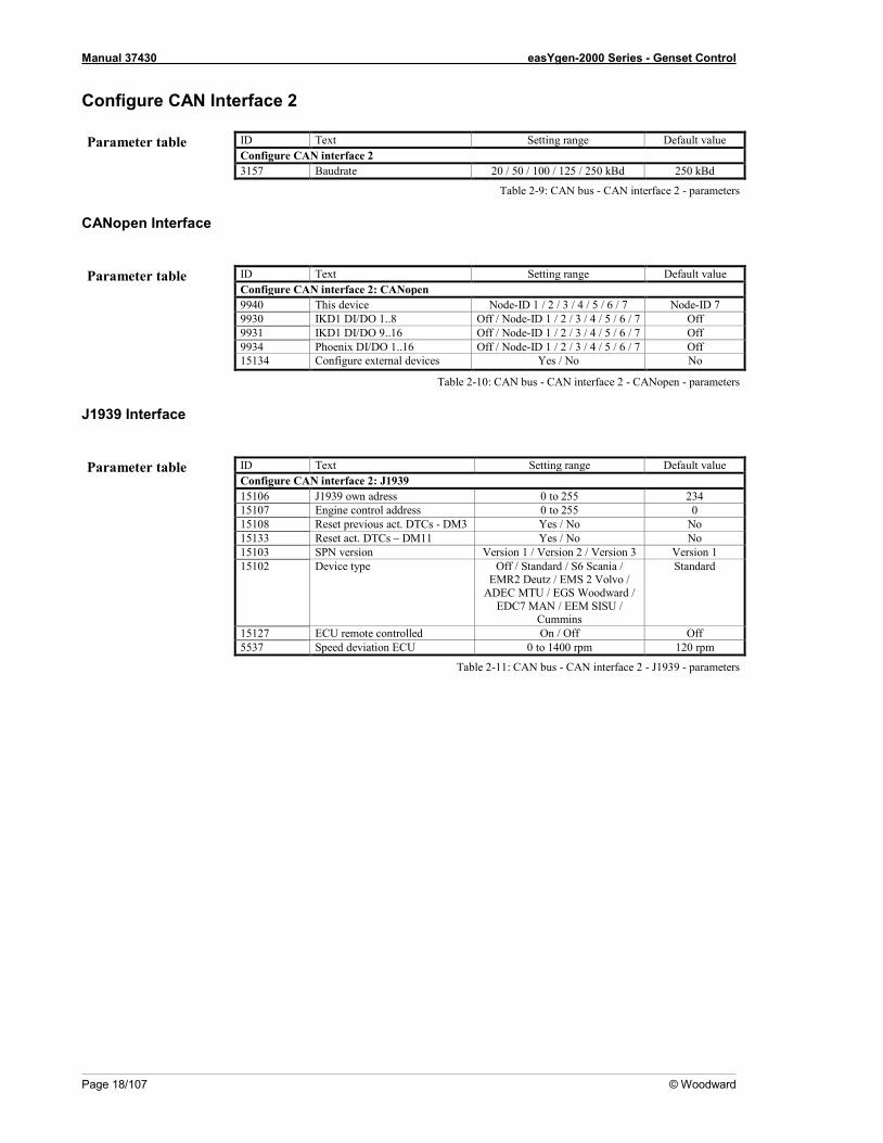
Configure CAN Interface 2 Parameter table ID Text Setting range Default value
Configure CAN interface 2 3157 Baudrate 20 / 50 / 100 / 125 / 250 kBd 250 kBd
Table 2-9: CAN bus - CAN interface 2 - parameters
CANopen Interface
Parameter table ID Text Setting range Default value
Configure CAN interface 2: CANopen 9940 This device Node-ID 1 / 2 / 3 / 4 / 5 / 6 / 7 Node-ID 7 9930 IKD1 DI/DO 1..8 Off / Node-ID 1 / 2 / 3 / 4 / 5 / 6 / 7 Off 9931 IKD1 DI/DO 9..16 Off / Node-ID 1 / 2 / 3 / 4 / 5 / 6 / 7 Off 9934 Phoenix DI/DO 1..16 Off / Node-ID 1 / 2 / 3 / 4 / 5 / 6 / 7 Off
15134 Configure external devices Yes / No No
Table 2-10: CAN bus - CAN interface 2 - CANopen - parameters
J1939 Interface
Parameter table ID Text Setting range Default value
Configure CAN interface 2: J1939 15106 J1939 own adress 0 to 255 234 15107 Engine control address 0 to 255 0 15108 Reset previous act. DTCs - DM3 Yes / No No 15133 Reset act. DTCs – DM11 Yes / No No 15103 SPN version Version 1 / Version 2 / Version 3 Version 1 15102 Device type Off / Standard / S6 Scania /
EMR2 Deutz / EMS 2 Volvo / ADEC MTU / EGS Woodward /
EDC7 MAN / EEM SISU / Cummins
Standard
15127 ECU remote controlled On / Off Off 5537 Speed deviation ECU 0 to 1400 rpm 120 rpm
Table 2-11: CAN bus - CAN interface 2 - J1939 - parameters
Manual 37430 easYgen-2000 Series - Genset Control
© Woodward Page 19/107
CAN Bus Load Sharing ≡≡≡≡≡≡≡≡≡≡≡≡≡≡≡≡≡≡≡≡≡≡≡≡≡
Multi-Master Principle It is important to know that the load share and load-dependent start/stop functionality is subject to a multi-master principle. This means that there is no dedicated master and slave function. Each easYgen decides for itself how it has to behave. The benefit is that there is no master control, which may cause a complete loss of this functionality in case it fails. Each control is also responsible for controlling common breakers like a mains circuit or generator group breaker.
Load Share Monitoring The easYgen provides two monitoring functions for load sharing (refer to the Configuration Manual 37427 for a detailed description of these functions):
Multi-Unit Parameter Alignment
The multi-unit parameter alignment functionality requires that the relevant parameters are all configured identi-cally at all participating units.
Multi-Unit Missing Members
The multi-unit missing members monitoring function checks whether all participating units are available (sending data on the load share line).
General Load Share Information The maximum number of participating easYgen-2000 Series devices for load sharing is 16. The CANopen bus load increases with the number of units participating in load sharing. The following parameters affect the bus load: • Number of CAN participants • Baud rate • Transfer rate of load share messages • Visualization
We recommend to consider whether all data has to be sent on the CAN bus when planning the CAN bus. It is also possible to send visualization data via RS-485 for example.
NOTE Refer to the Application Manual 37429 for a list of example configurations of different load sharing ap-plications.
Manual 37430 easYgen-2000 Series - Genset Control
Page 20/107 © Woodward
Measures for Reducing the Bus Load
If you need to reduce the bus load of the load share CAN bus, the following measured may be used: • Increase the baud rate (parameter 3156) under consideration of the bus length (refer to Installation Ma-
nual 37426) • Reduce the transfer rate of the load share message (parameter 9921) • Reduce the transfer rate of the visualization message, i.e. the event timer (parameter 9604) • Disable the transmission visualization data on the CAN bus and use the RS-485 interface to transmit visuali-
zation data • Disable SYNC message (parameter 9100) and/or TIME message (parameter 9101) and/or the producer
heartbeat time SYNC message (parameter 9120), if possible
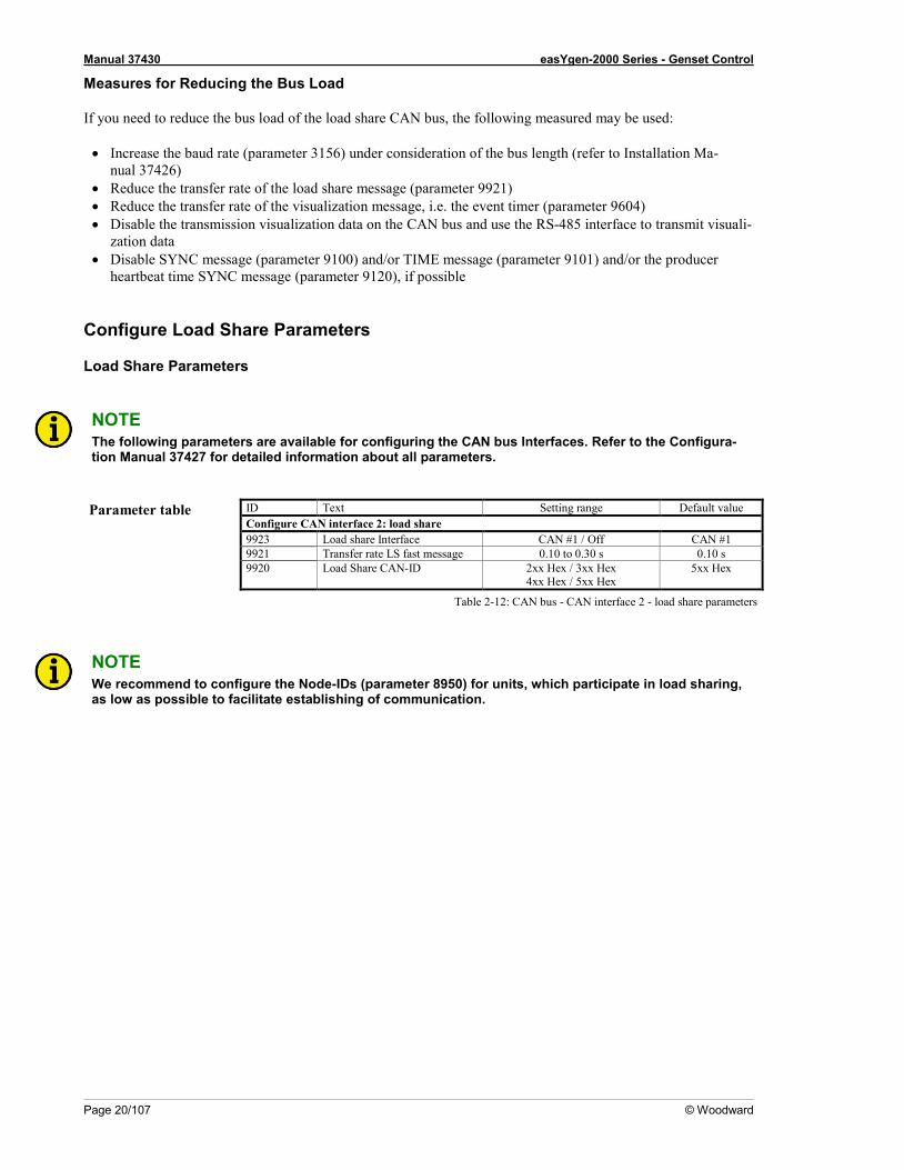
Configure Load Share Parameters
Load Share Parameters
NOTE The following parameters are available for configuring the CAN bus Interfaces. Refer to the Configura-tion Manual 37427 for detailed information about all parameters.
Parameter table ID Text Setting range Default value
Configure CAN interface 2: load share 9923 Load share Interface CAN #1 / Off CAN #1 9921 Transfer rate LS fast message 0.10 to 0.30 s 0.10 s 9920 Load Share CAN-ID 2xx Hex / 3xx Hex
4xx Hex / 5xx Hex 5xx Hex
Table 2-12: CAN bus - CAN interface 2 - load share parameters
NOTE We recommend to configure the Node-IDs (parameter 8950) for units, which participate in load sharing, as low as possible to facilitate establishing of communication.
Manual 37430 easYgen-2000 Series - Genset Control
© Woodward Page 21/107
Definition of CANopen Protocol Descriptions ≡≡≡≡≡≡≡≡≡≡≡≡≡≡≡≡≡≡≡≡≡≡≡≡≡≡≡≡≡≡≡≡≡≡
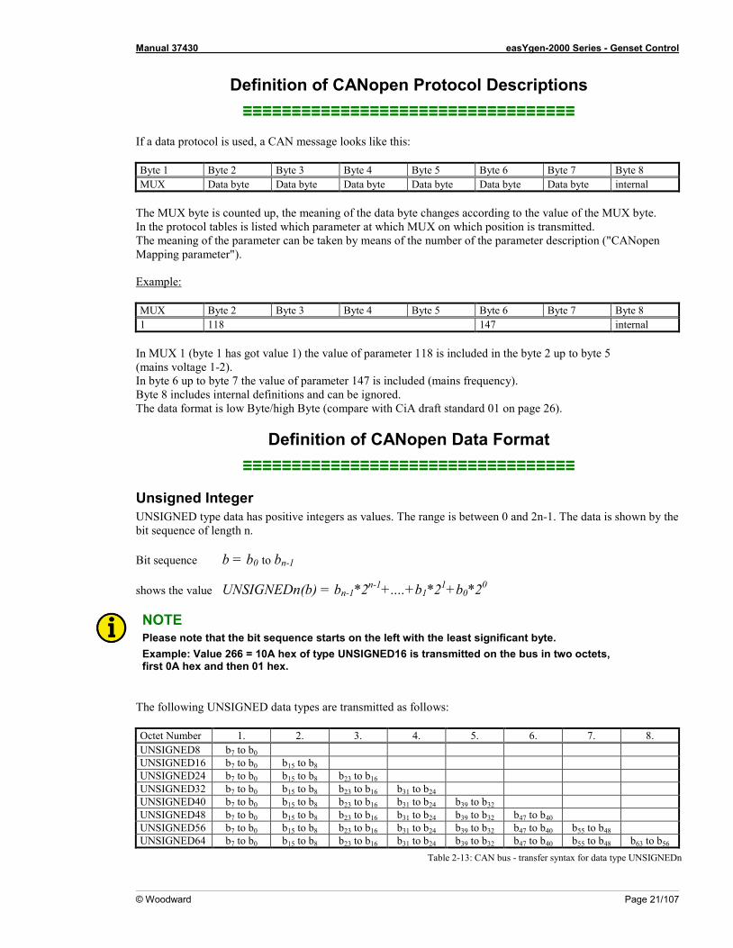
If a data protocol is used, a CAN message looks like this: Byte 1 Byte 2 Byte 3 Byte 4 Byte 5 Byte 6 Byte 7 Byte 8 MUX Data byte Data byte Data byte Data byte Data byte Data byte internal
The MUX byte is counted up, the meaning of the data byte changes according to the value of the MUX byte. In the protocol tables is listed which parameter at which MUX on which position is transmitted. The meaning of the parameter can be taken by means of the number of the parameter description ("CANopen Mapping parameter"). Example: MUX Byte 2 Byte 3 Byte 4 Byte 5 Byte 6 Byte 7 Byte 8 1 118 147 internal
In MUX 1 (byte 1 has got value 1) the value of parameter 118 is included in the byte 2 up to byte 5 (mains voltage 1-2). In byte 6 up to byte 7 the value of parameter 147 is included (mains frequency). Byte 8 includes internal definitions and can be ignored. The data format is low Byte/high Byte (compare with CiA draft standard 01 on page 26).
Definition of CANopen Data Format ≡≡≡≡≡≡≡≡≡≡≡≡≡≡≡≡≡≡≡≡≡≡≡≡≡≡≡≡≡≡≡≡≡≡
Unsigned Integer UNSIGNED type data has positive integers as values. The range is between 0 and 2n-1. The data is shown by the bit sequence of length n. Bit sequence b = b0 to bn-1 shows the value UNSIGNEDn(b) = bn-1*2n-1+....+b1*21+b0*20
NOTE Please note that the bit sequence starts on the left with the least significant byte. Example: Value 266 = 10A hex of type UNSIGNED16 is transmitted on the bus in two octets, first 0A hex and then 01 hex.
The following UNSIGNED data types are transmitted as follows: Octet Number 1. 2. 3. 4. 5. 6. 7. 8. UNSIGNED8 b7 to b0 UNSIGNED16 b7 to b0 b15 to b8 UNSIGNED24 b7 to b0 b15 to b8 b23 to b16 UNSIGNED32 b7 to b0 b15 to b8 b23 to b16 b31 to b24 UNSIGNED40 b7 to b0 b15 to b8 b23 to b16 b31 to b24 b39 to b32 UNSIGNED48 b7 to b0 b15 to b8 b23 to b16 b31 to b24 b39 to b32 b47 to b40 UNSIGNED56 b7 to b0 b15 to b8 b23 to b16 b31 to b24 b39 to b32 b47 to b40 b55 to b48 UNSIGNED64 b7 to b0 b15 to b8 b23 to b16 b31 to b24 b39 to b32 b47 to b40 b55 to b48 b63 to b56
Table 2-13: CAN bus - transfer syntax for data type UNSIGNEDn
Manual 37430 easYgen-2000 Series - Genset Control
Page 22/107 © Woodward
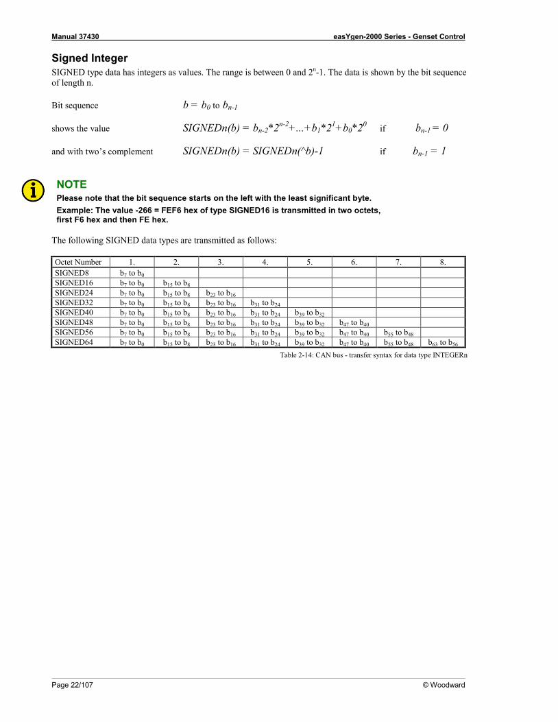
Signed Integer SIGNED type data has integers as values. The range is between 0 and 2n-1. The data is shown by the bit sequence of length n. Bit sequence b = b0 to bn-1 shows the value SIGNEDn(b) = bn-2*2n-2+...+b1*21+b0*20 if bn-1 = 0 and with two’s complement SIGNEDn(b) = SIGNEDn(^b)-1 if bn-1 = 1
NOTE Please note that the bit sequence starts on the left with the least significant byte. Example: The value -266 = FEF6 hex of type SIGNED16 is transmitted in two octets, first F6 hex and then FE hex.
The following SIGNED data types are transmitted as follows: Octet Number 1. 2. 3. 4. 5. 6. 7. 8. SIGNED8 b7 to b0 SIGNED16 b7 to b0 b15 to b8 SIGNED24 b7 to b0 b15 to b8 b23 to b16 SIGNED32 b7 to b0 b15 to b8 b23 to b16 b31 to b24 SIGNED40 b7 to b0 b15 to b8 b23 to b16 b31 to b24 b39 to b32 SIGNED48 b7 to b0 b15 to b8 b23 to b16 b31 to b24 b39 to b32 b47 to b40 SIGNED56 b7 to b0 b15 to b8 b23 to b16 b31 to b24 b39 to b32 b47 to b40 b55 to b48 SIGNED64 b7 to b0 b15 to b8 b23 to b16 b31 to b24 b39 to b32 b47 to b40 b55 to b48 b63 to b56
Table 2-14: CAN bus - transfer syntax for data type INTEGERn

Manual 37430 easYgen-2000 Series - Genset Control
© Woodward Page 23/107
J1939 Protocol Display Messages ≡≡≡≡≡≡≡≡≡≡≡≡≡≡≡≡≡≡≡≡≡≡≡≡≡
Messages of a device (for example an ECU) are received on the CAN bus according to J1939 protocol and are shown on the display. This function can be used via the CAN interface parallel to the CANopen protocol or to ToolKit. The Baud rate is similar for all devices connected to the CAN bus independent of the selected protocol.
Displayed Messages
DM1/DM2
The first 10 active alarm messages (Active Diagnostic Trouble Codes - DM1) and the first 10 unacknowledged alarm messages (Previously Active Diagnostic Trouble Codes - DM2) with SPN, FMI, and OC are displayed. The state of the lamps (amber/red) is always displayed. SPN (= Suspect Parameter Number) indicates the measuring value that the alarm code is referring (e.g. SPN = 100 corresponds to oil pressure). FMI (= Failure Mode Indicator) specifies the alarm more precisely (e.g. FMI = 3 means: value is valid but higher than the standard value.) OC: (Occurrence Count) indicates how often an alarm occurred. IF OC = 0, no alarm is present PGN (= Parameter Group Number) defines a particular combination of SPNs. Refer to the J1939 specification for a list of all SPNs.
Standard Messages
SPN PGN Description Resol. Data range J1939 Index Display with de-fective sensor
Display with missing sensor
52 65262 Engine intercooler temperature 1 °C -40 to 210 °C 15217 32766 °C 32767 °C 91 61443 Throttle position 0.1 % 0 to 100 % 15207 3276.6 % 3276.7 % 92 61443 Load at current speed 1 % 0 to 250 % 15208 32766 % 32767 % 94 65263 Fuel delivery pressure 1 kPa 0 to 1000 kPa 15218 32766 kPa 32767 kPa 95 65276 Fuel filter difference pressure 1 kPa 0 to 500 kPa 15219 32766 kPa 32767 kPa 98 65263 Engine oil level 0.1 % 0 to 100 % 15210 3276.6 % 3276.7 % 100 65263 Engine oil pressure 1 kPa 0 to 1000 kPa 15205 32766 kPa 32767 kPa 101 65263 Crankcase pressure 1 kPa -250 to 251 kPa 15220 32766 kPa 32767 kPa 102 65270 Boost pressure 1 kPa 0 to 500 kPa 15214 32766 kPa 32767 kPa 105 65270 Intake manifold temperature 1 °C -40 to 210 °C 15215 32766 °C 32767 °C 106 65270 Turbo air inlet pressure 1 kPa 0 to 500 kPa 15221 32766 kPa 32767 kPa 107 65270 Air filter 1 difference pressure 0.01 kPa 0 to 12.5 kPa 15222 327.66 kPa 327.67 kPa 108 65269 Barometric pressure 0.1 kPa 0 to 125 kPa 15212 3276.6 kPa 3276.7 kPa 109 65263 Coolant pressure 1 kPa 0 to 500 kPa 15223 32766 kPa 32767 kPa 110 65262 Engine coolant temperature 1 °C -40 to 210 °C 15202 32766 °C 32767 °C 111 65263 Coolant level 0.1 % 0 to 100 % 15206 3276.6 % 3276.7 % 127 65272 Transmission oil pressure 1 kPa 0 to 4000 kPa 15224 32766 kPa 32767 kPa 157 65243 Fuel rail pressure 0.1 MPa 0 to 251 Mpa 15225 3276.6 MPa 3276.7 MPa 171 65269 Ambient air temperature 0.1 °C -273 to 1735 °C 15226 3276.6 °C 3276.7 °C 172 65269 Air inlet temperature 1 °C -40 to 210 °C 15213 32766 °C 32767 °C 173 65270 Exhaust gas temperature 0.1 °C -273 to 1735 °C 15216 3276.6 °C 3276.7 °C 174 65262 Fuel temperature 1 °C -40 to 210 °C 15203 32766 °C 32767 °C 175 65262 Engine oil temperature 0.1 °C -273 to 1735 °C 15309 3276.6 °C 3276.7 °C 176 65262 Turbo oil temperature 0.1 °C -273 to 1735 °C 15227 3276.6 °C 3276.7 °C 177 65272 Transmission oil temperature 0.1 °C -273 to 1735 °C 15228 3276.6 °C 3276.7 °C 183 65266 Fuel rate 0.1 l/h 0 to 3212.75 l/h 15307 3276.6 L/h 3276.7 L/h 190 61444 Engine speed 1 rpm 0 to 8031.875 rpm 15308 32766 rpm 32767 rpm 247 65253 Total engine hours 1 1 h 0 to 210554060 h 15201 4294967294 h 4294967295 h 441 65164 Auxiliary temperature 1 1 °C -40 to 210 °C 15229 32766 °C 32767 °C 442 65164 Auxiliary temperature 2 1 °C -40 to 210 °C 15230 32766 °C 32767 °C
Manual 37430 easYgen-2000 Series - Genset Control
Page 24/107 © Woodward
SPN PGN Description Resol. Data range J1939 Index Display with de-fective sensor
Display with missing sensor
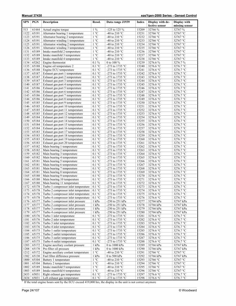
513 61444 Actual engine torque 1 % -125 to 125 % 15209 32766 % 32767 % 1122 65191 Alternator bearing 1 temperature 1 °C -40 to 210 °C 15231 32766 °C 32767 °C 1123 65191 Alternator bearing 2 temperature 1 °C -40 to 210 °C 15232 32766 °C 32767 °C 1124 65191 Alternator winding 1 temperature 1 °C -40 to 210 °C 15233 32766 °C 32767 °C 1125 65191 Alternator winding 2 temperature 1 °C -40 to 210 °C 15234 32766 °C 32767 °C 1126 65191 Alternator winding 3 temperature 1 °C -40 to 210 °C 15235 32766 °C 32767 °C 1131 65189 Intake manifold 2 temperature 1 °C -40 to 210 °C 15236 32766 °C 32767 °C 1132 65189 Intake manifold 3 temperature 1 °C -40 to 210 °C 15237 32766 °C 32767 °C 1133 65189 Intake manifold 4 temperature 1 °C -40 to 210 °C 15238 32766 °C 32767 °C 1134 65262 Engine thermostat 0.1 % 0 to 100 % 15239 3276.6 % 3276.7 % 1135 65188 Engine oil temperature 2 0.1 °C -273 to 1735 °C 15240 3276.6 °C 3276.7 °C 1136 65188 Engine ECU temperature 0.1 °C -273 to 1735 °C 15241 3276.6 °C 3276.7 °C 1137 65187 Exhaust gas port 1 temperature 0.1 °C -273 to 1735 °C 15242 3276.6 °C 3276.7 °C 1138 65187 Exhaust gas port 2 temperature 0.1 °C -273 to 1735 °C 15243 3276.6 °C 3276.7 °C 1139 65187 Exhaust gas port 3 temperature 0.1 °C -273 to 1735 °C 15244 3276.6 °C 3276.7 °C 1140 65187 Exhaust gas port 4 temperature 0.1 °C -273 to 1735 °C 15245 3276.6 °C 3276.7 °C 1141 65186 Exhaust gas port 5 temperature 0.1 °C -273 to 1735 °C 15246 3276.6 °C 3276.7 °C 1142 65186 Exhaust gas port 6 temperature 0.1 °C -273 to 1735 °C 15247 3276.6 °C 3276.7 °C 1143 65186 Exhaust gas port 7 temperature 0.1 °C -273 to 1735 °C 15248 3276.6 °C 3276.7 °C 1144 65186 Exhaust gas port 8 temperature 0.1 °C -273 to 1735 °C 15249 3276.6 °C 3276.7 °C 1145 65185 Exhaust gas port 9 temperature 0.1 °C -273 to 1735 °C 15250 3276.6 °C 3276.7 °C 1146 65185 Exhaust gas port 10 temperature 0.1 °C -273 to 1735 °C 15251 3276.6 °C 3276.7 °C 1147 65185 Exhaust gas port 11 temperature 0.1 °C -273 to 1735 °C 15252 3276.6 °C 3276.7 °C 1148 65185 Exhaust gas port 12 temperature 0.1 °C -273 to 1735 °C 15253 3276.6 °C 3276.7 °C 1149 65184 Exhaust gas port 13 temperature 0.1 °C -273 to 1735 °C 15254 3276.6 °C 3276.7 °C 1150 65184 Exhaust gas port 14 temperature 0.1 °C -273 to 1735 °C 15255 3276.6 °C 3276.7 °C 1151 65184 Exhaust gas port 15 temperature 0.1 °C -273 to 1735 °C 15256 3276.6 °C 3276.7 °C 1152 65184 Exhaust gas port 16 temperature 0.1 °C -273 to 1735 °C 15257 3276.6 °C 3276.7 °C 1153 65183 Exhaust gas port 17 temperature 0.1 °C -273 to 1735 °C 15258 3276.6 °C 3276.7 °C 1154 65183 Exhaust gas port 18 temperature 0.1 °C -273 to 1735 °C 15259 3276.6 °C 3276.7 °C 1155 65183 Exhaust gas port 19 temperature 0.1 °C -273 to 1735 °C 15260 3276.6 °C 3276.7 °C 1156 65183 Exhaust gas port 20 temperature 0.1 °C -273 to 1735 °C 15261 3276.6 °C 3276.7 °C 1157 65182 Main bearing 1 temperature 0.1 °C -273 to 1735 °C 15262 3276.6 °C 3276.7 °C 1158 65182 Main bearing 2 temperature 0.1 °C -273 to 1735 °C 15263 3276.6 °C 3276.7 °C 1159 65182 Main bearing 3 temperature 0.1 °C -273 to 1735 °C 15264 3276.6 °C 3276.7 °C 1160 65182 Main bearing 4 temperature 0.1 °C -273 to 1735 °C 15265 3276.6 °C 3276.7 °C 1161 65181 Main bearing 5 temperature 0.1 °C -273 to 1735 °C 15266 3276.6 °C 3276.7 °C 1162 65181 Main bearing 6 temperature 0.1 °C -273 to 1735 °C 15267 3276.6 °C 3276.7 °C 1163 65181 Main bearing 7 temperature 0.1 °C -273 to 1735 °C 15268 3276.6 °C 3276.7 °C 1164 65181 Main bearing 8 temperature 0.1 °C -273 to 1735 °C 15269 3276.6 °C 3276.7 °C 1165 65180 Main bearing 9 temperature 0.1 °C -273 to 1735 °C 15270 3276.6 °C 3276.7 °C 1166 65180 Main bearing 10 temperature 0.1 °C -273 to 1735 °C 15271 3276.6 °C 3276.7 °C 1167 65180 Main bearing 11 temperature 0.1 °C -273 to 1735 °C 15272 3276.6 °C 3276.7 °C 1172 65178 Turbo 1 compressor inlet temperature 0.1 °C -273 to 1735 °C 15273 3276.6 °C 3276.7 °C 1173 65178 Turbo 2 compressor inlet temperature 0.1 °C -273 to 1735 °C 15274 3276.6 °C 3276.7 °C 1174 65178 Turbo 3 compressor inlet temperature 0.1 °C -273 to 1735 °C 15275 3276.6 °C 3276.7 °C 1175 65178 Turbo 4 compressor inlet temperature 0.1 °C -273 to 1735 °C 15276 3276.6 °C 3276.7 °C 1176 65177 Turbo 1 compressor inlet pressure 1 kPa -250 to 251 kPa 15277 32766 kPa 32767 kPa 1177 65177 Turbo 2 compressor inlet pressure 1 kPa -250 to 251 kPa 15278 32766 kPa 32767 kPa 1178 65177 Turbo 3 compressor inlet pressure 1 kPa -250 to 251 kPa 15279 32766 kPa 32767 kPa 1179 65177 Turbo 4 compressor inlet pressure 1 kPa -250 to 251 kPa 15280 32766 kPa 32767 kPa 1180 65176 Turbo 1 inlet temperature 0.1 °C -273 to 1735 °C 15281 3276.6 °C 3276.7 °C 1181 65176 Turbo 2 inlet temperature 0.1 °C -273 to 1735 °C 15282 3276.6 °C 3276.7 °C 1182 65176 Turbo 3 inlet temperature 0.1 °C -273 to 1735 °C 15283 3276.6 °C 3276.7 °C 1183 65176 Turbo 4 inlet temperature 0.1 °C -273 to 1735 °C 15284 3276.6 °C 3276.7 °C 1184 65175 Turbo 1 outlet temperature 0.1 °C -273 to 1735 °C 15285 3276.6 °C 3276.7 °C 1185 65175 Turbo 2 outlet temperature 0.1 °C -273 to 1735 °C 15286 3276.6 °C 3276.7 °C 1186 65175 Turbo 3 outlet temperature 0.1 °C -273 to 1735 °C 15287 3276.6 °C 3276.7 °C 1187 65175 Turbo 4 outlet temperature 0.1 °C -273 to 1735 °C 15288 3276.6 °C 3276.7 °C 1203 65172 Engine auxiliary coolant pressure 1 kPa 0 to 1000 kPa 15289 32766 kPa 32767 kPa 1208 65170 Pre-filter oil pressure 1 kPa 0 to 1000 kPa 15290 32766 kPa 32767 kPa 1212 65172 Engine auxiliary coolant temperature 1 °C -40 to 210 °C 15291 32766 °C 32767 °C 1382 65130 Fuel filter difference pressure 1 kPa 0 to 500 kPa 15292 32766 kPa 32767 kPa 1800 65104 Battery 1 temperature 1 °C -40 to 210 °C 15293 32766 °C 32767 °C 1801 65104 Battery 2 temperature 1 °C -40 to 210 °C 15294 32766 °C 32767 °C 1802 65189 Intake manifold 5 temperature 1 °C -40 to 210 °C 15295 32766 °C 32767 °C 1803 65189 Intake manifold 6 temperature 1 °C -40 to 210 °C 15296 32766 °C 32767 °C 2433 65031 Right exhaust gas temperature 0.1 °C -273 to 1735 °C 15297 3276.6 °C 3276.7 °C 2434 65031 Left exhaust gas temperature 0.1 °C -273 to 1735 °C 15298 3276.6 °C 3276.7 °C
1 If the total engine hours sent by the ECU exceed 419,000 hrs, the display in the unit is not correct anymore
Manual 37430 easYgen-2000 Series - Genset Control
© Woodward Page 25/107
Table 2-15: J1939 protocol - standard messages
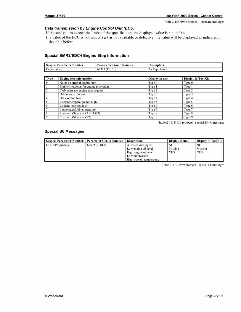
Data transmission by Engine Control Unit (ECU) If the sent values exceed the limits of the specification, the displayed value is not defined. If a value of the ECU is not sent or sent as not available or defective, the value will be displayed as indicated in
the table before.
Special EMR2/EDC4 Engine Stop Information
Suspect Parameter Number Parameter Group Number Description Engine stop 65301 (FF15h) As Type 0 to 9
Type Engine stop information Display in unit Display in ToolKit 0 No or no special engine stop Type 0 Type 0 1 Engine shutdown for engine protection Type 1 Type 1 2 CAN message engine stop request Type 2 Type 2 3 Oil pressure too low Type 3 Type 3 4 Oil level too low Type 4 Type 4 5 Coolant temperature too high Type 5 Type 5 6 Coolant level too low Type 6 Type 6 7 Intake manifold temperature Type 7 Type 7 8 Reserved (Stop via SAE-J1587) Type 8 Type 8 9 Reserved (Stop via VP2) Type 9 Type 9
Table 2-16: J1939 protocol - special EMR messages
Special S6 Messages
Suspect Parameter Number Parameter Group Number Description Display in unit Display in ToolKit DLN2-Proprietary 65409 (FF81h) Assessed messages:
Low engine oil level High engine oil level Low oil pressure High coolant temperature
NO Missing YES
NO Missing YES
Table 2-17: J1939 protocol - special S6 messages
Manual 37430 easYgen-2000 Series - Genset Control
Page 26/107 © Woodward
Remote Control via CAN ≡≡≡≡≡≡≡≡≡≡≡≡≡≡≡≡≡≡≡≡≡≡≡≡≡
Remote Start/Stop and Acknowledgement Refer to the Performing Remote Start/Stop and Acknowledgement section in the Special Application Examples section of the application manual 37429 for detailed information. The easYgen may be started, stopped, or acknowledged with CAN/Modbus. Therefore, two logical command va-riables have to be configured with the LogicsManager: 04.13 Remote request 04.14 Remote acknowledge Two different methods to perform a remote start/stop/acknowledgement are detailed in the following. These are "Remote start/stop/acknowledgement via RPDO" and "Remote start/stop/acknowledgement via default SDO communication channel". The advantages and the disadvantages of these two methods are as follows:
Comparison of the Two Methods
Start/Stop/Acknowledgement via RPDO • Classical communication for CANopen devices • One message • No validation of the received answer • Only working in operational mode
Start/Stop/Acknowledgement via Default SDO Communication Channel • Configuration process • Two messages • Validation answer, if message has been received by the unit • May take longer in case of communication with two messages
Remote Start/Stop/Acknowledgement via RPDO
Configuration of CAN Interface 1 Be sure to enable CAN-Open Master (parameter 8993) if there is no PLC taking over the master function. Navigate to the "CAN interface 1 config." screen by pressing the following softkeys in this sequence: Parameter -> Configuration -> Interfaces config. -> CAN interface config. -> CAN interface 1 config.
Manual 37430 easYgen-2000 Series - Genset Control
© Woodward Page 27/107
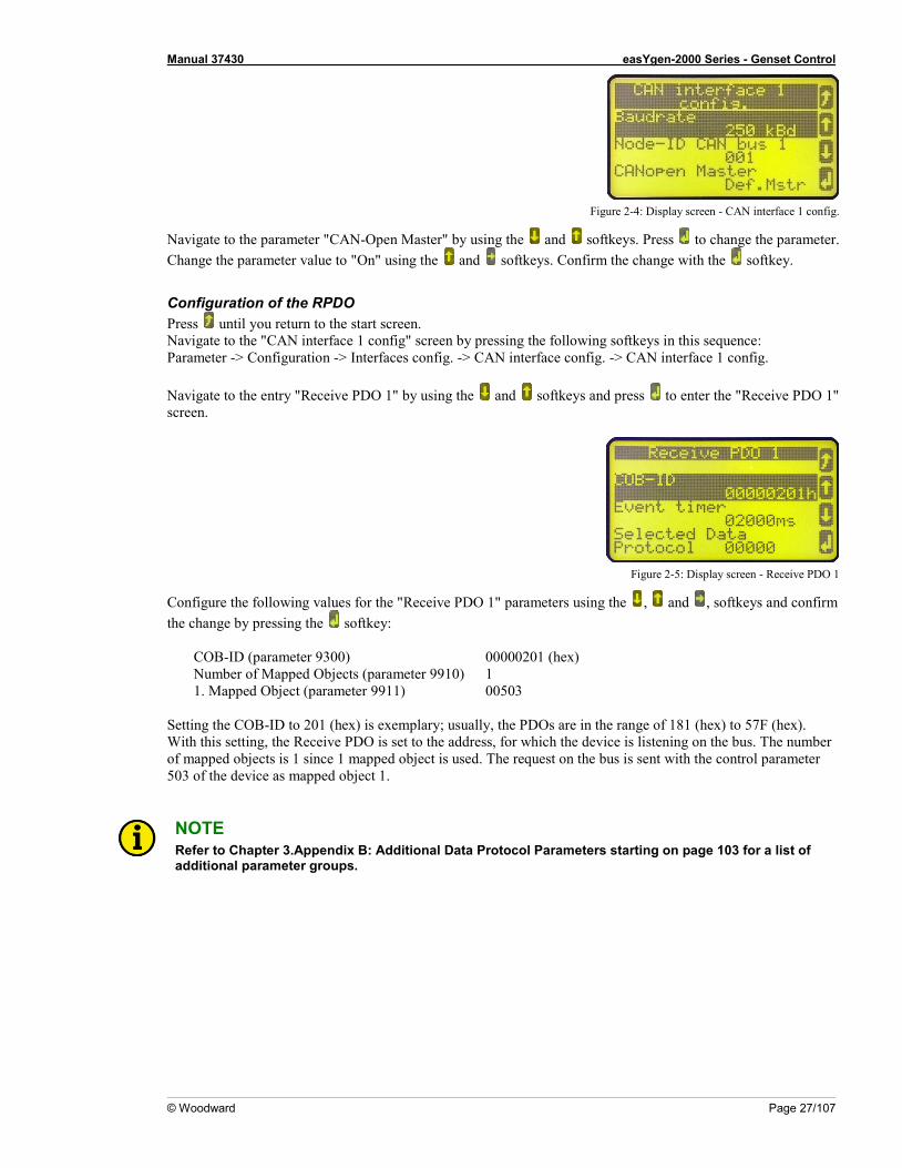
Figure 2-4: Display screen - CAN interface 1 config.
Navigate to the parameter "CAN-Open Master" by using the and softkeys. Press to change the parameter. Change the parameter value to "On" using the and softkeys. Confirm the change with the softkey.
Configuration of the RPDO Press until you return to the start screen. Navigate to the "CAN interface 1 config" screen by pressing the following softkeys in this sequence: Parameter -> Configuration -> Interfaces config. -> CAN interface config. -> CAN interface 1 config. Navigate to the entry "Receive PDO 1" by using the and softkeys and press to enter the "Receive PDO 1" screen.
Figure 2-5: Display screen - Receive PDO 1
Configure the following values for the "Receive PDO 1" parameters using the , and , softkeys and confirm the change by pressing the softkey:
COB-ID (parameter 9300) 00000201 (hex) Number of Mapped Objects (parameter 9910) 1 1. Mapped Object (parameter 9911) 00503
Setting the COB-ID to 201 (hex) is exemplary; usually, the PDOs are in the range of 181 (hex) to 57F (hex). With this setting, the Receive PDO is set to the address, for which the device is listening on the bus. The number of mapped objects is 1 since 1 mapped object is used. The request on the bus is sent with the control parameter 503 of the device as mapped object 1.
NOTE Refer to Chapter 3.Appendix B: Additional Data Protocol Parameters starting on page 103 for a list of additional parameter groups.
Manual 37430 easYgen-2000 Series - Genset Control
Page 28/107 © Woodward
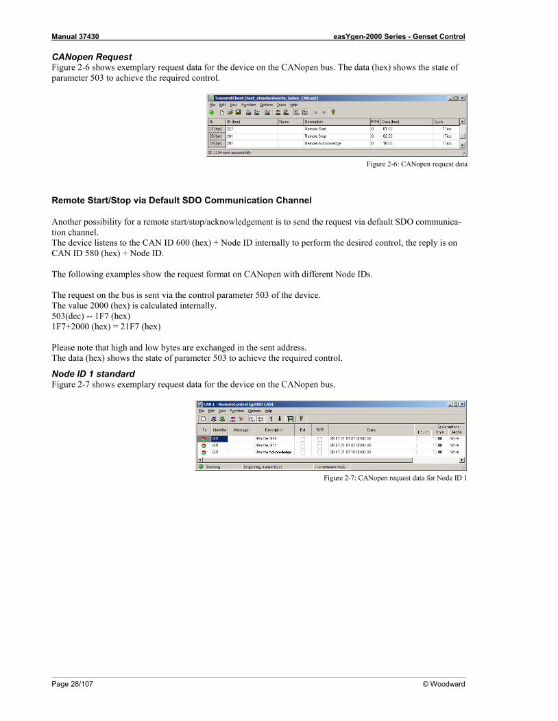
CANopen Request Figure 2-6 shows exemplary request data for the device on the CANopen bus. The data (hex) shows the state of parameter 503 to achieve the required control.
Figure 2-6: CANopen request data
Remote Start/Stop via Default SDO Communication Channel
Another possibility for a remote start/stop/acknowledgement is to send the request via default SDO communica-tion channel. The device listens to the CAN ID 600 (hex) + Node ID internally to perform the desired control, the reply is on CAN ID 580 (hex) + Node ID. The following examples show the request format on CANopen with different Node IDs. The request on the bus is sent via the control parameter 503 of the device. The value 2000 (hex) is calculated internally. 503(dec) -- 1F7 (hex) 1F7+2000 (hex) = 21F7 (hex) Please note that high and low bytes are exchanged in the sent address. The data (hex) shows the state of parameter 503 to achieve the required control.
Node ID 1 standard Figure 2-7 shows exemplary request data for the device on the CANopen bus.
Figure 2-7: CANopen request data for Node ID 1
Manual 37430 easYgen-2000 Series - Genset Control
© Woodward Page 29/107
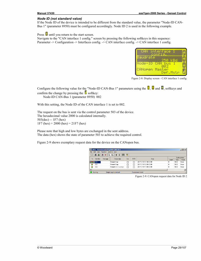
Node ID (not standard value) If the Node ID of the device is intended to be different from the standard value, the parameter "Node-ID CAN-Bus 1" (parameter 8950) must be configured accordingly. Node ID 2 is used in the following example. Press until you return to the start screen. Navigate to the "CAN interface 1 config." screen by pressing the following softkeys in this sequence: Parameter -> Configuration -> Interfaces config. -> CAN interface config. -> CAN interface 1 config.
Figure 2-8: Display screen - CAN interface 1 config.
Configure the following value for the "Node-ID CAN-Bus 1" parameters using the , and , softkeys and confirm the change by pressing the softkey:
Node-ID CAN-Bus 1 (parameter 8950) 002 With this setting, the Node ID of the CAN interface 1 is set to 002. The request on the bus is sent via the control parameter 503 of the device. The hexadecimal value 2000 is calculated internally. 503(dec) -- 1F7 (hex) 1F7 (hex) + 2000 (hex) = 21F7 (hex) Please note that high and low bytes are exchanged in the sent address. The data (hex) shows the state of parameter 503 to achieve the required control. Figure 2-9 shows exemplary request data for the device on the CANopen bus.
Figure 2-9: CANopen request data for Node ID 2
Manual 37430 easYgen-2000 Series - Genset Control
Page 30/107 © Woodward
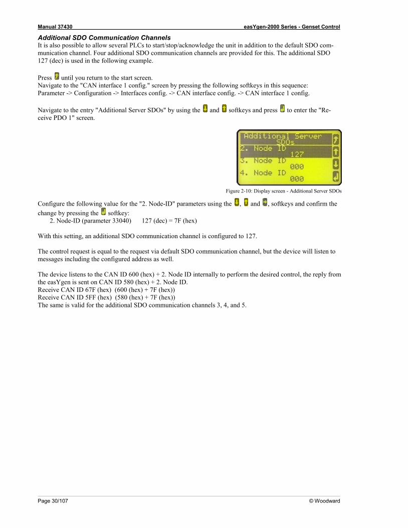
Additional SDO Communication Channels It is also possible to allow several PLCs to start/stop/acknowledge the unit in addition to the default SDO com-munication channel. Four additional SDO communication channels are provided for this. The additional SDO 127 (dec) is used in the following example. Press until you return to the start screen. Navigate to the "CAN interface 1 config." screen by pressing the following softkeys in this sequence: Parameter -> Configuration -> Interfaces config. -> CAN interface config. -> CAN interface 1 config. Navigate to the entry "Additional Server SDOs" by using the and softkeys and press to enter the "Re-ceive PDO 1" screen.
Figure 2-10: Display screen - Additional Server SDOs
Configure the following value for the "2. Node-ID" parameters using the , and , softkeys and confirm the change by pressing the softkey:
2. Node-ID (parameter 33040) 127 (dec) = 7F (hex) With this setting, an additional SDO communication channel is configured to 127. The control request is equal to the request via default SDO communication channel, but the device will listen to messages including the configured address as well. The device listens to the CAN ID 600 (hex) + 2. Node ID internally to perform the desired control, the reply from the easYgen is sent on CAN ID 580 (hex) + 2. Node ID. Receive CAN ID 67F (hex) (600 (hex) + 7F (hex)) Receive CAN ID 5FF (hex) (580 (hex) + 7F (hex)) The same is valid for the additional SDO communication channels 3, 4, and 5.
Manual 37430 easYgen-2000 Series - Genset Control
© Woodward Page 31/107
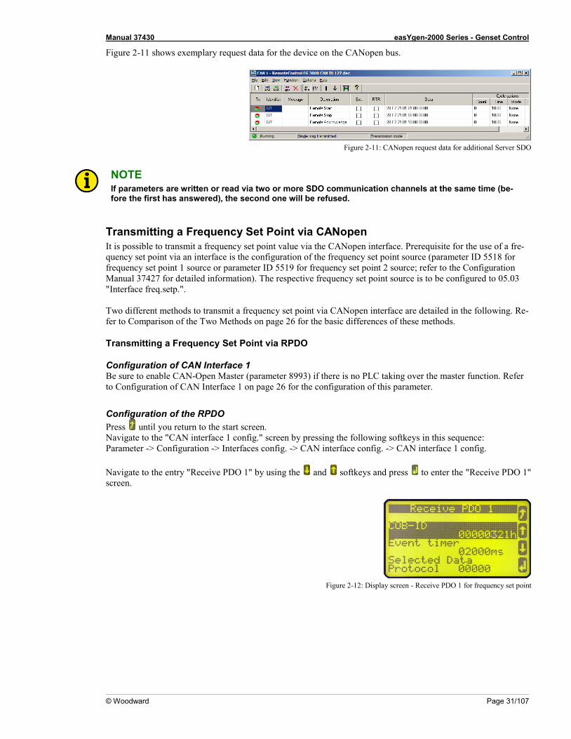
Figure 2-11 shows exemplary request data for the device on the CANopen bus.
Figure 2-11: CANopen request data for additional Server SDO
NOTE If parameters are written or read via two or more SDO communication channels at the same time (be-fore the first has answered), the second one will be refused.
Transmitting a Frequency Set Point via CANopen It is possible to transmit a frequency set point value via the CANopen interface. Prerequisite for the use of a fre-quency set point via an interface is the configuration of the frequency set point source (parameter ID 5518 for frequency set point 1 source or parameter ID 5519 for frequency set point 2 source; refer to the Configuration Manual 37427 for detailed information). The respective frequency set point source is to be configured to 05.03 "Interface freq.setp.". Two different methods to transmit a frequency set point via CANopen interface are detailed in the following. Re-fer to Comparison of the Two Methods on page 26 for the basic differences of these methods.
Transmitting a Frequency Set Point via RPDO
Configuration of CAN Interface 1 Be sure to enable CAN-Open Master (parameter 8993) if there is no PLC taking over the master function. Refer to Configuration of CAN Interface 1 on page 26 for the configuration of this parameter.
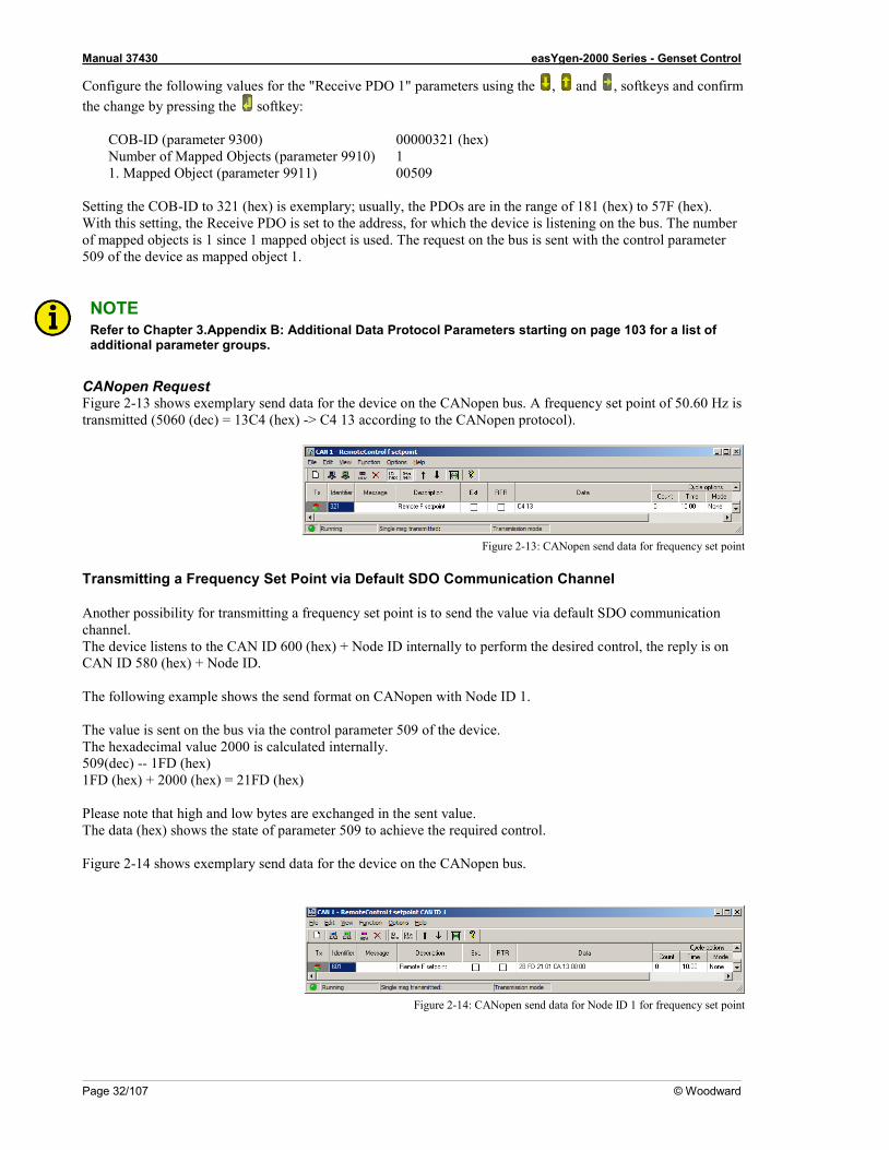
Configuration of the RPDO Press until you return to the start screen. Navigate to the "CAN interface 1 config." screen by pressing the following softkeys in this sequence: Parameter -> Configuration -> Interfaces config. -> CAN interface config. -> CAN interface 1 config. Navigate to the entry "Receive PDO 1" by using the and softkeys and press to enter the "Receive PDO 1" screen.
Figure 2-12: Display screen - Receive PDO 1 for frequency set point
Manual 37430 easYgen-2000 Series - Genset Control
Page 32/107 © Woodward
Configure the following values for the "Receive PDO 1" parameters using the , and , softkeys and confirm the change by pressing the softkey:
COB-ID (parameter 9300) 00000321 (hex) Number of Mapped Objects (parameter 9910) 1 1. Mapped Object (parameter 9911) 00509
Setting the COB-ID to 321 (hex) is exemplary; usually, the PDOs are in the range of 181 (hex) to 57F (hex). With this setting, the Receive PDO is set to the address, for which the device is listening on the bus. The number of mapped objects is 1 since 1 mapped object is used. The request on the bus is sent with the control parameter 509 of the device as mapped object 1.
NOTE Refer to Chapter 3.Appendix B: Additional Data Protocol Parameters starting on page 103 for a list of additional parameter groups.
CANopen Request Figure 2-13 shows exemplary send data for the device on the CANopen bus. A frequency set point of 50.60 Hz is transmitted (5060 (dec) = 13C4 (hex) -> C4 13 according to the CANopen protocol).
Figure 2-13: CANopen send data for frequency set point
Transmitting a Frequency Set Point via Default SDO Communication Channel
Another possibility for transmitting a frequency set point is to send the value via default SDO communication channel. The device listens to the CAN ID 600 (hex) + Node ID internally to perform the desired control, the reply is on CAN ID 580 (hex) + Node ID. The following example shows the send format on CANopen with Node ID 1. The value is sent on the bus via the control parameter 509 of the device. The hexadecimal value 2000 is calculated internally. 509(dec) -- 1FD (hex) 1FD (hex) + 2000 (hex) = 21FD (hex) Please note that high and low bytes are exchanged in the sent value. The data (hex) shows the state of parameter 509 to achieve the required control. Figure 2-14 shows exemplary send data for the device on the CANopen bus.
Figure 2-14: CANopen send data for Node ID 1 for frequency set point
Manual 37430 easYgen-2000 Series - Genset Control
© Woodward Page 33/107
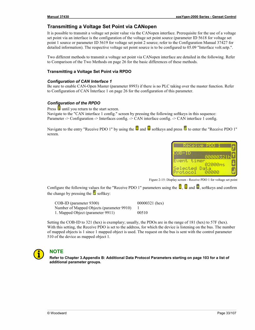
Transmitting a Voltage Set Point via CANopen It is possible to transmit a voltage set point value via the CANopen interface. Prerequisite for the use of a voltage set point via an interface is the configuration of the voltage set point source (parameter ID 5618 for voltage set point 1 source or parameter ID 5619 for voltage set point 2 source; refer to the Configuration Manual 37427 for detailed information). The respective voltage set point source is to be configured to 05.09 "Interface volt.setp.". Two different methods to transmit a voltage set point via CANopen interface are detailed in the following. Refer to Comparison of the Two Methods on page 26 for the basic differences of these methods.
Transmitting a Voltage Set Point via RPDO
Configuration of CAN Interface 1 Be sure to enable CAN-Open Master (parameter 8993) if there is no PLC taking over the master function. Refer to Configuration of CAN Interface 1 on page 26 for the configuration of this parameter.
Configuration of the RPDO Press until you return to the start screen. Navigate to the "CAN interface 1 config." screen by pressing the following softkeys in this sequence: Parameter -> Configuration -> Interfaces config. -> CAN interface config. -> CAN interface 1 config. Navigate to the entry "Receive PDO 1" by using the and softkeys and press to enter the "Receive PDO 1" screen.
Figure 2-15: Display screen - Receive PDO 1 for voltage set point
Configure the following values for the "Receive PDO 1" parameters using the , and , softkeys and confirm the change by pressing the softkey:
COB-ID (parameter 9300) 00000321 (hex) Number of Mapped Objects (parameter 9910) 1 1. Mapped Object (parameter 9911) 00510
Setting the COB-ID to 321 (hex) is exemplary; usually, the PDOs are in the range of 181 (hex) to 57F (hex). With this setting, the Receive PDO is set to the address, for which the device is listening on the bus. The number of mapped objects is 1 since 1 mapped object is used. The request on the bus is sent with the control parameter 510 of the device as mapped object 1.
NOTE Refer to Chapter 3.Appendix B: Additional Data Protocol Parameters starting on page 103 for a list of additional parameter groups.
Manual 37430 easYgen-2000 Series - Genset Control
Page 34/107 © Woodward
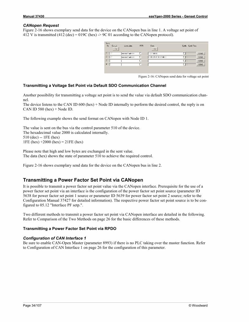
CANopen Request Figure 2-16 shows exemplary send data for the device on the CANopen bus in line 1. A voltage set point of 412 V is transmitted (412 (dec) = 019C (hex) -> 9C 01 according to the CANopen protocol).
Figure 2-16: CANopen send data for voltage set point
Transmitting a Voltage Set Point via Default SDO Communication Channel
Another possibility for transmitting a voltage set point is to send the value via default SDO communication chan-nel. The device listens to the CAN ID 600 (hex) + Node ID internally to perform the desired control, the reply is on CAN ID 580 (hex) + Node ID. The following example shows the send format on CANopen with Node ID 1. The value is sent on the bus via the control parameter 510 of the device. The hexadecimal value 2000 is calculated internally. 510 (dec) -- 1FE (hex) 1FE (hex) +2000 (hex) = 21FE (hex) Please note that high and low bytes are exchanged in the sent value. The data (hex) shows the state of parameter 510 to achieve the required control. Figure 2-16 shows exemplary send data for the device on the CANopen bus in line 2.
Transmitting a Power Factor Set Point via CANopen It is possible to transmit a power factor set point value via the CANopen interface. Prerequisite for the use of a power factor set point via an interface is the configuration of the power factor set point source (parameter ID 5638 for power factor set point 1 source or parameter ID 5639 for power factor set point 2 source; refer to the Configuration Manual 37427 for detailed information). The respective power factor set point source is to be con-figured to 05.12 "Interface PF setp.". Two different methods to transmit a power factor set point via CANopen interface are detailed in the following. Refer to Comparison of the Two Methods on page 26 for the basic differences of these methods.
Transmitting a Power Factor Set Point via RPDO
Configuration of CAN Interface 1 Be sure to enable CAN-Open Master (parameter 8993) if there is no PLC taking over the master function. Refer to Configuration of CAN Interface 1 on page 26 for the configuration of this parameter.
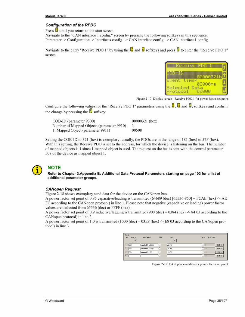
Manual 37430 easYgen-2000 Series - Genset Control
© Woodward Page 35/107
Configuration of the RPDO Press until you return to the start screen. Navigate to the "CAN interface 1 config." screen by pressing the following softkeys in this sequence: Parameter -> Configuration -> Interfaces config. -> CAN interface config. -> CAN interface 1 config. Navigate to the entry "Receive PDO 1" by using the and softkeys and press to enter the "Receive PDO 1" screen.
Figure 2-17: Display screen - Receive PDO 1 for power factor set point
Configure the following values for the "Receive PDO 1" parameters using the , and , softkeys and confirm the change by pressing the softkey:
COB-ID (parameter 9300) 00000321 (hex) Number of Mapped Objects (parameter 9910) 1 1. Mapped Object (parameter 9911) 00508
Setting the COB-ID to 321 (hex) is exemplary; usually, the PDOs are in the range of 181 (hex) to 57F (hex). With this setting, the Receive PDO is set to the address, for which the device is listening on the bus. The number of mapped objects is 1 since 1 mapped object is used. The request on the bus is sent with the control parameter 508 of the device as mapped object 1.
NOTE Refer to Chapter 3.Appendix B: Additional Data Protocol Parameters starting on page 103 for a list of additional parameter groups.
CANopen Request Figure 2-18 shows exemplary send data for the device on the CANopen bus. A power factor set point of 0.85 capacitive/leading is transmitted (64689 (dec) [65536-850] = FCAE (hex) -> AE FC according to the CANopen protocol) in line 1. Please note that negative (capacitive or leading) power factor values are deducted from 65536 (dec) or FFFF (hex). A power factor set point of 0.9 inductive/lagging is transmitted (900 (dec) = 0384 (hex) -> 84 03 according to the CANopen protocol) in line 2. A power factor set point of 1.0 is transmitted (1000 (dec) = 03E8 (hex) -> E8 03 according to the CANopen pro-tocol) in line 3.
Figure 2-18: CANopen send data for power factor set point

Manual 37430 easYgen-2000 Series - Genset Control
Page 36/107 © Woodward
Transmitting a Power Factor Set Point via Default SDO Communication Channel
Another possibility for transmitting a power factor set point is to send the value via default SDO communication channel. The device listens to the CAN ID 600 (hex) + Node ID internally to perform the desired control, the reply is on CAN ID 580 (hex) + Node ID. The following example shows the send format on CANopen with Node ID 1. Thevalue is sent on the bus via the control parameter 508 of the device. The hexadecimal value 2000 is calculated internally. 508 (dec) -- 1FC (hex) 1FC (hex) + 2000 (hex) = 21FC (hex) Please note that high and low bytes are exchanged in the sent value. The data (hex) shows the state of parameter 508 to achieve the required control. Figure 2-19 shows exemplary send data for the device on the CANopen bus.
Figure 2-19: CANopen send data for Node ID 1 for power factor set point
Transmitting a Power Set Point via CANopen It is possible to transmit a power set point value via the CANopen interface. Prerequisite for the use of a power set point via an interface is the configuration of the power set point source (parameter ID 5539 for power set point 1 source or parameter ID 5540 for power set point 2 source; refer to the Configuration Manual 37427 for detailed information). The respective power set point source is to be configured to 05.06 "Interface pow. setp.". Please note that the type of the power set point (Constant, Import, or Export) must also be defined (parameter ID 5526 for load set point 1 or parameter ID 5527 for load set point 2). Two different methods to transmit a voltage set point via CANopen interface are detailed in the following. Refer to Comparison of the Two Methods on page 26 for the basic differences of these methods.
Transmitting a Power Set Point via RPDO
Configuration of CAN Interface 1 Be sure to enable CAN-Open Master (parameter 8993) if there is no PLC taking over the master function. Refer to Configuration of CAN Interface 1 on page 26 for the configuration of this parameter.
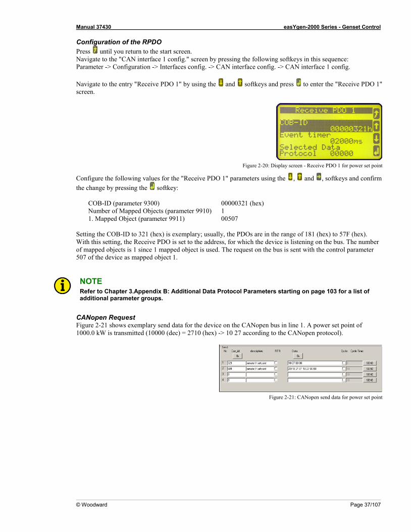
Manual 37430 easYgen-2000 Series - Genset Control
© Woodward Page 37/107
Configuration of the RPDO Press until you return to the start screen. Navigate to the "CAN interface 1 config." screen by pressing the following softkeys in this sequence: Parameter -> Configuration -> Interfaces config. -> CAN interface config. -> CAN interface 1 config. Navigate to the entry "Receive PDO 1" by using the and softkeys and press to enter the "Receive PDO 1" screen.
Figure 2-20: Display screen - Receive PDO 1 for power set point
Configure the following values for the "Receive PDO 1" parameters using the , and , softkeys and confirm the change by pressing the softkey:
COB-ID (parameter 9300) 00000321 (hex) Number of Mapped Objects (parameter 9910) 1 1. Mapped Object (parameter 9911) 00507
Setting the COB-ID to 321 (hex) is exemplary; usually, the PDOs are in the range of 181 (hex) to 57F (hex). With this setting, the Receive PDO is set to the address, for which the device is listening on the bus. The number of mapped objects is 1 since 1 mapped object is used. The request on the bus is sent with the control parameter 507 of the device as mapped object 1.
NOTE Refer to Chapter 3.Appendix B: Additional Data Protocol Parameters starting on page 103 for a list of additional parameter groups.
CANopen Request Figure 2-21 shows exemplary send data for the device on the CANopen bus in line 1. A power set point of 1000.0 kW is transmitted (10000 (dec) = 2710 (hex) -> 10 27 according to the CANopen protocol).
Figure 2-21: CANopen send data for power set point
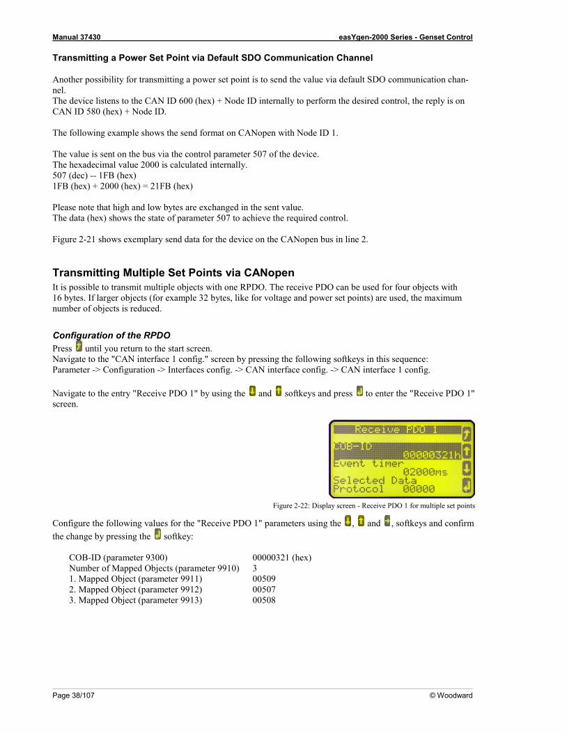
Manual 37430 easYgen-2000 Series - Genset Control
Page 38/107 © Woodward
Transmitting a Power Set Point via Default SDO Communication Channel
Another possibility for transmitting a power set point is to send the value via default SDO communication chan-nel. The device listens to the CAN ID 600 (hex) + Node ID internally to perform the desired control, the reply is on CAN ID 580 (hex) + Node ID. The following example shows the send format on CANopen with Node ID 1. The value is sent on the bus via the control parameter 507 of the device. The hexadecimal value 2000 is calculated internally. 507 (dec) -- 1FB (hex) 1FB (hex) + 2000 (hex) = 21FB (hex) Please note that high and low bytes are exchanged in the sent value. The data (hex) shows the state of parameter 507 to achieve the required control. Figure 2-21 shows exemplary send data for the device on the CANopen bus in line 2.
Transmitting Multiple Set Points via CANopen It is possible to transmit multiple objects with one RPDO. The receive PDO can be used for four objects with 16 bytes. If larger objects (for example 32 bytes, like for voltage and power set points) are used, the maximum number of objects is reduced.
Configuration of the RPDO Press until you return to the start screen. Navigate to the "CAN interface 1 config." screen by pressing the following softkeys in this sequence: Parameter -> Configuration -> Interfaces config. -> CAN interface config. -> CAN interface 1 config. Navigate to the entry "Receive PDO 1" by using the and softkeys and press to enter the "Receive PDO 1" screen.
Figure 2-22: Display screen - Receive PDO 1 for multiple set points
Configure the following values for the "Receive PDO 1" parameters using the , and , softkeys and confirm the change by pressing the softkey:
COB-ID (parameter 9300) 00000321 (hex) Number of Mapped Objects (parameter 9910) 3 1. Mapped Object (parameter 9911) 00509 2. Mapped Object (parameter 9912) 00507 3. Mapped Object (parameter 9913) 00508

Manual 37430 easYgen-2000 Series - Genset Control
© Woodward Page 39/107
Setting the COB-ID to 321 (hex) is exemplary; usually, the PDOs are in the range of 181 (hex) to 57F (hex). With this setting, the Receive PDO is set to the address, for which the device is listening on the bus. The number of mapped objects is 1 since 1 mapped object is used. The request on the bus is sent with the control parameters 509, 507, and 508 of the device as mapped object 1.
NOTE Refer to Chapter 3.Appendix B: Additional Data Protocol Parameters starting on page 103 for a list of additional parameter groups.
CANopen Request Figure 2-23 shows exemplary send data for the device on the CANopen bus in line 1. The following set points are transmitted: • Frequency 50.6 Hz (5060 (dec) = 13C4 (hex) -> C4 13 according to the CANopen protocol) • Power 1000 kW (10000 (dec) = 2710 (hex) -> 10 27 according to the CANopen protocol) • Power factor 0.9 lagging (900 (dec) = 0384 (hex) -> 84 03 according to the CANopen protocol)
Figure 2-23: CANopen send data for multiple set points
Remotely Changing the Set Point via CANopen It is possible to remotely change a set point value via the CANopen interface using the parameter ID 504 (refer to Remote Control Word 2 - Object 21F8h (Parameter ID 504) on page 104). In order to use the LogicsManager command variables for example to enable the second set, different bits of parameter ID 504 must be enabled: • [04.37] Remote voltage set point 2 bit 4 10 00 (hex) must be sent to parameter ID 504 • [04.38] Remote frequency set point 2 bit 5 20 00 (hex) must be sent to parameter ID 504 • [04.39] Remote Power Factor set point 2 bit 6 30 00 (hex) must be sent to parameter ID 504 • [04.40] Remote power set point 2 bit 7 80 00 (hex) must be sent to parameter ID 504
NOTE For remotely changing the control set points, it is necessary to use the interface set points instead of the internal set points as data source in the respective controller. For example, use data source "[05.03] Interface freq.setp." in parameter 5518 (Freq. setpoint 1 source) to transmit a frequency set point via interface.
Two different methods for changing a set point via CANopen interface are detailed in the following. Refer to Comparison of the Two Methods on page 26 for the basic differences of these methods.
Changing a Set Point via RPDO
Configuration of CAN Interface 1 Be sure to enable CAN-Open Master (parameter 8993) if there is no PLC taking over the master function. Refer to Configuration of CAN Interface 1 on page 26 for the configuration of this parameter.

Manual 37430 easYgen-2000 Series - Genset Control
Page 40/107 © Woodward
Configuration of the RPDO Press until you return to the start screen. Navigate to the "CAN interface 1 config." screen by pressing the following softkeys in this sequence: Parameter -> Configuration -> Interfaces config. -> CAN interface config. -> CAN interface 1 config. Navigate to the entry "Receive PDO 1" by using the and softkeys and press to enter the "Receive PDO 1" screen.
Figure 2-24: Display screen - Receive PDO 1 for changing the set point
Configure the following values for the "Receive PDO 1" parameters using the , and , softkeys and confirm the change by pressing the softkey:
COB-ID (parameter 9300) 00000321 (hex) Number of Mapped Objects (parameter 9910) 1 1. Mapped Object (parameter 9911) 00504
Setting the COB-ID to 321 (hex) is exemplary; usually, the PDOs are in the range of 181 (hex) to 57F (hex). With this setting, the Receive PDO is set to the address, for which the device is listening on the bus. The number of mapped objects is 1 since 1 mapped object is used. The request on the bus is sent with the control parameter 504 of the device as mapped object 1.
CANopen Request Figure 2-25 shows exemplary send data for the device on the CANopen bus. The respective bits are enabled by sending the data of the respective lines.
Figure 2-25: CANopen send data for changing the set point

Manual 37430 easYgen-2000 Series - Genset Control
© Woodward Page 41/107
Changing a Set Point via Default SDO Communication Channel
Another possibility for changing a set point is to enable the bit via default SDO communication channel. The device listens to the CAN ID 600 (hex) + Node ID internally to perform the desired control, the reply is on CAN ID 580 (hex) + Node ID. The following example shows the send format on CANopen with Node ID 1. The value is sent on the bus via the control parameter 504 of the device. The hexadecimal value 2000 is calculated internally. 509 (dec) -- 1F8 (hex) 1F8 (hex) + 2000 (hex) = 21F8 (hex) Please note that high and low bytes are exchanged in the sent value. The data (hex) shows the state of parameter 504 to achieve the required control. Figure 2-26 shows exemplary send data for the device on the CANopen bus.
Figure 2-26: CANopen send data for Node ID 1 for changing the set point
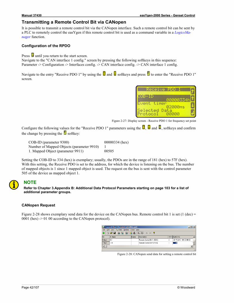
Manual 37430 easYgen-2000 Series - Genset Control
Page 42/107 © Woodward
Transmitting a Remote Control Bit via CANopen It is possible to transmit a remote control bit via the CANopen interface. Such a remote control bit can be sent by a PLC to remotely control the easYgen if this remote control bit is used as a command variable in a LogicsMa-nager function.
Configuration of the RPDO
Press until you return to the start screen. Navigate to the "CAN interface 1 config." screen by pressing the following softkeys in this sequence: Parameter -> Configuration -> Interfaces config. -> CAN interface config. -> CAN interface 1 config. Navigate to the entry "Receive PDO 1" by using the and softkeys and press to enter the "Receive PDO 1" screen.
Figure 2-27: Display screen - Receive PDO 1 for frequency set point
Configure the following values for the "Receive PDO 1" parameters using the , and , softkeys and confirm the change by pressing the softkey:
COB-ID (parameter 9300) 00000334 (hex) Number of Mapped Objects (parameter 9910) 1 1. Mapped Object (parameter 9911) 00505
Setting the COB-ID to 334 (hex) is exemplary; usually, the PDOs are in the range of 181 (hex) to 57F (hex). With this setting, the Receive PDO is set to the address, for which the device is listening on the bus. The number of mapped objects is 1 since 1 mapped object is used. The request on the bus is sent with the control parameter 505 of the device as mapped object 1.
NOTE Refer to Chapter 3.Appendix B: Additional Data Protocol Parameters starting on page 103 for a list of additional parameter groups.
CANopen Request
Figure 2-28 shows exemplary send data for the device on the CANopen bus. Remote control bit 1 is set (1 (dec) = 0001 (hex) -> 01 00 according to the CANopen protocol).
Figure 2-28: CANopen send data for setting a remote control bit
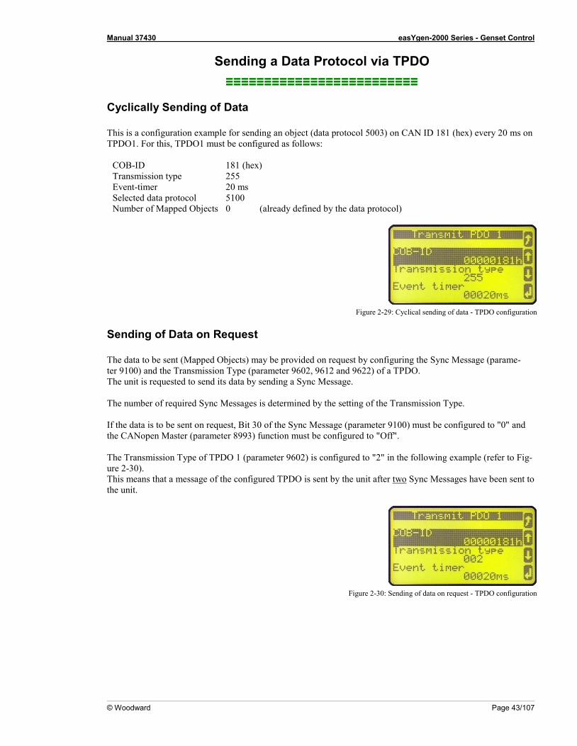
Manual 37430 easYgen-2000 Series - Genset Control
© Woodward Page 43/107
Sending a Data Protocol via TPDO ≡≡≡≡≡≡≡≡≡≡≡≡≡≡≡≡≡≡≡≡≡≡≡≡≡
Cyclically Sending of Data This is a configuration example for sending an object (data protocol 5003) on CAN ID 181 (hex) every 20 ms on TPDO1. For this, TPDO1 must be configured as follows:
COB-ID 181 (hex) Transmission type 255 Event-timer 20 ms Selected data protocol 5100 Number of Mapped Objects 0 (already defined by the data protocol)
Figure 2-29: Cyclical sending of data - TPDO configuration
Sending of Data on Request The data to be sent (Mapped Objects) may be provided on request by configuring the Sync Message (parame-ter 9100) and the Transmission Type (parameter 9602, 9612 and 9622) of a TPDO. The unit is requested to send its data by sending a Sync Message. The number of required Sync Messages is determined by the setting of the Transmission Type. If the data is to be sent on request, Bit 30 of the Sync Message (parameter 9100) must be configured to "0" and the CANopen Master (parameter 8993) function must be configured to "Off". The Transmission Type of TPDO 1 (parameter 9602) is configured to "2" in the following example (refer to Fig-ure 2-30). This means that a message of the configured TPDO is sent by the unit after two Sync Messages have been sent to the unit.
Figure 2-30: Sending of data on request - TPDO configuration
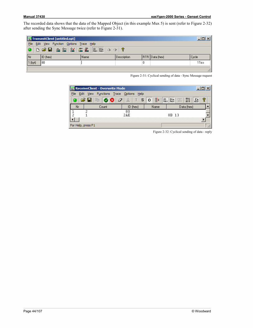
Manual 37430 easYgen-2000 Series - Genset Control
Page 44/107 © Woodward
The recorded data shows that the data of the Mapped Object (in this example Mux 5) is sent (refer to Figure 2-32) after sending the Sync Message twice (refer to Figure 2-31).
Figure 2-31: Cyclical sending of data - Sync Message request
Figure 2-32: Cyclical sending of data - reply

Manual 37430 easYgen-2000 Series - Genset Control
© Woodward Page 45/107
External IOs on CAN Interface 1 ≡≡≡≡≡≡≡≡≡≡≡≡≡≡≡≡≡≡≡≡≡≡≡≡≡
Usually, external expansion boards, like a Woodward IKD 1 or Phoenix expansion boards are configured on CAN interface 2. However, it is possible to configure them on CAN interface 1 as well. The following examples describe how to configure an IKD 1 on CAN interface 1.
External DOs for an IKD 1 This is a configuration example for sending objects with the data protocol 65000 on CAN ID 181h every 20 ms on TPDO1. This is used to send messages to an external device. For this, TPDO1 must be configured as follows:
COB-ID 181 (hex) Transmission type 255 Event-timer 20 ms Selected data protocol 65000 Number of Mapped Objects 0 (already defined by the data protocol)
NOTE This is an example of how to configure an IKD 1 on CAN interface 1. Usually, IKDs may be configured to CAN interface 2 much easier.
Receiving Data from an IKD 1 This is a configuration example for an RPDO configuration. The data received on CAN ID 201h is interpreted as object with the data protocol 65000 (external DIs 1 to 8). For this, RPDO must be configured as follows:
COB-ID 201 (hex) Selected data protocol 65000 Number of Mapped Objects 0 (already defined by the data protocol)
NOTE This is an example of how to configure an IKD 1 on CAN interface 1. Usually, IKDs may be configured to CAN interface 2 much easier.
Manual 37430 easYgen-2000 Series - Genset Control
Page 46/107 © Woodward
Troubleshooting ≡≡≡≡≡≡≡≡≡≡≡≡≡≡≡≡≡≡≡≡≡≡≡≡≡
General Connected device (Phoenix IO board) cannot be configured
o Are all LEDs at the expansion modules illuminated green (i.e. correctly connected)? o Are all modules detected (i.e. no blinking expansion module)?
Guidance Level CAN Bus #1 No Data is sent by the easYgen
o Is the unit in operational mode (heartbeat - CAN ID 700 (hex) + Node-ID has the content 5 (hex)? o Are the TPDOs correctly configured (CAN ID, mapping, parameter)?
No Data is received by the easYgen
o Is the unit in operational mode (heartbeat - CAN ID 700 (hex) + Node-ID has the content 5 (hex)? o Are the RPDOs correctly configured (CAN ID, mapping, parameter)?
No monitoring bit data is received on the RPDO
o Is the CAN bus connected correctly? o Is the baud rate configured correctly? o Is the CAN ID assigned more than once? o Is the unit in operational mode? If not, start it via an other device or put in NMT Master (parameter 8993).
No SDOs (configuration messages) are received by the unit
o Is the CAN ID assigned more than once? o Is the CAN ID 600 (hex) + Node-ID of the easYgen already used in a PDO (COB ID)? o Are RPDOs or TPDOs higher then 580 (hex) or lower than 180 (hex) used?

Manual 37430 easYgen-2000 Series - Genset Control
© Woodward Page 47/107
Chapter 3. Modbus Communications
General Information ≡≡≡≡≡≡≡≡≡≡≡≡≡≡≡≡≡≡≡≡≡≡≡≡≡
Modbus is a serial communications protocol published by Modicon in 1979 for use with its programmable logic controllers (PLCs). It has become a de facto standard communications protocol in industry, and is now the most commonly available means of connecting industrial electronic devices. The easYgen-2000 Series supports a Modbus RTU Slave module. This means that a Master node needs to poll the easYgen slave node. Modbus RTU can also be multi-dropped, or in other words, multiple Slave devices can exist on one Modbus RTU network, as-suming that the serial interface is a RS-485. Detailed Information about the Modbus protocol are available on the following website: http://www.modbus.org/specs.php There are also various tools available on the internet. We recommend to use ModScan32 which is a Windows ap-plication designed to operate as a Modbus Master device for accessing data points in a connected Modbus Slave device. It is designed primarily as a testing device for verification of correct protocol operation in new or existing systems. It is possible to download a trial version from the following website: http://www.win-tech.com/html/modscan32.htm

Manual 37430 easYgen-2000 Series - Genset Control
Page 48/107 © Woodward
Address Range ≡≡≡≡≡≡≡≡≡≡≡≡≡≡≡≡≡≡≡≡≡≡≡≡≡
The easYgen Modbus Slave module distinguishes between visualization data and configuration & remote control data. The different data is accessible over a split address range and can be read via the "Read Holding Register" function. Furthermore, easYgen parameters and remote control data can be written with the "Preset Single Regis-ters" function or "Preset Multiple Registers" (refer to Table 3-1).
Modbus address:
easYgen
visualization data
Modbus function codes:
Read Holding Register (0x03) 450001 450000
easYgen
remote control &
configuration data
Read Holding Register (0x03) Preset Multiple Registers (0x10) Preset Single Register (0x06) 40001
Table 3-1: Modbus - address range
NOTE All addresses in this document comply with the Modicon address convention. Some PLCs or PC pro-grams use different address conventions depending on their implementation. Then the address must be increased and the leading 4 may be omitted. Please refer to your PLC or program manual for more information. This determines the address sent over the bus in the Modbus telegram. The Modbus starting address 450001 of the visualization data may become bus address 50000 for example.
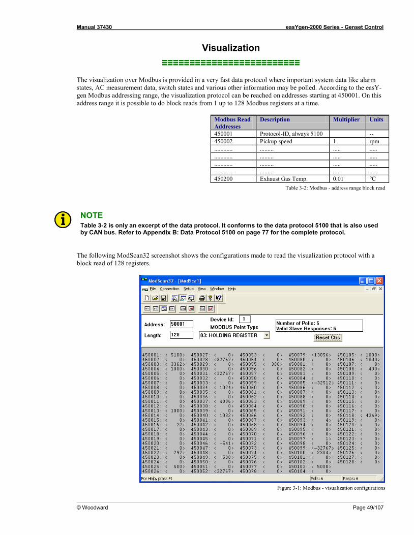
Manual 37430 easYgen-2000 Series - Genset Control
© Woodward Page 49/107
Visualization ≡≡≡≡≡≡≡≡≡≡≡≡≡≡≡≡≡≡≡≡≡≡≡≡≡
The visualization over Modbus is provided in a very fast data protocol where important system data like alarm states, AC measurement data, switch states and various other information may be polled. According to the easY-gen Modbus addressing range, the visualization protocol can be reached on addresses starting at 450001. On this address range it is possible to do block reads from 1 up to 128 Modbus registers at a time.
Modbus Read Addresses
Description Multiplier Units
450001 Protocol-ID, always 5100 -- 450002 Pickup speed 1 rpm ............ ......... ..... ..... ............ ......... ..... ..... ............ ......... ..... ..... ............ ......... ..... ..... 450200 Exhaust Gas Temp. 0.01 °C
Table 3-2: Modbus - address range block read
NOTE Table 3-2 is only an excerpt of the data protocol. It conforms to the data protocol 5100 that is also used by CAN bus. Refer to Appendix B: Data Protocol 5100 on page 77 for the complete protocol.
The following ModScan32 screenshot shows the configurations made to read the visualization protocol with a block read of 128 registers.
Figure 3-1: Modbus - visualization configurations
Manual 37430 easYgen-2000 Series - Genset Control
Page 50/107 © Woodward
Configuration ≡≡≡≡≡≡≡≡≡≡≡≡≡≡≡≡≡≡≡≡≡≡≡≡≡
The Modbus interface can be used to read/write parameters of the easYgen. According to the easYgen Modbus addressing range for the configuration addresses, the range starts at 40001 and ends at 450000. You can always access only one parameter of the system in this address range. The Modbus address can be calculated depending on the parameter ID as illustrated below:
Parameter ID < 10000 Parameter ID >= 10000 Modbus address = 40000 + (Par. ID+1) 400000 + (Par. ID+1)
Table 3-3: Modbus - address calculation
Block reads in this address range depend on the data type of the parameter. This makes it important to set the cor-rect length in Modbus registers which depends on the data type (UNSIGNED 8, INTEGER 16, etc.). Refer to Ta-ble 3-4 for more information.
easYgen types
Modbus registers
UNSIGNED 8 1 UNSIGNED 16 1 INTEGER 16 1
UNSIGNED 32 2 INTEGER 32 2
LOGMAN 7 TEXT/X X/2
Table 3-4: Modbus - data types

Manual 37430 easYgen-2000 Series - Genset Control
© Woodward Page 51/107
Remote Control via Modbus ≡≡≡≡≡≡≡≡≡≡≡≡≡≡≡≡≡≡≡≡≡≡≡≡≡
Remote Start, Stop, and Acknowledgement via Modbus The easYgen controller may be configured to perform start/stop/acknowledgement functions remotely through the Modbus. The required procedure is detailed in the following steps.
NOTE The following descriptions refer to the remote control parameter 503 as described under Remote Con-trol Word 1 - Object 21F7h (Parameter ID 503) on page 103. It may be necessary to shift the address by 1 depending on the used PC software. In this case, the ad-dress would be 504 for example. Be sure to check both possibilities in case of remote control problems.
Par. ID. Parameter Setting range Data type
503 Remote control word 1 0 to 65535 UNSIGNED 16 Modbus address = 40000 + (Par. ID +1) = 40504 Modbus length = 1 (UNSIGNED 16) In order to issue a command, the respective bit of object 21F7 (hex), i.e. parameter ID 503, must be enabled. The following bits are used for this: Bit 0 Start bit – this bit activates the LogicsManager command variable [04.13] "Remote request" and enables a
remote request command Bit 1 Stop bit – this bit deactivates the LogicsManager command variable [04.13] "Remote request" and dis-
ables a remote request command Bit 4 Acknowledgement bit – this bit activates the LogicsManager command variable [04.14] "Remote ac-
knowledge". This bit must be set and reset twice to acknowledge an alarm completely. The first rising edge disables the horn and the second rising edge resets the alarm.
The following Modscan32 screenshot shows the configurations made to remote control parameter ID 503. It is possible to set the format to binary to view single bits using the "display options".
Figure 3-2: Modbus - remote control parameter 503
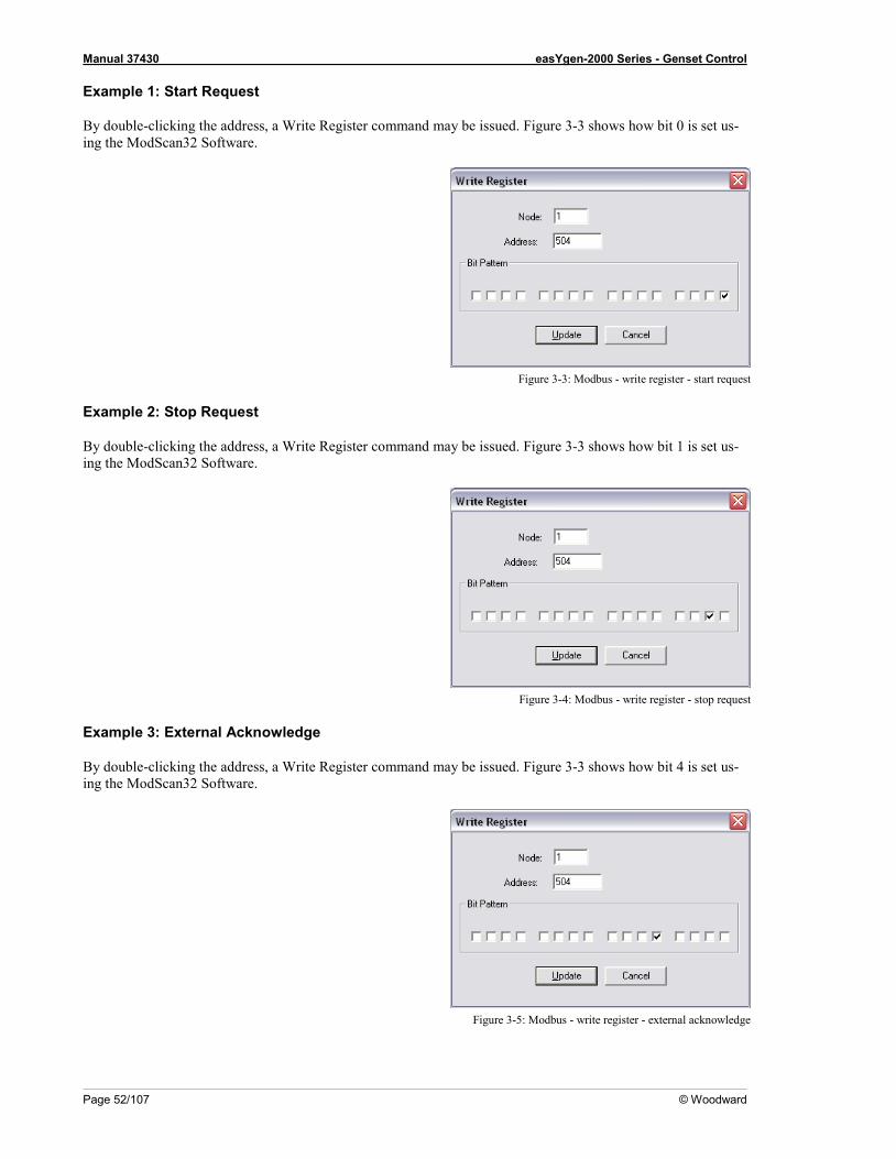
Manual 37430 easYgen-2000 Series - Genset Control
Page 52/107 © Woodward
Example 1: Start Request
By double-clicking the address, a Write Register command may be issued. Figure 3-3 shows how bit 0 is set us-ing the ModScan32 Software.
Figure 3-3: Modbus - write register - start request
Example 2: Stop Request
By double-clicking the address, a Write Register command may be issued. Figure 3-3 shows how bit 1 is set us-ing the ModScan32 Software.
Figure 3-4: Modbus - write register - stop request
Example 3: External Acknowledge
By double-clicking the address, a Write Register command may be issued. Figure 3-3 shows how bit 4 is set us-ing the ModScan32 Software.
Figure 3-5: Modbus - write register - external acknowledge
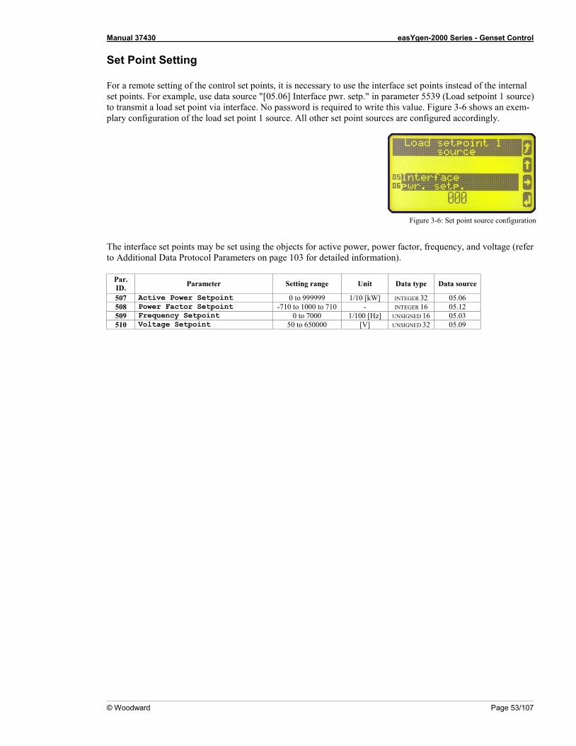
Manual 37430 easYgen-2000 Series - Genset Control
© Woodward Page 53/107
Set Point Setting For a remote setting of the control set points, it is necessary to use the interface set points instead of the internal set points. For example, use data source "[05.06] Interface pwr. setp." in parameter 5539 (Load setpoint 1 source) to transmit a load set point via interface. No password is required to write this value. Figure 3-6 shows an exem-plary configuration of the load set point 1 source. All other set point sources are configured accordingly.
Figure 3-6: Set point source configuration
The interface set points may be set using the objects for active power, power factor, frequency, and voltage (refer to Additional Data Protocol Parameters on page 103 for detailed information).
Par. ID. Parameter Setting range Unit Data type Data source
507 Active Power Setpoint 0 to 999999 1/10 [kW] INTEGER 32 05.06 508 Power Factor Setpoint -710 to 1000 to 710 - INTEGER 16 05.12 509 Frequency Setpoint 0 to 7000 1/100 [Hz] UNSIGNED 16 05.03 510 Voltage Setpoint 50 to 650000 [V] UNSIGNED 32 05.09

Manual 37430 easYgen-2000 Series - Genset Control
Page 54/107 © Woodward
Example 1: Active Power Interface Set Point
The active power set point value must be written to object 21FB (hex), i.e. parameter ID 507 Example: A power value of 50 kw = 500 (dec) =01F4 (hex) is to be transmitted. Modbus address = 40000 + (Par. ID + 1) = 40508 Modbus length = 2 (INTEGER 32) The high word is to be written to the lower address and the low word is to be written to the higher address. Figure 3-7 through Figure 3-10 show how to set the parameter address 507 in ModScan32.
Figure 3-7: Modbus - configuration example 4 - active power
Open the Preset Multiple registers window by selecting Setup -> Extended -> Preset Regs from the menu.
Figure 3-8: Modbus - configuration example 4 - active power
Select OK and enter the desired values.
Figure 3-9: Modbus - configuration example 4 - active power
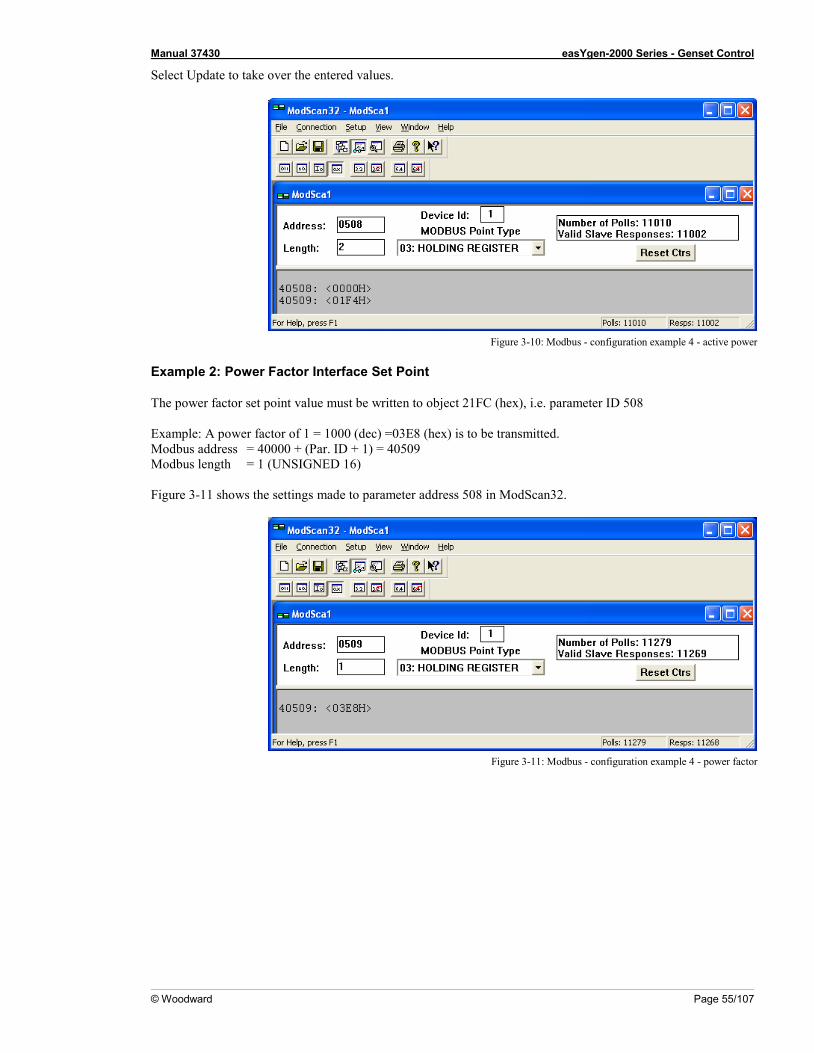
Manual 37430 easYgen-2000 Series - Genset Control
© Woodward Page 55/107
Select Update to take over the entered values.
Figure 3-10: Modbus - configuration example 4 - active power
Example 2: Power Factor Interface Set Point
The power factor set point value must be written to object 21FC (hex), i.e. parameter ID 508 Example: A power factor of 1 = 1000 (dec) =03E8 (hex) is to be transmitted. Modbus address = 40000 + (Par. ID + 1) = 40509 Modbus length = 1 (UNSIGNED 16) Figure 3-11 shows the settings made to parameter address 508 in ModScan32.
Figure 3-11: Modbus - configuration example 4 - power factor
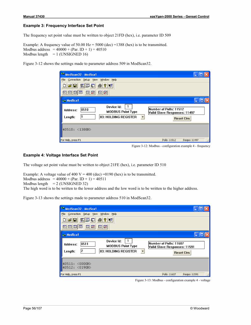
Manual 37430 easYgen-2000 Series - Genset Control
Page 56/107 © Woodward
Example 3: Frequency Interface Set Point
The frequency set point value must be written to object 21FD (hex), i.e. parameter ID 509 Example: A frequency value of 50.00 Hz = 5000 (dec) =1388 (hex) is to be transmitted. Modbus address = 40000 + (Par. ID + 1) = 40510 Modbus length = 1 (UNSIGNED 16) Figure 3-12 shows the settings made to parameter address 509 in ModScan32.
Figure 3-12: Modbus - configuration example 4 - frequency
Example 4: Voltage Interface Set Point
The voltage set point value must be written to object 21FE (hex), i.e. parameter ID 510 Example: A voltage value of 400 V = 400 (dec) =0190 (hex) is to be transmitted. Modbus address = 40000 + (Par. ID + 1) = 40511 Modbus length = 2 (UNSIGNED 32) The high word is to be written to the lower address and the low word is to be written to the higher address. Figure 3-13 shows the settings made to parameter address 510 in ModScan32.
Figure 3-13: Modbus - configuration example 4 - voltage
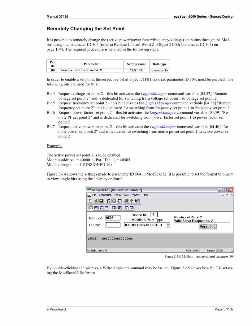
Manual 37430 easYgen-2000 Series - Genset Control
© Woodward Page 57/107
Remotely Changing the Set Point It is possible to remotely change the (active power/power factor/frequency/voltage) set points through the Mod-bus using the parameter ID 504 (refer to Remote Control Word 2 - Object 21F8h (Parameter ID 504) on page 104). The required procedure is detailed in the following steps.
Par. ID. Parameter Setting range Data type
504 Remote control word 2 YES / NO UNSIGNED 16 In order to enable a set point, the respective bit of object 21F8 (hex), i.e. parameter ID 504, must be enabled. The following bits are used for this: Bit 4 Request voltage set point 2 – this bit activates the LogicsManager command variable [04.37] "Remote
voltage set point 2" and is dedicated for switching from voltage set point 1 to voltage set point 2 Bit 5 Request frequency set point 2 – this bit activates the LogicsManager command variable [04.38] "Remote
frequency set point 2" and is dedicated for switching from frequency set point 1 to frequency set point 2 Bit 6 Request power factor set point 2 – this bit activates the LogicsManager command variable [04.39] "Re-
mote PF set point 2" and is dedicated for switching from power factor set point 1 to power factor set point 2
Bit 7 Request active power set point 2 – this bit activates the LogicsManager command variable [04.40] "Re-mote power set point 2" and is dedicated for switching from active power set point 1 to active power set point 2
Example: The active power set point 2 is to be enabled. Modbus address = 40000 + (Par. ID + 1) = 40505 Modbus length = 1 (UNSIGNED 16) Figure 3-14 shows the settings made to parameter ID 504 in ModScan32. It is possible to set the format to binary to view single bits using the "display options".
Figure 3-14: Modbus - remote control parameter 504
By double-clicking the address, a Write Register command may be issued. Figure 3-15 shows how bit 7 is set us-ing the ModScan32 Software.

Manual 37430 easYgen-2000 Series - Genset Control
Page 58/107 © Woodward
Figure 3-15: Modbus - write register - enable active power set point 2
Figure 3-16 shows how bit 6 would be set to enable the power factor set point 2.
Figure 3-16: Modbus - write register - enable power factor set point 2
Figure 3-17 shows how bit 5 would be set to enable the frequency set point 2.
Figure 3-17: Modbus - write register - enable frequency set point 2
Figure 3-17 shows how bit 4 would be set to enable the voltage set point 2.
Figure 3-18: Modbus - write register - enable voltage set point 2
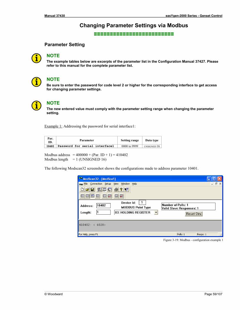
Manual 37430 easYgen-2000 Series - Genset Control
© Woodward Page 59/107
Changing Parameter Settings via Modbus ≡≡≡≡≡≡≡≡≡≡≡≡≡≡≡≡≡≡≡≡≡≡≡≡≡
Parameter Setting
NOTE The example tables below are excerpts of the parameter list in the Configuration Manual 37427. Please refer to this manual for the complete parameter list.
NOTE Be sure to enter the password for code level 2 or higher for the corresponding interface to get access for changing parameter settings.
NOTE The new entered value must comply with the parameter setting range when changing the parameter setting.
Example 1: Addressing the password for serial interface1:
Par. ID. Parameter Setting range Data type
10401 Password for serial interface1 0000 to 9999 UNSIGNED 16 Modbus address = 400000 + (Par. ID + 1) = 410402 Modbus length = 1 (UNSIGNED 16) The following Modscan32 screenshot shows the configurations made to address parameter 10401.
Figure 3-19: Modbus - configuration example 1
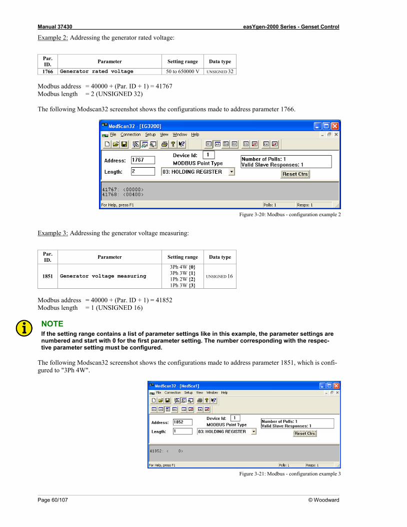
Manual 37430 easYgen-2000 Series - Genset Control
Page 60/107 © Woodward
Example 2: Addressing the generator rated voltage:
Par. ID. Parameter Setting range Data type
1766 Generator rated voltage 50 to 650000 V UNSIGNED 32 Modbus address = 40000 + (Par. ID + 1) = 41767 Modbus length = 2 (UNSIGNED 32) The following Modscan32 screenshot shows the configurations made to address parameter 1766.
Figure 3-20: Modbus - configuration example 2
Example 3: Addressing the generator voltage measuring:
Par. ID. Parameter Setting range Data type
1851 Generator voltage measuring
3Ph 4W {0} 3Ph 3W {1} 1Ph 2W {2} 1Ph 3W {3}
UNSIGNED 16
Modbus address = 40000 + (Par. ID + 1) = 41852 Modbus length = 1 (UNSIGNED 16)
NOTE If the setting range contains a list of parameter settings like in this example, the parameter settings are numbered and start with 0 for the first parameter setting. The number corresponding with the respec-tive parameter setting must be configured.
The following Modscan32 screenshot shows the configurations made to address parameter 1851, which is confi-gured to "3Ph 4W".
Figure 3-21: Modbus - configuration example 3
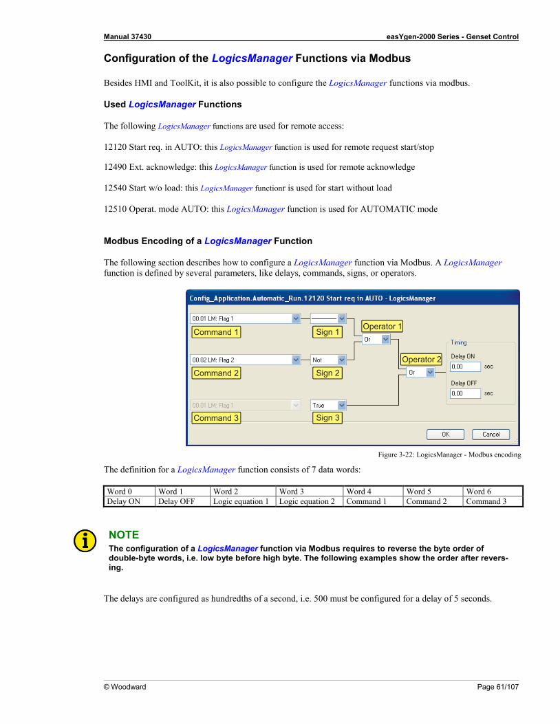
Manual 37430 easYgen-2000 Series - Genset Control
© Woodward Page 61/107
Configuration of the LogicsManager Functions via Modbus Besides HMI and ToolKit, it is also possible to configure the LogicsManager functions via modbus.
Used LogicsManager Functions
The following LogicsManager functions are used for remote access: 12120 Start req. in AUTO: this LogicsManager function is used for remote request start/stop 12490 Ext. acknowledge: this LogicsManager function is used for remote acknowledge 12540 Start w/o load: this LogicsManager functionr is used for start without load 12510 Operat. mode AUTO: this LogicsManager function is used for AUTOMATIC mode
Modbus Encoding of a LogicsManager Function
The following section describes how to configure a LogicsManager function via Modbus. A LogicsManager function is defined by several parameters, like delays, commands, signs, or operators.
Figure 3-22: LogicsManager - Modbus encoding
The definition for a LogicsManager function consists of 7 data words: Word 0 Word 1 Word 2 Word 3 Word 4 Word 5 Word 6 Delay ON Delay OFF Logic equation 1 Logic equation 2 Command 1 Command 2 Command 3
NOTE The configuration of a LogicsManager function via Modbus requires to reverse the byte order of double-byte words, i.e. low byte before high byte. The following examples show the order after revers-ing.
The delays are configured as hundredths of a second, i.e. 500 must be configured for a delay of 5 seconds.
Command 1
Command 2
Command 3
Sign 1
Sign 2
Sign 3
Sign 1Operator 1
Operator 2
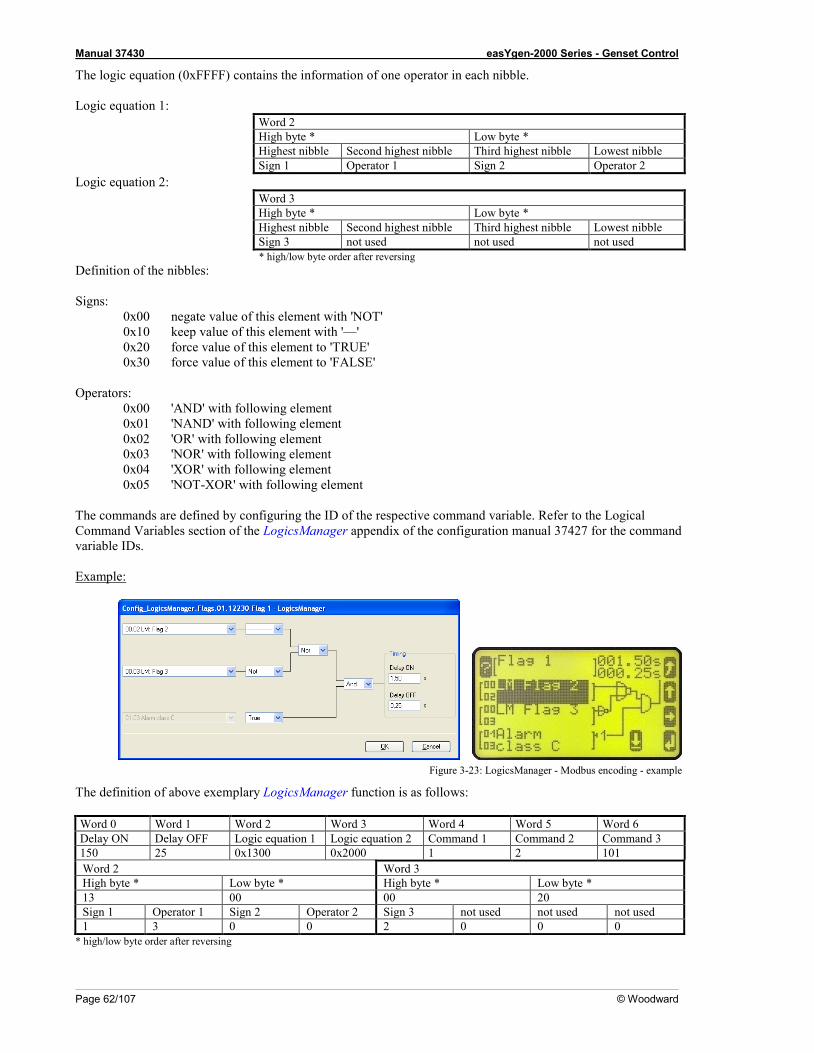
Manual 37430 easYgen-2000 Series - Genset Control
Page 62/107 © Woodward
The logic equation (0xFFFF) contains the information of one operator in each nibble. Logic equation 1:
Word 2 High byte * Low byte * Highest nibble Second highest nibble Third highest nibble Lowest nibble Sign 1 Operator 1 Sign 2 Operator 2
Logic equation 2: Word 3 High byte * Low byte * Highest nibble Second highest nibble Third highest nibble Lowest nibble Sign 3 not used not used not used * high/low byte order after reversing
Definition of the nibbles: Signs: 0x00 negate value of this element with 'NOT' 0x10 keep value of this element with '—' 0x20 force value of this element to 'TRUE' 0x30 force value of this element to 'FALSE' Operators: 0x00 'AND' with following element 0x01 'NAND' with following element 0x02 'OR' with following element 0x03 'NOR' with following element 0x04 'XOR' with following element 0x05 'NOT-XOR' with following element The commands are defined by configuring the ID of the respective command variable. Refer to the Logical Command Variables section of the LogicsManager appendix of the configuration manual 37427 for the command variable IDs. Example:
Figure 3-23: LogicsManager - Modbus encoding - example
The definition of above exemplary LogicsManager function is as follows: Word 0 Word 1 Word 2 Word 3 Word 4 Word 5 Word 6 Delay ON Delay OFF Logic equation 1 Logic equation 2 Command 1 Command 2 Command 3 150 25 0x1300 0x2000 1 2 101 Word 2 Word 3 High byte * Low byte * High byte * Low byte * 13 00 00 20 Sign 1 Operator 1 Sign 2 Operator 2 Sign 3 not used not used not used 1 3 0 0 2 0 0 0
* high/low byte order after reversing
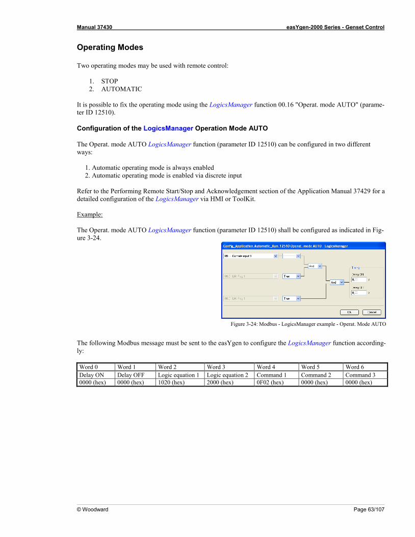
Manual 37430 easYgen-2000 Series - Genset Control
© Woodward Page 63/107
Operating Modes Two operating modes may be used with remote control:
1. STOP 2. AUTOMATIC
It is possible to fix the operating mode using the LogicsManager function 00.16 "Operat. mode AUTO" (parame-ter ID 12510).
Configuration of the LogicsManager Operation Mode AUTO
The Operat. mode AUTO LogicsManager function (parameter ID 12510) can be configured in two different ways:
1. Automatic operating mode is always enabled 2. Automatic operating mode is enabled via discrete input
Refer to the Performing Remote Start/Stop and Acknowledgement section of the Application Manual 37429 for a detailed configuration of the LogicsManager via HMI or ToolKit. Example: The Operat. mode AUTO LogicsManager function (parameter ID 12510) shall be configured as indicated in Fig-ure 3-24.
Figure 3-24: Modbus - LogicsManager example - Operat. Mode AUTO
The following Modbus message must be sent to the easYgen to configure the LogicsManager function according-ly: Word 0 Word 1 Word 2 Word 3 Word 4 Word 5 Word 6 Delay ON Delay OFF Logic equation 1 Logic equation 2 Command 1 Command 2 Command 3 0000 (hex) 0000 (hex) 1020 (hex) 2000 (hex) 0F02 (hex) 0000 (hex) 0000 (hex)
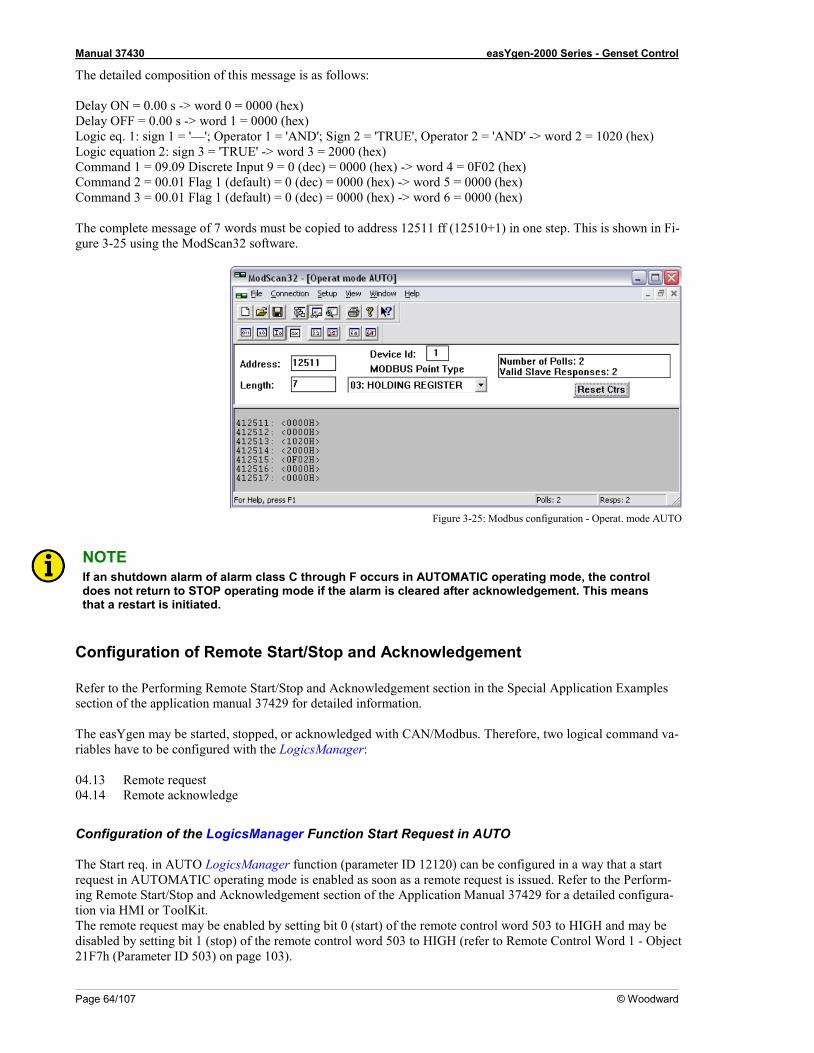
Manual 37430 easYgen-2000 Series - Genset Control
Page 64/107 © Woodward
The detailed composition of this message is as follows: Delay ON = 0.00 s -> word 0 = 0000 (hex) Delay OFF = 0.00 s -> word 1 = 0000 (hex) Logic eq. 1: sign 1 = '—'; Operator 1 = 'AND'; Sign 2 = 'TRUE', Operator 2 = 'AND' -> word 2 = 1020 (hex) Logic equation 2: sign 3 = 'TRUE' -> word 3 = 2000 (hex) Command 1 = 09.09 Discrete Input 9 = 0 (dec) = 0000 (hex) -> word 4 = 0F02 (hex) Command 2 = 00.01 Flag 1 (default) = 0 (dec) = 0000 (hex) -> word 5 = 0000 (hex) Command 3 = 00.01 Flag 1 (default) = 0 (dec) = 0000 (hex) -> word 6 = 0000 (hex) The complete message of 7 words must be copied to address 12511 ff (12510+1) in one step. This is shown in Fi-gure 3-25 using the ModScan32 software.
Figure 3-25: Modbus configuration - Operat. mode AUTO
NOTE If an shutdown alarm of alarm class C through F occurs in AUTOMATIC operating mode, the control does not return to STOP operating mode if the alarm is cleared after acknowledgement. This means that a restart is initiated.
Configuration of Remote Start/Stop and Acknowledgement Refer to the Performing Remote Start/Stop and Acknowledgement section in the Special Application Examples section of the application manual 37429 for detailed information. The easYgen may be started, stopped, or acknowledged with CAN/Modbus. Therefore, two logical command va-riables have to be configured with the LogicsManager: 04.13 Remote request 04.14 Remote acknowledge
Configuration of the LogicsManager Function Start Request in AUTO The Start req. in AUTO LogicsManager function (parameter ID 12120) can be configured in a way that a start request in AUTOMATIC operating mode is enabled as soon as a remote request is issued. Refer to the Perform-ing Remote Start/Stop and Acknowledgement section of the Application Manual 37429 for a detailed configura-tion via HMI or ToolKit. The remote request may be enabled by setting bit 0 (start) of the remote control word 503 to HIGH and may be disabled by setting bit 1 (stop) of the remote control word 503 to HIGH (refer to Remote Control Word 1 - Object 21F7h (Parameter ID 503) on page 103).
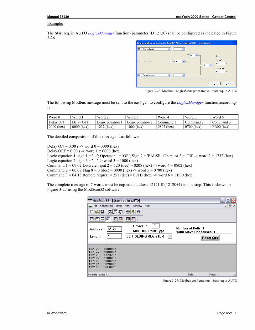
Manual 37430 easYgen-2000 Series - Genset Control
© Woodward Page 65/107
Example: The Start req. in AUTO LogicsManager function (parameter ID 12120) shall be configured as indicated in Figure 3-26.
Figure 3-26: Modbus - LogicsManager example - Start req. in AUTO
The following Modbus message must be sent to the easYgen to configure the LogicsManager function according-ly: Word 0 Word 1 Word 2 Word 3 Word 4 Word 5 Word 6 Delay ON Delay OFF Logic equation 1 Logic equation 2 Command 1 Command 2 Command 3 0000 (hex) 0000 (hex) 1232 (hex) 1000 (hex) 0802 (hex) 0700 (hex) FB00 (hex)
The detailed composition of this message is as follows: Delay ON = 0.00 s -> word 0 = 0000 (hex) Delay OFF = 0.00 s -> word 1 = 0000 (hex) Logic equation 1: sign 1 = '—'; Operator 1 = 'OR'; Sign 2 = 'FALSE', Operator 2 = 'OR' -> word 2 = 1232 (hex) Logic equation 2: sign 3 = '—' -> word 3 = 1000 (hex) Command 1 = 09.02 Discrete input 2 = 520 (dec) = 0208 (hex) -> word 4 = 0802 (hex) Command 2 = 00.08 Flag 8 = 0 (dec) = 0000 (hex) -> word 5 = 0700 (hex) Command 3 = 04.13 Remote request = 251 (dec) = 00FB (hex) -> word 6 = FB00 (hex) The complete message of 7 words must be copied to address 12121 ff (12120+1) in one step. This is shown in Figure 3-27 using the ModScan32 software.
Figure 3-27: Modbus configuration - Start req in AUTO
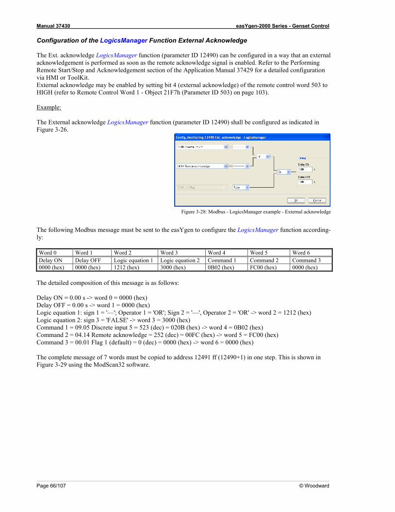
Manual 37430 easYgen-2000 Series - Genset Control
Page 66/107 © Woodward
Configuration of the LogicsManager Function External Acknowledge The Ext. acknowledge LogicsManager function (parameter ID 12490) can be configured in a way that an external acknowledgement is performed as soon as the remote acknowledge signal is enabled. Refer to the Performing Remote Start/Stop and Acknowledgement section of the Application Manual 37429 for a detailed configuration via HMI or ToolKit. External acknowledge may be enabled by setting bit 4 (external acknowledge) of the remote control word 503 to HIGH (refer to Remote Control Word 1 - Object 21F7h (Parameter ID 503) on page 103). Example: The External acknowledge LogicsManager function (parameter ID 12490) shall be configured as indicated in Figure 3-26.
Figure 3-28: Modbus - LogicsManager example - External acknowledge
The following Modbus message must be sent to the easYgen to configure the LogicsManager function according-ly: Word 0 Word 1 Word 2 Word 3 Word 4 Word 5 Word 6 Delay ON Delay OFF Logic equation 1 Logic equation 2 Command 1 Command 2 Command 3 0000 (hex) 0000 (hex) 1212 (hex) 3000 (hex) 0B02 (hex) FC00 (hex) 0000 (hex)
The detailed composition of this message is as follows: Delay ON = 0.00 s -> word 0 = 0000 (hex) Delay OFF = 0.00 s -> word 1 = 0000 (hex) Logic equation 1: sign 1 = '—'; Operator 1 = 'OR'; Sign 2 = '—', Operator 2 = 'OR' -> word 2 = 1212 (hex) Logic equation 2: sign 3 = 'FALSE' -> word 3 = 3000 (hex) Command 1 = 09.05 Discrete input 5 = 523 (dec) = 020B (hex) -> word 4 = 0B02 (hex) Command 2 = 04.14 Remote acknowledge = 252 (dec) = 00FC (hex) -> word 5 = FC00 (hex) Command 3 = 00.01 Flag 1 (default) = 0 (dec) = 0000 (hex) -> word 6 = 0000 (hex) The complete message of 7 words must be copied to address 12491 ff (12490+1) in one step. This is shown in Figure 3-29 using the ModScan32 software.
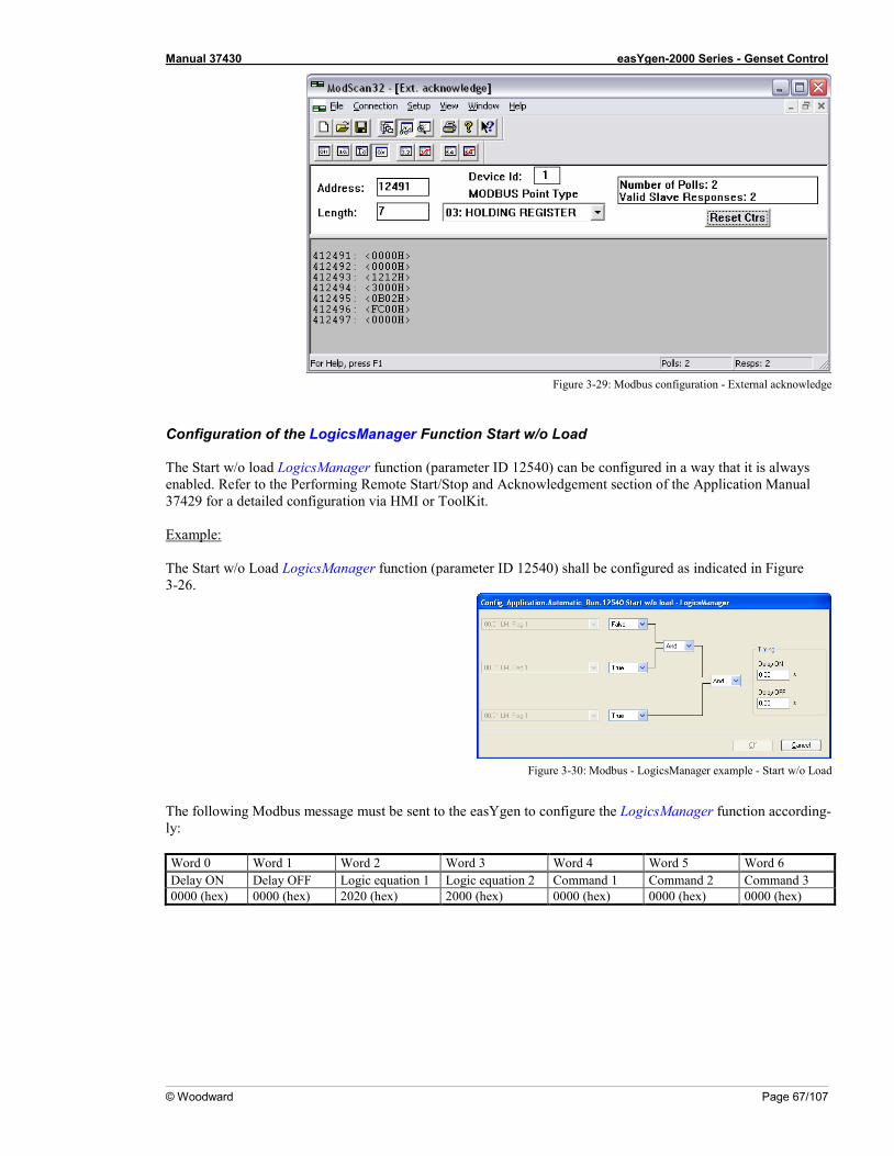
Manual 37430 easYgen-2000 Series - Genset Control
© Woodward Page 67/107
Figure 3-29: Modbus configuration - External acknowledge
Configuration of the LogicsManager Function Start w/o Load The Start w/o load LogicsManager function (parameter ID 12540) can be configured in a way that it is always enabled. Refer to the Performing Remote Start/Stop and Acknowledgement section of the Application Manual 37429 for a detailed configuration via HMI or ToolKit. Example: The Start w/o Load LogicsManager function (parameter ID 12540) shall be configured as indicated in Figure 3-26.
Figure 3-30: Modbus - LogicsManager example - Start w/o Load
The following Modbus message must be sent to the easYgen to configure the LogicsManager function according-ly: Word 0 Word 1 Word 2 Word 3 Word 4 Word 5 Word 6 Delay ON Delay OFF Logic equation 1 Logic equation 2 Command 1 Command 2 Command 3 0000 (hex) 0000 (hex) 2020 (hex) 2000 (hex) 0000 (hex) 0000 (hex) 0000 (hex)
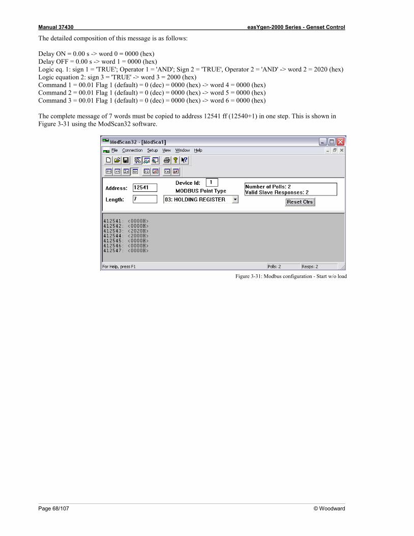
Manual 37430 easYgen-2000 Series - Genset Control
Page 68/107 © Woodward
The detailed composition of this message is as follows: Delay ON = 0.00 s -> word 0 = 0000 (hex) Delay OFF = 0.00 s -> word 1 = 0000 (hex) Logic eq. 1: sign 1 = 'TRUE'; Operator 1 = 'AND'; Sign 2 = 'TRUE', Operator 2 = 'AND' -> word 2 = 2020 (hex) Logic equation 2: sign 3 = 'TRUE' -> word 3 = 2000 (hex) Command 1 = 00.01 Flag 1 (default) = 0 (dec) = 0000 (hex) -> word 4 = 0000 (hex) Command 2 = 00.01 Flag 1 (default) = 0 (dec) = 0000 (hex) -> word 5 = 0000 (hex) Command 3 = 00.01 Flag 1 (default) = 0 (dec) = 0000 (hex) -> word 6 = 0000 (hex) The complete message of 7 words must be copied to address 12541 ff (12540+1) in one step. This is shown in Figure 3-31 using the ModScan32 software.
Figure 3-31: Modbus configuration - Start w/o load
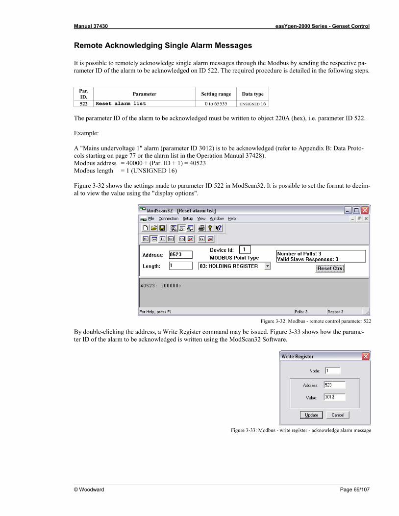
Manual 37430 easYgen-2000 Series - Genset Control
© Woodward Page 69/107
Remote Acknowledging Single Alarm Messages It is possible to remotely acknowledge single alarm messages through the Modbus by sending the respective pa-rameter ID of the alarm to be acknowledged on ID 522. The required procedure is detailed in the following steps.
Par. ID. Parameter Setting range Data type
522 Reset alarm list 0 to 65535 UNSIGNED 16 The parameter ID of the alarm to be acknowledged must be written to object 220A (hex), i.e. parameter ID 522. Example: A "Mains undervoltage 1" alarm (parameter ID 3012) is to be acknowledged (refer to Appendix B: Data Proto-cols starting on page 77 or the alarm list in the Operation Manual 37428). Modbus address = 40000 + (Par. ID + 1) = 40523 Modbus length = 1 (UNSIGNED 16) Figure 3-32 shows the settings made to parameter ID 522 in ModScan32. It is possible to set the format to decim-al to view the value using the "display options".
Figure 3-32: Modbus - remote control parameter 522
By double-clicking the address, a Write Register command may be issued. Figure 3-33 shows how the parame-ter ID of the alarm to be acknowledged is written using the ModScan32 Software.
Figure 3-33: Modbus - write register - acknowledge alarm message
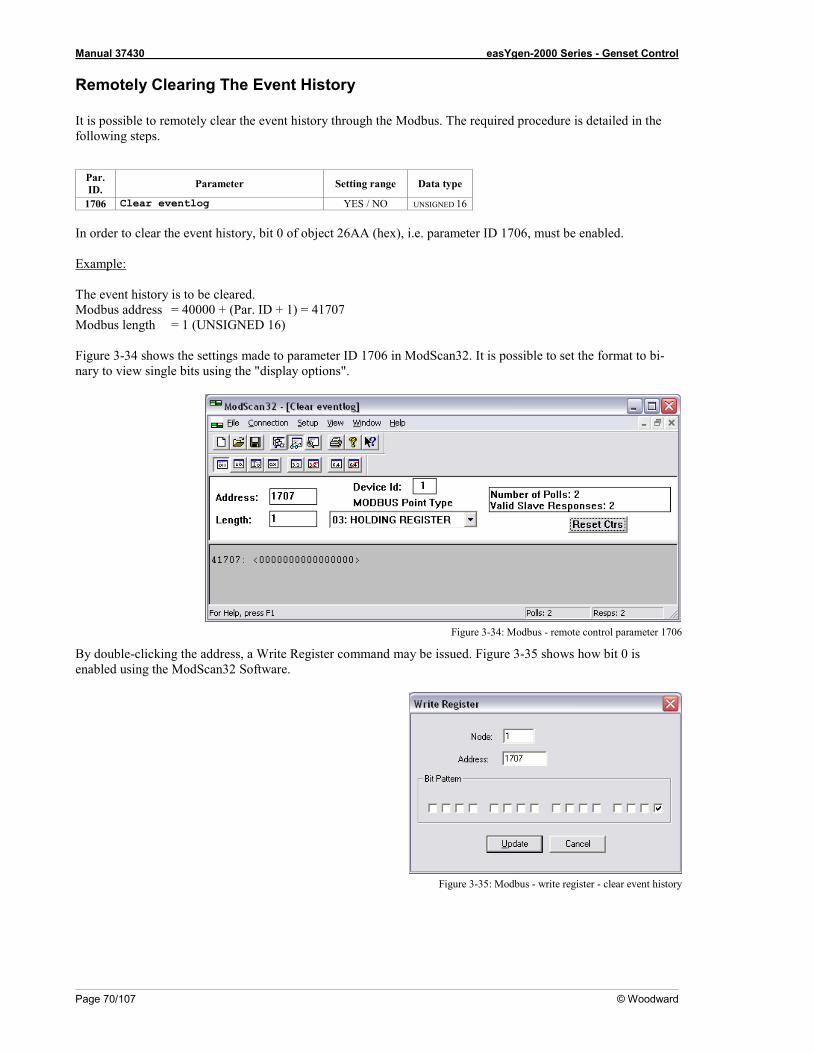
Manual 37430 easYgen-2000 Series - Genset Control
Page 70/107 © Woodward
Remotely Clearing The Event History It is possible to remotely clear the event history through the Modbus. The required procedure is detailed in the following steps.
Par. ID. Parameter Setting range Data type
1706 Clear eventlog YES / NO UNSIGNED 16 In order to clear the event history, bit 0 of object 26AA (hex), i.e. parameter ID 1706, must be enabled. Example: The event history is to be cleared. Modbus address = 40000 + (Par. ID + 1) = 41707 Modbus length = 1 (UNSIGNED 16) Figure 3-34 shows the settings made to parameter ID 1706 in ModScan32. It is possible to set the format to bi-nary to view single bits using the "display options".
Figure 3-34: Modbus - remote control parameter 1706
By double-clicking the address, a Write Register command may be issued. Figure 3-35 shows how bit 0 is enabled using the ModScan32 Software.
Figure 3-35: Modbus - write register - clear event history
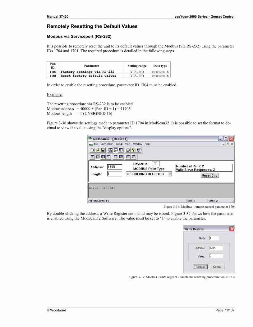
Manual 37430 easYgen-2000 Series - Genset Control
© Woodward Page 71/107
Remotely Resetting the Default Values
Modbus via Serviceport (RS-232)
It is possible to remotely reset the unit to its default values through the Modbus (via RS-232) using the parameter IDs 1704 and 1701. The required procedure is detailed in the following steps.
Par. ID. Parameter Setting range Data type
1704 Factory settings via RS-232 YES / NO UNSIGNED 16 1701 Reset factory default values YES / NO UNSIGNED 16
In order to enable the resetting procedure, parameter ID 1704 must be enabled. Example: The resetting procedure via RS-232 is to be enabled. Modbus address = 40000 + (Par. ID + 1) = 41705 Modbus length = 1 (UNSIGNED 16) Figure 3-36 shows the settings made to parameter ID 1704 in ModScan32. It is possible to set the format to de-cimal to view the value using the "display options".
Figure 3-36: Modbus - remote control parameter 1704
By double-clicking the address, a Write Register command may be issued. Figure 3-37 shows how the parameter is enabled using the ModScan32 Software. The value must be set to "1" to enable the parameter.
Figure 3-37: Modbus - write register - enable the resetting procedure via RS-232
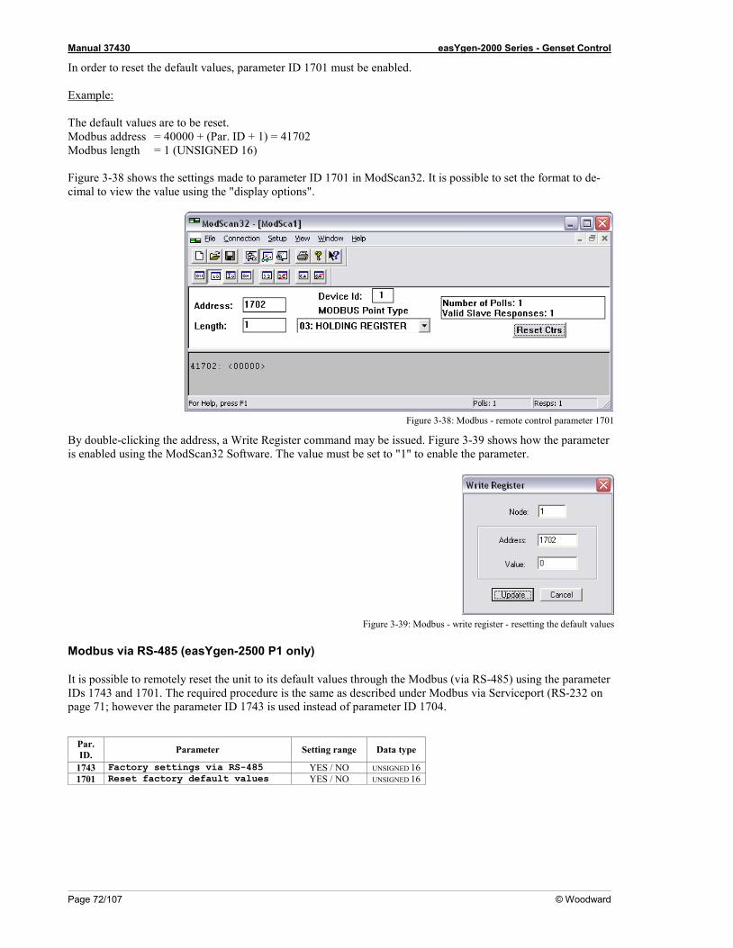
Manual 37430 easYgen-2000 Series - Genset Control
Page 72/107 © Woodward
In order to reset the default values, parameter ID 1701 must be enabled. Example: The default values are to be reset. Modbus address = 40000 + (Par. ID + 1) = 41702 Modbus length = 1 (UNSIGNED 16) Figure 3-38 shows the settings made to parameter ID 1701 in ModScan32. It is possible to set the format to de-cimal to view the value using the "display options".
Figure 3-38: Modbus - remote control parameter 1701
By double-clicking the address, a Write Register command may be issued. Figure 3-39 shows how the parameter is enabled using the ModScan32 Software. The value must be set to "1" to enable the parameter.
Figure 3-39: Modbus - write register - resetting the default values
Modbus via RS-485 (easYgen-2500 P1 only)
It is possible to remotely reset the unit to its default values through the Modbus (via RS-485) using the parameter IDs 1743 and 1701. The required procedure is the same as described under Modbus via Serviceport (RS-232 on page 71; however the parameter ID 1743 is used instead of parameter ID 1704.
Par. ID. Parameter Setting range Data type
1743 Factory settings via RS-485 YES / NO UNSIGNED 16 1701 Reset factory default values YES / NO UNSIGNED 16
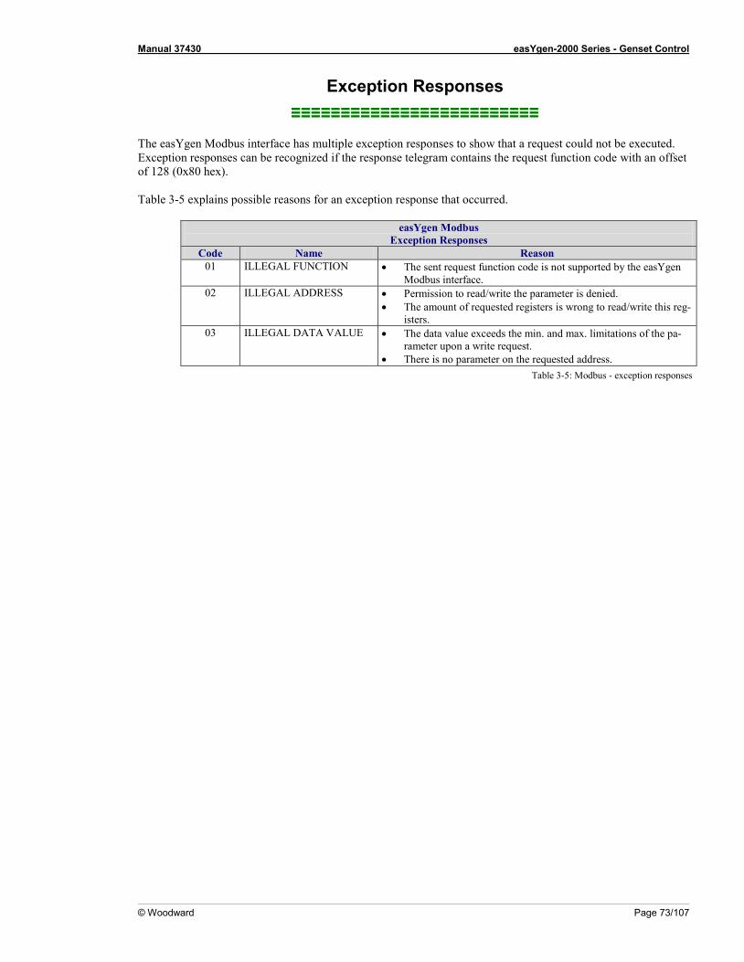
Manual 37430 easYgen-2000 Series - Genset Control
© Woodward Page 73/107
Exception Responses ≡≡≡≡≡≡≡≡≡≡≡≡≡≡≡≡≡≡≡≡≡≡≡≡≡
The easYgen Modbus interface has multiple exception responses to show that a request could not be executed. Exception responses can be recognized if the response telegram contains the request function code with an offset of 128 (0x80 hex). Table 3-5 explains possible reasons for an exception response that occurred.
easYgen Modbus Exception Responses
Code Name Reason 01 ILLEGAL FUNCTION • The sent request function code is not supported by the easYgen
Modbus interface. 02 ILLEGAL ADDRESS • Permission to read/write the parameter is denied.
• The amount of requested registers is wrong to read/write this reg-isters.
03 ILLEGAL DATA VALUE • The data value exceeds the min. and max. limitations of the pa-rameter upon a write request.
• There is no parameter on the requested address. Table 3-5: Modbus - exception responses
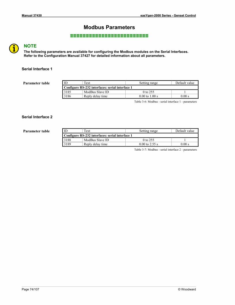
Manual 37430 easYgen-2000 Series - Genset Control
Page 74/107 © Woodward
Modbus Parameters ≡≡≡≡≡≡≡≡≡≡≡≡≡≡≡≡≡≡≡≡≡≡≡≡≡
NOTE The following parameters are available for configuring the Modbus modules on the Serial Interfaces. Refer to the Configuration Manual 37427 for detailed information about all parameters.
Serial Interface 1
Parameter table ID Text Setting range Default value
Configure RS-232 interfaces: serial interface 1 3185 ModBus Slave ID 0 to 255 1 3186 Reply delay time 0.00 to 1.00 s 0.00 s
Table 3-6: Modbus - serial interface 1 - parameters
Serial Interface 2
Parameter table ID Text Setting range Default value
Configure RS-232 interfaces: serial interface 1 3188 ModBus Slave ID 0 to 255 1 3189 Reply delay time 0.00 to 2.55 s 0.00 s
Table 3-7: Modbus - serial interface 2 - parameters
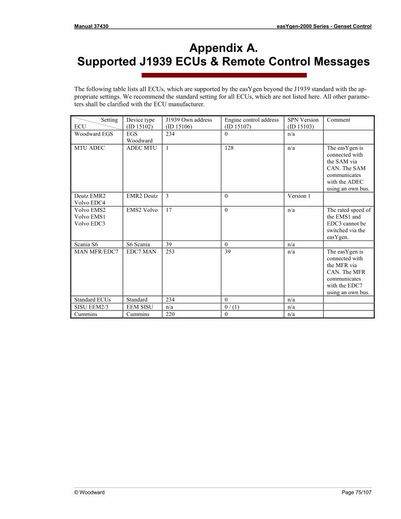
Manual 37430 easYgen-2000 Series - Genset Control
© Woodward Page 75/107
Appendix A. Supported J1939 ECUs & Remote Control Messages
The following table lists all ECUs, which are supported by the easYgen beyond the J1939 standard with the ap-propriate settings. We recommend the standard setting for all ECUs, which are not listed here. All other parame-ters shall be clarified with the ECU manufacturer. Setting ECU
Device type (ID 15102)
J1939 Own address (ID 15106)
Engine control address (ID 15107)
SPN Version (ID 15103)
Comment
Woodward EGS EGS Woodward
234 0 n/a
MTU ADEC ADEC MTU 1 128 n/a The easYgen is connected with the SAM via CAN. The SAM communicates with the ADEC using an own bus.
Deutz EMR2 Volvo EDC4
EMR2 Deutz 3 0 Version 1
Volvo EMS2 Volvo EMS1 Volvo EDC3
EMS2 Volvo 17 0 n/a The rated speed of the EMS1 and EDC3 cannot be switched via the easYgen.
Scania S6 S6 Scania 39 0 n/a MAN MFR/EDC7 EDC7 MAN 253 39 n/a The easYgen is
connected with the MFR via CAN. The MFR communicates with the EDC7 using an own bus.
Standard ECUs Standard 234 0 n/a SISU EEM2/3 EEM SISU n/a 0 / (1) n/a Cummins Cummins 220 0 n/a
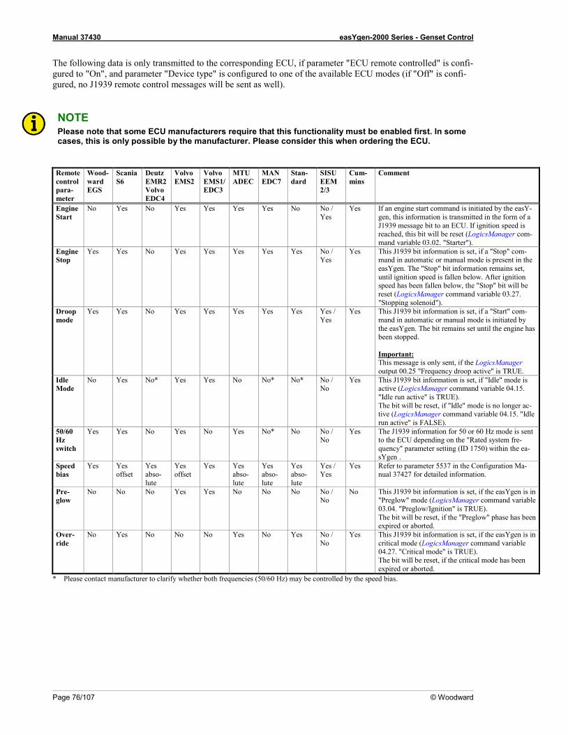
Manual 37430 easYgen-2000 Series - Genset Control
Page 76/107 © Woodward
The following data is only transmitted to the corresponding ECU, if parameter "ECU remote controlled" is confi-gured to "On", and parameter "Device type" is configured to one of the available ECU modes (if "Off" is confi-gured, no J1939 remote control messages will be sent as well).
NOTE Please note that some ECU manufacturers require that this functionality must be enabled first. In some cases, this is only possible by the manufacturer. Please consider this when ordering the ECU.
Remote control para-meter
Wood-ward EGS
Scania S6
Deutz EMR2 Volvo EDC4
Volvo EMS2
Volvo EMS1/ EDC3
MTU ADEC
MAN EDC7
Stan-dard
SISU EEM 2/3
Cum-mins
Comment
Engine Start
No Yes No Yes Yes Yes Yes No No / Yes
Yes If an engine start command is initiated by the easY-gen, this information is transmitted in the form of a J1939 message bit to an ECU. If ignition speed is reached, this bit will be reset (LogicsManager com-mand variable 03.02. "Starter").
Engine Stop
Yes Yes No Yes Yes Yes Yes Yes No / Yes
Yes This J1939 bit information is set, if a "Stop" com-mand in automatic or manual mode is present in the easYgen. The "Stop" bit information remains set, until ignition speed is fallen below. After ignition speed has been fallen below, the "Stop" bit will be reset (LogicsManager command variable 03.27. "Stopping solenoid").
Droop mode
Yes Yes No Yes Yes Yes Yes Yes Yes / Yes
Yes This J1939 bit information is set, if a "Start" com-mand in automatic or manual mode is initiated by the easYgen. The bit remains set until the engine has been stopped. Important: This message is only sent, if the LogicsManager output 00.25 "Frequency droop active" is TRUE.
Idle Mode
No Yes No* Yes Yes No No* No* No / No
Yes This J1939 bit information is set, if "Idle" mode is active (LogicsManager command variable 04.15. "Idle run active" is TRUE). The bit will be reset, if "Idle" mode is no longer ac-tive (LogicsManager command variable 04.15. "Idle run active" is FALSE).
50/60 Hz switch
Yes Yes No Yes No Yes No* No No / No
Yes The J1939 information for 50 or 60 Hz mode is sent to the ECU depending on the "Rated system fre-quency" parameter setting (ID 1750) within the ea-sYgen .
Speed bias
Yes Yes offset
Yes abso-lute
Yes offset
Yes Yes abso-lute
Yes abso-lute
Yes abso-lute
Yes / Yes
Yes Refer to parameter 5537 in the Configuration Ma-nual 37427 for detailed information.
Pre-glow
No No No Yes Yes No No No No / No
No This J1939 bit information is set, if the easYgen is in "Preglow" mode (LogicsManager command variable 03.04. "Preglow/Ignition" is TRUE). The bit will be reset, if the "Preglow" phase has been expired or aborted.
Over-ride
No Yes No No No Yes No Yes No / No
Yes This J1939 bit information is set, if the easYgen is in critical mode (LogicsManager command variable 04.27. "Critical mode" is TRUE). The bit will be reset, if the critical mode has been expired or aborted.
* Please contact manufacturer to clarify whether both frequencies (50/60 Hz) may be controlled by the speed bias.

Manual 37430 easYgen-2000 Series - Genset Control
© Woodward Page 77/107
Appendix B. Data Protocols
Data Protocol 5100 ≡≡≡≡≡≡≡≡≡≡≡≡≡≡≡≡≡≡≡≡≡≡≡≡≡
Modbus CAN Parameter
ID Description Multiplier Units
Modicon start addr.
Start addr. (*1)
Data byte 0 (Mux)
Data byte
450001 450000 0 1,2 Protocoll-ID, allways 5100 --
450002 450001 0 3,4 10100 Pickup speed 1 rpm
450003 450002 0 5,6 - Control mode (STOP/AUTO/MANUALLY)
Mask:000Fh (enum.)
450004 450003 1 1,2 160 Gen. powerfactor 0.001
450005 450004 1 3,4,5,6 170 Av. Gen. Wye-Voltage 0.1 V
450007 450006 2 1,2 144 Gen. frequency 0.01 Hz
450008 450007 2 3,4,5,6 171 Av. Gen. Delta-Voltage 0.1 V
450010 450009 3 1,2 147 Mains / Busbar frequency 0.01 Hz
450011 450010 3 3,4,5,6 173 Av. Mains / Busbar Wye-Voltage
0.1 V
450013 450012 4 1,2 208 Mains / Busbar power fac-tor
0.001
450014 450013 4 3,4,5,6 174 Av. Mains / Busbar Delta-Voltage
0.1 V
450016 450015 5 1,2 2540 Engine, number of start requests
1
450017 450016 5 3,4,5,6 135 Total gen. power 1 W
450019 450018 6 1,2 10202 Operation modes (enum.)
450020 450019 6 3,4,5,6 140 Total mains power 1 W
450022 450021 7 1,2 10110 Battery voltage 0.1 V
450023 450022 7 3,4,5,6 207 Av. Mains Current 0.001 A
450025 450024 8 1,2 10111 Analog input 1 changeable
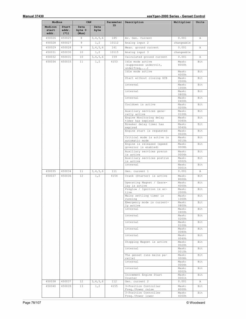
Manual 37430 easYgen-2000 Series - Genset Control
Page 78/107 © Woodward
Modbus CAN Parameter ID
Description Multiplier Units
Modicon start addr.
Start addr. (*1)
Data byte 0 (Mux)
Data byte
450026 450025 8 3,4,5,6 185 Av. Gen. Current 0.001 A
450028 450027 9 1,2 10112 Analog input 2 changeable
450029 450028 9 3,4,5,6 161 Meas. ground current 0.001 A
450031 450030 10 1,2 10115 Analog input 3 changeable
450032 450031 10 3,4,5,6 159 Calculated ground current 0.001 A
450034 450033 11 1,2 4153 Idle mode active (suppresses undervolt, underfreq,...)
Mask: 8000h
Bit
Idle mode active Mask: 4000h
Bit
Start without closing GCB Mask: 2000h
Bit
internal Mask: 1000h
Bit
internal Mask: 0800h
Bit
internal Mask: 0400h
Bit
Cooldown is active Mask: 0200h
Bit
Auxiliary services gene-rally active
Mask: 0100h
Bit
Engine Monitoring delay timer has expired
Mask: 0080h
Bit
Breaker delay timer has expired
Mask: 0040h
Bit
Engine start is requested Mask: 0020h
Bit
Critical mode is active in automatic mode
Mask: 0010h
Bit
Engine is released (speed governor is enabled)
Mask: 0008h
Bit
Auxiliary services prerun is active
Mask: 0004h
Bit
Auxiliary services postrun is active
Mask: 0002h
Bit
internal Mask: 0001h
Bit
450035 450034 11 3,4,5,6 111 Gen. current 1 0.001 A
450037 450036 12 1,2 4154 Crank (Starter) is active Mask: 8000h
Bit
Operating Magnet / Gasre-lay is active
Mask: 4000h
Bit
Preglow / Ignition is ac-tive
Mask: 2000h
Bit
Mains settling timer is running
Mask: 1000h
Bit
Emergency mode is current-ly active
Mask: 0800h
Bit
internal Mask: 0400h
Bit
internal Mask: 0200h
Bit
internal Mask: 0100h
Bit
internal Mask: 0080h
Bit
internal Mask: 0040h
Bit
Stopping Magnet is active Mask: 0020h
Bit
internal Mask: 0010h
Bit
The genset runs mains pa-rallel
Mask: 0008h
Bit
internal Mask: 0004h
Bit
internal Mask: 0002h
Bit
Increment Engine Start Counter
Mask: 0001h
Bit
450038 450037 12 3,4,5,6 112 Gen. current 2 0.001 A
450040 450039 13 1,2 4155 3-Position Controller Freq./Power raise
Mask: 8000h
Bit
3-Position Controller Freq./Power lower
Mask: 4000h
Bit

Manual 37430 easYgen-2000 Series - Genset Control
© Woodward Page 79/107
Modbus CAN Parameter ID
Description Multiplier Units
Modicon start addr.
Start addr. (*1)
Data byte 0 (Mux)
Data byte
3-Position Controller Volt./ReactPow raise
Mask: 2000h
Bit
3-Position Controller Volt./ReactPow lower
Mask: 1000h
Bit
GCB is closed Mask: 0800h
Bit
MCB is closed Mask: 0400h
Bit
internal Mask: 0200h
Bit
Synchronisation GCB is ac-tive
Mask: 0100h
Bit
Opening GCB is active Mask: 0080h
Bit
Closing GCB is active Mask: 0040h
Bit
Synchronisation MCB is ac-tive
Mask: 0020h
Bit
Opening MCB is active Mask: 0010h
Bit
Closing MCB is active Mask: 0008h
Bit
Unloading generator is ac-tive
Mask: 0004h
Bit
Unloading mains is active Mask: 0002h
Bit
Power limited prerun Mask: 0001h
Bit
450041 450040 13 3,4,5,6 113 Gen. current 3 0.001 A
450043 450042 14 1,2 4156 internal Mask: 8000h
Bit
internal Mask: 4000h
Bit
internal Mask: 2000h
Bit
internal Mask: 1000h
Bit
internal Mask: 0800h
Bit
Dead busbar closure re-quest for GCB or MCB
Mask: 0400h
Bit
Active power load share is acitve
Mask: 0200h
Bit
Reactive power load share is acitve
Mask: 0100h
Bit
Generator with a closed GCB is requested
Mask: 0080h
Bit
LDSS: The Engine is started
Mask: 0040h
Bit
LDSS: The Engine is stopped
Mask: 0020h
Bit
LDSS: The Engine is stopped, if possible
Mask: 0010h
Bit
LDSS: Minimum Running Time is active
Mask: 0008h
Bit
LDSS: The LDSS function is active
Mask: 0004h
Bit
The Critical Mode Postrun is active
Mask: 0002h
Bit
internal Mask: 0001h
Bit
450044 450043 14 3,4,5,6 134 Mains current L1 0.001 A
450046 450045 15 1,2 10131 internal Mask: 0040h
Bit
Alarm class F latched Mask: 0020h
Bit
Alarm class E latched Mask: 0010h
Bit
Alarm class D latched Mask: 0008h
Bit
Alarm class C latched Mask: 0004h
Bit
Alarm class B latched Mask: 0002h
Bit
Alarm class A latched Mask: 0001h
Bit
450047 450046 15 3,4,5,6 136 Total gen. reactive power 1 var
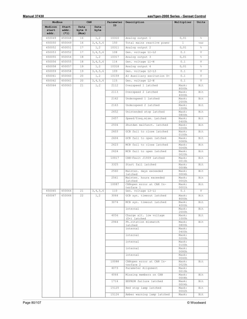
Manual 37430 easYgen-2000 Series - Genset Control
Page 80/107 © Woodward
Modbus CAN Parameter ID
Description Multiplier Units
Modicon start addr.
Start addr. (*1)
Data byte 0 (Mux)
Data byte
450049 450048 16 1,2 10310 Analog output 1 0,01 %
450050 450049 16 3,4,5,6 150 Total mains reactive power 1 var
450052 450051 17 1,2 10311 Analog output 2 0,01 %
450053 450052 17 3,4,5,6 108 Gen. voltage L1-L2 0.1 V
450055 450054 18 1,2 10317 Analog output 3 0,01 %
450056 450055 18 3,4,5,6 114 Gen. voltage L1-N 0.1 V
450058 450057 19 1,2 10318 Analog output 4 0,01 %
450059 450058 19 3,4,5,6 109 Gen. voltage L2-L3 0.1 V
450061 450060 20 1,2 10159 AI Auxiliary excitation D+ 0.1 V
450062 450061 20 3,4,5,6 115 Gen. voltage L2-N 0.1 V
450064 450063 21 1,2 2112 Overspeed 1 latched Mask: 8000h
Bit
2113 Overspeed 2 latched Mask: 4000h
Bit
2162 Underspeed 1 latched Mask: 2000h
Bit
2163 Underspeed 2 latched Mask: 1000h
Bit
2652 Unintended stop latched Mask: 0800h
Bit
2457 Speed/freq.mism. Latched Mask: 0400h
Bit
2504 Shutdwn malfunct. latched Mask: 0200h
Bit
2603 GCB fail to close latched Mask: 0100h
Bit
2604 GCB fail to open latched Mask: 0080h
Bit
2623 MCB fail to close latched Mask: 0040h
Bit
2624 MCB fail to open latched Mask: 0020h
Bit
10017 CAN-Fault J1939 latched Mask: 0010h
Bit
3325 Start fail latched Mask: 0008h
Bit
2560 Mainten. days exceeded latched
Mask: 0004h
Bit
2561 Mainten. hours exceeded latched
Mask: 0002h
Bit
10087 CANopen error at CAN In-terface 1
Mask: 0001h
Bit
450065 450064 21 3,4,5,6 110 Gen. voltage L3-L1 0.1 V
450067 450066 22 1,2 3064 GCB syn. timeout latched Mask: 8000h
Bit
3074 MCB syn. timeout latched Mask: 4000h
Bit
internal Mask: 2000h
Bit
4056 Charge alt. low voltage (D+) latched
Mask: 1000h
Bit
2944 Ph.rotation mismatch latched
Mask: 0800h
Bit
internal Mask: 0400h
internal Mask: 0200h
internal Mask: 0100h
internal Mask: 0080h
internal Mask: 0040h
10088 CANopen error at CAN In-terface 2
Mask: 0020h
Bit
4073 Parameter Alignment Mask: 0010h
4064 Missing members on CAN Mask: 0008h
Bit
1714 EEPROM failure latched Mask: 0004h
Bit
15125 Red stop lamp latched Mask: 0002h
Bit
15126 Amber warning lamp latched Mask: Bit

Manual 37430 easYgen-2000 Series - Genset Control
© Woodward Page 81/107
Modbus CAN Parameter ID
Description Multiplier Units
Modicon start addr.
Start addr. (*1)
Data byte 0 (Mux)
Data byte
0001h
450068 450067 22 3,4,5,6 116 Gen. voltage L3-N 0.1 V
450070 450069 23 1,2 2558 Hours until next mainte-nance
1 h
450071 450070 23 3,4,5,6 118 Mains / Busbar voltage L1-L2
0.1 V
450073 450072 24 1,2 1912 Gen.overfreq. 1 latched Mask: 8000h
Bit
1913 Gen.overfreq. 2 latched Mask: 4000h
Bit
1962 Gen.underfreq. 1 latched Mask: 2000h
Bit
1963 Gen.underfreq. 2 latched Mask: 1000h
Bit
2012 Gen.overvolt. 1 latched Mask: 0800h
Bit
2013 Gen.overvolt. 2 latched Mask: 0400h
Bit
2062 Gen.undervolt. 1 latched Mask: 0200h
Bit
2063 Gen.undervolt. 2 latched Mask: 0100h
Bit
2218 Gen. overcurr. 1 latched Mask: 0080h
Bit
2219 Gen. overcurr. 2 latched Mask: 0040h
Bit
2220 Gen. overcurr. 3 latched Mask: 0020h
Bit
2262 Gen. Rv/Rd pow.1 latched Mask: 0010h
Bit
2263 Gen. Rv/Rd pow.2 latched Mask: 0008h
Bit
2314 Gen. Overload IOP 1 latched
Mask: 0004h
Bit
2315 Gen. Overload IOP 2 latched
Mask: 0002h
Bit
internal Mask: 0001h
Bit
450074 450073 24 3,4,5,6 121 Mains / Busbar voltage L1-N
0.1 V
450076 450075 25 1,2 2412 Unbal. load 1 latched Mask: 8000h
Bit
2413 Unbal. load 2 latched Mask: 4000h
Bit
3907 Gen. Asymmetry latched Mask: 2000h
Bit
3263 Ground fault 1 latched Mask: 1000h
Bit
3264 Ground fault 2 latched Mask: 0800h
Bit
3955 Gen. phase rot. misw. Latched
Mask: 0400h
Bit
2924 Gen act.pwr mismatch Latched
Mask: 0200h
Bit
3124 Gen. unloading fault Latched
Mask: 0100h
Bit
4038 Inv.time ov.curr. Latched Mask: 0080h
Bit
2664 Operating range failed, latched
Mask: 0040h
Bit
2362 Gen. Overload MOP 1 latched
Mask: 0020h
Bit
2363 Gen. Overload MOP 2 latched
Mask: 0010h
Bit
2337 Gen. overexcited 1 latched Mask: 0008h
Bit
2338 Gen. overexcited 2 latched Mask: 0004h
Bit
2387 Gen. underexcited 1 latched
Mask: 0002h
Bit
2388 Gen. underexcited 2 latched
Mask: 0001h
Bit
450077 450076 25 3,4,5,6 119 Mains / Busbar voltage L2-L3
0.1 V
450079 450078 26 1,2 2862 Mains / Busbar ov.freq. 1 latched
Mask: 8000h
Bit
2863 Mains / Busbar ov.freq. 2 latched
Mask: 4000h
Bit
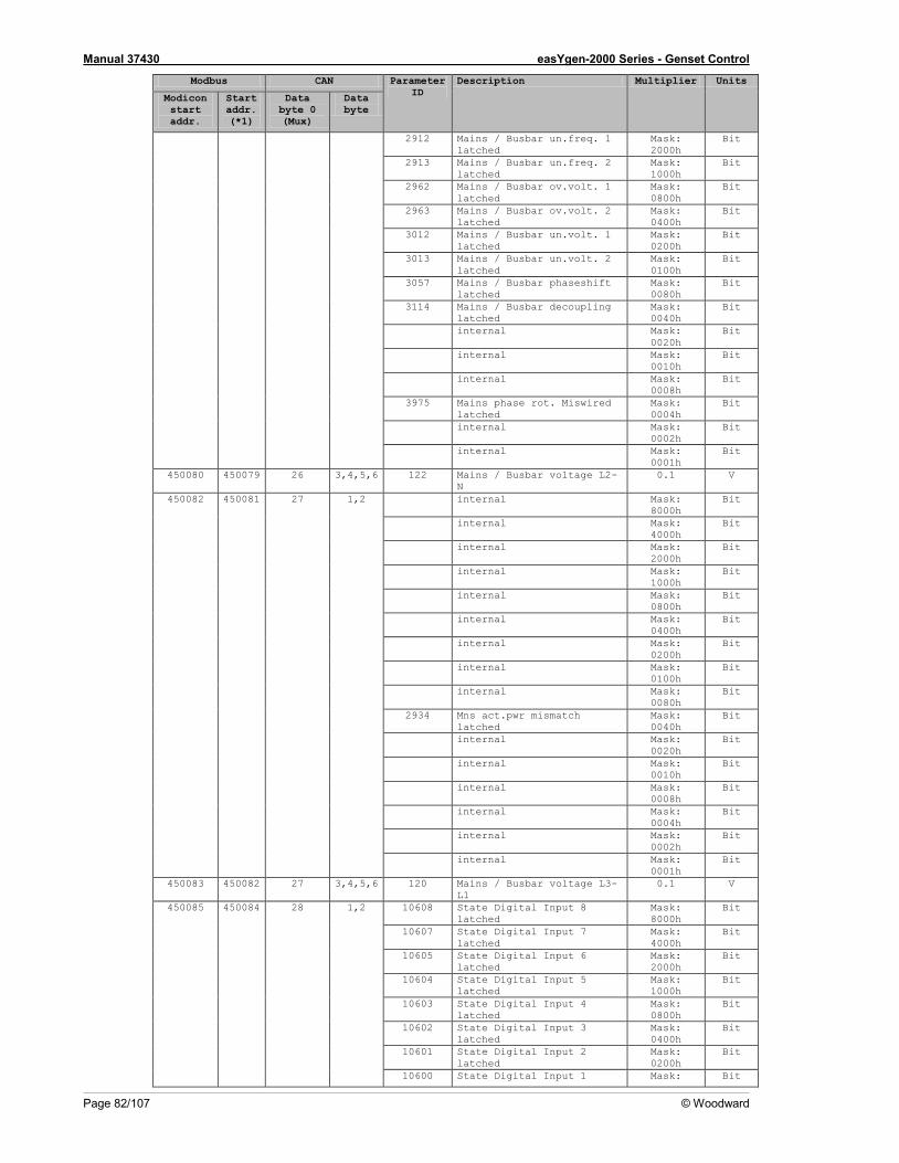
Manual 37430 easYgen-2000 Series - Genset Control
Page 82/107 © Woodward
Modbus CAN Parameter ID
Description Multiplier Units
Modicon start addr.
Start addr. (*1)
Data byte 0 (Mux)
Data byte
2912 Mains / Busbar un.freq. 1 latched
Mask: 2000h
Bit
2913 Mains / Busbar un.freq. 2 latched
Mask: 1000h
Bit
2962 Mains / Busbar ov.volt. 1 latched
Mask: 0800h
Bit
2963 Mains / Busbar ov.volt. 2 latched
Mask: 0400h
Bit
3012 Mains / Busbar un.volt. 1 latched
Mask: 0200h
Bit
3013 Mains / Busbar un.volt. 2 latched
Mask: 0100h
Bit
3057 Mains / Busbar phaseshift latched
Mask: 0080h
Bit
3114 Mains / Busbar decoupling latched
Mask: 0040h
Bit
internal Mask: 0020h
Bit
internal Mask: 0010h
Bit
internal Mask: 0008h
Bit
3975 Mains phase rot. Miswired latched
Mask: 0004h
Bit
internal Mask: 0002h
Bit
internal Mask: 0001h
Bit
450080 450079 26 3,4,5,6 122 Mains / Busbar voltage L2-N
0.1 V
450082 450081 27 1,2 internal Mask: 8000h
Bit
internal Mask: 4000h
Bit
internal Mask: 2000h
Bit
internal Mask: 1000h
Bit
internal Mask: 0800h
Bit
internal Mask: 0400h
Bit
internal Mask: 0200h
Bit
internal Mask: 0100h
Bit
internal Mask: 0080h
Bit
2934 Mns act.pwr mismatch latched
Mask: 0040h
Bit
internal Mask: 0020h
Bit
internal Mask: 0010h
Bit
internal Mask: 0008h
Bit
internal Mask: 0004h
Bit
internal Mask: 0002h
Bit
internal Mask: 0001h
Bit
450083 450082 27 3,4,5,6 120 Mains / Busbar voltage L3-L1
0.1 V
450085 450084 28 1,2 10608 State Digital Input 8 latched
Mask: 8000h
Bit
10607 State Digital Input 7 latched
Mask: 4000h
Bit
10605 State Digital Input 6 latched
Mask: 2000h
Bit
10604 State Digital Input 5 latched
Mask: 1000h
Bit
10603 State Digital Input 4 latched
Mask: 0800h
Bit
10602 State Digital Input 3 latched
Mask: 0400h
Bit
10601 State Digital Input 2 latched
Mask: 0200h
Bit
10600 State Digital Input 1 Mask: Bit
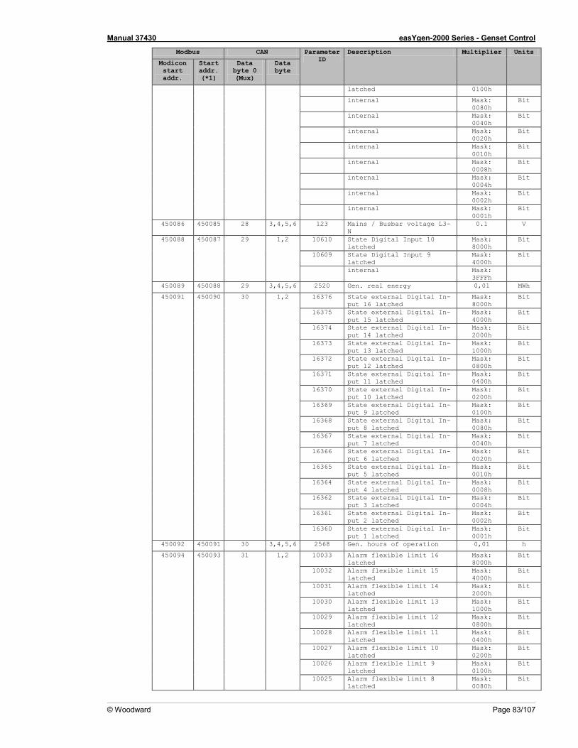
Manual 37430 easYgen-2000 Series - Genset Control
© Woodward Page 83/107
Modbus CAN Parameter ID
Description Multiplier Units
Modicon start addr.
Start addr. (*1)
Data byte 0 (Mux)
Data byte
latched 0100h
internal Mask: 0080h
Bit
internal Mask: 0040h
Bit
internal Mask: 0020h
Bit
internal Mask: 0010h
Bit
internal Mask: 0008h
Bit
internal Mask: 0004h
Bit
internal Mask: 0002h
Bit
internal Mask: 0001h
Bit
450086 450085 28 3,4,5,6 123 Mains / Busbar voltage L3-N
0.1 V
450088 450087 29 1,2 10610 State Digital Input 10 latched
Mask: 8000h
Bit
10609 State Digital Input 9 latched
Mask: 4000h
Bit
internal Mask: 3FFFh
450089 450088 29 3,4,5,6 2520 Gen. real energy 0,01 MWh
450091 450090 30 1,2 16376 State external Digital In-put 16 latched
Mask: 8000h
Bit
16375 State external Digital In-put 15 latched
Mask: 4000h
Bit
16374 State external Digital In-put 14 latched
Mask: 2000h
Bit
16373 State external Digital In-put 13 latched
Mask: 1000h
Bit
16372 State external Digital In-put 12 latched
Mask: 0800h
Bit
16371 State external Digital In-put 11 latched
Mask: 0400h
Bit
16370 State external Digital In-put 10 latched
Mask: 0200h
Bit
16369 State external Digital In-put 9 latched
Mask: 0100h
Bit
16368 State external Digital In-put 8 latched
Mask: 0080h
Bit
16367 State external Digital In-put 7 latched
Mask: 0040h
Bit
16366 State external Digital In-put 6 latched
Mask: 0020h
Bit
16365 State external Digital In-put 5 latched
Mask: 0010h
Bit
16364 State external Digital In-put 4 latched
Mask: 0008h
Bit
16362 State external Digital In-put 3 latched
Mask: 0004h
Bit
16361 State external Digital In-put 2 latched
Mask: 0002h
Bit
16360 State external Digital In-put 1 latched
Mask: 0001h
Bit
450092 450091 30 3,4,5,6 2568 Gen. hours of operation 0,01 h
450094 450093 31 1,2 10033 Alarm flexible limit 16 latched
Mask: 8000h
Bit
10032 Alarm flexible limit 15 latched
Mask: 4000h
Bit
10031 Alarm flexible limit 14 latched
Mask: 2000h
Bit
10030 Alarm flexible limit 13 latched
Mask: 1000h
Bit
10029 Alarm flexible limit 12 latched
Mask: 0800h
Bit
10028 Alarm flexible limit 11 latched
Mask: 0400h
Bit
10027 Alarm flexible limit 10 latched
Mask: 0200h
Bit
10026 Alarm flexible limit 9 latched
Mask: 0100h
Bit
10025 Alarm flexible limit 8 latched
Mask: 0080h
Bit
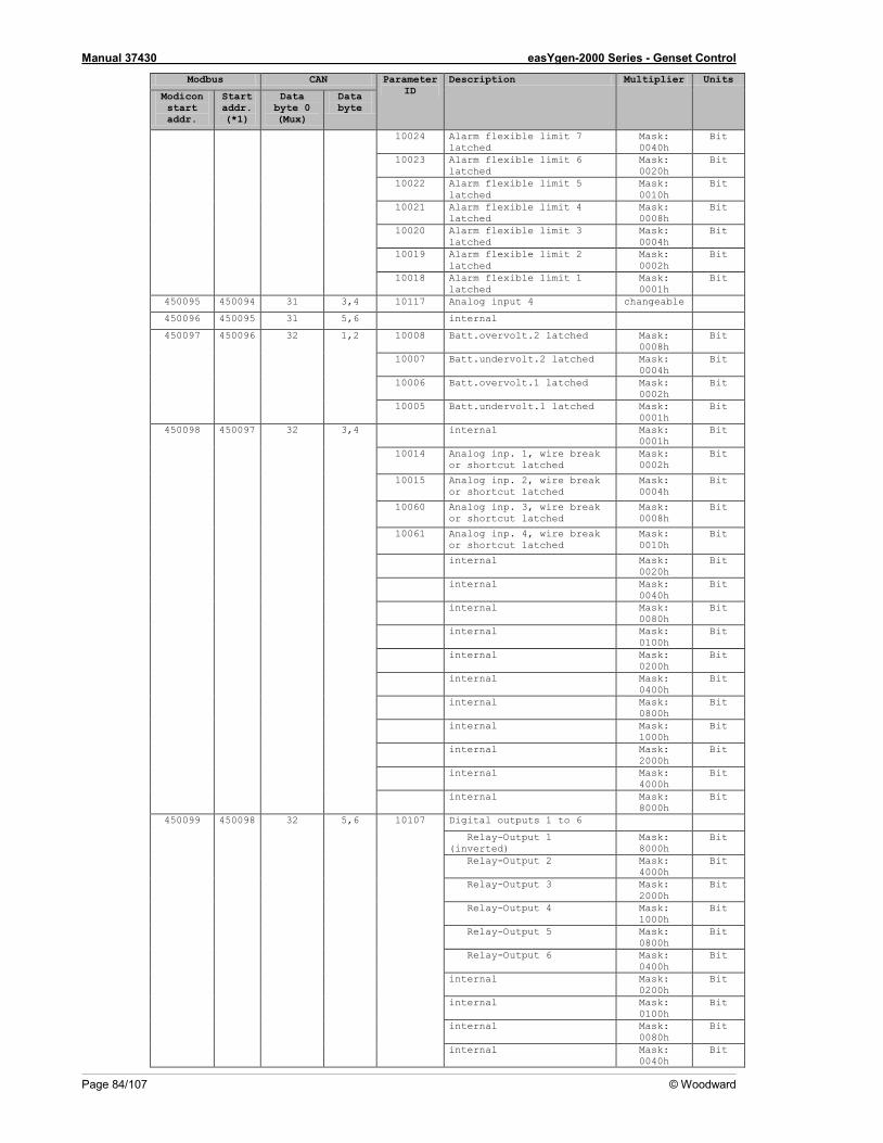
Manual 37430 easYgen-2000 Series - Genset Control
Page 84/107 © Woodward
Modbus CAN Parameter ID
Description Multiplier Units
Modicon start addr.
Start addr. (*1)
Data byte 0 (Mux)
Data byte
10024 Alarm flexible limit 7 latched
Mask: 0040h
Bit
10023 Alarm flexible limit 6 latched
Mask: 0020h
Bit
10022 Alarm flexible limit 5 latched
Mask: 0010h
Bit
10021 Alarm flexible limit 4 latched
Mask: 0008h
Bit
10020 Alarm flexible limit 3 latched
Mask: 0004h
Bit
10019 Alarm flexible limit 2 latched
Mask: 0002h
Bit
10018 Alarm flexible limit 1 latched
Mask: 0001h
Bit
450095 450094 31 3,4 10117 Analog input 4 changeable
450096 450095 31 5,6 internal
450097 450096 32 1,2 10008 Batt.overvolt.2 latched Mask: 0008h
Bit
10007 Batt.undervolt.2 latched Mask: 0004h
Bit
10006 Batt.overvolt.1 latched Mask: 0002h
Bit
10005 Batt.undervolt.1 latched Mask: 0001h
Bit
450098 450097 32 3,4 internal Mask: 0001h
Bit
10014 Analog inp. 1, wire break or shortcut latched
Mask: 0002h
Bit
10015 Analog inp. 2, wire break or shortcut latched
Mask: 0004h
Bit
10060 Analog inp. 3, wire break or shortcut latched
Mask: 0008h
Bit
10061 Analog inp. 4, wire break or shortcut latched
Mask: 0010h
Bit
internal Mask: 0020h
Bit
internal Mask: 0040h
Bit
internal Mask: 0080h
Bit
internal Mask: 0100h
Bit
internal Mask: 0200h
Bit
internal Mask: 0400h
Bit
internal Mask: 0800h
Bit
internal Mask: 1000h
Bit
internal Mask: 2000h
Bit
internal Mask: 4000h
Bit
internal Mask: 8000h
Bit
450099 450098 32 5,6 10107 Digital outputs 1 to 6
Relay-Output 1 (inverted)
Mask: 8000h
Bit
Relay-Output 2 Mask: 4000h
Bit
Relay-Output 3 Mask: 2000h
Bit
Relay-Output 4 Mask: 1000h
Bit
Relay-Output 5 Mask: 0800h
Bit
Relay-Output 6 Mask: 0400h
Bit
internal Mask: 0200h
Bit
internal Mask: 0100h
Bit
internal Mask: 0080h
Bit
internal Mask: 0040h
Bit
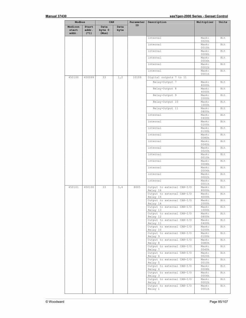
Manual 37430 easYgen-2000 Series - Genset Control
© Woodward Page 85/107
Modbus CAN Parameter ID
Description Multiplier Units
Modicon start addr.
Start addr. (*1)
Data byte 0 (Mux)
Data byte
internal Mask: 0020h
Bit
internal Mask: 0010h
Bit
internal Mask: 0008h
Bit
internal Mask: 0004h
Bit
internal Mask: 0002h
Bit
internal Mask: 0001h
Bit
450100 450099 33 1,2 10109 Digital outputs 7 to 11
Relay-Output 7 Mask: 8000h
Bit
Relay-Output 8 Mask: 4000h
Bit
Relay-Output 9 Mask: 2000h
Bit
Relay-Output 10 Mask: 1000h
Bit
Relay-Output 11 Mask: 0800h
Bit
internal Mask: 0400h
Bit
internal Mask: 0200h
Bit
internal Mask: 0100h
Bit
internal Mask: 0080h
Bit
internal Mask: 0040h
Bit
internal Mask: 0020h
Bit
internal Mask: 0010h
Bit
internal Mask: 0008h
Bit
internal Mask: 0004h
Bit
internal Mask: 0002h
Bit
internal Mask: 0001h
Bit
450101 450100 33 3,4 8005 Output to external CAN-I/O Relay 16
Mask: 8000h
Bit
Output to external CAN-I/O Relay 15
Mask: 4000h
Bit
Output to external CAN-I/O Relay 14
Mask: 2000h
Bit
Output to external CAN-I/O Relay 13
Mask: 1000h
Bit
Output to external CAN-I/O Relay 12
Mask: 0800h
Bit
Output to external CAN-I/O Relay 11
Mask: 0400h
Bit
Output to external CAN-I/O Relay 10
Mask: 0200h
Bit
Output to external CAN-I/O Relay 9
Mask: 0100h
Bit
Output to external CAN-I/O Relay 8
Mask: 0080h
Bit
Output to external CAN-I/O Relay 7
Mask: 0040h
Bit
Output to external CAN-I/O Relay 6
Mask: 0020h
Bit
Output to external CAN-I/O Relay 5
Mask: 0010h
Bit
Output to external CAN-I/O Relay 4
Mask: 0008h
Bit
Output to external CAN-I/O Relay 3
Mask: 0004h
Bit
Output to external CAN-I/O Relay 2
Mask: 0002h
Bit
Output to external CAN-I/O Relay 1
Mask: 0001h
Bit
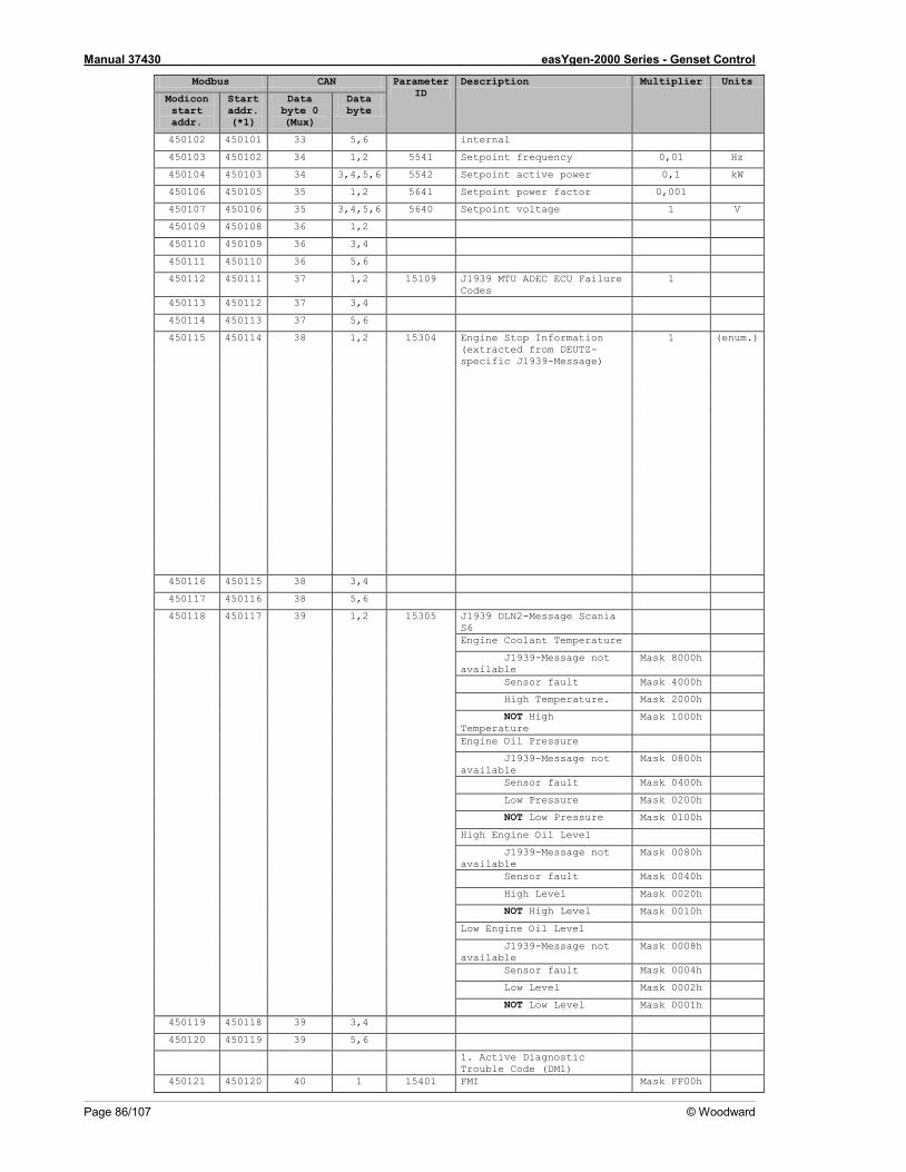
Manual 37430 easYgen-2000 Series - Genset Control
Page 86/107 © Woodward
Modbus CAN Parameter ID
Description Multiplier Units
Modicon start addr.
Start addr. (*1)
Data byte 0 (Mux)
Data byte
450102 450101 33 5,6 internal
450103 450102 34 1,2 5541 Setpoint frequency 0,01 Hz
450104 450103 34 3,4,5,6 5542 Setpoint active power 0,1 kW
450106 450105 35 1,2 5641 Setpoint power factor 0,001
450107 450106 35 3,4,5,6 5640 Setpoint voltage 1 V
450109 450108 36 1,2
450110 450109 36 3,4
450111 450110 36 5,6
450112 450111 37 1,2 15109 J1939 MTU ADEC ECU Failure Codes
1
450113 450112 37 3,4
450114 450113 37 5,6
450115 450114 38 1,2 15304 Engine Stop Information (extracted from DEUTZ-specific J1939-Message)
1 (enum.)
450116 450115 38 3,4
450117 450116 38 5,6
450118 450117 39 1,2 15305 J1939 DLN2-Message Scania S6
Engine Coolant Temperature
J1939-Message not available
Mask 8000h
Sensor fault Mask 4000h
High Temperature. Mask 2000h
NOT High Temperature
Mask 1000h
Engine Oil Pressure
J1939-Message not available
Mask 0800h
Sensor fault Mask 0400h
Low Pressure Mask 0200h
NOT Low Pressure Mask 0100h
High Engine Oil Level
J1939-Message not available
Mask 0080h
Sensor fault Mask 0040h
High Level Mask 0020h
NOT High Level Mask 0010h
Low Engine Oil Level
J1939-Message not available
Mask 0008h
Sensor fault Mask 0004h
Low Level Mask 0002h
NOT Low Level Mask 0001h
450119 450118 39 3,4
450120 450119 39 5,6
1. Active Diagnostic Trouble Code (DM1)
450121 450120 40 1 15401 FMI Mask FF00h
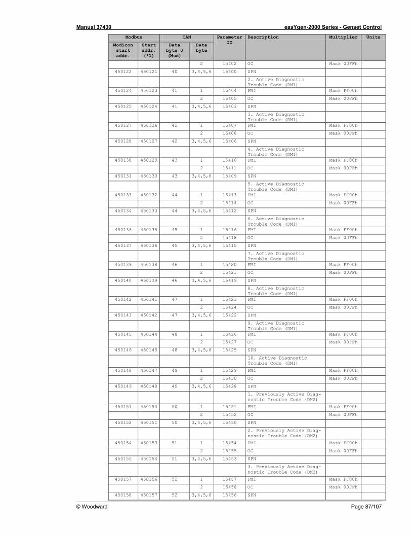
Manual 37430 easYgen-2000 Series - Genset Control
© Woodward Page 87/107
Modbus CAN Parameter ID
Description Multiplier Units
Modicon start addr.
Start addr. (*1)
Data byte 0 (Mux)
Data byte
2 15402 OC Mask 00FFh
450122 450121 40 3,4,5,6 15400 SPN
2. Active Diagnostic Trouble Code (DM1)
450124 450123 41 1 15404 FMI Mask FF00h
2 15405 OC Mask 00FFh
450125 450124 41 3,4,5,6 15403 SPN
3. Active Diagnostic Trouble Code (DM1)
450127 450126 42 1 15407 FMI Mask FF00h
2 15408 OC Mask 00FFh
450128 450127 42 3,4,5,6 15406 SPN
4. Active Diagnostic Trouble Code (DM1)
450130 450129 43 1 15410 FMI Mask FF00h
2 15411 OC Mask 00FFh
450131 450130 43 3,4,5,6 15409 SPN
5. Active Diagnostic Trouble Code (DM1)
450133 450132 44 1 15413 FMI Mask FF00h
2 15414 OC Mask 00FFh
450134 450133 44 3,4,5,6 15412 SPN
6. Active Diagnostic Trouble Code (DM1)
450136 450135 45 1 15416 FMI Mask FF00h
2 15418 OC Mask 00FFh
450137 450136 45 3,4,5,6 15415 SPN
7. Active Diagnostic Trouble Code (DM1)
450139 450138 46 1 15420 FMI Mask FF00h
2 15421 OC Mask 00FFh
450140 450139 46 3,4,5,6 15419 SPN
8. Active Diagnostic Trouble Code (DM1)
450142 450141 47 1 15423 FMI Mask FF00h
2 15424 OC Mask 00FFh
450143 450142 47 3,4,5,6 15422 SPN
9. Active Diagnostic Trouble Code (DM1)
450145 450144 48 1 15426 FMI Mask FF00h
2 15427 OC Mask 00FFh
450146 450145 48 3,4,5,6 15425 SPN
10. Active Diagnostic Trouble Code (DM1)
450148 450147 49 1 15429 FMI Mask FF00h
2 15430 OC Mask 00FFh
450149 450148 49 3,4,5,6 15428 SPN
1. Previously Active Diag-nostic Trouble Code (DM2)
450151 450150 50 1 15451 FMI Mask FF00h
2 15452 OC Mask 00FFh
450152 450151 50 3,4,5,6 15450 SPN
2. Previously Active Diag-nostic Trouble Code (DM2)
450154 450153 51 1 15454 FMI Mask FF00h
2 15455 OC Mask 00FFh
450155 450154 51 3,4,5,6 15453 SPN
3. Previously Active Diag-nostic Trouble Code (DM2)
450157 450156 52 1 15457 FMI Mask FF00h
2 15458 OC Mask 00FFh
450158 450157 52 3,4,5,6 15456 SPN
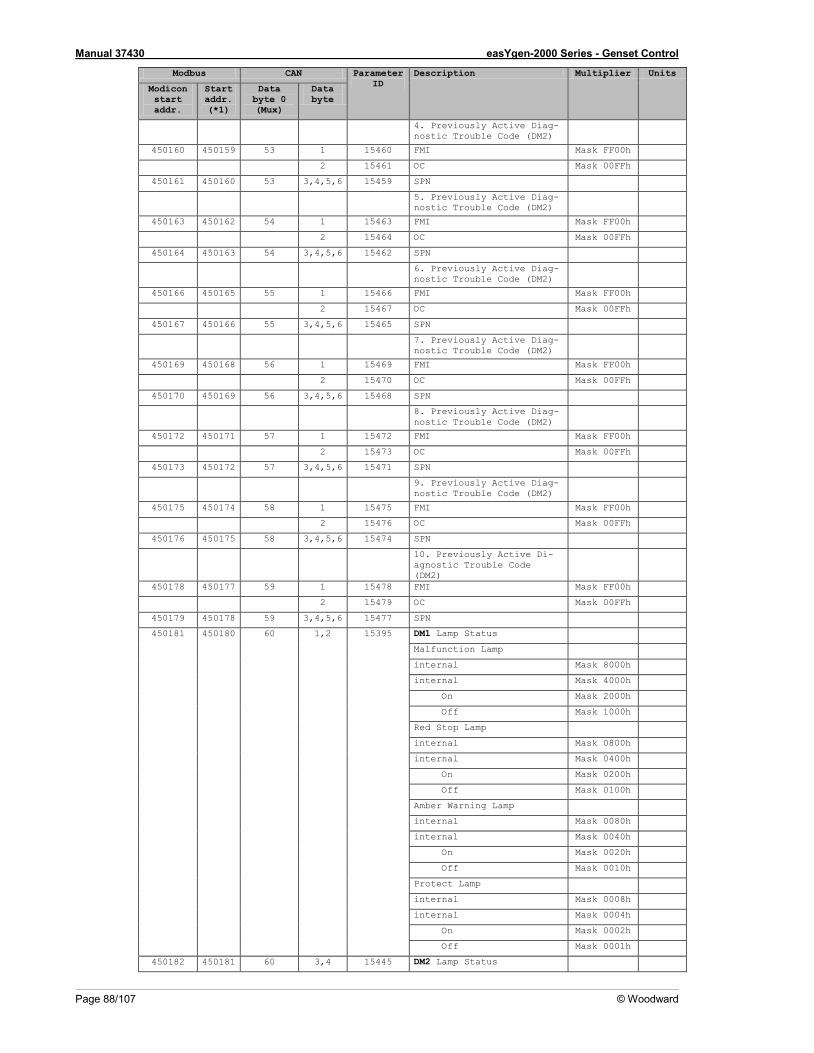
Manual 37430 easYgen-2000 Series - Genset Control
Page 88/107 © Woodward
Modbus CAN Parameter ID
Description Multiplier Units
Modicon start addr.
Start addr. (*1)
Data byte 0 (Mux)
Data byte
4. Previously Active Diag-nostic Trouble Code (DM2)
450160 450159 53 1 15460 FMI Mask FF00h
2 15461 OC Mask 00FFh
450161 450160 53 3,4,5,6 15459 SPN
5. Previously Active Diag-nostic Trouble Code (DM2)
450163 450162 54 1 15463 FMI Mask FF00h
2 15464 OC Mask 00FFh
450164 450163 54 3,4,5,6 15462 SPN
6. Previously Active Diag-nostic Trouble Code (DM2)
450166 450165 55 1 15466 FMI Mask FF00h
2 15467 OC Mask 00FFh
450167 450166 55 3,4,5,6 15465 SPN
7. Previously Active Diag-nostic Trouble Code (DM2)
450169 450168 56 1 15469 FMI Mask FF00h
2 15470 OC Mask 00FFh
450170 450169 56 3,4,5,6 15468 SPN
8. Previously Active Diag-nostic Trouble Code (DM2)
450172 450171 57 1 15472 FMI Mask FF00h
2 15473 OC Mask 00FFh
450173 450172 57 3,4,5,6 15471 SPN
9. Previously Active Diag-nostic Trouble Code (DM2)
450175 450174 58 1 15475 FMI Mask FF00h
2 15476 OC Mask 00FFh
450176 450175 58 3,4,5,6 15474 SPN
10. Previously Active Di-agnostic Trouble Code (DM2)
450178 450177 59 1 15478 FMI Mask FF00h
2 15479 OC Mask 00FFh
450179 450178 59 3,4,5,6 15477 SPN
450181 450180 60 1,2 15395 DM1 Lamp Status
Malfunction Lamp
internal Mask 8000h
internal Mask 4000h
On Mask 2000h
Off Mask 1000h
Red Stop Lamp
internal Mask 0800h
internal Mask 0400h
On Mask 0200h
Off Mask 0100h
Amber Warning Lamp
internal Mask 0080h
internal Mask 0040h
On Mask 0020h
Off Mask 0010h
Protect Lamp
internal Mask 0008h
internal Mask 0004h
On Mask 0002h
Off Mask 0001h
450182 450181 60 3,4 15445 DM2 Lamp Status

Manual 37430 easYgen-2000 Series - Genset Control
© Woodward Page 89/107
Modbus CAN Parameter ID
Description Multiplier Units
Modicon start addr.
Start addr. (*1)
Data byte 0 (Mux)
Data byte
Malfunction Lamp
internal Mask 8000h
internal Mask 4000h
On Mask 2000h
Off Mask 1000h
Red Stop Lamp
internal Mask 0800h
internal Mask 0400h
On Mask 0200h
Off Mask 0100h
Amber Warning Lamp
internal Mask 0080h
internal Mask 0040h
On Mask 0020h
Off Mask 0010h
Protect Lamp
internal Mask 0008h
internal Mask 0004h
On Mask 0002h
Off Mask 0001h
450183 450182 60 5,6 internal
450184 450183 61 1,2 15308 Engine Speed (j1939-EEC1) 1 rpm
450185 450184 61 3,4 15202 Engine Coolant Temperature (J1939-ET1)
1 °C
450186 450185 61 5,6 15205 Engine Oil Pressure (j1939-EFL/P1)
1 kPa
450187 450186 62 1,2 15203 Fuel temperature (j1939-ET1)
1 °C
450188 450187 62 3,4,5,6 15201 Total engine hours (j1939-HOURS)
1 h
450190 450189 63 1,2 15309 Engine Oil Temperature (j1939-ET1)
0,1 °C
450191 450190 63 3,4 15307 Fuel Rate (j1939-LFE) 0,1 L/h
450192 450191 63 5,6 15206 Coolant Level (j1939-EFL/P1)
0,1 %
450193 450192 64 1,2 15207 Throttle position (j1939-EEC2)
0,1 %
450194 450193 64 3,4 15208 Load at current Speed (j1939-EEC2)
1 %
450195 450194 64 5,6 15210 Engine oil level (j1939-EFL/P1)
0,1 %
450196 450195 65 1,2 15214 Boost pressure (j1939-IC1) 1 kPa
450197 450196 65 3,4 15215 Intake Manifold Temp (j1939-IC1)
1 °C
450198 450197 65 5,6 15212 Barometric Pressure (j1939-AMB)
0,1 kPa
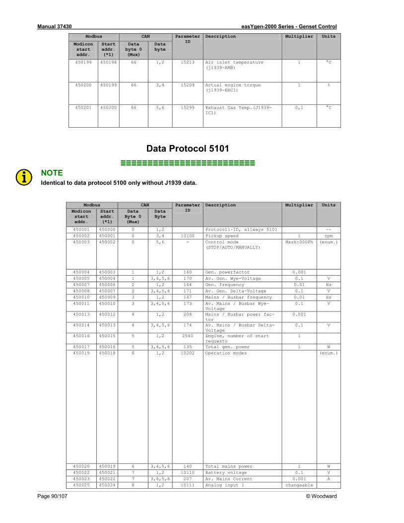
Manual 37430 easYgen-2000 Series - Genset Control
Page 90/107 © Woodward
Modbus CAN Parameter ID
Description Multiplier Units
Modicon start addr.
Start addr. (*1)
Data byte 0 (Mux)
Data byte
450199 450198 66 1,2 15213 Air inlet temperature (j1939-AMB)
1 °C
450200 450199 66 3,4 15209 Actual engine torque (j1939-EEC1)
1 %
450201 450200 66 5,6 15299 Exhaust Gas Temp.(J1939-IC1)
0,1 °C
Data Protocol 5101 ≡≡≡≡≡≡≡≡≡≡≡≡≡≡≡≡≡≡≡≡≡≡≡≡≡
NOTE Identical to data protocol 5100 only without J1939 data.
Modbus CAN Parameter ID
Description Multiplier Units Modicon start addr.
Start addr. (*1)
Data Byte 0 (Mux)
Data Byte
450001 450000 0 1,2 Protocoll-ID, allways 5101 -- 450002 450001 0 3,4 10100 Pickup speed 1 rpm 450003 450002 0 5,6 - Control mode
(STOP/AUTO/MANUALLY) Mask:000Fh (enum.)
450004 450003 1 1,2 160 Gen. powerfactor 0.001 450005 450004 1 3,4,5,6 170 Av. Gen. Wye-Voltage 0.1 V 450007 450006 2 1,2 144 Gen. frequency 0.01 Hz 450008 450007 2 3,4,5,6 171 Av. Gen. Delta-Voltage 0.1 V 450010 450009 3 1,2 147 Mains / Busbar frequency 0.01 Hz 450011 450010 3 3,4,5,6 173 Av. Mains / Busbar Wye-
Voltage 0.1 V
450013 450012 4 1,2 208 Mains / Busbar power fac-tor
0.001
450014 450013 4 3,4,5,6 174 Av. Mains / Busbar Delta-Voltage
0.1 V
450016 450015 5 1,2 2540 Engine, number of start requests
1
450017 450016 5 3,4,5,6 135 Total gen. power 1 W 450019 450018 6 1,2 10202 Operation modes (enum.)
450020 450019 6 3,4,5,6 140 Total mains power 1 W 450022 450021 7 1,2 10110 Battery voltage 0.1 V 450023 450022 7 3,4,5,6 207 Av. Mains Current 0.001 A 450025 450024 8 1,2 10111 Analog input 1 changeable
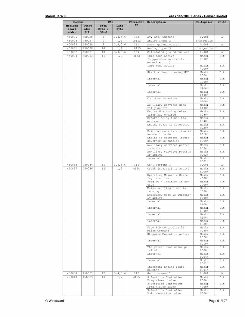
Manual 37430 easYgen-2000 Series - Genset Control
© Woodward Page 91/107
Modbus CAN Parameter ID
Description Multiplier Units Modicon start addr.
Start addr. (*1)
Data Byte 0 (Mux)
Data Byte
450026 450025 8 3,4,5,6 185 Av. Gen. Current 0.001 A 450028 450027 9 1,2 10112 Analog input 2 changeable 450029 450028 9 3,4,5,6 161 Meas. ground current 0.001 A 450031 450030 10 1,2 10115 Analog input 3 changeable 450032 450031 10 3,4,5,6 159 Calculated ground current 0.001 A 450034 450033 11 1,2 4153 Idle mode active
(suppresses undervolt, underfreq,...)
Mask: 8000h
Bit
Idle mode active Mask: 4000h
Bit
Start without closing GCB Mask: 2000h
Bit
internal Mask: 1000h
Bit
internal Mask: 0800h
Bit
internal Mask: 0400h
Bit
Cooldown is active Mask: 0200h
Bit
Auxiliary services gene-rally active
Mask: 0100h
Bit
Engine Monitoring delay timer has expired
Mask: 0080h
Bit
Breaker delay timer has expired
Mask: 0040h
Bit
Engine start is requested Mask: 0020h
Bit
Critical mode is active in automatic mode
Mask: 0010h
Bit
Engine is released (speed governor is enabled)
Mask: 0008h
Bit
Auxiliary services prerun is active
Mask: 0004h
Bit
Auxiliary services postrun is active
Mask: 0002h
Bit
internal Mask: 0001h
Bit
450035 450034 11 3,4,5,6 111 Gen. current 1 0.001 A 450037 450036 12 1,2 4154 Crank (Starter) is active Mask:
8000h Bit
Operating Magnet / Gasre-lay is active
Mask: 4000h
Bit
Preglow / Ignition is ac-tive
Mask: 2000h
Bit
Mains settling timer is running
Mask: 1000h
Bit
Emergency mode is current-ly active
Mask: 0800h
Bit
internal Mask: 0400h
Bit
internal Mask: 0200h
Bit
internal Mask: 0100h
Bit
internal Mask: 0080h
Bit
Free PID Controller 2: Raise Command
Mask: 0040h
Bit
Stopping Magnet is active Mask: 0020h
Bit
internal Mask: 0010h
Bit
The genset runs mains pa-rallel
Mask: 0008h
Bit
internal Mask: 0004h
Bit
internal Mask: 0002h
Bit
Increment Engine Start Counter
Mask: 0001h
Bit
450038 450037 12 3,4,5,6 112 Gen. current 2 0.001 A 450040 450039 13 1,2 4155 3-Position Controller
Freq./Power raise Mask: 8000h
Bit
3-Position Controller Freq./Power lower
Mask: 4000h
Bit
3-Position Controller Volt./ReactPow raise
Mask: 2000h
Bit
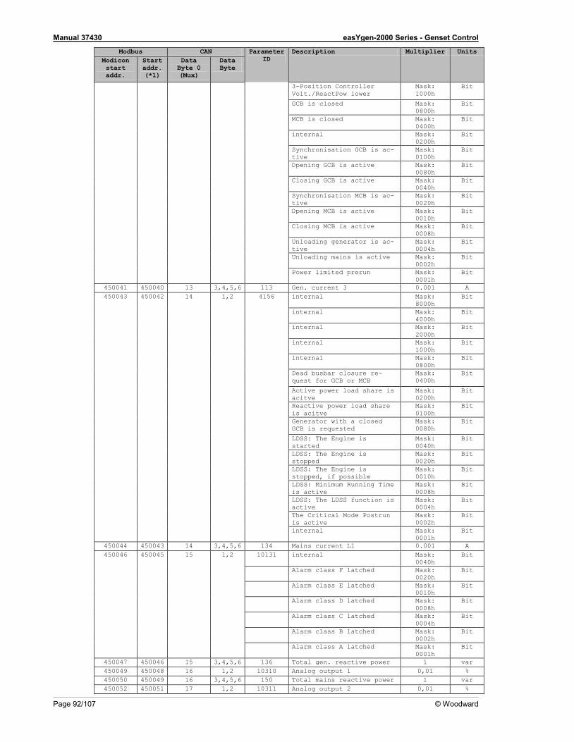
Manual 37430 easYgen-2000 Series - Genset Control
Page 92/107 © Woodward
Modbus CAN Parameter ID
Description Multiplier Units Modicon start addr.
Start addr. (*1)
Data Byte 0 (Mux)
Data Byte
3-Position Controller Volt./ReactPow lower
Mask: 1000h
Bit
GCB is closed Mask: 0800h
Bit
MCB is closed Mask: 0400h
Bit
internal Mask: 0200h
Bit
Synchronisation GCB is ac-tive
Mask: 0100h
Bit
Opening GCB is active Mask: 0080h
Bit
Closing GCB is active Mask: 0040h
Bit
Synchronisation MCB is ac-tive
Mask: 0020h
Bit
Opening MCB is active Mask: 0010h
Bit
Closing MCB is active Mask: 0008h
Bit
Unloading generator is ac-tive
Mask: 0004h
Bit
Unloading mains is active Mask: 0002h
Bit
Power limited prerun Mask: 0001h
Bit
450041 450040 13 3,4,5,6 113 Gen. current 3 0.001 A 450043 450042 14 1,2 4156 internal Mask:
8000h Bit
internal Mask: 4000h
Bit
internal Mask: 2000h
Bit
internal Mask: 1000h
Bit
internal Mask: 0800h
Bit
Dead busbar closure re-quest for GCB or MCB
Mask: 0400h
Bit
Active power load share is acitve
Mask: 0200h
Bit
Reactive power load share is acitve
Mask: 0100h
Bit
Generator with a closed GCB is requested
Mask: 0080h
Bit
LDSS: The Engine is started
Mask: 0040h
Bit
LDSS: The Engine is stopped
Mask: 0020h
Bit
LDSS: The Engine is stopped, if possible
Mask: 0010h
Bit
LDSS: Minimum Running Time is active
Mask: 0008h
Bit
LDSS: The LDSS function is active
Mask: 0004h
Bit
The Critical Mode Postrun is active
Mask: 0002h
Bit
internal Mask: 0001h
Bit
450044 450043 14 3,4,5,6 134 Mains current L1 0.001 A 450046 450045 15 1,2 10131 internal Mask:
0040h Bit
Alarm class F latched Mask: 0020h
Bit
Alarm class E latched Mask: 0010h
Bit
Alarm class D latched Mask: 0008h
Bit
Alarm class C latched Mask: 0004h
Bit
Alarm class B latched Mask: 0002h
Bit
Alarm class A latched Mask: 0001h
Bit
450047 450046 15 3,4,5,6 136 Total gen. reactive power 1 var 450049 450048 16 1,2 10310 Analog output 1 0,01 % 450050 450049 16 3,4,5,6 150 Total mains reactive power 1 var 450052 450051 17 1,2 10311 Analog output 2 0,01 %
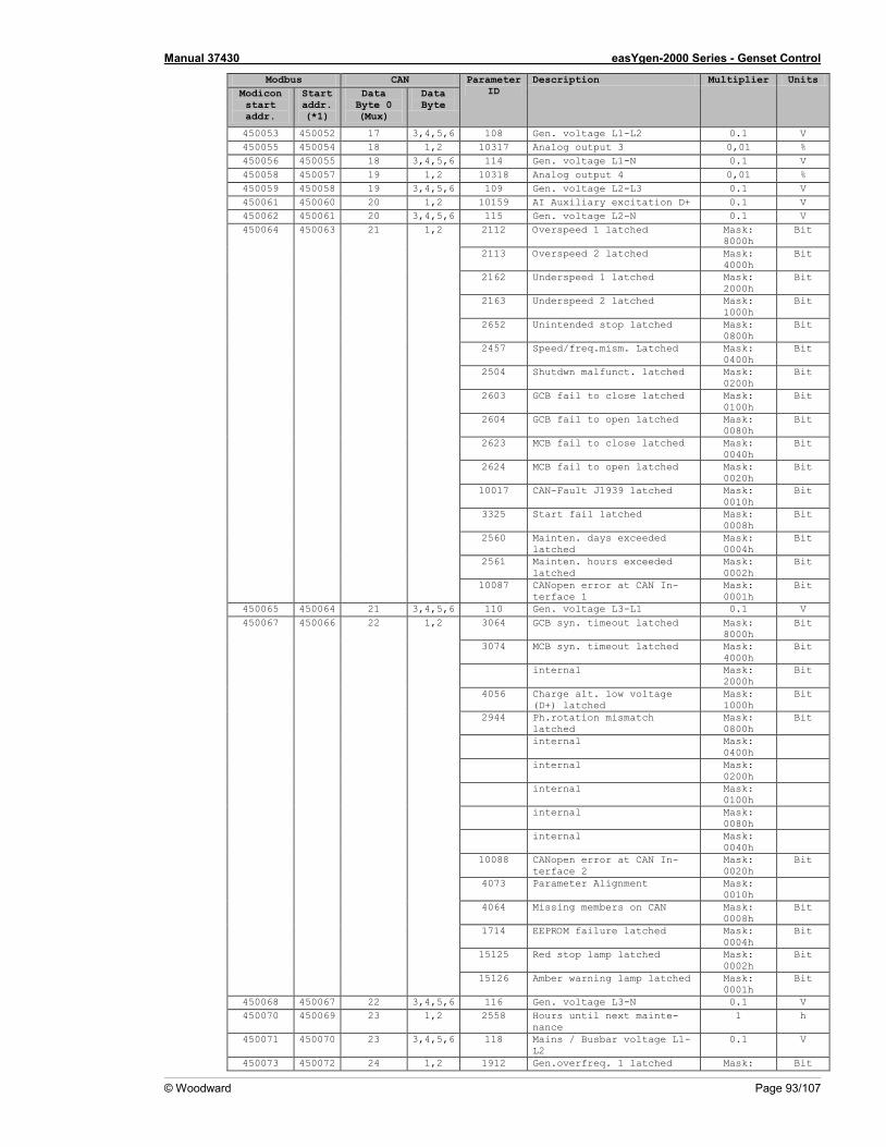
Manual 37430 easYgen-2000 Series - Genset Control
© Woodward Page 93/107
Modbus CAN Parameter ID
Description Multiplier Units Modicon start addr.
Start addr. (*1)
Data Byte 0 (Mux)
Data Byte
450053 450052 17 3,4,5,6 108 Gen. voltage L1-L2 0.1 V 450055 450054 18 1,2 10317 Analog output 3 0,01 % 450056 450055 18 3,4,5,6 114 Gen. voltage L1-N 0.1 V 450058 450057 19 1,2 10318 Analog output 4 0,01 % 450059 450058 19 3,4,5,6 109 Gen. voltage L2-L3 0.1 V 450061 450060 20 1,2 10159 AI Auxiliary excitation D+ 0.1 V 450062 450061 20 3,4,5,6 115 Gen. voltage L2-N 0.1 V 450064 450063 21 1,2 2112 Overspeed 1 latched Mask:
8000h Bit
2113 Overspeed 2 latched Mask: 4000h
Bit
2162 Underspeed 1 latched Mask: 2000h
Bit
2163 Underspeed 2 latched Mask: 1000h
Bit
2652 Unintended stop latched Mask: 0800h
Bit
2457 Speed/freq.mism. Latched Mask: 0400h
Bit
2504 Shutdwn malfunct. latched Mask: 0200h
Bit
2603 GCB fail to close latched Mask: 0100h
Bit
2604 GCB fail to open latched Mask: 0080h
Bit
2623 MCB fail to close latched Mask: 0040h
Bit
2624 MCB fail to open latched Mask: 0020h
Bit
10017 CAN-Fault J1939 latched Mask: 0010h
Bit
3325 Start fail latched Mask: 0008h
Bit
2560 Mainten. days exceeded latched
Mask: 0004h
Bit
2561 Mainten. hours exceeded latched
Mask: 0002h
Bit
10087 CANopen error at CAN In-terface 1
Mask: 0001h
Bit
450065 450064 21 3,4,5,6 110 Gen. voltage L3-L1 0.1 V 450067 450066 22 1,2 3064 GCB syn. timeout latched Mask:
8000h Bit
3074 MCB syn. timeout latched Mask: 4000h
Bit
internal Mask: 2000h
Bit
4056 Charge alt. low voltage (D+) latched
Mask: 1000h
Bit
2944 Ph.rotation mismatch latched
Mask: 0800h
Bit
internal Mask: 0400h
internal Mask: 0200h
internal Mask: 0100h
internal Mask: 0080h
internal Mask: 0040h
10088 CANopen error at CAN In-terface 2
Mask: 0020h
Bit
4073 Parameter Alignment Mask: 0010h
4064 Missing members on CAN Mask: 0008h
Bit
1714 EEPROM failure latched Mask: 0004h
Bit
15125 Red stop lamp latched Mask: 0002h
Bit
15126 Amber warning lamp latched Mask: 0001h
Bit
450068 450067 22 3,4,5,6 116 Gen. voltage L3-N 0.1 V 450070 450069 23 1,2 2558 Hours until next mainte-
nance 1 h
450071 450070 23 3,4,5,6 118 Mains / Busbar voltage L1-L2
0.1 V
450073 450072 24 1,2 1912 Gen.overfreq. 1 latched Mask: Bit
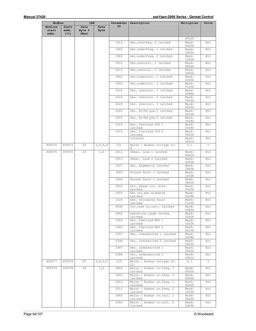
Manual 37430 easYgen-2000 Series - Genset Control
Page 94/107 © Woodward
Modbus CAN Parameter ID
Description Multiplier Units Modicon start addr.
Start addr. (*1)
Data Byte 0 (Mux)
Data Byte
8000h 1913 Gen.overfreq. 2 latched Mask:
4000h Bit
1962 Gen.underfreq. 1 latched Mask: 2000h
Bit
1963 Gen.underfreq. 2 latched Mask: 1000h
Bit
2012 Gen.overvolt. 1 latched Mask: 0800h
Bit
2013 Gen.overvolt. 2 latched Mask: 0400h
Bit
2062 Gen.undervolt. 1 latched Mask: 0200h
Bit
2063 Gen.undervolt. 2 latched Mask: 0100h
Bit
2218 Gen. overcurr. 1 latched Mask: 0080h
Bit
2219 Gen. overcurr. 2 latched Mask: 0040h
Bit
2220 Gen. overcurr. 3 latched Mask: 0020h
Bit
2262 Gen. Rv/Rd pow.1 latched Mask: 0010h
Bit
2263 Gen. Rv/Rd pow.2 latched Mask: 0008h
Bit
2314 Gen. Overload IOP 1 latched
Mask: 0004h
Bit
2315 Gen. Overload IOP 2 latched
Mask: 0002h
Bit
internal Mask: 0001h
Bit
450074 450073 24 3,4,5,6 121 Mains / Busbar voltage L1-N
0.1 V
450076 450075 25 1,2 2412 Unbal. load 1 latched Mask: 8000h
Bit
2413 Unbal. load 2 latched Mask: 4000h
Bit
3907 Gen. Asymmetry latched Mask: 2000h
Bit
3263 Ground fault 1 latched Mask: 1000h
Bit
3264 Ground fault 2 latched Mask: 0800h
Bit
3955 Gen. phase rot. misw. Latched
Mask: 0400h
Bit
2924 Gen act.pwr mismatch Latched
Mask: 0200h
Bit
3124 Gen. unloading fault Latched
Mask: 0100h
Bit
4038 Inv.time ov.curr. Latched Mask: 0080h
Bit
2664 Operating range failed, latched
Mask: 0040h
Bit
2362 Gen. Overload MOP 1 latched
Mask: 0020h
Bit
2363 Gen. Overload MOP 2 latched
Mask: 0010h
Bit
2337 Gen. overexcited 1 latched Mask: 0008h
Bit
2338 Gen. overexcited 2 latched Mask: 0004h
Bit
2387 Gen. underexcited 1 latched
Mask: 0002h
Bit
2388 Gen. underexcited 2 latched
Mask: 0001h
Bit
450077 450076 25 3,4,5,6 119 Mains / Busbar voltage L2-L3
0.1 V
450079 450078 26 1,2 2862 Mains / Busbar ov.freq. 1 latched
Mask: 8000h
Bit
2863 Mains / Busbar ov.freq. 2 latched
Mask: 4000h
Bit
2912 Mains / Busbar un.freq. 1 latched
Mask: 2000h
Bit
2913 Mains / Busbar un.freq. 2 latched
Mask: 1000h
Bit
2962 Mains / Busbar ov.volt. 1 latched
Mask: 0800h
Bit
2963 Mains / Busbar ov.volt. 2 latched
Mask: 0400h
Bit
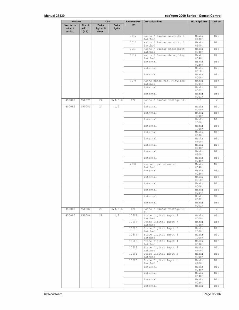
Manual 37430 easYgen-2000 Series - Genset Control
© Woodward Page 95/107
Modbus CAN Parameter ID
Description Multiplier Units Modicon start addr.
Start addr. (*1)
Data Byte 0 (Mux)
Data Byte
3012 Mains / Busbar un.volt. 1 latched
Mask: 0200h
Bit
3013 Mains / Busbar un.volt. 2 latched
Mask: 0100h
Bit
3057 Mains / Busbar phaseshift latched
Mask: 0080h
Bit
3114 Mains / Busbar decoupling latched
Mask: 0040h
Bit
internal Mask: 0020h
Bit
internal Mask: 0010h
Bit
internal Mask: 0008h
Bit
3975 Mains phase rot. Miswired latched
Mask: 0004h
Bit
internal Mask: 0002h
Bit
internal Mask: 0001h
Bit
450080 450079 26 3,4,5,6 122 Mains / Busbar voltage L2-N
0.1 V
450082 450081 27 1,2 internal Mask: 8000h
Bit
internal Mask: 4000h
Bit
internal Mask: 2000h
Bit
internal Mask: 1000h
Bit
internal Mask: 0800h
Bit
internal Mask: 0400h
Bit
internal Mask: 0200h
Bit
internal Mask: 0100h
Bit
internal Mask: 0080h
Bit
2934 Mns act.pwr mismatch latched
Mask: 0040h
Bit
internal Mask: 0020h
Bit
internal Mask: 0010h
Bit
internal Mask: 0008h
Bit
internal Mask: 0004h
Bit
internal Mask: 0002h
Bit
internal Mask: 0001h
Bit
450083 450082 27 3,4,5,6 120 Mains / Busbar voltage L3-L1
0.1 V
450085 450084 28 1,2 10608 State Digital Input 8 latched
Mask: 8000h
Bit
10607 State Digital Input 7 latched
Mask: 4000h
Bit
10605 State Digital Input 6 latched
Mask: 2000h
Bit
10604 State Digital Input 5 latched
Mask: 1000h
Bit
10603 State Digital Input 4 latched
Mask: 0800h
Bit
10602 State Digital Input 3 latched
Mask: 0400h
Bit
10601 State Digital Input 2 latched
Mask: 0200h
Bit
10600 State Digital Input 1 latched
Mask: 0100h
Bit
internal Mask: 0080h
Bit
internal Mask: 0040h
Bit
internal Mask: 0020h
Bit
internal Mask: Bit
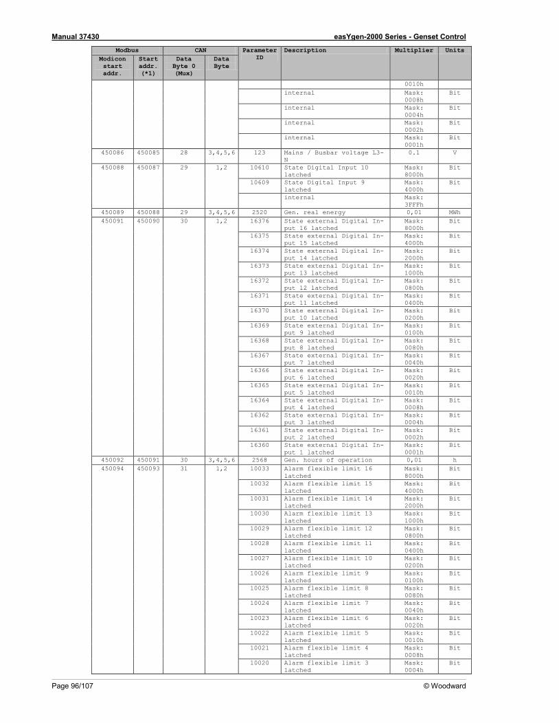
Manual 37430 easYgen-2000 Series - Genset Control
Page 96/107 © Woodward
Modbus CAN Parameter ID
Description Multiplier Units Modicon start addr.
Start addr. (*1)
Data Byte 0 (Mux)
Data Byte
0010h internal Mask:
0008h Bit
internal Mask: 0004h
Bit
internal Mask: 0002h
Bit
internal Mask: 0001h
Bit
450086 450085 28 3,4,5,6 123 Mains / Busbar voltage L3-N
0.1 V
450088 450087 29 1,2 10610 State Digital Input 10 latched
Mask: 8000h
Bit
10609 State Digital Input 9 latched
Mask: 4000h
Bit
internal Mask: 3FFFh
450089 450088 29 3,4,5,6 2520 Gen. real energy 0,01 MWh 450091 450090 30 1,2 16376 State external Digital In-
put 16 latched Mask: 8000h
Bit
16375 State external Digital In-put 15 latched
Mask: 4000h
Bit
16374 State external Digital In-put 14 latched
Mask: 2000h
Bit
16373 State external Digital In-put 13 latched
Mask: 1000h
Bit
16372 State external Digital In-put 12 latched
Mask: 0800h
Bit
16371 State external Digital In-put 11 latched
Mask: 0400h
Bit
16370 State external Digital In-put 10 latched
Mask: 0200h
Bit
16369 State external Digital In-put 9 latched
Mask: 0100h
Bit
16368 State external Digital In-put 8 latched
Mask: 0080h
Bit
16367 State external Digital In-put 7 latched
Mask: 0040h
Bit
16366 State external Digital In-put 6 latched
Mask: 0020h
Bit
16365 State external Digital In-put 5 latched
Mask: 0010h
Bit
16364 State external Digital In-put 4 latched
Mask: 0008h
Bit
16362 State external Digital In-put 3 latched
Mask: 0004h
Bit
16361 State external Digital In-put 2 latched
Mask: 0002h
Bit
16360 State external Digital In-put 1 latched
Mask: 0001h
Bit
450092 450091 30 3,4,5,6 2568 Gen. hours of operation 0,01 h 450094 450093 31 1,2 10033 Alarm flexible limit 16
latched Mask: 8000h
Bit
10032 Alarm flexible limit 15 latched
Mask: 4000h
Bit
10031 Alarm flexible limit 14 latched
Mask: 2000h
Bit
10030 Alarm flexible limit 13 latched
Mask: 1000h
Bit
10029 Alarm flexible limit 12 latched
Mask: 0800h
Bit
10028 Alarm flexible limit 11 latched
Mask: 0400h
Bit
10027 Alarm flexible limit 10 latched
Mask: 0200h
Bit
10026 Alarm flexible limit 9 latched
Mask: 0100h
Bit
10025 Alarm flexible limit 8 latched
Mask: 0080h
Bit
10024 Alarm flexible limit 7 latched
Mask: 0040h
Bit
10023 Alarm flexible limit 6 latched
Mask: 0020h
Bit
10022 Alarm flexible limit 5 latched
Mask: 0010h
Bit
10021 Alarm flexible limit 4 latched
Mask: 0008h
Bit
10020 Alarm flexible limit 3 latched
Mask: 0004h
Bit
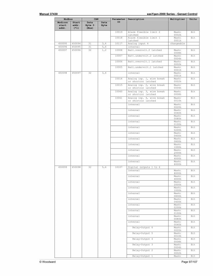
Manual 37430 easYgen-2000 Series - Genset Control
© Woodward Page 97/107
Modbus CAN Parameter ID
Description Multiplier Units Modicon start addr.
Start addr. (*1)
Data Byte 0 (Mux)
Data Byte
10019 Alarm flexible limit 2 latched
Mask: 0002h
Bit
10018 Alarm flexible limit 1 latched
Mask: 0001h
Bit
450095 450094 31 3,4 10117 Analog input 4 changeable 450096 450095 31 5,6 internal 450097 450096 32 1,2 10008 Batt.overvolt.2 latched Mask:
0008h Bit
10007 Batt.undervolt.2 latched Mask: 0004h
Bit
10006 Batt.overvolt.1 latched Mask: 0002h
Bit
10005 Batt.undervolt.1 latched Mask: 0001h
Bit
450098 450097 32 3,4 internal Mask: 0001h
Bit
10014 Analog inp. 1, wire break or shortcut latched
Mask: 0002h
Bit
10015 Analog inp. 2, wire break or shortcut latched
Mask: 0004h
Bit
10060 Analog inp. 3, wire break or shortcut latched
Mask: 0008h
Bit
10061 Analog inp. 4, wire break or shortcut latched
Mask: 0010h
Bit
internal Mask: 0020h
Bit
internal Mask: 0040h
Bit
internal Mask: 0080h
Bit
internal Mask: 0100h
Bit
internal Mask: 0200h
Bit
internal Mask: 0400h
Bit
internal Mask: 0800h
Bit
internal Mask: 1000h
Bit
internal Mask: 2000h
Bit
internal Mask: 4000h
Bit
internal Mask: 8000h
Bit
450099 450098 32 5,6 10107 Digital outputs 1 to 6 internal Mask:
8000h Bit
internal Mask: 4000h
Bit
internal Mask: 2000h
Bit
internal Mask: 1000h
Bit
internal Mask: 0800h
Bit
internal Mask: 0400h
Bit
internal Mask: 0200h
Bit
internal Mask: 0100h
Bit
internal Mask: 0080h
Bit
internal Mask: 0040h
Bit
Relay-Output 6 Mask: 0020h
Bit
Relay-Output 5 Mask: 0010h
Bit
Relay-Output 4 Mask: 0008h
Bit
Relay-Output 3 Mask: 0004h
Bit
Relay-Output 2 Mask: 0002h
Bit
Relay-Output 1 Mask: Bit
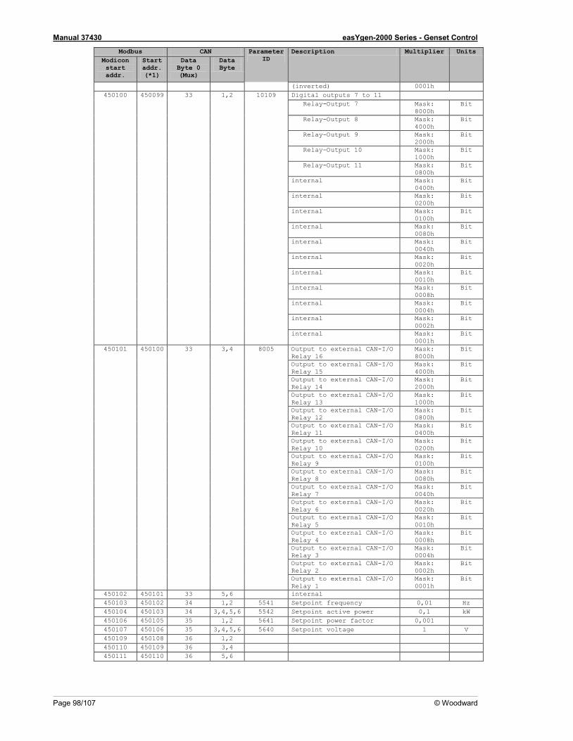
Manual 37430 easYgen-2000 Series - Genset Control
Page 98/107 © Woodward
Modbus CAN Parameter ID
Description Multiplier Units Modicon start addr.
Start addr. (*1)
Data Byte 0 (Mux)
Data Byte
(inverted) 0001h 450100 450099 33 1,2 10109 Digital outputs 7 to 11
Relay-Output 7 Mask: 8000h
Bit
Relay-Output 8 Mask: 4000h
Bit
Relay-Output 9 Mask: 2000h
Bit
Relay-Output 10 Mask: 1000h
Bit
Relay-Output 11 Mask: 0800h
Bit
internal Mask: 0400h
Bit
internal Mask: 0200h
Bit
internal Mask: 0100h
Bit
internal Mask: 0080h
Bit
internal Mask: 0040h
Bit
internal Mask: 0020h
Bit
internal Mask: 0010h
Bit
internal Mask: 0008h
Bit
internal Mask: 0004h
Bit
internal Mask: 0002h
Bit
internal Mask: 0001h
Bit
450101 450100 33 3,4 8005 Output to external CAN-I/O Relay 16
Mask: 8000h
Bit
Output to external CAN-I/O Relay 15
Mask: 4000h
Bit
Output to external CAN-I/O Relay 14
Mask: 2000h
Bit
Output to external CAN-I/O Relay 13
Mask: 1000h
Bit
Output to external CAN-I/O Relay 12
Mask: 0800h
Bit
Output to external CAN-I/O Relay 11
Mask: 0400h
Bit
Output to external CAN-I/O Relay 10
Mask: 0200h
Bit
Output to external CAN-I/O Relay 9
Mask: 0100h
Bit
Output to external CAN-I/O Relay 8
Mask: 0080h
Bit
Output to external CAN-I/O Relay 7
Mask: 0040h
Bit
Output to external CAN-I/O Relay 6
Mask: 0020h
Bit
Output to external CAN-I/O Relay 5
Mask: 0010h
Bit
Output to external CAN-I/O Relay 4
Mask: 0008h
Bit
Output to external CAN-I/O Relay 3
Mask: 0004h
Bit
Output to external CAN-I/O Relay 2
Mask: 0002h
Bit
Output to external CAN-I/O Relay 1
Mask: 0001h
Bit
450102 450101 33 5,6 internal 450103 450102 34 1,2 5541 Setpoint frequency 0,01 Hz 450104 450103 34 3,4,5,6 5542 Setpoint active power 0,1 kW 450106 450105 35 1,2 5641 Setpoint power factor 0,001 450107 450106 35 3,4,5,6 5640 Setpoint voltage 1 V 450109 450108 36 1,2 450110 450109 36 3,4 450111 450110 36 5,6
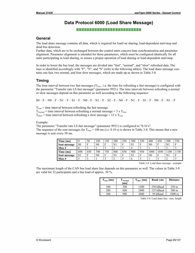
Manual 37430 easYgen-2000 Series - Genset Control
© Woodward Page 99/107
Data Protocol 6000 (Load Share Message) ≡≡≡≡≡≡≡≡≡≡≡≡≡≡≡≡≡≡≡≡≡≡≡≡≡
General The load share message contains all data, which is required for load/var sharing, load-dependent start/stop and dead bus detection. Further data, which are to be exchanged between the control units concern time synchronization and parameter alignment. Parameter alignment is intended for those parameters, which must be configured identically for all units participating in load sharing, to ensure a proper operation of load sharing or load-dependent start/stop. In order to lower the bus load, the messages are divided into "fast", "normal", and "slow" refreshed data. The mux is identified accordingly with "F", "N", and "S" (refer to the following tables). The load share message con-tains one fast, two normal, and four slow messages, which are made up as shown in Table 3-8.
Timing The time interval between two fast messages (TFast , i.e. the time for refreshing a fast message) is configured with the parameter "Transfer rate LS fast message" (parameter 9921). The time intervals between refreshing a normal or slow messages depend on this parameter as well according to the following sequence: S0 – F – N0 – F – N1 – F – S1 – F – N0 – F – N1 – F – S2 – F – N0 – F – N1 – F – S3 – F – N0 – F – N1 – F TFast = time interval between refreshing the fast message TNormal = time interval between refreshing a normal message = 3 x TFast TSlow = time interval between refreshing a slow message = 12 x TFast Example: The parameter "Transfer rate LS fast message" (parameter 9921) is configured to "0.10 s". The sequence of the sent messages for TFast = 100 ms (i.e. 0.10 s) is shown in Table 3-8. This means that a new message is sent every 50 ms.
Time [ms] 0 50 100 150 200 250 300 350 400 450 500 550 Sent message S0 F N0 F N1 F S1 F N0 F N1 F Mux # 0 3 1 3 2 3 4 3 1 3 2 3 Time [ms] 600 650 700 750 800 850 900 950 1000 1050 1100 1150 Sent message S2 F N0 F N1 F S3 F N0 F N1 F Mux # 5 3 1 3 2 3 6 3 1 3 2 3
Table 3-8: Load share message - example
The maximum length of the CAN bus load share line depends on this parameter as well. The values in Table 3-9 are valid for 32 participants and a bus load of approx. 30 %.
TFast [ms] TNormal [ms]
TSlow [ms] Baud rate Distance
100 300 1200 250 kBaud 250 m 200 600 2400 125 kBaud 500 m 300 900 3800 50 kBaud 1000 m
Table 3-9: Load share line - max. length
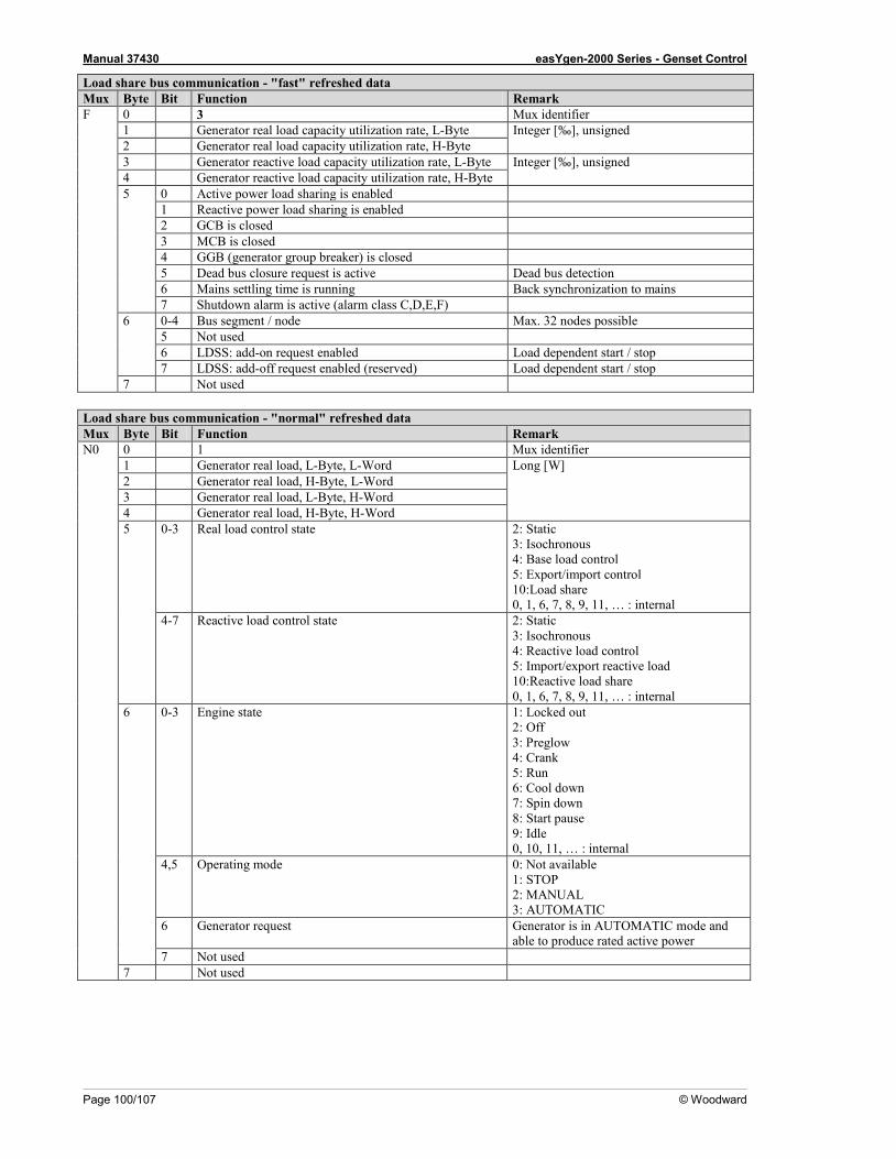
Manual 37430 easYgen-2000 Series - Genset Control
Page 100/107 © Woodward
Load share bus communication - "fast" refreshed data Mux Byte Bit Function Remark F 0 3 Mux identifier
1 Generator real load capacity utilization rate, L-Byte Integer [‰], unsigned 2 Generator real load capacity utilization rate, H-Byte 3 Generator reactive load capacity utilization rate, L-Byte Integer [‰], unsigned 4 Generator reactive load capacity utilization rate, H-Byte 5 0 Active power load sharing is enabled
1 Reactive power load sharing is enabled 2 GCB is closed 3 MCB is closed 4 GGB (generator group breaker) is closed 5 Dead bus closure request is active Dead bus detection 6 Mains settling time is running Back synchronization to mains 7 Shutdown alarm is active (alarm class C,D,E,F)
6 0-4 Bus segment / node Max. 32 nodes possible 5 Not used 6 LDSS: add-on request enabled Load dependent start / stop 7 LDSS: add-off request enabled (reserved) Load dependent start / stop
7 Not used Load share bus communication - "normal" refreshed data Mux Byte Bit Function Remark N0 0 1 Mux identifier
1 Generator real load, L-Byte, L-Word Long [W] 2 Generator real load, H-Byte, L-Word 3 Generator real load, L-Byte, H-Word 4 Generator real load, H-Byte, H-Word 5 0-3 Real load control state 2: Static
3: Isochronous 4: Base load control 5: Export/import control 10:Load share 0, 1, 6, 7, 8, 9, 11, … : internal
4-7 Reactive load control state 2: Static 3: Isochronous 4: Reactive load control 5: Import/export reactive load 10:Reactive load share 0, 1, 6, 7, 8, 9, 11, … : internal
6 0-3 Engine state 1: Locked out 2: Off 3: Preglow 4: Crank 5: Run 6: Cool down 7: Spin down 8: Start pause 9: Idle 0, 10, 11, … : internal
4,5 Operating mode 0: Not available 1: STOP 2: MANUAL 3: AUTOMATIC
6 Generator request Generator is in AUTOMATIC mode and able to produce rated active power
7 Not used 7 Not used
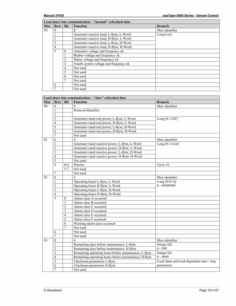
Manual 37430 easYgen-2000 Series - Genset Control
© Woodward Page 101/107
Load share bus communication - "normal" refreshed data Mux Byte Bit Function Remark N1 0 2 Mux identifier
1 Generator reactive load, L-Byte, L-Word Long [var] 2 Generator reactive load, H-Byte, L-Word 3 Generator reactive load, L-Byte, H-Word 4 Generator reactive load, H-Byte, H-Word 5 0 Generator voltage and frequency ok
1 Busbar voltage and frequency ok 2 Mains voltage and frequency ok 3 Fourth system voltage and frequency ok 4 Not used 5 Not used 6 Not used 7 Not used
6 Not used 7 Not used
Load share bus communication - "slow" refreshed data Mux Byte Bit Function Remark S0 0 0 Mux identifier
1 Protocol-Identifier 2 3 Generator rated real power, L-Byte, L-Word Long [0.1 kW] 4 Generator rated real power, H-Byte, L-Word 5 Generator rated real power, L-Byte, H-Word 6 Generator rated real power, H-Byte, H-Word 7 Not used
S1 0 4 Mux identifier 1 Generator rated reactive power, L-Byte, L-Word Long [0.1 kvar] 2 Generator rated reactive power, H-Byte, L-Word 3 Generator rated reactive power, L-Byte, H-Word 4 Generator rated reactive power, H-Byte, H-Word 5 Not used 6 0-4 Priority Up to 16
5-7 Not used 7 Not used
S2 0 5 Mux identifier 1 Operating hours L-Byte, L-Word Long [0.01 h]
0 - 99999999 2 Operating hours H-Byte, L-Word 3 Operating hours L-Byte, H-Word 4 Operating hours H-Byte, H-Word 5 0 Alarm class A occurred
1 Alarm class B occurred 2 Alarm class C occurred 3 Alarm class D occurred 4 Alarm class E occurred 5 Alarm class F occurred 6 Warning alarm class occurred 7 Not used
6 Not used 7 Not used
S3 0 6 Mux identifier 1 Remaining days before maintenance, L-Byte Integer [d]
0 - 999 2 Remaining days before maintenance, H-Byte 3 Remaining operating hours before maintenance, L-Byte Integer [h]
0 - 9999 4 Remaining operating hours before maintenance, H-Byte 5 Checksum parameters L-Byte Load share and load-dependent start / stop
parameters 6 Checksum parameters H-Byte 7 Not used
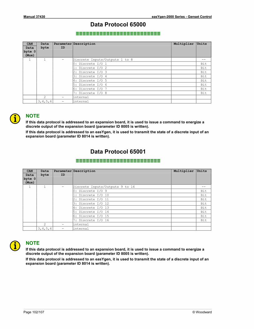
Manual 37430 easYgen-2000 Series - Genset Control
Page 102/107 © Woodward
Data Protocol 65000 ≡≡≡≡≡≡≡≡≡≡≡≡≡≡≡≡≡≡≡≡≡≡≡≡≡
CAN Data
byte Parameter
ID Description Multiplier Units
Data byte 0 (Mux) 1 1 - Discrete Inputs/Outputs 1 to 8 --
0: Discrete I/O 1 Bit 1: Discrete I/O 2 Bit 2: Discrete I/O 3 Bit 3: Discrete I/O 4 Bit 4: Discrete I/O 5 Bit 5: Discrete I/O 6 Bit 6: Discrete I/O 7 Bit 7: Discrete I/O 8 Bit
2 - internal 3,4,5,6 - internal
NOTE If this data protocol is addressed to an expansion board, it is used to issue a command to energize a discrete output of the expansion board (parameter ID 8005 is written). If this data protocol is addressed to an easYgen, it is used to transmit the state of a discrete input of an expansion board (parameter ID 8014 is written).
Data Protocol 65001 ≡≡≡≡≡≡≡≡≡≡≡≡≡≡≡≡≡≡≡≡≡≡≡≡≡
CAN Data
byte Parameter
ID Description Multiplier Units
Data byte 0 (Mux) 1 1 - Discrete Inputs/Outputs 9 to 16 --
0: Discrete I/O 9 Bit 1: Discrete I/O 10 Bit 2: Discrete I/O 11 Bit 3: Discrete I/O 12 Bit 4: Discrete I/O 13 Bit 5: Discrete I/O 14 Bit 6: Discrete I/O 15 Bit 7: Discrete I/O 16 Bit
2 - internal 3,4,5,6 - internal
NOTE If this data protocol is addressed to an expansion board, it is used to issue a command to energize a discrete output of the expansion board (parameter ID 8005 is written). If this data protocol is addressed to an easYgen, it is used to transmit the state of a discrete input of an expansion board (parameter ID 8014 is written).

Manual 37430 easYgen-2000 Series - Genset Control
© Woodward Page 103/107
Additional Data Protocol Parameters ≡≡≡≡≡≡≡≡≡≡≡≡≡≡≡≡≡≡≡≡≡≡≡≡≡
Remote Control Word 1 - Object 21F7h (Parameter ID 503) This object is required for remote control. The data type is UNSIGNED16. The internal parameter 503 of the easYgen must be set to react on the remote control instructions. This is per-formed by sending rising signals for the respective bits (refer to Figure 3-40 for the priority of start and stop sig-nals).
Para
met
er
no.
Obj
ect I
D Name
Unit Data type Note
503 21F7h Control word 1 Bit field unsigned16 Bit 15 Not used Bit 14 Not used Bit 13 Not used Bit 12 Not used Bit 11 Not used Bit 10 Not used Bit 9 Not used Bit 8 Not used Bit 7 Not used Bit 6 Not used Bit 5 Not used
Bit 4 Ext. Acknowledge (rising edge) Must be set twice to acknowledge
To acknowledge, a 0 must be written and then a 1
Bit 3 Must always be set to 0 Bit 2 Must always be set to 0
Bit 1 Stop bit (rising edge) To stop, a 0 must be written and then a 1
Bit 0 Start bit (rising edge) To start, a 0 must be written and then a 1
Table 3-10: Remote control telegram
Bit 0 Start bit With the rising edge of the bit, the easYgen activates the remote request command (LogicsManager input com-mand variable 04.13). The condition of the start command will be stored and may be used as command variable for the LogicsManager. Bit 1 Stop bit With the rising edge of the bit, the easYgen deactivates the remote request command (LogicsManager input command variable 04.13). The condition of the start command will be stored and may be used as command vari-able for the LogicsManager. Bit 4 "Reset alarms" This bit controls the LogicsManager input command variable 04.14. The remote acknowledge bit must be set and reset twice to acknowledge an alarm completely. The first rising edge disables the horn and the second rising edge resets the alarm.
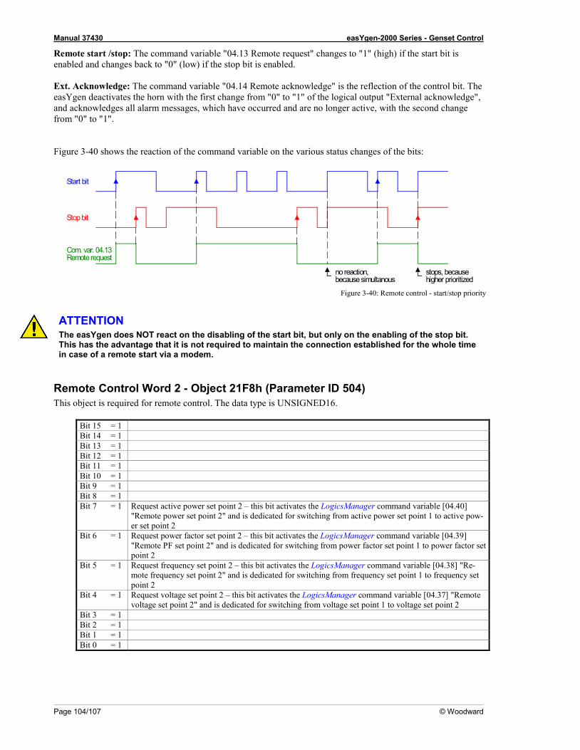
Manual 37430 easYgen-2000 Series - Genset Control
Page 104/107 © Woodward
Remote start /stop: The command variable "04.13 Remote request" changes to "1" (high) if the start bit is enabled and changes back to "0" (low) if the stop bit is enabled. Ext. Acknowledge: The command variable "04.14 Remote acknowledge" is the reflection of the control bit. The easYgen deactivates the horn with the first change from "0" to "1" of the logical output "External acknowledge", and acknowledges all alarm messages, which have occurred and are no longer active, with the second change from "0" to "1". Figure 3-40 shows the reaction of the command variable on the various status changes of the bits:
Figure 3-40: Remote control - start/stop priority
ATTENTION The easYgen does NOT react on the disabling of the start bit, but only on the enabling of the stop bit. This has the advantage that it is not required to maintain the connection established for the whole time in case of a remote start via a modem.
Remote Control Word 2 - Object 21F8h (Parameter ID 504) This object is required for remote control. The data type is UNSIGNED16.
Bit 15 = 1 Bit 14 = 1 Bit 13 = 1 Bit 12 = 1 Bit 11 = 1 Bit 10 = 1 Bit 9 = 1 Bit 8 = 1 Bit 7 = 1 Request active power set point 2 – this bit activates the LogicsManager command variable [04.40]
"Remote power set point 2" and is dedicated for switching from active power set point 1 to active pow-er set point 2
Bit 6 = 1 Request power factor set point 2 – this bit activates the LogicsManager command variable [04.39] "Remote PF set point 2" and is dedicated for switching from power factor set point 1 to power factor set point 2
Bit 5 = 1 Request frequency set point 2 – this bit activates the LogicsManager command variable [04.38] "Re-mote frequency set point 2" and is dedicated for switching from frequency set point 1 to frequency set point 2
Bit 4 = 1 Request voltage set point 2 – this bit activates the LogicsManager command variable [04.37] "Remote voltage set point 2" and is dedicated for switching from voltage set point 1 to voltage set point 2
Bit 3 = 1 Bit 2 = 1 Bit 1 = 1 Bit 0 = 1
stops, becausehigher prioritized
Start bit
Stop bit
Com. var. 04.13Remote request
no reaction,because simultanous

Manual 37430 easYgen-2000 Series - Genset Control
© Woodward Page 105/107
Remote Control Word 3 - Object 21F9h (Parameter ID 505) This object is required for remote control. These remote control bits can be used by a PLC to send control signals via SDO or PDO, which can then be used as command variables in the LogicsManager to control the easYgen. The data type is UNSIGNED16.
Bit 15 = 1 Remote control bit 16 (command variable 04.59) Bit 14 = 1 Remote control bit 15 (command variable 04.58) Bit 13 = 1 Remote control bit 14 (command variable 04.57) Bit 12 = 1 Remote control bit 13 (command variable 04.56) Bit 11 = 1 Remote control bit 12 (command variable 04.55) Bit 10 = 1 Remote control bit 11 (command variable 04.54) Bit 9 = 1 Remote control bit 10 (command variable 04.53) Bit 8 = 1 Remote control bit 9 (command variable 04.52) Bit 7 = 1 Remote control bit 8 (command variable 04.51) Bit 6 = 1 Remote control bit 7 (command variable 04.50) Bit 5 = 1 Remote control bit 6 (command variable 04.49) Bit 4 = 1 Remote control bit 5 (command variable 04.48) Bit 3 = 1 Remote control bit 4 (command variable 04.47) Bit 2 = 1 Remote control bit 3 (command variable 04.46) Bit 1 = 1 Remote control bit 2 (command variable 04.45) Bit 0 = 1 Remote control bit 1 (command variable 04.44)
Remote Active Power Set Point - Object 21FBh (Parameter ID 507) This value may be used as data source "[05.06] Interface pwr. setp." via the Analog Manager. No password is re-quired to write this value. This object is required to transmit the active power set point for active power control. The data type is INTEGER32. The value is scaled in [kW * 10]. Example: 100 kW = 1000 = 03E8h
Remote Power Factor Set Point - Object 21FCh (Parameter ID 508) This value may be used as data source "[05.12] Interface PF setp." via the Analog Manager. No password is re-quired to write this value. This object is required to transmit the power factor set point for power factor control. The data type is INTEGER16. The valid range for this value is [-710 to 1000 to 710]. Example: PF (cosphi) = c0.71 (capacitive) = -710 = FD3Ah PF (cosphi) = 1.00 = 1000 = 03E8h PF (cosphi) = i0.71 (inductive) = 710 = 02C6h
Remote Frequency Set Point - Object 21FDh (Parameter ID 509) This value may be used as data source "[05.03] Interface freq.setp." via the Analog Manager. No password is re-quired to write this value. This object is required to transmit the frequency set point for frequency control. The data type is UNSIGNED16. The value is scaled in [Hz * 100]. Example: 50.00 Hz = 5000 = 1388h
Remote Voltage Set Point - Object 21FEh (Parameter ID 510) This value may be used as data source "[05.09] Interface volt.setp." via the Analog Manager. No password is re-quired to write this value. This object is required to transmit the voltage set point for voltage control. The data type is UNSIGNED32. The value is scaled in [V]. Example: 400 V = 400 = 190h 10000 V = 10000 = 2710h
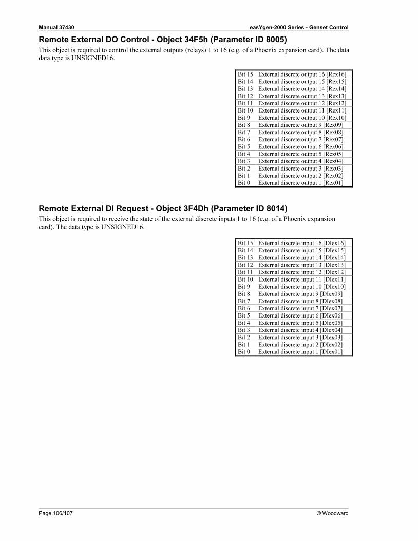
Manual 37430 easYgen-2000 Series - Genset Control
Page 106/107 © Woodward
Remote External DO Control - Object 34F5h (Parameter ID 8005) This object is required to control the external outputs (relays) 1 to 16 (e.g. of a Phoenix expansion card). The data data type is UNSIGNED16.
Bit 15 External discrete output 16 [Rex16] Bit 14 External discrete output 15 [Rex15] Bit 13 External discrete output 14 [Rex14] Bit 12 External discrete output 13 [Rex13] Bit 11 External discrete output 12 [Rex12] Bit 10 External discrete output 11 [Rex11] Bit 9 External discrete output 10 [Rex10] Bit 8 External discrete output 9 [Rex09] Bit 7 External discrete output 8 [Rex08] Bit 6 External discrete output 7 [Rex07] Bit 5 External discrete output 6 [Rex06] Bit 4 External discrete output 5 [Rex05] Bit 3 External discrete output 4 [Rex04] Bit 2 External discrete output 3 [Rex03] Bit 1 External discrete output 2 [Rex02] Bit 0 External discrete output 1 [Rex01]
Remote External DI Request - Object 3F4Dh (Parameter ID 8014) This object is required to receive the state of the external discrete inputs 1 to 16 (e.g. of a Phoenix expansion card). The data type is UNSIGNED16.
Bit 15 External discrete input 16 [DIex16] Bit 14 External discrete input 15 [DIex15] Bit 13 External discrete input 14 [DIex14] Bit 12 External discrete input 13 [DIex13] Bit 11 External discrete input 12 [DIex12] Bit 10 External discrete input 11 [DIex11] Bit 9 External discrete input 10 [DIex10] Bit 8 External discrete input 9 [DIex09] Bit 7 External discrete input 8 [DIex08] Bit 6 External discrete input 7 [DIex07] Bit 5 External discrete input 6 [DIex06] Bit 4 External discrete input 5 [DIex05] Bit 3 External discrete input 4 [DIex04] Bit 2 External discrete input 3 [DIex03] Bit 1 External discrete input 2 [DIex02] Bit 0 External discrete input 1 [DIex01]
We appreciate your comments about the content of our publications. Please send comments to: [email protected]
Please include the manual number from the front cover of this publication.
Woodward GmbH Handwerkstrasse 29 - 70565 Stuttgart - Germany
Phone +49 (0) 711-789 54-0 • Fax +49 (0) 711-789 54-100 [email protected]
Homepage
http://www.woodward.com/power
Woodward has company-owned plants, subsidiaries, and branches, as well as authorized distributors and other authorized service and sales facilities throughout the world.
Complete address/phone/fax/e-mail information
for all locations is available on our website (www.woodward.com).
2009/06/Stuttgart