Embed Size (px)
Citation preview

37390
Installation Software Version 2.1xxx
Manual 37390
easYgen-1000 Genset Control

Manual 37390 easYgen-1000 Series - Genset Control
Page 2/55 © Woodward
WARNING Read this entire manual and all other publications pertaining to the work to be performed before install-ing, operating, or servicing this equipment. Practice all plant and safety instructions and precautions. Failure to follow instructions can cause personal injury and/or property damage. The engine, turbine, or other type of prime mover should be equipped with an overspeed (overtempera-ture, or overpressure, where applicable) shutdown device(s), that operates totally independently of the prime mover control device(s) to protect against runaway or damage to the engine, turbine, or other type of prime mover with possible personal injury or loss of life should the mechanical-hydraulic gov-ernor(s) or electric control(s), the actuator(s), fuel control(s), the driving mechanism(s), the linkage(s), or the controlled device(s) fail. Any unauthorized modifications to or use of this equipment outside its specified mechanical, electrical, or other operating limits may cause personal injury and/or property damage, including damage to the equipment. Any such unauthorized modifications: (i) constitute "misuse" and/or "negligence" within the meaning of the product warranty thereby excluding warranty coverage for any resulting damage, and (ii) invalidate product certifications or listings.
CAUTION To prevent damage to a control system that uses an alternator or battery-charging device, make sure the charging device is turned off before disconnecting the battery from the system. Electronic controls contain static-sensitive parts. Observe the following precautions to prevent dam-age to these parts. • Discharge body static before handling the control (with power to the control turned off, contact a
grounded surface and maintain contact while handling the control). • Avoid all plastic, vinyl, and Styrofoam (except antistatic versions) around printed circuit boards. • Do not touch the components or conductors on a printed circuit board with your hands or with
conductive devices.
OUT-OF-DATE PUBLICATION This publication may have been revised or updated since this copy was produced. To verify that you have the latest revision, be sure to check the Woodward website: http://www.woodward.com/pubs/current.pdf The revision level is shown at the bottom of the front cover after the publication number. The latest version of most publications is available at: http://www.woodward.com/publications If your publication is not there, please contact your customer service representative to get the latest copy.
Important definitions
WARNING Indicates a potentially hazardous situation that, if not avoided, could result in death or serious injury.
CAUTION Indicates a potentially hazardous situation that, if not avoided, could result in damage to equipment.
NOTE Provides other helpful information that does not fall under the warning or caution categories.
Woodward reserves the right to update any portion of this publication at any time. Information provided by Woodward is believed to be correct and reliable. However, Woodward assumes no responsibility unless otherwise expressly undertaken.
© Woodward
All Rights Reserved.
Manual 37390 easYgen-1000 Series - Genset Control
© Woodward Page 3/55
Revision History
Rev. Date Editor Changes NEW 07-02-02 TP Release based on manual 37320B
Content
CHAPTER 1. GENERAL INFORMATION.........................................................................................7 CHAPTER 2. ELECTROSTATIC DISCHARGE AWARENESS.............................................................8 CHAPTER 3. MARINE USAGE .....................................................................................................9 Application...............................................................................................................................................9 Wiring ......................................................................................................................................................9 Measurement ..........................................................................................................................................9 CHAPTER 4. HOUSING.............................................................................................................10 Panel Cutout .........................................................................................................................................10 Dimensions ...........................................................................................................................................11 Side View ..............................................................................................................................................12 Installation .............................................................................................................................................13 CHAPTER 5. WIRING DIAGRAMS - OVERVIEW ...........................................................................14 Total Overview ......................................................................................................................................15 Application Mode {0} .............................................................................................................................18 Application Mode {1o} ...........................................................................................................................19 Application Mode {1oc} .........................................................................................................................20 Application Mode {2oc} .........................................................................................................................21 CHAPTER 6. CONNECTIONS.....................................................................................................22 Power Supply ........................................................................................................................................23 Voltage Measuring (FlexRange) ...........................................................................................................24
Voltage Measuring: Generator ...................................................................................................24 Voltage Measuring: Mains ..........................................................................................................28
Current Measuring ................................................................................................................................32 Generator....................................................................................................................................32 Mains Current ({2oc} Only) .........................................................................................................34 Ground Current ...........................................................................................................................35
Power Measuring ..................................................................................................................................36 Power Factor Definition.........................................................................................................................36 Pickup....................................................................................................................................................38 Discrete Inputs ......................................................................................................................................39
Discrete Inputs: Bipolar Signals..................................................................................................39 Discrete Inputs: Operation Logic ................................................................................................40
Relay Outputs (Control Outputs And LogicsManager) .........................................................................41 Analog Inputs (FlexIn) ...........................................................................................................................43
Wiring Two-Pole Sensors ...........................................................................................................43 Wiring Single-Pole Sensors ........................................................................................................44
Interfaces ..............................................................................................................................................45 Overview .....................................................................................................................................45 CAN Bus (FlexCAN) ...................................................................................................................46 DPC - Direct Configuration Cable...............................................................................................47
Manual 37390 easYgen-1000 Series - Genset Control
Page 4/55 © Woodward
CHAPTER 7. TECHNICAL DATA................................................................................................ 48 CHAPTER 8. ENVIRONMENTAL DATA ....................................................................................... 51 CHAPTER 9. ACCURACY ......................................................................................................... 52 CHAPTER 10. DECLARATION OF CONFORMITY ........................................................................ 53
Manual 37390 easYgen-1000 Series - Genset Control
© Woodward Page 5/55
Illustrations and Tables
Illustrations Figure 4-1: Housing - panel-board cutout ................................................................................................................................ 10 Figure 4-2: Housing - dimensions............................................................................................................................................ 11 Figure 4-3: Side view - without clamps ................................................................................................................................... 12 Figure 4-4: Side view - with clamps ........................................................................................................................................ 12 Figure 5-1: Wiring diagram - total overview ........................................................................................................................... 15 Figure 5-2: Wiring diagram - application mode {0} - base mode............................................................................................ 18 Figure 5-3: Wiring diagram - application mode {1o} - 1 CB mode......................................................................................... 19 Figure 5-4: Wiring diagram - application mode {1oc} - 1 CB mode....................................................................................... 20 Figure 5-5: Wiring diagram - application mode {2oc} - 2 CB mode....................................................................................... 21 Figure 6-1: Power supply......................................................................................................................................................... 23 Figure 6-2: Power supply - crank waveform at maximum load ............................................................................................... 23 Figure 6-3: Voltage measuring (FlexRange) - generator......................................................................................................... 24 Figure 6-4: Voltage measuring (FlexRange) -generator, 3ph 4w............................................................................................ 25 Figure 6-5: Voltage measuring (FlexRange) - generator, 3ph 3w........................................................................................... 26 Figure 6-6: Voltage measuring (FlexRange) - generator, 1ph 3w........................................................................................... 27 Figure 6-7: Voltage measuring (FlexRange) - generator, 1ph 2w........................................................................................... 27 Figure 6-8: Voltage measuring (FlexRange) - mains .............................................................................................................. 28 Figure 6-9: Voltage measuring (FlexRange) - mains, 3ph 4w ................................................................................................ 29 Figure 6-10: Voltage measuring (FlexRange) - mains, 3ph 3w .............................................................................................. 30 Figure 6-11: Voltage measuring (FlexRange) - mains, 1ph 3w .............................................................................................. 31 Figure 6-12: Voltage measuring (FlexRange) - mains, 1ph 2w .............................................................................................. 31 Figure 6-13: Current measuring - generator............................................................................................................................. 32 Figure 6-14: Current measuring - generator, L1 L2 L3............................................................................................................ 33 Figure 6-15: Current measuring - Generator, Phase Lx ........................................................................................................... 33 Figure 6-16: Current measuring - mains current ...................................................................................................................... 34 Figure 6-17: Current measuring - generator, Phase Lx ............................................................................................................ 34 Figure 6-18: Current measuring - ground current .................................................................................................................... 35 Figure 6-19: Power measuring - direction of power ................................................................................................................ 36 Figure 6-20: Pickup - principle overview ................................................................................................................................ 38 Figure 6-21: Pickup input ........................................................................................................................................................ 38 Figure 6-22: Minimal necessary input voltage depending on frequency ................................................................................. 38 Figure 6-23: Discrete inputs - alarm/control input - positive signal........................................................................................ 39 Figure 6-24: Discrete inputs - alarm/control input - negative signal....................................................................................... 39 Figure 6-25: Discrete inputs - alarm/control inputs - operation logic ...................................................................................... 40 Figure 6-26: Relay outputs....................................................................................................................................................... 41 Figure 6-27: Analog inputs (FlexIn) - wiring two-pole sensors .............................................................................................. 43 Figure 6-28: Analog inputs (FlexIn) - wiring single-pole sensors........................................................................................... 44 Figure 6-29: Analog inputs (FlexIn) - wiring single- and two-pole sensors............................................................................ 44 Figure 6-30: Interfaces - overview........................................................................................................................................... 45 Figure 6-31: Interfaces - CAN bus (FlexCAN)........................................................................................................................ 46 Figure 6-32: Interfaces - CAN bus - wiring of shielding ......................................................................................................... 46 Figure 6-33: Interfaces - CAN bus - termination ..................................................................................................................... 46
Manual 37390 easYgen-1000 Series - Genset Control
Page 6/55 © Woodward
Tables Table 1-1: Manual - overview.................................................................................................................................................... 7 Table 4-1: Housing - panel cutout ........................................................................................................................................... 10 Table 5-1: Terminal overview, part 1 ...................................................................................................................................... 16 Table 5-2: Terminal overview, part 2 ...................................................................................................................................... 17 Table 6-1: Conversion chart - wire size ................................................................................................................................... 22 Table 6-2: Power supply - terminal assignment....................................................................................................................... 23 Table 6-3: Voltage measuring (FlexRange) - terminal assignment - generator voltage.......................................................... 24 Table 6-4: Voltage measuring (FlexRange) - terminal assignment - generator, 3ph 4w.......................................................... 25 Table 6-5: Voltage measuring (FlexRange) - terminal assignment - generator, 3ph 3w.......................................................... 26 Table 6-6: Voltage measuring (FlexRange) - terminal assignment - generator, 1ph 3w.......................................................... 27 Table 6-7: Voltage measuring (FlexRange) - terminal assignment - generator, 1ph 2w.......................................................... 27 Table 6-8: Voltage measuring (FlexRange) - terminal assignment - mains voltage ............................................................... 28 Table 6-9: Voltage measuring (FlexRange) - terminal assignment - mains, 3ph 4w ............................................................... 29 Table 6-10: Voltage measuring (FlexRange) - terminal assignment - mains, 3ph 3w ............................................................. 30 Table 6-11: Voltage measuring (FlexRange) - terminal assignment - mains, 1ph 3w ............................................................. 31 Table 6-12: Voltage measuring (FlexRange) - terminal assignment - mains, 1ph 2w ............................................................. 31 Table 6-13: Current measuring - terminal assignment - generator current .............................................................................. 32 Table 6-14: Current measuring - terminal assignment - generator, L1 L2 L3 ......................................................................... 33 Table 6-15: Current measuring - terminal assignment - generator, Phase Lx .......................................................................... 33 Table 6-16: Current measuring - terminal assignment - mains current .................................................................................... 34 Table 6-17: current measuring - terminal assignment - generator, Phase Lx........................................................................... 34 Table 6-18: Current measuring - terminal assignment - ground current .................................................................................. 35 Table 6-19: Pickup - terminal assignment ............................................................................................................................... 38 Table 6-20: Discrete input - terminal assignment - alarm/control inputs................................................................................. 40 Table 6-21: Relay outputs - terminal assignment, part 1 ......................................................................................................... 41 Table 6-22: Relay outputs - terminal assignment, part 1 ......................................................................................................... 42 Table 6-23: Analog inputs (FlexIn) - terminal assignment - wiring two-pole sensors ............................................................ 43 Table 6-24: Analog inputs (FlexIn) - terminal assignment - wiring single-pole sensors ........................................................ 44 Table 6-25: Interfaces - connection overview.......................................................................................................................... 45 Table 6-26: Maximum CAN bus length................................................................................................................................... 47
Manual 37390 easYgen-1000 Series - Genset Control
© Woodward Page 7/55
Chapter 1. General Information
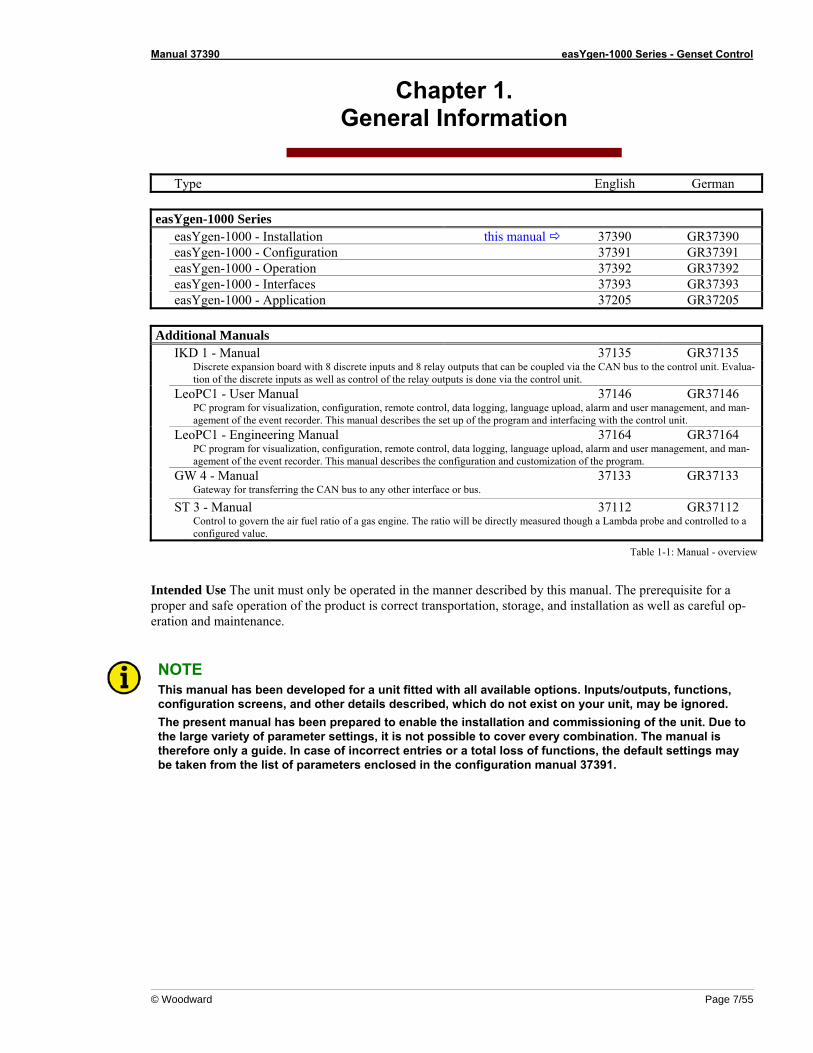
Type English German easYgen-1000 Series easYgen-1000 - Installation this manual 37390 GR37390 easYgen-1000 - Configuration 37391 GR37391 easYgen-1000 - Operation 37392 GR37392 easYgen-1000 - Interfaces 37393 GR37393 easYgen-1000 - Application 37205 GR37205 Additional Manuals IKD 1 - Manual 37135 GR37135 Discrete expansion board with 8 discrete inputs and 8 relay outputs that can be coupled via the CAN bus to the control unit. Evalua-
tion of the discrete inputs as well as control of the relay outputs is done via the control unit. LeoPC1 - User Manual 37146 GR37146 PC program for visualization, configuration, remote control, data logging, language upload, alarm and user management, and man-
agement of the event recorder. This manual describes the set up of the program and interfacing with the control unit. LeoPC1 - Engineering Manual 37164 GR37164 PC program for visualization, configuration, remote control, data logging, language upload, alarm and user management, and man-
agement of the event recorder. This manual describes the configuration and customization of the program. GW 4 - Manual 37133 GR37133 Gateway for transferring the CAN bus to any other interface or bus.
ST 3 - Manual 37112 GR37112 Control to govern the air fuel ratio of a gas engine. The ratio will be directly measured though a Lambda probe and controlled to a
configured value.
Table 1-1: Manual - overview
Intended Use The unit must only be operated in the manner described by this manual. The prerequisite for a proper and safe operation of the product is correct transportation, storage, and installation as well as careful op-eration and maintenance.
NOTE This manual has been developed for a unit fitted with all available options. Inputs/outputs, functions, configuration screens, and other details described, which do not exist on your unit, may be ignored. The present manual has been prepared to enable the installation and commissioning of the unit. Due to the large variety of parameter settings, it is not possible to cover every combination. The manual is therefore only a guide. In case of incorrect entries or a total loss of functions, the default settings may be taken from the list of parameters enclosed in the configuration manual 37391.

Manual 37390 easYgen-1000 Series - Genset Control
Page 8/55 © Woodward
Chapter 2. Electrostatic Discharge Awareness
All electronic equipment is static-sensitive, some components more than others. To protect these components from static damage, you must take special precautions to minimize or eliminate electrostatic discharges. Follow these precautions when working with or near the control. 1. Before doing maintenance on the electronic control, discharge the static electricity on your body to
ground by touching and holding a grounded metal object (pipes, cabinets, equipment, etc.). 2. Avoid the build-up of static electricity on your body by not wearing clothing made of synthetic materials.
Wear cotton or cotton-blend materials as much as possible because these do not store static electric char-ges as easily as synthetics.
3. Keep plastic, vinyl, and Styrofoam materials (such as plastic or Styrofoam cups, cigarette packages, cello-
phane wrappers, vinyl books or folders, plastic bottles, etc.) away from the control, modules, and work area as much as possible.
4. Opening the control cover may void the unit warranty.
Do not remove the printed circuit board (PCB) from the control cabinet unless absolutely necessary. If you must remove the PCB from the control cabinet, follow these precautions:
• Ensure that the device is completely voltage-free (all connectors have to be disconnected).
• Do not touch any part of the PCB except the edges.
• Do not touch the electrical conductors, connectors, or components with conductive devices or with
bare hands.
• When replacing a PCB, keep the new PCB in the plastic antistatic protective bag it comes in until you are ready to install it. Immediately after removing the old PCB from the control cabinet, place it in the antistatic protective bag.
CAUTION To prevent damage to electronic components caused by improper handling, read and observe the pre-cautions in Woodward manual 82715, Guide for Handling and Protection of Electronic Controls, Printed Circuit Boards, and Modules.

Manual 37390 easYgen-1000 Series - Genset Control
© Woodward Page 9/55
Chapter 3. Marine Usage
CAUTION The following notes are very important for marine usage of the easYgen genset control and have to be followed.
Application ≡≡≡≡≡≡≡≡≡≡≡≡≡≡≡≡≡≡≡≡≡≡≡≡≡
A DC/DC isolation converter must be used when the easYgen is used in an isolated power system application. The configuration interface input (RS-232) using the DPC converter is for maintenance and configuration only. Please refer to chapter DPC - Direct Configuration Cable on page 46 for information about the use of the DPC in normal operation. If the easYgen is to be used on bridge and deck zones, an EMI filter (i.e. TIMONTA FSS2-65-4/3) must be used for the power supply inputs.
Wiring ≡≡≡≡≡≡≡≡≡≡≡≡≡≡≡≡≡≡≡≡≡≡≡≡≡
Terminal 48 must be grounded at the control of the unit.
Measurement ≡≡≡≡≡≡≡≡≡≡≡≡≡≡≡≡≡≡≡≡≡≡≡≡≡
The easYgen will experience less than a 2% deviation in current measurements when exposed to electro-magnetic radiation.
Manual 37390 easYgen-1000 Series - Genset Control
Page 10/55 © Woodward
Chapter 4. Housing
Panel Cutout ≡≡≡≡≡≡≡≡≡≡≡≡≡≡≡≡≡≡≡≡≡≡≡≡≡
h' h H
bB
b'
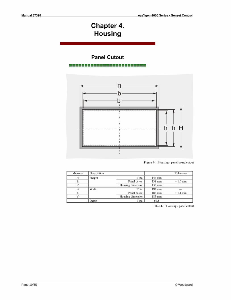
Figure 4-1: Housing - panel-board cutout
Measure Description Tolerance
H Height Total 144 mm --- h Panel cutout 138 mm + 1.0 mm h' Housing dimension 136 mm B Width Total 192 mm --- b Panel cutout 186 mm + 1.1 mm b' Housing dimension 185 mm Depth Total 60.5 ---
Table 4-1: Housing - panel cutout
Manual 37390 easYgen-1000 Series - Genset Control
© Woodward Page 11/55
Dimensions ≡≡≡≡≡≡≡≡≡≡≡≡≡≡≡≡≡≡≡≡≡≡≡≡≡
5857
5655
5453
5251
5049
4846
4544
4342
4140
3938
3736
3534
3332
3130
12
34
56
78
910
1112
1314
1516
1718
1920
2122
2324
2526
2728
29
47
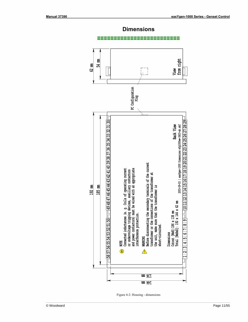
NOTE
Connected inductances (e. g. Coils of operating current
or undervoltage tripping devices, auxiliary contactors
and power contactors) must be wired with an appropriate
interference protection.
WARNING
Before disconnecting the secondary terminals of the current
transformer or the connections of the transformer at
the unit, make sure that the transformer is
short-circuited.
Dimensions
Cutout [WxH]:186 x 138 mm
Total [WxHxD]: 192 x 144 x 62 mm
144 mm136 mm
192 mm
185 mm
62 mm 54 mm
Back View
View
from right
PC Configuration
Plug
2003-09-03 | easYgen-1000 Dimensions eYg1000ww-3603-ab.skf
Figure 4-2: Housing - dimensions
Manual 37390 easYgen-1000 Series - Genset Control
Page 12/55 © Woodward
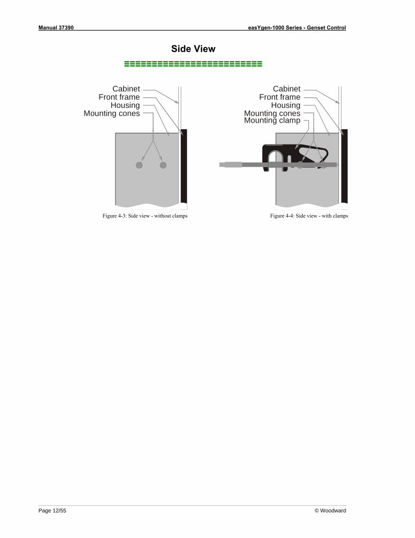
Side View ≡≡≡≡≡≡≡≡≡≡≡≡≡≡≡≡≡≡≡≡≡≡≡≡≡
CabinetFront frame
HousingMounting cones
Figure 4-3: Side view - without clamps
Cabinet
Front frameHousing
Mounting conesMounting clamp
Figure 4-4: Side view - with clamps
Manual 37390 easYgen-1000 Series - Genset Control
© Woodward Page 13/55
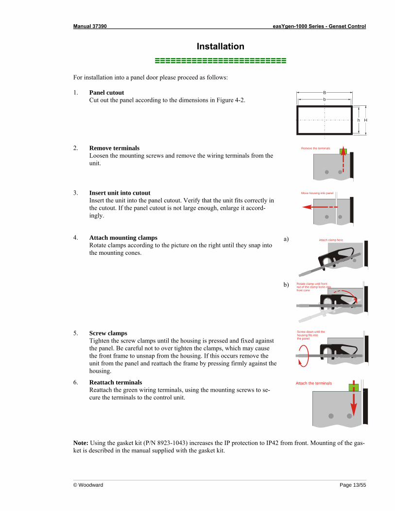
Installation ≡≡≡≡≡≡≡≡≡≡≡≡≡≡≡≡≡≡≡≡≡≡≡≡≡
For installation into a panel door please proceed as follows: 1. Panel cutout
Cut out the panel according to the dimensions in Figure 4-2.
b
h H
B
2. Remove terminals
Loosen the mounting screws and remove the wiring terminals from the unit.
Remove the terminals
3. Insert unit into cutout
Insert the unit into the panel cutout. Verify that the unit fits correctly in the cutout. If the panel cutout is not large enough, enlarge it accord-ingly.
Move housing into panel
a) Attach clamp here4. Attach mounting clamps
Rotate clamps according to the picture on the right until they snap into the mounting cones.
b) Rotate clamp until frontnut of the clamp locks intofront cone
5. Screw clamps
Tighten the screw clamps until the housing is pressed and fixed against the panel. Be careful not to over tighten the clamps, which may cause the front frame to unsnap from the housing. If this occurs remove the unit from the panel and reattach the frame by pressing firmly against the housing.
Screw down until thehousing fits into the panel
6. Reattach terminals
Reattach the green wiring terminals, using the mounting screws to se-cure the terminals to the control unit.
Attach the terminals
Note: Using the gasket kit (P/N 8923-1043) increases the IP protection to IP42 from front. Mounting of the gas-ket is described in the manual supplied with the gasket kit.
Manual 37390 easYgen-1000 Series - Genset Control
Page 14/55 © Woodward
Chapter 5. Wiring Diagrams - Overview
NOTE Please refer to manual 37392 "Operation Manual" for selection of the application mode. Depending on application different terminals will be utilized.
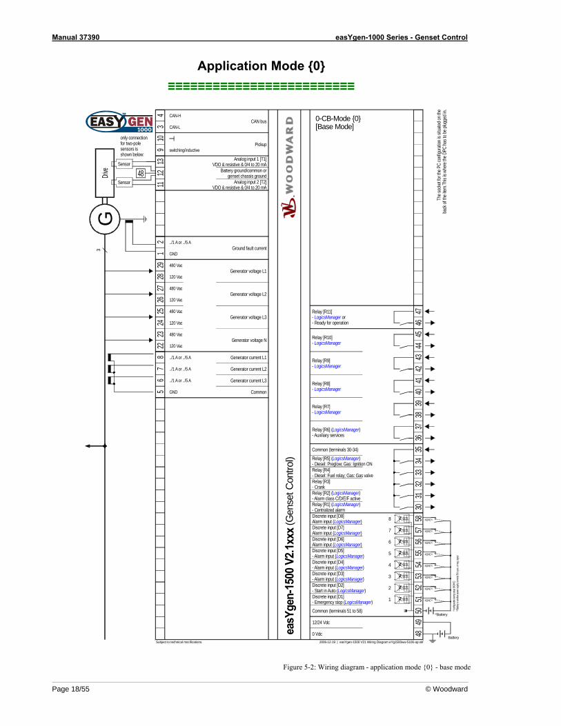
• Application mode {0} - [BM] - Base Mode - page 18
- Measuring of engine/generator parameters (i.e. voltages, currents, coolant temperature, oil pressure, etc.) - Engine start/stop
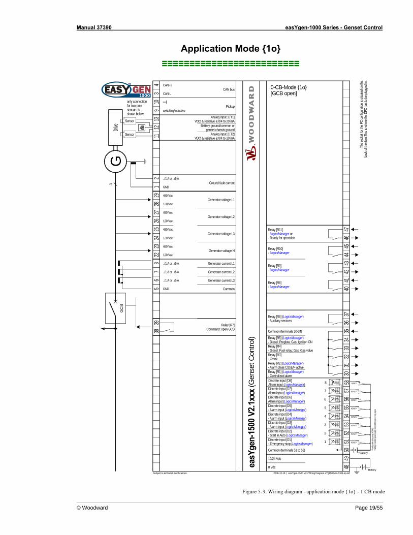
• Application mode {1o} - [GCB open] - 1-CB-Mode - page 19 - Measuring of engine/generator parameters (i.e. voltages, currents, coolant temperature, oil pressure, etc.) - Engine start/stop - Engine/generator protection (relay output to open GCB)
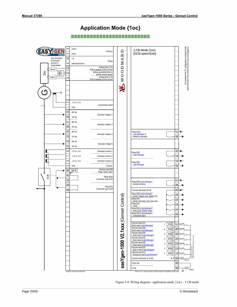
• Application mode {1oc} - [GCB open/close] - 1-CB-Mode - page 20
- Measuring of engine/generator parameters (i.e. voltages, currents, coolant temperature, oil pressure, etc.) - Engine start/stop - Engine/generator protection (relay output to open GCB) - GCB operation (relay output to close GCB)
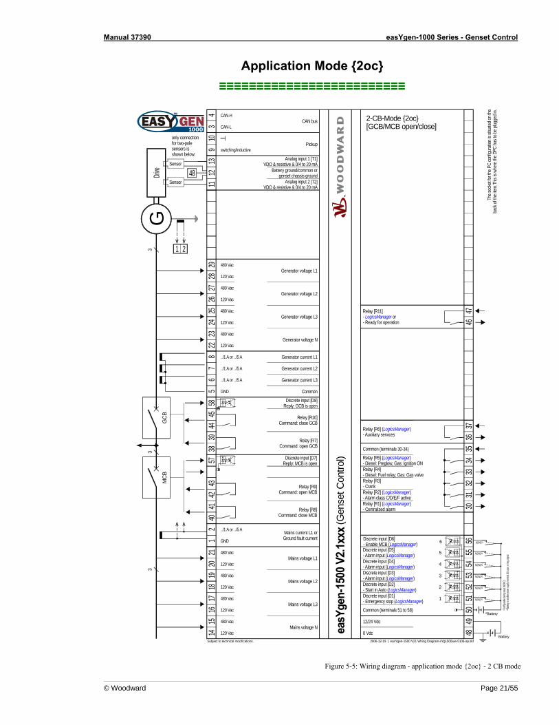
• Application mode {2oc} - [GCB/MCB open/close] - 2-CB-Mode - page 21
- Measuring of engine/generator parameters (i.e. voltages, currents, coolant temperature, oil pressure, etc.) - Engine start/stop - Engine/generator protection (relay output to open GCB) - GCB operation (relay output to close GCB) - MCB operation (relay output to open and close the MCB) - Mains failure detection (AMF auto mains failure operation) and automatic engine start/stop
Manual 37390 easYgen-1000 Series - Genset Control
© Woodward Page 15/55
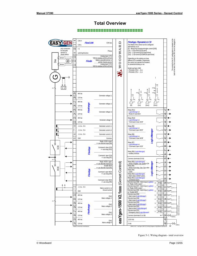
Total Overview ≡≡≡≡≡≡≡≡≡≡≡≡≡≡≡≡≡≡≡≡≡≡≡≡≡
G
1
12/24 Vdc
2006-12-19 | easYgen-1500 V21 Wiring Diagram eYg1500ww-5106-ap.skf
4
5
2
3
56
78
2829
1112
13
4849
5051
5253
5455
../1 A or ../5 A
0 Vdc
Drive
Subject to technical mocifications.
Generator current L3
Generator current L2
Generator current L1
Generator voltage L1
Pickup
Analog input 1 [T1]VDO & resistive & 0/4 to 20 mA
The s
ocke
t for t
he P
C co
nfigu
ratio
n is s
ituate
d on t
heba
ck of
the i
tem.T
his is
whe
re th
e DPC
has t
o be p
lugge
d in.
Common (terminals 51 to 58)
Discrete input [D2]- Start in Auto (LogicsManager)Discrete input [D1]- Emergency stop (LogicsManager)
Relay [R6] (LogicsManager)- Auxiliary services 36
37
34
CAN busCAN-H
CAN-L
Analog input 2 [T2]VDO & resistive & 0/4 to 20 mA
Battery ground/common orgenset chassis ground
109 switching/inductive
480 Vac
120 Vac
2627
Generator voltage L2480 Vac
120 Vac
2425
Generator voltage L3480 Vac
120 Vac
2223 480 Vac
120 VacGenerator voltage N
../1 A or ../5 A
../1 A or ../5 A
Common
Discrete input [D3]- Alarm input (LogicsManager)
Discrete input [D4]- Alarm input (LogicsManager)
Discrete input [D5]- Alarm input (LogicsManager)
3433
3235Common (terminals 30-34)
Relay [R5] (LogicsManager)- Diesel: Preglow; Gas: Ignition ONRelay [R4]- Diesel: Fuel relay; Gas: Gas valveRelay [R3]- Crank
31Relay [R2] (LogicsManager)- Alarm class C/D/E/F active
30Relay [R1] (LogicsManager)- Centralized alarm
Relay [R7]- LogicsManager or- "Command: open GCB" 38
39
Relay [R8]- LogicsManager or- "Command: close MCB" 40
41
Relay [R11]- LogicsManager or- Ready for operation 46
47
3
GND
Battery
configu
rable d
uring
setup
(NO/N
C)#1
NO/NC#1
NO/NC#1
NO/NC#1
NO/NC#1
#1
#2
Batte
ry or
anoth
er po
wer s
upply
; term
inal 50
is po
s. or n
eg. si
gnal
#2
NO/NC
Relay [R10]- LogicsManager or- "Command: close GCB" 44
45
Relay [R9]- LogicsManager or- "Command: open MCB" 4243
6 56Discrete input [D6] - Alarm input (LogMan)or "Enable MCB"
7 57Discrete input [D7] - Alarm input (LogMan)or "Reply: MCB is open"
8 58Discrete input [D8] - Alarm input (LogMan)or "Reply: GCB is open" NO/NC#1
NO/NC#1
NO/NC#1
33
MCB
Reply: MCB is open=> use discrete input [D7]
Enable MCB=> use discrete input [D6]
Command: open MCB=> use relay [R9]
Mains current L1 orGround current
../1 A or ../5 A21
2021
1819
1617
1415
{2oc}Mains voltage L1
480 Vac
120 Vac
{2oc}Mains voltage L2
480 Vac
120 Vac
{2oc}Mains voltage L3
480 Vac
120 Vac
480 Vac
120 Vac
GND
GCB
Reply: GCB is open=> use discrete input [D8]
Command: close GCB=> use relay [R10]
{2oc}Mains voltage N
The Mode of the control can be configuredalternatively as an:{0} - Measuring transducer/engine control [0CB]{1o} - 1-CB-control [GCB open]{1oc} - 1-CB-control [GCB open/close]{2oc} - 2-CB-control [GCB/MCB open/close]
Depending on the setting you havedifferent I/O's available, respectivelythe control can operate the breakersfor protection/closing or not.
Model easYgen-1500- P/N 8440-1750 = ../5 A- P/N 8440-1751 = ../1 A
easY
gen-
1500
V2.
1xxx
FlexApp / DynamicsLCD
Flex
Rang
e
FlexIn
FlexCAN
Flex
Rang
e
Logi
csM
anag
erLo
gics
Man
ager
Command: close MCB=> use relay [R8]
Command: open GCB=> use relay [R7]
Flex
App
Flex
App
1 2
3
3
G1
{0}
GCB3
3
{1o}
GCB3
3
{1oc}
3
1
MCB
GCB3
3
{2oc}
S/S
G1
S/S
G1
S/S
G1
S/S
open
open
/clo
se
open
/clo
se
(Gen
set C
ontro
l)
Battery
Sensor
Sensor
48
only connectionfor two-polesensors is shown below:
Figure 5-1: Wiring diagram - total overview
Manual 37390 easYgen-1000 Series - Genset Control
Page 16/55 © Woodward
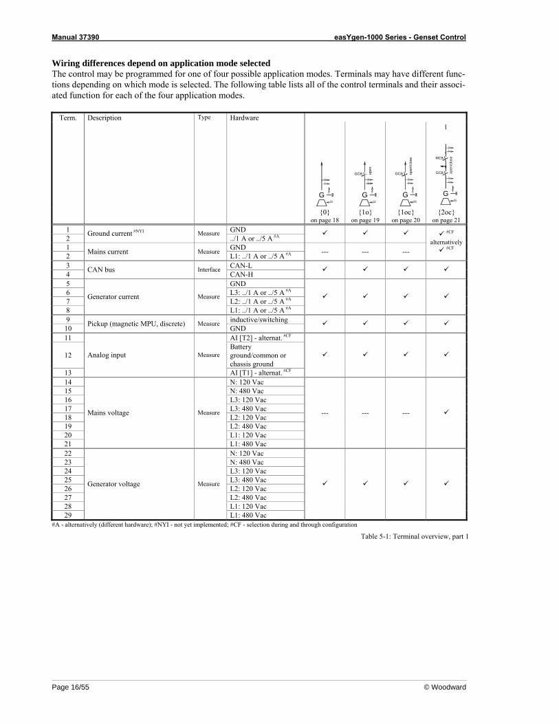
Wiring differences depend on application mode selected The control may be programmed for one of four possible application modes. Terminals may have different func-tions depending on which mode is selected. The following table lists all of the control terminals and their associ-ated function for each of the four application modes.
Term. Description Type Hardware
3
3
G 1
S/S
3
3
GCB
G 1
S/S
open
GCB3
3
G 1
S/S
open
/clo
se
3
1
MCB
GCB3
3
G 1
S/S
open
/clo
se
{0}
on page 18 {1o}
on page 19 {1oc}
on page 20 {2oc}
on page 21 1 GND 2
Ground current #NYI Measure ../1 A or ../5 A #A
1 GND 2 Mains current Measure
L1: ../1 A or ../5 A #A --- --- ---
#CF alternatively
#CF
3 CAN-L 4 CAN bus Interface
CAN-H
5 GND 6 L3: ../1 A or ../5 A #A 7 L2: ../1 A or ../5 A #A 8
Generator current Measure
L1: ../1 A or ../5 A #A
9 inductive/switching 10 Pickup (magnetic MPU, discrete) Measure
GND
11 AI [T2] - alternat. #CF
12 Battery ground/common or chassis ground
13
Analog input Measure
AI [T1] - alternat. #CF
14 N: 120 Vac 15 N: 480 Vac 16 L3: 120 Vac 17 L3: 480 Vac 18 L2: 120 Vac 19 L2: 480 Vac 20 L1: 120 Vac 21
Mains voltage Measure
L1: 480 Vac
--- --- ---
22 N: 120 Vac 23 N: 480 Vac 24 L3: 120 Vac 25 L3: 480 Vac 26 L2: 120 Vac 27 L2: 480 Vac 28 L1: 120 Vac 29
Generator voltage Measure
L1: 480 Vac
#A - alternatively (different hardware); #NYI - not yet implemented; #CF - selection during and through configuration Table 5-1: Terminal overview, part 1
Manual 37390 easYgen-1000 Series - Genset Control
© Woodward Page 17/55
Term. Description Type Hardware
3
3
G 1
S/S
3
3
GCB
G1
S/S
open
GCB3
3
G 1
S/S
open
/clo
se
3
1
MCB
GCB3
3
G 1
S/S
open
/clo
se
{0}
on page 18 {1o}
on page 19 {1oc}
on page 20 {2oc}
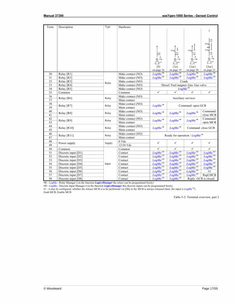
on page 21 30 Relay [R1] Make contact (NO) LogMa #R LogMa #R LogMa #R LogMa #R 31 Relay [R2] Make contact (NO) LogMa #R LogMa #R LogMa #R LogMa #R 32 Relay [R3] Make contact (NO) Crank 33 Relay [R4] Make contact (NO) Diesel: Fuel magnet; Gas: Gas valve 34 Relay [R5] Make contact (NO) LogMa #R 35 Common
Relay
Common 36 Make contact (NO) 37 Relay [R6] Relay
Main contact Auxiliary services
38 Make contact (NO) 39 Relay [R7] Relay
Main contact LogMa #R Command: open GCB
40 Make contact (NO) 41 Relay [R8] Relay
Main contact LogMa #R LogMa #R LogMa #R Command: close MCB
42 Make contact (NO) 43 Relay [R9] Relay
Main contact LogMa #R LogMa #R LogMa #R Command: open MCB
44 Make contact (NO) 45 Relay [R10] Relay
Main contact LogMa #R LogMa #R Command: close GCB
46 Make contact (NO) 47 Relay [R11] Relay
Main contact Ready for operation / LogMa #R
48 0 Vdc 49 Power supply Supply
12/24 Vdc
50 Common Common 51 Discrete input [D1] Contact LogMa #D LogMa #D LogMa #D LogMa #D 52 Discrete input [D2] Contact LogMa #D LogMa #D LogMa #D LogMa #D 53 Discrete input [D3] Contact LogMa #D LogMa #D LogMa #D LogMa #D 54 Discrete input [D4] Contact LogMa #D LogMa #D LogMa #D LogMa #D 55 Discrete input [D5] Contact LogMa #D LogMa #D LogMa #D LogMa #D 56 Discrete input [D6] Contact LogMa #D LogMa #D LogMa #D #1 57 Discrete input [D7] Contact LogMa #D LogMa #D LogMa #D Repl:MCB58 Discrete input [D8]
Input
Contact LogMa #D LogMa #D Reply: GCB is closed #R - LogMa - Relay Manager (via the function LogicsManager the relays can be programmed freely) #D - LogMa - Discrete Input Manager (via the function LogicsManager this discrete inputs can be programmed freely) #1 - it may be configured, whether the release MCB is to be performed via [D6] or the MCB is always released (then, the input is LogMa #D) Enab.MCB..Enable MCB
Table 5-2: Terminal overview, part 2
Manual 37390 easYgen-1000 Series - Genset Control
Page 18/55 © Woodward
Application Mode {0} ≡≡≡≡≡≡≡≡≡≡≡≡≡≡≡≡≡≡≡≡≡≡≡≡≡
G
1
12/24 Vdc
2006-12-19 | easYgen-1500 V21 Wiring Diagram eYg1500ww-5106-ap.skf
4
5
2
3
56
78
2829
1112
13
4849
5051
5253
5455
../1 A or ../5 A
0 Vdc
Drive
Subject to technical mocifications.
Generator current L3
Generator current L2
Generator current L1
Generator voltage L1
Pickup
Analog input 1 [T1]VDO & resistive & 0/4 to 20 mA
The s
ocke
t for t
he P
C co
nfigu
ratio
n is s
ituate
d on t
heba
ck of
the i
tem.T
his is
whe
re th
e DPC
has t
o be p
lugge
d in.
Common (terminals 51 to 58)
Discrete input [D2]- Start in Auto (LogicsManager)Discrete input [D1]- Emergency stop (LogicsManager)
Relay [R6] (LogicsManager)- Auxiliary services 36
37
34
CAN busCAN-H
CAN-L
Analog input 2 [T2]VDO & resistive & 0/4 to 20 mA
Battery ground/common orgenset chassis ground
109 switching/inductive
480 Vac
120 Vac
2627
Generator voltage L2480 Vac
120 Vac
2425
Generator voltage L3480 Vac
120 Vac
2223 480 Vac
120 VacGenerator voltage N
../1 A or ../5 A
../1 A or ../5 A
Common
Discrete input [D3]- Alarm input (LogicsManager)
Discrete input [D4]- Alarm input (LogicsManager)
Discrete input [D5]- Alarm input (LogicsManager)
3433
3235Common (terminals 30-34)
Relay [R5] (LogicsManager)- Diesel: Preglow; Gas: Ignition ONRelay [R4]- Diesel: Fuel relay; Gas: Gas valveRelay [R3]- Crank
31Relay [R2] (LogicsManager)- Alarm class C/D/E/F active
30Relay [R1] (LogicsManager)- Centralized alarm
Relay [R11]- LogicsManager or- Ready for operation 46
47
3
GND
Relay [R10]- LogicsManager 44
45
Relay [R9]- LogicsManager 42
43
6 56Discrete input [D6]Alarm input (LogicsManager)
7 57Discrete input [D7]Alarm input (LogicsManager)
8 58Discrete input [D8]Alarm input (LogicsManager)
Battery
NO/NC#1
configu
rable d
uring
setup
(NO/N
C)#1
NO/NC#1
NO/NC#1
NO/NC#1
NO/NC#1
NO/NC#1
NO/NC#1
#1
#2
Batte
ry or
anoth
er po
wer s
upply
; term
inal 50
is po
s. or n
eg. si
gnal
#2
21
../1 A or ../5 A
GND
NO/NC
easY
gen-
1500
V2.
1xxx
Relay [R8]- LogicsManager 40
41Relay [R7]- LogicsManager 38
39
(Gen
set C
ontro
l)
0-CB-Mode {0}[Base Mode]
Ground fault current
Battery
Sensor
Sensor
48
only connectionfor two-polesensors is shown below:
Figure 5-2: Wiring diagram - application mode {0} - base mode
Manual 37390 easYgen-1000 Series - Genset Control
© Woodward Page 19/55
Application Mode {1o} ≡≡≡≡≡≡≡≡≡≡≡≡≡≡≡≡≡≡≡≡≡≡≡≡≡
G
1
12/24 Vdc
2006-12-19 | easYgen-1500 V21 Wiring Diagram eYg1500ww-5106-ap.skf
4
5
2
3
56
78
2829
1112
13
4849
5051
5253
5455
../1 A or ../5 A
0 Vdc
Drive
Subject to technical mocifications.
Generator current L3
Generator current L2
Generator current L1
Generator voltage L1
Pickup
Analog input 1 [T1]VDO & resistive & 0/4 to 20 mA
The s
ocke
t for t
he P
C co
nfigu
ratio
n is s
ituate
d on t
heba
ck of
the i
tem.T
his is
whe
re th
e DPC
has t
o be p
lugge
d in.
Common (terminals 51 to 58)
Discrete input [D2]- Start in Auto (LogicsManager)Discrete input [D1]- Emergency stop (LogicsManager)
Relay [R6] (LogicsManager)- Auxiliary services 36
37
34
CAN busCAN-H
CAN-L
Analog input 2 [T2]VDO & resistive & 0/4 to 20 mA
Battery ground/common orgenset chassis ground
109 switching/inductive
480 Vac
120 Vac
2627
Generator voltage L2480 Vac
120 Vac
2425
Generator voltage L3480 Vac
120 Vac
2223 480 Vac
120 VacGenerator voltage N
../1 A or ../5 A
../1 A or ../5 A
Common
Discrete input [D3]- Alarm input (LogicsManager)
Discrete input [D4]- Alarm input (LogicsManager)
Discrete input [D5]- Alarm input (LogicsManager)
3433
3235Common (terminals 30-34)
Relay [R5] (LogicsManager)- Diesel: Preglow; Gas: Ignition ONRelay [R4]- Diesel: Fuel relay; Gas: Gas valveRelay [R3]- Crank
31Relay [R2] (LogicsManager)- Alarm class C/D/E/F active
30Relay [R1] (LogicsManager)- Centralized alarm
Relay [R11]- LogicsManager or- Ready for operation 46
47
3
GND
Battery
configu
rable d
uring
setup
(NO/N
C)#1
NO/NC#1
NO/NC#1
NO/NC#1
NO/NC#1
#1
#2
Batte
ry or
anoth
er po
wer s
upply
; term
inal 50
is po
s. or n
eg. si
gnal
#2
NO/NC
easY
gen-
1500
V2.
1xxx
GCB
Relay [R9]- LogicsManager 4243
6
7
5657
Discrete input [D6]Alarm input (LogicsManager)
Discrete input [D7]Alarm input (LogicsManager) #1
NO/NC#1
Ground fault current
21
../1 A or ../5 A
GND
NO/NC
Relay [R8]- LogicsManager 40
41
3839 Relay [R7]
Command: open GCB
Relay [R10]- LogicsManager 44
45
(Gen
set C
ontro
l)
0-CB-Mode {1o}[GCB open]
Battery
Sensor
Sensor
48
only connectionfor two-polesensors is shown below:
Discrete input [D8]Alarm input (LogicsManager) 8 58 NO/NC#1
Figure 5-3: Wiring diagram - application mode {1o} - 1 CB mode
Manual 37390 easYgen-1000 Series - Genset Control
Page 20/55 © Woodward
Application Mode {1oc} ≡≡≡≡≡≡≡≡≡≡≡≡≡≡≡≡≡≡≡≡≡≡≡≡≡
G
1
12/24 Vdc
2006-12-19 | easYgen-1500 V21 Wiring Diagram eYg1500ww-5106-ap.skf
4
5
2
3
4445
585
67
828
2911
1213
4849
5051
5253
5455
../1 A or ../5 A
0 Vdc
Drive
Subject to technical mocifications.
GCB
Discrete input [D8]Reply: GCB is open
Generator current L3
Generator current L2
Generator current L1
Generator voltage L1
Pickup
Analog input 1 [T1]VDO & resistive & 0/4 to 20 mA
Relay [R10]Command: close GCB
The s
ocke
t for t
he P
C co
nfigu
ratio
n is s
ituate
d on t
heba
ck of
the i
tem.T
his is
whe
re th
e DPC
has t
o be p
lugge
d in.
Common (terminals 51 to 58)
Discrete input [D2]- Start in Auto (LogicsManager)Discrete input [D1]- Emergency stop (LogicsManager)
Relay [R6] (LogicsManager)- Auxiliary services 36
37
34
CAN busCAN-H
CAN-L
Analog input 2 [T2]VDO & resistive & 0/4 to 20 mA
Battery ground/common orgenset chassis ground
109 switching/inductive
480 Vac
120 Vac
2627
Generator voltage L2480 Vac
120 Vac
2425
Generator voltage L3480 Vac
120 Vac
2223 480 Vac
120 VacGenerator voltage N
../1 A or ../5 A
../1 A or ../5 A
Common
Discrete input [D3]- Alarm input (LogicsManager)
Discrete input [D4]- Alarm input (LogicsManager)
Discrete input [D5]- Alarm input (LogicsManager)
3433
3235Common (terminals 30-34)
Relay [R5] (LogicsManager)- Diesel: Preglow; Gas: Ignition ONRelay [R4]- Diesel: Fuel relay; Gas: Gas valveRelay [R3]- Crank
31Relay [R2] (LogicsManager)- Alarm class C/D/E/F active
30Relay [R1] (LogicsManager)- Centralized alarm
Relay [R11]- LogicsManager or- Ready for operation 46
47
3
GND
Relay [R9]- LogicsManager 42
43
6
7
5657
Discrete input [D6]Alarm input (LogicsManager)
Discrete input [D7]Alarm input (LogicsManager)
Battery
configu
rable d
uring
setup
(NO/N
C)#1
NO/NC#1
NO/NC#1
NO/NC#1
NO/NC#1
#1
#2
Batte
ry or
anoth
er po
wer s
upply
; term
inal 50
is po
s. or n
eg. si
gnal
#2
#1
NO/NC#1
Ground fault current
21
../1 A or ../5 A
GND
NO/NC
NO/NC
easY
gen-
1500
V2.
1xxx
Relay [R8]- LogicsManager 40
41
3839 Relay [R7]
Command: open GCB
(Gen
set C
ontro
l)
1-CB-Mode {1oc}[GCB open/close]
Battery
Sensor
Sensor
48
only connectionfor two-polesensors is shown below:
Figure 5-4: Wiring diagram - application mode {1oc} - 1 CB mode
Manual 37390 easYgen-1000 Series - Genset Control
© Woodward Page 21/55
Application Mode {2oc} ≡≡≡≡≡≡≡≡≡≡≡≡≡≡≡≡≡≡≡≡≡≡≡≡≡
33
G
1
12/24 Vdc
2006-12-19 | easYgen-1500 V21 Wiring Diagram eYg1500ww-5106-ap.skf
4
5
2
3
43
56
575
67
828
2911
1213
4849
5051
5253
5455
../1 A or ../5 A
0 Vdc
Drive
MCB
Subject to technical mocifications.
Generator current L3
Generator current L2
Generator current L1
Generator voltage L1
Pickup
Analog input 1 [T1]VDO & resistive & 0/4 to 20 mA
The s
ocke
t for t
he P
C co
nfigu
ratio
n is s
ituate
d on t
heba
ck of
the i
tem.T
his is
whe
re th
e DPC
has t
o be p
lugge
d in.
Discrete input [D7]Reply: MCB is open
Relay [R9]Command: open MCB
Common (terminals 51 to 58)
Discrete input [D2]- Start in Auto (LogicsManager)Discrete input [D1]- Emergency stop (LogicsManager)
Relay [R6] (LogicsManager)- Auxiliary services 36
37
34
CAN busCAN-H
CAN-L
Analog input 2 [T2]VDO & resistive & 0/4 to 20 mA
Battery ground/common orgenset chassis ground
109 switching/inductive
480 Vac
120 Vac
2627
Generator voltage L2480 Vac
120 Vac
2425
Generator voltage L3480 Vac
120 Vac
2223 480 Vac
120 VacGenerator voltage N
../1 A or ../5 A
../1 A or ../5 A
Common
Mains current L1 orGround fault current
../1 A or ../5 A
422
120
2118
1916
1714
15
Mains voltage L1480 Vac
120 Vac
Mains voltage L2480 Vac
120 Vac
Mains voltage L3480 Vac
120 Vac
480 Vac
120 VacMains voltage N
Discrete input [D3]- Alarm input (LogicsManager)
Discrete input [D4]- Alarm input (LogicsManager)
Discrete input [D5]- Alarm input (LogicsManager)
3433
3235Common (terminals 30-34)
Relay [R5] (LogicsManager)- Diesel: Preglow; Gas: Ignition ONRelay [R4]- Diesel: Fuel relay; Gas: Gas valveRelay [R3]- Crank
31Relay [R2] (LogicsManager)- Alarm class C/D/E/F active
30Relay [R1] (LogicsManager)- Centralized alarm
Relay [R11]- LogicsManager or- Ready for operation 46
47
3
GND
GND
Battery
configu
rable d
uring
setup
(NO/N
C)#1
NO/NC#1
NO/NC#1
NO/NC#1
NO/NC#1
#1
#2
Batte
ry or
anoth
er po
wer s
upply
; term
inal 50
is po
s. or n
eg. si
gnal
#2
NO/NC
4445
58
GCB
Discrete input [D8]Reply: GCB is open
Relay [R10]Command: close GCB
easY
gen-
1500
V2.
1xxx
1 2
3839 Relay [R7]
Command: open GCB
4140
Relay [R8]Command: close MCB
(Gen
set C
ontro
l)
2-CB-Mode {2oc}[GCB/MCB open/close]
Battery
Sensor
Sensor
48
only connectionfor two-polesensors is shown below:
6Discrete input [D6]- Enable MCB (LogicsManager) NO/NC#1
Figure 5-5: Wiring diagram - application mode {2oc} - 2 CB mode
Manual 37390 easYgen-1000 Series - Genset Control
Page 22/55 © Woodward
Chapter 6. Connections
WARNING All technical data and ratings indicated in this chapter are not definite! Only the values indicated in Chapter 7: Technical Data on page 48 are valid!
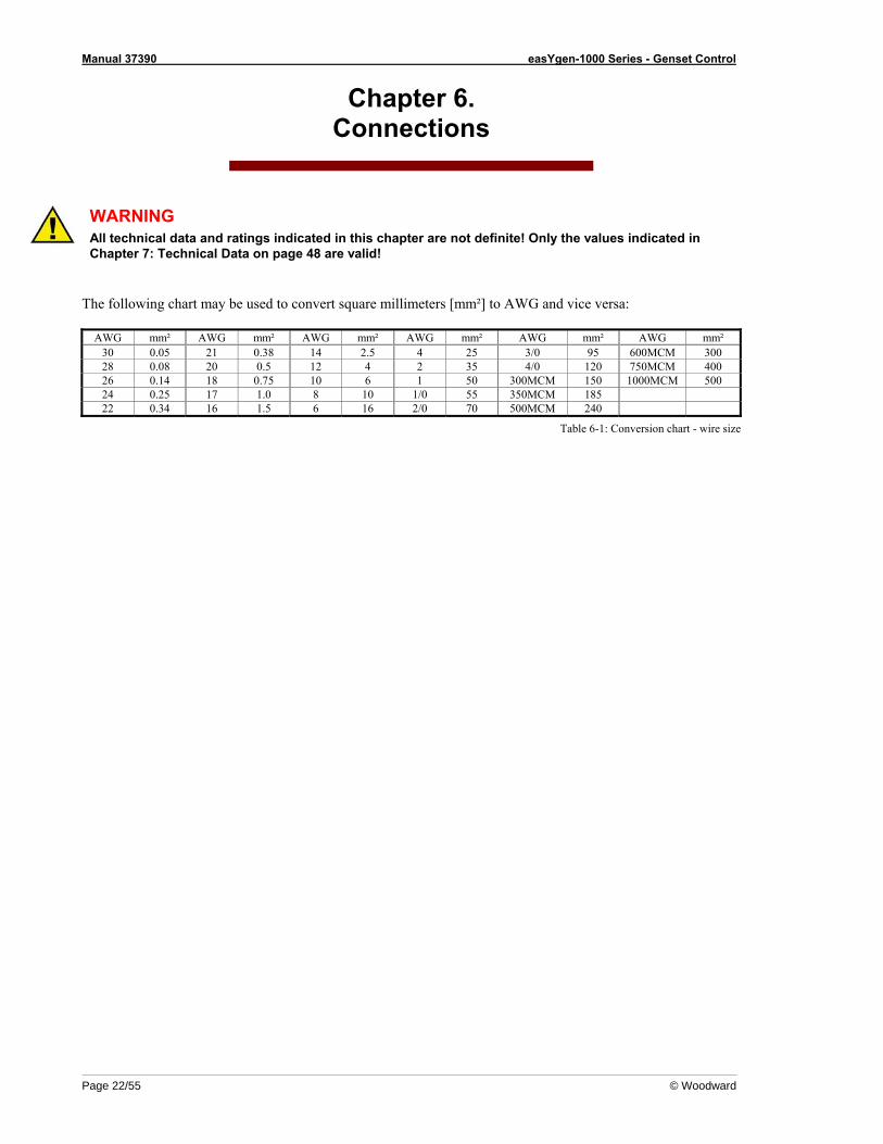
The following chart may be used to convert square millimeters [mm²] to AWG and vice versa:
AWG mm² AWG mm² AWG mm² AWG mm² AWG mm² AWG mm² 30 0.05 21 0.38 14 2.5 4 25 3/0 95 600MCM 300 28 0.08 20 0.5 12 4 2 35 4/0 120 750MCM 400 26 0.14 18 0.75 10 6 1 50 300MCM 150 1000MCM 500 24 0.25 17 1.0 8 10 1/0 55 350MCM 185 22 0.34 16 1.5 6 16 2/0 70 500MCM 240
Table 6-1: Conversion chart - wire size
Manual 37390 easYgen-1000 Series - Genset Control
© Woodward Page 23/55
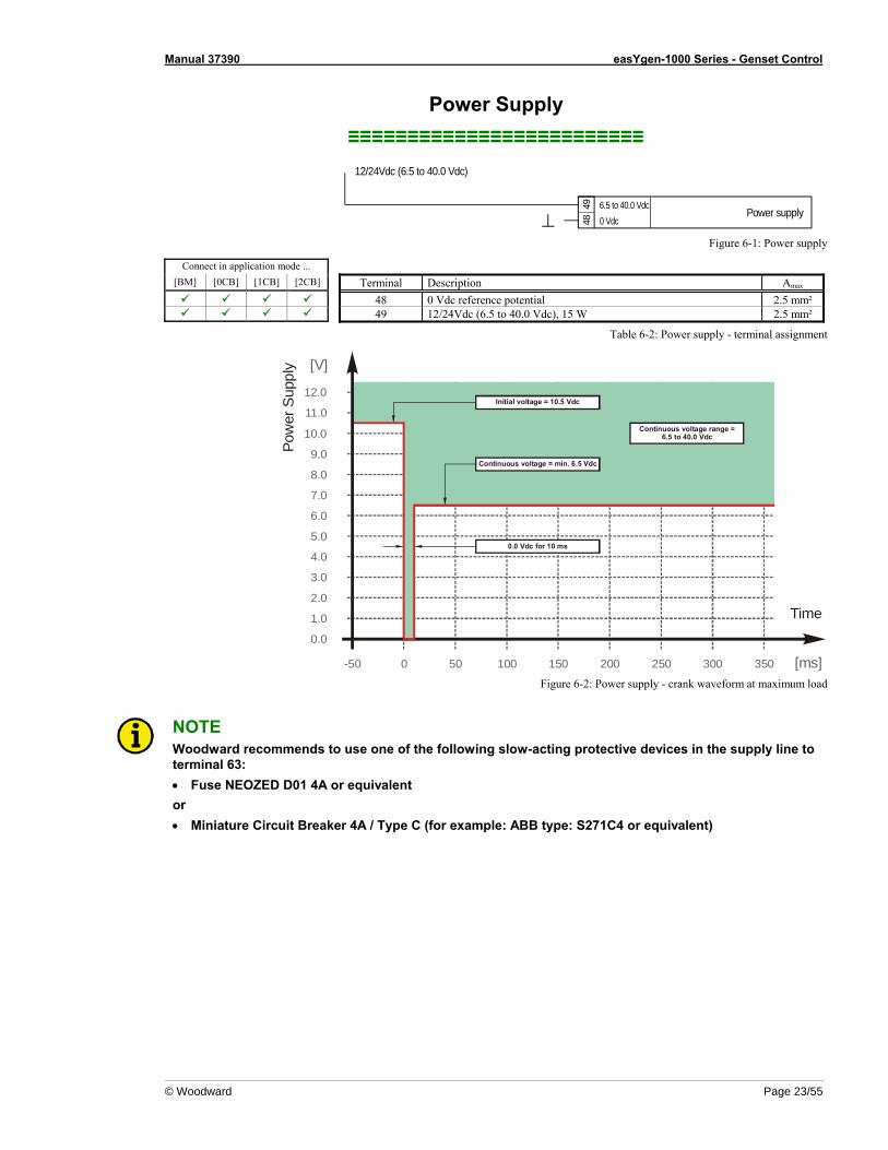
Power Supply ≡≡≡≡≡≡≡≡≡≡≡≡≡≡≡≡≡≡≡≡≡≡≡≡≡
Power supply4948 0 Vdc
12/24Vdc (6.5 to 40.0 Vdc)
6.5 to 40.0 Vdc
Figure 6-1: Power supply
Connect in application mode ... [BM] [0CB] [1CB] [2CB] Terminal Description Amax
48 0 Vdc reference potential 2.5 mm² 49 12/24Vdc (6.5 to 40.0 Vdc), 15 W 2.5 mm²
Table 6-2: Power supply - terminal assignment
[ms]-50 0 50 100 150 200 250 300 350
[V]
9.0
10.0
11.0
12.0
Pow
er S
uppl
y
8.0
7.0
6.0
5.0
4.0
3.0
2.0
1.0
0.0
Time
Initial voltage = 10.5 Vdc
0.0 Vdc for 10 ms
Continuous voltage = min. 6.5 Vdc
Continuous voltage range =6.5 to 40.0 Vdc
Figure 6-2: Power supply - crank waveform at maximum load
NOTE Woodward recommends to use one of the following slow-acting protective devices in the supply line to terminal 63: • Fuse NEOZED D01 4A or equivalent or • Miniature Circuit Breaker 4A / Type C (for example: ABB type: S271C4 or equivalent)
Manual 37390 easYgen-1000 Series - Genset Control
Page 24/55 © Woodward
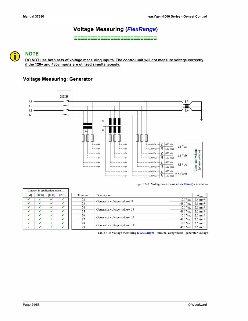
Voltage Measuring (FlexRange) ≡≡≡≡≡≡≡≡≡≡≡≡≡≡≡≡≡≡≡≡≡≡≡≡≡
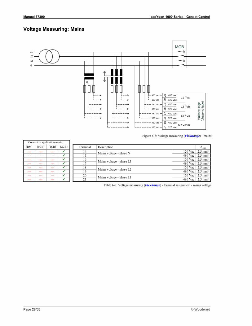
NOTE DO NOT use both sets of voltage measuring inputs. The control unit will not measure voltage correctly if the 120v and 480v inputs are utilized simultaneously.
Voltage Measuring: Generator
L1L2L3N
Gen
erat
or v
olta
ge(p
hase
vol
tage
)
GCB
26
N / Vcom
2728
29 L1 / Va
L2 / Vb
L3 / Vc23
2425
22
480 Vac
120 Vac
120 Vac
480 Vac
120 Vac
480 Vac
120 Vac
480 Vac
480 Vac
120 Vac
480 Vac
120 Vac
480 Vac
120 Vac
480 Vac
120 Vac
G
3~
Figure 6-3: Voltage measuring (FlexRange) - generator
Connect in application mode ... [BM] [0CB] [1CB] [2CB] Terminal Description Amax
22 120 Vac 2.5 mm² 23
Generator voltage - phase N 480 Vac 2.5 mm²
24 120 Vac 2.5 mm² 25 Generator voltage - phase L3 480 Vac 2.5 mm² 26 120 Vac 2.5 mm² 27 Generator voltage - phase L2 480 Vac 2.5 mm² 28 120 Vac 2.5 mm² 29 Generator voltage - phase L1 480 Vac 2.5 mm²
Table 6-3: Voltage measuring (FlexRange) - terminal assignment - generator voltage
Manual 37390 easYgen-1000 Series - Genset Control
© Woodward Page 25/55
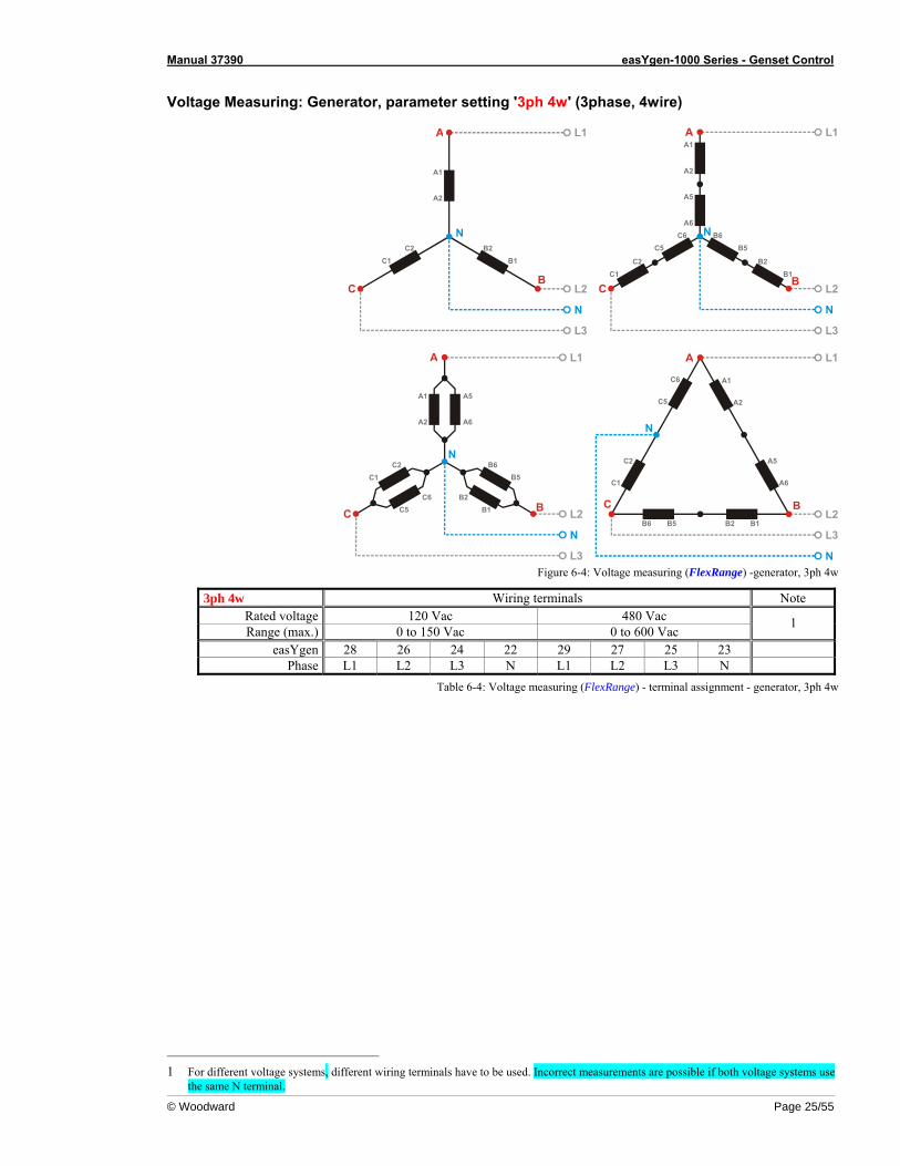
Voltage Measuring: Generator, parameter setting '3ph 4w' (3phase, 4wire)
L1
L2
N
L3
N
A1
A2
A
B
B2B1
C
C2C1
L1
L2
N
L3
N
A1
A2
A
B
C6C5
B6B5
A5
A6
B2B1
C
C2C1
L1
L2
N
L3
N
A1
A2
A
B
B6B5
A5
A6
CC6
C5B2
B1
C2C1
L1
L2
L3
N
N
B1B2
C6
C5
A1
A2
B5B6
A
BC
C2
C1
A5
A6
Figure 6-4: Voltage measuring (FlexRange) -generator, 3ph 4w
3ph 4w Wiring terminals Note Rated voltage 120 Vac 480 Vac Range (max.) 0 to 150 Vac 0 to 600 Vac
1
easYgen 28 26 24 22 29 27 25 23 Phase L1 L2 L3 N L1 L2 L3 N
Table 6-4: Voltage measuring (FlexRange) - terminal assignment - generator, 3ph 4w
1 For different voltage systems, different wiring terminals have to be used. Incorrect measurements are possible if both voltage systems use
the same N terminal.
Manual 37390 easYgen-1000 Series - Genset Control
Page 26/55 © Woodward
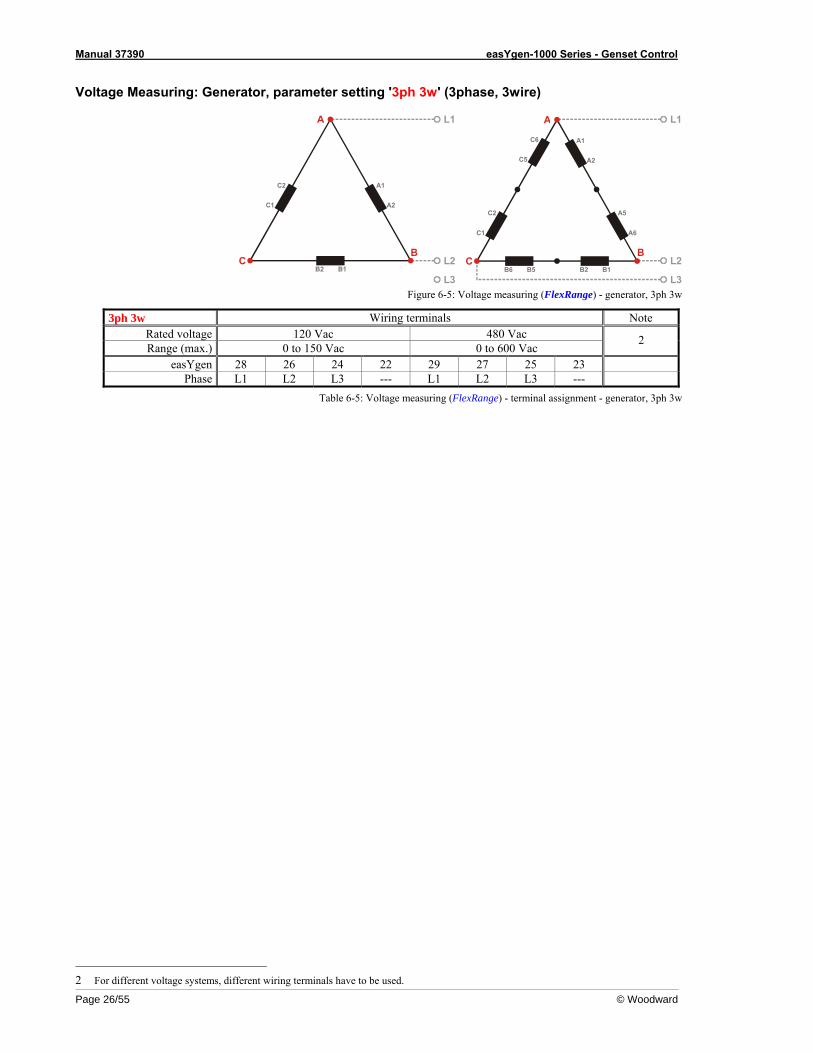
Voltage Measuring: Generator, parameter setting '3ph 3w' (3phase, 3wire)
L1
L2
L3B2
C2
C1
A1
A2
B1
A
BC
L1
L2
L3B1B2
C6
C5
A1
A2
B5B6
A
BC
C2
C1
A5
A6
Figure 6-5: Voltage measuring (FlexRange) - generator, 3ph 3w
3ph 3w Wiring terminals Note Rated voltage 120 Vac 480 Vac Range (max.) 0 to 150 Vac 0 to 600 Vac
2
easYgen 28 26 24 22 29 27 25 23 Phase L1 L2 L3 --- L1 L2 L3 ---
Table 6-5: Voltage measuring (FlexRange) - terminal assignment - generator, 3ph 3w
2 For different voltage systems, different wiring terminals have to be used.
Manual 37390 easYgen-1000 Series - Genset Control
© Woodward Page 27/55
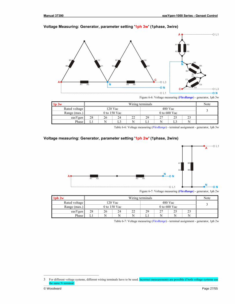
Voltage Measuring: Generator, parameter setting '1ph 3w' (1phase, 3wire)
L3
N
L1
N
B5
B6
C2
C1
A2A1A
B1
B2
C6
C5
A6A5
C
L1
L3N
N
C
A1
A2
A
B6B5
A5
A6
C6C5
B2B1C2
C1
Figure 6-6: Voltage measuring (FlexRange) - generator, 1ph 3w
1p 3w Wiring terminals Note Rated voltage 120 Vac 480 Vac Range (max.) 0 to 150 Vac 0 to 600 Vac
3
easYgen 28 26 24 22 29 27 25 23 Phase L1 N L3 N L1 N L3 N
Table 6-6: Voltage measuring (FlexRange) - terminal assignment - generator, 1ph 3w
Voltage measuring: Generator, parameter setting '1ph 2w' (1phase, 2wire)
N
L1
NA2A1
AA6A5
L1
NN
B5
B6
A1
A2
A
Figure 6-7: Voltage measuring (FlexRange) - generator, 1ph 2w
1ph 2w Wiring terminals Note Rated voltage 120 Vac 480 Vac Range (max.) 0 to 150 Vac 0 to 600 Vac
3
easYgen 28 26 24 22 29 27 25 23 Phase L1 N N N L1 N N N
Table 6-7: Voltage measuring (FlexRange) - terminal assignment - generator, 1ph 2w
3 For different voltage systems, different wiring terminals have to be used. Incorrect measurements are possible if both voltage systems use
the same N terminal.
Manual 37390 easYgen-1000 Series - Genset Control
Page 28/55 © Woodward
Voltage Measuring: Mains
L1L2L3N
Mai
ns v
olta
ge(p
hase
vol
tage
)
MCB
18
N / Vcom
1920
21 L1 / Va
L2 / Vb
L3 / Vc
1516
1714
480 Vac
120 Vac
120 Vac
480 Vac
120 Vac
480 Vac
120 Vac
480 Vac
480 Vac
120 Vac
480 Vac
120 Vac
480 Vac
120 Vac
480 Vac
120 Vac
Figure 6-8: Voltage measuring (FlexRange) - mains
Connect in application mode ... [BM] [0CB] [1CB] [2CB] Terminal Description Amax --- --- --- 14 120 Vac 2.5 mm²--- --- --- 15
Mains voltage - phase N 480 Vac 2.5 mm²
--- --- --- 16 120 Vac 2.5 mm²--- --- --- 17 Mains voltage - phase L3 480 Vac 2.5 mm²--- --- --- 18 120 Vac 2.5 mm²--- --- --- 19 Mains voltage - phase L2 480 Vac 2.5 mm²--- --- --- 20 120 Vac 2.5 mm²--- --- --- 21 Mains voltage - phase L1 480 Vac 2.5 mm²
Table 6-8: Voltage measuring (FlexRange) - terminal assignment - mains voltage
Manual 37390 easYgen-1000 Series - Genset Control
© Woodward Page 29/55
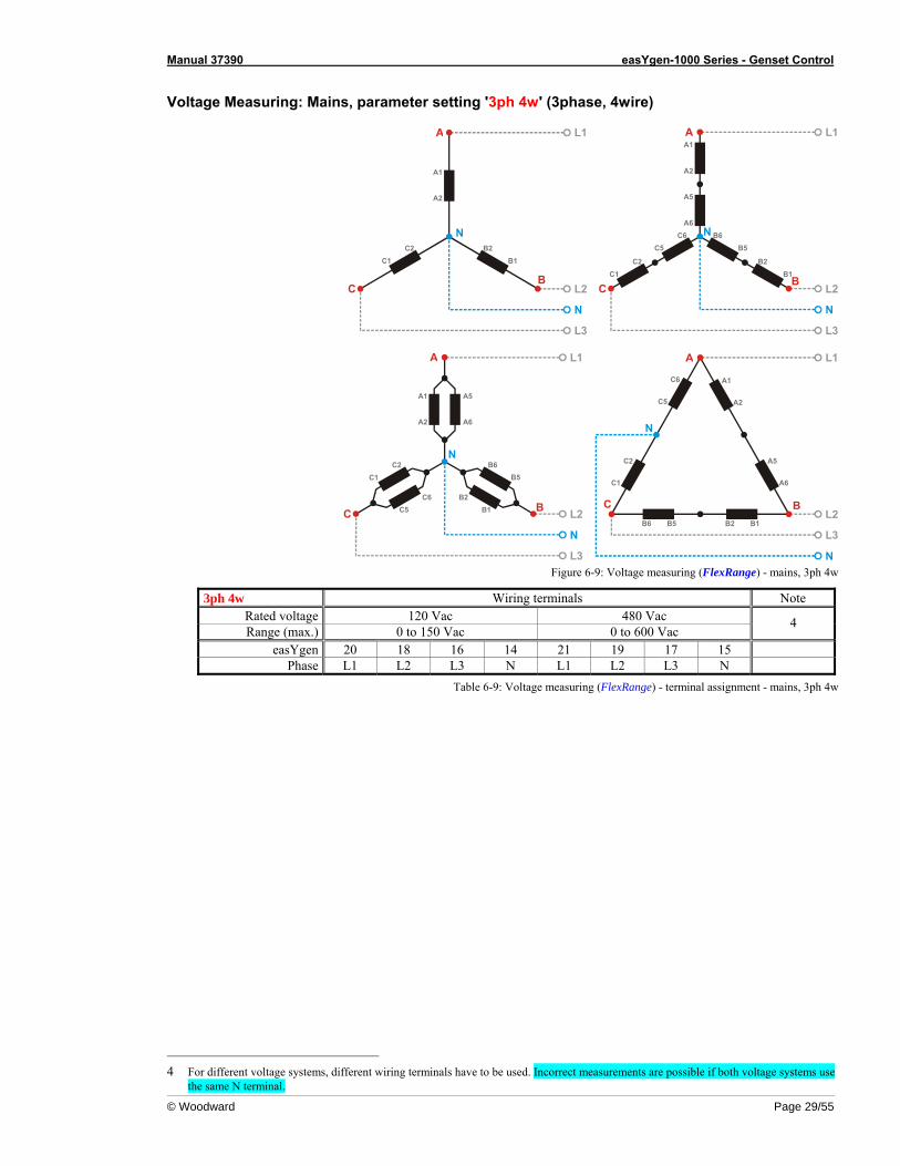
Voltage Measuring: Mains, parameter setting '3ph 4w' (3phase, 4wire)
L1
L2
N
L3
N
A1
A2
A
B
B2B1
C
C2C1
L1
L2
N
L3
N
A1
A2
A
B
C6C5
B6B5
A5
A6
B2B1
C
C2C1
L1
L2
N
L3
N
A1
A2
A
B
B6B5
A5
A6
CC6
C5B2
B1
C2C1
L1
L2
L3
N
N
B1B2
C6
C5
A1
A2
B5B6
A
BC
C2
C1
A5
A6
Figure 6-9: Voltage measuring (FlexRange) - mains, 3ph 4w
3ph 4w Wiring terminals Note Rated voltage 120 Vac 480 Vac Range (max.) 0 to 150 Vac 0 to 600 Vac
4
easYgen 20 18 16 14 21 19 17 15 Phase L1 L2 L3 N L1 L2 L3 N
Table 6-9: Voltage measuring (FlexRange) - terminal assignment - mains, 3ph 4w
4 For different voltage systems, different wiring terminals have to be used. Incorrect measurements are possible if both voltage systems use
the same N terminal.
Manual 37390 easYgen-1000 Series - Genset Control
Page 30/55 © Woodward
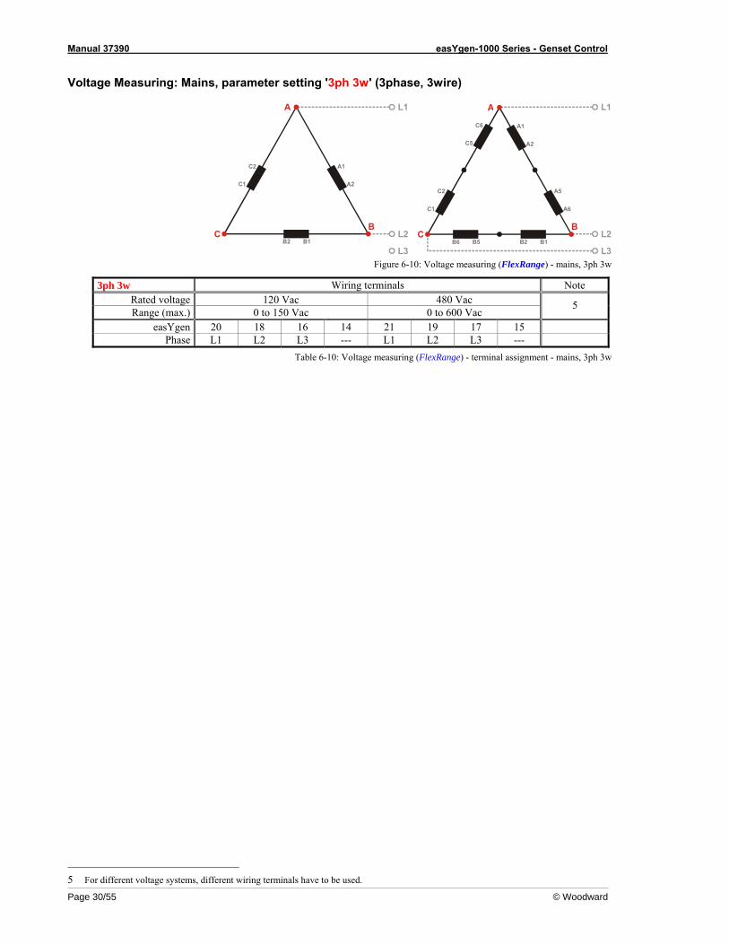
Voltage Measuring: Mains, parameter setting '3ph 3w' (3phase, 3wire)
L1
L2
L3B2
C2
C1
A1
A2
B1
A
BC
L1
L2
L3B1B2
C6
C5
A1
A2
B5B6
A
BC
C2
C1
A5
A6
Figure 6-10: Voltage measuring (FlexRange) - mains, 3ph 3w
3ph 3w Wiring terminals Note Rated voltage 120 Vac 480 Vac Range (max.) 0 to 150 Vac 0 to 600 Vac
5
easYgen 20 18 16 14 21 19 17 15 Phase L1 L2 L3 --- L1 L2 L3 ---
Table 6-10: Voltage measuring (FlexRange) - terminal assignment - mains, 3ph 3w
5 For different voltage systems, different wiring terminals have to be used.
Manual 37390 easYgen-1000 Series - Genset Control
© Woodward Page 31/55
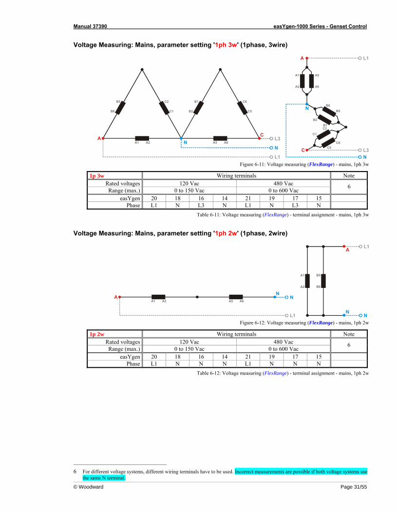
Voltage Measuring: Mains, parameter setting '1ph 3w' (1phase, 3wire)
L3
N
L1
N
B5
B6
C2
C1
A2A1A
B1
B2
C6
C5
A6A5
C
L1
L3N
N
C
A1
A2
A
B6B5
A5
A6
C6C5
B2B1C2
C1
Figure 6-11: Voltage measuring (FlexRange) - mains, 1ph 3w
1p 3w Wiring terminals Note Rated voltages 120 Vac 480 Vac Range (max.) 0 to 150 Vac 0 to 600 Vac
6
easYgen 20 18 16 14 21 19 17 15 Phase L1 N L3 N L1 N L3 N
Table 6-11: Voltage measuring (FlexRange) - terminal assignment - mains, 1ph 3w
Voltage Measuring: Mains, parameter setting '1ph 2w' (1phase, 2wire)
N
L1
NA2A1
AA6A5
L1
NN
B5
B6
A1
A2
A
Figure 6-12: Voltage measuring (FlexRange) - mains, 1ph 2w
1p 2w Wiring terminals Note Rated voltages 120 Vac 480 Vac Range (max.) 0 to 150 Vac 0 to 600 Vac
6
easYgen 20 18 16 14 21 19 17 15 Phase L1 N N N L1 N N N
Table 6-12: Voltage measuring (FlexRange) - terminal assignment - mains, 1ph 2w
6 For different voltage systems, different wiring terminals have to be used. Incorrect measurements are possible if both voltage systems use
the same N terminal.
Manual 37390 easYgen-1000 Series - Genset Control
Page 32/55 © Woodward
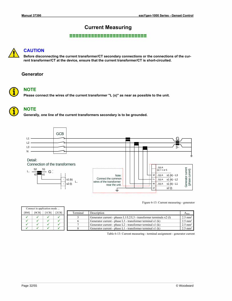
Current Measuring ≡≡≡≡≡≡≡≡≡≡≡≡≡≡≡≡≡≡≡≡≡≡≡≡≡
CAUTION Before disconnecting the current transformer/CT secondary connections or the connections of the cur-rent transformer/CT at the device, ensure that the current transformer/CT is short-circuited.
Generator
NOTE Please connect the wires of the current transformer "L (x)" as near as possible to the unit.
NOTE Generally, one line of the current transformers secondary is to be grounded.
Note:Connect the common
wires of the transformer near the unit.
Detail:Connection of the transformers
S2
s2L..
s1 (k)..
L..s2 (l)..
GS1
s1 67
85
s1 (k) - L1s2 (l)
s1 (k) - L3
L1L2L3N
GCB
s1 (k) - L2
Gene
rato
r cur
rent
(pha
se cu
rrent
)
../{x} A
../{x} A
../{x} A
../{x} A{x} = 1 or 5
G
3~
Figure 6-13: Current measuring - generator
Connect in application mode ... [BM] [0CB] [1CB] [2CB] Terminal Description Amax
5 Generator current - phases L1/L2/L3 - transformer terminals x2 (l) 2.5 mm² 6 Generator current - phase L3 - transformer terminal s1 (k) 2.5 mm² 7 Generator current - phase L2 - transformer terminal s1 (k) 2.5 mm² 8 Generator current - phase L1 - transformer terminal s1 (k) 2.5 mm²
Table 6-13: Current measuring - terminal assignment - generator current
Manual 37390 easYgen-1000 Series - Genset Control
© Woodward Page 33/55
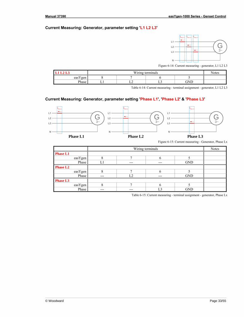
Current Measuring: Generator, parameter setting 'L1 L2 L3'
L1
L2
N
L3 3~G
IGen L3IGen L2IGen L1
Figure 6-14: Current measuring - generator, L1 L2 L3
L1 L2 L3 Wiring terminals Notes easYgen 8 7 6 5
Phase L1 L2 L3 GND Table 6-14: Current measuring - terminal assignment - generator, L1 L2 L3
Current Measuring: Generator, parameter setting 'Phase L1', 'Phase L2' & 'Phase L3'
L1
L2
N
L3 3~G
IGen L1
L1
L2
N
L3 3~G
IGen L2
L1
L2
N
L3 3~G
IGen L3
Phase L1 Phase L2 Phase L3
Figure 6-15: Current measuring - Generator, Phase Lx
Wiring terminals Notes Phase L1
easYgen 8 7 6 5 Phase L1 --- --- GND
Phase L2 easYgen 8 7 6 5
Phase --- L2 --- GND Phase L3
easYgen 8 7 6 5 Phase --- --- L3 GND
Table 6-15: Current measuring - terminal assignment - generator, Phase Lx

Manual 37390 easYgen-1000 Series - Genset Control
Page 34/55 © Woodward
Mains Current ({2oc} Only)
NOTE Generally, one line of the current transformers secondary is to be grounded.
Detail:Connection of the transformers
S2
s2L..
s1 (k)..
L..s2 (l)..
S1
s1
21
s1 (k) - L1s2 (l)
Main
scu
rrent
../{x} A
../{x} A{x} = 1 or 5
L1L2L3N
MCB
Figure 6-16: Current measuring - mains current
Connect in application mode ... [BM] [0CB] [1CB] [2CB] Terminal Description Amax --- --- --- 1 Mains current - phase L1 - transformer terminal s2 (l) 2.5 mm²--- --- --- 2 Mains current - phase L1 - transformer terminal s1 (k) 2.5 mm²
Table 6-16: Current measuring - terminal assignment - mains current
Current Measuring: Mains, parameter setting 'Phase L1', 'Phase L2' & 'Phase L3'
L1
L2
N
L3
IMains L1
L1
L2
N
L3
IMains L2
L1
L2
N
L3
IMains L3
Phase L1 Phase L2 Phase L3
Figure 6-17: Current measuring - generator, Phase Lx
Wiring terminals Notes Phase L1
easYgen 1 2 Phase GND L1
Phase L2 easYgen 1 2
Phase GND L2 Phase L3
easYgen 1 2 Phase GND L3
Table 6-17: current measuring - terminal assignment - generator, Phase Lx
Manual 37390 easYgen-1000 Series - Genset Control
© Woodward Page 35/55
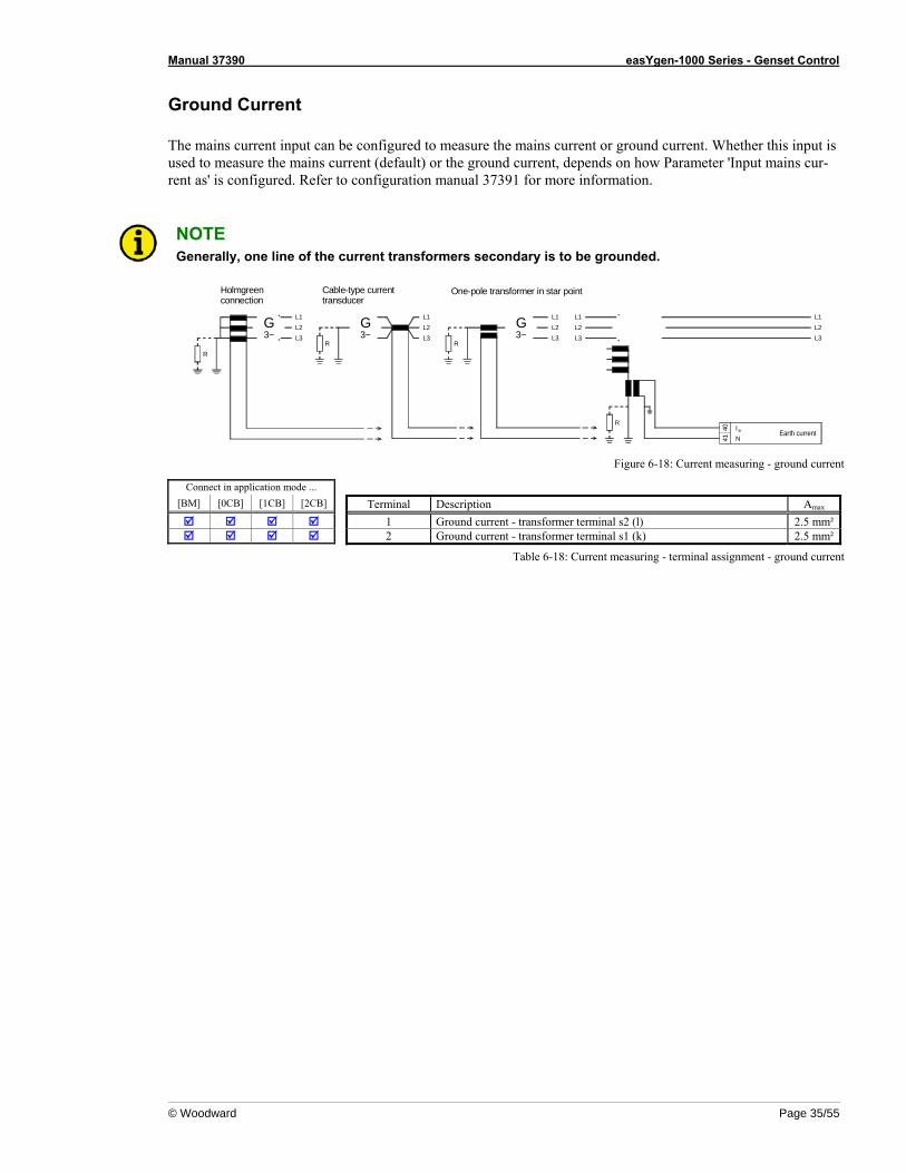
Ground Current The mains current input can be configured to measure the mains current or ground current. Whether this input is used to measure the mains current (default) or the ground current, depends on how Parameter 'Input mains cur-rent as' is configured. Refer to configuration manual 37391 for more information.
NOTE Generally, one line of the current transformers secondary is to be grounded.
N
4041
L1L2L3
Earth currentI e
G3~
L2L3
L1G3~
L2L3
L1L2L3
L1
Holmgreenconnection
Cable-type currenttransducer
G3~
L2L3
L1
R R
R
One-pole transformer in star point
R
Figure 6-18: Current measuring - ground current
Connect in application mode ... [BM] [0CB] [1CB] [2CB] Terminal Description Amax
1 Ground current - transformer terminal s2 (l) 2.5 mm² 2 Ground current - transformer terminal s1 (k) 2.5 mm²
Table 6-18: Current measuring - terminal assignment - ground current
Manual 37390 easYgen-1000 Series - Genset Control
Page 36/55 © Woodward
Power Measuring ≡≡≡≡≡≡≡≡≡≡≡≡≡≡≡≡≡≡≡≡≡≡≡≡≡
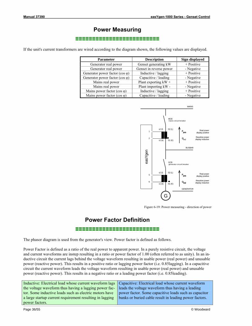
If the unit's current transformers are wired according to the diagram shown, the following values are displayed.
Parameter Description Sign displayed Generator real power Genset generating kW + Positive Generator real power Genset in reverse power - Negative
Generator power factor (cos φ) Inductive / lagging + Positive Generator power factor (cos φ) Capacitive / leading - Negative
Mains real power Plant exporting kW + + Positive Mains real power Plant importing kW - - Negative
Mains power factor (cos φ) Inductive / lagging + Positive Mains power factor (cos φ) Capacitive / leading - Negative
S1 (K)
S2 (L)
S2 (L)
S1 (K)
Real powerdisplay positive
Reacitive powerdisplay inductive
Real powerdisplay positive
Reacitive powerdisplay inductive
GCBgenerator circuit breaker
MCBmains circuit breaker
easY
gen
6
5
s1 (k)
G
s2 (l)
2
1
s1 (k)
s2 (l)
pospos
GENERATOR
indindQQ
PP
pospos
indQQ
PP
BUSBAR
MAINS
Figure 6-19: Power measuring - direction of power
Power Factor Definition ≡≡≡≡≡≡≡≡≡≡≡≡≡≡≡≡≡≡≡≡≡≡≡≡≡
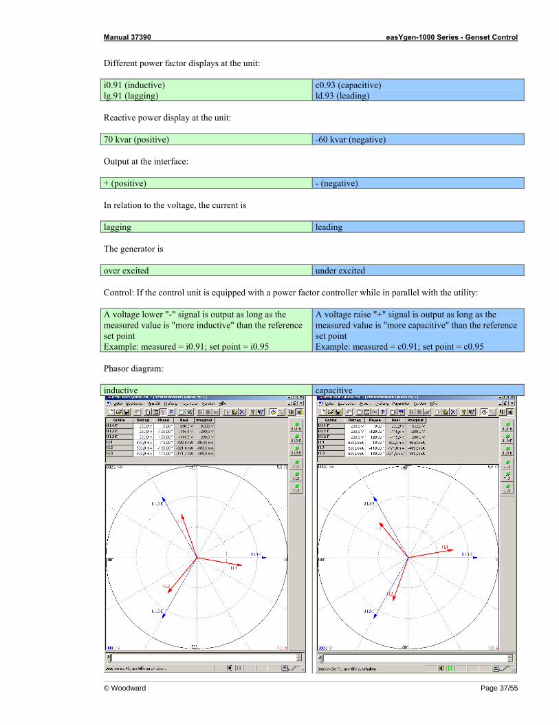
The phasor diagram is used from the generator's view. Power factor is defined as follows. Power Factor is defined as a ratio of the real power to apparent power. In a purely resistive circuit, the voltage and current waveforms are instep resulting in a ratio or power factor of 1.00 (often referred to as unity). In an in-ductive circuit the current lags behind the voltage waveform resulting in usable power (real power) and unusable power (reactive power). This results in a positive ratio or lagging power factor (i.e. 0.85lagging). In a capacitive circuit the current waveform leads the voltage waveform resulting in usable power (real power) and unusable power (reactive power). This results in a negative ratio or a leading power factor (i.e. 0.85leading). Inductive: Electrical load whose current waveform lags the voltage waveform thus having a lagging power fac-tor. Some inductive loads such as electric motors have a large startup current requirement resulting in lagging power factors.
Capacitive: Electrical load whose current waveform leads the voltage waveform thus having a leading power factor. Some capacitive loads such as capacitor banks or buried cable result in leading power factors.
Manual 37390 easYgen-1000 Series - Genset Control
© Woodward Page 37/55
Different power factor displays at the unit: i0.91 (inductive) lg.91 (lagging)
c0.93 (capacitive) ld.93 (leading)
Reactive power display at the unit: 70 kvar (positive) -60 kvar (negative) Output at the interface: + (positive) - (negative) In relation to the voltage, the current is lagging leading The generator is over excited under excited Control: If the control unit is equipped with a power factor controller while in parallel with the utility: A voltage lower "-" signal is output as long as the measured value is "more inductive" than the reference set point Example: measured = i0.91; set point = i0.95
A voltage raise "+" signal is output as long as the measured value is "more capacitive" than the reference set point Example: measured = c0.91; set point = c0.95
Phasor diagram: inductive capacitive
Manual 37390 easYgen-1000 Series - Genset Control
Page 38/55 © Woodward
Pickup ≡≡≡≡≡≡≡≡≡≡≡≡≡≡≡≡≡≡≡≡≡≡≡≡≡
Sensor
toPickup
input
Rotating shaft
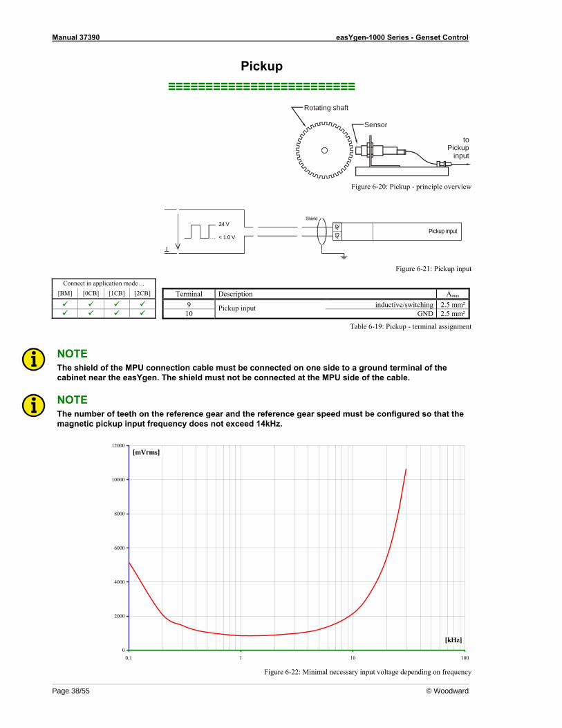
Figure 6-20: Pickup - principle overview
< 1.0 V
24 VPickup input42
43
Shield
Figure 6-21: Pickup input
Connect in application mode ... [BM] [0CB] [1CB] [2CB] Terminal Description Amax
9 inductive/switching 2.5 mm² 10
Pickup input GND 2.5 mm²
Table 6-19: Pickup - terminal assignment
NOTE The shield of the MPU connection cable must be connected on one side to a ground terminal of the cabinet near the easYgen. The shield must not be connected at the MPU side of the cable.
NOTE The number of teeth on the reference gear and the reference gear speed must be configured so that the magnetic pickup input frequency does not exceed 14kHz.
0
2000
4000
6000
8000
10000
12000
0,1 1 10 100
[mVrms]
[kHz]
Figure 6-22: Minimal necessary input voltage depending on frequency
Manual 37390 easYgen-1000 Series - Genset Control
© Woodward Page 39/55
Discrete Inputs ≡≡≡≡≡≡≡≡≡≡≡≡≡≡≡≡≡≡≡≡≡≡≡≡≡
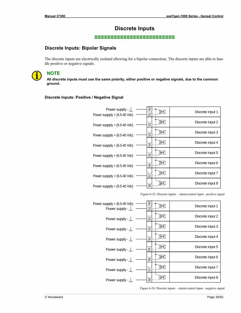
Discrete Inputs: Bipolar Signals The discrete inputs are electrically isolated allowing for a bipolar connection. The discrete inputs are able to han-dle positive or negative signals.
NOTE All discrete inputs must use the same polarity, either positive or negative signals, due to the common ground.
Discrete Inputs: Positive / Negative Signal
5152
Discrete input 150
Power suppply + (6.5-40 Vdc)
Discrete input 2
Discrete input 3
53
Discrete input 4
54Discrete input 5
55
Discrete input 6
56
Discrete input 7
57
Discrete input 8
58
Power supply -
Power suppply + (6.5-40 Vdc)
Power suppply + (6.5-40 Vdc)
Power suppply + (6.5-40 Vdc)
Power suppply + (6.5-40 Vdc)
Power suppply + (6.5-40 Vdc)
Power suppply + (6.5-40 Vdc)
Power suppply + (6.5-40 Vdc)
Figure 6-23: Discrete inputs - alarm/control input - positive signal
5152
Discrete input 150Power suppply + (6.5-40 Vdc)
Discrete input 2
Discrete input 3
53
Discrete input 4
54
Discrete input 5
55
Discrete input 6
56
Discrete input 7
57
Discrete input 8
58
Power supply -
Power supply -
Power supply -
Power supply -
Power supply -
Power supply -
Power supply -
Power supply -
Figure 6-24: Discrete inputs - alarm/control input - negative signal
Manual 37390 easYgen-1000 Series - Genset Control
Page 40/55 © Woodward
Connect in application mode ...
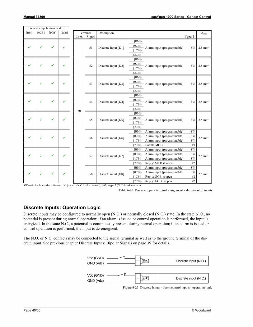
[BM] [0CB] [1CB] [2CB] Terminal Description Amax Com. Signal Type
[BM] - [0CB] - [1CB] -
51 Discrete input [D1]
[2CB] -
Alarm input (programmable) SW 2.5 mm²
[BM] - [0CB] - [1CB] -
52 Discrete input [D2]
[2CB] -
Alarm input (programmable) SW 2.5 mm²
[BM] - [0CB] - [1CB] -
53 Discrete input [D3]
[2CB] -
Alarm input (programmable) SW 2.5 mm²
[BM] - [0CB] - [1CB] -
54 Discrete input [D4]
[2CB] -
Alarm input (programmable) SW 2.5 mm²
[BM] - [0CB] - [1CB] -
55 Discrete input [D5]
[2CB] -
Alarm input (programmable) SW 2.5 mm²
[BM] - Alarm input (programmable) SW [0CB] - Alarm input (programmable) SW [1CB] - Alarm input (programmable) SW
56 Discrete input [D6]
[2CB] - Enable MCB #1
2.5 mm²
[BM] - Alarm input (programmable) SW [0CB] - Alarm input (programmable) SW [1CB] - Alarm input (programmable) SW
57 Discrete input [D7]
[2CB] - Reply: MCB is open #2
2.5 mm²
[BM] - Alarm input (programmable) SW [0CB] - Alarm input (programmable) SW [1CB] - Reply: GCB is open #2
50
58 Discrete input [D8]
[2CB] - Reply: GCB is open #2
2.5 mm²
SW-switchable via the software, [#1]-type 1 (N.O./make contact), [#2] -type 2 (N.C./break contact)
Table 6-20: Discrete input - terminal assignment - alarm/control inputs
Discrete Inputs: Operation Logic Discrete inputs may be configured to normally open (N.O.) or normally closed (N.C.) state. In the state N.O., no potential is present during normal operation; if an alarm is issued or control operation is performed, the input is energized. In the state N.C., a potential is continuously present during normal operation; if an alarm is issued or control operation is performed, the input is de-energized. The N.O. or N.C. contacts may be connected to the signal terminal as well as to the ground terminal of the dis-crete input. See previous chapter Discrete Inputs: Bipolar Signals on page 39 for details.
Discrete input (N.O.)Vdc (GND)GND (Vdc)
Discrete input (N.C.)Vdc (GND)GND (Vdc)
Figure 6-25: Discrete inputs - alarm/control inputs - operation logic
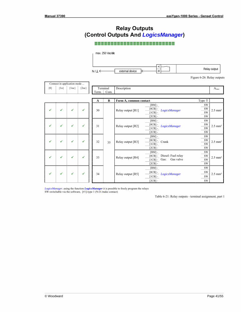
Manual 37390 easYgen-1000 Series - Genset Control
© Woodward Page 41/55
Relay Outputs (Control Outputs And LogicsManager)
≡≡≡≡≡≡≡≡≡≡≡≡≡≡≡≡≡≡≡≡≡≡≡≡≡
AB
Relay outputexternal device
max. 250 Vac/dc
N / Figure 6-26: Relay outputs
Connect in application mode ... {0} {1o} {1oc} {2oc} Terminal Description Amax
Term. Com. A B Form A, common contact Type
[BM] - SW [0CB] - SW [1CB] - SW
30 Relay output [R1]
[2CB] -
LogicsManager
SW
2.5 mm²
[BM] - SW [0CB] - SW [1CB] - SW
31 Relay output [R2]
[2CB] -
LogicsManager
SW
2.5 mm²
[BM] - SW [0CB] - SW [1CB] - SW
32 Relay output [R3]
[2CB] -
Crank
SW
2.5 mm²
[BM] - SW [0CB] - SW [1CB] - SW
33 Relay output [R4]
[2CB] -
Diesel: Fuel relay Gas: Gas valve
SW
2.5 mm²
[BM] - SW [0CB] - SW [1CB] - SW
34
35
Relay output [R5]
[2CB] -
LogicsManager
SW
2.5 mm²
LogicsManager..using the function LogicsManager it is possible to freely program the relays SW-switchable via the software, [#1]-type 1 (N.O./make contact)
Table 6-21: Relay outputs - terminal assignment, part 1

Manual 37390 easYgen-1000 Series - Genset Control
Page 42/55 © Woodward
Connect in application mode ...
{0} {1o} {1oc} {2oc} Terminal Description Amax Term. Com. A B Form A, separated contacts Type
[BM] - SW [0CB] - SW [1CB] - SW
36 37 Relay output [R6]
[2CB] -
LogicsManager
SW
2.5 mm²
[BM] - LogicsManager SW [0CB] - Command: open GCB #1 [1CB] - Command: open GCB #1
38 39 Relay output [R7]
[2CB] - Command: open GCB #1
2.5 mm²
[BM] - LogicsManager SW [0CB] - LogicsManager SW [1CB] - LogicsManager SW
40 41 Relay output [R8]
[2CB] - Command: close MCB #1
2.5 mm²
[BM] - LogicsManager SW [0CB] - LogicsManager SW [1CB] - LogicsManager SW
42 43 Relay output [R9]
[2CB] - Command: open MCB #1
2.5 mm²
[BM] - LogicsManager SW [0CB] - LogicsManager SW [1CB] - Command: close GCB #1
44 45 Relay output [R10]
[2CB] - Command: close GCB #1
2.5 mm²
[BM] - [0CB] - [1CB] -
46 47 Relay output [R11]
[2CB] -
Ready for operation LogicsManager (closed in normal operation state)
#1 2.5 mm²
LogicsManager..using the function LogicsManager it is possible to freely program the relays SW-switchable via the software, [#1]-type 1 (N.O./make contact)
Table 6-22: Relay outputs - terminal assignment, part 1
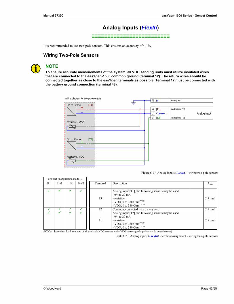
Manual 37390 easYgen-1000 Series - Genset Control
© Woodward Page 43/55
Analog Inputs (FlexIn) ≡≡≡≡≡≡≡≡≡≡≡≡≡≡≡≡≡≡≡≡≡≡≡≡≡
It is recommended to use two-pole sensors. This ensures an accuracy of ≤ 1%.
Wiring Two-Pole Sensors
NOTE To ensure accurate measurements of the system, all VDO sending units must utilize insulated wires that are connected to the easYgen-1500 common ground (terminal 12). The return wires should be connected together as close to the easYgen terminals as possible. Terminal 12 must be connected with the battery ground connection (terminal 48).
1113
12 Analog inputAnalog input [T1]
Analog input [T2]
[T1]
[T2]Resistive / VDO
Resistive / VDO
[T1]
[T2]
48 B -Wiring diagram for two-pole sensors
Common
0/4 to 20 mA
0/4 to 20 mA
Battery zero
Figure 6-27: Analog inputs (FlexIn) - wiring two-pole sensors
Connect in application mode ... {0} {1o} {1oc} {2oc} Terminal Description Amax
13
Analog input [T1], the following sensors may be used: - 0/4 to 20 mA - resistive - VDO, 0 to 180 Ohm#VDO - VDO, 0 to 380 Ohm#VDO
2.5 mm²
12 Common, connected with battery zero 2.5 mm²
11
Analog input [T2], the following sensors may be used: - 0/4 to 20 mA - resistive - VDO, 0 to 180 Ohm#VDO - VDO, 0 to 380 Ohm#VDO
2.5 mm²
#VDO - please download a catalog of all available VDO sensors at the VDO homepage (http://www.vdo.com/siemens)
Table 6-23: Analog inputs (FlexIn) - terminal assignment - wiring two-pole sensors
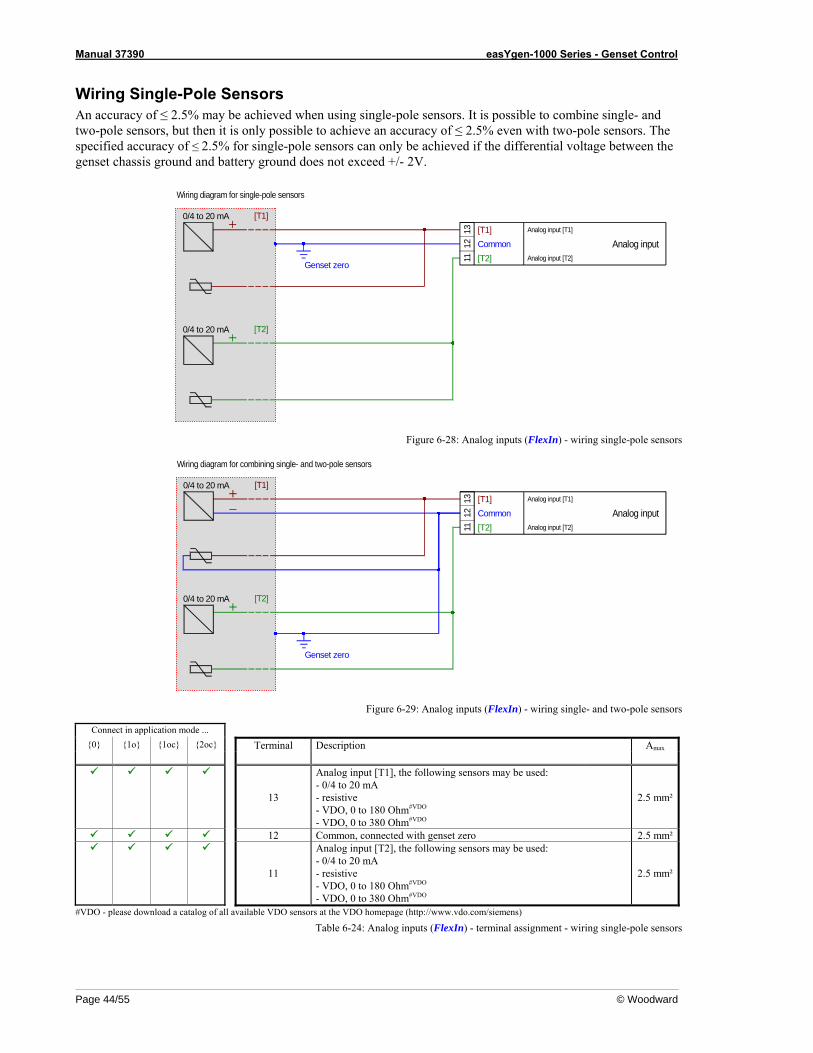
Manual 37390 easYgen-1000 Series - Genset Control
Page 44/55 © Woodward
Wiring Single-Pole Sensors An accuracy of ≤ 2.5% may be achieved when using single-pole sensors. It is possible to combine single- and two-pole sensors, but then it is only possible to achieve an accuracy of ≤ 2.5% even with two-pole sensors. The specified accuracy of ≤ 2.5% for single-pole sensors can only be achieved if the differential voltage between the genset chassis ground and battery ground does not exceed +/- 2V.
1113
12
[T1]
[T2]
[T1]
[T2]
Wiring diagram for single-pole sensors
Common
0/4 to 20 mA
0/4 to 20 mA
Analog input [T1]
Analog input [T2]
Analog input
Genset zero
Figure 6-28: Analog inputs (FlexIn) - wiring single-pole sensors
1113
12
[T1]
[T2]
[T1]
[T2]
Common
0/4 to 20 mA
0/4 to 20 mA
Analog input [T1]
Analog input [T2]
Analog input
Wiring diagram for combining single- and two-pole sensors
Genset zero
Figure 6-29: Analog inputs (FlexIn) - wiring single- and two-pole sensors
Connect in application mode ... {0} {1o} {1oc} {2oc} Terminal Description Amax
13
Analog input [T1], the following sensors may be used: - 0/4 to 20 mA - resistive - VDO, 0 to 180 Ohm#VDO - VDO, 0 to 380 Ohm#VDO
2.5 mm²
12 Common, connected with genset zero 2.5 mm²
11
Analog input [T2], the following sensors may be used: - 0/4 to 20 mA - resistive - VDO, 0 to 180 Ohm#VDO - VDO, 0 to 380 Ohm#VDO
2.5 mm²
#VDO - please download a catalog of all available VDO sensors at the VDO homepage (http://www.vdo.com/siemens)
Table 6-24: Analog inputs (FlexIn) - terminal assignment - wiring single-pole sensors
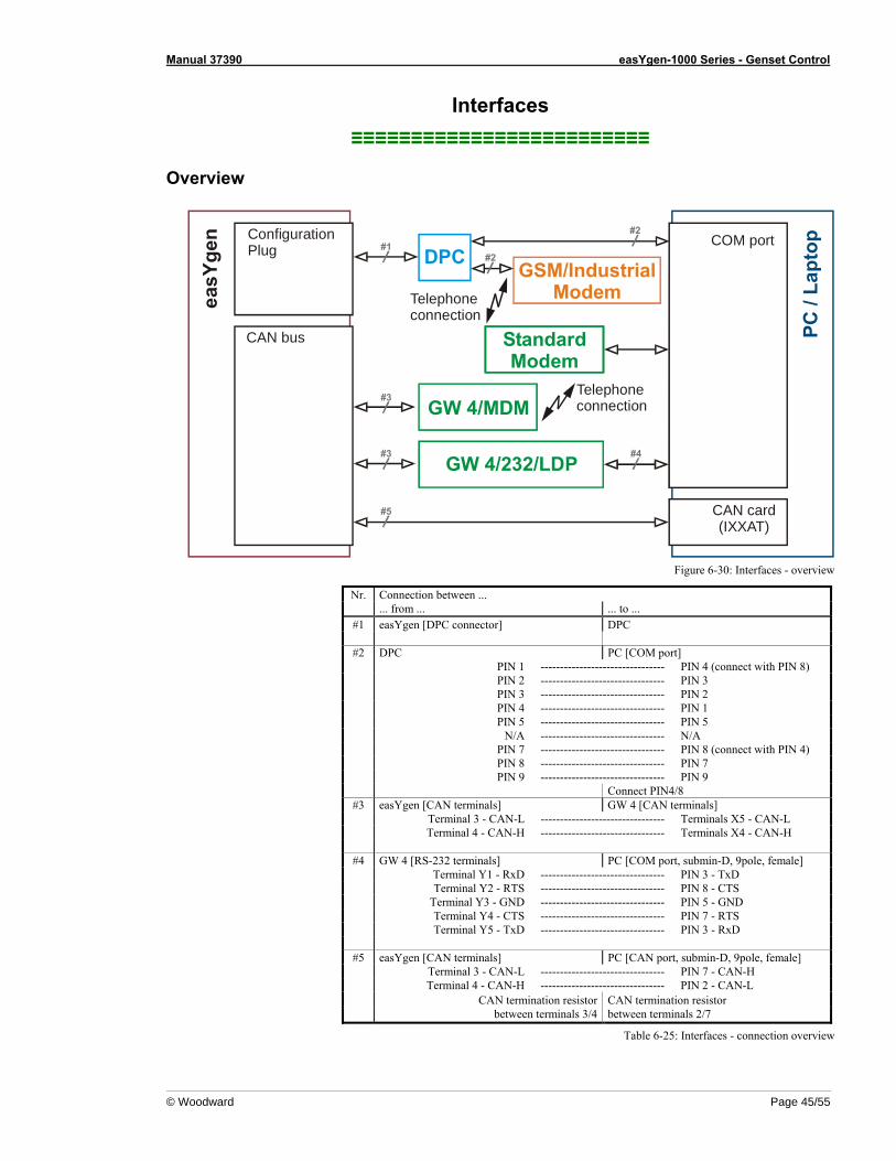
Manual 37390 easYgen-1000 Series - Genset Control
© Woodward Page 45/55
Interfaces ≡≡≡≡≡≡≡≡≡≡≡≡≡≡≡≡≡≡≡≡≡≡≡≡≡
Overview
PC /
Lapt
op#1#2
#3 #4
#5
#3
StandardModem
#2
Telephoneconnection
COM port
CAN card(IXXAT)
ConfigurationPlug
CAN bus
Telephoneconnection
GSM/IndustrialModemea
sYge
n
DPC
GW 4/232/LDP
GW 4/MDM
Figure 6-30: Interfaces - overview
Nr. Connection between ... ... from ... ... to ... #1 easYgen [DPC connector] DPC #2 DPC PC [COM port] PIN 1 -------------------------------- PIN 4 (connect with PIN 8) PIN 2 -------------------------------- PIN 3 PIN 3 -------------------------------- PIN 2 PIN 4 -------------------------------- PIN 1 PIN 5 -------------------------------- PIN 5 N/A -------------------------------- N/A PIN 7 -------------------------------- PIN 8 (connect with PIN 4) PIN 8 -------------------------------- PIN 7 PIN 9 -------------------------------- PIN 9 Connect PIN4/8 #3 easYgen [CAN terminals] GW 4 [CAN terminals] Terminal 3 - CAN-L -------------------------------- Terminals X5 - CAN-L Terminal 4 - CAN-H -------------------------------- Terminals X4 - CAN-H #4 GW 4 [RS-232 terminals] PC [COM port, submin-D, 9pole, female] Terminal Y1 - RxD -------------------------------- PIN 3 - TxD Terminal Y2 - RTS -------------------------------- PIN 8 - CTS Terminal Y3 - GND -------------------------------- PIN 5 - GND Terminal Y4 - CTS -------------------------------- PIN 7 - RTS Terminal Y5 - TxD -------------------------------- PIN 3 - RxD #5 easYgen [CAN terminals] PC [CAN port, submin-D, 9pole, female] Terminal 3 - CAN-L -------------------------------- PIN 7 - CAN-H Terminal 4 - CAN-H -------------------------------- PIN 2 - CAN-L
CAN termination resistorbetween terminals 3/4
CAN termination resistor between terminals 2/7
Table 6-25: Interfaces - connection overview
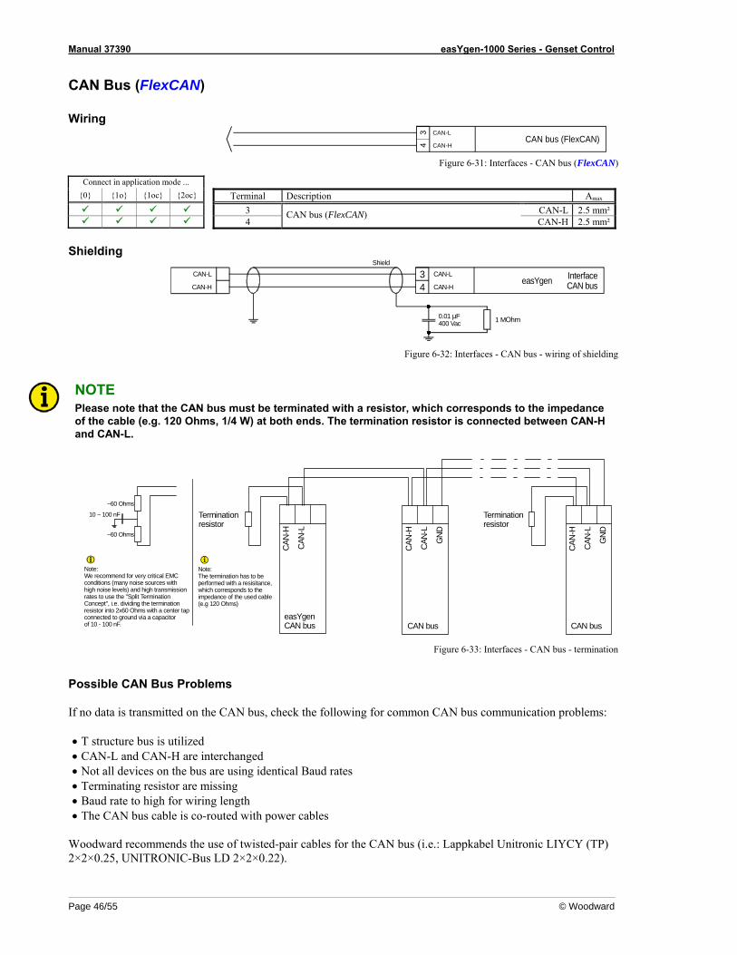
Manual 37390 easYgen-1000 Series - Genset Control
Page 46/55 © Woodward
CAN Bus (FlexCAN)
Wiring CAN bus (FlexCAN)
CAN-L
4 CAN-H
3
Figure 6-31: Interfaces - CAN bus (FlexCAN)
Connect in application mode ... {0} {1o} {1oc} {2oc} Terminal Description Amax
3 CAN-L 2.5 mm² 4
CAN bus (FlexCAN) CAN-H 2.5 mm²
Shielding
34
CAN-L
CAN-H
1 MOhm0.01 µF400 Vac
CAN-L
CAN-H
Shield
InterfaceCAN buseasYgen
Figure 6-32: Interfaces - CAN bus - wiring of shielding
NOTE Please note that the CAN bus must be terminated with a resistor, which corresponds to the impedance of the cable (e.g. 120 Ohms, 1/4 W) at both ends. The termination resistor is connected between CAN-H and CAN-L.
G
ND
GND
CAN-
L
CAN-
H
CAN-
L
CAN-
H
CAN-
L
CAN-
H
easYgenCAN bus
Terminationresistor
Note:The termination has to be performed with a resisitance,which corresponds to the impedance of the used cable (e.g 120 Ohms)
CAN bus CAN bus
Terminationresistor
10 ~ 100 nF
~60 Ohms
Note:We recommend for very critical EMCconditions (many noise sources withhigh noise levels) and high transmissionrates to use the "Split Termination Concept", i.e. dividing the terminationresistor into 2x60 Ohms with a center tapconnected to ground via a capacitor of 10 - 100 nF.
~60 Ohms
Figure 6-33: Interfaces - CAN bus - termination
Possible CAN Bus Problems If no data is transmitted on the CAN bus, check the following for common CAN bus communication problems: • T structure bus is utilized • CAN-L and CAN-H are interchanged • Not all devices on the bus are using identical Baud rates • Terminating resistor are missing • Baud rate to high for wiring length • The CAN bus cable is co-routed with power cables
Woodward recommends the use of twisted-pair cables for the CAN bus (i.e.: Lappkabel Unitronic LIYCY (TP) 2×2×0.25, UNITRONIC-Bus LD 2×2×0.22).
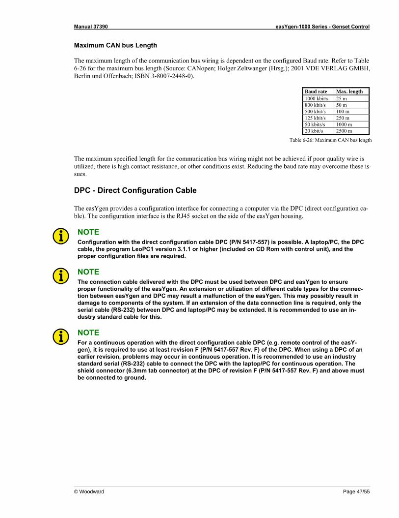
Manual 37390 easYgen-1000 Series - Genset Control
© Woodward Page 47/55
Maximum CAN bus Length The maximum length of the communication bus wiring is dependent on the configured Baud rate. Refer to Table 6-26 for the maximum bus length (Source: CANopen; Holger Zeltwanger (Hrsg.); 2001 VDE VERLAG GMBH, Berlin und Offenbach; ISBN 3-8007-2448-0).
Baud rate Max. length 1000 kbit/s 25 m 800 kbit/s 50 m 500 kbit/s 100 m 125 kbit/s 250 m 50 kbits/s 1000 m 20 kbit/s 2500 m
Table 6-26: Maximum CAN bus length
The maximum specified length for the communication bus wiring might not be achieved if poor quality wire is utilized, there is high contact resistance, or other conditions exist. Reducing the baud rate may overcome these is-sues.
DPC - Direct Configuration Cable The easYgen provides a configuration interface for connecting a computer via the DPC (direct configuration ca-ble). The configuration interface is the RJ45 socket on the side of the easYgen housing.
NOTE Configuration with the direct configuration cable DPC (P/N 5417-557) is possible. A laptop/PC, the DPC cable, the program LeoPC1 version 3.1.1 or higher (included on CD Rom with control unit), and the proper configuration files are required.
NOTE The connection cable delivered with the DPC must be used between DPC and easYgen to ensure proper functionality of the easYgen. An extension or utilization of different cable types for the connec-tion between easYgen and DPC may result a malfunction of the easYgen. This may possibly result in damage to components of the system. If an extension of the data connection line is required, only the serial cable (RS-232) between DPC and laptop/PC may be extended. It is recommended to use an in-dustry standard cable for this.
NOTE For a continuous operation with the direct configuration cable DPC (e.g. remote control of the easY-gen), it is required to use at least revision F (P/N 5417-557 Rev. F) of the DPC. When using a DPC of an earlier revision, problems may occur in continuous operation. It is recommended to use an industry standard serial (RS-232) cable to connect the DPC with the laptop/PC for continuous operation. The shield connector (6.3mm tab connector) at the DPC of revision F (P/N 5417-557 Rev. F) and above must be connected to ground.
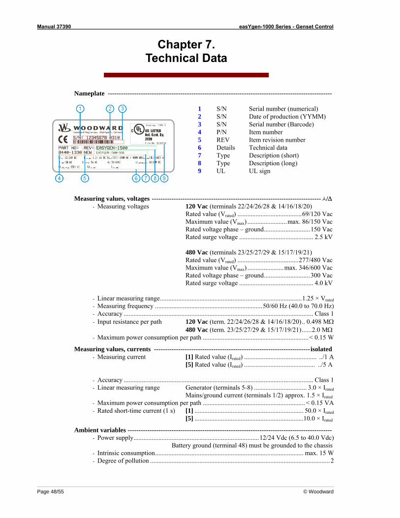
Manual 37390 easYgen-1000 Series - Genset Control
Page 48/55 © Woodward
Chapter 7. Technical Data
Nameplate ------------------------------------------------------------------------------------------------------
1 S/N Serial number (numerical) 2 S/N Date of production (YYMM) 3 S/N Serial number (Barcode) 4 P/N Item number 5 REV Item revision number 6 Details Technical data 7 Type Description (short) 8 Type Description (long) 9 UL UL sign
Measuring values, voltages ----------------------------------------------------------------------------- /Δ - Measuring voltages 120 Vac (terminals 22/24/26/28 & 14/16/18/20)
Rated value (Vrated) .......................................69/120 Vac Maximum value (Vmax) ........................max. 86/150 Vac Rated voltage phase – ground............................150 Vac Rated surge voltage ............................................. 2.5 kV 480 Vac (terminals 23/25/27/29 & 15/17/19/21) Rated value (Vrated) .....................................277/480 Vac Maximum value (Vmax) ......................max. 346/600 Vac Rated voltage phase – ground............................300 Vac Rated surge voltage ............................................. 4.0 kV
- Linear measuring range......................................................................................1.25 × Vrated - Measuring frequency .................................................................50/60 Hz (40.0 to 70.0 Hz) - Accuracy ................................................................................................................... Class 1 - Input resistance per path 120 Vac (term. 22/24/26/28 & 14/16/18/20).. 0.498 MΩ
480 Vac (term. 23/25/27/29 & 15/17/19/21)......2.0 MΩ - Maximum power consumption per path ................................................................< 0.15 W
Measuring values, currents -----------------------------------------------------------------------isolated - Measuring current [1] Rated value (Irated) ............................................ ../1 A
[5] Rated value (Irated) ........................................... ../5 A
- Accuracy ................................................................................................................... Class 1 - Linear measuring range Generator (terminals 5-8) ................................ 3.0 × Irated
Mains/ground current (terminals 1/2) approx. 1.5 × Irated - Maximum power consumption per path .............................................................. < 0.15 VA - Rated short-time current (1 s) [1] .................................................................. 50.0 × Irated
[5] ..................................................................10.0 × Irated
Ambient variables --------------------------------------------------------------------------------------------- - Power supply............................................................................12/24 Vdc (6.5 to 40.0 Vdc)
Battery ground (terminal 48) must be grounded to the chassis - Intrinsic consumption.......................................................................................... max. 15 W - Degree of pollution ............................................................................................................. 2

Manual 37390 easYgen-1000 Series - Genset Control
© Woodward Page 49/55
Discrete inputs ---------------------------------------------------------------------------------------isolated - Input range (VCont, digital input) .............................. Rated voltage 12/24 Vdc (6.5 to 40.0 Vdc) - Input resistance............................................................................................. approx. 6.7 kΩ
Relay outputs ---------------------------------------------------------------------------------potential free - Contact material........................................................................................................ AgCdO - General purpose (GP) (VCont, relay output)
AC................................................... 2.00 Aac@250 Vac DC.....................................................2.00 Adc@24 Vdc 0.36 Adc@125 Vdc 0.18 Adc@250 Vdc
- Pilot duty (PD) (VCont, relay output) AC.......................................................................... B300 DC.....................................................1.00 Adc@24 Vdc 0.22 Adc@125 Vdc 0.10 Adc@250 Vdc
Analog inputs ------------------------------------------------------------------------------ freely scaleable - Resolution....................................................................................................................10 Bit - 0/4 to 20 mA input................................................................................... internal load 50 Ω - 0 to 180/380 Ω input.......................................................................... load current ≤ 2.3 mA - Accuracy solely two-pole sensors ........................................... ≤ 1%
single-pole sensors ...............................................≤ 2.5%
Magnetic Pickup Input ----------------------------------------------------------capacitively decoupled - Input impedance .................................................................................... min. approx. 17 kΩ - Input voltage.......................................................................................... refer to Figure 6-22
Manual 37390 easYgen-1000 Series - Genset Control
Page 50/55 © Woodward
Interface -------------------------------------------------------------------------------------------------------- Service interface
- Version......................................................................................................................RS-232 - Signal level....................................................................................................................... 5V
Level conversion and insulation by using DPC (P/N 5417-557) CAN bus interface ................................................................................................ isolated
- Insulation voltage................................................................................................. 1,500 Vdc - Version................................................................................................................... CAN bus - Internal line termination...................................................................................Not available
Battery ----------------------------------------------------------------------------------------------------------- - Type ............................................................................................................................. NiCd - Durability (at operation without power supply)............................................approx. 5 years - Battery field replacement ...................................................................................not possible
Housing ----------------------------------------------------------------------------------------------------------
- Type ........................................................................................... APRANORM DIN 43 700 - Dimensions (W × H × D)...................................................................... 192 × 144 × 64 mm - Front cutout (W × H) ...............................................................186 [+1.1] × 138 [+1.0] mm - Wiring ................................................................................... screw-plug-terminals 2.5 mm² - Recommended locked torque...........................................................4 inch pounds / 0.5 Nm
use 60/75 °C copper wire only use class 1 wire only or equivalent
- Weight.............................................................................................................approx. 800 g
Protection -------------------------------------------------------------------------------------------------------
- Protection system ...................................................IP42 from front with proper installation IP54 from front with gasket (gasket: P/N 8923-1043) IP20 from back
- Front folio ................................................................................................. insulating surface - EMC test (CE)................................................ tested according to applicable EN guidelines - Listings.........................................................CE marking; UL listing for ordinary locations - Type approval ..................................UL/cUL listed, Ordinary Locations, File No.: 231544
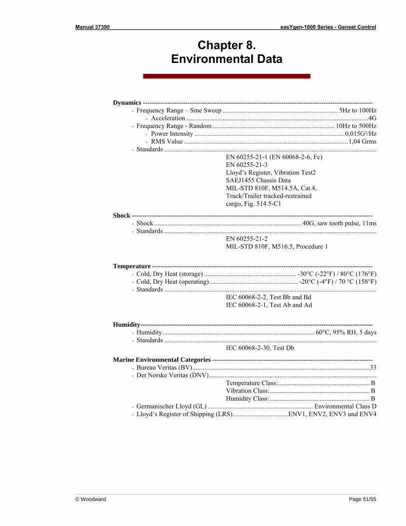
Manual 37390 easYgen-1000 Series - Genset Control
© Woodward Page 51/55
Chapter 8. Environmental Data
Dynamics ------------------------------------------------------------------------------------------------------- - Frequency Range – Sine Sweep ..................................................................... 5Hz to 100Hz
- Acceleration .............................................................................................................4G - Frequency Range - Random ......................................................................... 10Hz to 500Hz
- Power Intensity ..........................................................................................0,015G²/Hz - RMS Value ..................................................................................................1,04 Grms
- Standards ............................................................................................................................... EN 60255-21-1 (EN 60068-2-6, Fc) EN 60255-21-3 Lloyd’s Register, Vibration Test2 SAEJ1455 Chassis Data MIL-STD 810F, M514.5A, Cat.4, Truck/Trailer tracked-restrained cargo, Fig. 514.5-C1
Shock ------------------------------------------------------------------------------------------------------------ - Shock ........................................................................................ 40G, saw tooth pulse, 11ms - Standards ...............................................................................................................................
EN 60255-21-2 MIL-STD 810F, M516.5, Procedure 1
Temperature --------------------------------------------------------------------------------------------------- - Cold, Dry Heat (storage) ....................................................... -30°C (-22°F) / 80°C (176°F) - Cold, Dry Heat (operating)..................................................... -20°C (-4°F) / 70 °C (158°F) - Standards ...............................................................................................................................
IEC 60068-2-2, Test Bb and Bd IEC 60068-2-1, Test Ab and Ad
Humidity-------------------------------------------------------------------------------------------------------- - Humidity........................................................................................... 60°C, 95% RH, 5 days - Standards ...............................................................................................................................
IEC 60068-2-30, Test Db
Marine Environmental Categories ------------------------------------------------------------------------ - Bureau Veritas (BV)..........................................................................................................33 - Det Norske Veritas (DNV)....................................................................................................
Temperature Class:....................................................... B Vibration Class:............................................................ B Humidity Class:............................................................ B
- Germanischer Lloyd (GL) ............................................................... Environmental Class D - Lloyd’s Register of Shipping (LRS).................................ENV1, ENV2, ENV3 und ENV4
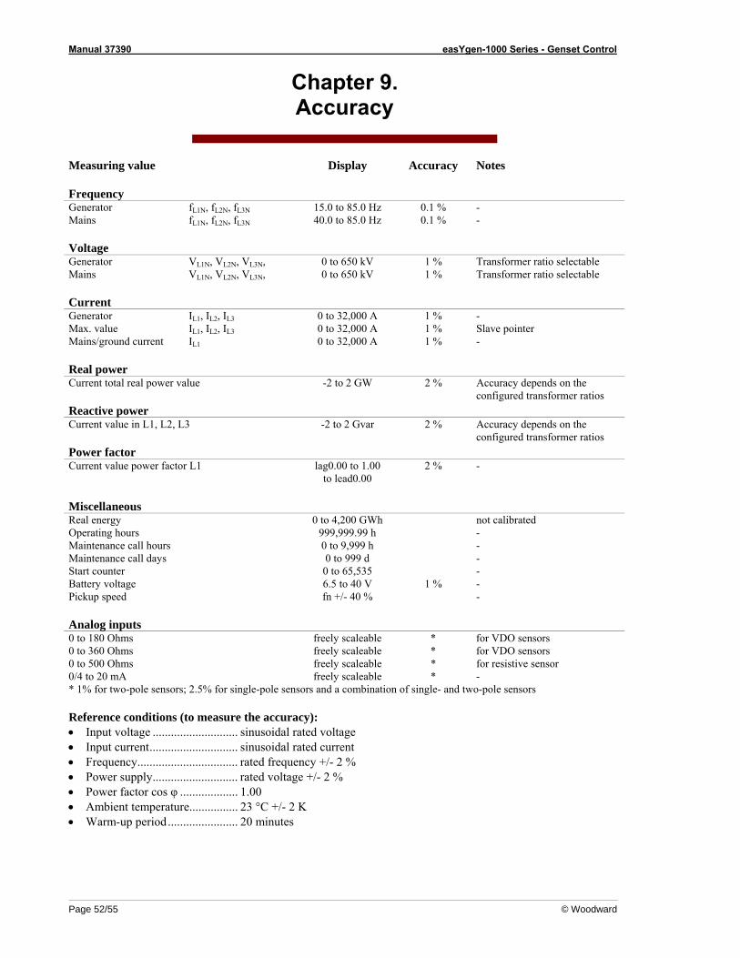
Manual 37390 easYgen-1000 Series - Genset Control
Page 52/55 © Woodward
Chapter 9. Accuracy
Measuring value Display Accuracy Notes Frequency Generator fL1N, fL2N, fL3N 15.0 to 85.0 Hz 0.1 % - Mains fL1N, fL2N, fL3N 40.0 to 85.0 Hz 0.1 % - Voltage Generator VL1N, VL2N, VL3N, 0 to 650 kV 1 % Transformer ratio selectable Mains VL1N, VL2N, VL3N, 0 to 650 kV 1 % Transformer ratio selectable Current Generator IL1, IL2, IL3 0 to 32,000 A 1 % - Max. value IL1, IL2, IL3 0 to 32,000 A 1 % Slave pointer Mains/ground current IL1 0 to 32,000 A 1 % - Real power Current total real power value -2 to 2 GW 2 % Accuracy depends on the configured transformer ratios Reactive power Current value in L1, L2, L3 -2 to 2 Gvar 2 % Accuracy depends on the configured transformer ratios Power factor Current value power factor L1 lag0.00 to 1.00
to lead0.00 2 % -
Miscellaneous Real energy 0 to 4,200 GWh not calibrated Operating hours 999,999.99 h - Maintenance call hours 0 to 9,999 h - Maintenance call days 0 to 999 d - Start counter 0 to 65,535 - Battery voltage 6.5 to 40 V 1 % - Pickup speed fn +/- 40 % - Analog inputs 0 to 180 Ohms freely scaleable * for VDO sensors 0 to 360 Ohms freely scaleable * for VDO sensors 0 to 500 Ohms freely scaleable * for resistive sensor 0/4 to 20 mA freely scaleable * - * 1% for two-pole sensors; 2.5% for single-pole sensors and a combination of single- and two-pole sensors Reference conditions (to measure the accuracy): • Input voltage ............................ sinusoidal rated voltage • Input current............................. sinusoidal rated current • Frequency................................. rated frequency +/- 2 % • Power supply............................ rated voltage +/- 2 % • Power factor cos φ ................... 1.00 • Ambient temperature................ 23 °C +/- 2 K • Warm-up period....................... 20 minutes
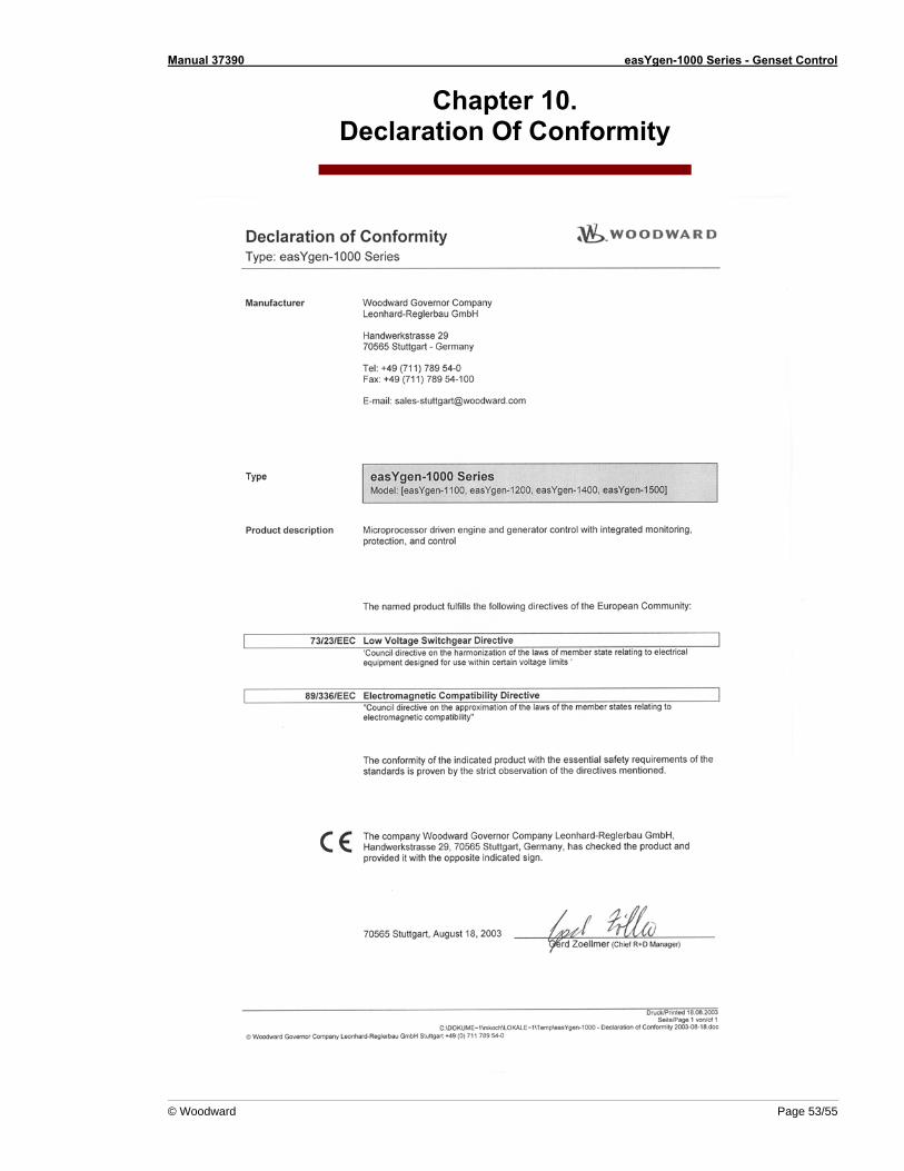
Manual 37390 easYgen-1000 Series - Genset Control
© Woodward Page 53/55
Chapter 10. Declaration Of Conformity
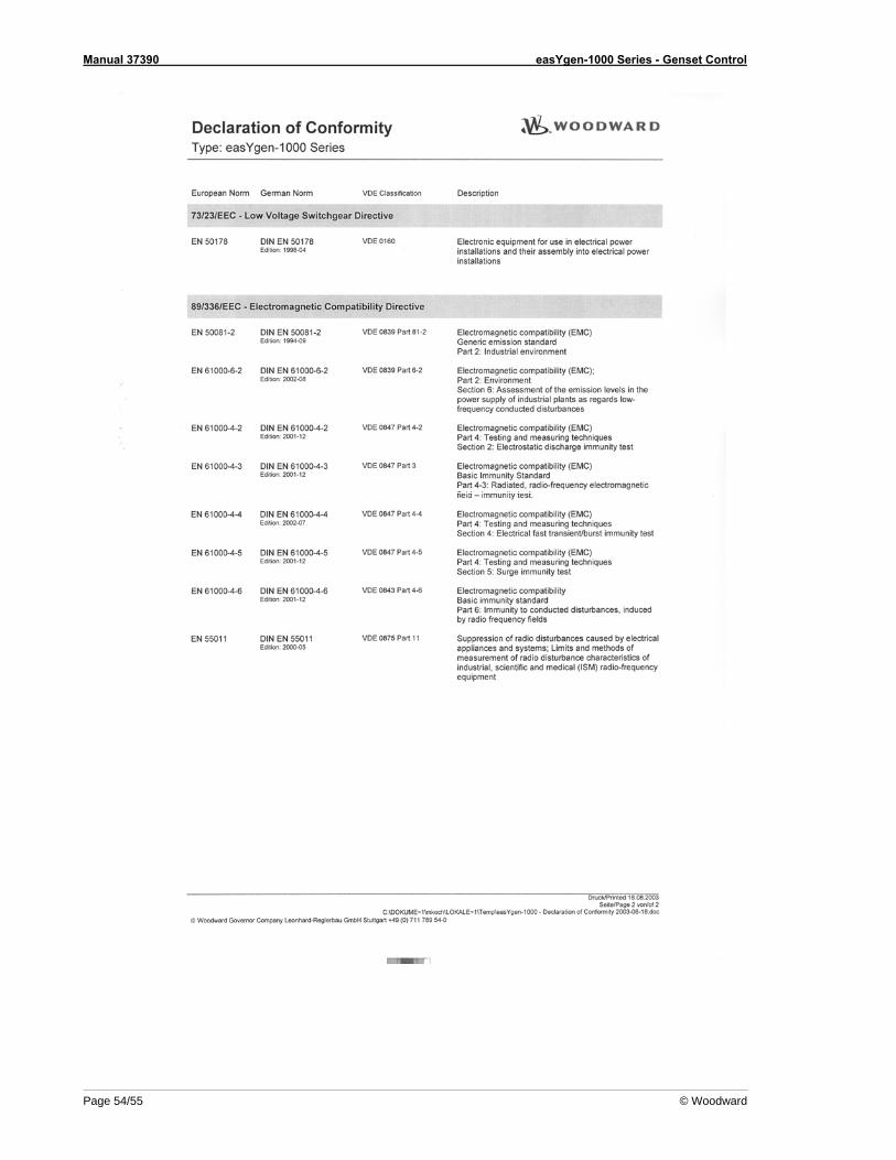
Manual 37390 easYgen-1000 Series - Genset Control
Page 54/55 © Woodward

We appreciate your comments about the content of our publications. Please send comments to: [email protected]
Please include the manual number from the front cover of this publication.
Woodward GmbH Handwerkstrasse 29 - 70565 Stuttgart - Germany
Phone +49 (0) 711 789 54-0 • Fax +49 (0) 711 789 54-100 [email protected]
Homepage
http://www.woodward.com/power
Woodward has company-owned plants, subsidiaries, and branches, as well as authorized distributors and other authorized service and sales facilities throughout the world.
Complete address/phone/fax/e-mail information
for all locations is available on our website (www.woodward.com).
2007/2/Stuttgart