Embed Size (px)
Citation preview
37218
easYgen-300 Genset Control
Operation Manual Software Version 1.0xxx
Manual 37218
Manual 37218 easYgen-300 Series - Genset Control
WARNING Read this entire manual and all other publications pertaining to the work to be performed before install-ing, operating, or servicing this equipment. Practice all plant and safety instructions and precautions. Failure to follow instructions can cause personal injury and/or property damage. The engine, turbine, or other type of prime mover should be equipped with an overspeed (overtempera-ture, or overpressure, where applicable) shutdown device(s), that operates totally independently of the prime mover control device(s) to protect against runaway or damage to the engine, turbine, or other type of prime mover with possible personal injury or loss of life should the mechanical-hydraulic gov-ernor(s) or electric control(s), the actuator(s), fuel control(s), the driving mechanism(s), the linkage(s), or the controlled device(s) fail.
CAUTION To prevent damage to a control system that uses an alternator or battery-charging device, make sure the charging device is turned off before disconnecting the battery from the system. Electronic controls contain static-sensitive parts. Observe the following precautions to prevent dam-age to these parts. • Discharge body static before handling the control (with power to the control turned off, contact a
grounded surface and maintain contact while handling the control). • Avoid all plastic, vinyl, and Styrofoam (except antistatic versions) around printed circuit boards. • Do not touch the components or conductors on a printed circuit board with your hands or with
conductive devices. Important definitions
WARNING Indicates a potentially hazardous situation that, if not avoided, could result in death or serious injury.
CAUTION indicates a potentially hazardous situation that, if not avoided, could result in damage to equipment.
NOTE Provides other helpful information that does not fall under the warning or caution categories.
d-be correct and reliable. Howe ard Governor Company assumes no responsibility
unless otherwise expressly undertaken.
© Woo pany All Rights Reserved.
Woodward Governor Company reserves the right to update any portion of this publication at any time. Information provided by Wooward Governor Company is believed to ver, Woodw
dward Governor Com
Page 2/114 © Woodward
Manual 37218 easYgen-300 Series - Genset Control
© Woodward Page 3/114
Revision History
Rev. Date Editor Change NEW 04-10-15 TP Release
Content
CHAPTER 1. GENERAL INFORMATION..........................................................................................8Related Documents.................................................................................................................................8 Overview .................................................................................................................................................9 CHAPTER 2. EASYGEN SERIES 300 OVERVIEW .........................................................................11CHAPTER 3. ELECTROSTATIC DISCHARGE AWARENESS............................................................12CHAPTER 4. HOUSING..............................................................................................................13Dimensions / Panel Cut-Out .................................................................................................................13 Installation .............................................................................................................................................14 CHAPTER 5. WIRING DIAGRAMS ...............................................................................................15CHAPTER 6. CONNECTIONS......................................................................................................19Terminal Arrangement ..........................................................................................................................19 Power supply.........................................................................................................................................20 Charging Alternator ...............................................................................................................................20 Voltage Measuring ................................................................................................................................21
Voltage Measuring: Generator ...................................................................................................22 Voltage Measuring: Mains, [350], [350X]....................................................................................24
MPU (pickup) [320X], [350X] ................................................................................................................26 Discrete Inputs ......................................................................................................................................27
Discrete Inputs: Bipolar Signals..................................................................................................27 Discrete Inputs: Operation Logic ................................................................................................28
Relay Outputs .......................................................................................................................................29 Interfaces ..............................................................................................................................................30
Overview .....................................................................................................................................30 CAN Bus - [320X], [350X] ..........................................................................................................31 DPC - Direct Configuration Cable...............................................................................................31
CHAPTER 7. OPERATION AND NAVIGATION ...............................................................................32Operation and Display ..........................................................................................................................33
Purpose of the Status LEDs .......................................................................................................33 Operating the easYgen...............................................................................................................33 Acknowledging Alarm Messages................................................................................................33 Configuring the easYgen ............................................................................................................34 Display of the Operating Values .................................................................................................34 Cycling Through the Displayed Operating Values......................................................................35 J1939 Visualization [320X], [350X].............................................................................................37 Alarm Messages .........................................................................................................................38 Configuration Displays................................................................................................................41
Manual 37218 easYgen-300 Series - Genset Control
Page 4/114 © Woodward
CHAPTER 8. FUNCTIONAL DESCRIPTION................................................................................... 44Overview............................................................................................................................................... 44 Application Modes ................................................................................................................................ 45
Application Mode 1 breaker open/close – [320], [320X], [350], [350X] ................................... 45 Application Mode 2 breakers open/close – [350], [350X] ........................................................ 45
Operating Modes .................................................................................................................................. 46 Operating Mode STOP............................................................................................................... 46 Operating Mode MANUAL.......................................................................................................... 47 Operating Mode AUTOMATIC ................................................................................................... 51
Breaker Closure Limits ......................................................................................................................... 54 Functional Description of the Oil Pressure Input DI1 ........................................................................... 55 Firing Speed Detection ......................................................................................................................... 56 Functional Description of the Charging Alternator Input/Output .......................................................... 57 Functional Description of the 2nd CB Close Delay Time....................................................................... 58 Functional Description of the Engine Released Signal ........................................................................ 59 CHAPTER 9. CONFIGURATION .................................................................................................. 60Restoring Default Values...................................................................................................................... 60
Resetting Via the Front Panel .................................................................................................... 60 Resetting Via LeoPC1................................................................................................................ 60
Configuration Via the Front Panel ........................................................................................................ 60 Configuration Using the PC.................................................................................................................. 61 Editing the Configuration File ............................................................................................................... 62 Configuring the Flags ........................................................................................................................... 62 CHAPTER 10. PARAMETERS..................................................................................................... 64Measuring ............................................................................................................................................. 65 Application ............................................................................................................................................ 66 Engine................................................................................................................................................... 67
Engine: Diesel ............................................................................................................................ 67 Engine: Pickup ........................................................................................................................... 67 Engine: Start/Stop Automatic ..................................................................................................... 68
Breaker ................................................................................................................................................. 69 Emergency Power (AMF) ..................................................................................................................... 69 Monitoring ............................................................................................................................................. 70
Monitoring: Generator ................................................................................................................ 70 Monitoring: Generator Overfrequency........................................................................................ 70 Monitoring: Generator Underfrequency ..................................................................................... 71 Monitoring: Generator Overvoltage............................................................................................ 72 Monitoring: Generator Undervoltage.......................................................................................... 73 Monitoring: Mains ....................................................................................................................... 74 Monitoring: Mains Failure Limits ................................................................................................ 74 Monitoring: Engine Overspeed................................................................................................... 76 Monitoring: Engine Underspeed................................................................................................. 77 Monitoring: Engine Start Fail ...................................................................................................... 78 Monitoring: Engine Unintended Stop ......................................................................................... 78 Monitoring: Battery Undervoltage............................................................................................... 79 Monitoring: Battery Charge Voltage ........................................................................................... 80 Monitoring: Interface................................................................................................................... 81
Discrete Inputs...................................................................................................................................... 82 Relay Outputs ....................................................................................................................................... 83 Counter ................................................................................................................................................. 84 Interfaces .............................................................................................................................................. 85
CAN Interface............................................................................................................................. 85 J1939.......................................................................................................................................... 85
System.................................................................................................................................................. 86 Parameter Access Level ............................................................................................................ 86 Flags........................................................................................................................................... 86 Versions...................................................................................................................................... 87
Manual 37218 easYgen-300 Series - Genset Control
© Woodward Page 5/114
CHAPTER 11. EVENT LOGGER..................................................................................................88GetEventLog Software..........................................................................................................................88
Installing GetEventLog................................................................................................................88 Starting GetEventLog .................................................................................................................88 Resetting the Event Logger ........................................................................................................89
CHAPTER 12. TECHNICAL DATA ...............................................................................................90CHAPTER 13. ACCURACY.........................................................................................................92APPENDIX A. COMMON ............................................................................................................93Alarm Classes .......................................................................................................................................93 Conversion Factors ...............................................................................................................................94
Conversion factors: Temperature ...............................................................................................94 Conversion factors: Pressure .....................................................................................................94
APPENDIX B. J1939 PROTOCOL DESCRIPTIONS .......................................................................95J1939 Measuring Values ......................................................................................................................95
J1939 Standard Measuring Values ............................................................................................95 Special EMR messages..............................................................................................................96 Special S6 messages .................................................................................................................96
APPENDIX C. FRONT CUSTOMIZATION ......................................................................................97APPENDIX D. TROUBLESHOOTING ............................................................................................98APPENDIX E. LIST OF PARAMETERS .......................................................................................103APPENDIX F. SERVICE OPTIONS .............................................................................................109Product Service Options .....................................................................................................................109 Returning Equipment For Repair ........................................................................................................109
Packing a Control .....................................................................................................................110 Return Authorization Number RAN ..........................................................................................110
Replacement Parts..............................................................................................................................110 How To Contact Woodward ................................................................................................................111 Engineering Services ..........................................................................................................................112 Technical Assistance ..........................................................................................................................113
Manual 37218 easYgen-300 Series - Genset Control
Page 6/114 © Woodward
Illustrations and Tables
Illustrations Figure 1-2: Functional overview................................................................................................................................................ 9 Figure 4-1: Housing - panel cut-out......................................................................................................................................... 13 Figure 5-1: Wiring diagram – easYgen 320............................................................................................................................. 15 Figure 5-2: Wiring diagram – easYgen320X........................................................................................................................... 16 Figure 5-3: Wiring diagram – easYgen350.............................................................................................................................. 17 Figure 5-4: Wiring diagram – easYgen350X........................................................................................................................... 18 Figure 6-1: easYgen-300 back view - terminal arrangement ................................................................................................... 19 Figure 6-2: Power supply......................................................................................................................................................... 20 Figure 6-3: Charging alternator input/output ........................................................................................................................... 20 Figure 6-4: Voltage measuring - generator 3Ph 4W ................................................................................................................ 22 Figure 6-5: Voltage measuring - generator 3Ph 3W ................................................................................................................ 22 Figure 6-6: Voltage measuring - generator 1Ph 3W ................................................................................................................ 22 Figure 6-7: Voltage measuring - generator 1Ph 2W ................................................................................................................ 23 Figure 6-8: Voltage measuring - mains 3Ph 4W...................................................................................................................... 24 Figure 6-9: Voltage measuring - mains 3Ph 3W...................................................................................................................... 24 Figure 6-10: Voltage measuring - mains 1Ph 3W.................................................................................................................... 24 Figure 6-11: Voltage measuring - mains 1Ph 2W.................................................................................................................... 25 Figure 6-12: MPU - principle overview................................................................................................................................... 26 Figure 6-13: MPU input........................................................................................................................................................... 26 Figure 6-14: Minimum required input voltage depending on frequency ................................................................................. 26 Figure 6-15: Discrete inputs - alarm/control input - positive signal ....................................................................................... 27 Figure 6-16: Discrete inputs - alarm/control input - negative signal....................................................................................... 28 Figure 6-17: Discrete inputs - alarm/control inputs - operation logic ...................................................................................... 28 Figure 6-18: Relay outputs ...................................................................................................................................................... 29 Figure 6-19: Interfaces - overview........................................................................................................................................... 30 Figure 6-20: Interfaces - CAN bus........................................................................................................................................... 31 Figure 6-21: Interfaces - CAN bus - wiring of shielding ......................................................................................................... 31 Figure 6-22: Interfaces - CAN bus – schematic wiring and termination.................................................................................. 31 Figure 7-1: Front panel and display ......................................................................................................................................... 32 Figure 7-2: 6 digit 7 segment LED display.............................................................................................................................. 34 Figure 7-3: J1939 fault display ................................................................................................................................................ 38 Figure 7-4: Additional alarm display ....................................................................................................................................... 39 Figure 8-2: Discrete input DI1 - oil pressure ........................................................................................................................... 55 Figure 8-3: Starting procedure ................................................................................................................................................. 55 Figure 8-4: Charging alternator input/output ........................................................................................................................... 57 Figure 8-5: AMF application with engine released signal ....................................................................................................... 59 Figure 9-1: Configurable display flags .................................................................................................................................... 62 Figure 9-2: Flag configuration default ..................................................................................................................................... 63 Figure 9-3: Flag configuration custom..................................................................................................................................... 63 Figure 10-1: Voltage/frequency hysteresis .............................................................................................................................. 75 Figure 10-2: Configurable display flags .................................................................................................................................. 86 Figure 11-1: GetEventLog - interface configuration................................................................................................................ 88 Figure 11-2: GetEventLog – event logger content................................................................................................................... 89 Figure 13-1: Paper strips.......................................................................................................................................................... 97
Manual 37218 easYgen-300 Series - Genset Control
© Woodward Page 7/114
Tables Table 1-1: Manual - overview.................................................................................................................................................... 8 Table 2-1: easYgen series 300 product features....................................................................................................................... 11 Table 4-1: Housing - panel cut-out .......................................................................................................................................... 13 Table 6-1: Power supply - terminal assignment....................................................................................................................... 20 Table 6-2: Charging alternator input/output - terminal assignment ......................................................................................... 20 Table 6-3: Voltage measuring principles ................................................................................................................................. 21 Table 6-4: Voltage measuring - terminal assignment - generator voltage................................................................................ 23 Table 6-5: Voltage measuring - terminal assignment - mains voltage ..................................................................................... 25 Table 6-6: MPU - terminal assignment .................................................................................................................................... 26 Table 6-7: Discrete input - terminal assignment - alarm/control input - positive signal .......................................................... 27 Table 6-8: Discrete input - terminal assignment - alarm/control inputs - negative signal........................................................ 28 Table 6-9: Relay outputs - terminal assignment, part 1 ........................................................................................................... 29 Table 6-10: Relay outputs – configurable parameters.............................................................................................................. 29 Table 6-11: Interfaces - connection overview.......................................................................................................................... 30 Table 7-1: Display of operating values .................................................................................................................................... 36 Table 7-2: J 1939 messages ..................................................................................................................................................... 38 Table 7-3: Alarm classes.......................................................................................................................................................... 39 Table 7-4: Alarm messages...................................................................................................................................................... 40 Table 7-5: Configuration displays............................................................................................................................................ 43 Table 8-1: Functional description - Overview ......................................................................................................................... 44 Table 8-1: Discrete input DI1 - oil pressure............................................................................................................................. 55 Table 10-1: Relay outputs - list of configurable parameters .................................................................................................... 83 Table 11-1: Event logger - operation states ............................................................................................................................. 89
Manual 37218 easYgen-300 Series - Genset Control
Page 8/114 © Woodward
Chapter 1. General Information
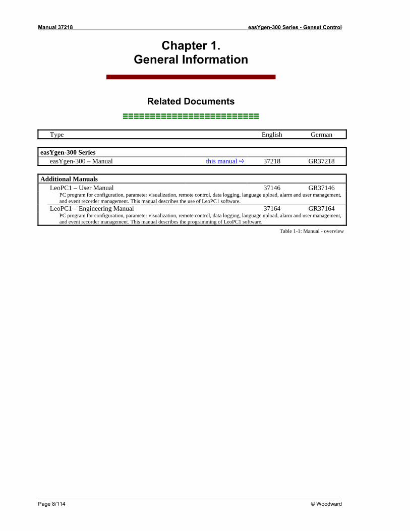
Related Documents ≡≡≡≡≡≡≡≡≡≡≡≡≡≡≡≡≡≡≡≡≡≡≡≡≡
Type English German easYgen-300 Series easYgen-300 – Manual this manual 37218 GR37218 Additional Manuals LeoPC1 – User Manual 37146 GR37146 PC program for configuration, parameter visualization, remote control, data logging, language upload, alarm and user management,
and event recorder management. This manual describes the use of LeoPC1 software. LeoPC1 – Engineering Manual 37164 GR37164 PC program for configuration, parameter visualization, remote control, data logging, language upload, alarm and user management,
and event recorder management. This manual describes the programming of LeoPC1 software.
Table 1-1: Manual - overview
Manual 37218 easYgen-300 Series - Genset Control
© Woodward Page 9/114
Overview ≡≡≡≡≡≡≡≡≡≡≡≡≡≡≡≡≡≡≡≡≡≡≡≡≡
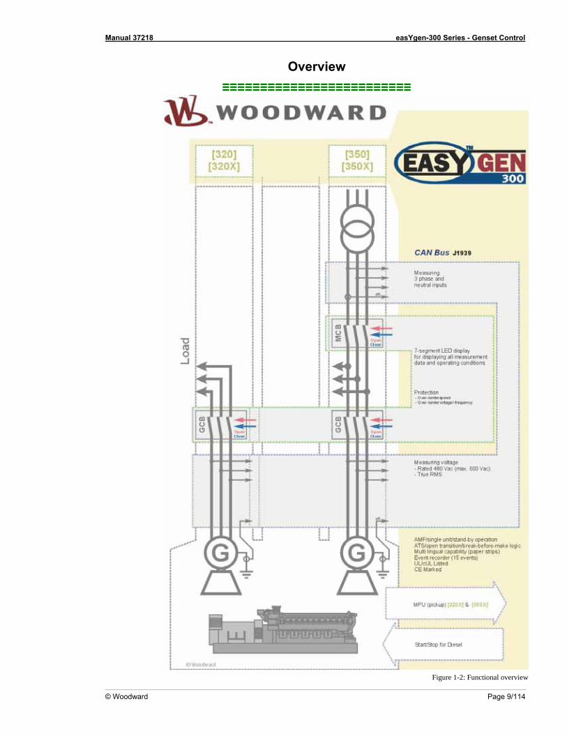
Figure 1-2: Functional overview
Manual 37218 easYgen-300 Series - Genset Control
Page 10/114 © Woodward
The easYgen-300 Series generator set control ions:
• Gen-set control• Engine and gen• Engine data measurement -
o including oil pressure and temperature, coolant temperature, battery voltage, speed,
r trip and engine shutdown ic mains failu genset th autom gine start on failure
open transition breaker control s communications t gine controllers and plant managem t systems
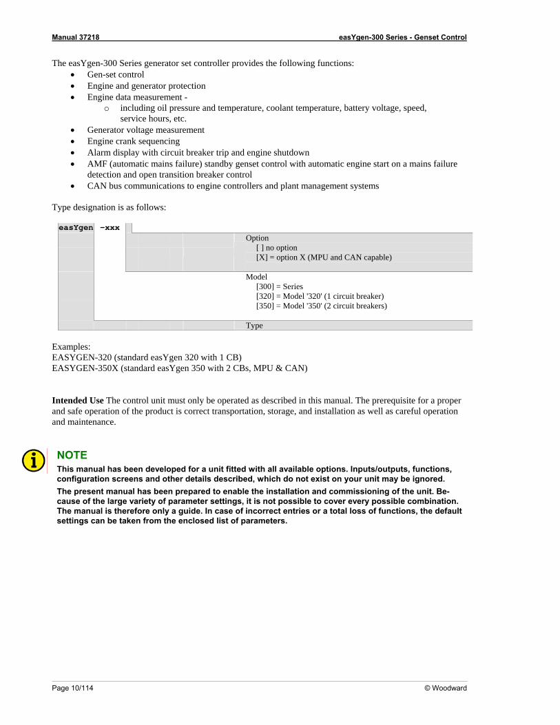
T esignation is as follows:
ler provides the following funct erator protection
service hours, etc. • Generator voltage measurement • Engine crank sequencing • Alarm display with circuit breake• AMF (automat
dre) standby control wi atic en a mains
detection an• CAN bu o en en
ype d
easYgen -xxx
Option [ ] no option [X] = option X (MPU and CAN capable)
[320] = Model '320' (1 circuit breaker) [350] = Model '350' (2 circuit breakers)
Model [300] = Series
Type E
ASYGEN-350X (standard easYgen 350 with 2 CBs, MPU & CAN)
I ntrol unit must only be operated as described in this manual. The prerequisite for a proper and roduct is correct transportation, storage, and installation as well as careful operation and ma
xamples: EE
ASYGEN-320 (standard easYgen 320 with 1 CB)
ntended Use The co safe operation of the p
intenance.
NOTE This manual has been developed for a unit fitted with all available options. Inputs/outputs, functions, configuration screens and other details described, which do not exist on your unit may be ignored. The present manual has been prepared to enable the installation and commissioning of the unit. Be-cause of the large variety of parameter settings, it is not possible to cover every possible combination. The manual is therefore only a guide. In case of incorrect entries or a total loss of functions, the default settings can be taken from the enclosed list of parameters.
Manual 37218 easYgen-300 Series - Genset Control
© Woodward Page 11/114
Chapter 2. easYgen Series 300 Overview
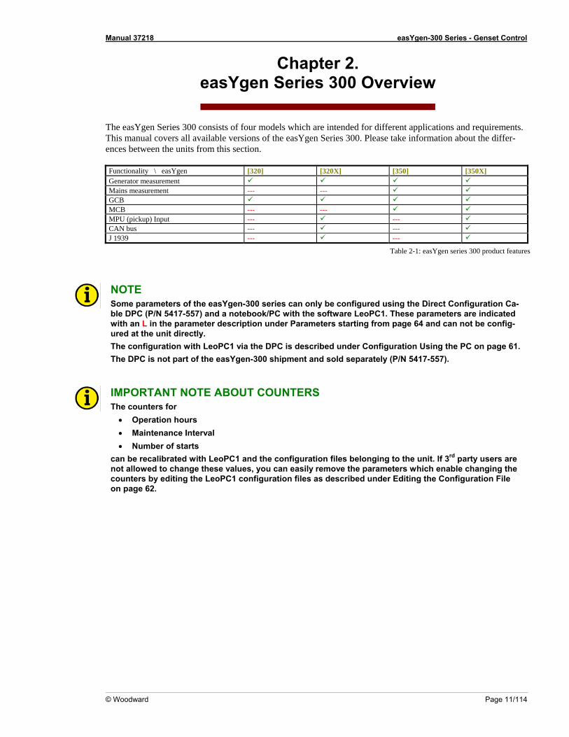
The easYgen Series 300 consists of four models which are intended for different applications and requirements. This manual covers all available versions of the easYgen Series 300. Please take information about the differ-nces between the units from this section.
[320] [320X] [350] [350X]
e Functionality \ easYgen Generator measurement Mains measurement --- --- GCB MC --- --- B MP pickup) Input --- --- U (CAN bus --- --- J 1939 --- ---
Table 2-1: easYgen series 300 product features
NOTE
mble Dwith and can not be config-ured at the unit directly. The c page 61. The DPC is n separately (P/N 5417-557).
So e parameters of the easYgen-300 series can only be configured using the Direct Configuration Ca-PC (P/N 5417-557) and a notebook/PC with the software LeoPC1. These parameters are indicated an L in the parameter description under Parameters starting from page 64
onfiguration with LeoPC1 via the DPC is described under Configuration Using the PC onot part of the easYgen-300 shipment and sold
IMPThe cou r
•
• Ma• Nu
can be recalibrated with LeoPC1 and the configuration files belonging to the unit. If 3rd party users are not allowed to change these values, you can easily remove the parameters which enable changing the
iting the LeoPC1 configuration files as described under Editing the Configuration File
ORTANT NOTE ABOUT COUNTERS nters fo
Operation hours intenance Interval mber of starts
counters by edon page 62.
Manual 37218 easYgen-300 Series - Genset Control
Page 12/114 © Woodward
Chapter 3. Electrostatic Discharge Awareness
All electronic equipment is static-sensitive, some components more than others. To protect these components from static damage, you must tak ectrostatic discharges. Follow these precautions when
Before performing maintenance on the electronic control, discharge the static electricity on your body to ground by touching and holding a grounded metal object (pipes, cabinets, equipment, etc.).
2. Avoid the build-up of static electricity on your body by not wearing clothing made of synthetic materials.
Wear cotton or cotton-blend materials as much as possible because these do not store static electric char-ges as much as synthetics.
3. Keep plastic, vinyl, and Styrofoam materials (such as plastic or Styrofoam cups, cup holders, cigarette
packages, cellophane wrappers, vinyl books or folders, plastic bottles, and plastic ash trays) away from the control, the modules, and the work area as much as possible.
4. Opening the control cover may void the unit warranty.
Do not remove the Printed Circuit Board (PCB) from the control cabinet unless absolutely necessary. If you must remove the PCB from the control cabinet, follow these precautions:
• Ensure that the device is completely de-energized (all connectors must be disconnected).
• Do not touch any part of the PCB except the edges.
• Do not touch the electrical conductors, connectors, or components with conductive devices with your
hands.
• When replacing a PCB, keep the new PCB in the protective antistatic bag it comes in until you are ready to install it. Immediately after removing the old PCB from the control cabinet, place it in the protective antistatic bag.
e special precautions to minimize or eliminate el
working with or near the control. 1.
CAUTION To prevent damage to elect onents caused by imprope g, rea erve the pre-cautions in Woodward manual 82715, Guide for Handling Pro of Electro , Printed Circuit Boards, and Module
ronic comp r handlin d and obs and tection nic Controls
s.
Manual 37218 easYgen-300 Series - Genset Control
© Woodward Page 13/114
Chapter 4. Housing
Dimensions / Panel Cut-Out ≡≡≡≡≡≡≡≡≡≡≡≡≡≡≡≡≡≡≡≡≡≡≡≡≡
40
136158
136
158
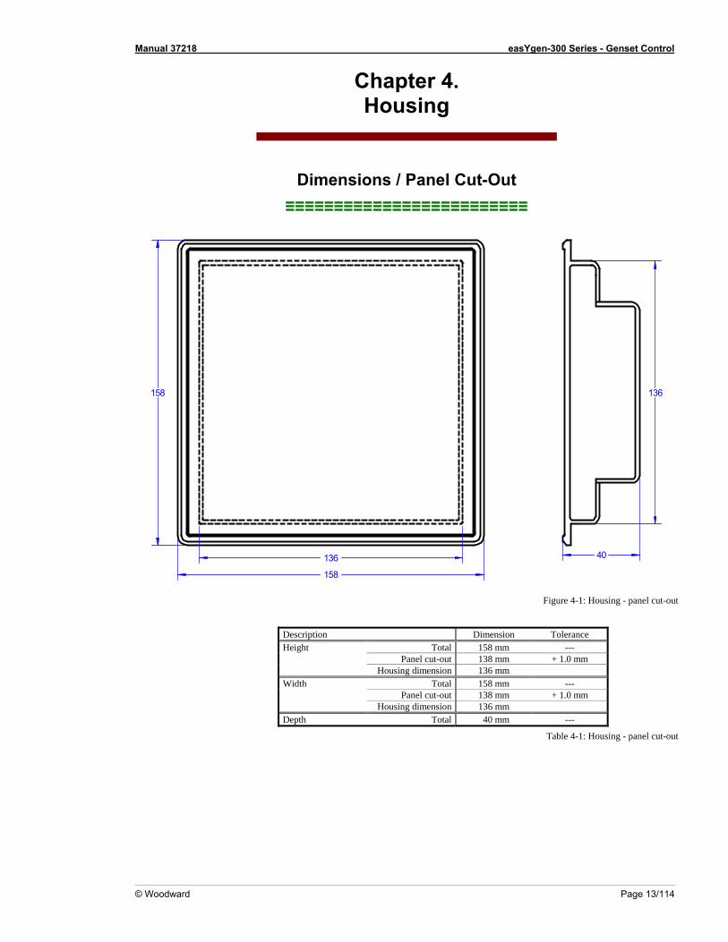
Figure 4-1: Housing - panel cut-
on Tolerance
out
Description DimensiHeight Total 158 mm --- Panel cut-out 138 mm + 1.0 mm Housing dimension 136 mm Width Total 158 mm --- Panel cut-out 138 mm + 1.0 mm Housing dimension 136 mm Depth Total 40 mm ---
Table 4-1: Housing - panel cut-out
Manual 37218 easYgen-300 Series - Genset Control
Page 14/114 © Woodward
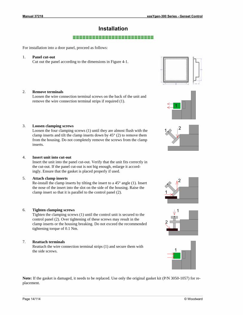
≡≡≡≡≡≡≡≡≡≡≡≡≡≡≡≡≡≡≡≡≡≡≡≡≡ For installation into a door panel, proceed as follows: 1. Panel cut-out
Cut out the panel according to the dimensions in Figure 4-1.
Installation
2. Remove terminals
Loosen the wire connection terminal screws on the back of the unit and remove the wire connection terminal strips if required (1).
1
3. Loosen clamping screws Loosen the four clamping screws (1) until they are almost flush with the clamp inserts and tilt the clamp inserts down by 45° (2) to remove them from the housing. Do not completely remove the screws from the clamp inserts.
1 2
4. Insert unit into cut-out Insert the unit into the panel cut-out. Verify that the unit fits correctly in the cut-out. If the panel cut-out is not big enough, enlarge it accord-ingly. Ensure that the gasket is placed properly if used.
5. Attach clamp inserts
Re-install the clamp inserts by tilting the insert to a 45° angle (1). Insert the nose of the insert into the slot on the side of the housing. Raise the clamp insert so that it is parallel to the control panel (2).
1
2
6. Tighten clamping screws Tighten the clamping screws (1) until the control unit is secured to the control panel (2). Over tightening of these screws may result in the clamp inserts or the housing breaking. Do not exceed the recommended tightening torque of 0.1 Nm.
1
2
7. Reattach terminals Reattach the wire connection terminal strips (1) and secure them with the side screws.
1
Note: If the gasket is damaged, it needs to be replaced. Use only the original gasket kit (P/N 3050-1057) for re-placement.
Manual 37218 easYgen-300 Series - Genset Control
© Woodward Page 15/114
Chapter 5. Wiring Diagrams
Battery
2004-09-21 | easYgen-300 Wiring Diagram eYg300ww-0439-ap.skfSubject to technical mocifications.
The socket for the PC configurationis situated on the back of the item.This is where the DPChas to be plugged in.
D+, 12 Vdc (charge alternator)D+, 24 Vdc (charge alternator)
12
65
151617181920
89
33
35
34
10
11121314
G
B+
D+
Common
Free programmable (relay 4)
Fuel relay (relay 5)
Crank (relay 6)
Generator voltage L1
Generator voltage N
Common
GCB close (relay 2)
DI1 Oil pressure
DI2 Coolant temperature
DI3 Remote start
DI5 Reply GCB / free progr.
N L3 L2 L1
GCB
Engine
Auxiliaryalternator
L3N L2 L1
easy
gen
320
(gen
set c
ontro
l)
DI4 free programmable
7not connected
not connected
not connected
not connected
34not connected
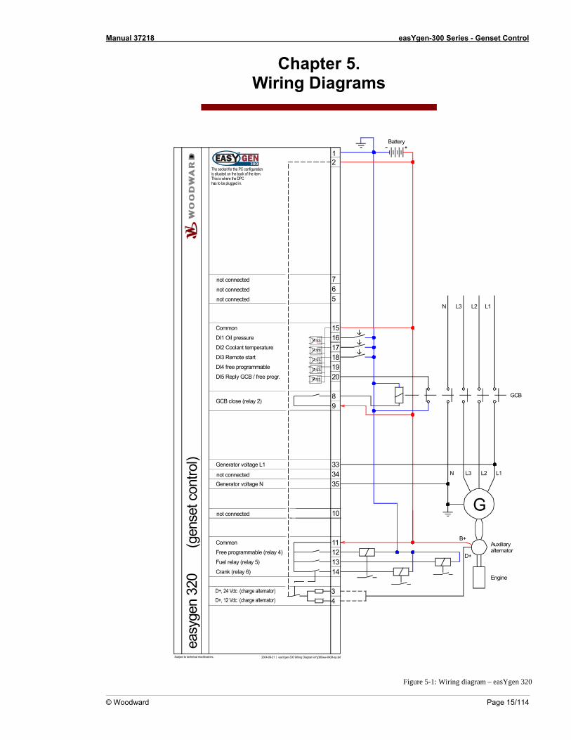
Figure 5-1: Wiring diagram – easYgen 320
Manual 37218 easYgen-300 Series - Genset Control
Page 16/114 © Woodward
Battery
2004-09-21 | easYgen-300 Wiring Diagram eYg300ww-0439-ap.skfSubject to technical mocifications.
The socket for the PC configurationis situated on the back of the item.This is where the DPChas to be plugged in.
D+, 12 Vdc (charge alternator)D+, 24 Vdc (charge alternator)
12
65
151617181920
89
29
31
33
35
34
10
11121314
G
B+
D+Common
Free programmable (relay 4)
Fuel relay (relay 5)
Crank (relay 6)
Generator voltage L3
Generator voltage L2
Generator voltage L1
Generator voltage N
Common
GCB close (relay 2)
DI1 Oil pressure
DI2 Coolant temperature
DI3 Remote start
DI5 Reply GCB / free progr.
N L3 L2 L1
GCB
Engine
Auxiliaryalternator
37383940
MPU +
CAN-L
MPU -
CAN-H
L3N L2 L1
Xea
syge
n 32
0
(g
ense
t con
trol)
DI4 free programmable
7not connected
not connected
not connected
not connected
34not connected
36not connected
32not connected
30not connected
ECU
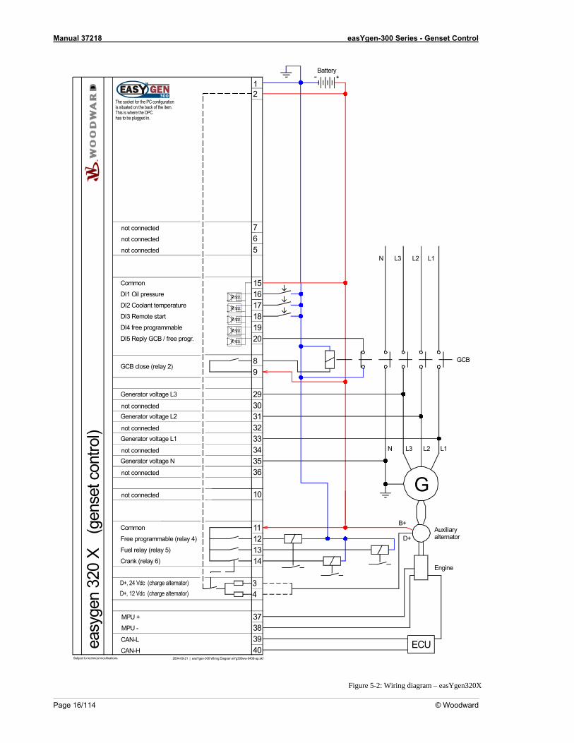
Figure 5-2: Wiring diagram – easYgen320X
Manual 37218 easYgen-300 Series - Genset Control
Mains voltage N
Battery
The socket for the PC configurationis situated on the back of the item.This is where the DPChas to be plugged in.
12
21
23
25
27
65
151617181920
89
33Generator voltage L1
Common
GCB close (relay 2)
DI1 Oil pressure
DI2 Coolant temperature
DI3 Remote start
DI4 Reply MCB / free progr.
DI5 Reply GCB / free progr.
Mains voltage L3
Mains voltage L2
Mains voltage L1
N L3 L2 L1
L3N L2 L1
GCB
MCBMCB open (relay 1)
L3N L2 L1
DI4 Reply MCB / free progr.
7
34not connected
22
24
26
28not connected
not connected
not connected
not connected
not connected
not connected
not connected
30
32
34
29not connected
31not connected
2004-09-21 | easYgen-300 Wiring Diagram eYg300ww-0439-ap.skfSubject to technical mocifications.
D+, 12 Vdc (charge alternator)D+, 24 Vdc (charge alternator)
35
34
10
11121314
G
B+
D+Common
Free programmable (relay 4)
Fuel relay (relay 5)
Crank (relay 6)
Free programmable (relay 3)
Generator voltage N
Engine
Auxiliaryalternator
easy
gen
350
(gen
set c
ontro
l)
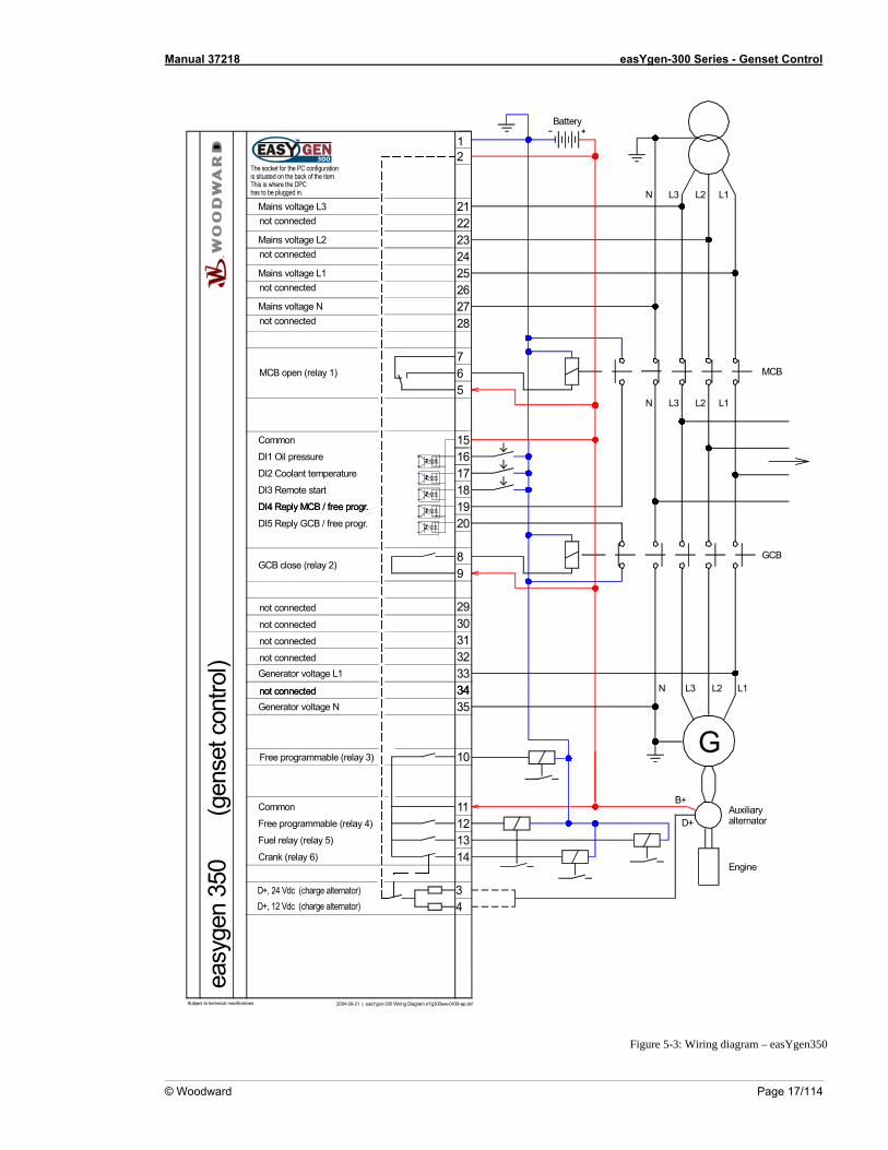
Figure 5-3: Wiring diagram – easYgen350
© Woodward Page 17/114
Manual 37218 easYgen-300 Series - Genset Control
Mains voltage N
Battery
2004-09-21 | easYgen-300 Wiring Diagram eYg300ww-0439-ap.skfSubject to technical mocifications.
The socket for the PC configurationis situated on the back of the item.This is where the DPChas to be plugged in.
D+, 12 Vdc (charge alternator)D+, 24 Vdc (charge alternator)
12
21
Page 18/114 © Woodward
23
25
27
65
151617181920
89
29
31
33
35
34
10
11121314
G
B+
D+Common
Free programmable (relay 4)
Fuel relay (relay 5)
Crank (relay 6)
Free programmable (relay 3)
Generator voltage L3
Generator voltage L2
Generator voltage L1
Generator voltage N
Common
GCB close (relay 2)
DI1 Oil pressure
DI2 Coolant temperature
DI3 Remote start
DI4 Reply MCB / free progr.
DI5 Reply GCB / free progr.
Mains voltage L3
Mains voltage L2
Mains voltage L1
N L3 L2 L1
L3N L2 L1
GCB
MCBMCB open (relay 1)
Engine
Auxiliaryalternator
37383940
MPU +
CAN-L
MPU -
CAN-H
L3N L2 L1
easy
gen
350
(gen
set c
ontro
l)X
DI4 Reply MCB / free progr.
7
34not connected
36not connected
32not connected
30not connected
22
24
26
28not connected
not connected
not connected
not connected
not connected
not connected
not connected
not connected
30
32
34
36
ECU
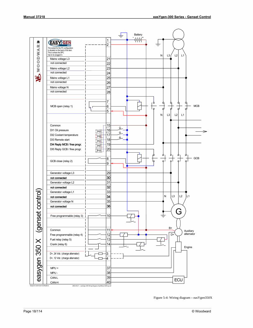
Figure 5-4: Wiring diagram – easYgen350X
Manual 37218 easYgen-300 Series - Genset Control
© Woodward Page 19/114
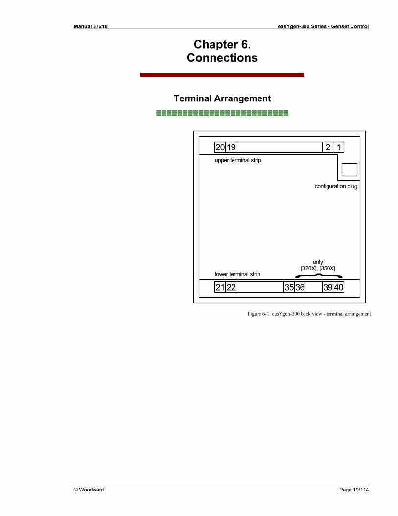
Chapter 6. Connections
Terminal Arrangement ≡≡≡≡≡≡≡≡≡≡≡≡≡≡≡≡≡≡≡≡≡≡≡≡≡
20 19 12
21 22 403935 36
upper terminal strip
lower terminal strip
configuration plug
only[320X], [350X]
Figure 6-1: ea
sYgen-300 back view - terminal arrangement
Manual 37218 easYgen-300 Series - Genset Control
Page 20/114 © Woodward
Power supply ≡≡≡≡≡≡≡≡≡≡≡≡≡≡≡≡≡≡≡≡≡≡≡≡≡
Power supply
21
6.5 to 32.0 Vdc
0 Vdc6.5 to 32.0 Vdc
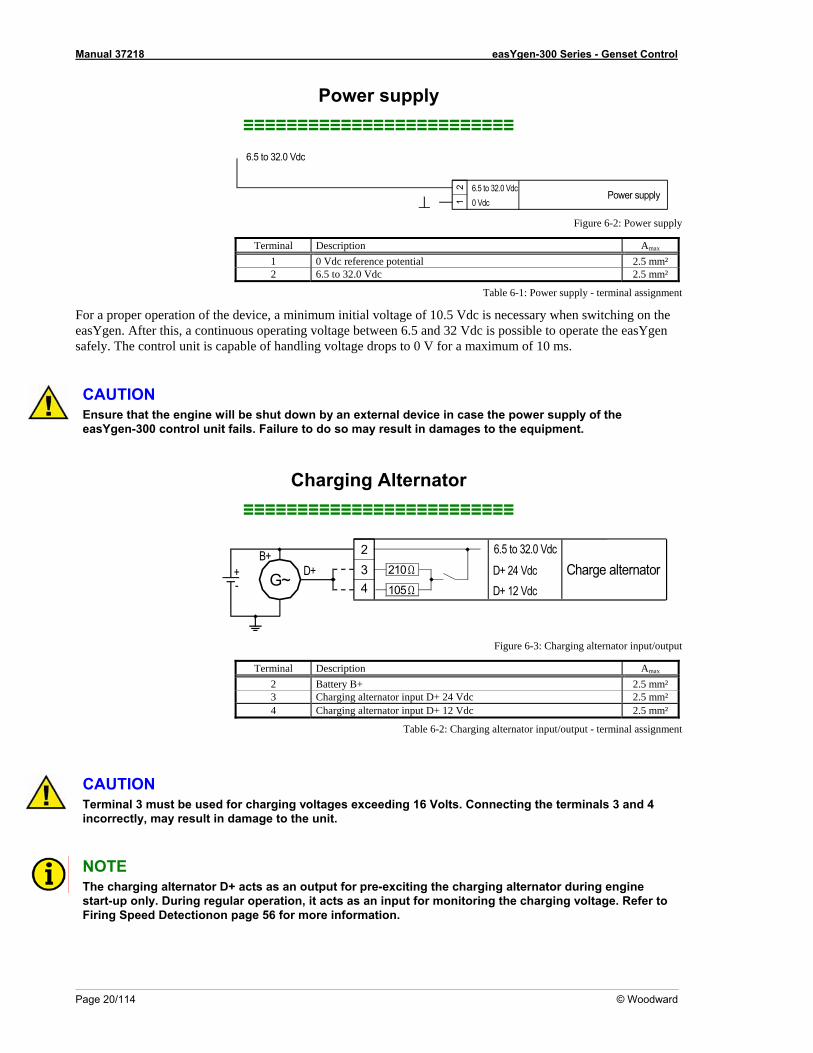
Figure 6-2: Power supply
Terminal Description Amax
1 0 Vdc reference potential 2.5 mm² 2 6.5 to 32.0 Vdc 2.5 mm²
Table 6-1: Power supply - terminal assignment
For a proper operation of the device, a mieasYgen. After this, a continuous operatisafely. The control unit is capab
nimum initial voltage of 10.5 Vdc is necessary when switching on the ng voltage between 6.5 and 32 Vdc is possible to operate the easYgen dling voltage drops to 0 V for a maximum of 10 ms. le of han
CAUTION Ensure that the engine will b oeasYgen-300 control unit fails. Failure lt in damages to the equipment.
Charging Alternator ≡≡≡≡≡≡≡≡≡≡≡≡≡≡≡≡≡≡≡≡≡≡≡≡≡
e shut d wn by an external device in case the power supply of the to do so may resu
Charge alternator23
6.5 to 32.0 Vdc
4210 Ω
105 Ω
D+B+
D+ 12 VdcD+ 24 Vdc+
- G~
t/output
Terminal Description Amax
Figure 6-3: Charging alternator inpu
2 Battery B+ 2.5 mm² 3 Charging alternator input D+ 24 Vdc 2.5 mm² 4 Charging alternator input D+ 12 Vdc 2.5 mm²
Table 6-2: Charging alternator input/output - terminal assignment
CAUTION Terminal 3 must be used for charging voltages exceeding 16 Volts. Connecting the terminals 3 and 4 incorrectly, may result in damage to the unit.
NOTE The charging alternator D+ acts as an output for pre-exciting the charging alternator during engine start-up only. During regular operation, it acts as an input for monitoring the charging voltage. Refer to Firing Speed Detectionon page 56 for more information.
Manual 37218 easYgen-300 Series - Genset Control
© Woodward Page 21/114
ltage Measuring ≡≡≡≡≡≡≡≡
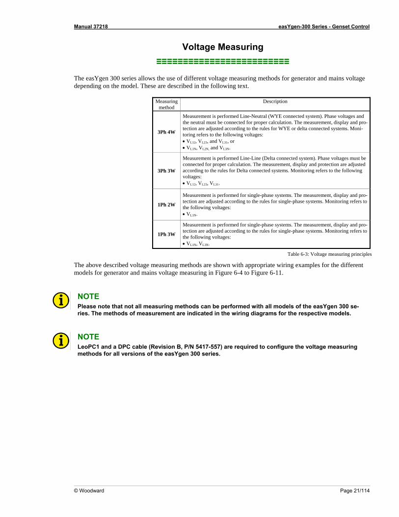
The easYgen 300 series allows the use of different voltage measuring methods for generator and mains voltage depending on the model. These are described in the following text.
Measuring method
Description
Vo≡≡≡≡≡≡≡≡≡≡≡≡≡≡≡≡≡
3Ph 4W
Measurement is performed Line-Neutral (WYE connected system). Phase voltages and the neutral must be connected for proper calculation. The measurement, display and pro-tection are adjusted according to the rules for WYE or delta connected systems. Moni-toring refers to the following voltages: • VL12, VL23, and VL31, or • VL1N, VL2N, and VL3N.
3Ph 3W
Measurement is performed Line-Line (Delta connected system). Phase voltages must be connected for proper calculation. The measurement, display and protection are adjusted according to the rules for Delta connected systems. Monitoring refers to the following voltages: • VL12, VL23, VL31.
1Ph 2W tection are adjusted accordinthe following volta
Measurement is performed for single-phase systems. The measurement, display and pro-g to the rules for single-phase systems. Monitoring refers to
ges: • VL1N.
1Ph 3W
Measurement is performed for single-phase systems. The measurement, display and pro-tection are adjusted according to the rules for single-phase systems. Monitoring refers to the following voltages: • VL1N, VL3N.
Table 6-3: Voltage measuring principles
The above described voltage measuring methods are shown with appropriate wiring examples for the different models for generator and mains voltage measuring in Figure 6-4 to Figure 6-11. NOTE Please note that not all measuring methods can be performed with all models of the easYgen 300 se-ries. The methods of measurement are indicated in the wiring diagrams for the respective models.
NOTE LeoPC1 and a DPC cable (Revision B, P/N 5417-557) are required to configure the voltage measuring methods for all versions of the easYgen 300 series.
Manual 37218 easYgen-300 Series - Genset Control
Page 22/114 © Woodward
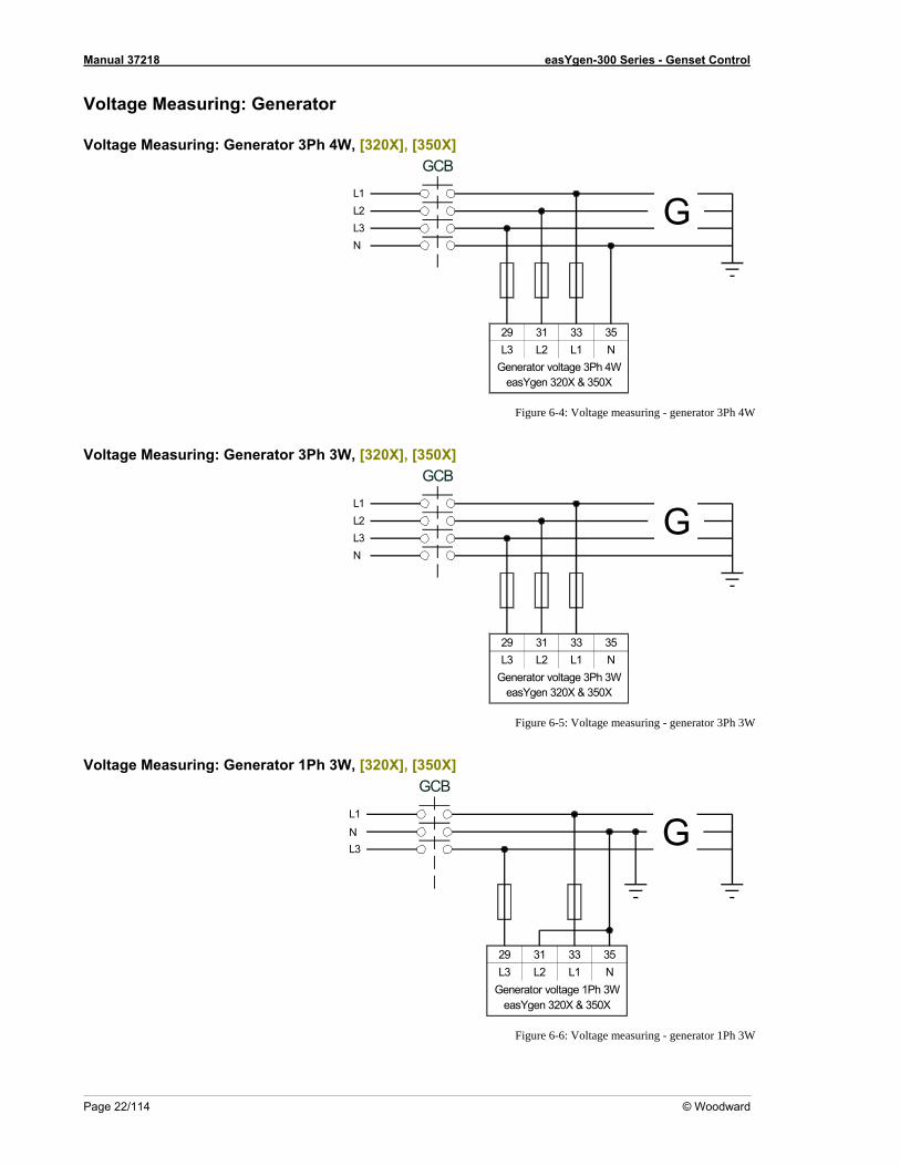
Voltage Measuring: Generator
Voltage Measuring: Generator 3Ph 4W, [320X], [350X]
L1L2L3N
GCB
29 31 33 35L3 L2 L1 N
Generator voltage 3Ph 4WeasYgen 320X & 350X
G
Figure 6-4: Voltage measuring - generato 4W r 3Ph
Voltage Measuring: Generator h 3W 3P , [320X], [350X]
L1L2L3N
GCB
29 31 33 35L3 L2 L1 N
Generator voltage 3Ph 3WeasYgen 320X & 350X
G
Figure 6-5: Voltage measuring - generator 3Ph 3W
Voltage Measuring: Generator 1Ph 3W, [320X], [350X]
L1
L3N
GCB
G
29 31 33 35L3 L2 L1 N
Generator voltage 1Ph 3WeasYgen 320X & 350X
Figure 6-6: Voltage measuring - generator 1Ph 3W
Manual 37218 easYgen-300 Series - Genset Control
© Woodward Page 23/114
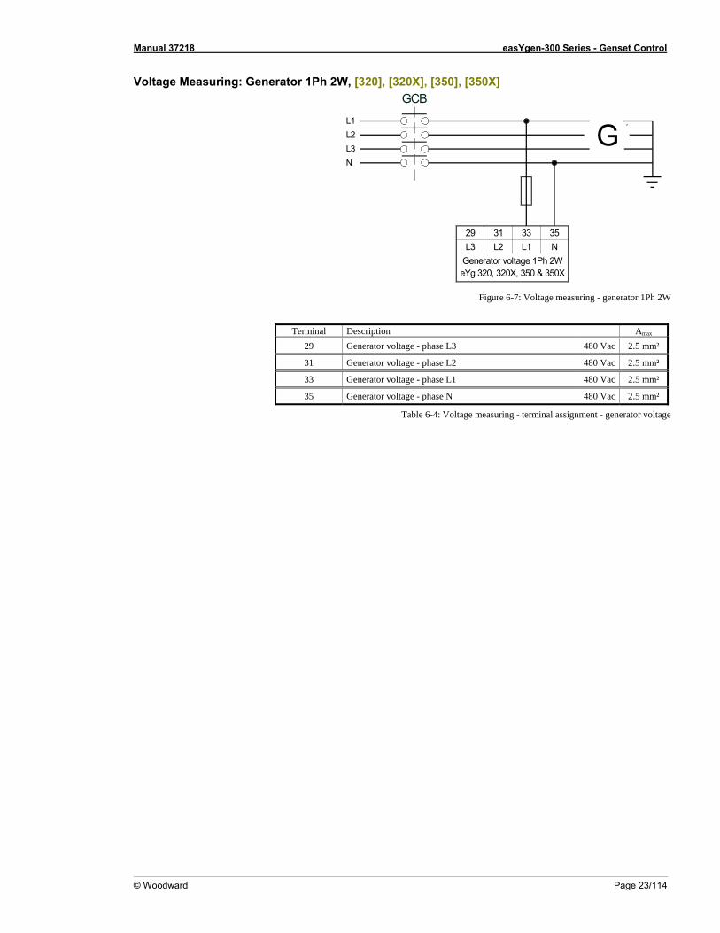
Voltage Measuring: Generator 1Ph 2W, [320], [320X], [350], [350X]
L1L2L3N
GCB
29 31 33 35L3 L2 L1 N
Generator voltage 1Ph 2WeYg 320, 320X, 350 & 350X
G
Figure 6-7: Voltage measuring - generator 1Ph 2W
Terminal Description Amax
29 Generator voltage - phase L3 480 Vac 2.5 mm²
31 Generator voltage - phase L2 480 Vac 2.5 mm²
33 Generator voltage - phase L1 480 Vac 2.5 mm²
35 Generator voltage - phase N 480 Vac 2.5 mm²
Table 6-4: Voltage measuring - terminal assignment - generator voltage
Manual 37218 easYgen-300 Series - Genset Control
Page 24/114 © Woodward
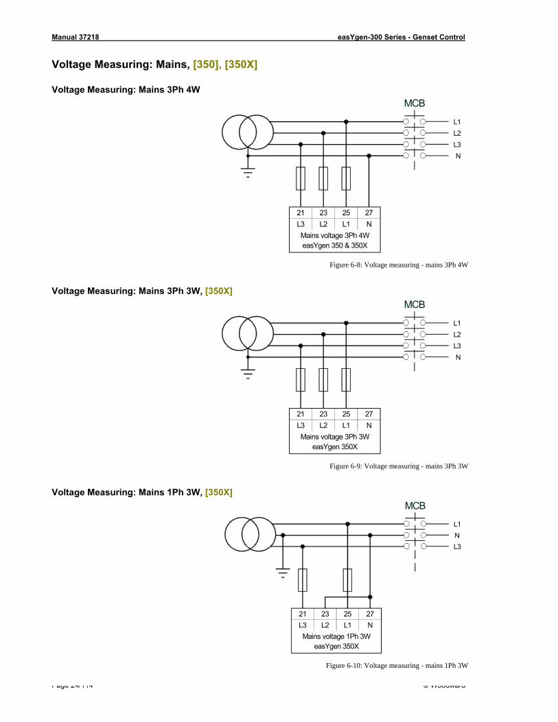
0X] Voltage Measuring: Mains, [350], [35
Voltage Measuring: Mains 3Ph 4W
21 23 25 27L3 L2 L1 NMains voltage 3Ph 4WeasYgen 350 & 350X
MCB
L1L2L3N
Figure 6-8: Voltage measuring - mains 3Ph 4W
Voltage Measuring: Mains 3Ph 3W, [350X]
21 23 25 27L3 L2 L1 NMains voltage 3Ph 3W
easYgen 350X
MCB
L1L2L3N
Figure 6-9: Voltage measuring - mains 3Ph 3W
Voltage Measuring: Mains 1Ph 3W, [350X]
21 23 25 27L3 L2 L1 NMains voltage 1Ph 3W
easYgen 350X
MCB
L1
L3N
Figure 6-10: Voltage measuring - mains 1Ph 3W
Manual 37218 easYgen-300 Series - Genset Control
© Woodward Page 25/114
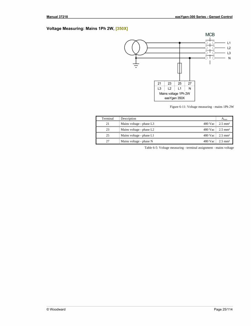
Voltage Measuring: Mains 1Ph 2W, [350X]
L1L2L3
21 23 25 27L3 L2 L1 NMains voltage 1Ph 2W
easYgen 350X
MCB
N
Figure 6-11: Voltage m
Terminal Description Amax
easuring - mains 1Ph 2W
21 Mains voltage - phase L3 480 Vac 2.5 mm²
23 Mains voltage - phase L2 480 Vac 2.5 mm²
25 Mains voltage - phase L1 480 Vac 2.5 mm²
27 Mains voltage - phase N 480 Vac 2.5 mm²
Table 6-5: Voltage measuring - terminal assignment - mains voltage
Manual 37218 easYgen-300 Series - Genset Control
Page 26/114 © Woodward
MPU ( 50X]
pickup) [320X], [3≡≡≡≡≡≡≡≡≡≡≡≡≡≡≡≡≡≡≡≡≡≡≡≡≡
Sensor
toPickup
input
Rotating shaft
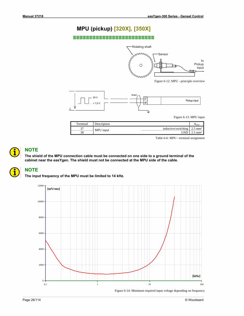
Figure 6-12: MPU - principle overview
< 1,0 V
24 VPickup input37
38
Shield
Figure 6-13: MPU input
Terminal Description Amax
37 inductive/switching 2.5 mm²38
MPU input GND 2.5 mm²
Table 6-6: MPU - terminal assignment
NOTE The shield of the MPU connection cable must be connected on one side to a ground terminal of the cabinet near the easYgen. The shield must not be connected at the MPU side of the cable.
NOTE The input frequency of the MPU must be limited to 14 kH z.
0
2000
4000
6000
8000
10000
12000
0,1 1 10 100
[mVrms]
[kHz]
Figure 6-14: Minimum required input voltage depending on frequency
Manual 37218 easYgen-300 Series - Genset Control
© Woodward Page 27/114
Discrete Inputs ≡≡≡≡≡≡≡≡≡≡≡≡≡≡≡≡≡≡≡≡≡≡≡≡≡
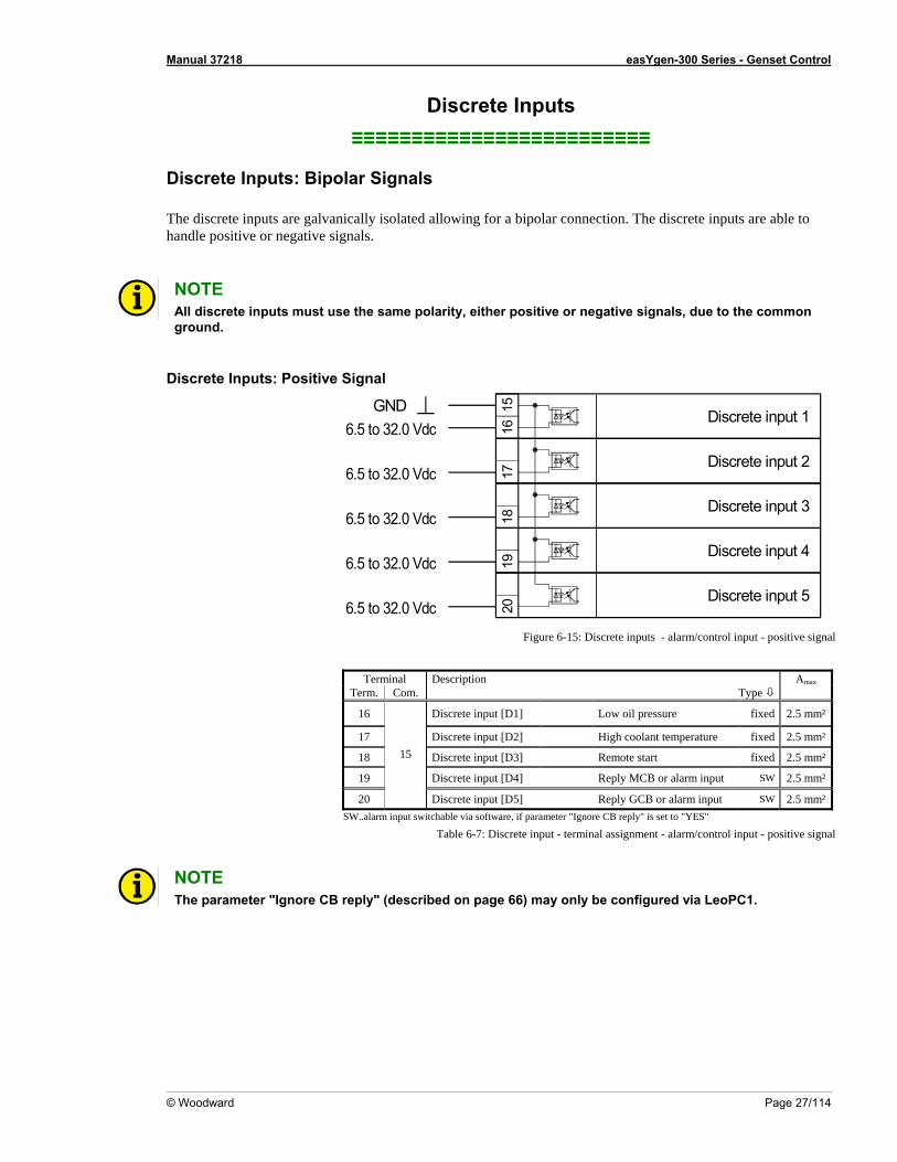
Discrete Inputs: Bipolar Signals The discrete inputs are galvanically isolated allowing for a bipolar connection. The discrete inputs are able to handle positive or negative signals. NOTE All discrete inputs must use the same polarity, either positive or negative signals, due to the common ground.
Discrete Inputs: Positive Signal
1617
Discrete input 115
6.5 to 32 d.0 V cGND
Discrete input 2
Discrete input 318
Discrete input 4
19
Discrete input 5
20
6. 32 d
gnal
5 to .0 V c
6.5 to 32.0 Vdc
6.5 to 32.0 Vdc
6.5 to 32.0 VdcFigure 6-15: Discrete inputs - alarm/control input - positive si
Terminal Description Amax
Term. Com. Type
16 Discrete input [D1] Low oil pressure fixed 2.5 mm²
17 Discrete input [D2] High coolant temperature fixed 2.5 mm²
18 Discrete input [D3] Remote start fixed 2.5 mm²
19 Discrete input [D4] Reply MCB or alarm input SW 2.5 mm²
20 Discrete input [D5] Reply GCB or alarm input SW 2.5 mm²
15
SW..alarm input switchable via software, if parameter "Ignore CB reply" is set to "YES"
Table 6-7: Discrete input - terminal assignment - alarm/control input - positive signal
NOTE The parameter "Ignore CB reply" (described on page 6
6) may only be configured via LeoPC1.
Manual 37218 easYgen-300 Series - Genset Control
Page 28/114 © Woodward
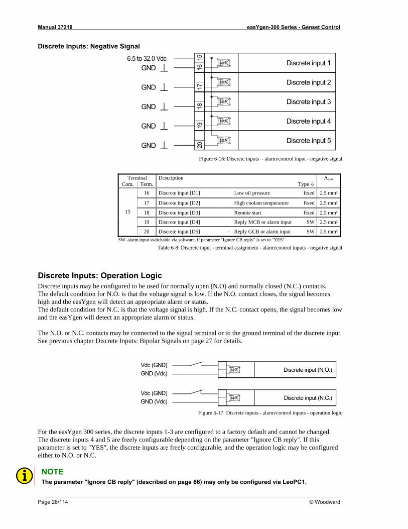
Discrete Inputs: Negative Signal
1617
Discrete input 1156.5 to 32.0 VdcGND
Discrete input 2
Discrete input 3
18
Discrete input 4
19
Discrete input 5
20
GND
GND
GND
GND
Figure 6-16: Discrete inputs - alarm/control input - negative signal
minTer al Description Amax
C Term. Tom. ype 16 Discrete input [D1] Low oil pressure fixed 2.5 mm²
17 Discrete input [D2] High coolant temperature fixed 2.5 mm²
18 fixed 2.5 mm²Discrete input [D3] Remote start
19 Discrete input [D4] CB or alarm input SWReply M 2.5 mm²
15
20 Discrete input [D5] SW 2.5 mm²- Reply GCB or alarm input SW rm input swit parameter "Ignore CB reply
Table 6-8: Discrete input - terminal assignment - alarm/control inputs - negative signal
Discrete Inputs: Opera n L iDiscrete inputs may be configured to be used for normally open (N.O) and normally closed (N.C.) cont cts. The default condition for N.O. is that th oltage signal is low. If the N.O. cohigh and the easYgen will detect an appropriate alarm or status.
he default condition for N.C. is that the voltage signal is high. If the N.C. contact opens, the signal becomes low
r N.C. contacts may be connected to the signal terminal or to the ground terminal of the discrete input. See previous chapter Discrete Inputs: Bipolar Signals on page 27 for details.
..ala chable via software, if " is set to "YES"
tio og c a
e v ntact closes, the signal becomes
Tand the easYgen will detect an appropriate alarm or status. The N.O. o
Discrete input (N.O.)Vdc (GND)GND (Vdc)
Discrete input (N.C.)Vdc (GND)GND (Vdc)
Figure 6-17: Discrete i l inputs - operation logic
F series, th screte inputs 1-3 are configured to a factory default and cannot be changed. The di y configurable depending on the paramparameter is set to "YES", the discrete inputs are freely configurable, aneither to N.O. or N.C.
nputs - alarm/contro
or the easYgen 300 screte inputs 4 and 5 are freel
e dieter "Ignore CB reply". If this
d the operation logic may be configured
NOTE The parameter "Ignore CB reply" (described on page 66) may only be configured via LeoPC1.
Manual 37218 easYgen-300 Series - Genset Control
© Woodward Page 29/114
Relay≡≡≡≡≡≡≡≡≡≡≡≡≡≡≡≡≡≡≡≡≡≡≡≡≡
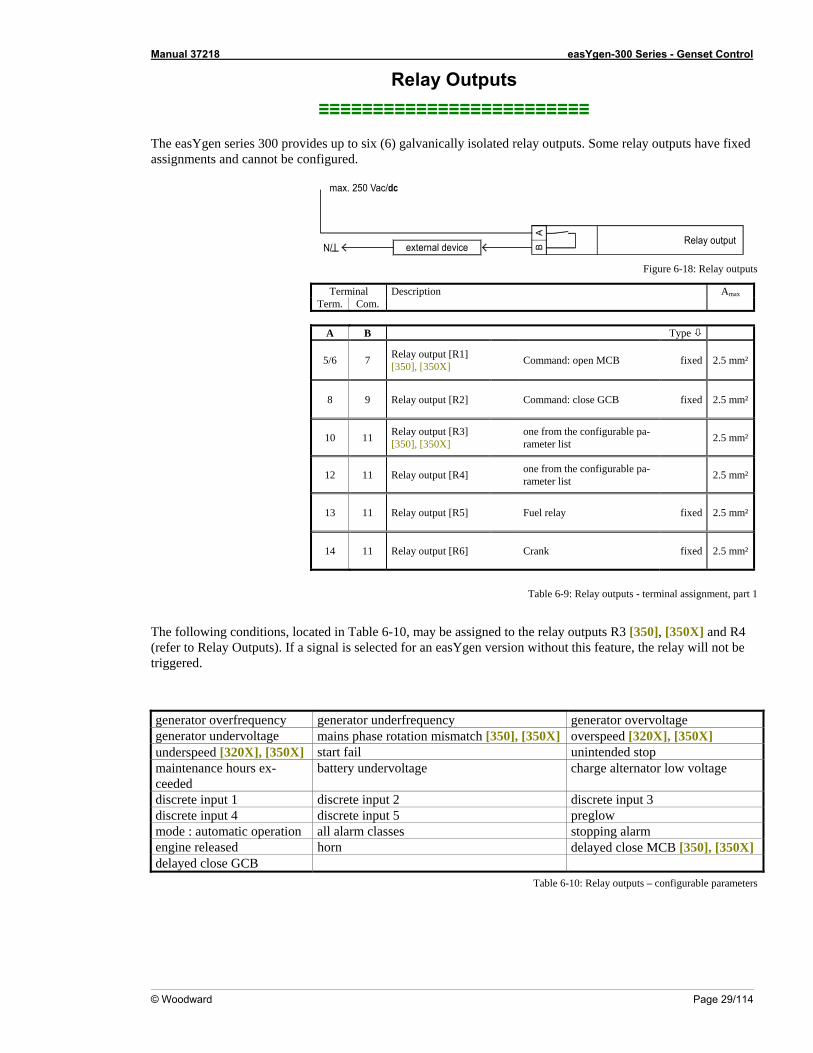
The easYgen series 300 provides up to six (6) galvanically isolated relay outputs. Some relay outputs have fixed
d cannot be configured.
Outputs
assignments an
AB
Relay outputexternal device
max. 250 Vac/dc
N/ Figure 6-18: Relay outputs
Terminal Description Amax
Term. Com.
A B Type
5/6 7 Relay output [R1] [350], [350X] Command: open MCB fixed 2.5 mm²
8 9 Relay output [R2] Command: close GCB fixed 2.5 mm²
10 11 Relay output [R3] [350], [350X]
one from the configurable pa-rameter list 2.5 mm²
12 11 Relay output [R4] one from the configurable pa-rameter list 2.5 mm²
13 11 Relay output [R5] Fuel r fixed 2.5 mm²elay
14 11 Relay output [R6] m² Crank fixed 2.5 m
Table 6-9: Relay out rminal assignment, part 1
The following conditions, lo ted in Table 6-10, may be n R (refer to Relay Outputs). If a signal is selected for an ea v t e relay will not be triggered.
generator verfr uenc g or underfrequ tage
puts - te
ca assig ed to the relay outputs 3 [350], [350X] and R4sYgen ersion without this fea ure, th
o eq y enerat ency generator overvolgenerator undervoltage m ins phase rotation m X X], [350X] a ismatch [350], [350 ] overspeed [320underspeed [320X], [350X] start fail unintended stop maintenance hours ex- battery undervoltage charge alternator low voltage ceeded discrete input 1 discrete input 2 discrete input 3 discrete input 4 discrete input 5 preglow mode : automatic operation all alarm classes stopping alarm engine released horn delayed close MCB [350], [350X] delayed close GCB
Table 6-10: Relay outputs – configurable parameters
Manual 37218 easYgen-300 Series - Genset Control
Page 30/114 © Woodward
Interfaces ≡≡≡≡≡≡≡≡≡≡≡≡≡≡≡≡≡≡≡≡≡≡≡≡≡
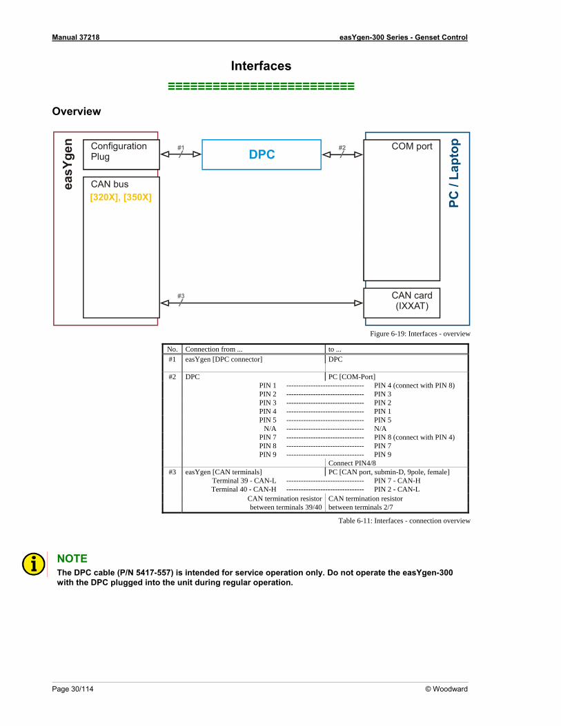
Overview
PC /
ptop
La
#1 #2
#3
ConfigurationPlug
CAN buseasY
gen
DPC
[320X], [350X]
Figure 6-19: Interfaces - overview
No. Connection from ... to ...
COM port
CAN card(IXXAT)
#1 easYgen [DPC connector] DPC #2 DPC PC [COM-Port] PIN 1 -------------------------------- PIN 4 (connect with PIN 8) PIN 2 -------------------------------- PIN 3 PIN 3 -------------------------------- PIN 2 PIN 4 -------------------------------- PIN 1 PIN 5 -------------------------------- PIN 5 N/A -------------------------------- N/A PIN 7 -------------------------------- PIN 8 (connect with PIN 4) PIN 8 -------------------------------- PIN 7 PIN 9 -------------------------------- PIN 9 Connect PIN4/8 #3 easYgen [CAN terminals] PC [CAN port, submin-D, 9pole, female] Terminal 39 - CAN-L -------------------------------- PIN 7 - CAN-H Terminal 40 - CAN-H -------------------------------- PIN 2 - CAN-L
CAN termination resistorbetween terminals 39/40
CAN termination resistor between terminals 2/7
Table 6-11: Interfaces - connection overview
NOTE The DP C cable (P/N 5417-557) is intended for service operation only. Do not operate the easYgen-300 with the DPC plugged into the unit during regular operation.
Manual 37218 easYgen-300 Series - Genset Control
© Woodward Page 31/114
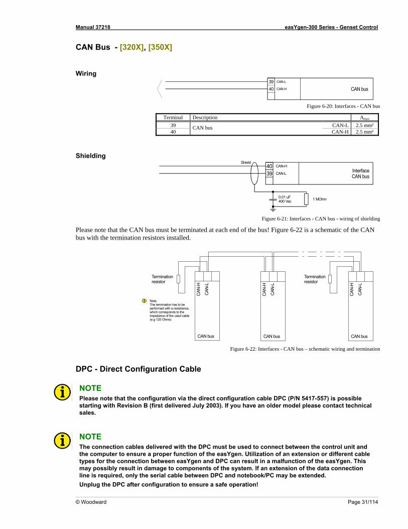
CAN Bus - [320X], [350X]
Wiring
CAN busCAN-L
40 CAN-H
39
Figure 6-20: Interfaces - CAN bus
Terminal Description Amax
39 CAN-L 2.5 mm² 40
CAN bus CAN-H 2.5 mm²
Shielding
InterfaceCAN bus
CAN-H
CAN-L
Shield
1 MOhm0.01 uF400 Vac
4039
Figure 6-21: Interfaces - CAN bus - wiring of shielding
Please note that the CAN bus must be terminated at each end of the bus! Figure 6-22 is a schematic of the CAN bus with the termination resistors installed.
CAN
-L
CAN-
H
CAN-
L
CAN
-H
CAN
-L
CAN-
H
Terminationresistor
Note:The termination has to be performed with a resisitance,which corresponds to the
CAN bus
impedance of the used cable (e.g 120 Ohms)
CAN bus CAN bus
Terminationresistor
Figure 6-22: Interfaces - CAN bus – schematic wiring and termination
DPC - Direct Configuration Cable NOTE Please note that the configuration via the direct configuration cable DPC (P/N 5417-557) is possible
w t R B (first delivered July 2003). If you have an older model please contact technical sales.
starting i h evision
NOTE T e connection the DPC must be used to connect between the control unit and the computer ttypes for the comay possibly r onnection line is required, only the serial cable between DPC and notebook/PC may be extended. Unplug the DPC after configuration to ensure a safe operation!
h cables delivered witho ensure a proper function of the easYgen. Utilization of an extension or different cable nnection between easYgen and DPC can result in a malfunction of the easYgen. This
esult in damage to components of the system. If an extension of the data c
Manual 37218 easYgen-300 Series - Genset Control
Page 32/114 © Woodward
Chapter 7. Operation and Navigation
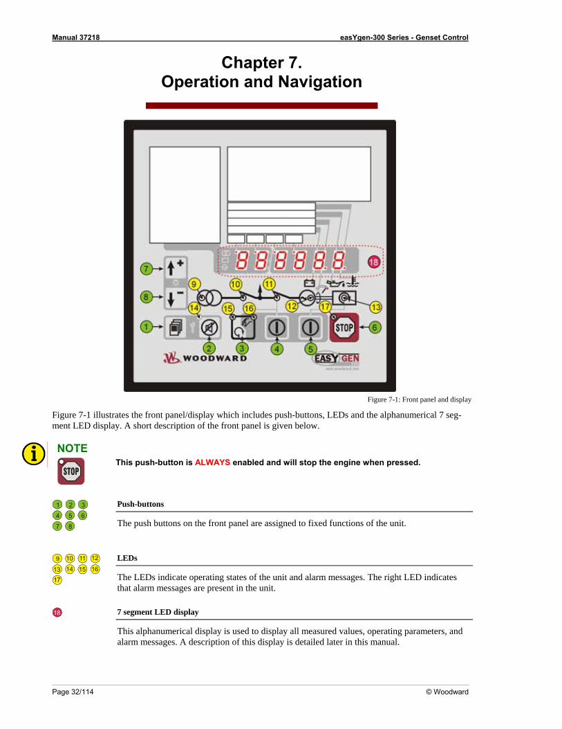
Figure 7-1: Front panel and display
Fm NO
igure 7-1 illustrates the front panel/display which includes push-buttons, LEDs and the alphanumerical 7 seg- LED display. A short description of the front panel is given below. ent
TE This push-button is ALWAYS enabled and will stop the engine when pressed.
Push-buttons 1 2 3 4 5 6 The push buttons on the front panel are assigned to fixed functions of the unit. 7 8
9 10 11 12
13 14 15 16 17
LEDs
The LEDs indicate operating states of the unit and alarm messages. The right LED indicates that alarm messages are present in the unit.
18 7 segment LED display
This alphanumerical display is used to display all measured values, operating parameters, and alarm messages. A description of this display is detailed later in this manual.
Manual 37218 easYgen-300 Series - Genset Control
© Woodward Page 33/114
Operation and Display
:
≡≡≡≡≡≡≡≡≡≡≡≡≡≡≡≡≡≡≡≡≡≡≡≡≡
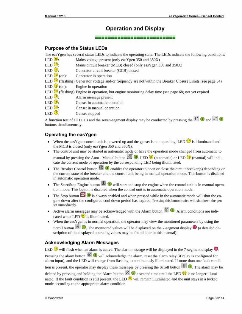
Purpose of the Status LEDs The easYgen has several status LEDs to indicate the operating state. The LEDs indicate the following conditionsLED 9 : Mains voltage present (only easYgen 350 and 350X) LED 10 : Mains circuit breaker (MCB) closed (only ea gen 350 and 350X) LED
sY11 : enerator circ it reaker (GCB) closed G u b
LED 12 (on): Generator in operation LED 12 (flashing): Generator voltage and/or frequency are not within the Breaker Closure Limits (see page 54) LED 13 (on): Engine in operation LED 13 (flashing): Engine in operation, but engine monitoring delay time (see page 68) not yet expired LED 14 : Alarm message present LED 15 : Genset in automatic operation
ED 16 : Genset in manual operation LLED 17 : Genset stopped
A function test of all LEDs and the seven-segment display may be conducted by pressing the 7 and 8 buttons simultaneously.
Operating the easYgen • When the easYgen control unit is powered up and the genset is not operating, LED 17 is illuminated and
the MCB is closed (only easYgen 350 and 350X). • The control unit may be started in automatic mode or have the operation mode changed from automatic to
manual by pressing the Auto - Manual button 3 . LED 15 (automatic) or LED 16 (manual) will indi-cate the current mode of operation by the corresponding LED being illuminated.
• The Breaker Control button 4 enables the operator to open or close the circuit breaker(s) dependingthe current state of the breaker and the control unit being in manual operation mode. This button is disabledin automatic operation mode.
The Start/Stop Engine bu
on
• tton 5 will start and stop the engine when the control unit is in manual opera-ation mode. tion mode. This button is disabled when the control unit is in automatic oper
6 is always enabled and when pressed while in the automatic mode will shut the enool down period has expired. Pressing this button twice will shutdo
• The Stop button -wn the gen-
• e acknowledged with the Alarm button
gine down after the configured cset immediately.
2Active alarm messages may b . Alarm conditions are indi-cated when LED 14 is illWh
uminated. • en the easYgen is in normal operation, the operator may view the monitored parameters by using the
Scroll button 1 yed on the 7. The monitored values will be displa -segment display 18 (a detailed de-ater in this manual). scription of the displayed operating values may be found l
Acknowledging Alarm Messages LED 14 will flash when an alarm is active. The alarm message will be displayed in the 7-segment display 18 .
Pressing the alarm button 2 will acknowledge the alarm, reset the alarm relay (if relay is configured for alarm input), and the LED will change from flashing to continuously illuminated. If more than one fault condi-
tion is present, the operator may display these messages by pressing the Scroll button 1 . The alarm may be
2deleted by pressing and holding the Alarm button a second time until the LED 14 is no longer illumi-nated. If the fault condition is still present, the LED 14 will remain illuminated and the unit stays in a locked mode according to the appropriate alarm condition.
Manual 37218 easYgen-300 Series - Genset Control
Page 34/114 © Woodward
Configuring the easYgen To enter the configuration mode, press the Scroll 1 and Alarm 2 buttons simultaneously. Pressing the
Scroll button 1 will display the various parameters that may be changed. The displayed values for the pa-
7 and 8rameters may be changed by pressing the buttons (a detailed description of the parameters be-e 64 of this manual). rator presses and holds these buttons, the rate of cha value
the parameter s been adjusted to the desired value, enter it into the contrgins on pag If the ope nge for the will increase. After
the Scroll button
ha ol unit by pressing
1 once. After a parameter has been changed and entered into the contro
may advance to the next parameters by pressing the Scroll button
l unit, the operator
1 a second time. To ex on
oll
it the configurati
mode, press the Scr 1 and Alarm 2 buttons simultaneously again.
Display of the Operating Values The easYgen-300 series control units are able to display various measured values during oper o
en model. You may advance through the single value displays using the S
ation depending n
the respective easYg croll button 1 .
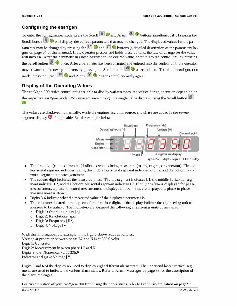
The values are displayed numerically, while the engineering unit, source, and phase are coded in the seven-segment display 18 if applicable. See the exam
ple below:
Figure 7-2: 6 digi p
ed from left) indicates what is being measured, (mains, engine, or g phorizontal segment indicates mains, the middle horizontal segment indicates engine, and
indicates generator. t indicates th measured phase. The top segment indicates L1, the middle2, and the bottom horizontal segment indicates L3. If only one line is dis e
measurement, a phase to neutral measurement is displayed. If two lines are displayed, a pmeasure ment is shown.
cate what the measured value of the displayed parameter is. he top left of the first four digits of the display indicate the eng f e indicators are assigned the following engineering units of me
urs [h] : Revolutions [rpm
equency [Hz] o Digit 4: Voltage [V]
ation, the example in the figure above reads as follows:
r between phase L2 and N is at 235.0 volts
Digit 2: Measurement between phase L2 and N merical value 235.0
Voltage [V]
Digits 5 and 6 of the display are used to display eight different alarm states. The upper and lowments are used to indicate the various alarm states. Refer to Alarm Messages on page 38 for th f the alarm messages. For customization of your easYgen-300 front using the paper strips, refer to Front Customization on page 97.
t 7 segment LED dis lay
• The first digit (count enerator). The tori-
the bottom ho
zontal segment• The second digi
ment indicates Le horizontal seg-
played for phashase to phase
• Digits 3-6 indi• The indicators located at t
measure to be utilized. Tho Digit 1: Operating ho
ineering unit oasure.
o Digit 2o Digit 3: Fr
]
With this informVoltage at generatoDigit 1: Generator
Digits 3 to 6: NuIndicator at digit 4:
er vertical seg-e description o
Manual 37218 easYgen-300 Series - Genset Control
© Woodward Page 35/114
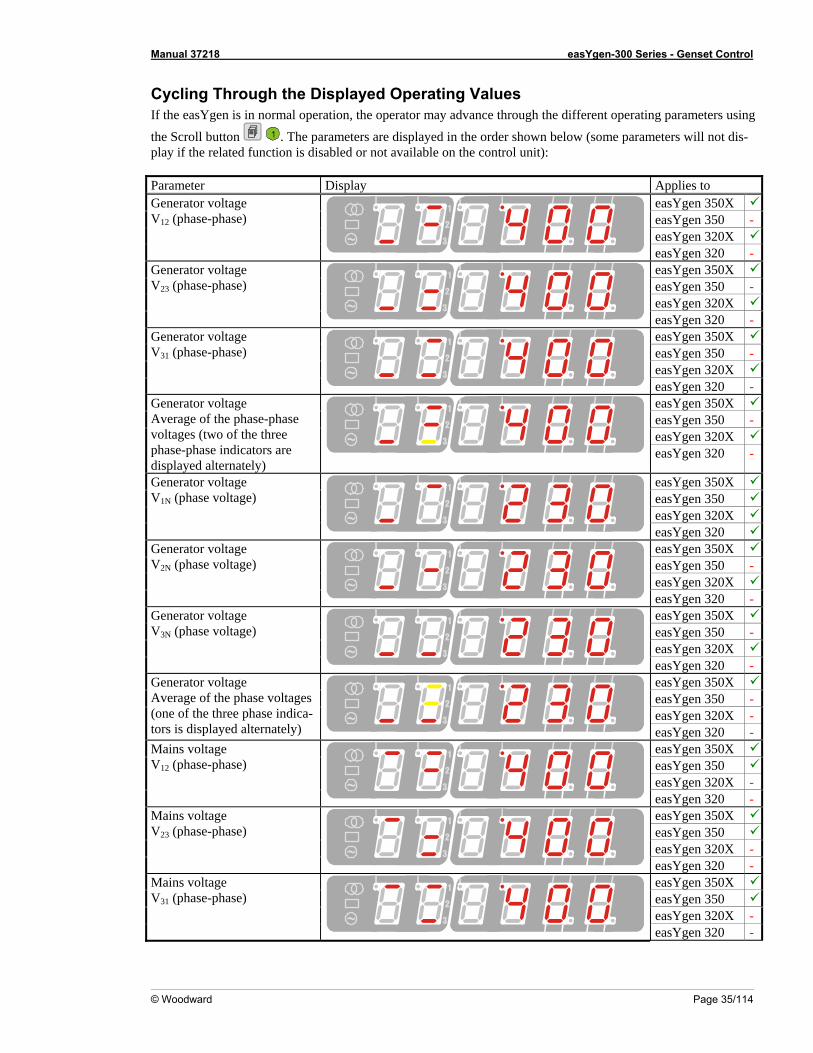
ough the Displayed Operating Values peration, the operator may advance through the different operatin sin
Cycling ThrIf the easYgen is in normal o
the Scroll button
g parameters u g
1 . The pplay if the related function is di
arameters are displayed in the order shown below (some paramsabled or not available on the control unit):
D splay
eters will not dis-
Parameter i Applies to
easYgen 350X easYgen 350 - easYgen 320X
Generator voltage V12 (phase-phase)
easYgen 320 - easYgen 350X easYgen 350 - easYgen 320X
Generator voltage V23 (phase-phase)
easYgen 320 - easYgen 350X easYgen 350 - easYgen 320X
Generator voltage V31 (phase-phase)
easYgen 320 - easYgen 350X easYgen 350 - easYgen 320X
Generator voltage Average of the phase-phase voltages (two of the three phase-phase indicators are displayed alternately)
easYgen 320 -
easYgen 350X easYgen 350 easYgen 320X
Generator voltage
V1N (phase voltage)
easYgen 320 easYgen 350X easYgen 350 - easYgen 320X
Generator voltage tage)
V2N (phase vol
easYgen 320 - easYgen 350X easYgen 350 - easYgen 320X
Generator voltage V3N (phase voltage)
easYgen 320 - easYgen 350X easYgen 350 - easYgen 320X -
Generator voltage Average of the phase voltages (one of the three phase indica-tors is displayed alternately) easYgen 320 -
easYgen 350X easYgen 350 easYgen 320X -
Mains voltage V (p12 hase-phase)
easYgen 320 - easYgen 350X easYgen 350 easYgen 320X -
Mains voltage
V23 (phase-phase)
easYgen 320 - easYgen 350X easYgen 350 easYgen 320X -
Mains voltage V (phase-phase) 31
easYgen 320 -
Manual 37218 easYgen-300 Series - Genset Control
Page 36/114 © Woodward
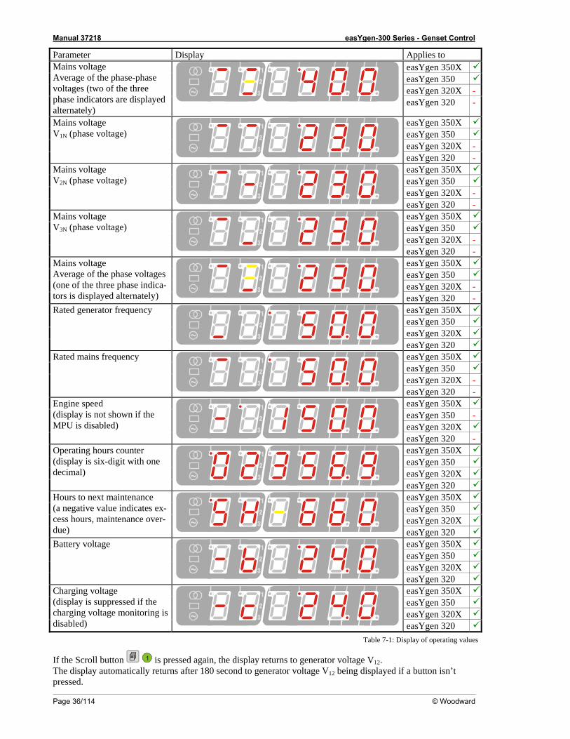
Applies to Parameter Display easYgen 350X easYgen 350 easYgen 320X -
Mains voltage Average of the phase-phase voltages (two of the three phase indicators are displayed alternately)
easYgen 320 -
easYgen 350X easYgen 350
Mains voltage
easYgen 320X -
V1N (phase voltage)
easYgen 320 - easYgen 350X easYgen 350 easYgen 320X -
M ge V
ains volta2N (phase voltage)
easYgen 320 - easYgen 350X easYgen 350 easYgen 320X
Mains voltage
-
V3N (phase voltage)
easYgen 320 - easYgen 350X easYgen 350 easYgen 320X
M
-
ains voltage Average of the phase voltages ( indica-tors is displayed alternately) one of the three phase
easYgen - 320 easYgen 350XeasYgen 350 easYgen 320X
Rated generator frequency
easYgen 320easYgen 350XeasYgen 350 easYgen - 320X
Rated mains frequency
easYgen - 320easYgen 350XeasYgen 350 - easYgen 320X
Engine speed ( n if the M U idis
Pplay is not show
s disabled) easYgen - 320easYgen 350XeasYgen 350 easYgen 320X
Operating hours counter ( one decimal)
gen
display is six-digit with
easY 320easYgen 350XeasYgen 350 easYgen X 320
Hours to next maintenance (a negative value indicates ex-cess hours, maintenance over-due) easYgen 320
easYgen 350XeasYgen 350 easYgen X 320
Battery voltage
easYgen 320easYgen 350XeasYgen 350 easYgen 320X
Charging voltage (charging voltage monitoring is disabled)
display is suppressed if the
easYgen 320 Table 7-1: D sp
If the Scroll button
i lay of operating values
1 is pressed again, the display returns to generator voltage V12. The display automatically returns after 180 second to generator voltage V12 being displayed if tonpressed.
a but isn’t
Manual 37218 easYgen-300 Series - Genset Control
© Woodward Page 37/114
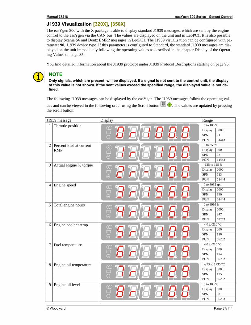
J1939 Visualization [320X], [350X] e X package is able to display standard J1939 messages, which are se ne
control to the easYgen via the CAN bus. The values are displayed on the unit and in LeoPC1. ble to display Scania S6 and Deutz EMR2 messages in LeoPC1. The J1939 visualization can be ure h pa-rameter 90, J1939 device type. If this parameter is configured to Standard, the standard J193 ge is-
mmediately fol wing the operating values as described in the chapter Displ perat-ing Values on page 35. You find detailed information about the J1939 protocol under J1939 Protocol Descriptions sta on .
The easYgen 300 with th n It is also
t by the engi possi
c9
onfig d witmessa s are d
played on the unit i lo ay of the O
rting page 95 NOTE Only signals, which are present, will be displayed. If a signal is not sent to the control unit, the display of this value is not shown. If the sent values exceed the specified range, the displayed is -
The following J1939 messages can be displayed by the easYgen. The J1939 messages follow t era val-
he following order using the Scroll button
value not de
fined.
he op ting
ues and can be viewed in t 1 . The values are updat ng
J1939 message Display e
ed by pressithe scroll button.
Rang0 to 100 %
Display 000.0 SPN 91
1 Throttle position
PGN 61443 0 to 250 %
Display 000 SPN 92
2 Percent load at current RMP
PGN 61443 -125 to 125 %
Display 0000 SPN 513
3 Actual engine % torque
4 PGN 61440 to 8032 rpm
Display 0000 SPN 190
4 Engine speed
PGN 61444 0 to 9999 h
Display 0000 SPN 247
5 Total engine hours
PGN 65253 -40 to 210 °C
Display 000 SPN 110
6 Engine coolant temp
PGN 65262 -40 to 210 °C
Display 000 SPN 174
7 Fuel temperature
PGN 65262 -273 to 1735 °C
Display 0000 SPN 175
8 Engine oil temperature
PGN 65262 0 to 100 %
Display 000 SPN 98
9 Engine oil level
PGN 65263
Manual 37218 easYgen-300 Series - Genset Control
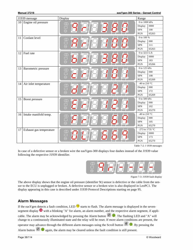
J1939 message Display Range 0 to 1000 kPa
Display 0000 SPN 100
10 Engine oil pressure
PGN 65263 0 to 100 %
Display 000 SPN 111
11 Coolant level
PGN 65263 0 to 3213 L/h
Display 0000 SPN 183
12 Fuel rate
PGN 65266 0 to 125 kPa
Display 000 SPN 108
Page 38/114 © Woodward
13 Barometric pressure
PGN 65269 -40 to 210 °C
Display 000 SPN 172
14 Air inlet temperature
PGN 65269 0 to 500 kPa
Display 000 15 Boost pressure
SPN 102
PGN 65270 -40 to 210 °C
Display 000 SPN 105
16 Intake manifold temp.
PGN 65270 -273 to 1735 °C
Display 0000 SPN 173
17 Exh temperataust gas ure
PGN 65270
Table 7-2: J 1 ssag
en wire the easYgen-300 displays four dashes instead of the J193follo spective J1939 identifier.
939 me es
In case of a defective swing the re
sor or a broken 9 value
Figure 7-3: J1939 isp
ws e oil pressure (identifier 9r) sensor is defective or the cable from nsor t U is unplugged or broken. A defective sensor or a broken wire is also displayed in LeoPC e display appearing in this case is described under J1939 Protocol Descriptions starting on page 95.
Alarm Messages If the easYgen detects a fault condition, LED
fault d lay
The above display shoo the EC
that the engin the se -1. Th
14 starts to flash. The alarm message is displayed in the segment display
seven- 18 with a blinking "A" for alarm, an alarm number, and the respective alarm segment, if appli-
e by pressing the Alarm button 2cable. The alarm may b acknowledged . The flashing LED and "Achange to a continuously illuminated state and the relay will be reset. If more alarm conditions are present, the
operator may advance through the different alarm messages using the Scroll button
" will
1 . By pressing the
Alarm button 2 again, the alarm may cleared unless the fault condition is still present. be
Manual 37218 easYgen-300 Series - Genset Control
© Woodward Page 39/114
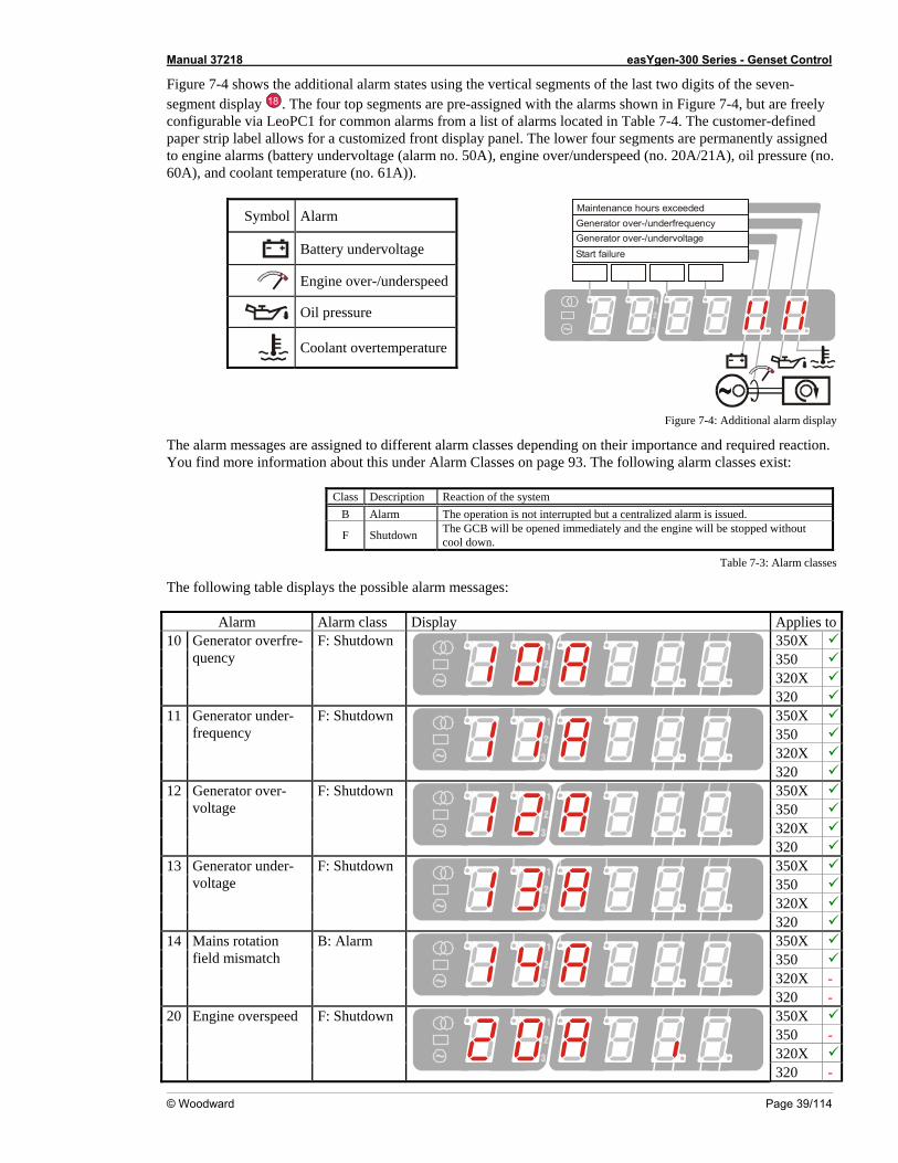
Figure 7-4 shows t e additional alarm sta the vertical segments of the last two digits of the seven-egm di
h tes using s ent splay 18 . The four top segmen are pre-assigned with the alarms shown in Figure 7-4, but are freelyconfigurable via LeoPC1 for common alarms from a list of alarms located in Table 7-4. The customer-defined paper strip la ws for a customized front display panel. The lower four segments are permanently ned
s (battery alarm no. 50A), engine over/underspeed (no. 20A/21A), oil pr nant temperat
Symbol Alarm
ts
bel allo assig to e60A), and cool
ngine alarm undervoltage (ure (no. 61A)).
essure ( o.
Start failureGenerator over-/undervoltageGenerator over-/underfrequencyMaintenance hours exceeded
Ba tage ttery undervol
Engine over-/underspeed
Oil pressure
Coolant overtemperature
Figure 7-4: Additional pl
The alarm messages are assigned to different alarm classes depending on their importance and required reactionmatio s under Alarm Classes on page 93. The following alarm classes ex
Class Description Reaction of the system
alarm dis ay
. You find more infor n about thi ist:
B Alarm The operation is not interrupted but a centralized alarm is issued.
F Shutdown The GCB will be opened immediately and the engine will be stopped cool down. without
Table 7-3: ass
The following table displays the possible alarm messages:
Display s
Alarm cl es
Alarm Alarm class Applie to
350X 350 320X
10 Generator overfre-quency
F: Shutdown
320 350X 350 320X
11 Generatfrequency
or under- F: Shutdown
320 350X 350 320X
12 Generatvoltage
or over- F: Shutdown
320 350X 350 320X
13 Generator under-voltage
down F: Shut
320 350X 350
14 Mains rotation ismatch
B: Alarm
320X -
field m
320 - 350X 350 - 320X
20 Engine overspeed F: Shutdown
320 -
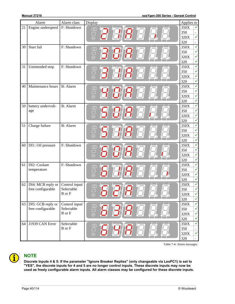
Manual 37218 easYgen-300 Series - Genset Control
Page 40/114 © Woodward
Alarm Alarm class Display Applies to350X 350 -
21 Engine underspeed F: Shutd
320X
own
320 - 350X 350 320X
30 Start fail F: Shutdown
320 350X 350 320X
31 Unintended stop n F: Shutdow
320 350X 350 320X
40 Maintenance hours B: Alarm
320 350X 350 320X
50 battery underage
volt- B: Alarm
320 350X 350 320X
51 Charge failure B: Alarm
320 350X 350 320X
60 DI1: Oil pressure F: Shutdown
320 350X 350 320X
61 DI2: Coolant temperature
F: Shutdown
320 350X 350 320X
62 DI4: MCB reply free configurable
B or F
or
Control input/Selectable
320 350X 350 320X
63 DI5: GCB refree co
ply onfigurable
B or F
r
Control input/Selectable
320 350X 350 - 320X
64 J1939 CAN Error SelectableB or F
320 -
Table 7-4: Al agarm mess es
NOTE
meter "Ignore Breaker Replies" (only changeable via LeoPC1) is set to Y ete d 5 are no longer control inputs. These discrete inputs may n e
ly configurable alarm inputs. All alarm classes may be configured for these discrete inputs.
Di"us
screte Inputs 4 &ES", the discred as free
5: If the para inputs for 4 an ow b
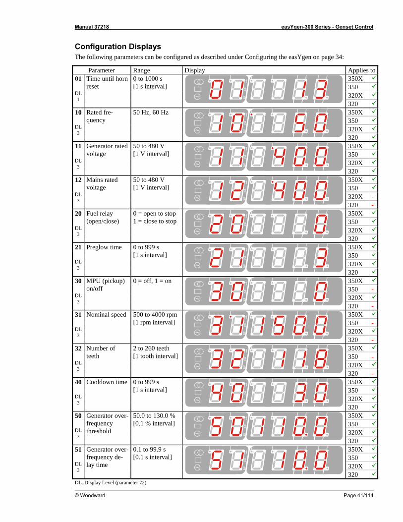
Manual 37218 easYgen-300 Series - Genset Control
© Woodward Page 41/114
on Dscribed under Configuring the easYgen on page 34:
Parameter Range Display
CoThe
nfigurati following param
isplays eters can be configured as de
Applies to350X 350 320X
01
DL 1
Time until hornreset
0 to 1000 s [1 s interval]
320 350X 350 320X
10
DL 3
Rated fre-quency
50 Hz, 60 Hz
320 350X 350 320X
11
DL 3
Generator rvoltage
ated 50 to 480 V [1 V interval]
320 350X 350 320X -
12
DL 3
Mains ratedvoltage
50 to 480 V [1 V interval]
320 - 350X 350 320X
20
DL 3
Fuel relay (open/close)
0 = open to st1 = close to stop
op
320 350X 350 320X
21
DL 3
Preglow time 0 to 999 s [1 s interval]
320 350X 350 - 320X
30
DL 3
MPU (pickupon/off
) 0 = off, 1 = on
320 - 350X 350 - 320X
31
DL 3
Nominal speed m500 to 4000 rp[1 rpm interval]
320 - 350X 350 - 320X
32
DL 3
Number of teeth
2 to 260 teeth [1 tooth interval]
320 - 350X 350 320X
40
DL 3
Cooldown time 0 to 999 s [1 s interval]
320 350X 350 320X
50
DL 3
Generator ovefrequency threshold
r- 50.0 to 130.0 % [0.1 % interval]
320 350X 350 320X
51 Generator over- 0.1 to 99.9 s
DL 3
frequency de-lay time
[0.1 s interval]
320 DL..Display Level (parameter 72)
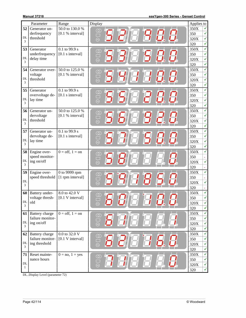
Manual 37218 easYgen-300 Series - Genset Control
Page 42/114 © Woodward
Parameter Range Display Applies to350X 350 320X
52
DL 3
Generator un-derfrequency threshold
[0.1 % interval] 50.0 to 130.0 %
320 350X 350 320X
53
DL 3
Generator underfrequency delay time
0.1 to 99.9 s[0.1 s interval]
320 350X 350 320X
54
DL 3
Generator ovvoltage thres
er-
hold
50.0 to 125.0 % [0.1 % interval]
320 350X 350 320X
55
DL 3
Generator overvoltage de-lay time
0.1 to 99.9 s [0.1 s interval]
320 350X 350 320X
56
DL 3
Generator un-dervoltage threshold
50.0 to 125.0 %[0.1 % interval]
320 350X 350 320X
57
DL 3
Generator un-dervoltage de-lay time
0.1 to 99.9 s [0.1 s interval]
320 350X 350 - 320X
58
DL 3
Engine over-speed moniing on/off
tor-0 = off, 1 = on
320 - 350X 350 - 320X
59
DL 3
Engine ovespeed thresho
r-ld
0 to 9999 rpm [1 rpm interval]
320 - 350X 350 320X
60
DL 3
Battery under-voltage thresh-old
.0 V val]
8.0 to 42[0.1 V inter
320 350X 350 320X
61
DL 3
Battery chafailure monitor-
rge
ing on/off
= on 0 = off, 1
320 350X 350 320X
62
DL 3
Battery charge failure monitor-ing threshold
0 V 0.0 to 32.[0.1 V interval]
320 350X 350 320X
71
DL 1
Reset mainte-nance hours
= yes 0 = no, 1
320 DL..Display Level (parameter 72)
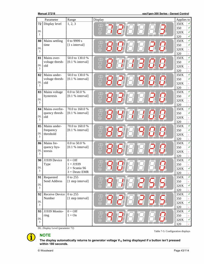
Manual 37218 easYgen-300 Series - Genset Control
© Woodward Page 43/114
Parameter Range Disp Applies tolay 350X 350 320X
72
DL 1
Display level 1, 2, 3
320 350X 350 320X -
80
DL 3
Mains settling time
0 to 9999 s [1 s interval]
320 - 350X 350 320X -
81 L
Mains over-voltage thresh-old
50.0 to 1[0.1 % in
30.0 % terval]
D3
320 - 350X 350 320X -
82
Mains under-voltage thresh-
50.0 to[0.1 % interval]
DL old 3
130.0 %
320 - 350X 350 320X -
83
Mains hysteresis [
DL 3
voltage 0.0 to 50.0 % 0.1 % interval]
320 - 350X 350 320X -
84 L
Mains oquency thresh-old
[D3
verfre- 70.0 to 160.0 % 0.1 % interval]
320 - 350X 350 320X -
85 Mains
under-frequethreshold
70.0 to 160.0 %
DL 3
ncy [0.1 % interval]
320 - 350X 350 320X -
86 L
Mains fre-quencteresis
0.0
D3
y hys- [0.1 % interval] to 50.0 %
320 - 350X 350 - 320X
90 J1939 De Type
DL
vice 0 = Off
3 = Deut3
1 = J1939 2 = Scania S6
z EMR 320 - 350X 350 - 320X
91 L
3
RequestSend A
D
ed ddress
0 to 255 [1 step interval]
320 - 350X 350 - 320X
92
Receive Device 0 to 255 Number [1 step interval]
DL3
320 - 350X 350 - 320X
93
DL 3
J1939 Monito-ring
0 = Off 1 = On
320 - DL..Display Level (parameter 72) Table 7-5: Configuration displays
NOTE The display automatically returns to generator voltage V12 being displayed if a button isn’t pressed
within 180 seconds.
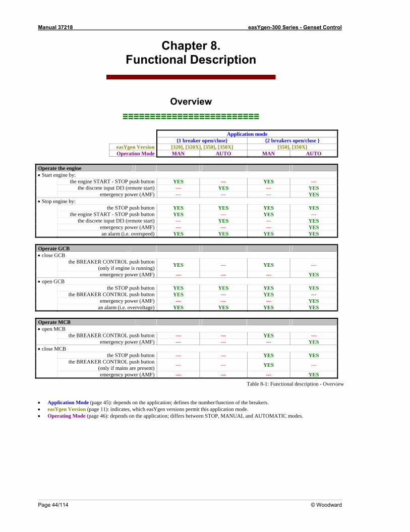
Manual 37218 easYgen-300 Series - Genset Control
Page 44/114 © Woodward
Chapter 8. Functional Description
Overview ≡≡≡≡≡≡≡≡≡≡≡≡≡≡≡≡≡≡≡≡≡≡≡≡≡
tion mode Applica n/close 1 breaker open/close 2 breakers ope ] easYgen Version [320], [320X], [350], [350X] [350], [350X MAN AUTO MAN AUTO Operation Mode Operate the engine • Start engine by: the engine START - STOP push button YES --- YES --- the discrete input DI3 (remote start) --- YES --- YES emergency power (AMF) --- --- --- YES • Stop engine by: S YES YES the STOP push button YES YE --- YES --- the engine START - STOP push button YES --- YES the discrete input DI3 (remote start) --- YES YES emergency power (AMF) --- --- --- YES an alarm (i.e. overspeed) YES YES YES Operate GCB • close GCB
YES --- the BREAKER CONTROL push button (only if engine is running) YES ---
emergency power (AMF) --- --- --- YES • open GCB the STOP push button YES YES YES YES the BREAKER CONTROL push button YES --- YES --- emergency power (AMF) --- --- --- YES an alarm (i.e. overvoltage) YES YES YES YES Operate MCB • open MCB the BREAKER CONTROL push button --- --- YES --- emergency power (AMF) --- --- --- YES • close MCB the STOP push button --- --- YES YES
the BREAKER CONTROL push button (only if mains are present) --- --- YES ---
emergency power (AMF) --- --- --- YES
Table 8-1: Functional description - Overview
• Application Mode (page 45): depends on the application; defines the number/function of the breakers. • easYgen Version (page 11): indicates, which easYgen versions permit this application mode. • Operating Mode (page 46): depends on the application; differs between STOP, MANUAL and AUTOMATIC modes.
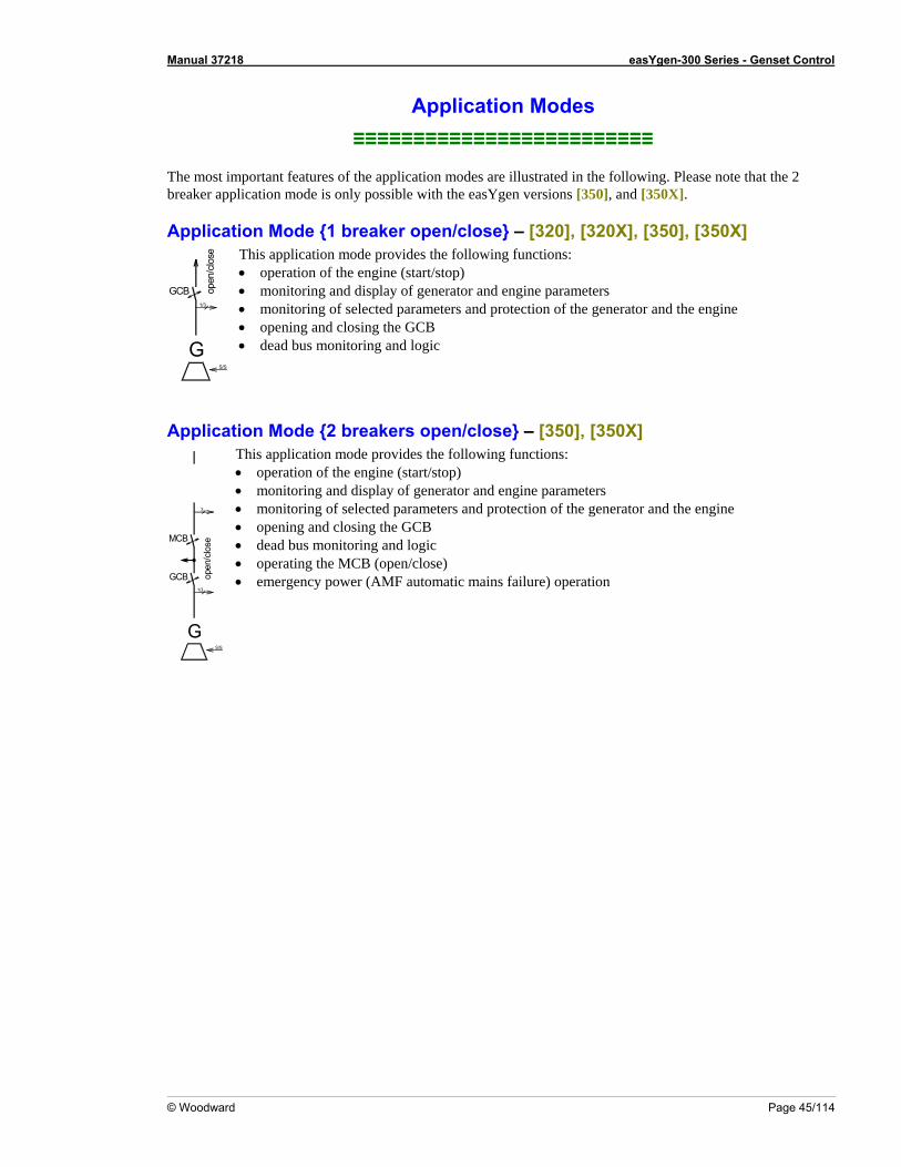
Manual 37218 easYgen-300 Series - Genset Control
© Woodward Page 45/114
Application Modes
e application modes are illustrated in the following. Please note that the 2
possible with the easYgen versions [350], and [350X].
– [320], [320X], [350], [350X]
≡≡≡≡≡≡≡≡≡≡≡≡≡≡≡≡≡≡≡≡≡≡≡≡≡ The most important features of th
reaker application mode is onlyb
Application Mode 1 breaker open/close
1/3
GS/S
GCB open
/clo
se This application mode provides the following functions: • operation of the engine (start/stop) • monitoring and display of generator and engine parameters • monitoring of selected parameters and protection o
f the generator and the engine • opening and closing the GCB • dead bus monitoring and logic
reakers open/close – [350], [350X] Application Mode 2 b
3
MCB
GCB1/3
GS/S
op • emergency
en/
ode provides the following functions: )
nd the engine
logic • operating the MCB (open/close)
power (AMF automatic mains failure) operation
close
• opening and closing the GCB • dead bus monitoring and
This application m• operation of the engine (start/stop• monitoring and display of generator and engine parameters • monitoring of selected parameters and protection of the generator a
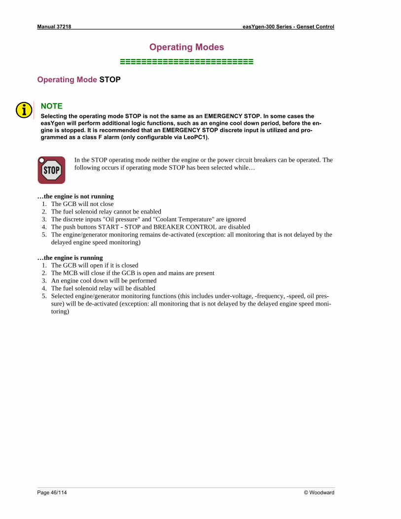
Manual 37218 easYgen-300 Series - Genset Control
Page 46/114 © Woodward
Operating Modes ≡≡≡≡≡≡≡≡≡≡≡≡≡≡≡≡≡≡≡≡≡≡≡≡≡
O
NOTE
perating Mode STOP
Selecting theasYgen wigine is stopgrammed s a class F alarm (only configurable via LeoPC1).
e operating mode STOP is not the same as an EMERGENCY STOP. In some cases the ll perform additional logic functions, such as an engine cool down period, before the en-ped. It is recommended that an EMERGENCY STOP discrete input is utilized and pro-
a
In the STOP operating mode neither the engine or the power circuit breakers can be operated. The following occurs if operating mode STOP has been se
lected while…
…the engine
1. The GCB will not close The fuel
3. The disc4. The pus5. The engi e
delayed
2. The MCB will c3. An engine cool d4. The fuel solenoid relay will be dis5. Selected engine/generator monitor y, -speed, oil pres-
sure) will b ti d gine speed moni-t
is not running
2. solenoid relay cannot be enabled rete inputs "Oil pressure" and "Coolant Temperature" are ignored h buttons START - STOP and BREAKER CONTROL are disabled ne/generator monitoring remains de-activated (exception: all monitoring that is not delayed by thengine speed monitoring)
…the engine is running 1. The GCB will open if it is closed
lose if the GCB isown will be perf
open and mains are present ormed abled ing functions (this includes under-voltage, -frequencon: all monitoring that is not delaye by the delayed ene de-activated (excep
g) orin
Manual 37218 easYgen-300 Series - Genset Control
© Woodward Page 47/114
Oper NO
ating Mode MANUAL
TE You find an overview about the butt play under Operation and
Nav
ons, LEDs and the seven-segment disigation on page 32.
In the MANUAL operating mode (AUTO - MANUAL button 3 ) the engine and the power circuit breakers are operated via n the BREAKER CONTROL butto 4 . The LED 16 in the upper right
n TO - Mcor er of the AU ANUAL button 3 indicates the manual operating mode. You c actions de on the application mode: an perform the following in the MANUAL operating mode pending
Appl ers ope
ication Mode 2 break n/close – [350], [350X]
The START - STOP button 5 Start ine (if the engine is stopped, LED 13 the eng is not illuminated)
p f the enSto the engine (i gine is running, LED 13 is illuminated)
The NTR BREAKER CO OL button 4 the MCB (if the control unit is in generaOpen the GCB and close tor operation (LEDs 11 and 12
are nd mainilluminated) a s are present, LED 9 is illuminated) the GCB (ifOpen se the MCB and clo the control unit is in mains operation (LEDs 9 and 10 are s running, LED illum ne iinated) and engi 13 is illuminated)
Deta t Bs in e e
onditions: • Generator is stopped – LED
iled opera ion with 2 C manual mode (mains ar pres nt)
Prec 12 is not illuminated • MCB is closed – LED 10 is illuminated • Mains are present – LED 9 is illuminated • Unit is in manual mode – LED 16 is illuminated Press the START - STOP button
Engine start sequence:Action START 5 Delay Preglow time the
Operation Crank relay ra (relay 6) is energized to engage the starter – LED
The relay will energize the glow plugs for the time configured inengine parameters (page 67) The fuel relay (relay 5) is energized to enable the fuel solenoid The c nk relay
Operation Fuel relay 12
illuminates and LED 13 starts flashing when generator speed has been detected
Delay Eng d ed in the engine re
ine delay time The engine monitoring is delaye until time configurparameters (page 68) expi s – LED 13 changes to steady illumination
GCB close sequence: Action Breaker control Pressin
after the time expires
g the BREAKER CONTROL button 4 Operation Open MCB The MCB open relay (relay 1) energizes to open the MCB – LED 10
goes out Delay Breaker delay The control unit waits for the breaker transfer time configured in the
breaker parameters (page 69) to expire Operation Close GCB The GCB close relay (relay 2) energizes to close the GCB – LED 11 il-
luminates
Manual 37218 easYgen-300 Series - Genset Control
Page 48/114 © Woodward
M control Press t
CB close sequence:
Action Breaker he BREAKER CONTROL button 4 on The GOperati Open GCB CB close relay (relay 2) de-energizes to open the GCB – LED 11
ut goes oy The co
breakeOperation Close MCB The M
LED
Delay Breaker dela ntrol unit waits for the breaker transfer time configured in the r parameters (page 69) to expire CB open relay (relay 2) de-energizes to close the MCB –
10 illuminates Stop sequ
STOP:
Action STOP Press t
ence via START -
he START - STOP button 5 Operation Open GCB The G e the GCB – LED CB close relay (relay 2) de-energizes to op n 11
goes oThe en to
ut gine s ps – LEDs Operation Engine stop 12 and 13 go out
Action Breaker control Pressing the BREAKER CONTROL button 4 CB open relay (relay 1) de-energizes to close the MCB – Operation Close MCB The M
LED 10 illuminates Stop sequence via STOP one
Press ttime:
Action STOP he STOP button 6 once Operation Open GCB The GCB close relay (relay 2) de-energizes to open the GCB – LED 11
ut
goes oelay Breaker delay
breaker parameters (page 69) to expire B open relay (relay 1) de-energizes to close the MCB –
LED
D The control unit waits for the breaker transfer time configured in the
Operation Close MCB The MC10 illuminates
Delay Cool down time The coparam xpire The en
ntrol unit waits for the cool down time configured in the engine eters (page 68) to e
Operation Engine stop gine stops – LEDs 12 and 13 go out Stop seque o
Action STOP Press t
nce via STOP twtimes:
he STOP button 6 twice O close relay (relay 2) de-energizes to open the GCB – LED peration Open GCB The GCB 11
goes oy The co
breaker param 69) to expire on The M
LED
ut Delay Breaker dela ntrol unit waits for the breaker transfer time configured in the
eters (pageOperati Close MCB CB open relay (relay 1) de-energizes to close the MCB –
10 illuminates Operation Engine stop The engine stops immediately without a cool down period – LEDs 12
and 13 go out
l mode (mains are Detailed operation with 2 CBs in manua not present) - [350], [350X]
Preconditions: • Generator is stopped – LED 12 o minated is n t illu • MCB is closed – LED 10 is illuminated • Mains are not present – LED 9 is not illuminated
t is in m nual mode• Uni a – LED 16 is illuminated
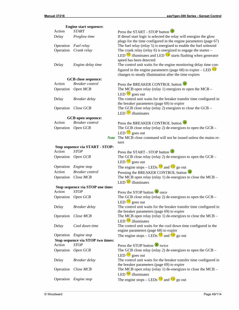
Manual 37218 easYgen-300 Series - Genset Control
© Woodward Page 49/114
Action START Press the START - STOP button Engine start sequence:
5 Delay If diesel start logic is selected the relay will energize the glow
e gine parameters (page 67) Operati ed to enable the fuel solenoid Operation Crank relay The crank relay (relay 6) is energized to engage the starter –
Preglow time plugs for the tim configured in the en
on Fuel relay The fuel relay (relay 5) is energiz
LED 12 illuminates and LED 13 starts flashing when generator d as been detected
Delay u engine monitoring delay time con-h
spee hEngine delay time The control nit waits for the
figured in t e engine parameters (page 68) to expire – LED 13 chan steady illumination after the time expires
e BREAKER CONTROL button
ges toGCB close sequence:
Action Breaker control Press th 4 Operation Open MC e MCB – B The MCB open relay (relay 1) energizes to open th
LED 10 goes out e control unit waits for the breaker transfer time configured in Delay Th
) expire on
Breaker delay the breaker parameters (page 69 to
Operati Close GCB The GCB close relay (relay 2) energizes to close the GCB – LED 11 illuminates
GCB open sequence: ol
Action Breaker contr Press the BREAKER CONTROL button 4
The GCB close relay (relay 2) de-energizes to open the GCB –LED
Operation Open GCB 11 goes out
Note e-
Stop sequence via START - STOP: Action Press the START - STOP button
The MCB close command will not be issued unless the mains rturn
STOP 5 Operation zes to open the GCB – Open GCB The GCB close relay (relay 2) de-energi
LED 11 goes out The engine stops – Operation Engine stop LEDs 12 and 13 go out
Action ttonBreaker control Pressing the BREAKER CONTROL bu 4 Operation Close MCB The MCB open relay (relay 1) de-energizes to close the MCB
LED –
10 illuminates Stop sequence via STOP one time:
Act Press the STOP button ion STOP 6 once n e nergizes to open the GCB – Operatio Open GCB The GCB close relay (relay 2) d -e
LED 11 goes out The control unit waits for the breaker transfer time configuredthe b eaker param
Delay Breaker delay in
l s to close the MCB – r eters (page 69) to expire
The MCB open relay (re ay 1) de-energizeOperation Close MCB LED 10 illuminates
Delay Cool down time e The control unit waits for the cool down time configured in thengine parameters (page 68) to expire
Operation Engine stop The engine stops – LEDs 12 and 13 go out Stop seque o times:nce via STOP tw
Action STOP Press the STOP button 6 twiceThe GCB close relay (re y 2) de-energize
la s to open the GCB –
LED Operation Open GCB
11 goes out lay reaker transfer time configured in Delay Breaker de The control unit waits for the b
the breaker parameters (page 69) to expire The MCB open relay (relay 1) de-energizes to close the MCB – Operation Close MCB LED 10 illuminates The engine stops – LEDs Operation Engine stop 12 and 13 go out
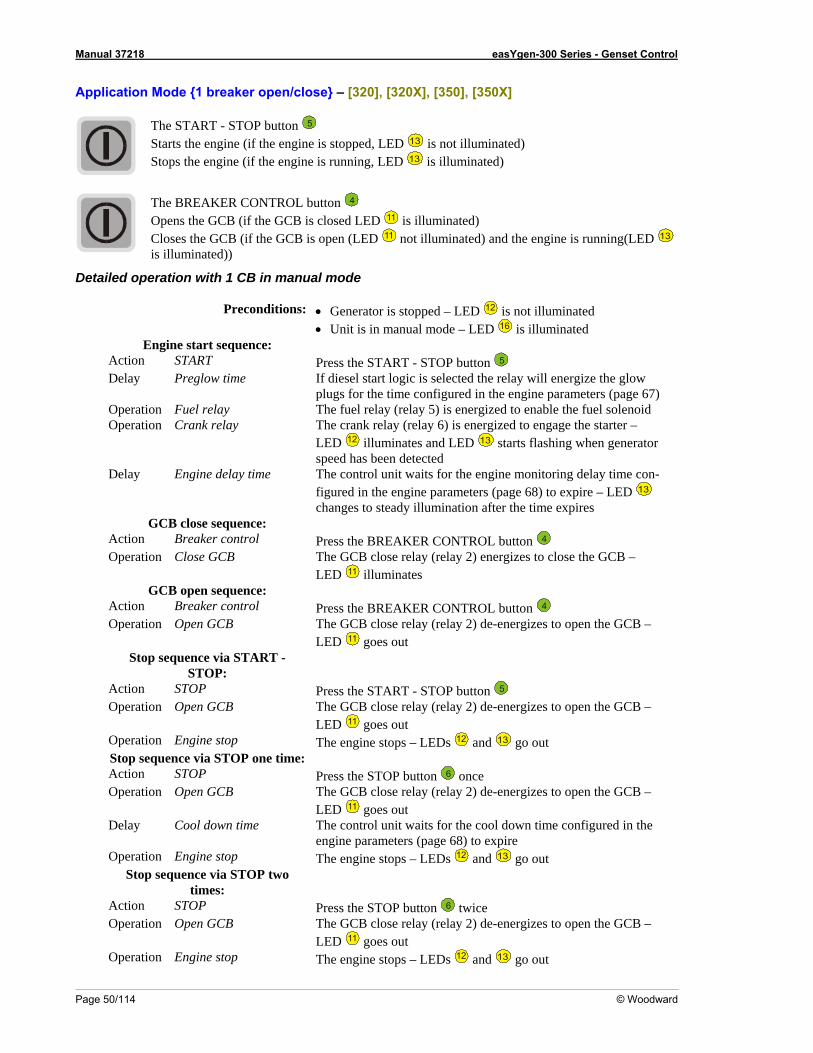
Manual 37218 easYgen-300 Series - Genset Control
Page 50/114 © Woodward
Application Mode 1 breaker open/close – [320], [320X], [350], [350X]
The START - STOP button 5 Starts the engine (if the engine is stopped, LED 13 is not illuminated) Stops the engine (if the engine is running, LED 13 is illuminated)
The BREAKER CONTROL button 4 Opens the GCB (if the GCB is closed LED 11 is illuminated) Closes the GCB (if the GCB is open (LED 11 not illumin ed) and the engine iat s running(LED 13 is illumi
Detailed operation with 1 CB in m
conditio s: • Generator is stopped – LED
nated))
anual mode
Pre n 12 is not illuminated • Unit is in manual mode – LED 16 is illuminated Engine start sequence:
Action START Press the START - STOP button 5 If diesel start logic is selected the relay will energize thDelay Preglow time e gplugs for the time configured in the engine parameters (pag
low e 67)
d Operation Crank relay Operation Fuel relay The fuel relay (relay 5) is energized to enable the fuel solenoi
The crank relay (relay 6) is energized to engage the starter – LED 12 illuminates and LED 13 starts flashing when generator speed has been detected The control unit waits for the engine monitoring delay time cofigured in the engine parameters (pag
Delay Engine delay time n-e 68) to expire – LED 13
changes to steady illumination after the time expires GCB close sequence:
l Action Breaker contro Press the BREAKER CONTROL button 4 The GCB close relay (relay 2) enerOperation Close GCB gizes to close the GCB – LED 11 illuminates GCB open sequence:
ol Action Breaker contr Press the BREAKER CONTROL button 4 The GCB close relay (relay 2) de-energizes to open the GCB – Operation Open GCB LED 11 goes out Stop sequence via START -
STOP: STOP Action Press the START - STOP button 5
Operation Open GCB The GCB close relay (relay 2) de-energizes to open the GCBL D
– E 11 goes out
on Operati Engine stop The engine stops – LEDs 12 and 13 go out me: Stop sequence via STOP one ti
nAction STOP Press the STOP butto 6 once Operation Open GCB The GCB close relay (relay 2) de-energizes to open the GCB –
LED 11 goes out Delay Cool down time The control unit waits for the cool down time configured in the
engine parameters (page 68) to expire Operation Engine stop The engine stops – LEDs 12 and 13 go out
Stop sequence via STOP two times:
Action STOP Press the STOP button 6 twice Operation Open GCB The GCB close relay (relay 2) de-energizes to open the GCB –
LED 11 goes out Operation Engine stop The engine stops – LEDs 12 and 13 go out
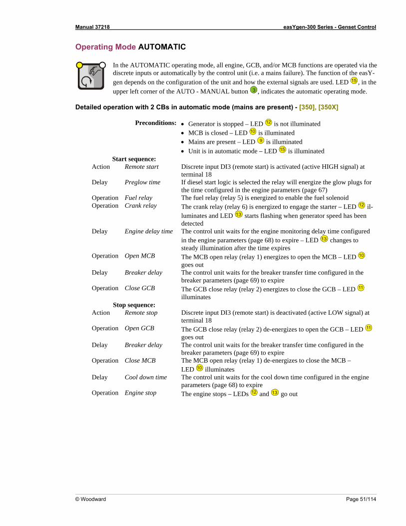
Manual 37218 easYgen-300 Series - Genset Control
© Woodward Page 51/114
Operating Mode AUTOMATIC
In the A e are operated via the discrete inputs or automa i.e e). The function of the easY-gen depends on the confi ed. LED
UTOMATIC op rating mode, all engine, GCB, and/or MCB functionstically by the control unit ( . a mains failurguration of the unit and how the external signals are us
15 , in the
he Aupper left corner of t UTO - MANUAL button 3 , indicate the automatic os perating mode.
Deta rat s in
ons:
iled ope ion with 2 CB automatic mode (mains are present) - [350], [350X]
Preconditi • Generator is stopped – LED 12 is not illuminated • MCB is closed – LED 10 is illuminated • Mains are present – LED 9 is illuminated • Unit is in automat mode – LED ic 15 is illuminated Start sequence:
Delay Preglow time lay will energize the glow plugs for
Operation Fuel relay on
Action Remote start Discrete input DI3 (remote start) is activated (active HIGH signal) at terminal 18 If diesel start logic is selected the rethe time configured in the engine parameters (page 67) The fuel relay (relay 5) is energized to enable the fuel solenoid
Operati Crank relay The crank relay (relay 6) is energized to engage the starter – LED 12 il-luminates and LED 13 starts flashing when generator speed has been
Delay Engine delay time l unit waits for the engine monitoring delay time configured the engine parameters (page 68) to expire – LED
detected The controin 13 changes to
Operation Open MCB en relay (relay 1) energizes to open the MCB – LED steady illumination after the time expires The MCB op 10 goes out The controDelay Breaker delay l unit waits for the breaker transfer time configured in the breaker parameters (page 69) to expire The GCB close relay (relay 2) eOperation Close GCB ergizes to close the GCB – LED n 11 illuminates
Stop sequence: Action Remote stop Discrete input DI3 (remote start) is deactivated (active LOW signal) at
terminal 18 izes to open the GCB – LED Operation Open GCB The GCB close relay (relay 2) de-energ 11
goes out Delay Breaker delay The control unit waits for the breaker transfer time configured in the
breaker parameters (page 69) to expire Operation Close MCB The MCB open relay (relay 1) de-energizes to close the MCB –
LED 10 illuminates Delay Cool down time The control unit waits for the cool down time configured in the engine
parameters (page 68) to expire Operation Engine stop The engine stops – LEDs 12 and 13 go out
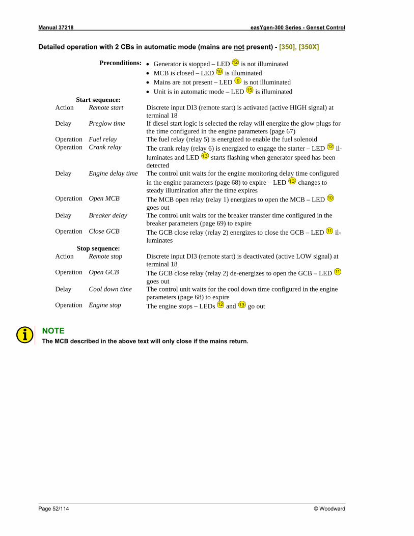
Manual 37218 easYgen-300 Series - Genset Control
Page 52/114 © Woodward
Detailed operation with 2 CBs in automatic mode (mains are not present) - [350], [350X]
Preconditions: • Generator is stopped – LED 12 is not illuminated • MCB is closed – LED 10 is illuminated • Mains are not present – LED 9 is not illuminated • Unit is in automatic mode – LED 15 is illuminated
Start sequence: Action Remote start Discrete input DI3 (remote start) is activated (active HIGH signal) at
terminal 18 Delay Preglow time If diesel start logic is selected the relay will energize the glow plugs for
the time configured in the engine parameters (page 67) Operation Fuel relay The fuel relay (relay 5) is energized to enable the fuel solenoid
p ay zed to engage the starter – LED O eration Crank rel 12 il-The crank relay (relay 6) is energiluminates and LED 13 starts flashing when generator speed has been detected
Delay Engine delay time The control unit waits for the engine monitoring delay time configured in the engine parameters (page 68) to expire – LED 13 changes to steady illumination after the time expires
p The MCB open relay (relay 1) energizes to open the MCB – LED O eration Open MCB 10 goes out
aker delay The control unit waits for the breaker transfer time configured in the rameters (page 69) to expire
p o close the GCB – LED
Delay Brebreaker pa
O eration Close GCB The GCB close relay (relay 2) energizes t 11 il-
c ut DI3 (remote start) is deactivated (active LOW signal) at
p to open the GCB – LED
luminates Stop sequence:
A tion Remote stop Discrete inpterminal 18
O eration Open GCB e relay (relay 2) de-energizesThe GCB clos 11 goes out
D lay Cool down time The control unit waitse for the cool down time configured in the engine parameters (page 68) to expire
ne stop The engine stops – LEDs Operation Engi 12 and 13 go out
NO E
T Th C
e M B described in the above text will only close if the mains return.
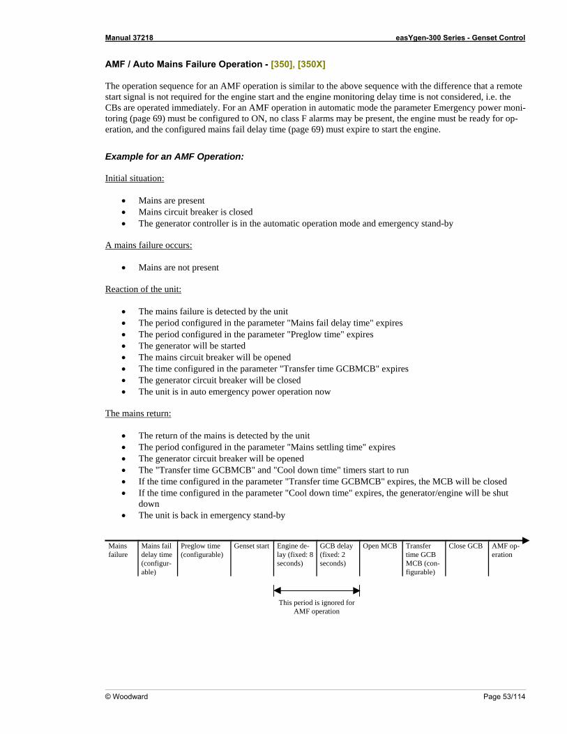
Manual 37218 easYgen-300 Series - Genset Control
© Woodward Page 53/114
AMF / Auto Mains Failure Operation - [350], [350X]
The operation sequenc ence that a remote start signal is not required for the engin idered, i.e. the CBs are oper F operation in automatic mode the parameter Emergency power moni-toring (page 69) m red to -eration, and the configured mains fail d ge 69) must expire to start the engine.
Example for an AM Initial
e for an AMF operation is similar to the above sequence with the differ
e start and the engine monitoring delay time is not consated immediately. For an AM
ust be configu ON, no class F alarms may be present, the engine must be ready for opelay time (pa
F Operation:
situation:
• Mains are present • s ci d• The generator controller is in t y
A ma c
Main rcuit breaker is close he automatic operation mode and emergency stand-b
ins failure o curs:
• Main Reaction of the unit:
s are not present
• The mains failure is detected b• perio e p• The period confi n the p • e tarted • The mains circuit breaker will be opened • The time configured in the parameter "Transfer time GCBMCB" expires • The generator circuit breake• The unit is in auto emerg
he mains return:
y the unit The d configured in th arameter "Mains fail delay time" expires
arameter "Preglow time" expiresgured irator will be sThe gen
r will be closed ency power operation now
T
• The generator circuit breaker will be opened • ime" timers start to run • •
• stand-by Mains failure
configur- seconds) seconds) MCB (con-
• The return of the mains is detected by the unit • The period configured in the parameter "Mains settling time" expires
The "Transfer time GCBMCB" and "Cool down tIf the time configured in the parameter "Transfer time GCBMCB" expires, the MCB will be closed If the time configured in the parameter "Cool down time" expires, the generator/engine will be shut down The unit is back in emergency
Mains fail Preglow time Genset start Engine de- GCB delay Open MCB Transfer Close GCB AMF op-delay time (configurable) lay (fixed: 8 (fixed: 2 time GCB eration (able) figurable)
This period is ignored for
AMF operation
Manual 37218 easYgen-300 Series - Genset Control
Page 54/114 © Woodward
Detailed op
eration with 1 CB in Automatic mode
Preconditions: • Generator is stopped – LED 12 is not illuminated • Unit is in Automatic mode – LED 15 is illuminated
Remote start Discrete input DI3 (remote start) is activated (active HIGH signal) at terminal 18
Delay Preglow time If diesel start logic is selected the relay will energize the glow plugs for the time configured in the engine parameters (page 67)
Operation Fuel relay The fuel relay (relay 5) is energized to enable the fuel solenoid Operation Crank relay The crank relay (relay 6) is energized to engage the starter – LED
Start sequence: Action
12 il-luminates and LED 13 starts flashing when generator speed has been detected
Delay Engine delay time The control unit waits for the engine monitoring delay time configured h rameters (page 68) to expire – LED 13 in t e engine pa changes to
e time expires Operation Close GCB The GCB close relay (relay 2) energizes to close the GCB – LED
steady illumination after th
11 il-luminates
Stop sequence: Action Remote stop Discrete input DI3 (remote start) is deactivated (active LOW signal) at
terminal 18 Operation Open GCB The GCB close relay (relay 2) de-energizes to open the GCB – LED 11
goes out Delay Cool down time The control unit waits for the cool down time configured in the engine
parameters (page 68) to expire Operation Engine stop The engine stops – LEDs 12 and 13 go out
xed breaker closure limits which prevent the GCB closure if the generator voltage hin these limits. These limits depend on the parameters rated system frequency and
If the rated system frequency is set to 50 Hz, the upper limit is at 55 Hz and the lower limit is at 45 Hz. If the rated system frequency is set to 60 Hz, the upper limit is at 66 Hz and the lower limit is at 54 Hz.
Vgenerator must be within Vrated generator +/- 10 % Examples: If the rated generator voltage is set to 400 V, the upper limit is at 440 V and the lower limit is at 360 V. If the rated generator voltage is set to 120 V, the upper limit is at 108 V and the lower limit is at 132 V.
If the generator voltage and/or frequency is/are not within these limits, the generator LED
Breaker Closure Limits ≡≡≡≡≡≡≡≡≡≡≡≡≡≡≡≡≡≡≡≡≡≡
The easYgen-300 series has fiand/or frequency is/are not witrated generator voltage (see Measuring on page 65) and cannot be changed. The limits are set as follows:
fgenerator must be within frated system +/- 10 % Examples:
12 is flashing and the GCB cannot be closed. If the generator voltage and frequency are within these limits, the generator LED 12 is permanently on and the GCB may be closed.
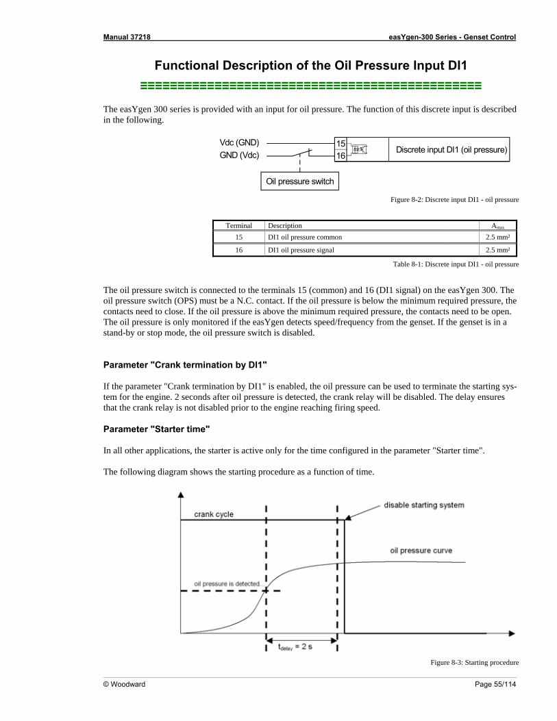
Manual 37218 easYgen-300 Series - Genset Control
© Woodward Page 55/114
Functional Description of the Oil Pressure Input DI1 ≡
≡≡≡≡≡≡≡≡≡≡≡≡≡≡≡≡≡≡≡≡≡≡≡≡≡≡≡≡≡≡≡≡≡≡≡≡≡≡≡≡≡≡≡≡≡ The easYgen 300 series is provided with an input for oil pressure. The function of this discrete input is describedin the following.
Vdc (GND)Discrete input DI1 (oil pressure)GND (Vdc)
Oil pressure switch
1516
Figure 8-2: Discrete input DI1 - oil pressure
Terminal Description Amax
15 DI1 oil pressure common 2.5 mm²
16 DI1 oil pressure signal 2.5 mm²
Table i
he e
he oil pressure is only monitored if the easYgen detects speed/frequency from the genset. If the genset is in a stand-by or stop mode, the oil pressure switch is disabled.
8-1: Discrete input DI1 - o l pressure
The oil pressure switch is connected to the terminals 15 (common) and 16 (DI1 signal) on the easYgen 300. Toil pressure switch (OPS) must be a N.C. contact. If the oil pressure is below the minimum required pressure, thontacts need to close. If the oil pressure is above the minimum required pressure, the contacts need to be open.c
T
Parameter "Crank termination by DI1" If the parameter "Crank termination by DI1" is enabled, the oil pressure can be used to terminate the starting sys-tem for the engine. 2 seconds after oil pressure is detected, the crank relay will be disabled. The delay ensures that the crank relay is not disabled prior to the engine reaching firing speed.
Parameter "Starter time" In all other applications, the starter is active only for the time configured in the parameter "Starter time". The following diagram shows the starting procedure as a function of time.
Figure 8-3: Starting procedure
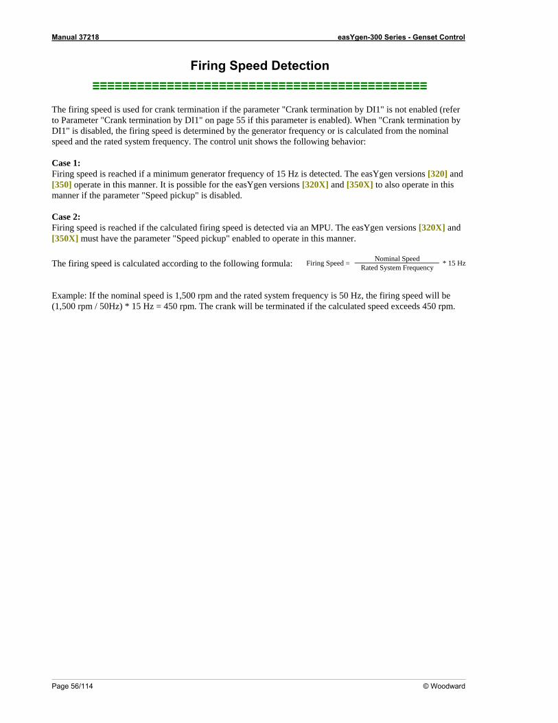
Manual 37218 easYgen-300 Series - Genset Control
Page 56/114 © Woodward
bled (refer Parameter "Crank termination by DI1" on page 55 if this parameter is enabled). When "Crank termination by
d is calculated according to the following formula:
tem frequency is 50 Hz, the firing speed will be minated if the calculated speed exceeds 450 rpm.
Nominal Speed Firing Speed = Rated System Frequency * 15 Hz
Firing Speed Detection ≡≡≡≡≡≡≡≡≡≡≡≡≡≡≡≡≡≡≡≡≡≡≡≡≡≡≡≡≡≡≡≡≡≡≡≡≡≡≡≡≡≡≡≡≡
The firing speed is used for crank termination if the parameter "Crank termination by DI1" is not enatoDI1" is disabled, the firing speed is determined by the generator frequency or is calculated from the nominal speed and the rated system frequency. The control unit shows the following behavior: Case 1: Firing speed is reached if a minimum generator frequency of 15 Hz is detected. The easYgen versions [320] and [350] operate in this manner. It is possible for the easYgen versions [320X] and [350X] to also operate in this manner if the parameter "Speed pickup" is disabled. Case 2: Firing speed is reached if the calculated firing speed is detected via an MPU. The easYgen versions [320X] and [350X] must have the parameter "Speed pickup" enabled to operate in this manner.
he firing speeT Example: If the nominal speed is 1,500 rpm and the rated sys1,500 rpm / 50Hz) * 15 Hz = 450 rpm. The crank will be ter(
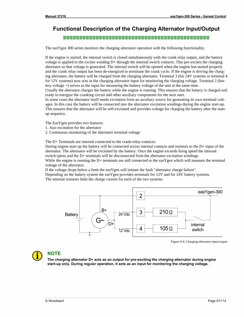
Manual 37218 easYgen-300 Series - Genset Control
© Woodward Page 57/114
Functional Description of the Charging Alternator Input/Output
This pre-excites the charging lternator so that voltage is generated. The internal switch will be opened when the engine has started properly
d
itation from an auxiliary source for generating its own terminal volt-ges. In this case the battery will be connected into the alternator excitation windings during the engine start-up.
ll be self-excitated and provides voltage for charging the battery after the start-p sequence.
he D+ Terminals are internal connected to the crank-relay-contacts: + input of the
lternator. The alternator will be excitated by the battery. Once the engine exceeds firing speed the internal ndings.
the voltage drops below a limit the easYgen will initiate the fault "alternator charge failure". Depending on the battery system the easYgen provides termin r 24V battery systems. The internal resistors limit the harge cur nt fo ach of the tw
≡≡≡≡≡≡≡≡≡≡≡≡≡≡≡≡≡≡≡≡≡≡≡≡≡≡≡≡≡≡≡≡≡≡≡≡≡≡≡≡≡≡≡≡≡ The easYgen 300 series monitors the charging alternator operation with the following functionality. If the engine is started, the internal switch is closed simultaneously with the crank relay output, and the battery voltage is applied to the exciter winding D+ through the internal switch contacts.aand the crank relay output has been de-energized to terminate the crank cycle. If the engine is driving the charg-ing alternator, the battery will be charged from the charging alternator. Terminal 3 (for 24V systems or terminal 4 for 12V systems) now acts as the charging alternator input for monitoring the charging voltage. Terminal 2 (bat-tery voltage +) serves as the input for measuring the battery voltage of the unit at the same time. Usually the alternator charges the battery while the engine is running. This ensures that the battery is charged anready to energize the cranking circuit and other auxiliary components for the next start. In some cases the alternator itself needs excaThis ensures that the alternator wiu The EasYgen provides two features: 1. Aux-excitation for the alternator 2. Continuous monitoring of the alternator terminal voltage TDuring engine-start up the battery will be connected across internal contacts and resistors to the Daswitch opens and the D+ terminals will be disconnected from the alternator excitation wiWhile the engine is running the D+ terminals are still connected to the easYgen which will measure the terminal voltage of the alternator. If
als for 12V and foo systems. c re r e
2
3
4
210 Ω
105 Ωinternalswitch
easYgen-300
B+
D+
Battery 24 Vdc
12 Vdc
G~
Figure 8-4: Charging alternator input/output
NOTE The charging alternator D+ acts as an output for pre-exciting the charging alternator during engine start-up only. During regular operation, it acts as an input for monitoring the charging voltage.
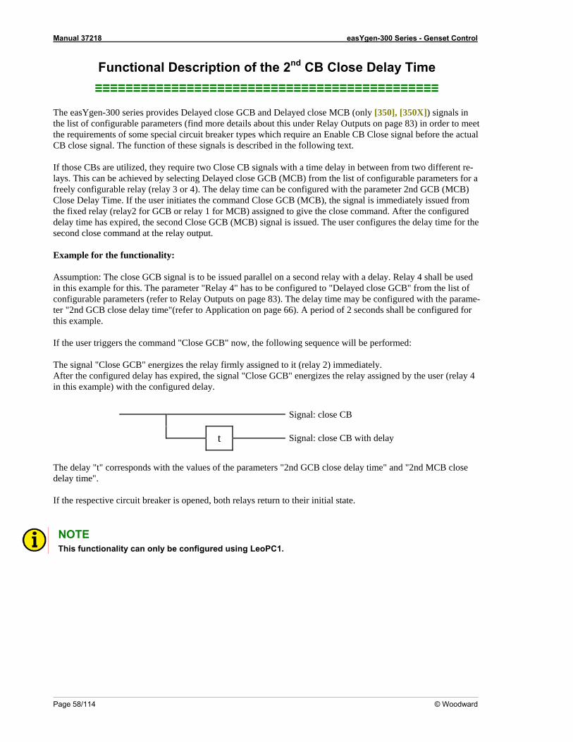
Manual 37218 easYgen-300 Series - Genset Control
Page 58/114 © Woodward
le CB Close signal before the actual B close signal. The function of these signals is described in the following text.
(relay 3 or 4). The delay time can be configured with the parameter 2nd GCB (MCB)
ond close command at the relay output.
Example for the functionality: Assumption: The close GCB signal is to be issued parallel on a second relay with a delay. Relay 4 shall be used in this example for this. The parameter "Relay 4" has to be configured to "Delayed close GCB" from the list of configurable parameters (refer to Relay Outputs on page 83). The delay time may be configured with the parame-ter "2nd GCB close delay time"(refer to Application on page 66). A period of 2 seconds shall be configured for this example. If the user triggers the command "Close GCB" now, the following sequence will be performed: The signal "Close GCB" energizes the relay firmly assigned to it (relay 2) immediately. After the configured delay has expired, the signal "Close GCB" energizes the relay assigned by the user (relay 4 in this example) with the configured delay.
Signal: close CB
Functional Description of the 2nd CB Close Delay Time ≡≡≡≡≡≡≡≡≡≡≡≡≡≡≡≡≡≡≡≡≡≡≡≡≡≡≡≡≡≡≡≡≡≡≡≡≡≡≡≡≡≡≡≡≡
The easYgen-300 series provides Delayed close GCB and Delayed close MCB (only [350], [350X]) signals in the list of configurable parameters (find more details about this under Relay Outputs on page 83) in order to meet the requirements of some special circuit breaker types which require an EnabC If those CBs are utilized, they require two Close CB signals with a time delay in between from two different re-lays. This can be achieved by selecting Delayed close GCB (MCB) from the list of configurable parameters for a freely configurable relayClose Delay Time. If the user initiates the command Close GCB (MCB), the signal is immediately issued fromthe fixed relay (relay2 for GCB or relay 1 for MCB) assigned to give the close command. After the configured delay time has expired, the second Close GCB (MCB) signal is issued. The user configures the delay time for the sec
t Signal: close CB with delay
The delay "t" corresponds with the values of the parameters "2nd GCB close delay time" and "2nd MCB close delay time". If the respective circuit breaker is opened, both relays return to their initial state. NOTE
This functionality can only be configured using LeoPC1.
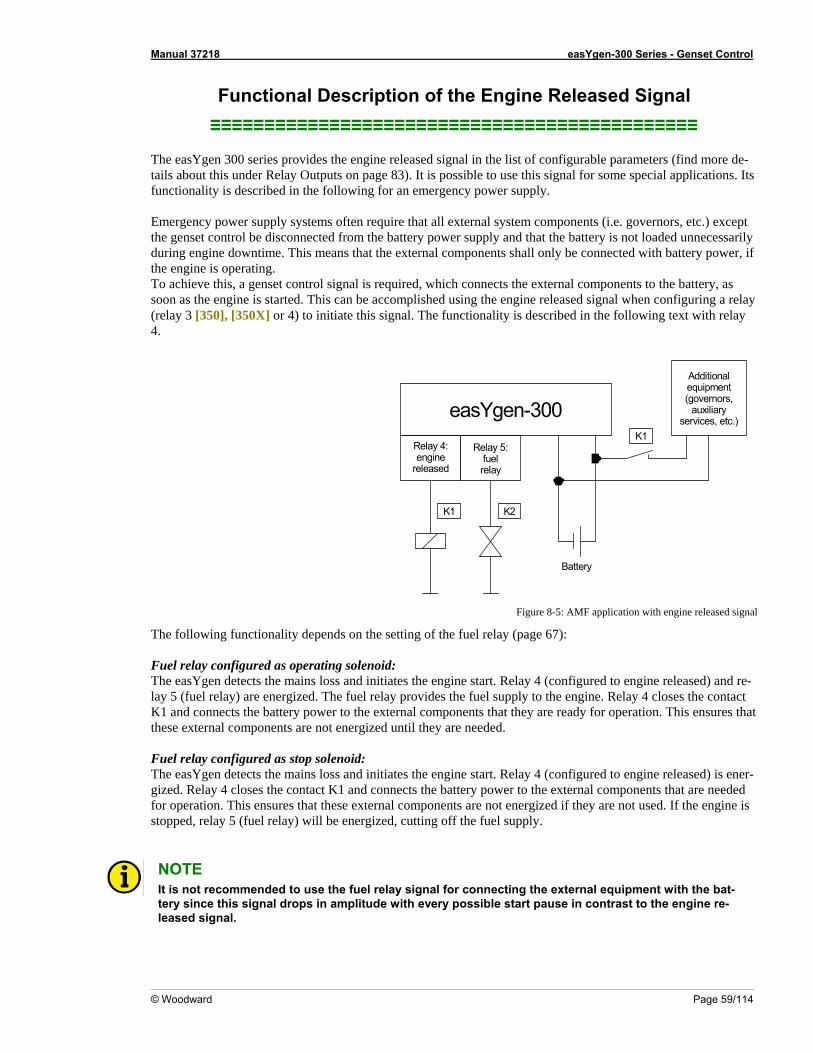
Manual 37218 easYgen-300 Series - Genset Control
© Woodward Page 59/114
Functional Description of the Engine Released Signal ≡≡≡≡≡≡≡≡≡≡≡≡≡≡≡≡≡≡≡≡≡≡≡≡≡≡≡≡≡≡≡≡≡≡≡≡≡≡≡≡≡≡≡≡≡
The easYgen 300 series provides the engine released signal in the list of configurable parameters (find more de-tails about this under Relay Outputs on page 83). It is possible to use this signal for some special applications. Its functionality is described in the foll Emergency power supply syste .e. governors, etc.) except he genset control be disconnec y is not loaded unnecessarily uring engine downtime. This means that the external components shall only be connected with battery power, if
is, a genset control signal is required, which connects the external components to the battery, as engine is started. This can be accomplished using the engine released signal when configuring a relay
( 0], [350X] or 4) to initiate this signal. The functionality is described in the following text with relay 4
owing for an emergency power supply.
ms often require that all external system components (ited from the battery power supply and that the battert
dthe engine is operating. To achieve thsoon as therelay 3 [35.
easYgen-300Relay 4:engine
Relay 5:fuelrelayreleased
K2K1
Additionalequipment(governors,
auxiliaryservices, etc.)
Battery
K1
Figure 8-5: AMF application with engine released signal
e engine start. Relay 4 (configured to engine released) and re- relay provides the fuel supply to the engine. Relay 4 closes the contact
K1 and connects the battery peration. This ensures that these external components ar
uel relay configured as stop
The following functionality depends on the setting of the fuel relay (page 67): Fuel relay configured as operating solenoid:
nd initiates thThe easYgen detects the mains loss alay 5 (fuel relay) are energized. The fuel
power to the external components that they are ready for oe not energized until they are needed.
FT
solenoid: he easYgen detects the mains loss and initiates the engine start. Relay 4 (configured to engine released) is ener-
gized. Relay 4 closes the contact K1 and connects the battery power to the external components that are needed for operation. This ensures that these external components are not energized if they are not used. If the engine is stopped, relay 5 (fuel relay) will be energized, cutting off the fuel supply.
NOTE It is not recommended to use the fuel relay signal for connecting the external equipment with the bat-tery since this signal drops in amplitude with every possible start pause in contrast to the engine re-leased signal.
Manual 37218 easYgen-300 Series - Genset Control
Page 60/114 © Woodward
Chapter 9. Configuration
Restoring Default Values ≡≡≡≡≡≡≡≡≡≡≡≡≡≡≡≡≡≡≡≡≡≡≡≡≡
T a k
he easYgen can be reset to factory settings easily. This may be comfortable for configuring the easYgen fromnown state.
NOTE fault values.
e
Pre•
The unit has to be in Operating Mode STOP (page 46) to load the de
R
conditions for loading the default values: Unit must be in operation mode STOP – LED
setting Via the Front Panel
17 is illuminated • The engine must be stopped – LED 13 is not illuminated • No generator voltage may be present – LED 12 is not illuminated
ss and hold the UP
e 6Pr 7 , ALARM 2 , and STOP buttons simultaneously for at least 10 seconds
Re
•
to reset the values. The factory default values have been restored when all the LEDs flash briefly,.
setting Via LeoPC1
Precondition for loading the default values: Unit has to be in operation mode STOP – LED 17 is illuminated
Setet the parameter Set default values to YES. ow, the default values are loaded.
≡≡≡≡≡≡≡≡≡≡≡≡≡≡≡≡≡≡≡≡≡≡≡≡≡ O he control unit via the front panel is explained in Configuring the easYgen on page 34. Familiarize y y od
Connect the easYgen with your PC and start LeoPC1 as described in Configuration Using the PC on page 61. the parameter Factory settings to YES.
SN
Configuration Via the Front Panel
perating tourself with the unit, the buttons’ meaning/function, and the display monitoring using this section. The displaf the parameters via the front panel and the display of the parameters via the computer program LeoPC1 will iffer.
NOTE Not all parameters may be accessed or changed when configuring the control unit via the front panel.
rly commission a control unit, LeoPC1 v3.1xxx or higher and a DPC cable (P/N 5417-557) are
To properequired.
Manual 37218 easYgen-300 Series - Genset Control
© Woodward Page 61/114
Configuration Using the PC ≡≡≡≡≡≡≡≡≡≡≡≡≡≡≡≡≡≡≡≡≡≡≡≡≡
CAUTION
please use the LeoPC1 software with the following software For the configuration of the unit via the PCversion:
LeoPC1 3.1 or higher NOTE
Please note that configuration using the direct cp
onfiguration cable DPC (product number 5417-557) is ossible starting with revision B of the DPC (first delivered July 2003). If you have an older model
please contact our sales department.
or configuration of the unit via PC program please proceed as follows:
Install the LeoPC1 program on your notebook/PC according to the provided user manual 37146. Consider the
• t the language with which you want to lection of the language re-
oPC1 program works with. This setting
• your notebook/PC. Establish a connection between your notebook/PC and the control unit via the DPC cable. Insert the RJ45
rt on the control unit (see DPC - Direct Configuration Cable on page 31 for details) and the serial cable to the COM1 port of your notebook/PC.
/Woodward/LeoPC1" (version 3.1 or higher) and opening the respective cfg file, or - by a double click on the respective file ending ".cfg" in the subdirectory "/LeoPC1".
e. US for US English or DE for German. After the LeoPC1 program has started, establish communication by pressing the F2 button or selecting Com-
munication -> Connect from the me the control unit and the note-book/PC.
• Start the configuration routi eterize from the menu and adjust the parameter of the
F •
options that are given during the installation. Prior to the completion of the installation you will be prompted to selecstart the PC program. The language of LeoPC1 may be changed at any time. The sefers only to language with which the menus and subprograms that Lewill not change the configured language of the control unit. After the installation of LeoPC1 has been completed it is necessary to reboot
•plug into the RJ45 po
• You can now start the PC program as follows: - by "Start/Program
The cfg files differ in their language used. Use the file on the enclosed floppy disk with the language you want, i.
•nu. This will establish a data link between
ne pressing the F3 button or selecting Devices -> Paramunit to your application using this manual.
NOTE You find detailed information about LeoPC1 and the utilization of the software in the user manual 37146 belonging to it.
NOTE The connection cables delivered with the DPC must be used to connect it to ensure a proper function of the easYgen. An extension or utilization of different cable types for the connection between easYgen and DPC may result in a malfunction of the easYgen. This may further result in damage to components of the system. If an extension of the data connection line is required, only the serial cable between DPC and notebook/PC may be extended.
NOTE Unplug the DPC after configuration to ensure a safe operation! If the DPC remains plugged into the easYgen-300 unit, a safe operation of the unit can not be guaranteed.
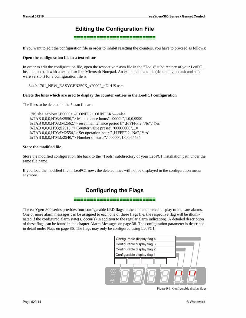
Manual 37218 easYgen-300 Series - Genset Control
Page 62/114 © Woodward
≡≡≡≡≡≡≡≡≡≡≡≡≡≡≡≡≡≡≡≡≡ If you want to edit the configuration file in order to inhibit resetting the counters, you have to proceed as follows
pen the configuration file in a text editor
8440-1701_NEW_EASYGEN350X_x20002_pDirUS.asm Delete the lines which are used to display the counter entries in the LeoPC1 configuration The lines to be deleted in the *.asm file are:
;!K <b> <color=EE0000> --CONFIG.COUNTERS---</b> %TAB 0,0,0,H'03;!z2550,"> Maintenance hours","0000h",1.0,0,9999 %TAB 0,0,0,H'03;!M2562,"> reset maintenance period h" ,H'FFFF,2,"No","Yes" %TAB 0,0,0,H'03;!l2515,"> Counter value preset","00000000",1.0 %TAB 0,0,0,H'03;!M2554,"> Set operation hours" ,H'FFFF,2,"No","Yes" %TAB 0,0,0,H'03;!z2540,"> Number of starts","00000",1.0,0,65535
Store the modified file Store the modified configuration file back to the "Tools" subdirectory of your LeoPsame file name.
If you load the modified file in LeoPC1 now, the deleted lines will not be displayed in the configuration menu anymore.
Configuring the Flags ≡≡≡≡≡≡≡≡≡≡≡≡≡≡≡≡≡≡≡≡≡≡≡≡≡
The easYgen-300 series provides four configurable LED flags in the alphanumerical display to indicate alarms. One or more alarm messages can be assigned to each one of these flags (i.e. the respective flag will be illumi-nated if the configured alarm state(s) occur(s) in addition to the regular alarm indication). A detailed description of these flags can be found in the chapter Alarm Messages on page 38. The configuration parameter is described in detail under Flags on page 86. The flags may only be configured using LeoPC1.
Editing the Configuration File ≡≡≡≡
:
O In order to edit the configuration file, open the respective *.asm file in the "Tools" subdirectory of your LeoPC1installation path with a text editor like Microsoft Notepad. An example of a name (depending on unit and soft-ware version) for a configuration file is:
C1 installation path under the
Configurable display flag 1Configurable display flag 2Configurable display flag 3Configurable display flag 4
Figure 9-1: Configurable display flags
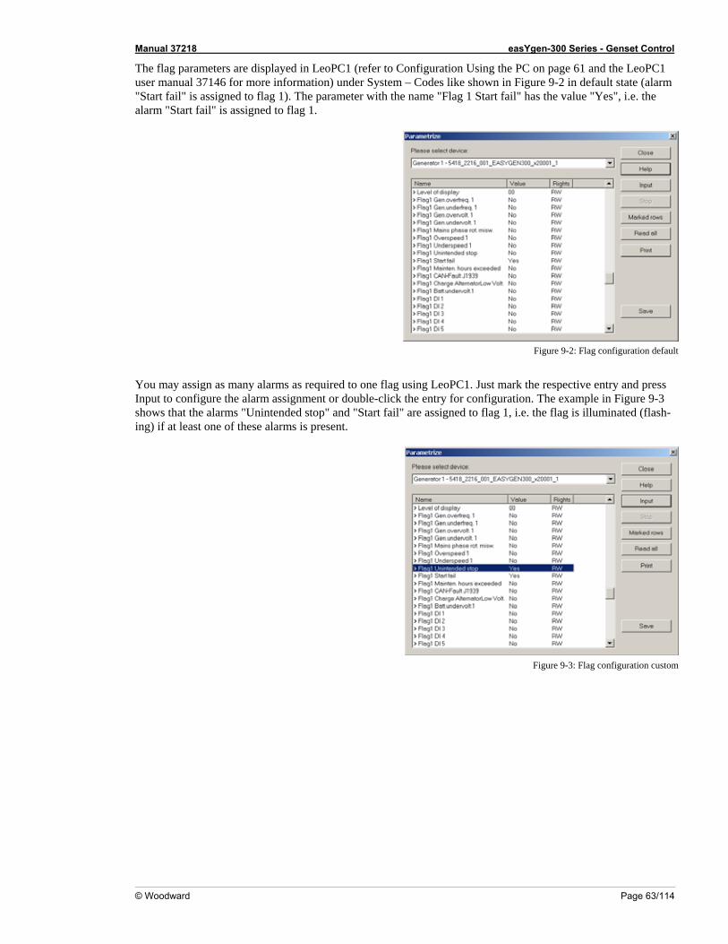
Manual 37218 easYgen-300 Series - Genset Control
© Woodward Page 63/114
The flag parameters are displayed in LeoPC sing the PC on page 61 and the LeoPC1 user manual 37146 for more information) un own in Figure 9-2 in default state (alarm "Start fail" is assigned to flag 1). The param as the value "Yes", i.e. the alarm "Start fail" is assigned to flag 1.
1 (refer to Configuration Uder System – Codes like sh
eter with the name "Flag 1 Start fail" h
Figure 9-2: Flag configuration default
You may assign as many alarms as required to one flag using LeoPC1. Just mark the respective entry and press Input to configure the alarm assignment or double-click the entry for configuration. The example in Figure 9-3 shows that the alarms "Unintended stop" and "Start fail" are assigned to flag 1, i.e. the flag is illuminated (flash-ing) if at least one of these alarms is present.
Figure 9-3: Flag configuration custom
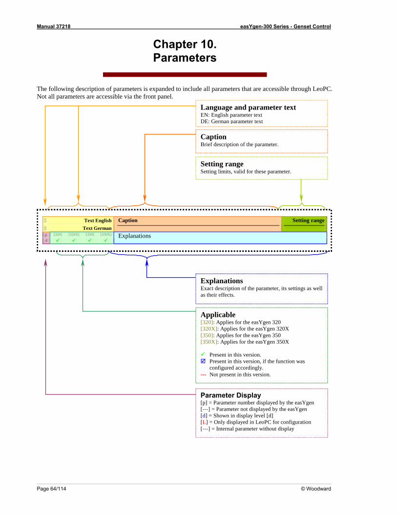
Manual 37218 easYgen-300 Series - Genset Control
Page 64/114 © Woodward
Chapter 10. Parameters
T f sible through LeoPC. i
heNot
fo a a
llowing description o parameters is expanded to include all parameters that are accesll p ra teme rs re a a esscc ble via the front panel.
Language and parameter text EN: English parameter text DE: German parameter text
Applicable [320]: Applies for the easYgen 320
[350X]: Applies for the easYgen 350X
Present in this version. Present in this version, if the function was
configured accordingly. --- Not present in this version.
[320X]: Applies for the easYgen 320X [350]: Applies for the easYgen 350
Explanations ll
Caption Brief description of the parameter.
Exact description of the parameter, its settings as weas their effects.
EN
Text E sh ngli
DE Text German
Caption Setting range
p [320] [320X] [350] [350X]
d Explanations
Setting range rameter. Setting limits, valid for these pa
Parameter Display[p] = Parameter number displayed by the easYgen [---] = Parameter not displayed by the easYgen [d] = Shown in display level [d] [L] = Only displayed in LeoPC for configuration [---] = Internal parameter without display
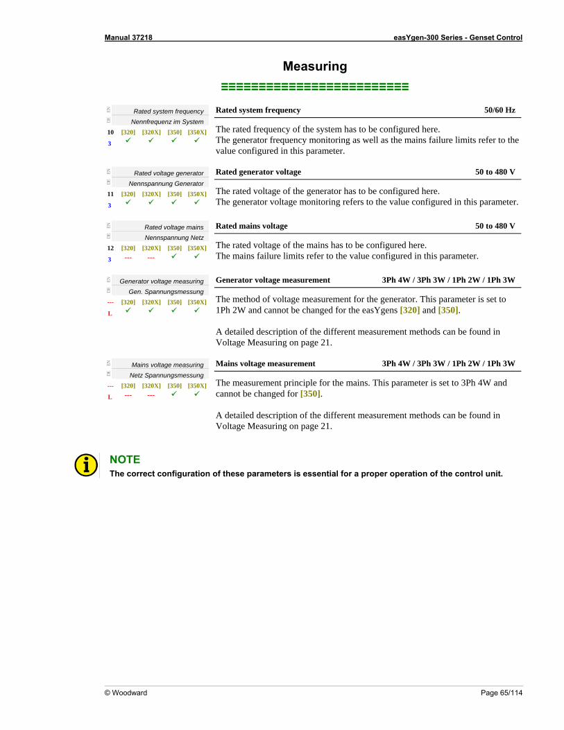
Manual 37218 easYgen-300 Series - Genset Control
© Woodward Page 65/114
EN
Measuring ≡≡≡≡≡≡≡≡≡≡≡≡≡≡≡≡≡≡≡≡≡≡≡≡≡
Rated system frequency DE
Nennfrequenz im System 10 [320] [320X] [350] [350X]
3
Rated system frequency 50/60 Hz
The rated frequency of the system has to be configured here. The generator frequency monitoring as well as the mains failure limits refer to the
EN
value configured in this parameter.
Rated voltage generator
DE
Nennspannung Generator 11 [320] [320X] [350] [350X]
3
Rated generat 50 to 480 V or voltage
The rated voltage of the generator has to be configured here. voltage monitoring refers to the value configured in this parameter.The generator
Rated voltage mains EN
Nennspannung Netz DE
12 [320] [320X] [350] [350X]
Rated mains voltage 50 to 480 V
3 --- --- The rated voltage of the mains has to be configured here.
The mains failure limits refer to the value configured in this parameter.
EN
Generator voltage measuring
DE
Gen. Spannungsmessung --- [320]
L
3Ph 4W / 3Ph 3W / 1Ph 2W / 1Ph 3W
[320X] [350] [350X]
Generator voltage measurement
The method of voltage measurement for the generator. This parameter is set to 1Ph 2W and cannot be changed for the easYgens [320] and [350].
VA detailed description of the different measurement methods can be found in
oltage Measuring on page 21.
EN
Mains voltage measuring
DE
Netz Spannungsmessung [3
Mains voltage measurement 3Ph 4W / 3Ph 3W / 1Ph 2W / 1Ph 3W
--- [320] [320X] [350] 50X]
L --- --- Tc A det measurement methods can be found in Voltage Measuring on page 21.
he measurement principle for the mains. This parameter is set to 3Ph 4W and annot be changed for [350].
ailed description of the different
NOTE The correct configuration of these parameters is essential for a proper operation of the control unit.
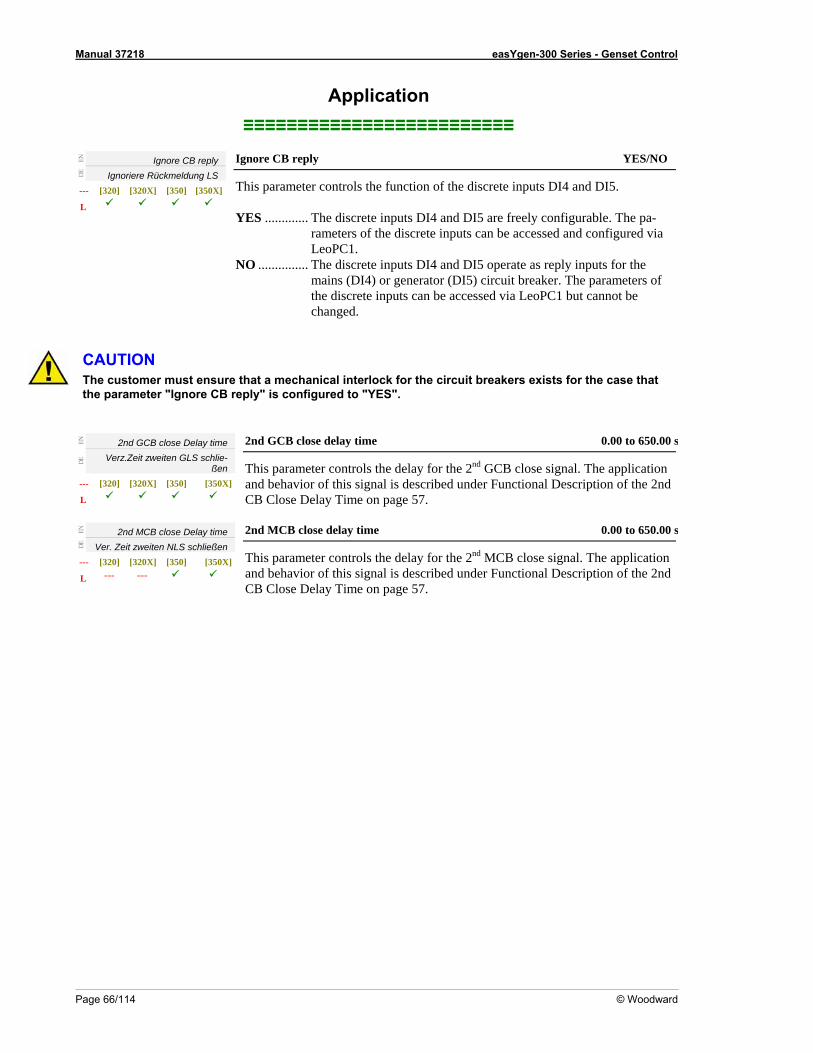
Manual 37218 easYgen-300 Series - Genset Control
Page 66/114 © Woodward
Application
≡≡≡≡≡≡≡≡≡≡≡≡≡≡≡≡≡≡≡≡≡≡≡≡≡
EN
Ignore CB reply
DE
Ignoriere Rückmeldung LS [320] [320X] [350] [350X]
Ignore CB reply YES/NO
---
L
This param s DI4 and DI5.
eter controls the function of the discrete input
YES ............. The discrete inputs DI4 and DI5 are freely configurable. The pa-rameters of the discrete inputs can be accessed and configured via LeoPC1.
be
NO ............... The discrete inputs DI4 and DI5 operate as reply inputs for the mains (DI4) or generator (DI5) circuit breaker. The parameters of the discrete inputs can be accessed via LeoPC1 but cannot changed.
Ahe sto r m t e ure for the case that
the parameter "Ignore CB reply" is configured to "YES".
EN
C UTION T cu me us ns that a mechanical interlock for the circuit breakers exists
2nd GCB close Delay time Verz.Zeit zweiten GLS schlie-DE
ßen --- ]
time 0.00 to 650.00
[320] [320X] [350] [350X
L
2nd GCB close delay s
This parameter controls the delay for the 2 GCB close signal. The applicatand behavior of this signal is described under Functional Description of th
nd ion
EN
e 2nd CB Close Delay Time on page 57.
2nd MCB close Delay time
DE
Ver. Zeit zweiten NLS schließen --- [320] [320X ]
L --- ---
2nd MCB cl 0.00 to 650.00
] [350] [350X
ose delay time s
This paramete l. The application r controls the delay for the 2nd MCB close signaescription of the 2nd
and behavior of this signal is described under Functional DCB Close Delay Time on page 57.
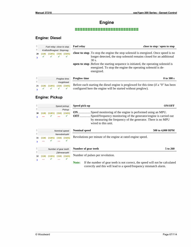
Manual 37218 easYgen-300 Series - Genset Control
© Woodward Page 67/114
Engine ≡≡≡≡≡≡≡≡≡≡≡≡≡≡≡≡≡≡≡≡≡≡≡≡≡
Engine: Diesel
EN
Fuel relay: close to stop
DE
Kraftstoffmagnet: Stopmag. 20 [320] [320X
Fuel relay close to stop / open to stop
] [350] [350X] 3
close to stop .To eed is no stop the engine the stop solenoid is energized. Once sp
Before the starting sequence is initiated, the operating solenoid is zed. To stop the engine the operating solenoid is de-
ergized.
longer detected, the stop solenoid remains closed for an additional30 s.
open to stop .energien
EN
Preglow time
DE
Vorglühzeit 21 [320] [320X] [350] [350X]
3
Preglow time 0 to 300 s
Before each starting the diesel engine is preglowed for this time (if a "0" has been
ngine: Pickup
configured here the engine will be started without preglow).
E
EN
Speed pickup
DE
Pickup 30 [ [320X] [350] [350X]
3 --- --- 320]
Speed pick-up ON/OFF
ON................OFF.............. c ied out
EN
Speed monitoring of the engine is performed using an MPU. Speed/frequency monitoring of the generator/engine is arrby measuring the frequency of the generator. There is no MPUwired to this unit.
Nominal speed
DE
Nenndrehzahl 31 [320] [32
Nominal speed 500 to 4,000 RPM
0X] [350] [350X]
3 --- --- Revolutions per minute of the engine at rated engine speed.
EN
Number of gear teeth
DE
Zähneanzahl 32 [320] [320X] [350] [350X]
3 --- ---
5 to 260 Number of gear teeth
Number of pulses per revolution. Note: If the number of gear teeth is not correct, the speed will not be calculated
correctly and this will lead to a speed/frequency mismatch alarm.
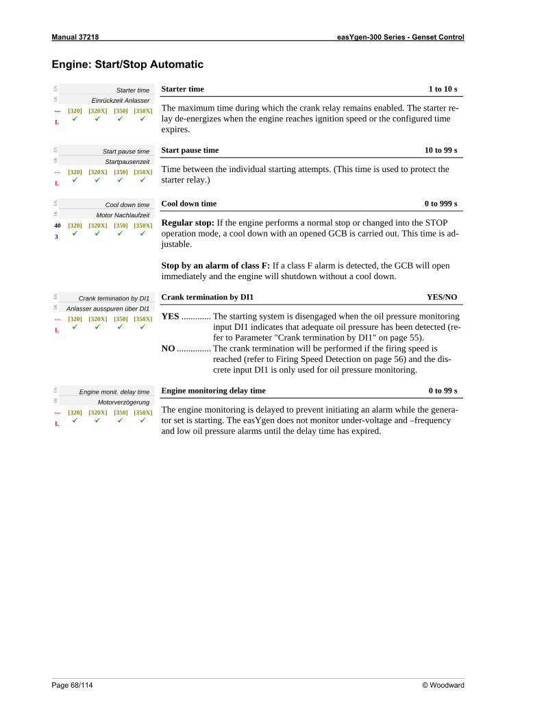
Manual 37218 easYgen-300 Series - Genset Control
Page 68/114 © Woodward
Engine: Start/Stop Automatic
EN
Starter time
DE
Einrückzeit Anlasser --- [320] [320X] [350] [350X]
L
S 1 to 10 s tarter time
The maximum time during which the crank relay remains enabled. The starter re-lay de-energizes when the engine reaches ignition speed or the configured time
EN
expires.
Start pause time
DE
Startpausenzeit --- [320] [320X] [350] [350X]
L
Start pause time 10 to 99 s
Time between the individual starting attempts. (This time is used to protect the starter relay.)
EN
Cool down time
DE
Motor Nachlaufzeit 40 [320] [320X] [350] [350X]
Cool d 0 to 999 s
3
own time
R changed into the STOP o ed out. This time is ad-
immediately a
EN
egular stop: If the engine performs a normal stop orperation mode, a cool down with an opened GCB is carri
justable. Stop by an alarm of class F: If a class F alarm is detected, the GCB will open
nd the engine will shutdown without a cool down.
Crank termination by DI1
DE
Anlasser ausspuren über DI1 --- [320]
YES/NO
[320X] [350] [350X]
L
Crank termination by DI1
YES ............. The starting system is disengaged when the oil pressure monitoring input DI1 indicates that adequate oil pressure has been detected (re-
reached (refer to Firing Speed Detection on page 56) and the dis-
input DI1 is only used for oil pressure monitoring.
EN
fer to Parameter "Crank termination by DI1" on page 55). NO ............... The crank termination will be performed if the firing speed is
crete
Engine monit. delay time
DE
Motor ögerung verz--- [320] [320X] [350] [350X]
L
Engine monitoring delay time 0 to 99 s
The engine monitoring is delayed to prevent initiating an alarm while the generator set is starting. The easYgen does not monitor under-voltage and –frequency and low oil pressure alarms until the delay time has expired.
-
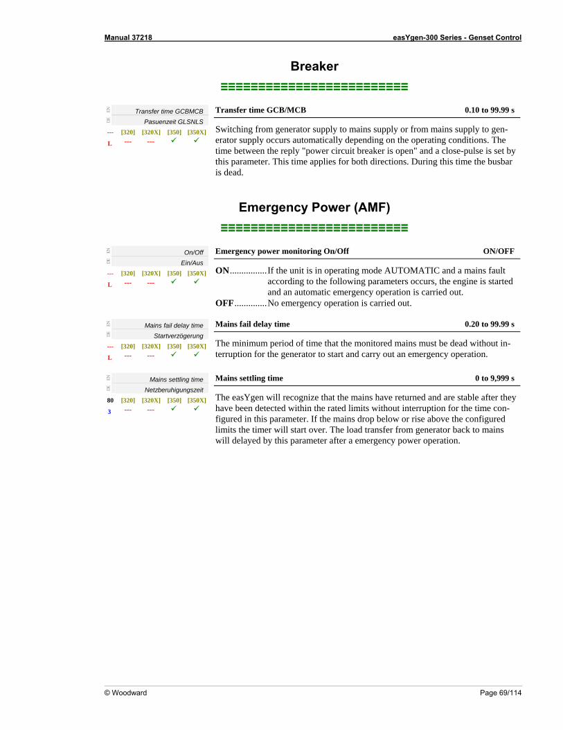
Manual 37218 easYgen-300 Series - Genset Control
© Woodward Page 69/114
Breaker ≡≡≡≡≡≡≡≡≡≡≡≡≡≡≡≡≡≡≡≡≡≡≡≡≡
EN
Transfer time GCBMCB
DE
Pasuenzeit GLSNLS --- [320] [350X] [320X] [350]
L
CB 0.1
--- ---
Transfer time GCB/M 0 to 99.99 s
Switching from generator supply to mains supply or from mains supply to gen-erator supply occurs automatically depending on the operating conditions. The time between the reply "power circuit breaker is open" and a close-pulse is set by this parameter. This time applies for both directions. During this time the busbar is dead.
Emergency Power (AMF) ≡≡≡≡≡≡≡≡≡≡≡≡≡≡≡≡≡≡≡≡≡≡≡≡≡
EN
On/Off
DE
Ein/Aus --- [320] [320X] [350] [350X]
ON/OFF
L --- ---
Emergency power monitoring On/Off
ON................If the unit is in operating mode AUTOMATIC and a mains fault o the following parameters occurs, the engine is started matic emergency operation is carried out.
OFF..............No emergency operation is carried out.
according tand an auto
EN
Mains fail delay time
DE
Startverzögerung --- [320] [320X] [350] [350X]
--- ---
9 s
L
Mains fail delay time 0.20 to 99.9
The minimum period of time that the monitored mains must be dead without in-terruption for the generator to start and carry out an emergency operation.
EN
Mains g settlin time
DE
Netzber nuhigu gszeit 80 [320] [320X] [350] [350X]
3 --- ---
M 0 to 9,999 s ains settling time
The easYgen will recognize that the mains have returned and are stable after they have been detected within the rated limits without interruption for the time con-figured in this parameter. If the mains drop below or rise above the configured limits the timer will start over. The load transfer from generator back to mains
fter a emergency power operation. will delayed by this parameter a
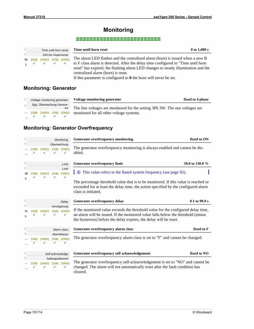
Manual 37218 easYgen-300 Series - Genset Control
Page 70/114 © Woodward
oring ≡≡≡≡≡≡
Monit≡≡≡≡≡≡≡≡≡≡≡≡≡≡≡≡≡≡≡
EN
Time until horn reset
DE
Zeit bis enr Hup eset01 [320] [320X] [350] [350X]
Time until horn reset 0 to 1,000 s
1
The alarm LED flashes and the centralized alarm (horn) is issued when a new B r the delay time configured in "T
LED changes to steady illumcIf this parameter is configured to 0 the horn will never be set.
Monitoring: Generato
to F class alarm is detected. Afte ime until horn reset" has expired, the flashing alarm ination and the entralized alarm (horn) is reset.
r
EN
Voltage monitoring generator
DE Spg. Überwachung Genera-
tor --- [320] [320X] [350] [350X]
---
Voltage monitoring generator fixed to 4 phase
The line voltages are monitored for the setting 3Ph 3W. The star voltages are monitored for all other voltage systems.
Monitoring: toGenera r Overfrequency
EN
Monitoring
DE
Überwachung --- [320] [320X] [350] [350X]
---
Generator overfrequency monitoring fixed to ON
The generator overfrequency monitoring is always enabled and cannot be dis-abled.
EN
Limit
DE
Limit 50 [320] [320X] [350] [350X]
3
Generator overfrequency limit 50.0 to 130.0 %
This value refers to the Rated system frequency (see page 65). The percentage threshold value that is to be monitored. If this value is reached or exceeded for at least the delay time, the action specified by the configured alarm
EN
class is initiated.
Delay
DE
Verzögerung 51 [320] [320X] [350] [350X]
3
0.1 to 99.9 s Generator overfrequency delay
If the monitored value exceeds the threshold value for the configured delay time, an alarm will be issued. If the monitored value falls below the threshold (minus the hysteresis) before the delay expires, the delay will be reset.
EN
Alarm class
DE
Alarmklasse --- [320] [320X] [350] [350X]
---
Generator overfrequency alarm class fixed to F
The generator overfrequency alarm class is set to "F" and cannot be changed.
EN
Self acknowledge
DE
Selbstquittierend --- [320] [320X] [350] [350X]
---
Generator overfrequency self acknowledgement fixed to NO
The generator overfrequency self-acknowledgement is set to "NO" and cannot be changed. The alarm will not automatically reset after the fault condition has cleared.
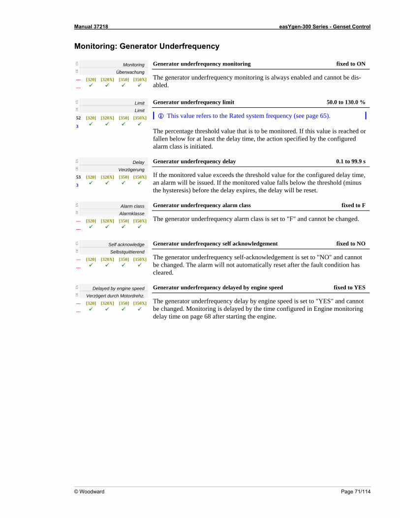
Manual 37218 easYgen-300 Series - Genset Control
© Woodward Page 71/114
cy Monitoring: Generator Underfrequen
EN
Monitoring
DE
Überwachung --- [320] [320X] [350] [350X]
---
Generator underfrequency monitoring fixed to ON
The generator underfrequency monitoring is always enabled and cannot be dis-abled.
EN
Limit
DE
Limit 52
mit
[320] [320X] [350] [350X]
3
Generator underfrequency li 50.0 to 130.0 %
This value refers to the Rated system frequency (see page 65). The percentage threshold value that is to be monitored. If this value is reached or fallen below for at least the delay time, the action specified by the configured alarm class is initiated.
EN
Delay
DE
Verzögerung 53 [320] [320X] [350] [350X]
3
Generator underfrequency de 0.1 to 99.9 s lay
If the monitored value exceeds the threshold value for the configured delay time, an alarm will be issued. If the monitored value falls below the threshold (minus the hysteresis) before the delay expires, the delay will be reset.
EN
Alarm class
DE
Alarmklasse ---
---
[320] [320X] [350] [350X]
Generator underfrequency alarm cl fixed to F ass
The generator underfrequency alarm class is set to "F" and cannot be changed.
EN
Self acknowledge
DE
Selbstquittierend --- [320] [320X] [350] [350X]
---
Generator underfrequency self acknowledgement fixed to NO
The generator underfrequency self-acknowledgement is set to "NO" and cannot be changed. The alarm will not automatically reset after the fault condition hacleared.
s
EN
Delayed by engine speed
DE
Verzögert durch Motordrehz. ---
---
[320] [320X] [350] [350X]
Generator underfrequency delayed by engine sp ixed to YES eed f
The generator underfrequency delay by engine speed is set to "YES" and cannobe changed. Monitoring is delayed by the time configured in Engine monitorindelay time on page 68 afte starting the engine.
t g
r
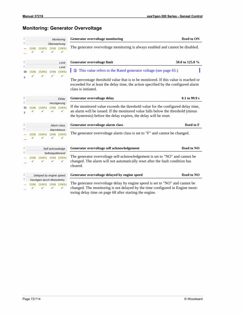
Manual 37218 easYgen-300 Series - Genset Control
Page 72/114 © Woodward
EN
Monitoring: Generator Overvoltage
Monitoring
DE
Überwachung --- [320] [320X] [350] [350X]
---
Generator overvoltage monitoring fixed to ON
The generator overvoltage monitoring is always enabled and cannot be disabled.
EN
Limit
DE
Limit 54 [320] [320X] [350] [350X]
3
Generator overvoltage limit 50.0 to 125.0 %
This value refers to the Rated generator voltage (see page 65.)
m The percentage threshold value that is to be monitored. If this value is reached or exceeded for at least the delay time, the action specified by the configured alarclass is initiated.
EN
Delay
DE
Verzögerung 55 [320] [320X] [350] [350X]
3
Generator overvoltage delay 0.1 to 99.9 s
If the monitored value exceeds the threshold value for the configured delay time, an alarm will be issued. If the monitored value falls below the threshold (minus the hysteresis) before the delay expires, the delay will be reset.
EN
Alarm class
DE
Alarmklasse --- [320] [320X] [350] [350X]
---
Generator overvoltage alarm class fixed to F
The generator overvoltage alarm class is set to "F" and cannot be changed.
EN
Self acknowledge
DE
Selbstquittierend --- [320] [320X] [350] [350X]
---
Generator overvoltage self acknowledgement fixed to NO
The generator overvoltage self-acknowledgement is set to "NO" and cannot be changed. The alarm will not automatically reset after the fault condition has cleared.
EN
Delayed by engine speed
DE
Verzögert durch Motordrehz. --- [320] [320X] [350] [350X]
---
Generator overvoltage delayed by engine speed fixed to NO
The generator overvoltage delay by engine speed is set to "NO" and cannot be changed. The monitoring is not delayed by the time configured in Engine moni-toring delay time on page 68 after starting the engine.
Manual 37218 easYgen-300 Series - Genset Control
© Woodward Page 73/114
tor Undervoltage Monitoring: Genera
EN
Monitoring
DE
Überwachung --- [320] [320X] [350] [350X]
---
Generator undervoltage monitorin fixed to ON g
The generator undervoltage monitoring is always enabled and cannot be disabled.
EN
Limit
DE
Limit 56 [320] [320X] [350] [350X]
3
Generator undervoltage limit to 125.0 % 50.0
This value refers to the Rated generator voltage (see page 65.) The percentage threshold value that is to be monitored. If this value is reached or
alarm class is
fallen below for at least the delay time, the action specified by the configured initiated.
EN
Delay
DE
Verzögerung 57 [320] [320X]
Generator undervoltage delay 0.1 to 99.9 s
[350] [350X]
3 If the monitored value exceeds the threshold value for the configured delay time,
inus the hysteresis) before the delay expires, the delay will be reset. an alarm will be issued. If the monitored value falls below the threshold (m
EN
Alarm class
DE
Alarmklasse --- [320] [320X] [350] [350X]
---
Generator undervoltage alarm class fixed to F
The generator undervoltage alarm class is set to "F" and cannot be changed.
EN
Self acknowledge
DE
Selbstquittierend ---
Generator undervoltage self acknowledgement fixed to NO
[320] [320X] [350] [350X]
--- The generator undervoltage self-acknowledgement is set to "NO" and cannot be changed. The alarm will not automatically reset after the fault condition has cleared.
EN
Delayed by engine speed
DE
Verzögert durch Motordrehz.
--- [320] [320X] [350] [350X]
---
Generator undervoltage delayed by engine speed fixed to YES
The generator undchanged. The mo
ervoltage delay by engine speed is set to "YES" and cannot be nitoring is delayed by the time configured in Engine monitoring
delay time on page 68 after starting the engine.
Manual 37218 easYgen-300 Series - Genset Control
Page 74/114 © Woodward
onitori M ng: Mains
EN
Monitoring
DE
Überwachung --- [320] [320X] [350] [350X]
--- --- ---
ains phase rotation monitoring fixed to ON M
The mains phase rotation monitoring is always enabled and cannot be disabled.
EN
Mains phase rotation
DE
Netzdrehfeld
--- [320] [320X] [350] [350X]
L --- ---
Mains phase rotation direction CW / CCW
CW .............. The three-phase measured mains voltage is rotating CW (clock-wise; that means the voltage rotates in direction A-B-C-Phase; de-fault setting).
CCW ........... The three-phase measured ma CCW (counter clock-wise; that means the vo n C-B-A-
ins voltage is rotatingltage rotates in directio
Phase).
EN
Alarm class
DE
Alarmklasse --- [320] [320X] [350] [350X]
--- --- ---
Mains phase rotation alarm class fixed to B
The mains phase rotation alarm class is set to "B" and cannot be changed.
EN
Self acknowledge
DE
Selbstquittierend --- [ [320X] [350X]
--- --- ---
Mains phase rotation self acknowledgement fixed to NO
320] [350] The mains phase rotation self-acknowledgement is set to "NO" and cannot be changed. The alarm will not automatically reset after the fault condition has cleared.
EN
Delayed by engine speed
DE
Verzögert durch Motordrehz.
--- [320] [3
---
Mains phase rotation delayed by engine speed fixed to NO
20X] [350] [350X]
--- ---
The mains phase rotation delay by engi be ne speed is set to "NO" and cannotc in gine moni-toring delay time on page 68 after starting the engine.
Monitoring: Mains Failure Limits
EN
hanged. The monitoring is not delayed by the time configured En
High voltage threshold
DE
Obere Grenzspannung 81 [320] [320X] [350] [350X]
3 --- ---
Emergency power: high voltage threshold 50.0 to 130.0 %
This value refers to the Rated mains voltage (see page 65). This value is referred to for mains failure recognition and mains estimation. If the monitored value exceeds the adjusted limit, this is recognized as a mains failure and an emergency power operation is initiated.
EN
Low voltage threshold
DE
Untere Grenzspannung 82 [320] [320X] [350] [350X]
3 --- ---
Emergency power: low voltage threshold 50.0 to 130.0 %
This value refers to the Rated mains voltage (see page 65). This value is referred to for mains failure recognition and mains estimation. If the monitored value exceeds the adjusted limit, this is recognized as a mains failure and an emergency power operation is initiated.
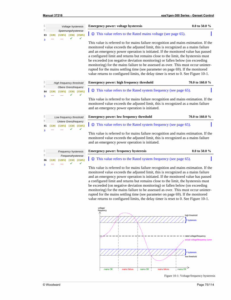
Manual 37218 easYgen-300 Series - Genset Control
© Woodward Page 75/114
EN
Voltage hysteresis
DE
Spannungshysterese 83 [320] [320X] [350] [350X]
--- ---
er: voltage hysteresis 0.0 to 50.0 % Emergency pow
This value refers to the Rated mains voltage (see page 65). This value is referred to for mains failure recognition and mains estimation. If the monitored value exceeds the adjusted limit, this is recognized as a mains failure
3
and an emergency power operation is initiatea configured limit and returns but remains cl
d. If the monitored value has passed ose to the limit, the hysteresis must
ve deviation monitoring) or fallen below (oins failure to be assessed as over. This must
be exceeded (on negati n exceeding monitoring) for the ma occur uninter-rupted for the mains settling time (see parameter on page 69). If the monitored value returns to configured limits, the delay timer is reset to 0. See Figure 10-1.
EN
High frequency threshold
DE
Obere Grenzfrequenz 84 [320] [320X] [350] [350X]
power: high frequency threshold 70.0 to 160.0 % Emergency
This value refers to the Rated system frequency (see page 65). This value is referred to for mains failure recognition and mains estimation. If the monitored value exceeds the adjusted limit, this is recognized as a mains failure and an emergency power operation is initiated.
--- --- 3
EN
Low frequency threshold
DE
Untere Grenzfrequenz 85 [320] [320X] [350] [350X]
--- 3 ---
Emergency power: low frequen o 160.0 % cy threshold 70.0 t
This value refers to the Rated system frequency (see page 65). This value is referred to for mains failure recognition and mains estimation. If the
mit, this is recognized as a maitiated.
monitored value exceeds the adjusted li ins failure and an emergency power operation is in
EN
Frequency hysteresis Frequenzhysterese
[320] [320X] [350] [350X] ---
0 %
---
Emergency power: frequency hysteresis 0.0 to 50.
Thi
DE
86
3
s value refers to the Rated system frequency (see page 65). This value is referred to for mains failure recognition and mains estimation. If the
ilure ed
rn
monitoring) for the mains failure to be assessed as over. This must occur uninter-rupted for the mains settling time (see parameter on page 69). If the monitored value returns to configured limits, the delay timer is reset to 0. See Figure 10-1.
monitored value exceeds the adjusted limit, this is recognized as a mains faand an emergency power operation is initiated. If the monitored value has passa configured limit and retu s but remains close to the limit, the hysteresis must be exceeded (on negative deviation monitoring) or fallen below (on exceeding
high threshold
low threshold
rated voltage/frequency
actual voltage/frequency curve
hysteresis
hysteresis
mains failure mains failuremains OK mains OK mains OK
voltage/frequency
Figure 10-1: Voltage/frequency hysteresis
Manual 37218 easYgen-300 Series - Genset Control
Page 76/114 © Woodward
Monitoring: Engine Overspeed
EN
Monitoring
DE
Überwachung 58 [320] [320X] [350] [350X]
3 --- ---
Engine overspeed monitoring ON / OFF
ON ............... Overspeed monitoring of the engine speed is carried out according to the following parameters.
OFF ............. No monitoring is carried out.
EN
Limit
DE
Limit 59 [ [320X] [350X]
--- ---
Engine overspeed limit 0 to 9,999 RPM
320] [350]
3
The threshold value is set by this parameter. If this value is reached or exceeded for at least the delay time, the action specified by the configured alarm class is initiated.
EN
Delay
DE
Verzögerung --- [ [320X] [350X]
--- --- --- 320] [350]
Engine overspeed delay fixed to 0.1 s
If the monitored value exceeds the threshold value for the configured delay time, the threshold (minus
the hysteresis) before the delay expires, the delay will be reset. This value is fixed to 0.1 seconds and cannot be changed.
an alarm will be issued. If the monitored value falls below
EN
Alarm class
DE
Alarmklasse --- [320] [320X] [350] [350X]
--- --- ---
Engine overspeed alarm class fixed to F
The engine overspeed alarm class is set to "F" and cannot be changed.
EN
Self acknowledge
DE
Selbstquittierend --- [320] [320X] [350] [350X]
--- ---
NO
---
Engine overspeed self acknowledgement fixed to
The engine overspeed selchanged. The alarm
f-acknowledgement is set to "NO" and cannot be will not automatically reset after the fault condition has
cleared.
EN
Delayed by engine speed
DE
Verzöge rch rdrrt du Moto ehz. --- [320] [320X] [350] [350X]
--- --- ---
NO Engine overspeed delayed by engine speed fixed to
The engine overspeed delay by engine speed is set to "NO" and cannot be changed. The moni ng is not delayed by the ttori ime configured in Engine moni-toring delay time on page 68 after starting the engine.
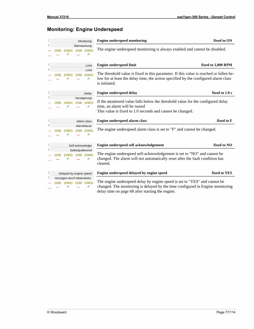
Manual 37218 easYgen-300 Series - Genset Control
© Woodward Page 77/114
d Monitoring: Engine Underspee
EN
Monitoring
DE
Überwachung --- [320] [320X] [350] [350X]
--- --- ---
Engine underspeed monitoring fixed to ON
The engine underspeed monitoring is always enabled and cannot be disabled.
EN
Limit
DE
Limit --- [320] [320X] [350] [350X]
--- --- ---
Engine underspeed limit ,000 RPM fixed to 1
The threshold value is fixed in this parameter. If this value is reached or fallen be-low for at least the delay time, the action specified by the configured alarm clis initiated.
ass
EN
Delay
DE
Verzögerung --- [320] [320X] [350] [350X]
Engine underspeed delay fixed to 1.0 s
--- --- --- If the monitored value falls below the threshold value for the configured delay
This value is fixed to 1.0 seconds and cannot be changed.
EN
time, an alarm will be issued
Alarm class
DE
Alarmklasse --- [320] [320X] [350] [350X]
--- --- ---
Engine underspeed alarm class fixed to F
The engine underspeed alarm class is set to "F" and cannot be changed.
EN
Self acknowledge
DE
Selbstquittierend --- [320] [320X] [350] [350X]
--- --- ---
Engine underspeed self acknowledgement fixed to NO
The engine underspeedchanged. The alarm wil
self-acknowledgement is set to "NO" and cannot be l not automatically reset after the fault condition has
EN
cleared.
Delayed by engine speed
DE
Verzögert durch Motordrehz. --- [3 [320X] [350] [350X]
--- --- 20]
---
Engine underspeed delayed by engine speed fixed to YES
The engine underspeed delay by engine speed is set to "YES" and cannot be changed. The monitoring is delayed by the time configured in Engine monitoring
the engine.
delay time on page 68 after starting
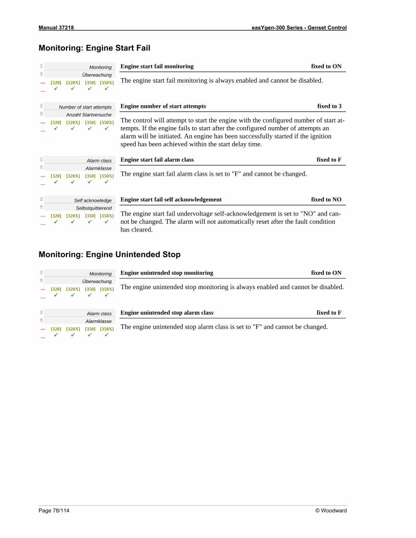
Manual 37218 easYgen-300 Series - Genset Control
Page 78/114 © Woodward
Monitoring: Engine Start Fail
EN
Monitoring
DE
Überwachung --- [320] [320X] [350] [350X]
---
Engine start fail monitoring fixed to ON
The engine start fail monitoring is always enabled and cannot be disabled.
EN
Number of start attempts
DE
Anzahl Startversuche ---
---
Engine number of start attempts fixed to 3
[320] [320X] [350] [350X]
The control will attempt to start the engine with the configured number of start attempts. If the engine fails to start after the configured number of attempts an alarm will be
-
initiated. An engine has been successfully started if the ignition speed has been achieved within the start delay time.
EN
Alarm class
DE
Alarmklasse --- [320] [320X] [350X]
---
Engine start fail alarm class fixed to F
[350] The engine start fail alarm class is set to "F" and cannot be changed.
EN
Self acknowledge
DE
Selbstquittierend --- [320] [320X] [350] [350X]
---
Engine start fail self acknowledgem xed to NO ent fi
The engine start fail undervoltage self-acknowledgement is set to "NO" and can-not be changed. The alarm will not automatically reset after the fault condition has cleared.
: U
Monitoring ine Eng nintended Stop
EN
Monitoring
DE
Überwachung --- [320] [320X] [350] [350X]
---
Engine unintended stop monitoring fixed to ON
The engine unintended stop monitoring is alway sabled.s enabled and cannot be di
EN
Alarm class
DE
Alarmklasse --- [320] [320X] [350] [350X]
---
m fixed to F Engine unintended stop alar class
The engine unintended stop alarm class is set to "F" and cannot be changed.
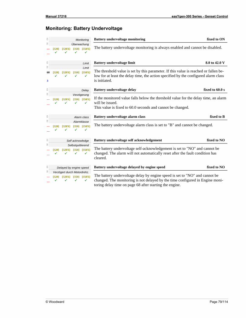
Manual 37218 easYgen-300 Series - Genset Control
© Woodward Page 79/114
Monitoring: Battery Undervoltage
EN
Monitoring
DE
Überwachung --- [320] [320X] [350] [350X]
---
Battery undervoltage monitoring ixed to ON f
The battery undervoltage monitoring is always enabled and cannot be disabled.
EN
Limit
DE
Limit 60 [320] [320X] [350]
3
Battery undervoltage limit 8.0 to 42.0 V
[350X]
The threshold value is set by this parameter. If this value is reached or fallen be-low for at least the delay time, the action specified by the configured alarm class is initiated.
EN
Delay
DE
Verzögerung --- [320] [320X] [350] [350X]
Battery undervoltage delay fixed to 60.0 s
--- If the monitored value falls below the threshold value for the delay time, an alarm will be issued. This value is fixed to 60.0 seconds and cannot be changed.
EN
Alarm class
DE
Alarmklasse --- [320] [320X]
Battery undervoltage alarm class fixed to B
[350] [350X]
--- The battery undervoltage alarm class is set to "B" and cannot be changed.
EN
Self acknowledge
DE
Selbstquittierend --- [320] [320
Battery undervoltage self acknowledgement fixed to NO
X] [350] [350X]
--- The battery undervoltage self-acknowledgement is set to "NO" and cannot be changed. The alarm will not automatically reset after the fault condition has cleared.
EN
Delayed by engine speed
DE
Verzögert durch Motordrehz. --- [320] [320X] [350] [350X]
Battery undervoltage delayed by engine speed fixed to NO
--- The battery undervoltage delay by engine speed is set to "NO" and cannot be
changed. The monitoring is not delayed by the time configured in Engine moni-toring delay time on page 68 after starting the engine.
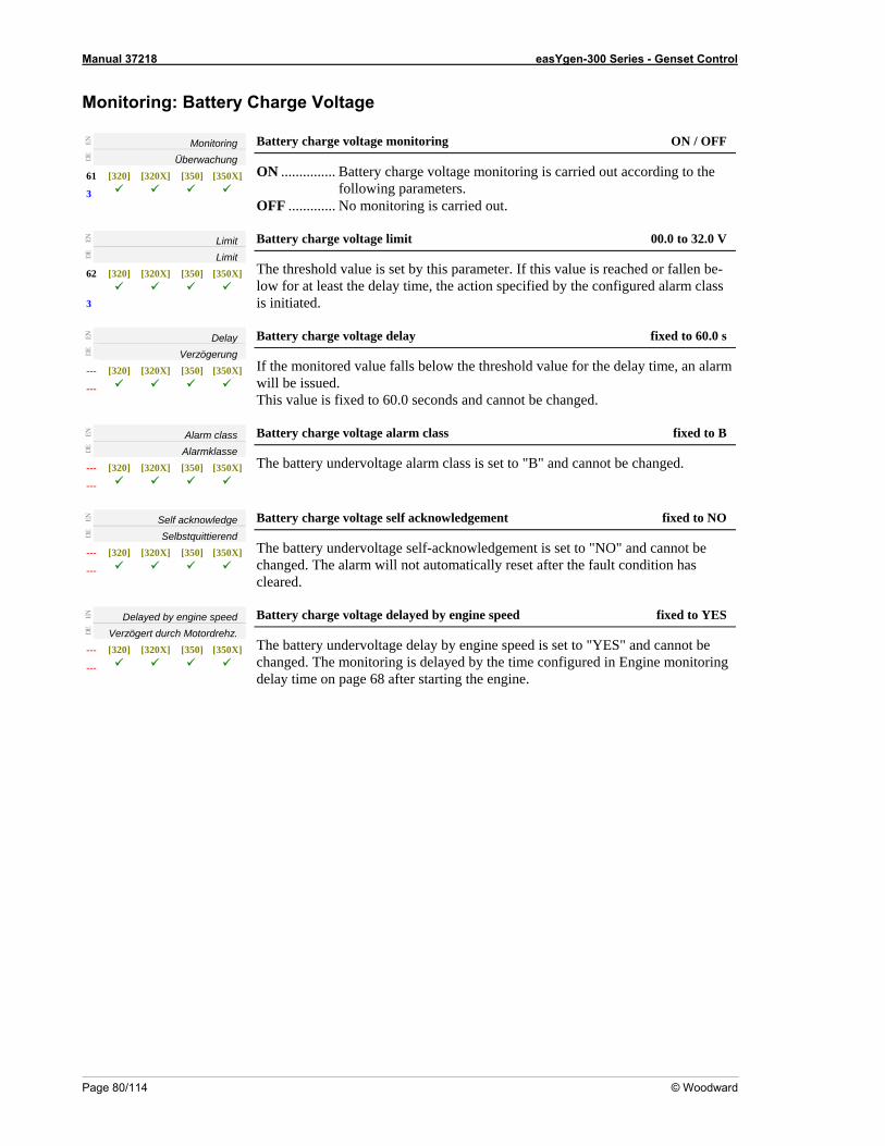
Manual 37218 easYgen-300 Series - Genset Control
Page 80/114 © Woodward
arge Voltage Monitoring: Battery Ch
EN
Monitoring
DE
Überwachung 61
3
toring
[320] [320X] [350] [350X]
Battery charge voltage moni ON / OFF
ON ............... Battery charge voltage monitoring is carried out according to the following parameters.
OFF ............. No monitoring is carried out.
EN
Limit
DE
Limit 62 [320] [320X] [350] [350X]
3
Battery charge voltage limit 00.0 to 32.0 V
The threshold value is set by this parameter. If this value is reached or fallen be-low for at least the delay time, the action specified by the configured alarm class is initiated.
EN
Delay
DE
Verzögerung --- [ [320X] [350X]
---
fixed to 60.0 s
320] [350]
Battery charge voltage delay
If the monitored value falls below the threshold value for the delay time, an alarmwill be issued. This value is fixed to 60.0 seconds and cannot be changed.
EN
Alarm class
DE
Alarmklasse --- [320] [320
fixed to B
X] [350] [350X]
---
Battery charge voltage alarm class
The battery undervoltage alarm class is set to "B" and cannot . be changed
EN
Self acknowledge
DE
Selbstquittierend --- [320] [320X] [350] [350X]
---
Battery charge voltage self acknowledgement fixed to NO
The battery uchanged. The alarm
ndervoltage self-acknowledgement is set to "NO" and cannot be will not automatically reset after the fault condition has
cleared.
EN
Delayed by engine speed
DE
Verzöge rch rdrrt du Moto ehz. --- [320] [320X] [350] [350X]
---
Battery charge voltage delayed by engine speed fixed to YES
The battery uonitoring
ndervoltage delay by engine speed is set to "YES" and cannot be changed. The monitoring is delayed by the time configured in Engine mdelay time on page 68 after starting the engine.
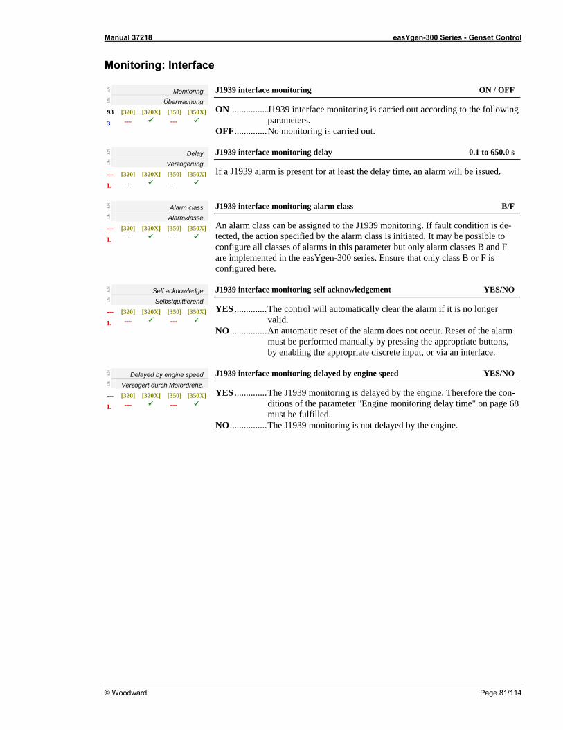
Manual 37218 easYgen-300 Series - Genset Control
© Woodward Page 81/114
Monitoring: Interface
EN
Monitoring
DE
Überwachung 93 [320] [320X] [350] [350X]
3 --- ---
J ON / OFF 1939 interface monitoring
ON................J1939 interface monitoring is carried out according to the following parameters.
OFF..............No monitoring is carried out.
EN
Delay
DE
Verzögerung --- [320] [320X] [350] [350X]
--- L ---
J1939 interface monitoring delay 0.1 to 650.0 s
If a J1939 alarm is present for at least the delay time, an alarm will be issued.
EN
Alarm class
DE
Alarmklasse --- [320] [320X] [350] [350X]
L --- ---
F J1939 interface monitoring alarm class B/
An alarm class can be assigned to the J1939 monitoring. If fault condition is de-
configure all only alarm classes B and F
configured he
tected, the action specified by the alarm class is initiated. It may be possible to classes of alarms in this parameter but
are implemented in the easYgen-300 series. Ensure that only class B or F is re.
EN
Self acknowledge
DE
Selbstquittierend --- [320] [320X] [350] [350X]
L --- ---
J1939 interface monitoring s YES/NO elf acknowledgement
YES ..............The control will automatically clear the alarm if it is no longer valid.
NO................An automatic reset of the alarm does not occur. Reset of the alarm must be performed manually by pressing the appropriate buttons,
ropriate discrete inpby enabling the app ut, or via an interface.
EN
Delayed by engine speed
DE
V öge rch ordrerz rt du Mot ehz. --- [320] [320X] [350] [350X]
L --- ---
J peed YES/NO 1939 interface monitoring delayed by engine s
YES ..............The J1939 monitoring is delayed by the engine. Therefore the coditions of the parameter "Engine monitoring delay time" on page 6must be fulfilled.
n-8
O................The J1939 monitoring is not delayed by the engine.
N
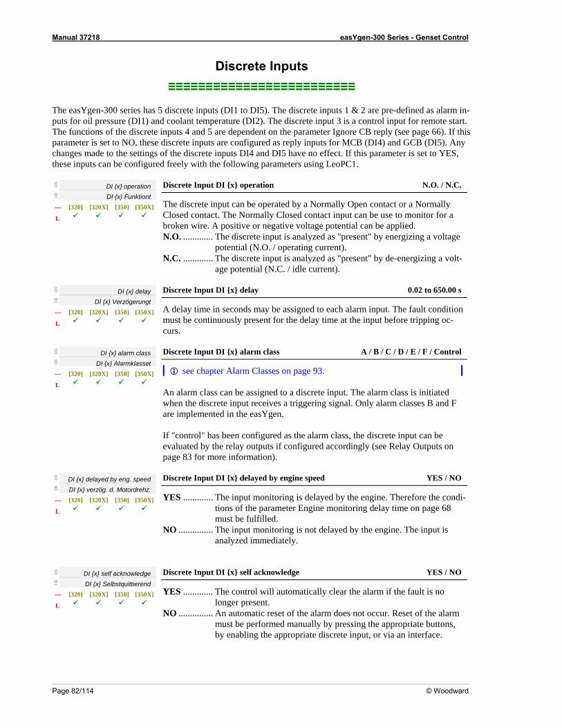
Manual 37218 easYgen-300 Series - Genset Control
Page 82/114 © Woodward
n- is a contr
dent on the parameter Ignore CB reply (see page 66). If this arameter is set to NO, these discrete inputs are configured as reply inputs for MCB (DI4) and GCB (DI5). Any anges made to the o I5 have no effect. If this param
nputs can be ed
Discrete Inputs ≡≡≡≡≡≡≡≡≡≡≡≡≡≡≡≡≡≡≡≡≡≡≡≡≡
The easYgen-300 series has 5 discrete inputs (DI1 to DI5). The discrete inputs 1 & 2 are pre-defined as alarm iputs for oil pressure (DI1) and coolant temperature (DI2). The discrete input 3 ol input for remote start. The functions of the discrete inputs 4 and 5 are depenpch settings f the discrete inputs DI4 and D eter is set to YES, these i configur freely with the following parameters using LeoPC1.
EN
DI x operation
DE
DI x Funktiont --- [320] [320X] [350]
Discrete Input DI x operation N.O. / N.C.
[350X]
L The discrete inp or a Normally Closed contact o monitor for a
ut can be operated by a Normally Open contact. The Normally Closed contact input can be use t
N.O. ............. The discrete input is analyzed as "present" by energizing a voltage potential (N.O. / operating current).
ut is analyzed age potential (N.C. / idle current).
N
broken wire. A positive or negative voltage potential can be applied.
N.C. ............. The discrete inp as "present" by de-energizing a volt-
E DI x d elay
DE
DI x Verzögerungt --- [320] [320X] [350] [350X]
0.02 to 650.00 s
L
Discrete Input DI x delay
A delay time in ach alarm input. The fault condition must be continu e at the input before tripping oc-
seconds may be assigned to eously present for the delay tim
curs.
EN
DI x alarm class
DE
DI x Alarmklasset --- [320] [320X] [350]
A / B / C / D / E / F / Control
[350X]
L
Discrete Input DI x alarm class
see chapter Alarm Classes on page 93. An alarm class can be assigned to a discrete input. The alarm class is initiated when the discrete input receives a triggering signal. Only alarm classes B and F are implemented in the easYgen.
nput can be lay Outputs on
page 83 for more information).
If "control" has been configured as the alarm class, the discrete ievaluated by the relay outputs if configured accordingly (see Re
EN
DI x delayed by eng. speed
DE
DI x verzög. d. Motordrehz. --- [320] [320X] [350] [350X]
L
Discrete Input DI x delayed by engine speed YES / NO
YES ............. The input monitoring is delayed by the engine. Therefore the condi-rameter Engine mon age 68
must be fulfilled. N ..... The input monitoring is not delaye he input is
analyzed immediately.
tions of the pa itoring delay time on p
O .......... d by the engine. T
EN
DI x self acknowledge
DE
DI x Selbstquittierend --- [320] [320X] [350]
[350X]
Discrete Input DI x self acknowledge YES / NO
L Y control will automatically cle
longer present. NO ............... An automatic reset of the alarm does not occur. Reset of the alarm
must be performed ma byby enabling the appropriate discrete input, or via an interface.
ES ............. The ar the alarm if the fault is no
nually pressing the appropriate buttons,
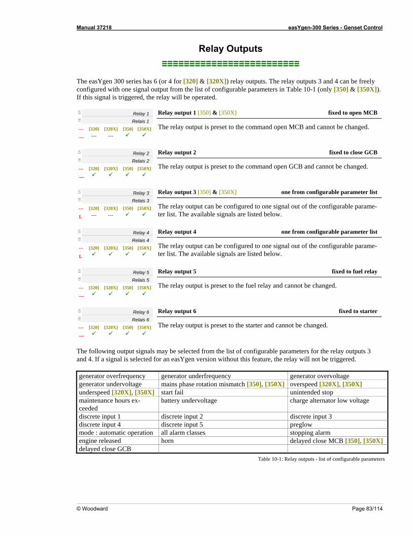
Manual 37218 easYgen-300 Series - Genset Control
© Woodward Page 83/114
Re ts
e easYge 6 (or 4 for [320] & [320X]) relay outputs. The relay outputs 3 and 4 can be freely nfig utput from [350] & [350X]).
r
EN
lay Outpu≡≡≡≡≡≡≡≡≡≡≡≡≡≡≡≡≡≡≡≡≡≡≡≡≡
Th n 300 series hasco ured with one signal o the list of configurable parameters in Table 10-1 (only
lay will be operated. If this signal is triggered, the e
Relay 1
DE
Relais 1 --- [320] [320X] [350] [350X]
--- --- ---
B Relay output 1 [350] & [350X] fixed to open MC
The relay output is preset to the command open MCB and cannot be changed.
EN
Relay 2
DE
Relais 2 --- [320] [320X] [350] [350X]
fixed to close GCB
---
Relay output 2
The relay output is preset to the command open GCB and cannot be changed.
EN
Relay 3
DE
Relais 3 --- [320]
L --- [320X] [350] [350X]
---
Relay output 3 [350] & [350X] one from configurable parameter list
The relay output can be confi e parame-ter list. The available
gured to one signal out of the configurabl signals are listed below.
EN
Relay 4
DE
Relais 4 --- [320] [320X
Relay output 4 one from configurable parameter list
] [350] [350X] L
The relay output can be configured to one signal out of the configurable parame-ter list. The available signals are listed below.
EN
Relay 5
DE
Relais 5 --- [320] [320X] [350] [350X]
ay
---
Relay output 5 fixed to fuel rel
The relay output is preset to the fuel relay and cannot be changed.
EN
Relay 6
DE
Relais 6 --- [320] [320X] [350] [350X]
---
Relay output 6 fixed to starter
The relay output is preset to the starter and cannot be changed.
The following output signals may be selected from the list of configurable parameters for the relay outputs 3 and 4. If a signal is selected for an easYgen version without this feature, the relay will not be triggered. generator overfrequency generator underfrequency generator overvoltage generator undervoltage mains phase rotation mismatch [350], [350X] overspeed [320X], [350X] underspeed [320X], [350X] start fail unintended stop maintenance hours ex-ceeded
battery undervoltage charge alternator low voltage
discrete input 1 discrete input 2 discrete input 3 discrete input 4 discrete input 5 preglow mode : automatic operation all alarm classes stopping alarm engine released horn delayed close MCB [350], [350X] delayed close GCB
Table 10-1: Relay outputs - list of configurable parameters
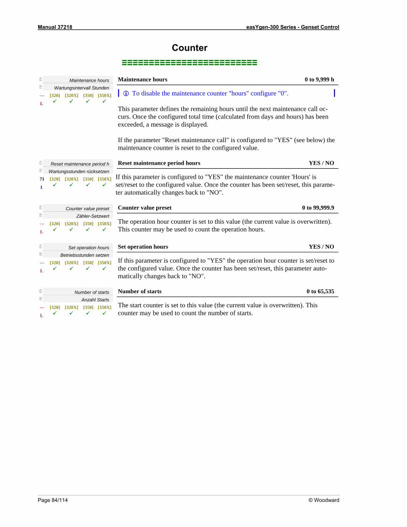
Manual 37218 easYgen-300 Series - Genset Control
Page 84/114 © Woodward
Counter ≡≡≡≡≡≡≡≡≡≡≡≡≡≡≡≡≡≡≡≡≡≡≡≡≡
EN
Maintenance hours
DE
Wartungsintervall Stunden --- [320] [320X] [350]
Maintenance hours 0 to 9,999 h
[350X] L
To disabl gure "0". e the maintenance counter "hours" confi This parameter defines the remaining hours curs. Once the configured total time (calcula
until the next maintenance call oc-ted from days and hours) has been
exceeded, a message is displayed. If the parameter "Reset maintenance call" is configured to "YES" (see below) the maintenance counter is reset to the configured value.
EN
Reset maintenance period h
DE
Wartungsstunden rücksetzen 71 [320]
1 [320X] [350] [350X]
Reset maintenance period hours YES / NO
If this parameter is configured to "YES" the maintenance counter 'Hours' is set/reset to the configured value. Once the counter has been set/reset, this parame-ter automatically changes back to "NO".
EN
Counter value preset
DE
Zähler-Setzwert --- [ [320X] [350X]
L
Counter value preset 0 to 99,999.9
320 [35] 0] The operation hour counter is set to this value (the current value is overwrittemay be use
n). This counter d to count the operation hours.
EN
Set operation hours
DE
Betriebsstunden setzen --- [320] [320X] [350] [350X]
L
Set operation hours YES / NO
If this parameter is configured to "YES" the operation hour counter is set/resed value. Once the counter has been set/reset, this parameter auto-nges back to "NO".
t to the configurematically cha
EN
Number of starts
DE
Anzahl Starts --- [320] [320X] [350] [350X]
L
Number of starts 0 to 65,535
The start counter is set to this value (the current value is overwritten). This counter may be used to count the number of starts.
Manual 37218 easYgen-300 Series - Genset Control
© Woodward Page 85/114
Interfaces ≡≡≡≡≡≡≡≡≡≡≡≡≡≡≡≡≡≡≡≡≡≡≡≡≡
CAN Interface
Baudrate EN
DE
Baudrate --- [320] [320X] [350] [350X]
L --- ---
CAN baudrate 20/50/100/125/250/500/800/1000 kBd
The CAN bus baudrate is configured here.
NOTEThe bau
d rate is the same for all devices connected to the CAN bus regardless of the selected protocol.
J1939
Device type EN
DE
Betriebsmodus 90 [320] [32
J1939 device type Off/Standard/S6 Scania/EMR
0X] [350] [350X] 3 --- ---
Off ................The yed. J1939 visualization is disabled. No values are displa
LeoPC1. S6 Scania .....The standard J1939 messages are displayed on the unit and in
LeoPC1, and the Scania S6 messages are displayed in LeoPC1 in addition. The Scania S6 messages do not appear on the unit.
EMR ............The standard J1939 messages are displayed on the unit and in LeoPC1, and the Deutz EMR2 messages are displayed in LeoPC1 in addition. The Deutz EMR2 messages do not appear on the unit.
EN
Standard......The standard J1939 messages are displayed on the unit and in
Request send address
DE
Request Sendeadresse 91 [320] [320X] [350] [350X]
3 --- ---
J1939 request send address 0 to 255
The J1939 protocol device number: This is necessary for requesting special pa-rameter groups. The acknowledgement command for passive alarms will also be sent with this participant address (Diagnostic Data Clear/Reset of Previously Active DTCs - DM3).
EN
Receive device number
DE
Empf. Geräte Nummer 92 [320] [320X] [350] [350X]
3 --- ---
J1939 receive device number 0 to 255
Indicates the number of the J1939 device, whose data shall be visualized.
You find detailed information about the J1939 protocol under J1939 Protocol Descriptions starting on page 95.
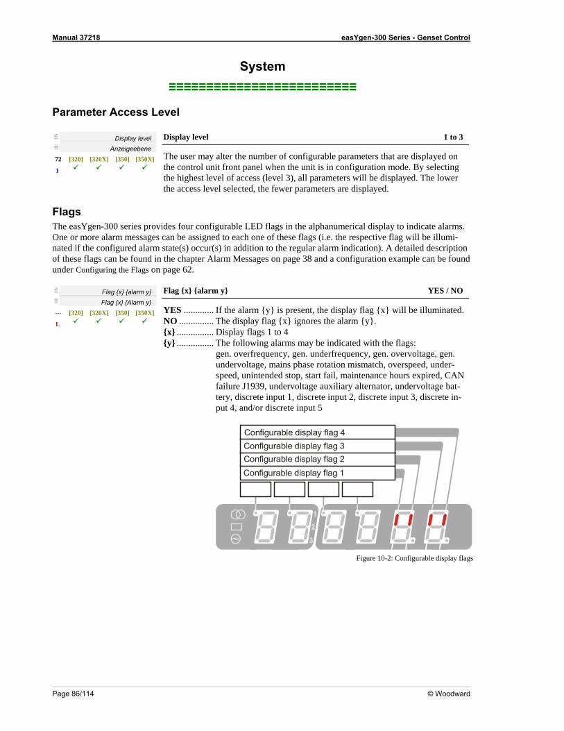
Manual 37218 easYgen-300 Series - Genset Control
Page 86/114 © Woodward
System ≡≡≡≡≡≡≡≡≡≡≡≡≡≡≡≡≡≡≡≡≡≡≡≡≡
P
arameter Access Level
Display level EN
Anzeigeebene DE
72 [320] [320X] [350] [350X]
Display level 1 to 3
1
The user may alter the number of configurable parameters that are displayed on the control unit front panel when the unit is in configuration mode. By selecting the highest level of access (level 3), all parameters will be displayed. The lower the access level selected, the fewer parameters are displayed.
ags e easYg v alarms.
r s lumi-ed i he configured al m state(s) occur(s) in addition to the regular alarm indication). A detailed description
f these flags can be found in t essages on page 38 and a configuration example can be found der Configurin n
FlTh en-300 series pro ides four configurable LED flags in the alphanumerical display to indicate
can be assigned to each one of these flags (i.e. the respective flag will be ilOne or more ala m messageno
at f t arhe chapter Alarm M
page 62. un g the Flags o
EN
Flag x alarm y
DE
Flag larm x A y[320] [320X] [350] [350X]
YES / NO Flag x alarm y
YES ............. If the alarm y is present, the display flag x will be illuminated. . The display flag x ignores the alarm y.
gen. overfrequency, gen. underfrequency, gen. overvoltage, gen. undervoltage, mains phase rotation mismatch, overspeed, under-
intended stop, start fail, maintenance hours ex
discrete in-put 4, and/or discrete input 5
--- NO ..............x ................ Display flags 1 to 4 y ................ The following alarms may be indicated with the flags:
L
speed, un pired, CAN failure J1939, undervoltage auxiliary alternator, undervoltage bat-tery, discrete input 1, discrete input 2, discrete input 3,
Configurable display flag 1Configurable display flag 2Configurable display flag 3Configurable display flag 4
Figure 10-2: Configurable display flags
Manual 37218 easYgen-300 Series - Genset Control
© Woodward Page 87/114
Versions NOTE The following parameters are not configurable. They may be viewed using LeoPC1 for information pur- poses only.
EN
Serial number
DE
Seriennummer --- [320] [320X [350] [350X] ]
Serial number (S/N) display only
This is the serial number of the easYgen and identifies the control clearly. L
EN Boot item number
DE
Boot Artikelnummer --- [320] [320X] [350] [350X]
Boot item number (P/N) display only
L
This is the item number of the firmware, which is stored on the easYgen.
EN
Boot revision
DE
Boot Revision --- [320] [320X] [350] [350X]
L
Boot rev display only ision (REV)
T the easYgen. his is the revision of the firmware, which is stored on
EN
Boot version Boot version display only
DE
Boot Version --- [320] [320X] [350] [350X]
This is the version (Vx.xxxx) of the firmware, which is stored on the easYgen.
L
EN
Program item number
DE
Programm Artikelnummer --- [320] [320X] [350] [350X]
Program item number display only
This is the item number of the application software of the easYgen. L
EN
Program revision
DE
Programm Revision
Program revision display only
This is the revision of the application software of the easYgen. --- [320] [320X] [350] [350X]
L
EN
Program version
DE
Programm Version --- [320] [320X] [350] [350X]
L
y Program version display onl
This is the version (Vx.xxxx) of the application software of the easYgen.
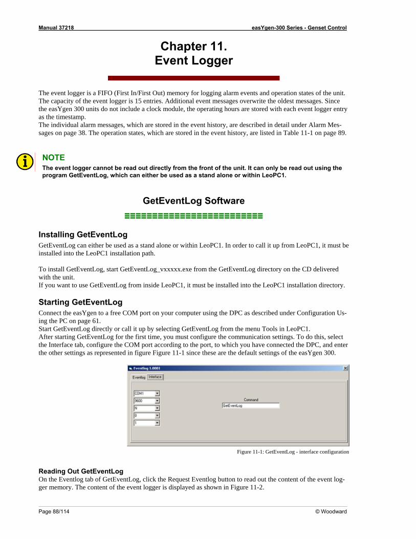
Manual 37218 easYgen-300 Series - Genset Control
Page 88/114 © Woodward
Chapter 11. Event Logger
The event logger is a FIFO (First In/First Out) memory for logging alarm events and operation states of the unit. The capacity of the event logger is 15 entries. Additional event messages overwrite the oldest messages. Since the easYgen 300 units do not include a clock module, the operating hours are stored with each event logger entry as the timestamp.
he individual alarm messages, which are stored in the event history, are described in detail under Alarm Mes-n 9.
Tsages on page 38. The operation states, which are stored in the event history, are listed in Table 11-1 o page 8 NOTE The event logger cannot be read out directly from the front of the unit. It can only be read out using the program GetEventLog, which can either be used as a stand alone or within LeoPC1.
G Log Software≡≡≡≡≡≡≡≡≡≡≡≡≡≡≡≡≡≡≡≡≡≡≡≡≡
Installing GetEventLog GetEventLog can either be used as a sta r within LeoPC1. In ord o call it m L C1, it m e installed into the LeoPC1 installatio pa
o install GetEventLog, start GetEventLog_vxxxxx.exe from the GetEventLog directory on the CD delivered with the unit.
from inside LeoPC1, it must be installed into the LeoPC1 installation directory.
Starting GetEventLog t on your computer using the DPC as described under Configuration Us-
eoPC1. After starting GetEventLog for the first time, you must configure the communication settings. To do this, select
ter gure 11-1 since these are the default settings of the easYgen 300.
etEvent
nd alone oth.
er t up fro eoP ust bn
T
If you want to use GetEventLog
Connect the easYgen to a free COM poring the PC on page 61. Start GetEventLog directly or call it up by selecting GetEventLog from the menu Tools in L
the Interface tab, configure the COM port according to the port, to which you have connected the DPC, and enthe other settings as represented in figure Fi
Figure 11-1: GetEventLog - interface configuration
Reading Out GetEventLog On the Eventlog tab of GetEventLog, click the Request Eventlog button to read out the content of the event log-ger memory. The content of the event logger is displayed as shown in Figure 11-2.
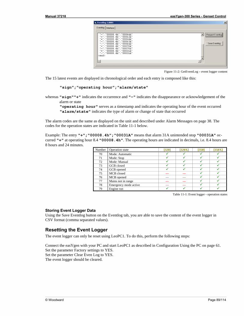
Manual 37218 easYgen-300 Series - Genset Control
© Woodward Page 89/114
Figure 11-2: GetEventLog – event logger content
The 15 latest events are displayed in chronological order and each entry is comp
"sign";"operating hour";"alarm/stat whereas "sign""+" indicates the occurrence and "-" indi the
alarm or state "operating hour" serves as a timestamp and i ti vent occurred "alarm/state" indicates the type of alarm or change of state that occurred
Example: The entry "+";"00008.4h";"00031A" mcurred "+" at operating hour 8.4 "00008.4h". The operat8 hours and 24 minut
Number Operation state
osed like this:
e"
cates the disappearance or acknowledgement of
ndicates the opera ng hour of the e
The alarm codes are the same as displayed on the unit and described under Alarm Messages on page 38. Thecodes for the operation in Table 11-1 states are indicated below.
eans that alarm 31A unintended stop "00031A" oc-ing hours are indicated in decimals, i.e. 8.4 hours are
es. [320] [320X] [350] [350X]
70 Mode: Automatic 71 Mode: Stop 72 Mode: Manual 73 GCB closed 74 GCB opened 75 MCB closed --- --- 76 MCB opened --- --- 77 Mains not in range --- --- 78 Emerge tive --- --- ncy mode ac79 Engine run
Table 11-1: Event logger - operation states
Storing Event LogUsing the Save Event
Resetting the EvThe event logger can only be reset using LeoPC1. To do Connect the easYgen with your PC and start LeoPC1 as described in Configuration Using thSet the parameter Fact . Set the parameter CleaThe event logger should be cl
ger Data log button on the Eventlog tab, you are able to save the content of the event logger in
CSV format (comma separated values).
ent Logger this, perform the following steps:
e PC on page 61. ory settings to YESr Even Log to YES.
eared.
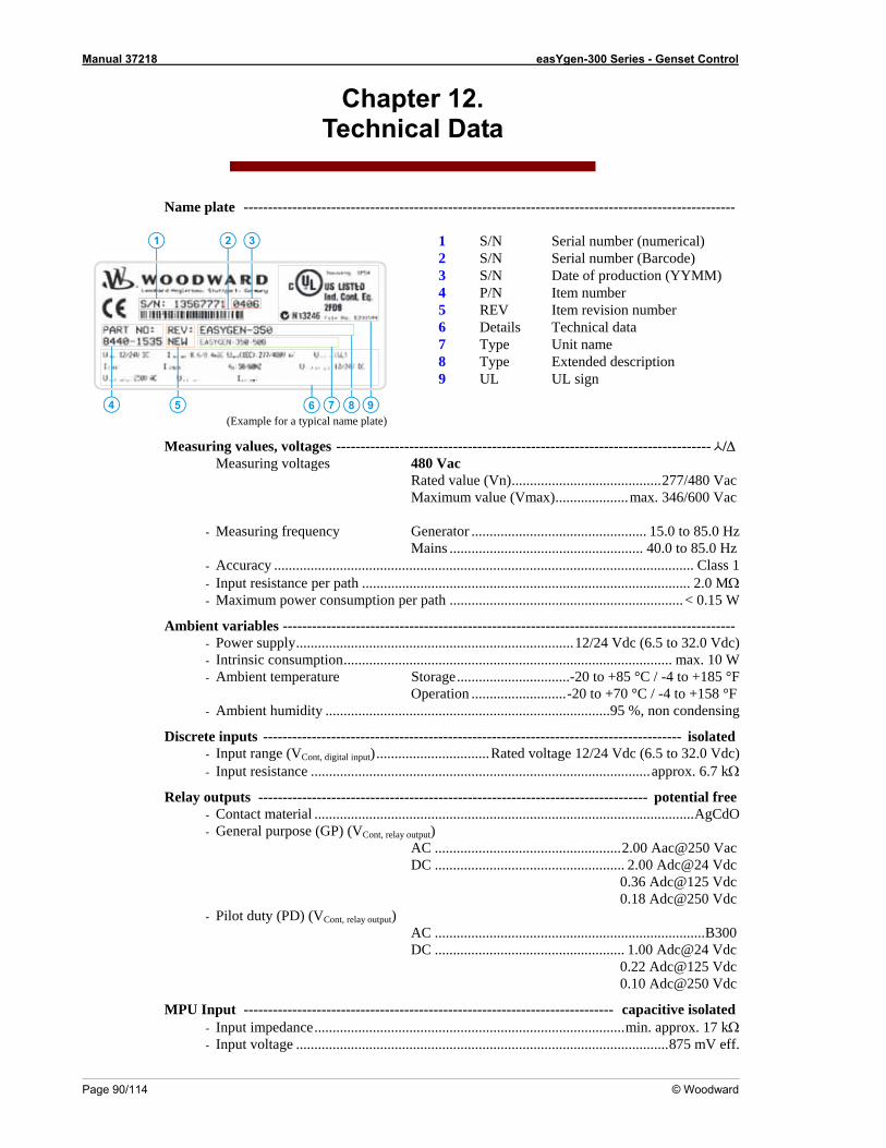
Manual 37218 easYgen-300 Series - Genset Control
Page 90/114 © Woodward
Chapter 12. Technical Data
Name plate -----------------------------------------------------------------------------------------------------
1 S/N Serial number (numerical) 2 S/N Serial number (Barcode)
1 2 3
4 5 9876
3 S/N Date of production (YYMM) 4 P/N Item number
(Example for a typical name plate)
6 Details Technical data 5 REV Item revision number
7 Type Unit name 8 Type Extended description 9 UL UL sign
Measuring values, voltages ----------------------------------------------------------------------------- /∆ Measuring voltages 480 Vac Rated value (Vn).........................................277/480 Vac
..................................................... 40.0 to 85.0 Hz - - put resistance per path .............- aximum power consumption per path ............................
Ambie
- Ambient temperature Storage...............................-20 to +85 °C / -4 to +185 °F Operation ..........................-20 to +70 °C / -4 to +158 °F
Discre
- Input resistance .............................................................................................approx. 6.7 kΩ
Relay
- General purpose (GP) (VCont, relay output) AC ...................................................2.00 Aac@250 Vac
0.36 Adc@125 Vdc
0.10 Adc@250 Vdc
MPU - Input impedance.....................................................................................min. approx. 17 kΩ - Input voltage ......................................................................................................875 mV eff.
Maximum value (Vmax)....................max. 346/600 Vac
- Measuring frequency Generator ................................................ 15.0 to 85.0 Hz Mains
Accuracy ................................................................................................................... Class 1 In ............................................................................. 2.0 MΩ M ....................................< 0.15 W
nt variables --------------------------------------------------------------------------------------------- - Power supply............................................................................12/24 Vdc (6.5 to 32.0 Vdc) - Intrinsic consumption.......................................................................................... max. 10 W
- Ambient humidity ..............................................................................95 %, non condensing
te inputs -------------------------------------------------------------------------------------- isolated - Input range (VCont, digital input)...............................Rated voltage 12/24 Vdc (6.5 to 32.0 Vdc)
outputs -------------------------------------------------------------------------------- potential free - Contact material ........................................................................................................AgCdO
DC .................................................... 2.00 Adc@24 Vdc
0.18 Adc@250 Vdc - Pilot duty (PD) (VCont, relay output)
AC ..........................................................................B300 DC .................................................... 1.00 Adc@24 Vdc 0.22 Adc@125 Vdc
Input ---------------------------------------------------------------------------- capacitive isolated
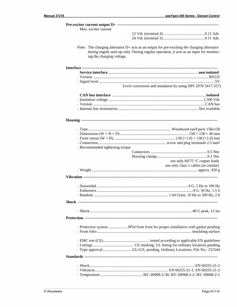
Manual 37218 easYgen-300 Series - Genset Control
© Woodward Page 91/114
Pre-exciter current output D ------------------------------------------------- - Max. exciter current
inal 4) .......................................... 0.11 Adc inal 3) .......................................... 0.11 Adc
Note: The charging alternator D+ acts as an output for pre-exciting the charging alternator
during engine start-up only. During regular operation, it acts as an input for monitor-ing the charging voltage
Interface -------------------------------------------------------------------------------------------------------- .............................................................................................non isolated
.................. ..................................................................RS232 - Signal level .......................................................................................................................5V
L sion and i tion 57)
CAN bus interface ................................................................................................isolated - Insulation voltage .................................................................................................1,500 Vdc - Version ...................................................................................................................CAN bus - Internal line termination .................................................................................. Not available
Housing ---------------------------------------------------------------------------------------------------------
- Type..................................................................................... Woodward easYpack 158x158 - Dimensions (W × H × D) ......................................................................158 × 158 × 40 mm - Front cutout (W × H)............................................................... 138 [+1.0] × 138 [+1.0] mm - Connection...................................................................... screw and plug terminals 2.5 mm² - Recommended tightening torque
Connectors ..........................................................0.5 Nm Housing clamps...................................................0.1 Nm
use only 60/75 °C copper leads use only class 1 cables (or similar)
- Weight ............................................................................................................ approx. 450 g
Vibration -------------------------------------------------------------------------------------------------------
- Sinusoidal ............................................................................................. 4 G, 5 Hz to 100 Hz - Endurance.................................................................................................. 4 G, 30 Hz, 1.5 h - Random ............................................................................ 1.04 Grms, 10 Hz to 500 Hz, 2 h
Shock -----------------------------------------------------------------------------------------------------------
- Shock .........................................................................................................40 G peak, 11 ms
Protection ------------------------------------------------------------------------------------------------------
- Protection system.....................IP54 from front for proper installation with gasket pending - Front folio................................................................................................. insulating surface
- EMC test (CE) ............................................... tested according to applicable EN guidelines - Listings .......................................... CE marking; UL listing for ordinary locations pending - Type approval..............................UL/cUL pending, Ordinary Locations, File No.: 231544
Standards ------------------------------------------------------------------------------------------------------
- Shock ............................................................................................................EN 60255-21-2 - Vibration........................................................................... EN 60255-21-1; EN 60255-21-3 - Temperature............................................ IEC 60068-2-30; IEC 60068-2-2; IEC 60068-2-1
+ -----------------------------
12 Vdc (term24 Vdc (term
.
Service interface
- Version ........... ........................
evel conver nsula by using DPC (P/N 5417-5
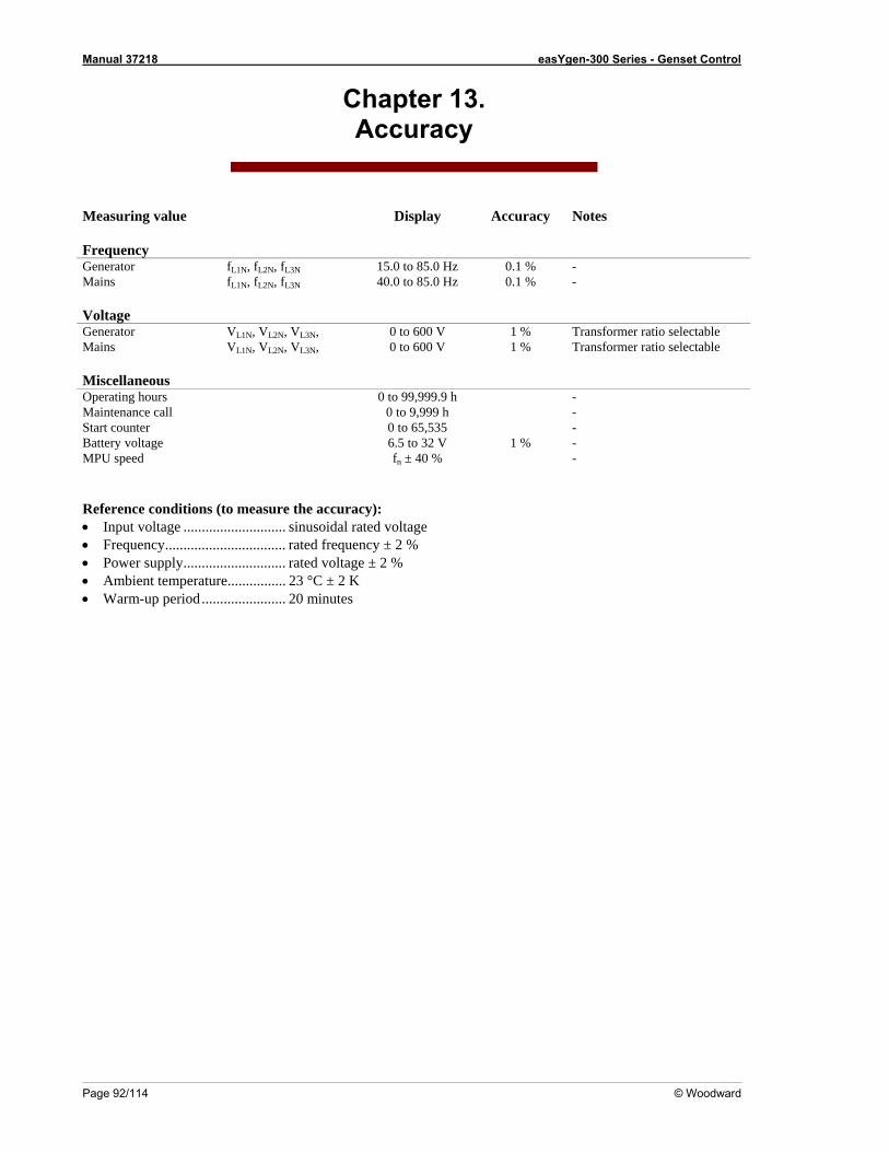
Manual 37218 easYgen-300 Series - Genset Control
Page 92/114 © Woodward
Chapter 13. Accuracy
Measuring value Notes Frequency
enerator fL1N, fL2N, fL3N 15.0 to 85.0 Hz 0.1 % -
Display Accuracy
GMains fL1N, fL2N, fL3 40.0 to 85.0 Hz 0.1 % - Voltage Generator VL1N, VL2N, VL3N, 0 to 600 V 1 % Transformer ratio selectable
N
Mains VL1N, VL2N, VL3N, 0 to 600 V 1 % Transformer ratio selectable Miscellaneo Operating hou -
us rs 0 to 99,999.9 h
Maintenance call 0 to 9,999 h Start counter 0 to 65,535 Batter 6.5 to 32 V 1 % - MPU speed fn ± 40 % -
Power supply............................ rated voltage ± 2 %• Ambient temperature................ 23 °C ± 2 K • Warm-up period....................... 20 minutes
- -
y voltage
Reference conditions (to measure the accuracy): • Input voltage ............................ sinusoidal rated voltage Frequency................................. rated frequency ± 2 % •
•
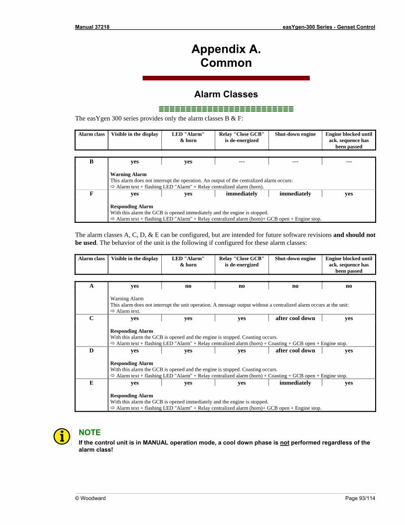
Manual 37218 easYgen-300 Series - Genset Control
© Woodward Page 93/114
Appendix A. Common
Alarm Classes ≡≡≡≡≡≡≡≡≡≡≡≡≡≡≡≡≡≡≡≡≡≡≡≡≡
The easYgen 300 series provides only the alarm classes B & F:
Alarm class Visible in the display LED "Alarm" rn
Relay "Close GCB" is de-energized
Shut-down engine Engine blocked until ack. sequence has
been passed
& ho
B yes yes --- --- ---
Warning Alarm This alarm does not interrupt the operation. An output of the centralized alarm occurs:
Alarm text + flashing LED "Alarm" + Relay centralized alarm (horn). F yes yes immediately immediately yes
Responding Alarm With this alarm the GCB is opened immediately and the engine is stopped.
Alarm text + flashing LED "Alarm" + Relay centralized alarm (horn)+ GCB open + Engine stop. The alarm classes A, C, D, & E can be configured, but are intended for future software revisions and should not be used. The behavior of the unit is the following if configured for these alarm classes:
Alarm class Visible in the display LED "Alarm" & horn
Relay "Close GCB" is de-energized
Shut-down engine Engine blocked until ack. sequence has
been passed
A yes no no no no
Warning Alarm This alarm does not interrupt the unit operation. A message output without a centralized alarm occurs at the unit:
Alarm text. C yes yes yes after cool down yes
Responding Alarm With this alarm the GCB is opened and the engine is stopped. Coasting occurs.
Alarm text + flashing LED "Alarm" + Relay centralized alarm (horn) + Coasting + GCB open + Engine stop. D yes yes yes after cool down yes
Responding Alarm With this alarm the GCB is opened and the engine is stopped. Coasting occurs.
Alarm text + flashing LED "Alarm" + Relay centralized alarm (horn) + Coasting + GCB open + Engine stop. E yes yes yes immediately yes
Responding Alarm With this alarm the GCB is opened immediately and the engine is stopped.
Alarm text + flashing LED "Alarm" + Relay centralized alarm (horn)+ GCB open + Engine stop. NOTE If the control unit is in MANUAL operation mode, a cool down phase is not performed regardless of the alarm class!
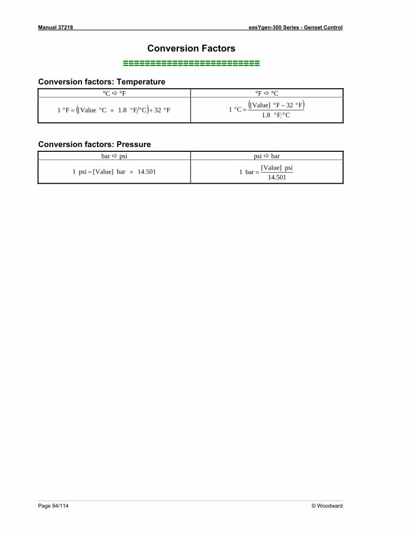
Manual 37218 easYgen-300 Series - Genset Control
Page 94/114 © Woodward
Conversion Factors
Conversion factors: Temperature °C °F °F °C
≡≡≡≡≡≡≡≡≡≡≡≡≡≡≡≡≡≡≡≡≡≡≡≡≡
( )CF8.1
Valu[C1 =°( ) F32CF8. °+°° 1CValue[F1 ×°=°F32F]e
°°°−°
Conversion factors: Pressure bar psi psi bar
501.14psi]Value[bar1 = 501.14× bar]Value[psi1 =
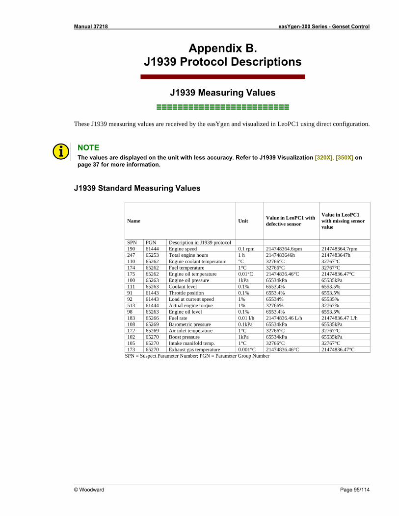
Manual 37218 easYgen-300 Series - Genset Control
© Woodward Page 95/114
Appendix B. J1939 Protocol Descriptions
J1 suring Value≡≡≡≡≡ ≡≡≡≡≡≡≡≡≡
These J1939 measuring values are received by the easYgen a d visualized ation.
939 Mea s ≡≡≡≡≡≡≡≡ ≡≡≡
n in LeoPC1 using direct configur NOTE The values are displayed on the unit with less accuracy. Refer to J1939 Visualiza tion [320X], [350X] on page 37 for more information.
J1939 Standard Measuring Values
Name Unit with Value in LeoPC1 ith missing sensor
Value in LeoPC1 defective sensor w
value
SPN PGN Description in J1939 protocol 190 61444 Engine speed 0.1 rpm 214748364.6rpm 214748364.7rpm 247 65253 Total engine hours 1 h 2147483646h 2147483647h 110 65262 Engine coolant temperature °C 32766°C 32767°C 174 65262 Fuel temperature 1°C 32766°C 32767°C 175 65262 Engine oil temperature 0.01°C 21474836.46°C 21474836.47°C 100 65263 Engine oil pressure 1kPa 65534kPa 65535kPa 111 65263 Coolant level 0.1% 6553,4% 6553.5% 91 61443 Throttle position 0.1% 6553.4% 6553.5% 92 61443 Load at current speed 1% 65534% 65535% 513 61444 Actual engine torque 1% 32766% 32767% 98 65263 Engine oil level 0.1% 6553.4% 6553.5% 183 65266 Fuel rate 0.01 l/h 21474836.46 L/h 21474836.47 L/h 108 65269 Barometric pressure 0.1kPa 65534kPa 65535kPa 172 65269 Air inlet temperature 1°C 32766°C 32767°C 102 65270 Boost pressure 1kPa 65534kPa 65535kPa 105 65270 Intake manifold temp. 1°C 32766°C 32767°C 173 65270 Exhaust gas temperature 0.001°C 21474836.46°C 21474836.47°C
SPN = Suspect Parameter Number; PGN = Parameter Group Number
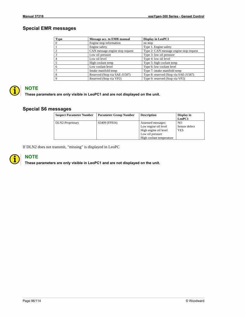
Manual 37218 easYgen-300 Series - Genset Control
Page 96/114 © Woodward
Special EMR messages
Type Message acc. to EMR manual Display in LeoPC1 0 Engine stop information no stop 1 Engine safety Type 1. Engine safety 2 CAN message engine stop request Type 2: CAN message engine stop request 3 Low oil pressure Type 3: low oil pressure 4 Low oil level Type 4: low oil level 5 High coolant temp Type 5: high coolant temp 6 Low coolant level Type 6: low coolant level 7 Intake manifold temp Type 7: intake manifold temp 8 Reserved (Stop via SAE-J1587) Type 8: reserved (Stop via SAE-J1587) 9 Reserved (Stop via VP2) Type 9: reserved (Stop via VP2)
NOTE These parameters are only visible in LeoPC1 and are not displayed on the unit.
Special S6 messages Suspect Parameter Number Parameter Group Number Description Display in
LeoPC1 DLN2-Proprietary 65409 (FF81h) Assessed messages:
Low engine oil level High engine oil level Low oil pressure High coolant temperature
NO Sensor defect YES
If DLN2 does not transmit, "missing" is displayed in LeoPC
NOTE These parameters are only visible in LeoPC1 and are not displayed on the unit.
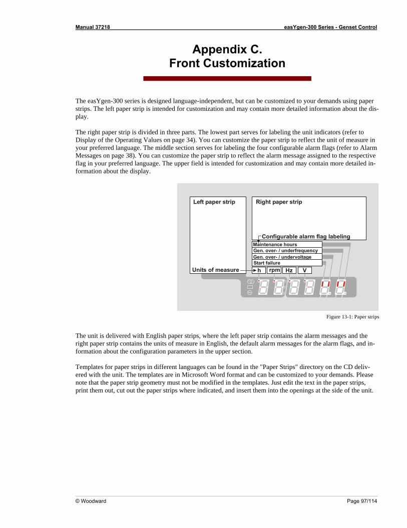
Manual 37218 easYgen-300 Series - Genset Control
© Woodward Page 97/114
Front Customization Appendix C.
The easYgen-300 series is designed language-independent, but can be customized to your demands using paper strips. The left paper strip is intended for customization and may contain more detailed information about the dis-play. The right paper strip is divided in three parts. The lowest part serves for labeling the unit indicators (refer to
isplay of the Operating Values on page 34). You can customize the paper strip to reflect the unit of measure in your preferred language. Th on serves for la configurable al ags (refer to Alarm M You p assigned to the respective flag in your preferred language. The upper field is intend contain more detailed in-formation about the display.
De middle secti beling the four arm fl
essages on page 38). can customize the paper stri to reflect the alarm messageed for customization and may
h rpm Hz V
Maintenance hoursGen. over- / underfrequeGen. over- / undervoltagStart failure
t strip
Units of measure
ncye
Left paper s rip Right paper
Configurable alarm flag labeling
The unit is delivered with En eright paper strip contains the f measure in English, the default alarm messages fo -formation about the configuration parameters in the upper section. Te s in an be found in the "Paper Strips" direr p no metry must not be modified i epri t out the paper strips where indicated, a into the openin e side of the unit.
Figure 13-1: Paper strips
glish paper strips, where th units o
left paper strip contains the alarm messages and the r the alarm flags, and in
mplates for paper strip different languages c ectory on the CD deliv-ed with the unit. The temte that the paper strip geont them out, cu
lates are in Microsoft Word format and can be customized tn the templates. Just edit the tnd insert them
o your demands. Pleasext in the paper strips, gs at th
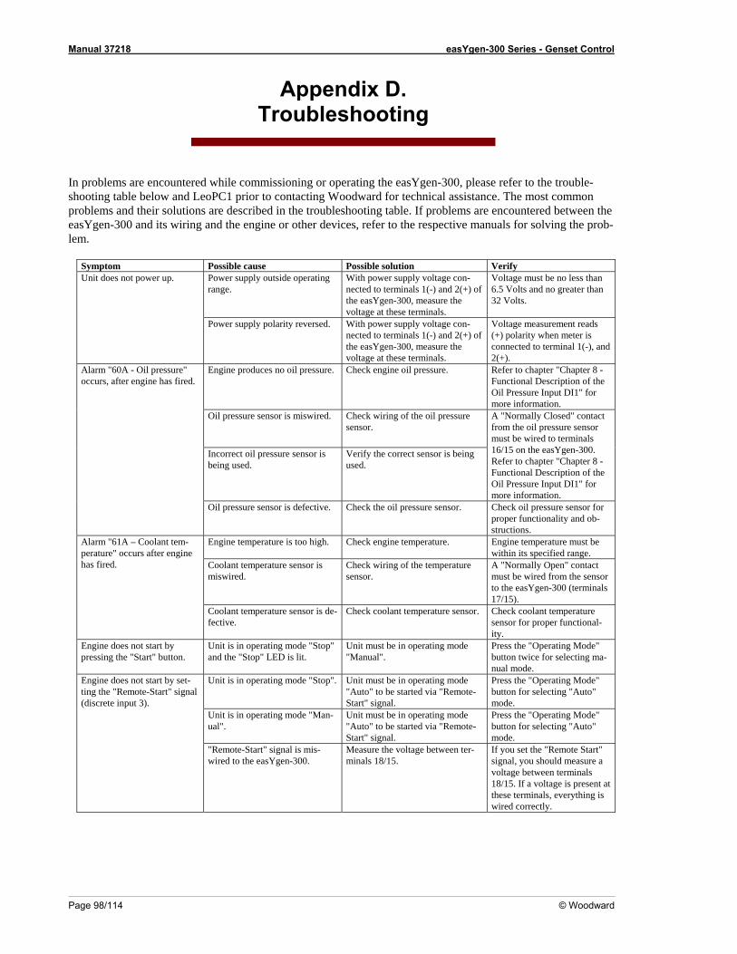
Manual 37218 easYgen-300 Series - Genset Control
Page 98/114 © Woodward
endix D. Troubleshooting
App
In problems are encountered while commissioning or operating the easYgen-300, pleasshooting table below and LeoPC1 prior to contacting Woodward for technical assistancproblems and their solutions are described in the troubleshooting table. If problems areeasYgen-300 and its wiring and the engine or other devices, refer to the respective man -lem.
Symptom Possible
e refer to the trouble-e. The most common
encountered between the uals for solving the prob
Verify cause Possible solution Power supply outside operating range.
With power supply voltage con-nected to terminals 1(-) and 2(+) the easYgen-300, measure the voltage at these terminals.
of Voltage must be no less than 6.5 Volts and no greater than 32 Volts.
Unit does not power up.
Power supply polarity reversed. With power supply voltage con-nected to terminals 1(-) and 2(+) of the easYgen-300, measure the voltage at these terminals.
Voltage measurement reads (+) polarity when meter is connected to terminal 1(-), and 2(+).
Engine produces no oil pressure. Check engine oil pressure. Refer to chapter "Chapter 8 - Functional Description of the Oil Pressure Input DI1" for more information.
Oil pressure sensor is miswired. .
Check wiring of the oil pressure sensor
Incorrect oil pressure sensor is being used.
Verify the correct sensor is being used.
A "Normally Closed" contact from the oil pressure sensor must be wired to terminals 16/15 on the easYgen-300. Refer to chapter "Chapter 8 - Functional Description of the Oil Pressure Input DI1" for more information.
Alarm "60A - Oil pressure" occurs, after engine has fired.
Oil pressure sensor is defective. Check the oil pressure sensor. Check oil pressure sensor for proper functionality and ob-structions.
Engine temperature is too high. Check engine temperature. Engine temperature must be within its specified range.
Coolant temperature sensor is miswired.
Check wiring of the temperature sensor.
A "Normally Open" contact must be wired from the sensorto the easYgen-300 (terminals 17/15).
Alarm "61A – Coolant tem-perature" occurs after engine has fired.
is de-fective. Coolant temperature sensor Check coolant temperature sensor. Check coolant temperature
sensor for proper functional-ity.
Engine does not start by pressing the "Start" button.
Unit is in operating mode "Stop" and the "Stop" LED is lit.
Unit must be in operating mode "Manual". a-
nual mode.
Press the "Operating Mode" button twice for selecting m
Unit is in operating mode "Stop". Unit must be in operating mode "Auto" to be started via "Remote-Start" signal.
Press the "Operating Mode" button for selecting "Auto" mode.
Unit is in operating mode "Man-ual".
Unit must be in operating mode "Auto" to be started via "Remote-Start" signal.
Press the "Operating Mode" button for selecting "Auto" mode.
Engine does not start by set-ting the "Remote-Start" signal (discrete input 3).
"Remote-Start" signal is mis-wired to the easYgen-300.
Measure the voltage between ter-minals 18/15.
If you set the "Remote Start" signal, you should measure a voltage between terminals 18/15. If a voltage is present at these terminals, everything is wired correctly.
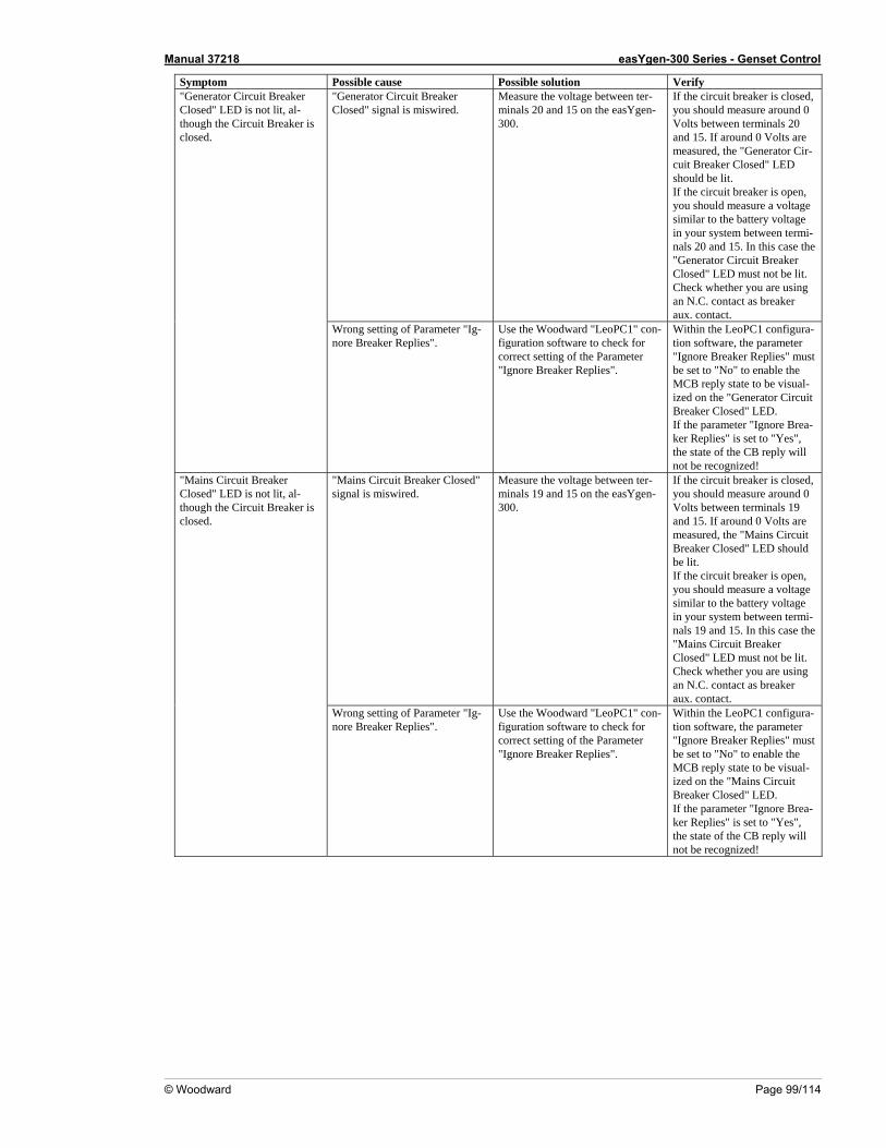
Manual 37218 easYgen-300 Series - Genset Control
© Woodward Page 99/114
Symptom Possible Verify cause Possible solution "Generator Circuit Breaker Closed" signal is miswired. on the easYgen-
300.
If the circuit breaker is closed, you should measure around 0 Volts between terminals 20
nerator Cir-
circuit breaker is open,
ge system between termi-
als 20 and 15. In this case the "Generator Circuit Breaker Closed" LED must not be lit. Check whether you are using an N.C. contact as breaker
Measure the voltage between ter-minals 20 and 15
and 15. If around 0 Volts are measured, the "Gecuit Breaker Closed" LED should be lit. If the you should measure a voltage similar to the battery voltain your n
aux. contact.
"Generator Circuit Breaker Closed" LED is not lit, al-though the Circuit Breaker is closed.
Wrong setting of Parameter "Ig-nore Breaker Replies".
Use the Woodward "LeoPC1" con-figuration software to check for correct setting of the Parameter "Ignore Breaker Replies".
eplies" must e set to "No" to enable the
cuit Closed" LED.
the parameter "Ignore Brea-
Within the LeoPC1 configura-tion software, the parameter "Ignore Breaker RbMCB reply state to be visual-ized on the "Generator CirBreakerIfker Replies" is set to "Yes", the state of the CB reply will not be recognized!
"Mains Circuit Breaker Closed" signal is miswired.
Measure the voltage between ter-minals 19 and 15 on the easYgen-300.
rcuit breaker is closed,
cuit
easure a voltage
e eaker
If the ciyou should measure around 0 Volts between terminals 19 and 15. If around 0 Volts are measured, the "Mains CirBreaker Closed" LED should be lit. If the circuit breaker is open, you should msimilar to the battery voltage in your system between termi-nals 19 and 15. In this case th"Mains Circuit BrClosed" LED must not be lit. Check whether you are usingan N.C. contact as breaker aux. contact.
"Mains Circuit Breaker Closed" LED is not lit, al-though the Circuit Breaker is closed.
Wrong setting of Parameter "Ig-nore Breaker Replies".
Use the Woodward "LeoPC1" con-figuration software to check for
-meter
eply state to be visual-
correct setting of the Parameter "Ignore Breaker Replies".
Within the LeoPC1 configuration software, the para"Ignore Breaker Replies" must be set to "No" to enable the MCB rized on the "Mains Circuit Breaker Closed" LED. If the parameter "Ignore Brea-ker Replies" is set to "Yes", the state of the CB reply will not be recognized!
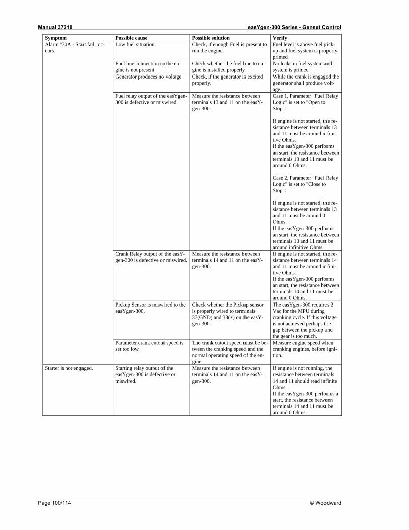
Manual 37218 easYgen-300 Series - Genset Control
Page 100/114 © Woodward
Verify Symptom Possible cause Possible solution Low fuel situation. Check, if enough Fuel is present to
run the engine. Fuel level is above fuel pick-up and fuel system is properly primed
Fuel line connection to the en-gine is not present.
whether the fuel line to en-gine is installed properly.
No leaks in fuel system and system is primed
Check
Generator produces no voltage. Check, if the generator is excited While the crank is engaged the properly. generator shall produce volt-
age. Fuel relay output of the easYgen-300 is defective or miswired.
Measure the resistance between terminals 13 and 11 on the easY-gen-300.
ust be around infini-tive Ohms.
If engine is not started, the re-sistance between terminals 13 and 11 must be around 0 Ohms.
the easYgen-300 performs e resistance between 3 and 11 must be
around infinitive Ohms.
Case 1, Parameter "Fuel Relay Logic" is set to "Open to Stop": If engine is not started, the re-sistance between terminals 13 and 11 m
If the easYgen-300 performsan start, the resistance between terminals 13 and 11 must bearound 0 Ohms. Case 2, Parameter "Fuel Relay Logic" is set to "Close to Stop":
Ifan start, thterminals 1
Crank Relay output of the easY-gen-300 is defective or miswired.
Measure the resistance between terminals 14 and 11 on the easY-gen-300.
s not started, the re-stance between terminals 14
-300 performs n start, the resistance between
If engine isiand 11 must be around infini-tive Ohms. If the easYgenaterminals 14 and 11 must be around 0 Ohms.
Pickup Sensor is miswired to the Check whether the Pickup sensor
gen-300.
2 Vac for the MPU during cranking cycle. If this voltage is not achieved perhaps the gap between the pickup and the gear is too much.
easYgen-300. is properly wired to terminals 37(GND) and 38(+) on the easY-
The easYgen-300 requires
Alarm "30A - Start fail" oc-curs.
Parameter crank cutout speed is set too low
The crank cutout speed must be be-tween the cranking speed and the normal operating speed of the en-gine
Measure engine speed when cranking engines, before igni-tion.
Starter is not engaged. Starting relay output of the easYgen-300 is defective or miswired.
Measure the resistance between terminals 14 and 11 on the easY-gen-300.
If engine is not running, the resistance between terminals 14 and 11 should read infinite Ohms. If the easYgen-300 performs a start, the resistance between terminals 14 and 11 must be around 0 Ohms.
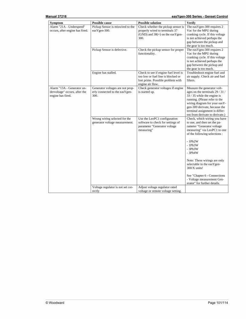
Manual 37218 easYgen-300 Series - Genset Control
© Woodward Page 101/114
Verify Symptom Possible cause Possible solution Pickup Sensor is miswired to theeasYgen-300.
- e
Check whether the pickup sensor isproperly wired to terminals 37 (GND) and 38(+) on the easYgen300.
The easYgen-300 requires 2 Vac for the MPU during cranking cycle. If this voltagis not achieved perhaps the gap between the pickup and the gear is too much.
Pickup Sensor is defective. Check the pickup sensor for proper functionality.
e. If this voltage
ch.
The easYgen-300 requires 2 Vac for the MPU during cranking cyclis not achieved perhaps the gap between the pickup and the gear is too mu
Alarm "21A - Underspeed" occurs, after engine has fired.
e. Possible problem with engine air flow.
Troubleshoot engine fuel and air supply. Check air and fuel filters.
Engine has stalled. Check to see if engine fuel level is too low or fuel line is blocked or lost prim
Generator voltages are not prop-erly connected to the easYgen-300.
e
g. (Please refer to the -
ivate.)
Check generator voltages if enginis started up.
Measure the generator volt-ages on the terminals 29 / 31 / 33 / 35 while the engine is runninwiring diagram for your easYgen-300 derivate, because theterminal assignment is differ-ent from derivate to der
Wrong wiring selected for the generator voltage measurement.
parameter "Generator voltage measuring"
Check, which wiring you have to use, and then set the pa-rameter "Generator voltage measuring" via LeoPC1 to one
- 1Ph3W
- 3Ph4W
or further details.
Use the LeoPC1 configuration software to check for settings of
of the following selections :
- 1Ph2W
- 3Ph3W
Note: These wirings are only selectable in the easYgen-300/X units! See "Chapter 6 - Connections - Voltage measurement Gen-erator" f
Alarm "13A - Generator un-dervoltage" occurs, after the engine has fired.
r- Voltage regulator is not set corectly
Adjust voltage regulator rated voltage or remote voltage setting.
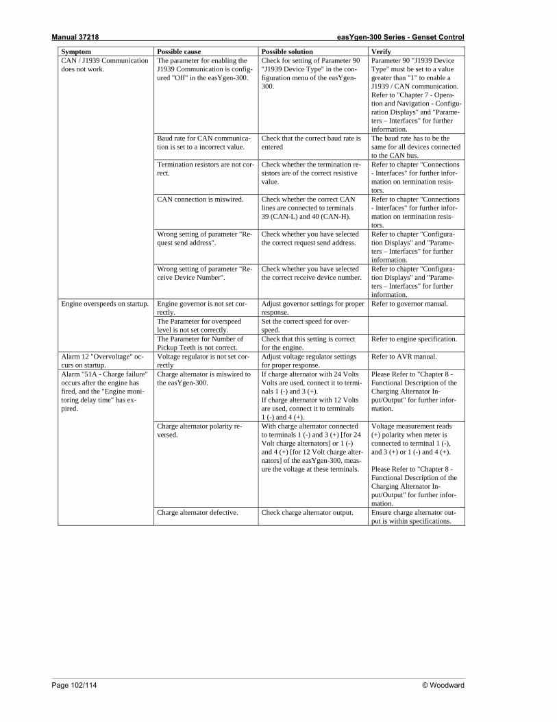
Manual 37218 easYgen-300 Series - Genset Control
Page 102/114 © Woodward
Symptom Possible cause Possible solution Verify The parameter for J1939 Communicaured "Off"
of Parameter 90 pe" in the con-
Ygen-
Parameter 90 "J1939 Device Type" must be set to a value greater than "1" to enable a J1939 / CAN communication. Refer to "Chapter 7 - Opera-
Configu-e-
enabling the tion is config-
in the easYgen-300.
Check for setting "J1939 Device Tyfiguration menu of the eas300.
tion and Navigation -ration Displays" and "Paramters – Interfaces" for further information.
Baud rate for CAN communica- Check that the correct baud rate is The baud rate has to be the tion is set to a incorrect value. entered same for all devices connected
to the CAN bus. Termination resistors are not cor-rect.
Check whether the termination re-sistors are of the correct resistive
Refer to chapter "Connections - Interfaces" for further infor-
value. mation on termination resis-tors.
CAN connection is m ed. lines are connected to terminals
L) and 40 (C
- Interfaces" for further infor-
ation on termination resis-tors.
iswir eck whether the correct CAN Refer to chapter "ConnectionsCh
39 (CAN- AN-H). m
Wrong setting of parameter "Re-d address".
Check whether you have selected ect request send ad
Refer to chapter "Config ra-tion Displays" and "Parame-ters – Inte or further information.
quest sen the corr dress. u
rfaces" f
CAN / J1939 Communication does not work.
ng setting of parameter "Re-ber".
Check whether you have srrect receive device number.
Refer to chapter "Config a-tion Displays" and ters foinfor
Wroceive Device Num
elected the co
ur"Parame-r further – Interfaces"
mation. Engine governor is not set cor- t governor settings for proper
Refer r m
rectly. Adjusresponse.
to governo anual.
The Parameter for overspeed level is not set correctly.
correct speed for o
Set the ver-speed.
Engine overspeeds on startup.
eter for Number of eth is not correct.
that this setting is c engine.
Refer pecification. The ParamPickup Te
Check orrect for the
to engine s
Alarm 12 "Overvoltage" oc- Voltage regulator is not set cor- Adjust voltage regulator settings response.
Refe ncurs on startup. rectly for proper
r to AVR ma ual.
Charge alternator is miswired to the easYgen-300.
If charge alternator with 24 Volts Volts are used, connect it to termi-
-) and 3 (+). lternator with 1onnect it to term (+).
Please Refer to "Chapter 8 - Functional Description of the Char In-put/Outpu or further infor-mation.
nals 1 (If charge a 2 Volts are used, c1 (-) and 4
inals
ging Alternatort" f
Charge alternator polarity re-ed.
With charge alternator connected to terminals 1 (-) and 3 (+) [for 24 Volt charge alternators] or 1 (-)
Volt csYgen-
voltage at these term .
Voltage measure ent reads (+) polarity when meter is connected terminal 1 (-), and 3 (+) or 1 (-) and Please Refer to "Chapter 8 - Functional Description of the Charging Alternator In-put/Outpu or further in or-mation.
vers
and 4 (+) [for 12nators] of the ea
harge alter-300, meas-
ure the inals
m
to 4 (+).
t" f f
Alarm "51A - Charge failure" occurs after the engine has
and the "Engine moni-firetori
Charge alternator defective. ge alternator Ensur ternator out-put is within specifications.
d, ng delay time" has ex-
pired.
Check char output. e charge al
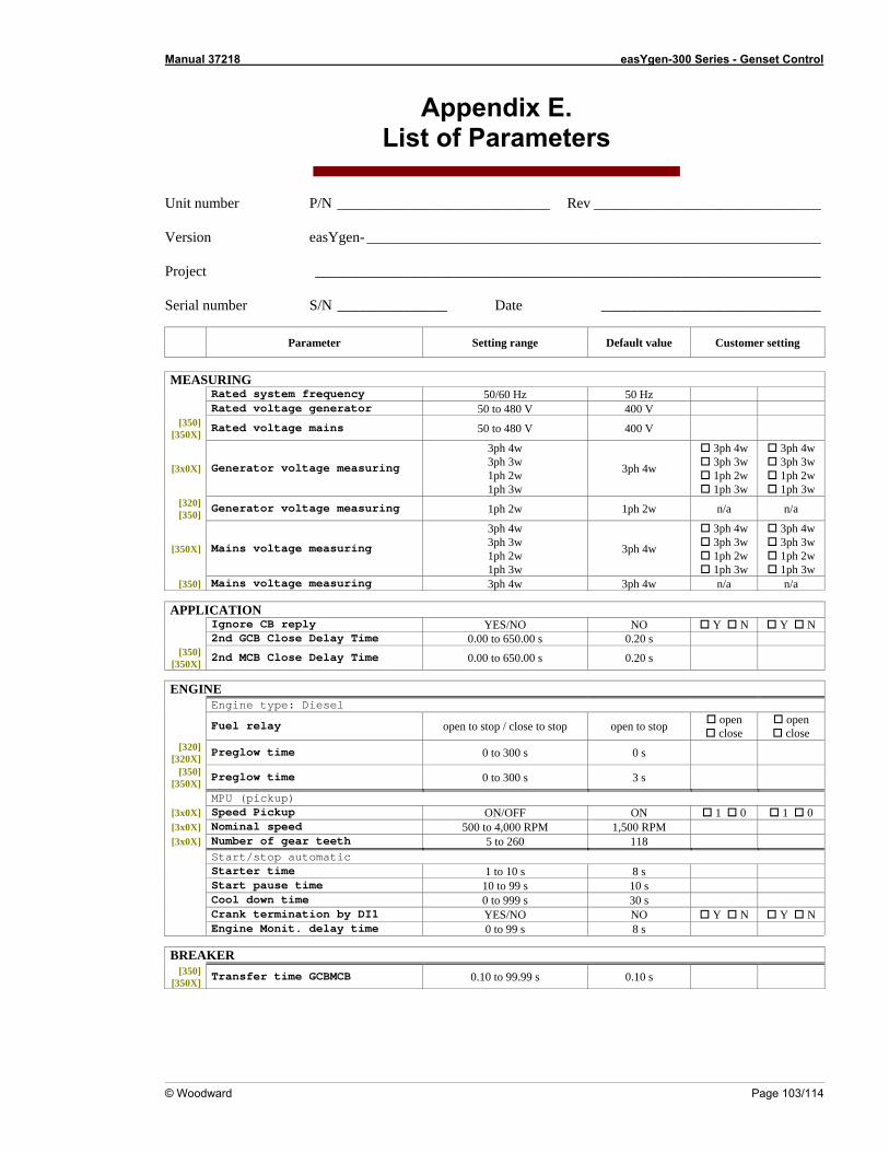
Manual 37218 easYgen-300 Series - Genset Control
© Woodward Page 103/114
Appendix E. List of Parameters
U __________________________ Rev _______________________________
easYgen- ______________________________________________________________ Projec _____________________________________________________________________ Serial _______ ______________________________
Parameter Defa lue Customer setting
nit number P/N ___
Version
t
number S/N ________ Date
Setting range ult va
MEASURING
50/60 Hz 50 Hz Rated system frequency Rated voltage generator 50 to 480 V 400 V
[350] [350X
oltage mains 50 to 480 V 400 V ] Rated v
[3x0X ng
3ph 4w 3ph 3w 1ph 2w 1ph 3w
3ph 4w
3ph 4w 3ph 3w 1ph 2w 1ph 3w
3ph 4w 3ph 3w 1ph 2w 1ph 3w
] Generator voltage measuri
[320] [350]
ltage measuring n/a Generator vo 1ph 2w 1ph 2w n/a
[350X] uring
3ph 4w 3ph 3w 1ph 2w 1ph 3w
3ph 4w
3ph 4w 3ph 3w 1ph 2w 1ph 3w
3ph 4w 3ph 3w 1ph 2w 1ph 3w
Mains voltage meas
[350] Mains voltage measuring 3ph 4w 3ph 4w n/a n/a
APPL CATIOI N Ignore CB reply Y N Y N YES/NO NO 2nd GCB Close Delay Time 0.00 to 650.00 s 0.2 s 0
[350] [350X]
y Time 0.00 to 650.00 s 0 2nd MCB Close Dela .20 s
ENGINE Engine type: Diesel
Fuel relay open to stop / close to stop open to stop open close
open close
[320] [320X]
Preglow time 0 to 300 s 0 s [350]
[350X] Preglow time 0 to 300 s 3 s
MPU (pickup) Speed Pickup ON/OFF ON 0 0 1 1 [3x0X]
[3x0X 500 to 4, 0 RPM 1,500 RPM Nominal speed 00 ] [ 118 Number of gear teeth 5 to 260 3x0X]
Start/stop automatic Starter time 1 to 10 s 8 s Start pause time 10 to 99 s 10 s Cool down time 0 to 999 s 30 s Crank termination by DI1 YES/NO NO Y N Y N Engine Monit. delay time 0 to 99 s 8 s
BREAKER
[350] [350X]
Transfer time GCBMCB 0.10 to 99.99 s 0.10 s
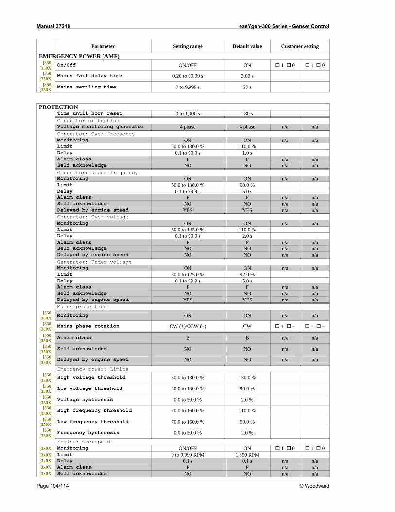
Manual 37218 easYgen-300 Series - Genset Control
Page 104/114 © Woodward
Setting range Default value Customer setting
Parameter
EMERGENCY POWER (AMF) [350 ON/OFF ON 0 0 ]
[350X] On/Off 1 1
[350] [350X]
Mains fail delay time 0. 20 to 99.99 s 3.00 s [350]
[350X] Mains settling time 0 to 99 s 20 s 9,9
PROTECTION Time until horn reset 0 t s o 1,000 180 s Generator protection Voltage monitoring generator 4 phase 4 phase n/a n/a Generator: Over frequency Monitoring ON ON n/a n/a 50.0 to 130.0 % 1 Limit 10.0 % Delay 0.1 to 99.9 s 1. s 0 Alarm class F F n/a n/a Self acknowledge NO NO n/a n/a Generator: Under frequency Monitoring ON ON n/a n/a Limit 5 0.0 to 130.0 % 90.0 % 0.1Delay to 99.9 s 5.0 s Alarm class F F n/a n/a Self acknowledge NO NO n/a n/a Delayed by engine speed YES YES n/a n/a Generator: Over voltage Monitoring ON ON n/a n/a Limit 5 0.0 to 125.0 % 110.0 % 0.1Delay to 99.9 s 2.0 s Alarm class F F n/a n/a Self acknowledge NO NO n/a n/a Delayed by engine speed NO NO n/a n/a Generator: Under voltage Monitoring ON ON n/a n/a Limit 50.0 to 125.0 % 92.0 % Delay 0.1 to 99.9 s 5. 0 s Alarm class F F n/a n/a Self acknowledge NO NO n/a n/a Delayed by engine speed YES YES n/a n/a Mains protection
[350] [350X]
Monitoring ON ON n/a n/a [350]
[350X] Mains phase rotation CW (+)/CCW (–) CW + – + –
[350] [350X]
Alarm class B B n/a n/a [350]
[350X] Self acknowledge NO NO n/a n/a
[350] [350X]
Delayed by engine speed NO NO n/a n/a
Emergency power: Limits [350]
[350X] High voltage threshold 50.0 to 130.0 % 130.0 %
[350] [350X]
Low voltage threshold 50.0 to 130.0 % 90.0 % [350]
[350X] Voltage hysteresis 0.0 to 50.0 % 2.0 %
[350] [350X]
High frequency threshold 70.0 to 160.0 % 110.0 % [350]
[350X] Low frequency threshold 70.0 to 160.0 % 90.0 %
[350] [350X]
Frequency hysteresis 0.0 to 50.0 % 2.0 %
Engine: Overspeed [3x0X] Monitoring ON/OFF ON 1 0 1 0 [3x0X] Limit 0 to 9,999 RPM 1,850 RPM [3x0X] Delay 0.1 s 0.1 s n/a n/a [3x0X] Alarm class F F n/a n/a [3x0X] Self acknowledge NO NO n/a n/a
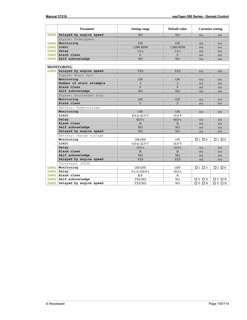
Manual 37218 easYgen-300 Series - Genset Control
© Woodward Page 105/114
Parameter Setting range Default value Customer setting
[3x0X] Delayed by engine speed NO NO n/a n/a Engine: Underspeed
[3x0X] Monitoring ON ON n/a n/a [3x0X] Limit 1,000 RPM 1,000 RPM n/a n/a [3x0X] Delay 1. 0 s 1. 0 s n/a n/a [3x0X] Alarm class F F n/a n/a [3x0X] Self acknowledge NO NO n/a n/a
MONITORING [3x0X] Delayed by engine speed YES YES n/a n/a
Engine: Start fail Monitoring ON ON n/a n/a
Number of start attempts 3 3 n/a n/a Alarm class F F n/a n/a Self acknowledge NO NO n/a n/a
Engine: Unintended stop Monitoring ON ON n/a n/a
Alarm class F F n/a n/a Battery: Undervoltage Monitoring ON ON n/a n/a Limit 8.0 to 42.0 V 10.0 V
Delay 60.0 s 60.0 s n/a n/a Alarm class B B n/a n/a Self acknowledge NO NO n/a n/a Delayed by engine speed NO NO n/a n/a
Battery: charge voltage Monitoring ON/OFF ON 1 0 1 0
.. Limit 0.0 to 32.0 V 16.0 V Delay 10.0 s 10.0 s n/a n/a Alarm class B B n/a n/a Self acknowledge NO NO n/a n/a Delayed by engine speed YES YES n/a n/a
Interface: J1939 [3x0X 1 0 ] Monitoring ON/OFF OFF 1 0 [3x0X] 0. s Delay 1 to 650.0 20.0 s [3x0X] arm class B/F B Al [3x0X] Self acknowledge YES/NO NO Y N Y N [3x0X] Delayed by engine speed YES/NO NO Y N Y N
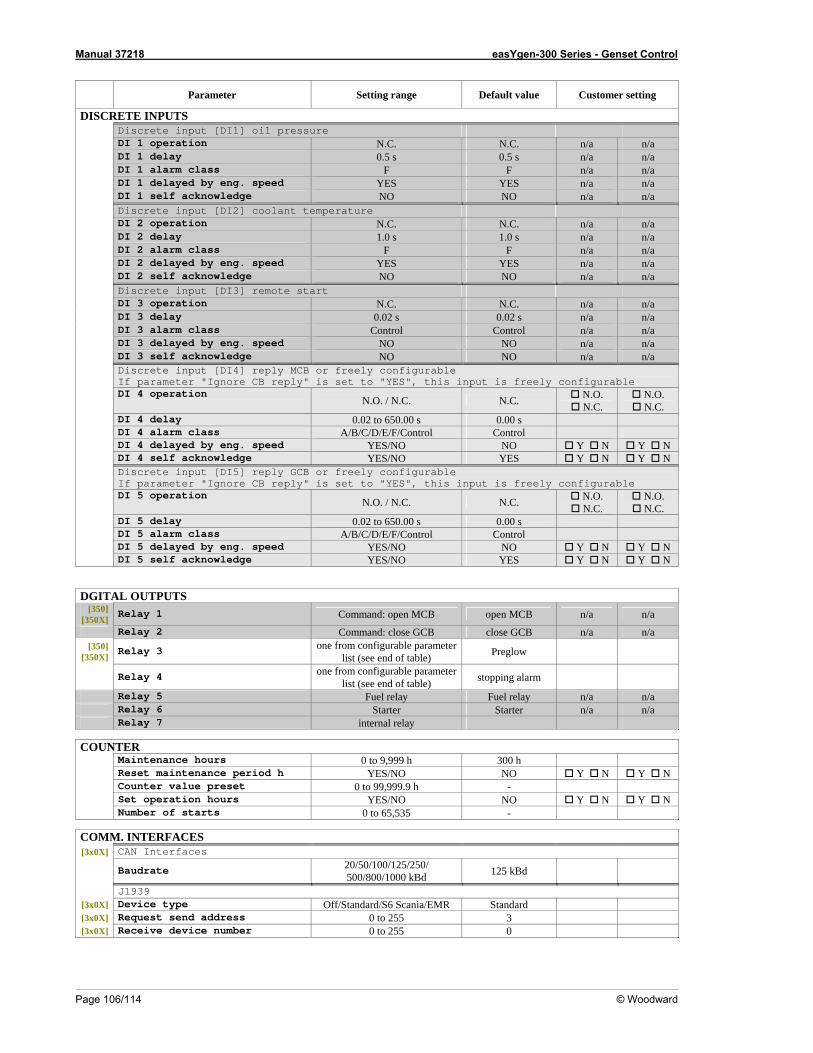
Manual 37218 easYgen-300 Series - Genset Control
Page 106/114 © Woodward
Parameter Setting range Default value Customer setting
DISCRETE INPUTS Discrete input [DI1] oil pressure DI 1 operation N.C. N.C. n/a n/a DI 1 delay 0. s 5 0. s 5 n/a n/a DI 1 alarm class F F n/a n/a DI 1 delayed by eng. speed YES YES n/a n/a DI 1 self acknowledge NO NO n/a n/a Discrete input [DI2] coolant temperature DI 2 operation N.C. N.C. n/a n/a DI 2 delay 1.0 s 1.0 s n/a n/a DI 2 alarm class F F n/a n/a DI 2 delayed by eng. speed YES YES n/a n/a DI 2 self acknowledge NO NO n/a n/a Discrete input [DI3] remote start DI 3 operation N.C. N.C. n/a n/a DI 3 delay 0.02 s 0.02 s n/a n/a DI 3 alarm class Control C l ontro n/a n/a DI 3 delayed by eng. speed NO NO n/a n/a DI 3 self acknowledge NO NO n/a n/a
Discrete input [DI4] reply MCB or freel gurable y confiIf parameter "Ignore CB reply" is set to "YES", this input i eely c bs fr onfigura le
DI 4 operation
N.O. / N.C. N.C. N.O. N.C.
N.O. N.C.
DI 4 delay 0.0 s 2 to 650.00 0.00 s DI 4 alarm class A/B/C/D/E/F/Control C l ontro DI 4 delayed by eng. speed YES/NO NO Y N Y N DI 4 self acknowledge YES/NO YES Y N Y N
Discrete input [DI5] reply GCB or freely configurable If parameter "Ignore CB reply" is set to "YES", this input i eely c bs fr onfigura le
DI 5 operation
N.O. / N.C. N.C. N.O. N.C.
N.O. N.C.
DI 5 delay 0.0 s 2 to 650.00 0.00 s DI 5 alarm class A/B/C/D/E/F/Control C l ontro DI 5 delayed by eng. speed YES/NO NO Y N Y N DI 5 self acknowledge YES/NO YES Y N Y N
DGITAL OUTPUTS [350]
[350X] Relay 1 Comm MCB and: open open MCB n/a n/a
Relay 2 Comm GCB and: close close GCB n/a n/a [350
[350X] one from configurable parameter
list (see end of table) P ] Relay 3 reglow
Relay 4 one from configurable parameter list (see end of table) stopping alarm
Relay 5 Fuel relay Fuel relay n/a n/a Relay 6 Starter Starter n/a n/a Relay 7 internal relay
COUNTER
Maintenance hours 0 to 9,999 h 300 h Reset maintenance period h YES/NO NO Y N Y N Counter value preset 0 to 99,999.9 h - Set operation hours YES/NO NO Y N Y N Number of starts 0 to 65,535 -
COMM. INTERFACES [3x0X] CAN Interfaces
Baudrate 20/50/100/125/250/ 500/800/1000 kBd 125 kBd
J1939 [3x0X] Device type Off/Standard/S6 Scania/EMR Standard [3x0X] Request send address 0 to 255 3 [3x0X] Receive device number 0 to 255 0
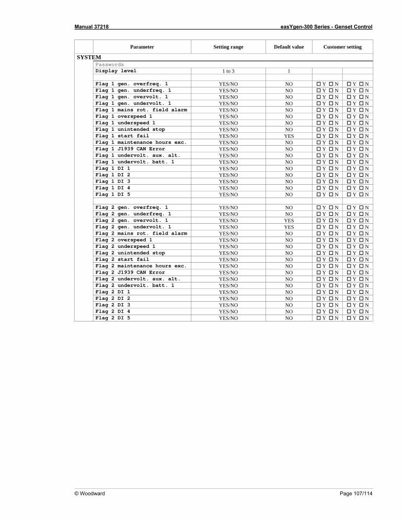
Manual 37218 easYgen-300 Series - Genset Control
© Woodward Page 107/114
Parameter Setting range Default value Customer setting
SYSTEM Passwords Display level 1 to 3 1 Flag 1 gen. overfreq. 1 YES/NO NO Y N Y N Flag 1 gen. underfreq. 1 YES/NO NO Y N Y N Flag 1 gen. overvolt. 1 YES/NO NO Y N Y N Flag 1 gen. undervolt. 1 YES/NO NO Y N Y N alarm Y N Flag 1 mains rot. field YES/NO NO Y N Flag 1 overspeed 1 YES/NO NO Y N Y N Flag 1 underspeed 1 Y N YES/NO NO Y N Flag 1 unintended stop Y N Y N YES/NO NO Flag 1 start fail YES/NO YES Y N Y N Flag 1 maintenance hours exc. YES/NO NO Y N Y N Flag 1 J1939 CAN Error YES/NO NO Y N Y N Flag 1 undervolt. aux. alt. YES/NO NO Y N Y N olt. batt. 1 Flag 1 underv YES/NO NO Y N Y N Flag 1 DI 1 YES/NO NO Y N Y N Y N Flag 1 DI 2 YES/NO NO Y N Flag 1 DI 3 YES/NO NO Y N Y N YES/NO NO Y N Y N Flag 1 DI 4 Flag 1 DI 5 YES/NO NO Y N Y N Flag 2 gen. overfreq. 1 YES/NO NO Y N Y N Y N Flag 2 gen. underfreq. 1 YES/NO NO Y N Flag 2 gen. overvolt. 1 YES/NO YES Y N Y N t. 1 Flag 2 gen. undervol YES/NO YES Y N Y N alarm NO Flag 2 mains rot. field YES/NO Y N Y N Y N Y N Flag 2 overspeed 1 YES/NO NO Flag 2 underspeed 1 YES/NO NO Y N Y N NO Y N Y N Flag 2 unintended stop YES/NO NO Flag 2 start fail YES/NO Y N Y N Flag 2 maintenance hours exc. NO Y N Y N YES/NO Flag 2 J1939 CAN Error YES/NO NO Y N Y N olt. aux. alt. NO Y N Y N Flag 2 underv YES/NO Flag 2 undervolt. batt. 1 NO YES/NO Y N Y N Y N Flag 2 DI 1 YES/NO NO Y N NO Y N Flag 2 DI 2 YES/NO Y N Flag 2 DI 3 YES/NO NO Y N Y N ag 2 DI 4 YES/NO NO Y N Y N Fl YES/NO NO Y N Y N Flag 2 DI 5
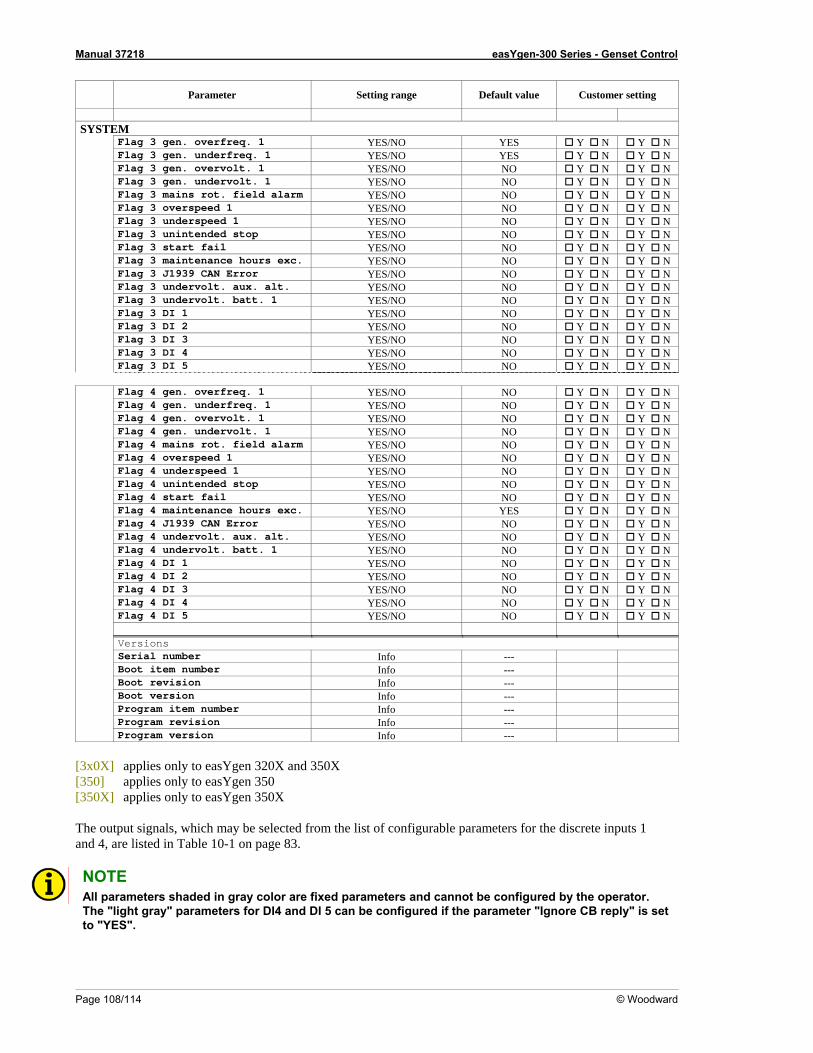
Manual 37218 easYgen-300 Series - Genset Control
Page 108/114 © Woodward
Parameter Setting range Default value Customer setting
SYSTEM
Flag 3 gen. overfreq. 1 YES/NO YES Y N Y N Flag 3 gen. underfreq. 1 YES/NO YES Y N Y N Flag 3 gen. overvolt. 1 YES/NO NO Y N Y N Flag 3 gen. undervolt. 1 YES/NO NO Y N Y N Flag 3 mains rot. field alarm YES/NO NO Y N Y N Flag 3 overspeed 1 YES/NO NO Y N Y N Flag 3 underspeed 1 Y N Y N YES/NO NO Flag 3 unintended s Y N Y N top YES/NO NO Flag 3 start fail Y N Y N YES/NO NO Flag 3 maintenance hours exc. YES/NO NO Y N Y N Flag 3 J1939 CAN Error YES/NO NO Y N Y N Flag 3 undervolt. aux. alt. YES/NO NO Y N Y N Flag 3 undervolt. batt. 1 YES/NO NO Y N Y N Flag 3 DI 1 YES/NO NO Y N Y N Flag 3 DI 2 YES/NO NO Y N Y N Flag 3 DI 3 YES/NO NO Y N Y N Flag 3 DI 4 YES/NO NO Y N Y N Flag 3 DI 5 YES/NO NO Y N Y N Flag 4 gen. overfreq. 1 YES/NO NO Y N Y N Flag 4 gen. underfreq. 1 YES/NO NO Y N Y N Flag 4 gen. overvolt. 1 YES/NO NO Y N Y N Flag 4 gen. undervolt. 1 YES/NO NO Y N Y N Flag 4 mains rot. field alarm Y N Y N YES/NO NO Flag 4 overspeed 1 Y N Y N YES/NO NO Flag 4 underspeed 1 Y N Y N YES/NO NO Flag 4 unintended stop YES/NO NO Y N Y N Flag 4 start fail YES/NO NO Y N Y N Flag 4 maintenance hours exc. YES/NO YES Y N Y N Flag 4 J1939 CAN Error YES/NO NO Y N Y N Flag 4 undervolt. aux. alt. YES/NO NO Y N Y N Flag 4 undervolt. batt. 1 YES/NO NO Y N Y N Flag 4 DI 1 YES/NO NO Y N Y N Flag 4 DI 2 YES/NO NO Y N Y N Flag 4 DI 3 YES/NO NO Y N Y N Flag 4 DI 4 YES/NO NO Y N Y N Flag 4 DI 5 YES/NO NO Y N Y N Versions Serial number Info --- Boot item number Info --- Boot revision Info --- Boot version Info --- Program item number Info --- Program revision Info --- Program version Info ---
[3x0X] applies only to easYgen 320X and 350X [350] applies only to easYgen 350 [350X] applies only to easYgen 350X The output signals, which may be selected from the list of configurable parameters for the discrete inputs 1 and 4, are listed in Table 10-1 on page 83.
NOTE All parameters shaded in gray color are fixed parameters and cannot be configured by the operator. The "light gray" parameters for DI4 and DI 5 can be configured if the parameter "Ignore CB reply" is set to "YES".
Manual 37218 easYgen-300 Series - Genset Control
© Woodward Page 109/114
Appendix F. Service Options
Product Service Options ≡≡≡≡≡≡≡≡≡≡≡≡≡≡≡≡≡≡≡≡≡≡≡≡≡
icing Woodward equipment, based on the standard Wood-ward Product and Service Warranty (5-01-1205) that is in effect at the time the product is purchased from Woodward or the service is performed. If you are experiencing problems with installation or unsatisfactory per-formance of an installed system, the following options are available: • Consult the troubleshooting guide in the manual. Contact Woodward technical assistance (see "How to Contact Woodward" later in this chapter) and discuss
your problem. In most cases, your problem can be resolved over the phone. If not, you can select which f action you wish to pursue based on the available services listed in this section.
≡≡≡≡≡≡≡≡≡≡≡≡≡≡≡≡≡≡≡≡≡≡≡≡≡ If a control (or any part of an electronic c ward for repair, please contact Wood-ward in advance to obtain a Re s), attach a tag with the fol-lowing information:
• name and phone number of contact person; (S/N);
• description of the problem; instructions describing the desired type of repair.
The following factory options are available for serv
•
course o
Returning Equipment For Repair
ontrol) is to be returned to Woodturn Authorization Number. When shipping the unit(
• name and location where the control is installed;
• complete Woodward part numbers (P/N) and serial number
•
CAUTION To prevent damage to electronic components caused by improper handling, read and observe the pre-cautions in Woodward manual 82715, Guide for Handling and Protection of Electronic Controls, Printed Circuit Boards, and Modules.
Manual 37218 easYgen-300 Series - Genset Control
Page 110/114 © Woodward
Packing a Control Use the following materials wh • protective caps on any connectors
packing mindustry-approved packing material
on for increased strength
eturn r N When returning equipment to Woodward, please telephone and ask for the Customer Service Department in Stuttgart [+49 (0) 711 789 54-0]. They will help expedite the processing of your order through our distributors or
cal service facility. To expedite the repair process, contact Woodward in advance to obtain a Return Authoriza-
en returning a complete control:
• antistatic protective bags on all electronic modules • aterials that will not damage the surface of the unit • st 100 mm (4 inches) of tightly pack at lea ed, • a packing carton with double walls a stro he cart• ng tape around the outside of t
R Autho ization Number RA
lotion Number, and arrange for issue of a purchase order for the unit(s) to be repaired. No work can be started until a purchase order is received.
NOTE We highly recomm at t in advance for return shipments. Contact a Woodward customer servic (0) 711 789 54-0 for instructions and for a Re-turn A r.
When ordering replacement parts for controls, include the following information: • the part numbers P/N (XXXX-XXX) that is on the enclosure nameplate • the unit serial number S/N, which is also on the nameplate
end th you make arrangemen9e representative at +4
uthorization Numbe
Replacement Parts ≡≡≡≡≡≡≡≡≡≡≡≡≡≡≡≡≡≡≡≡≡≡≡≡≡
Manual 37218 easYgen-300 Series - Genset Control
© Woodward Page 111/114
How To Contact Woodward
Woodward Governor Company rbau GmbH
Handwerkstrasse 29 70565 Stuttgart - Germany
≡≡≡≡≡≡≡≡≡≡≡≡≡≡≡≡≡≡≡≡≡≡≡≡≡ Please contact following address if you have questions or if you want to send a product for repair: Leonhard-Regle
Phone: +49 (0) 711 789 54-0 (8:00 - 16:30 German time) Fax: +49 (0) 711 789 54-100 eMail: [email protected] For assistance outside Germany, call one of the following international Woodward facilities to obtain the addressand phone number of the facility nearest your location where you will be able to get information and service. Facility Phone number USA +1 (970) 482 5811 India +91 (129) 230 7111 Brazil +55 (19) 3708 4800 Japan +81 (476) 93 4661
T he Netherlands +31 (23) 566 1111 You can also contact the Woodward Customer Service Department or consult our worldwide directory on Woodward’s website (www.woodward.com) for the name of your nearest Woodward distributor or service fa-cility. [For worldwide directory information, go to www.woodward.com/ic/locations.]
Manual 37218 easYgen-300 Series - Genset Control
Page 112/114 © Woodward
Engineering Services
n contact us by telephone, by e-mail, or through the Woodward website.
Technical support t training
• Field service during commissioning
echnical Support is available through our many worldwide locations, through our authorized distributors, or
tbusiness hours by phoning our toll-free number and stating the urgency of your problem. For technical engineer-
ce technical support.
lobal Controls Services, depending on the product. This training, conducted by experienced personnel, will as-re that you will be able to maintain system reliability and availability. For information concerning training,
ocal phone numbers, e-mail us, or use our website and reference customer
Colorado, or from one of many worldwide Woodward offices or authorized distributors. Field engineers are both Woodward prod
face. For field service engineering assistance, please contact
≡≡≡≡≡≡≡≡≡≡≡≡≡≡≡≡≡≡≡≡≡≡≡≡≡ Woodward Industrial Controls Engineering Services offers the following after-sales support for Woodward prod-ucts. For these services, you ca •• Produc
Tthrough GE Global Controls Services, depending on the product. This service can assist you with technical ques-ions or problem solving during normal business hours. Emergency assistance is also available during non-
ing support, please contact us via our toll-free or local phone numbers, e-mail us, or use our website and refer-en Product Training is available on-site from several of our worldwide facilities, at your location, or from GE Gsuplease contact us via our toll-free or ltraining.
ield Service engineering on-site support is available, depending on the product and location, from our facility Finexperienced on ucts as well as on much of the non-Woodward equipment with which our
oducts inter us via our toll-free or local phone prnumbers, e-mail us, or use our website and reference field service.

Manual 37218 easYgen-300 Series - Genset Control
© Woodward Page 113/114
Technical Assistance
you need to telephone for technical assistance, you will need to provide the following information. Please write down here before phoning:
Contact our company ___________________________________________________
our name ______________________________________________________
hone number ____________________________________________________
ax number ______________________________________________________
ontrol (see name plate) nit no. and revision: P/N: ___________________ REV: ____________
nit type easYgen-___________________________________
erial number S/N _______________________________________
Description of your problem _______________________________________________________________
_______________________________________________________________
_______________________________________________________________
_______________________________________________________________
_______________________________________________________________
_______________________________________________________________
lease be sure you have a list of all parameters available. You can print this using LeoPC1. Additionally you can
e the complete set of parameters (standard values) and send them to our Service department via e-mail.
≡≡≡≡≡≡≡≡≡≡≡≡≡≡≡≡≡≡≡≡≡≡≡≡≡ Ifit
Y Y P F CU U
S
Psav
We appreciate your comments about the content of our publications. Please send comments to: [email protected]
Please include the manual number from the front cover of this publication.
Woodward Governor Company Leonhard-Reglerbau GmbH
Handwerkstrasse 29 - 70565 Stuttgart - Germany Phone +49 (0) 711 789 54-0 • Fax +49 (0) 711 789 54-100
Homepage
http://www.woodward.com/smart-power
Woodward has company-owned plants, subsidiaries, and branches, as well as authorized distributors and other authorized service and sales facilities throughout the world.
Complete address/phone/fax/e-mail information
for all locations is available on our website (www.woodward.com).
04/10/S