Embed Size (px)
Citation preview

37391C
Configuration Software Version 2.1xxx
Manual 37391C
easYgen-1000 Genset Control

Manual 37391C easYgen-1000 - Genset Control
Page 2/208 © Woodward
WARNING Read this entire manual and all other publications pertaining to the work to be performed before installing, operating, or servicing this equipment. Practice all plant and safety instructions and precautions. Failure to follow instructions can cause personal injury and/or property damage. The engine, turbine, or other type of prime mover should be equipped with an overspeed (overtemperature, or overpressure, where applicable) shutdown device(s), that operates totally independently of the prime mover control device(s) to protect against runaway or damage to the engine, turbine, or other type of prime mover with possible personal injury or loss of life should the mechanical-hydraulic governor(s) or electric control(s), the actuator(s), fuel control(s), the driving mechanism(s), the linkage(s), or the controlled device(s) fail. Any unauthorized modifications to or use of this equipment outside its specified mechanical, electrical, or other operating limits may cause personal injury and/or property damage, including damage to the equipment. Any such unauthorized modifications: (i) constitute "misuse" and/or "negligence" within the meaning of the product warranty thereby excluding warranty coverage for any resulting damage, and (ii) invalidate product certifications or listings.
CAUTION To prevent damage to a control system that uses an alternator or battery-charging device, make sure the charging device is turned off before disconnecting the battery from the system. Electronic controls contain static-sensitive parts. Observe the following precautions to prevent damage to these parts. • Discharge body static before handling the control (with power to the control turned off, contact a
grounded surface and maintain contact while handling the control). • Avoid all plastic, vinyl, and Styrofoam (except antistatic versions) around printed circuit boards. • Do not touch the components or conductors on a printed circuit board with your hands or with
conductive devices.
OUT-OF-DATE PUBLICATION This publication may have been revised or updated since this copy was produced. To verify that you have the latest revision, be sure to check the Woodward website: http://www.woodward.com/pubs/current.pdf The revision level is shown at the bottom of the front cover after the publication number. The latest version of most publications is available at: http://www.woodward.com/publications If your publication is not there, please contact your customer service representative to get the latest copy.
Important definitions
WARNING Indicates a potentially hazardous situation that, if not avoided, could result in death or serious injury.
CAUTION Indicates a potentially hazardous situation that, if not avoided, could result in damage to equipment.
NOTE Provides other helpful information that does not fall under the warning or caution categories.
Woodward reserves the right to update any portion of this publication at any time. Information provided by Woodward is believed to be correct and reliable. However, Woodward assumes no responsibility unless otherwise expressly undertaken.
© Woodward
All Rights Reserved.

Manual 37391C easYgen-1000 - Genset Control
© Woodward Page 3/208
Revision History
Rev. Date Editor Changes NEW 07-02-02 TP Release based on manual 37321B A 08-05-20 TP Update information added; minor corrections B 08-07-01 TP Parameter descriptions from Interface Manual added C 11-06-16 TE Minor corrections
Content
CHAPTER 1. GENERAL INFORMATION ....................................................................................... 9 Related Documents .................................................................................................................................. 9 Update Information ................................................................................................................................. 10
CHAPTER 2. CONFIGURATION ................................................................................................ 11 Configuration Via The Front Panel ......................................................................................................... 11 Configuration Using The PC .................................................................................................................. 12 Function Of The Inputs And Outputs ..................................................................................................... 13
CHAPTER 3. PARAMETERS ..................................................................................................... 16 Password................................................................................................................................................ 17 Event History .......................................................................................................................................... 18 Measuring............................................................................................................................................... 19
Measuring: Rated Values ............................................................................................................ 19 Measuring: Transformers ............................................................................................................. 22
Application .............................................................................................................................................. 25 Application: Application Mode ...................................................................................................... 25 Application: Start In AUTOMATIC Operating Mode (LogicsManager) ........................................ 26 Application: Stop In AUTOMATIC Operating Mode (LogicsManager) ........................................ 26 Application: Operating Mode ....................................................................................................... 26 Application: Liquid Crystal Display (LC Display) .......................................................................... 27 Application: Dynamical Display .................................................................................................... 28 Application: Critical Mode (Sprinkler Operation, LogicsManager) ............................................... 31
Engine .................................................................................................................................................... 33 Engine: Start /Stop Sequence ..................................................................................................... 33 Engine: Diesel Engine.................................................................................................................. 33 Engine: Gas Engine ..................................................................................................................... 36 Engine: Pickup ............................................................................................................................. 39 Engine: Start/Stop Automatic ....................................................................................................... 40 Engine: Firing Speed And Engine Delayed Monitoring ............................................................... 41
Breaker ................................................................................................................................................... 44 Breaker: Operation Of The Circuit Breakers ................................................................................ 44 Breaker: GCB Settings................................................................................................................. 46 Breaker: MCB Settings 2oc ....................................................................................................... 48 Breaker: GCB/MCB Settings 2oc .............................................................................................. 48
Emergency Power (AMF) ....................................................................................................................... 49

Manual 37391C easYgen-1000 - Genset Control
Page 4/208 © Woodward
Protection ............................................................................................................................................... 51 Protection: Alarm Acknowledgement .......................................................................................... 51 Protection: Generator Protection ................................................................................................. 51 Protection: Generator, Overfrequency (Limits 1 & 2) ANSI# 81O ............................................... 52 Protection: Generator, Underfrequency (Limits 1 & 2) ANSI# 81U ............................................. 54 Protection: Generator, Overvoltage (Limits 1 & 2) ANSI# 59 ...................................................... 56 Protection: Generator, Undervoltage (Limits 1 & 2) ANSI# 27 .................................................... 58 Protection: Generator, Time-Overcurrent Monit. (Limits 1, 2 & 3) ANSI# 50/51 ......................... 60 Protection: Generator, Reverse/Reduced Power (Limits 1 & 2) ANSI# 32R/F ........................... 62 Protection: Engine/Generator, Overload (Limits 1 & 2) ANSI# 32 .............................................. 65 Protection: Generator, Unbalanced Load (Limits 1 & 2) ANSI# 46 ............................................. 67 Protection: Generator, Voltage Asymmetry ................................................................................. 70 Protection: Generator, Ground Fault (Limits 1 & 2) ..................................................................... 72 Protection: Generator, Voltage Phase Rotation .......................................................................... 74 Protection: Generator, Inverse Time-Overcurrent Monitoring ANSI# IEC 255 ........................... 77 Protection: Mains Protection 2oc .............................................................................................. 80 Protection: Mains, Voltage Phase Rotation - 2oc ..................................................................... 81 Protection: Mains, Mains Failure Detection 2oc ....................................................................... 82 Protection: Breaker, Circuit Breaker Monitoring .......................................................................... 84 Protection: Engine, Overspeed (Limits 1 & 2) ANSI# 12............................................................. 87 Protection: Engine, Underspeed (Limits 1 & 2) ........................................................................... 89 Protection: Engine/Generator, Speed/Frequency Mismatch (Speed Detection)......................... 91 Protection: Engine, Start Failure ................................................................................................. 93 Protection: Engine, Shutdown Malfunction ................................................................................. 94 Protection: Engine, Unintended Stop .......................................................................................... 94 Protection: Engine, Dead Bus Operation .................................................................................... 95 Protection: Battery, Overvoltage (Limits 1 & 2) ........................................................................... 96 Protection: Battery, Undervoltage (Limits 1 & 2) ......................................................................... 98 Protection: CANopen Interface, Monitoring ............................................................................... 100 Protection: J1939 Interface, Monitoring..................................................................................... 101 Protection: J1939 Interface, Amber Warning Lamp DM1 .......................................................... 102 Protection: J1939 Interface, Red Stop Lamp DM1 .................................................................... 103
Discrete Inputs ..................................................................................................................................... 104 Discrete Outputs (LogicsManager) ...................................................................................................... 107 Analog Inputs (FlexIn) .......................................................................................................................... 108
Analog Inputs: Display ............................................................................................................... 109 Analog Inputs: Type................................................................................................................... 109 Analog Inputs: Monitoring Limits ............................................................................................... 112 Analog Inputs: Wire Break Monitoring ....................................................................................... 114 Analog Inputs: Characteristics "Linear" (2 Point Scaling) ......................................................... 115 Analog Inputs: Configure Flexible Thresholds .......................................................................... 115 Analog Inputs: Characteristics "Table A" And "Table B" (9 Point Scaling) ............................... 118
Counters .............................................................................................................................................. 119 Counters: Maintenance Call ...................................................................................................... 119 Counters: Running Hours, kWh And kvarh ............................................................................... 120 Counters: Start Counter ............................................................................................................ 121 Counters: Free Adjustable Hours Counter ................................................................................ 121
LogicsManager .................................................................................................................................... 122 LogicsManager: Limit Switch (Load) ......................................................................................... 122 LogicsManager: Internal Flags .................................................................................................. 123 LogicsManager: Timer ............................................................................................................... 124
Interfaces ............................................................................................................................................. 126 Interfaces: CAN Bus (FlexCAN) ................................................................................................ 126 Interfaces: CANopen ................................................................................................................. 127 Interfaces: J1939 ....................................................................................................................... 131 Interfaces: Serial Interface ........................................................................................................ 133

Manual 37391C easYgen-1000 - Genset Control
© Woodward Page 5/208
System ................................................................................................................................................. 134 System: Password System ........................................................................................................ 134 System: Factory Settings ........................................................................................................... 135 System: Real-Time Clock .......................................................................................................... 136 System: Versions ....................................................................................................................... 137
APPENDIX A. COMMON ........................................................................................................ 138 Alarm Classes ...................................................................................................................................... 138 Conversion Factors .............................................................................................................................. 139
Temperature .............................................................................................................................. 139 Pressure ..................................................................................................................................... 139
APPENDIX B. LOGICSMANAGER ........................................................................................... 140 Logical Symbols ................................................................................................................................... 142 Logical Outputs .................................................................................................................................... 143
Logical Outputs: Internal Flags .................................................................................................. 143 Logical Outputs: Internal functions ............................................................................................ 143 Logical Outputs: Relay Outputs ................................................................................................. 144
Logical Command Variables ................................................................................................................ 145 Logical Command Variables: [00.00] - Internal Flags ................................................................ 145 Logical Command Variables: [01.00] - Alarm Classes .............................................................. 146 Logical Command Variables: [02.00] - System Status .............................................................. 147 Logical Command Variables: [03.00] - Engine Control .............................................................. 148 Logical Command Variables: [04.00] - Operating Status .......................................................... 149 Logical Command Variables: [05.00] - Alarms of the Engine .................................................... 150 Logical Command Variables: [06.00] – Alarms of the Generator .............................................. 151 Logical Command Variables: [07.00] - Alarms of the Mains...................................................... 152 Logical Command Variables: [08.00] - Alarms of the System ................................................... 153 Logical Command Variables: [09.00] - Discrete Inputs ............................................................. 153 Logical Command Variables: [10.00] - Analog Inputs ............................................................... 154 Logical Command Variables: [11.00] - Time Functions ............................................................. 154 Logical Command Variables: [12.00] - External Discrete Inputs (Expansion Board) ................ 155 Logical Command Variables: [13.00] - Status Of The Internal Relay Outputs .......................... 155 Logical Command Variables: [14.00] - Status Of The External Relay Outputs ......................... 156
Factory Setting ..................................................................................................................................... 157 Factory Setting: Functions ......................................................................................................... 157 Factory Setting: Relay Outputs .................................................................................................. 161 Factory Setting: Internal Flags ................................................................................................... 164 Discrete Inputs ........................................................................................................................... 167
APPENDIX C. CHARACTERISTICS OF THE VDO INPUTS.......................................................... 168 VDO Input "Pressure" (0 to 5 bar / 0 to 72 psi) - Index "III" ................................................................. 168 VDO Input "Pressure" (0 to 10 bar / 0 to 145 psi) - Index "IV" ............................................................. 169 VDO Input "Temperature" (40 to 120 °C / 104 to 248 °F) - Index "92-027-004" .................................. 170 VDO Input "Temperature" (50 to 150 °C / 122 to 302 °F) - Index "92-027-006" .................................. 171 SMP Input "Temperature" (25 to 150 °C / 77 to 302 °F) ...................................................................... 172
APPENDIX D. GETEVENTLOG ............................................................................................... 173 GetEventLog Software ......................................................................................................................... 173
Installing GetEventLog ............................................................................................................... 173 Starting GetEventLog................................................................................................................. 173 Resetting the Event History ....................................................................................................... 175
APPENDIX E. AVERAGE GENERATOR CURRENT CALCULATION .............................................. 177 Calculating Principle ............................................................................................................................. 177
Generator Voltage Measuring Configured to "1Ph 2W" ............................................................ 177 Generator Voltage Measuring Configured to "1Ph 3W" ............................................................ 177 Generator Voltage Measuring Configured to "3Ph 3W" or "3Ph 4W" ........................................ 178
APPENDIX F. LIST OF PARAMETERS ..................................................................................... 179
APPENDIX G. TECHNICAL DATA ........................................................................................... 199
Manual 37391C easYgen-1000 - Genset Control
Page 6/208 © Woodward
APPENDIX H. ENVIRONMENTAL DATA ................................................................................... 202
APPENDIX I. SERVICE OPTIONS ............................................................................................ 203 Product Service Options ...................................................................................................................... 203 Returning Equipment For Repair ......................................................................................................... 203
Packing A Control ...................................................................................................................... 204 Return Authorization Number RAN ........................................................................................... 204
Replacement Parts .............................................................................................................................. 204 How To Contact Woodward ................................................................................................................. 205 Engineering Services ........................................................................................................................... 206 Technical Assistance ........................................................................................................................... 207
Manual 37391C easYgen-1000 - Genset Control
© Woodward Page 7/208
Illustrations And Tables
Illustrations Figure 3-1: Event history- display ............................................................................................................................................. 18 Figure 3-2: Dynamical display - fields ...................................................................................................................................... 28 Figure 3-3: Start /stop sequence - diesel engine ........................................................................................................................ 34 Figure 3-4: Start /stop sequence - gas engine - successful ........................................................................................................ 37 Figure 3-5: Start /stop sequence - gas engine - unsuccessful .................................................................................................... 38 Figure 3-6: Engine - firing speed and engine delayed monitoring ............................................................................................ 41 Figure 3-7: Operating / closed circuit current ........................................................................................................................... 46 Figure 3-8: Monitoring - generator overfrequency.................................................................................................................... 52 Figure 3-9: Monitoring - generator underfrequency .................................................................................................................. 54 Figure 3-10: Monitoring - generator overvoltage ...................................................................................................................... 56 Figure 3-11: Monitoring - generator undervoltage .................................................................................................................... 58 Figure 3-12: Monitoring - generator time-overcurrent .............................................................................................................. 60 Figure 3-13: Monitoring - generator reverse / reduced power................................................................................................... 63 Figure 3-14: Monitoring - generator overload........................................................................................................................... 65 Figure 3-15: Monitoring - generator unbalanced load ............................................................................................................... 67 Figure 3-16: Monitoring - generator voltage asymmetry .......................................................................................................... 70 Figure 3-17: Monitoring - calculated generator ground fault .................................................................................................... 72 Figure 3-18: Monitoring - calculated generator ground current - vector diagram ..................................................................... 73 Figure 3-19: Monitoring - generator inverse time-overcurrent - characteristic "Normal" ......................................................... 77 Figure 3-20: Monitoring - generator inverse time-overcurrent - characteristic "High" ............................................................. 78 Figure 3-21: Monitoring - generator inverse time-overcurrent - characteristic "Extreme"........................................................ 78 Figure 3-22: Monitoring - engine overspeed ............................................................................................................................. 87 Figure 3-23: Monitoring - engine underspeed ........................................................................................................................... 89 Figure 3-24: Monitoring - plausibility check n/f ....................................................................................................................... 91 Figure 3-25: Monitoring - battery overvoltage .......................................................................................................................... 96 Figure 3-26: Monitoring - battery undervoltage ........................................................................................................................ 98 Figure 3-27: N.O./N.C. ........................................................................................................................................................... 105 Figure 3-28: Analog inputs - possibilities of combinations (FlexIn) ....................................................................................... 108 Figure 3-29: Analog input scaling - linear characteristics ....................................................................................................... 115 Figure 3-30: Analog input scaling - table (example) ............................................................................................................... 118 Figure 3-31: LogicsManager - function overview .................................................................................................................. 141 Figure 3-32: LogicsManager - display in LeoPC .................................................................................................................... 142 Figure 3-33: LogicsManager - display in LCD ....................................................................................................................... 142 Figure 3-34: Analog inputs - characteristics diagram VDO 0 to 5 bar, Index "III" ................................................................. 168 Figure 3-35: Analog inputs - characteristics diagram VDO 0 to 10 bar, Index "IV" ............................................................... 169 Figure 3-36: Analog inputs - characteristics diagram VDO 40 to 120 °C, Index "92-027-004" ............................................. 170 Figure 3-37: Analog inputs - characteristics diagram VDO 50 to 150 °C, Index "92-027-006" ............................................. 171 Figure 3-38: Analog inputs - characteristics diagram SMP TH2125 ...................................................................................... 172 Figure 3-39: GetEventLog - interface configuration ............................................................................................................... 173 Figure 3-40: GetEventLog - event history content .................................................................................................................. 174 Figure 3-41: GetEventLog - event history content in Excel .................................................................................................... 174 Figure 3-42: Average generator current calculating principle - 1Ph 2W ................................................................................. 177 Figure 3-43: Average generator current calculating principle - 1Ph 3W ................................................................................. 177 Figure 3-44: Average generator current calculating principle - 3Ph 3W ................................................................................. 178 Figure 3-45: Average generator current calculating principle - 3Ph 4W ................................................................................. 178

Manual 37391C easYgen-1000 - Genset Control
Page 8/208 © Woodward
Tables Table 1-1: Manual - overview ..................................................................................................................................................... 9 Table 3-1: Dynamical display fields - units .............................................................................................................................. 29 Table 3-2:Permissible limits ..................................................................................................................................................... 49 Table 3-3: Monitoring - standard values - generator overfrequency ......................................................................................... 52 Table 3-4: Monitoring - Standard values - generator underfrequency ...................................................................................... 54 Table 3-5: Monitoring - standard values - generator overvoltage ............................................................................................. 56 Table 3-6: Monitoring - standard values - generator undervoltage ........................................................................................... 58 Table 3-7: Monitoring - standard values - generator time-overcurrent ..................................................................................... 60 Table 3-8: Monitoring - standard values - generator reverse / reduced power .......................................................................... 63 Table 3-9: Monitoring - standard values - generator overload .................................................................................................. 65 Table 3-10: Monitoring - standard values - generator unbalanced load .................................................................................... 67 Table 3-11: Monitoring - standard values - generator voltage asymmetry ................................................................................ 70 Table 3-12: Monitoring - standard values - generator ground fault .......................................................................................... 73 Table 3-13: Monitoring - standard values - generator voltage phase rotation ........................................................................... 75 Table 3-14: Monitoring - standard values - generator inverse time-overcurrent ....................................................................... 79 Table 3-15: Monitoring - standard values - mains voltage phase rotation ................................................................................ 81 Table 3-16: Monitoring - standard values - engine overspeed .................................................................................................. 87 Table 3-17: Monitoring - standard values - engine underspeed ................................................................................................ 89 Table 3-18: Monitoring - standard values - plausibility control n/f .......................................................................................... 92 Table 3-19: Monitoring - standard values - battery overvoltage ............................................................................................... 96 Table 3-20: Monitoring - standard values - battery undervoltage ............................................................................................. 98 Table 3-21: Discrete inputs - assignment ................................................................................................................................ 104 Table 3-22: Relay outputs - assignment .................................................................................................................................. 107 Table 3-23: Analog inputs - possibilities of configuration (FlexIn) ........................................................................................ 108 Table 3-24: Relay outputs - Assignment ................................................................................................................................. 140 Table 3-25: LogicsManager - command overview ................................................................................................................. 141 Table 3-26: LogicsManager - logical symbols ........................................................................................................................ 142 Table 3-27: Analog inputs - characteristics diagram SMP TH2125 ........................................................................................ 172 Table 3-28: Event history - event texts and numbers .............................................................................................................. 176

Manual 37391C easYgen-1000 - Genset Control
© Woodward Page 9/208
Chapter 1. General Information
Related Documents ≡≡≡≡≡≡≡≡≡≡≡≡≡≡≡≡≡≡≡≡≡≡≡≡≡
Type English German easYgen-1000 Series easYgen-1000 - Installation 37390 GR37390 easYgen-1000 - Configuration this manual 37391 GR37391 easYgen-1000 - Operation 37392 GR37392 easYgen-1000 - Interfaces 37393 GR37393 easYgen-1000 - Application 37394 GR37394 Additional Manuals IKD 1 - Manual 37135 GR37135 Discrete expansion board with 8 discrete inputs and 8 relay outputs that can be coupled via the CAN bus to the control unit.
Evaluation of the discrete inputs as well as control of the relay outputs is done via the control unit. IKN 1 - Manual 37136 GR37136 20-channel NiCrNi temperature scanner that monitors the temperature values for exceeding or falling below a threshold value,
measured through senders on the IKN 1. A configured relay on the board of the IKN 1 will trip. The IKN 1 can be coupled with the control unit using the CAN bus to display measuring values as well as alarms.
LeoPC1 - User Manual 37146 GR37146 PC program for visualization, configuration, remote control, data logging, language upload, alarm and user management, and
management of the event recorder. This manual describes the set up of the program and interfacing with the control unit. LeoPC1 - Engineering Manual 37164 GR37164 PC program for visualization, configuration, remote control, data logging, language upload, alarm and user management, and
management of the event recorder. This manual describes the configuration and customization of the program. GW 4 - Manual 37133 GR37133 Gateway for transferring the CAN bus to any other interface or bus.
ST 3 - Manual 37112 GR37112 Control to govern the Lambda value of a gas engine. The Lambda value will be directly measured though a Lambda probe and
controlled to a configured value.
Table 1-1: Manual - overview
Intended Use The unit must only be operated for the uses described in this manual. The prerequisite for a proper and safe operation of the product is correct transportation, storage, and installation as well as careful operation and maintenance.
NOTE This manual has been developed for a unit fitted with all available options. Inputs/outputs, functions, configuration screens and other details described, which do not exist on your unit may be ignored. The present manual has been prepared to enable the installation and commissioning of the unit. On account of the large variety of parameter settings, it is not possible to cover every possible combination. The manual is therefore only a guide. In case of incorrect entries or a total loss of functions, the default settings can be taken from the enclosed list of parameters at the rear of this manual.
Manual 37391C easYgen-1000 - Genset Control
Page 10/208 © Woodward
Update Information ≡≡≡≡≡≡≡≡≡≡≡≡≡≡≡≡≡≡≡≡≡≡≡≡≡
This manual refers to the easYgen-1000 with software version 2.1xxx. The following list shows the most important differences compared with software version 2.0xxx without a claim to completeness: • Display
o Dynamic Display – freely configurable main display screen (refer to Application: Dynamical Display on page 28)
o No mains current, power, and power factor display if mains current measuring is disabled o Calculated average current display available
• Analog Inputs
o New temperature sensor "SMP 2125" is available for 25 to 150 °C (refer to Analog Inputs: Type on page 109)
o Bar/psi and °C/°F selectable for J1939 engine data • J1939
o Remote start / stop / speed set point for various ECUs (mtu ADEC, Volvo EMS2, Deutz EMR2) (refer to Interface Manual 37393)
o SISU EEM2/3 ECU support added with SW version 2.1004 • Counter
o Freely adjustable hours counter for adding up the duration of certain events (refer to Counters: Free Adjustable Hours Counter on page 121)
o Operating hours counter resolution of 0.01 hours • Magnetic Pickup Unit
o "Number of gear teeth" or "Pulses per revolution 0.00" configurable for applications with a charge alternator connected with a belt (refer to Engine: Pickup on page 39)
o Adjustable filter for displayed RPMs (refer to Engine: Pickup on page 39) • Firmware update using Woodward ToolKit (former Flashtool)
• Updated interface telegrams for LeoPC1 and easYlite to reflect the changes (operating hours resolution etc.)
(refer to Interface Manual 37393)

Manual 37391C easYgen-1000 - Genset Control
© Woodward Page 11/208
Chapter 2. Configuration
Configuration Via The Front Panel ≡≡≡≡≡≡≡≡≡≡≡≡≡≡≡≡≡≡≡≡≡≡≡≡≡
How to operate the unit via the front panel is explained in manual "37392". Please familiarize yourself with the unit, the buttons and their meaning/operation and the display monitoring using this manual. The display of parameters via the front panel will differ from the display of the parameters via the LeoPC1 program described in this manual. The sequence, the meaning and the setting limits are identical.

Manual 37391C easYgen-1000 - Genset Control
Page 12/208 © Woodward
Configuration Using The PC ≡≡≡≡≡≡≡≡≡≡≡≡≡≡≡≡≡≡≡≡≡≡≡≡≡
CAUTION For the configuration of the unit via the PC please use the LeoPC1 software with the following software version:
LeoPC1 from 3.1.xxx
NOTE Please note that configuration using the direct configuration cable DPC (product number 5417-557) is possible starting with revision B of the DPC (first delivered July 2003). If you have an older model please contact our sales department.
For configuration of the unit via PC program please proceed as follows: • Install the PC program on your laptop/PC according to the installation manual. • Before the end of the installation you are requested to select the language with which you want to start the PC
program. You can change the language at any time. The selection of the language refers only to language with which the menus and subprograms of the PC program works. This setting will not change the language of the control unit being configured.
• After the installation of the PC program reboot your laptop/PC. • Establish the connection between your laptop/PC and the unit via the DPC. Plug one side to the configuration
plug of the unit and the other side to the COM1 port of your laptop/PC (other possibilities are described in the installation manual).
• You may start the PC program as follows: - by "Start/Program/Woodward/LeoPC" (starting at version 3.1.xxx), or - by a double click on a file ending ".cfg" in the subdirectory "/LeoPC".
• After the PC program was started, establish the communication by pressing the "F2" button. This will establish a data link between the unit and the laptop/PC.
• Start the sub program "Device Parameterization" and adjust the parameter of the unit to your application using this manual.
NOTE The connection cables delivered with the DPC must be used to connect to the easYgen to ensure that the controller functions properly. An extension or utilization of different cable types for the connection between easYgen and DPC may result a malfunction of the easYgen. This may possibly result in damage to components of the system. If an extension of the data connection line is required, only the serial cable between DPC and laptop/PC may be extended.
NOTE If the laptop/PC fails to communicate with the control unit being configured, refer to LeoPC1 manual 37146.
NOTE Depending on the used computer and the installed operation system, problems with the communication via an infrared connection may occur.
NOTE If you want to read or write parameters using a [LeoPC1 Gateway-RS-232 via GW4] connection, you must configure the parameter "Visualization" to "not active" in LeoPC1. The parameter "Visualization" may be configured back to "active" after reading and/or writing.

Manual 37391C easYgen-1000 - Genset Control
© Woodward Page 13/208
Function Of The Inputs And Outputs ≡≡≡≡≡≡≡≡≡≡≡≡≡≡≡≡≡≡≡≡≡≡≡≡≡≡≡≡≡≡≡≡
Discrete inputs The discrete inputs may be grouped into two categories: • programmable
The programmable discrete input has been programmed with a factory default function using the LogicsManager. The following text describes how these functions may be changed using the LogicsManager.
• fixed
The discrete input has a specific function that cannot be changed. The discrete input cannot be used in the LogicsManager.
NOTE Depending on the configured application mode (Parameter 20), the discrete inputs can be "programmable" or "fixed". Please refer to the table on page 104.
Emergency stop programmable to discrete input [D1], terminal 51/50
This discrete input is configured as alarm class F and it is not delayed by the engine. Automatic all programmable to discrete input [D2], terminal 52/50 Activated in the operation mode AUTOMATIC
logic "1" ...... If the unit is in the operating mode AUTOMATIC (selected with the operating mode selection push button on the front foil) the controlled engine is automatically started.
logic "0" ...... The engine will be stopped. Enable MCB 2oc fixed to discrete input [D6], terminals 56/50 Note: Only if parameter Enable MCB via DI6 is enabled (refer to page 48)!
logic "1" ...... The MCB is enabled. logic "0" ...... The MCB is not enabled and switching back to mains supply following an emergency
power operation will be blocked. Reply: MCB is open2oc fixed to discrete input [D7], terminals 57/50
Note: Negative logic function! This discrete input indicates to the control that the MCB is open if it is energized (logic "1"). This operating status will be displayed in the LCD.
Reply: GCB is open 1oc+2oc fixed to discrete input [D8], terminals 58/50
Note: Negative function logic! This discrete input (logic "1") signalizes the control that the GCB is open. This operating status will be displayed in the LCD.
Alarm inputs all
All discrete inputs which are not assigned a function can be used as alarm inputs. The alarm or control inputs can be configured freely. Please refer to Discrete Inputs on page 104.

Manual 37391C easYgen-1000 - Genset Control
Page 14/208 © Woodward
Relay outputs The discrete outputs can be grouped into two categories: • programmable
The relay output has been pre-defined (programmed) with this function using the LogicsManager (which are described in the following text). The function may be changed by using the LogicsManager.
• fixed
The relay output has a specific function that cannot be changed. The relay output is not visible at the unit in the LogicsManager.
NOTE The relay outputs can be "programmable" or "fixed" depending on the application mode (refer to Parameter 20). Also refer to Table 3-22: Relay outputs - assignment on page 107.
Centralized alarm all programmable to relay [R1], terminals 30/35
By energizing this relay a centralized alarm is issued. A horn or a buzzer can be activated. By pressing the button next to the symbol "", the relay can be reset. It will be energized again if a new fault condition occurs. The centralized alarm is activated by alarms class B or higher.
Stopping alarm all programmable to relay [R2], terminals 31/35
By energizing this relay a stopping alarm (alarms of alarm classes C and higher) is issued. It will be reset if all stopping alarms have been acknowledged.
Starter all fixed to relay [R3], terminals 32/35
By energizing this relay the starter motor is engaged. When reaching ignition speed (Parameter 57) or the maximum starter time (Parameter 52), this relay will be de-energized again.
Fuel solenoid / gas valve (Diesel / gas engine) all fixed to relay [R4], terminals 33/35
Fuel solenoid: By energizing this relay the fuel solenoid for the diesel engine is energized. If the engine should be shut down or engine-firing speed drops below the set speed, this relay de-energizes immediately. Gas valve: By energizing this relay the gas valve for the engine is enabled. If the engine should be shut down or the engine speed drops below the set ignition speed, this relay de-energizes immediately.
Pre-glow (Diesel engine) all programmable to relay [R5], terminals 34/35 By energizing this relay preheating of the diesel engine is carried out. Refer to parameter "Preglow
mode" in section "Engine". Ignition ON (Gas engine) all programmable on relay [R5], terminals 34/35
By energizing this relay the ignition of the gas engine is enabled.

Manual 37391C easYgen-1000 - Genset Control
© Woodward Page 15/208
Auxiliary services programmable to relay [R6], terminals 36/37 Prior to engine start (pre-run):
Before each starting sequence this relay may be energized for an adjustable time (i.e. opening louvers). By energizing the relay output the message "Aux.serv.prerun" is displayed in the control screen. This relay is always energized if speed is detected. In the "MANUAL" operating mode this relay output is always energized. The signal remains ON until the operating mode is changed. During engine run: The relay remains energized while the engine is running or as long as speed is detected. Following an engine stop (post-operation): After each engine stop (speed is no longer detected) this relay may remain energized for an adjustable time (i.e. operate a cooling pump). If the operating mode is changed from MANUAL to STOP or AUTOMATIC without a start command the relay remains energized for this period of time. The message "Aux. services" will be displayed on the control unit screen. In the "MANUAL" operating mode this relay output is always energized. The signal remains ON until the operating mode is changed.
Command: open GCB 1o or 1oc or 2oc fixed to relay [R7], terminals 38/39 1o: This relay remains de-energized until the GCB is manually closed. The relay will de-energize
when a fault condition or an engine shut down occurs. 1ocor2oc): This relay will be energized by the control unit to perform the GCB switching operation. If "Reply: GCB is open" occurs, the relay will de-energize.
Command: close MCB 2oc fixed to relay [R8], terminals 40/41 By energizing this relay the MCB will be closed. This output is always a closing pulse. This requires
the MCB have a holding coil and sealing contacts, which are external to the control unit. Command: open MCB 2oc fixed to relay [R9], terminals 42/43
By energizing this relay the MCB will be opened. If "Reply MCB is open" occurs the relay output will be terminated.
Command: close GCB 1oc or 2oc fixed to relay [R10], terminals 44/45
Configured maintaining output: Energizing this relay will close the GCB. If the GCB is configured as a maintaining output the relay will remain energized as long as the discrete input "Reply: GCB is open" is not active. If an alarm class C or higher occurs or the GCB is opened, this relay de-energizes. Configured momentary output: If the relay is configured in this manner a holding coil and sealing contacts must be installed externally to the control unit.
Ready for operation all fixed to relay [R11], terminals 46/47
This relay energizes when the control unit is powered up and the control unit does not detect any internal fault conditions within the CPU. If the relay de-energizes safe operation of the control unit cannot be ensured. This is a watchdog relay for the control unit CPU. It is recommended this relay should be wired to an emergency stop function(i.e. open GCB and stop engine). Additionally, it is possible to configure further events, which cause the relay to de-energize, using the LogicsManager.
LogicsManager Relay all
All relays not assigned a defined function, may be configured via the LogicsManager.

Manual 37391C easYgen-1000 - Genset Control
Page 16/208 © Woodward
Chapter 3. Parameters
The description of the parameters is confined to the illustration via the PC-program. The parameters are thereby described as follows.
Language and parameter text EN: English parameter text DE: German parameter text
Validity 0: Valid for the basic-mode 1o: Valid for the 0-CB-mode 1oc: Valid for the 1-CB-mode 2oc: Valid for the 2-CB-mode all: Valid for all application modes Present in this mode. Present in this mode, if the function was
configured accordingly. --- Not present in this mode.
Explanations Exact description of the parameter, its settings as well as their effects.
Caption Brief description of the parameter.
EN
Text English
DE Text German
Caption Setting range
0 1o 1oc 2oc CSx p
Explanations.
Setting range Setting limits, valid for these parameter.
Parameter Display [CSx] = Visible in code level x [p] = Parameter number [L] = Only displayed in LeoPC1 for configuration

Manual 37391C easYgen-1000 - Genset Control
© Woodward Page 17/208
Password ≡≡≡≡≡≡≡≡≡≡≡≡≡≡≡≡≡
The unit is equipped with a multi-level code and configuration hierarchy, which allows different user access to the control. A distinction is made between: Code level CS0 (User Level) Standard password = none This code level permits for monitoring of the system but does not permit access to the parameters. Configuration is blocked. Only the time may be adjusted. The unit powers up in this code level. Code level CS1 (Service Level) Standard password = "0 0 0 1" This code level entitles the user to change selected non-critical parameters, such as setting Bar/PSI, °C/°F, and horn reset time. Changing a password is not permitted at this level. Access granted by this password expires two hours after the password has been entered and the user is returned to the CL0 level. Code level CL2 (Temporary Commission Level) No standard password available Permits temporary access to most of the parameters (displaying and changing). It is calculated out of the random number and a formula. It is designed to grant an user one-time access to a parameter without having to give him a reusable password. Access granted by this password expires two hours after the password has been entered and the user is returned to the CL0 level. Code level CS3 (Commission Level) Standard password = "0 0 0 3" Permits complete direct access to all parameters (displaying and changing). In addition, the user may also change the passwords for levels CL1 and CL2. Access granted by this password expires two hours after the password has been entered and the user is returned to the CL0 level.
NOTE Once the code level is entered, access to the configuration menus will be allowed for two hours or until another password is entered into the control. If a user needs to exit a code level then code level CS0 should be entered. This will block any configuration of the control. A user may return to CS0 by allowing the entered password to expire after two hours or by changing any one digit on the random number generated on the password screen and entering it into the unit. It is possible to disable expiration of the password by entering "0000" after the CL1 or CL3 password has been entered. Access to the entered code level will remain enabled until another password is entered. Otherwise, the code level would expire when loading the standard values (default 0000) via LeoPC1.
EN
Password Password: Entry via front panel 0000 to 9999
To configure the control via the front panel bus enter the password.
DE
Passwort CS0
0 1o 1oc 2oc
EN
Password CAN Password: Entry via CAN bus 0000 to 9999
To configure the control via CAN bus enter "password CAN".
DE
Passwort CAN L 1
0 1o 1oc 2oc
EN
Password DPC Password: Entry via DPC 0000 to 9999
To configure the control via DPC please enter "password DPC".
DE
Passwort RS232 / DPC L 2
0 1o 1oc 2oc

Manual 37391C easYgen-1000 - Genset Control
Page 18/208 © Woodward
Event History ≡≡≡≡≡≡≡≡≡≡≡≡≡≡≡≡≡≡≡≡≡≡≡≡≡
The event history is a FIFO (First In/First Out) memory for logging alarm events and operation states of the unit. The capacity of the event history is 300 entries. As new event messages are entered into the history, the oldest messages are deleted once 300 events have occurred. The individual events, which are stored in the event history, are listed in Table 3-28 on page 176. The event history display is password-protected and may only be viewed if the password for code level 2 or higher is entered. If the password for code level 2, 3, or 4 is entered (depending on the setting of the parameter "Code level for reset event log"), it is also possible to delete single entries from the event history with the button when they are highlighted. Refer to Appendix D: GetEventLog starting at page 173 for a description about reading out the event history using a software tool.
Figure 3-1: Event history- display
NOTE The button deletes the highlighted entry if the appropriate password is entered!
A date/time stamp is added to each entry. Additional characters (+ and -) indicate the state of the alarm. The "+" character indicates an alarm condition that is still active. If the alarm conditions are no longer present anymore, the "+" character will be changed to "-".
EN
Event history display Event history: Display event history Info
Individual entries can be selected with the or keys and deleted from the event history with the key.
DE
Ereignisspeicher anzeigen CS2
0 1o 1oc 2oc
EN
Clear event log Event history: Clear event history YES / NO
YES ..............The complete event history will be deleted. After the event history has been deleted, this parameter changes back to "NO" automatically.
NO ................The event history will not be deleted. NOTE: The accessibility of this parameter depends on the setting of the parameter "Code level for reset event log".
DE
Ereignisspeicher löschen CS2
0 1o 1oc 2oc
NOTE The code level for the parameter "Clear event log" may be changed to prevent unwanted deletion of code level entries. In this case, it is required to enter the password for the appropriate code level to access this parameter.
EN
Code level for reset event log Event history: Set code level for resetting the event log 2 to 4
The code level, which is required to display the parameter "Clear event log" and delete entries from the event history may be configured here.
DE
Codestufe f. Speich. löschen CS4
0 1o 1oc 2oc

Manual 37391C easYgen-1000 - Genset Control
© Woodward Page 19/208
Measuring ≡≡≡≡≡≡≡≡≡≡≡≡≡≡≡≡≡≡≡≡≡≡≡≡≡
NOTE This controller is available in two different hardware version with either 1A [../1] or 5A [../5] current transformer inputs. Both versions are discussed in this manual. The set points for specific parameters will differ depending upon the hardware version.
NOTE It is absolutely essential that correct rated values to be entered when configuring the controller, as many measurement and monitoring functions refer to these values.
Measuring: Rated Values
EN
Rated system frequency Rated system frequency 50/60 Hz
The rated frequency of the system is used as a reference figure for all frequency related functions, which use a percentage value, like frequency monitoring or breaker operation windows.
DE
Nennfrequenz im System CS0 3
0 1o 1oc 2oc
EN
Rated voltage generator Rated generator voltage 50 to 650,000 V
This value refers to the rated voltage of the generator (generator voltage on data plate) and is the voltage measured on the potential transformer primary.
The generator potential transformer primary voltage is entered in this parameter. The generator rated voltage is used as a reference figure for all generator voltage related functions, which use a percentage value, like generator voltage monitoring or breaker operation windows.
DE
Nennspannung Generator CS0 4
0 1o 1oc 2oc
EN
Rated voltage mains Rated mains voltage 50 to 650,000 V
This value refers to the rated voltage of the mains and is the voltage measured on the potential transformer primary.
The mains potential transformer primary voltage is entered in this parameter. The mains rated voltage is used as a reference figure for all mains voltage related functions, which use a percentage value, like mains voltage monitoring or breaker operation windows.
DE
Nennspannung Netz CS0 5
0 1o 1oc 2oc --- --- ---

Manual 37391C easYgen-1000 - Genset Control
Page 20/208 © Woodward
EN
Generator voltage measuring Measurement principle: Generator 3Ph 4W / 3Ph 3W / 1Ph 2W / 1Ph 3W
Please refer to the comments on measuring principles in the installation manual (37390).
3Ph 4W ........Measurement is performed Line-Neutral (WYE connected system).
Phase voltages and the neutral must be connected for proper calculation. The measurement, display and protection are adjusted according to the rules for WYE connected systems. Monitoring refers to the following voltages: • VL12, VL23, and VL31, or • VL1N, VL2N and VL3N.
3Ph 3W ........Measurement is performed Line-Line (Delta connected system). Phase voltages must be connected for proper calculation. The measurement, display and protection are adjusted according to the rules for Delta connected systems. Monitoring refers to the following voltages: • VL12, VL23, VL31.
1Ph 2W ........Measurement is performed for single-phase systems. The measurement, display and protection are adjusted according to the rules for single-phase systems. Monitoring refers to the following voltages: • VL1N.
1Ph 3W ........Measurement is performed Line-Neutral (WYE connected system). The measurement, display, and protection are adjusted according to the rules for single-phase systems. Monitoring refers to the following voltages: • VL1N, VL3N.
DE
Gen.Spannungsmessung CS0 6
0 1o 1oc 2oc
EN
Generator current measuring Measurement principle: Generator L1 L2 L3 / Phase L1 / Phase L2 / Phase L3
Please refer to the comments on measuring principles in the installation manual (37390).
L1 L2 L3 ......All three phases are monitored. The measurement, display and
protection are adjusted according to the rules for 3-phase measurement. Monitoring refers to the following currents: • IL1, IL2, IL3.
Phase L1/2/3 Only one phase is monitored. The measurement, display and protection are adjusted according to the rules for single-phase measurement. Monitoring refers to the selected phase.
DE
Gen.Strommessung CS0 7
0 1o 1oc 2oc

Manual 37391C easYgen-1000 - Genset Control
© Woodward Page 21/208
EN
Mains voltage measuring Measurement principle: Mains 3Ph 4W / 3Ph 3W / 1Ph 2W / 1Ph 3W
Please refer to the comments on measuring principles in the installation manual (37390).
3Ph 4W ........ Measurement is performed Line-Neutral (WYE connected system).
Phase voltages and the neutral must be connected for proper calculation. The measurement, display and protection are adjusted according to the rules for WYE connected systems. Monitoring refers to the following voltages: • VL12, VL23, and VL31, or • VL1N, VL2N and VL3N.
3Ph 3W ........ Measurement is performed Line-Line (Delta connected system). Phase voltages must be connected for proper calculation. The measurement, display and protection are adjusted according to the rules for Delta connected systems. Monitoring refers to the following voltages: • VL12, VL23, VL31.
1Ph 2W ........ Measurement is performed for single-phase systems. The measurement, display and protection are adjusted according to the rules for single-phase systems. Monitoring refers to the following voltages: • VL1N.
1Ph 3W ......... Measurement is performed Line-Neutral (WYE connected system). The measurement, display, and protection are adjusted according to the rules for single-phase systems. Monitoring refers to the following voltages: • VL1N, VL3N.
DE
Netz.Spannungsmessung CS0 8
0 1o 1oc 2oc --- --- ---
EN
Mains current measuring Measurement principle: Mains Phase L1 / Phase L2 / Phase L3
Please refer to the comments on measuring principles in the installation manual (37390).
Phase L1/2/3 Measurement is performed for the selected phase only. The
measurement and display refer to the selected phase. The configured phase CT must be connected to perform current measurement.
DE
Netz.Strommessung CS0 9
0 1o 1oc 2oc --- --- ---
NOTE It is absolutely essential that correct rated values to be entered when configuring the controller, as many measurement and monitoring functions refer to these values.
EN
Rated active power[kW] Rated active power 0.5 to 99,999.9 kW
This value specifies the generator real power rating, which is used as a reference figure for related functions. The generator rated active power is the generator apparent power multiplied by the generator power factor (typically ~0.8). These values are indicated in the generator data plate.
DE
Nennwirkleistung[kW] CS0 10
0 1o 1oc 2oc
EN
Rated current Rated current 5 to 32.000 A
This value specifies the generator rated current, which is used as a reference figure for related functions.
DE
Nennstrom Generator CS0 11
0 1o 1oc 2oc
Manual 37391C easYgen-1000 - Genset Control
Page 22/208 © Woodward
Measuring: Transformers
Voltage Transformer
EN
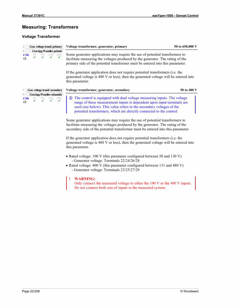
Gen. voltage transf. primary Voltage transformer, generator, primary 50 to 650,000 V
Some generator applications may require the use of potential transformers to facilitate measuring the voltages produced by the generator. The rating of the primary side of the potential transformer must be entered into this parameter. If the generator application does not require potential transformers (i.e. the generated voltage is 480 V or less), then the generated voltage will be entered into this parameter.
DE
Gen.Spg.Wandler primär CS0 12
0 1o 1oc 2oc
EN
Gen. voltage transf. secondary Voltage transformer, generator, secondary 50 to 480 V
The control is equipped with dual voltage measuring inputs. The voltage range of these measurement inputs is dependent upon input terminals are used (see below). This value refers to the secondary voltages of the potential transformers, which are directly connected to the control.
Some generator applications may require the use of potential transformers to facilitate measuring the voltages produced by the generator. The rating of the secondary side of the potential transformer must be entered into this parameter. If the generator application does not require potential transformers (i.e. the generated voltage is 480 V or less), then the generated voltage will be entered into this parameter. • Rated voltage: 100 V (this parameter configured between 50 and 130 V)
- Generator voltage: Terminals 22/24/26/28 • Rated voltage: 400 V (this parameter configured between 131 and 480 V)
- Generator voltage: Terminals 23/25/27/29
! WARNING: Only connect the measured voltage to either the 100 V or the 400 V inputs. Do not connect both sets of inputs to the measured system.
DE
Gen.Spg.Wandler sekundär CS0 13
0 1o 1oc 2oc

Manual 37391C easYgen-1000 - Genset Control
© Woodward Page 23/208
EN
Mains.volt. transf. primary Voltage transformer, mains, primary 50 to 650,000 V
Some applications may require the use of potential transformers to facilitate measuring the voltages to be monitored. The rating of the primary side of the potential transformer must be entered into this parameter. If the application does not require potential transformers (i.e. the measured voltage is 480 V or less), then the measured voltage will be entered into this parameter.
DE
Netz.Spg.Wandler primär CS0 14
0 1o 1oc 2oc --- --- ---
EN
Mains.volt. transf. secondary Voltage transformer, mains, secondary 50 to 480 V
The control is equipped with dual voltage measuring inputs. The voltage range of these measurement inputs is dependent upon input terminals are used (see below). This value refers to the secondary voltages of the potential transformers, which are directly connected to the control.
Some applications may require the use of potential transformers to facilitate measuring the mains voltages. The rating of the secondary side of the potential transformer must be entered into this parameter. If the application does not require potential transformers (i.e. the measured voltage is 480 V or less), then the measured voltage will be entered into this parameter. • Rated voltage: 100 V (this parameter configured between 50 and 130 V)
- Mains voltage: Terminals 14/16/18/20 • Rated voltage: 400 V (this parameter configured between 131 and 480 V)
- Mains Voltage: Terminals 15/17/19/21
! WARNING: Only connect the measured voltage to either the 100 V or the 400 V inputs. Do not connect both sets of inputs to the measured system.
DE
Netz.Spg.Wandler sekundär CS0 15
0 1o 1oc 2oc --- --- ---
Current Transformer
EN
Generator current transformer Current transformer, generator 1 to 32,000/x A
Current transformer ratio for the generator. The control can be optionally equipped with ../1 A or with ../5 A current transformer inputs. Depending on the version there are two different specifications of the parameter, which control the same memory location. You can find this value at the unit either on the data plate or via the software. The input of the current transformer ratio is necessary for the indication and control of the actual monitored value. The current transformers ratio should be selected so that at least 60% of the secondary current rating can be measured when the monitored system is at 100% of operating capacity (i.e. at 100% of system capacity a 5 A CT should output 3 A). If the current transformers are sized so that the percentage of the output is lower, the loss of resolution may cause inaccuracies in the monitoring and control functions and affect the functionality of the control. x = 1 .......... easYgen-1xxx-51B = Current transformer with ../1 A rated current, x = 5 .......... easYgen-1xxx-55B = Current transformer with ../5 A rated current.
DE
Generator Stromwandler CS0 16
0 1o 1oc 2oc

Manual 37391C easYgen-1000 - Genset Control
Page 24/208 © Woodward
EN
Input mains current Current transformer, input Mains / Ground / Off
Mains ........... Mains current input is used for measuring the mains current. The ground current is only provided as calculated ground current.
The ground current monitoring refers to the rated generator current!
Ground......... Mains current input is used for the directly measured ground
current. The calculated ground current is not evaluated anymore. The ground current monitoring refers to the rated transformer current
configured at the unit! Off ................ No measuring is performed at the mains current input and the
following mains values are not displayed: power factor, current, real power, and reactive power
DE
Eingang Netzstrom CS3 17
0 1o 1oc 2oc
NOTE It depends on the setting of the above parameter, whether one of the following screens is displayed.
EN
Mains curent transformer Current transformer, mains 1 to 32,000/x A
Current transformer ratio for the mains. The control can be optionally equipped with ../1 A or with ../5 A current transformer inputs. Depending on the version there are two different specifications of the parameter, which control the same memory location. You can find this value at the unit either on the data plate or via the software. The input of the current transformer ratio is necessary for the indication and control of the actual monitored value. The current transformers ratio should be selected so that at least 60% of the secondary current rating can be measured when the monitored system is at 100% of operating capacity (i.e. at 100% of system capacity a 5 A CT should output 3 A). If the current transformers are sized so that the percentage of the output is lower, the loss of resolution may cause inaccuracies in the monitoring and control functions and affect the functionality of the control. x = 1 ...........easYgen-1xxx-51B = Current transformer with ../1 A rated current, x = 5 ...........easYgen-1xxx-55B = Current transformer with ../5 A rated current.
DE
Netz Stromwandler CS0 18
0 1o 1oc 2oc --- --- ---
EN
Ground current transformer Current transformer, ground 1 to 32,000/x A
Ground current transformer ratio. The control can be optionally equipped with ../1 A or with ../5 A current transformer inputs. Depending on the version there are two different specifications of the parameter, which control the same memory location. You can find this value either on the data plate or via the software. The input of the current transformer ratio is necessary for the indication and control of the actual monitored value. The current transformers ratio should be selected so that at least 60% of the secondary current rating can be measured when the monitored system is at 100% of operating capacity (i.e. at 100% of system capacity a 5 A CT should output 3 A). If the current transformers are sized so that the percentage of the output is lower, the loss of resolution may cause inaccuracies in the monitoring and control functions and affect the functionality of the control. x = 1 ...........easYgen-1xxx-51B = Current transformer with ../1 A rated current, x = 5 ...........easYgen-1xxx-55B = Current transformer with ../5 A rated current.
DE
Erd-Stromwandler CS0 19
0 1o 1oc 2oc
Manual 37391C easYgen-1000 - Genset Control
© Woodward Page 25/208
Application ≡≡≡≡≡≡≡≡≡≡≡≡≡≡≡≡≡≡≡≡≡≡≡≡≡
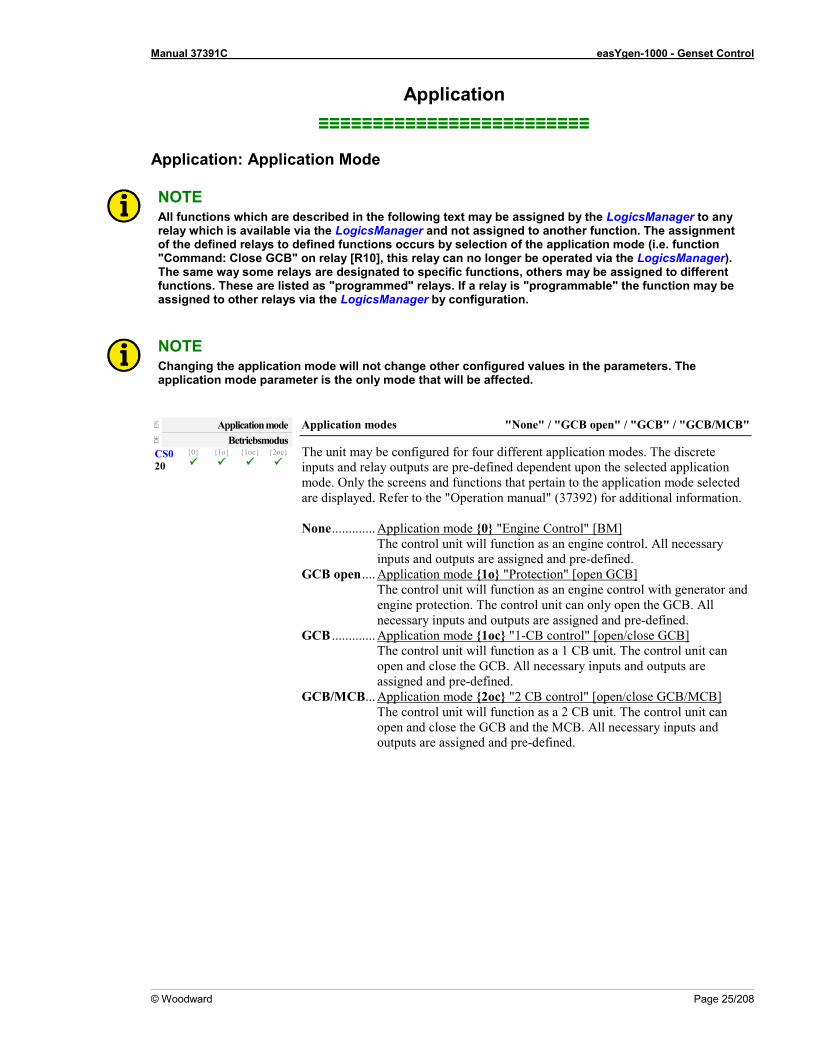
Application: Application Mode
NOTE All functions which are described in the following text may be assigned by the LogicsManager to any relay which is available via the LogicsManager and not assigned to another function. The assignment of the defined relays to defined functions occurs by selection of the application mode (i.e. function "Command: Close GCB" on relay [R10], this relay can no longer be operated via the LogicsManager). The same way some relays are designated to specific functions, others may be assigned to different functions. These are listed as "programmed" relays. If a relay is "programmable" the function may be assigned to other relays via the LogicsManager by configuration.
NOTE Changing the application mode will not change other configured values in the parameters. The application mode parameter is the only mode that will be affected.
EN
Application mode Application modes "None" / "GCB open" / "GCB" / "GCB/MCB"
The unit may be configured for four different application modes. The discrete inputs and relay outputs are pre-defined dependent upon the selected application mode. Only the screens and functions that pertain to the application mode selected are displayed. Refer to the "Operation manual" (37392) for additional information. None ............. Application mode 0 "Engine Control" [BM]
The control unit will function as an engine control. All necessary inputs and outputs are assigned and pre-defined.
GCB open .... Application mode 1o "Protection" [open GCB] The control unit will function as an engine control with generator and engine protection. The control unit can only open the GCB. All necessary inputs and outputs are assigned and pre-defined.
GCB ............. Application mode 1oc "1-CB control" [open/close GCB] The control unit will function as a 1 CB unit. The control unit can open and close the GCB. All necessary inputs and outputs are assigned and pre-defined.
GCB/MCB ... Application mode 2oc "2 CB control" [open/close GCB/MCB] The control unit will function as a 2 CB unit. The control unit can open and close the GCB and the MCB. All necessary inputs and outputs are assigned and pre-defined.
DE
Betriebsmodus CS0 20
0 1o 1oc 2oc

Manual 37391C easYgen-1000 - Genset Control
Page 26/208 © Woodward
Application: Start In AUTOMATIC Operating Mode (LogicsManager) The start of the engine can be performed via different logical conditions. This can be: • a discrete input, • a temperature level • an interface • a timer • any logical combination If this logical output becomes TRUE in AUTOMATIC operating mode, the generator starts and the GCB will be closed. The simultaneous activation of other LogicsManager outputs (e.g. Stop req. in Auto, Start w/o load) may affect this function. Only 1oc, 2oc: If this logical output becomes FALSE again, the GCB will be opened again and the generator will be stopped after the cool-down phase.
EN
Start req. in Auto Start request in operation mode AUTOMATIC LogicsManager
The LogicsManager and its default settings are explained on page 140 in Appendix B: "LogicsManager".
DE
Startanf. in Auto CS0 21
0 1o 1oc 2oc
Application: Stop In AUTOMATIC Operating Mode (LogicsManager) If this logical output becomes TRUE, it inhibits all other start processes (e.g. Start req. in Auto, emergency power, etc.). Stopping of the engine can be initiated externally via a discrete input or any logical combination.
EN
Stop req. in Auto Stop request in operation mode AUTOMATIC LogicsManager
The LogicsManager and its default settings are explained on page 140 in Appendix B: "LogicsManager".
DE
Stopanf. in Auto CS0 22
0 1o 1oc 2oc
Application: Operating Mode
EN
Start w/o load Start without assuming load LogicsManager
If this LogicsManager condition is TRUE switching from mains to generator supply following an engine start is prevented (the GCB operation is blocked). This function may be used to perform a test operation. If an emergency power case occurs meanwhile, it is still possible to change to generator operation. The LogicsManager and its default settings are explained on page 140 in Appendix B: "LogicsManager".
DE
Start ohne Übernahme CS0 23
0 1o 1oc 2oc --- ---
EN
Startup in mode Operating mode after applying the power supply Stop / Auto / Manual / last
If the controller is powered down, the unit will start in the following configured mode when it is powered up again. Stop ..............The unit starts in the STOP operating mode. Auto ..............The unit starts in the AUTOMATIC operating mode. Manual .........The unit starts in the MANUAL operating mode. last ................The unit starts in the last operating mode the control was in prior to
being de-energized.
DE
Einschalten in Betriebsart CS0 24
0 1o 1oc 2oc --- ---

Manual 37391C easYgen-1000 - Genset Control
© Woodward Page 27/208
NOTE For the selection of the operating mode via the LogicsManager (if two different operating modes have been selected simultaneously) the control unit will prioritize the modes as follows: 1. STOP, 2. MANUAL 3. AUTOMATIC
EN
Operation mode AUTO Activate operating mode AUTOMATIC LogicsManager
Once the conditions of the LogicsManager have been fulfilled the unit will change into operating mode AUTOMATIC. If AUTOMATIC mode is selected via the LogicsManager it is not possible to change operating modes via the front panel. The LogicsManager and its default settings are explained on page 140 in Appendix B: "LogicsManager".
DE
Betriebsart AUTO CS0 25
0 1o 1oc 2oc
EN
Operation mode MAN Activate operating mode MANUAL LogicsManager
Once the conditions of the LogicsManager have been fulfilled the unit will change into operating mode MANUAL. If MANUAL mode is selected via the LogicsManager it is not possible to change operating modes via the front panel. The LogicsManager and its default settings are explained on page 140 in Appendix B: "LogicsManager".
DE
Betriebsart MAN CS0 26
0 1o 1oc 2oc
EN
Operation mode STOP Activate operating mode STOP LogicsManager
Once the conditions of the LogicsManager have been fulfilled the unit will change into operating mode STOP. If STOP mode is selected via the LogicsManager it is not possible to change operating modes via the front panel. The LogicsManager and its default settings are explained on page 140 in Appendix B: "LogicsManager".
DE
Betriebsart STOP CS0 27
0 1o 1oc 2oc
NOTE If a stopping alarm (alarm class C, D, E, or F; refer to Alarm on page 138) occurs in AUTOMATIC operating mode, the alarm may only be acknowledged via external acknowledgement (refer to Protection: Alarm Acknowledgement on page 51) or after selecting STOP operating mode.
Application: Liquid Crystal Display (LC Display)
EN
Alternative screen Show alternative screens YES / NO
YES .............. The alternative screens are shown in the LC display. Refer to manual 37392.
NO ................ The standard screens are shown in the LC display. Refer to manual 37392.
DE
Alternative Anzeigemasken CS0 28
0 1o 1oc 2oc
EN
Show mains data Show mains data YES / NO
YES .............. The alternative screens are shown in the LC display. Refer to manual 37392.
NO ................ The standard screens are shown in the LC display. Refer to manual 37392.
DE
Netzdaten anzeigen CS0 29
0 1o 1oc 2oc --- --- ---

Manual 37391C easYgen-1000 - Genset Control
Page 28/208 © Woodward
Application: Dynamical Display The easYgen primary measurement display screen "Generator values - overview" provides five configurable display fields. The measurement value and the unit may be configured freely for each of these fields. The figure below shows these five fields with the default settings. The different fields have different value length restrictions. If a measurement value is assigned to a field with insufficient length, the value will not be displayed correctly. Field maximum length Field 1 31 px (pixels) Field 2 35 px (pixels) Field 3 28 px (pixels) Field 4 28 px (pixels) Field 5 35 px (pixels)
Figure 3-2: Dynamical display - fields
Two parameters are available for each field to configure the measurement value and unit to be displayed in the respective field.
EN
Value display field x Value display field x [x = 1 to 5] refer to selection below
This parameter configures the displayed measurement value for the respective display field. Consider the value length restrictions for the different fields. Off .................. No measurement value is displayed Gen. frq. ......... The generator frequency is displayed in [Hz] 31 px Gen. Pwr. ....... The generator power is displayed in [kW] 30 px Gen. PF .......... The generator power factor is displayed 27 px Gen Cur A ..... The generator current of phase L1 is displayed in [A] 25 px Gen Cur B...... The generator current of phase L2 is displayed in [A] 25 px Gen Cur C ..... The generator current of phase L3 is displayed in [A] 25 px GenCurAvg ... The average generator current of all three phases is
displayed in [A] 25 px Note: Refer to Appendix E: Average Generator Current Calculation on page 177 for detailed information about the calculation of the average generator current depending on the parameters "Generator voltage measuring" (Parameter 6) and "Generator current measuring" (Parameter 7). Batt. Vol ......... The battery voltage is displayed in [V] 24 px An. Inp.1 ........ The value of the analog input 1 is displayed 35 px An. Inp.2 ........ The value of the analog input 2 is displayed 35 px Eng. Spd. ........ The engine speed is displayed in [rpm] 28 px Note: The following J1939 engine status messages may be displayed if an ECU is connected and configured accordingly. If the J1939 values are not received correctly (due to a wire break or sensor defect), "----" is displayed in front of the engineering unit. ECUSPN100 .. The engine oil pressure is displayed in [bar] or [psi] 35 px ECUSPN110 .. The engine coolant temperature is displayed in [°C] or [°F] 28 px ECUSPN175 .. The engine oil temperature is displayed in [°C] or [°F] 28 px ECUSPN190 .. The engine speed is displayed in [rpm] 28 px
DE
Inhalt Anzeige Feld x CS3 30
0 1o 1oc 2oc

Manual 37391C easYgen-1000 - Genset Control
© Woodward Page 29/208
NOTE The J1939 values from the ECU have the following display range: • ECUSPN100 (engine oil pressure) 0 to 10.00 bar / 0 to 145 psi • ECUSPN110 (engine coolant temperature) -40 to 210 °C / -39 to 410 °F • ECUSPN175 (engine oil temperature) -273 to 1735 °C / -459 to 3155 °F • ECUSPN190 (engine speed) 0 to 8031 rpm
EN
Unit display field x Unit display field x [x = 1 to 5] refer to selection below
This parameter configures the unit, which is displayed next to the measurement value as a bitmap, for the respective display field. Off ................ No engineering unit is displayed following the measured value psi ................. "psi" is displayed following the measured value bar ................ "bar" is displayed following the measured value °C ................. "°C" is displayed following the measured value °F .................. "°F" is displayed following the measured value rpm .............. "rpm" is displayed following the measured value ohm .............. "ohm" is displayed following the measured value Note: Configuring a unit is only required if an analog input is selected in Parameter "Value display field x" and the analog input type (Parameter 247) is configured as "linear", "Table A", or "Table B". As an example, if the power, frequency or a J1939 value is configured to a display field, the measured values are automatically provided with the appropriate engineering unit. It is possible to add a display field unit bitmap to the displayed value. This may result in the engineering units overlapping and causing the display to appear corrupted or displaying an incorrect engineering unit.
DE
Einheit Anzeige Feld x CS3 31
0 1o 1oc 2oc
Display of the Units Depending on the Analog Input Type The display of the analog input values on the screen depends on the configured analog input type (Parameter 247). The following table indicates, which analog input types are already assigned an engineering unit:
Analog input type Screen display Off empty display VDO 5 bar "xx.xx" + "bar" or "psi" bitmap * VDO 10 bar "xx.xx" + "bar" or "psi" bitmap * VDO 150°C temp. value + "°C" or "°F" bitmap ** VDO 120°C temp. value + "°C" or "°F" bitmap ** Pt 100 temp. value + "°C" or "°F" bitmap ** SMP 2125 temp. value + "°C" or "°F" bitmap ** linear Depending on the formatting of the analog value. The formatting
may be configured with the parameter "Value format" (Parameter 253), which may only be accessed via LeoPC1.
Table A Depending on the formatting of the analog value. The formatting may be configured with the parameter "Value format" (Parameter 253), which may only be accessed via LeoPC1.
Table B Depending on the formatting of the analog value. The formatting may be configured with the parameter "Value format" (Parameter 253), which may only be accessed via LeoPC1.
* It depends on the setting of "Display pressure in" (Parameter 246) whether "bar" or "psi" is displayed here; the value is converted automatically
** It depends on the setting of "Display temperature in" (Parameter 245) whether "°C" or "°F" is displayed here; the value is converted automatically
Table 3-1: Dynamical display fields - units

Manual 37391C easYgen-1000 - Genset Control
Page 30/208 © Woodward
NOTE The freely configurable inputs do not require that the display format consist of numbers. It is also possible to mix text with digits. Example: A customer configures a format for an analog input in LeoPC1 as: "000lbs" The screen will display the measurement value followed by the text "lbs". The zeros are only used as placeholder for the measurement value.
Maximum Length of the Measurement Values The maximum length of the measurement values in the individual fields is: Field 1 = 5 digits Field 2 = 6 digits Field 3 = 5 digits Field 4 = 5 digits Field 5 = 6 digits Woodward recommends using fields 2 and 5 for analog input values because these fields display 6 digits permitting a higher resolution.

Manual 37391C easYgen-1000 - Genset Control
© Woodward Page 31/208
Application: Critical Mode (Sprinkler Operation, LogicsManager) The critical mode may be externally initiated via a discrete input. The LogicsManager is used to define the conditions that will enable the critical mode (for conditions and explanation of programming refer to LogicsManager on page 122).
Alarm Classes When critical mode is enabled the alarm classes are reclassified as follows: Alarm classes Normal operation A B C D E F Critical mode A B B B B B
Critical mode "ON" A critical mode will be initiated/started once the critical mode operation LogicsManager output becomes TRUE (logic "1"). The "Critical mode" message is displayed on the LC screen. If the engine is not already running, the controller will attempt to start the engine up to 10 times (unless configured for less). All shutdown alarms become warning messages (see above).
Critical mode "OFF" A critical mode will be interrupted/stopped once critical mode operation LogicsManager output becomes FALSE (logic "0"). The critical mode operation is continued for the configured critical mode postrun time. If the operation mode changes to STOP, this time will be considered as expired. With termination of the critical mode, a normal cool down is performed.
Critical mode and emergency power 2oc The emergency power operation has priority. If there is a mains failure during the critical mode, the generator will supply the busbar. The MCB will be opened and the GCB will be closed. The "Emerg/Critical" message is displayed on the LC screen and all shutdown alarms become warning alarms. Critical mode ends before mains recovery: The emergency power operation will be continued and all
shutdown alarms become active again. If the mains return, the unit transfers the load from generator supply to mains supply after the mains settling delay expires.
Emergency power operation ends before the end of the critical mode: The critical mode is maintained and the load is transferred from generator supply to mains supply after the mains settling delay expires. The engine remains running until the conditions for the critical mode are no longer existent.
Critical mode and start request The critical mode operation has priority. If there is a critical mode request while the generator is running, the GCB will be opened (in application mode 2oc there will be a change from generator supply to mains supply of the busbar). The "Critical mode" message is displayed on the LC screen and all shutdown alarms become warning alarms. Critical mode ends before the start request is terminated: The engine continues running (in application mode
2oc there will be a change from mains supply to generator supply of the busbar). All shutdown alarms will become active again. By resetting the start request the GCB will be opened and the engine will be stopped.
Start request will be terminated before the critical mode is terminated: The critical mode operation is continued. The engine keeps running until the conditions for the critical mode are no longer fulfilled.

Manual 37391C easYgen-1000 - Genset Control
Page 32/208 © Woodward
Parameters If this logical output becomes TRUE in AUTOMATIC operating mode, it starts the critical mode.
EN
Critical mode Critical mode request LogicsManager
The LogicsManager and its default settings are explained on page 140 in Appendix B: "LogicsManager".
DE
Sprinklerbetrieb 32
0 1o 1oc 2oc
EN
Critical mode postrun Critical mode postrun time 0 to 6000 s
The critical mode operation is continued for the time configured here after the critical mode request has been terminated.
DE
Sprinkler Nachlaufzeit 33
0 1o 1oc 2oc
EN
Close GCB in override Close GCB in critical mode YES / NO
YES ............. If a critical mode operation is detected the GCB will close. NO ............... The GCB cannot be closed during a critical mode operation.
DE
GLS schließen bei Sprinkler 34
0 1o 1oc 2oc --- ---
EN
Override alarm cl. also in MAN Critical mode alarm classes active in MANUAL operating mode YES / NO
YES ............. The critical mode alarm classes will override the normal operation alarm classes when in MANUAL operation mode if enable via the LogicsManager.
NO ............... The alarm classes will not be changed in the MANUAL operating mode.
DE
Sprinkler Alarmkl. in MAN 35
0 1o 1oc 2oc
EN
Break emergency in override Critical mode override emergency operations … 0 to 999 s
The emergency power operations are overridden for the configured time when the critical mode starts to supply the complete generator power to the sprinkler pump.
DE
Pause Notstrom bei Sprinkler 36
0 1o 1oc 2oc --- --- ---
Manual 37391C easYgen-1000 - Genset Control
© Woodward Page 33/208
Engine ≡≡≡≡≡≡≡≡≡≡≡≡≡≡≡≡≡≡≡≡≡≡≡≡≡
Engine: Start /Stop Sequence
NOTE All functions which are described in the following text, may be assigned by the LogicsManager to any relay that is available via the LogicsManager and not assigned another function. All
EN
Start/Stop mode Engine: Type of engine Diesel / Gas / External
Diesel or gas engine start/stop logic must be selected. The starting sequences are described in the following chapters. If this parameter is configured to "External" the start/stop sequence must be done externally.
DE
Start/Stop Modus 37
0 1o 1oc 2oc
Engine: Diesel Engine
Start sequence The relay "Pre-glow" will be energized for the preheating time period ("Preglow" display). Following preheating, the fuel solenoid is first energized and then the starter is engaged ("Start" display). When the configured firing speed is exceeded, the starter is disengaged and the fuel solenoid remains energized via the firing speed. If the engine fails to start, the starting sequence is blocked ("Stop engine" display) for a configurable time period ("Time for engine stop"), and the message "Crank protect" is displayed if starting of the engine is attempted. If the number of unsuccessful start attempts reaches the configured value, an alarm message will be issued ("Start fail" display).
Stop sequence After opening the GCB, the coasting time starts and the engine runs without load ("Cool down" display). On termination of the coasting time, the fuel solenoid is de-energized, and the engine is stopped ("Stop engine" display). If starting of the engine is attempted. If the engine cannot be stopped via the fuel solenoid, the alarm message "Shutdown malfct." appears.
Start/stop diagram The formula signs and indices mean: tHVL ............... Lead time auxiliary operation ....................[s] tVG ................. Preheating time ..........................................[s] tSV ................. Engagement time .......................................[s] tSP .................. Interval between 2 start attempts ...............[s] tMV ................ Engine delayed monitoring ........................[s] tHNL ............... Coasting time auxiliary operation ..............[s] tNL ................. Coasting time .............................................[s]

Manual 37391C easYgen-1000 - Genset Control
Page 34/208 © Woodward
Figure 3-3: Start /stop sequence - diesel engine
Star
t-Sto
p-P
roce
ss 2
005-
05-1
7.cd
r
t MV
t SP
t HNL
t SVt SV
t [s]
t [s]
t [s]
t [s]
t [s]
t [s]
t [s]
t VG
t [s]
t NL
t HVL
Dep
ends
on
para
met
ers
for "
Dea
d bu
s st
art"
0.5
s0.
5 s
Stop
ping
Star
ting
Star
t req
uest
Rat
ed s
peed
[RP
M]
Auxi
liary
ser
vice
s
Ope
ratin
g so
leno
id
Star
ter
Pre-
glowFi
ring
spee
d
Engi
nem
onito
ring
ON
[1/m
in; R
PM]
unsu
cces
sful
succ
essf
ul
Rep
ly:
GC
B is
clo
sed
An e
ngin
e po
st-r
un is
per
form
edfo
llow
ing
the
GC
B ha
s be
en c
lose
d.

Manual 37391C easYgen-1000 - Genset Control
© Woodward Page 35/208
Parameter
EN
Fuel relay: close to stop Diesel engine: Fuel relay for close to stop YES / NO
YES .............. Stop solenoid To stop the engine the stop solenoid is energized. The stop solenoid remains energized for and additional 30 s after speed is no longer detected from the engine.
NO ................ Operating solenoid Before each starting sequence the operating solenoid is energized. To stop the engine the operating solenoid is de-energized.
DE
Kraftstoffmagnet: Stopmag. 38
0 1o 1oc 2oc
EN
Preglow time Diesel engine: Preglow time [tVG] 0 to 300 s
Before each starting the diesel engine is preheated for this time (if a "0" has been configured here the engine will be started without preglow). The display indicates "Preglow".
DE
Vorglühzeit 39
0 1o 1oc 2oc
EN
Preglow mode Diesel engine: Preglow mode NO / Always / An.input [Tx]
This parameter dictates if and under what conditions a diesel engine is preheated. NO ................ The diesel engine is never preheated before a start attempt. Always ......... Before a start attempt the "Preheating" relay is always energized for
the pre-glow time (previous screen). After that a start attempt is initiated.
An.in.x ...... Preheating of the engine is initiated by a temperature transducer through the analog input [T1] = "Temp.1" or the analog input [T2] = "Temp.2". A requirement here is that the selected analog input is configured as a temperature measuring input. The limit of the temperature is set in the following screen.
DE
Vorglühmodus 40
0 1o 1oc 2oc
EN
Preglow temp. threshold Diesel engine: Preheating temperature set point value -10 to 60 °C
If the transducer temperature falls below the value entered here and the previous parameter ("temp 1" or "temp 2") is enabled and the diesel engine will be preheated.
DE
Vorglühen wenn T< 41
0 1o 1oc 2oc

Manual 37391C easYgen-1000 - Genset Control
Page 36/208 © Woodward
Engine: Gas Engine
Start sequence Function: The starter is engaged ("Turning" display). Following the expiration of the firing delay time and if the engine is rotating with at least the configured "minimum start speed", the ignition is switched on ("Ignition" display). Following the expiration of the gas valve delay, the gas valve is then enabled ("Start" display). If the starting attempt is successful (i.e. the configured firing speed is exceeded) the starter is disengaged. The gas valve and the ignition remain enabled via the firing speed. If the engine fails to start, the starting sequence is blocked for a configurable time period ("Time for engine stop"), and the message "Crank protect" is displayed if starting of the engine is attempted.
Stop sequence Function: After opening the GCB, the coasting time starts and the engine runs without load ("Cool down" display). On termination of the coasting time, the gas valve is closed or de-energized, and the engine is stopped ("Stop engine" display). If the engine cannot be stopped, the alarm message "Shutdown malfct." appears. If no speed is detected anymore, the ignition remains active for 5 seconds so that the remaining gas is able to combust.
CAUTION It is imperative to connect an emergency stop circuit to discrete input DI 1 to be able to perform an emergency stop by disabling the ignition in case the gas valve fails to close.
Start/stop diagram The formula signs and indices mean: tHVL ............... Lead time auxiliary operation......... [s] tSV ................. Starter time ..................................... [s] tSP ................. Start pause ...................................... [s] tZV................. Ignition delay ................................. [s] tGV ................ Gas delay ........................................ [s] tMV ................ Engine delayed monitoring ............ [s] tHNL ............... Coasting time auxiliary operation .. [s] tNL................. Coasting time ................................. [s] tZN................. Ignition coasting ("post burning") .. [s]
Parameter
EN
Ignition delay Gas engine: Ignition delay [tZV] 0 to 999 s
With gas engines often a purging operation is desired before starting. With the engaging of the starter the ignition delay is started. The display indicates "Turning". If the "Minimum speed for ignition" is reached after the expiration of this time, the ignition is energized.
DE
Zündverzögerung 42
0 1o 1oc 2oc
EN
Gas valve delay Gas engine: Gas valve delay [tGV] 0 to 999 s
By energizing the ignition relay the gas valve delay is started ("Ignition" display). After the time set here has expired, and as long as the speed is higher than the minimum speed for ignition, the gas valve is enabled for the time configured in Parameter 52 "Starter time" ("Start" display). Once the ignition speed has been reached, the gas valve remains opened. If the speed falls below ignition speed, the gas valve will be closed and the "Ignition" relay is de-energized 5 seconds later.
DE
Gasverzögerung 43
0 1o 1oc 2oc
EN
Min.speed for ignition Gas engine: Minimum speed for ignition 10 to 1.800 RPM
After expiration of the ignition delay the number of revolutions set here must be reached, so the "Ignition" relay will be energized.
DE
Mindestdrehz. für Zündung 44
0 1o 1oc 2oc

Manual 37391C easYgen-1000 - Genset Control
© Woodward Page 37/208
Figure 3-4: Start /stop sequence - gas engine - successful
t MV
t SP
t ZV
t GV
t NL
t ZNt HNL
t ZVt SV
t [s] t [s]
t [s]
t [s]
t [s]
t [s]
t [s]
Star
t-Sto
p-P
roce
ss 2
006-
02-2
2.cd
r
t [s]
Stop
ping
Star
ting
Min
imum
spe
edfo
r ign
ition
Star
t req
uest
Rat
ed s
peed
[RP
M]
Auxi
liary
ser
vice
s
Gas
val
ve
Igni
tion
Star
terFi
ring
spee
d
Engi
nem
onito
ring
ON
Min
imum
spe
ed fo
r ign
ition
will
not
be
reac
hed
[1/m
in; R
PM]
unsu
cces
sf.
succ
essf
ul
Rep
ly:
GC
B is
clo
sed
An e
ngin
e po
st-r
un is
per
form
edfo
llow
ing
the
GC
B ha
s be
en c
lose
d.D
epen
ds o
n pa
ram
eter
sfo
r "D
ead
bus
star
t"

Manual 37391C easYgen-1000 - Genset Control
Page 38/208 © Woodward
Figure 3-5: Start /stop sequence - gas engine - unsuccessful
t SP
t ZV
t GV
t ZVt SV
Star
t-Sto
p-Pr
oces
s 20
06-0
2-22
.cdr
t ZN
t SP
t HVL
Min
imum
spe
edfo
r ign
ition
Star
t req
uest
Rat
ed s
peed
[RP
M]
Auxi
liary
ser
vice
s
Gas
val
ve
Igni
tion
Star
terFi
ring
spee
d
Engi
nem
onito
ring
ON
Min
imum
spe
ed fo
r ign
ition
will
not
be
reac
hed
[1/m
in; R
PM
]
unsu
cces
sf.
unsu
cces
sful
Rep
ly:
GC
B is
clo
sed
Firin
g sp
eed
will
no
t be
reac
hed

Manual 37391C easYgen-1000 - Genset Control
© Woodward Page 39/208
Engine: Pickup To configure the pickup input, the following values must be configured: • Nominal speed (RPM) • The speed measurement method – via pickup (MPU) or an output at the alternator • Number of teeth on the flywheel detected by the magnetic pick up (MPU) or the number of pulses per
revolution of the engine.
EN
Speed Pickup Pickup ON / OFF
ON ................ Speed monitoring of the engine is carried out using an MPU or speed output.
OFF .............. Speed/frequency monitoring of the generator set (the engine) is performed by measuring the frequency of the generator. There is no MPU or sensor wired to this unit.
DE
Pickup 45
0 1o 1oc 2oc
EN
Nominal speed Nominal speed 500 to 4,000 RPM
Number of revolutions per minute of the engine at rated engine speed.
DE
Nenndrehzahl 46
0 1o 1oc 2oc
EN
Pickup measurement from: Pickup measurement from Pickup / Sensor
Pickup .......... Speed monitoring of the engine is carried out using an MPU. Sensor .......... Speed monitoring of the engine is carried out using the speed output
at the alternator (terminal W).
DE
Pickup Messung über: 47
0 1o 1oc 2oc
EN
Fly wheel teeth Number of flywheel teeth 2 to 260
This parameter is only visible, if Parameter 47 is configured to Pickup. The number of pulse per revolution/teeth on the flywheel is configured here.
DE
Anzahl Pickup-Zähne 48
0 1o 1oc 2oc
EN
Pulses per revolution Pulses per revolution 2.00 to 260.00
This parameter is only visible, if Parameter 47 is configured to Sensor. The number of pulse per revolution is configured here if a speed output at the alternator is used. Since the alternator is usually driven by a V-belt by the engine, the transmission ratio of the belt must be considered here. This parameter provides two decimal digits to be able to adjust any transmission ratio.
DE
Pulse pro Umdrehung 49
0 1o 1oc 2oc
EN
Filter time constant Filter time constant 0 to 8
The filter enables to filter heavily varying speed signals. This may be useful if the speed is measured using an output at the alternator (parameter 47 configured to "Sensor") because engine ignition timing and the elasticity of the V-belt may cause a heavily varying speed display. The speed display may be filtered with 8 stages. If "0" is configured here, no filter is applied. Note: If the filter is enabled, only the speed display is filtered. Speed monitoring and the speed value transmitted on the bus systems are not affected by the filter and use the measured speed data.
DE
Filter 50
0 1o 1oc 2oc

Manual 37391C easYgen-1000 - Genset Control
Page 40/208 © Woodward
Engine: Start/Stop Automatic
EN
Aux. services prerun Engine: Pre-run auxiliary operation (start preparation) [tHVL] 0 to 999 s
CAUTION: During an emergency start this delay time "auxiliary pre-run" is not initialized. The engine will be started immediately.
In the MANUAL operation mode the relay "auxiliary pre-run" is
permanently ON. Before each starting sequence this relay may be energized for an adjustable time (i.e. opening louvers). By energizing the relay output the message "Aux.serv.prerun" is displayed in the control screen. This relay is always energized if speed is detected. In the "MANUAL" operating mode this relay output is always energized. The signal remains ON until the operating mode is changed.
DE
Hilfsbetriebe Vorlauf 51
0 1o 1oc 2oc
EN
Starter time Engine: Maximum starter delay [tSV] 1 to 99 s
This is the maximum time that the starter relay will remain energized ("Start" display). If the discrete input for the LogicsManager function "Ignition speed reached" = TRUE, the speed/frequency have reached firing speed, or the time has expired the relay is then de-energized.
DE
Einrückzeit Anlasser 52
0 1o 1oc 2oc
EN
Start pause time Engine: Start pause time [tSP] 1 to 99 s
This is the delay time between the individual starting attempts. This time also is used to protect the starter relay. The message "Start - Pause" is displayed.
DE
Startpausenzeit 53
0 1o 1oc 2oc
EN
Cool down time Engine: Cool down time [tNL] 1 to 999 s
Regular stop: If the engine performs a normal stop (start request is disabled or change into STOP operating mode) or a stop caused by an alarm of alarm class C/D, a cool down with an opened GCB is carried out. This time is programmable. The message "Cool down" is displayed. Stop by a class 'C' or 'D' alarm: If the engine is stopped by an alarm of this alarm class, a cool down is carried out with an opened GCB. This time is programmable. Stop by a class 'E' or 'F' alarm: If the engine is stopped by an alarm of this alarm class, the engine is shutdown without a cool down immediately.
DE
Motor Nachlaufzeit 54
0 1o 1oc 2oc
EN
Auxiliary services postrun Engine: Coasting auxiliary operation (post operation) [tHNL] 0 to 999 s
After each engine stop (speed is no longer detected) this relay may remain energized for an adjustable time (i.e. operate a cooling pump). If the operating mode is changed from MANUAL to STOP or AUTOMATIC without a start command the relay remains energized for this period of time. The message "Aux. services" will be displayed on the control unit screen. In the "MANUAL" operating mode this relay output is always energized. The signal remains ON until the operating mode is changed.
DE
Hilfsbetriebe Nachlauf 55
0 1o 1oc 2oc
EN
Time of motor stop Engine: Engine blocking 0 to 99 s
During this time a restart of the engine is blocked. This time should be configured so that the engine is total shutdown to protect the starting circuit. Once speed from the engine is no longer detected the time configured in this parameter is initiated. ("Stop engine" display)
DE
Zeit für Motorstop 56
0 1o 1oc 2oc
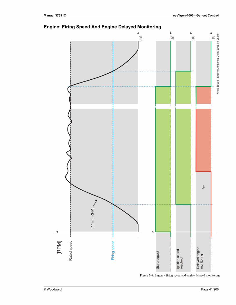
Manual 37391C easYgen-1000 - Genset Control
© Woodward Page 41/208
Engine: Firing Speed And Engine Delayed Monitoring
Figure 3-6: Engine - firing speed and engine delayed monitoring
Firin
g Sp
eed
- Eng
ine
Mon
itorin
g D
elay
200
5-04
-06.
cdr
t [s] t [s]
t [s]
t [s]
t MV
Del
ayed
eng
ine
mon
itorin
g
Star
t req
uest
Rat
ed s
peed
[RP
M]
Igni
tion
spee
dre
ache
dFirin
g sp
eed
[1/m
in; R
PM
]
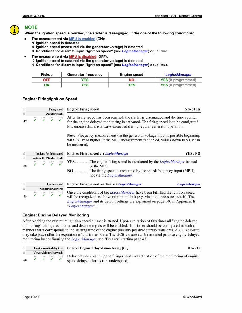
Manual 37391C easYgen-1000 - Genset Control
Page 42/208 © Woodward
NOTE When the ignition speed is reached, the starter is disengaged under one of the following conditions: • The measurement via MPU is enabled (ON):
Ignition speed is detected Ignition speed (measured via the generator voltage) is detected Conditions for discrete input "Ignition speed" (see LogicsManager) equal true.
• The measurement via MPU is disabled (OFF): Ignition speed (measured via the generator voltage) is detected Conditions for discrete input "Ignition speed" (see LogicsManager) equal true.
Pickup Generator frequency Engine speed LogicsManager
OFF YES NO YES (if programmed) ON YES YES YES (if programmed)
Engine: Firing/Ignition Speed
EN
Firing speed Engine: Firing speed 5 to 60 Hz
After firing speed has been reached, the starter is disengaged and the time counter for the engine delayed monitoring is activated. The firing speed is to be configured low enough that it is always exceeded during regular generator operation. Note: Frequency measurement via the generator voltage input is possible beginning with 15 Hz or higher. If the MPU measurement is enabled, values down to 5 Hz can be measured.
DE
Zünddrehzahl 57
0 1o 1oc 2oc
EN
Logicm. for firing speed Engine: Firing speed via LogicsManager YES / NO
YES ...............The engine firing speed is monitored by the LogicsManager instead of the MPU.
NO ................The firing speed is measured by the speed/frequency input (MPU), not via the LogicsManager.
DE
Logikm. für Zünddrehzahl 58
0 1o 1oc 2oc
EN
Ignition speed Engine: Firing speed reached via LogicsManager LogicsManager
Once the conditions of the LogicsManager have been fulfilled the ignition speed will be recognized as above minimum limit (e.g. via an oil pressure switch). The LogicsManager and its default settings are explained on page 140 in Appendix B: "LogicsManager".
DE
Zünddrehz. erreicht 59
0 1o 1oc 2oc
Engine: Engine Delayed Monitoring After reaching the minimum ignition speed a timer is started. Upon expiration of this timer all "engine delayed monitoring" configured alarms and discrete inputs will be enabled. This timer should be configured in such a manner that it corresponds to the starting time of the engine plus any possible startup transients. A GCB closure may take place after the expiration of this timer. Note: The GCB closure can be initiated prior to engine delayed monitoring by configuring the LogicsManager; see "Breaker" starting page 43).
EN
Engine monit. delay time Engine: Engine delayed monitoring [tMV] 0 to 99 s
Delay between reaching the firing speed and activation of the monitoring of engine speed delayed alarms (i.e. underspeed).
DE
Verzög. Motorüberwach. 60
0 1o 1oc 2oc

Manual 37391C easYgen-1000 - Genset Control
© Woodward Page 43/208
Engine: Idle Mode When the engine is operated at idle speed, undervoltage, underfrequency, and underspeed monitoring are not performed. The analog input monitoring uses the alternative limits, which may be configured for the idle mode (Parameter 260). The GCB cannot be closed in idle mode. This function allows for a controlled operation of an engine without alarm messages at a lower speed (lower than the configured monitoring values e.g. warm-up of an engine). Note: The idle mode is blocked when the GCB is closed. A message may be output to a relay here using the LogicsManager (Idle mode is active, command variable 4.15), e.g. as a signal for s speed controller. The display indicates "Idle run active" during idle mode.
EN
Constant idle run Engine: LogicsManager continuous idle mode LogicsManager
Once the conditions of the LogicsManager have been fulfilled the engine will be continuously operated in idle mode. Undervoltage, underfrequency, and underspeed monitoring are not performed. A key switch via a DI may be configured here for example. The LogicsManager and its default settings are explained on page 140 in Appendix B: "LogicsManager".
DE
Dauernd Idle Modus 61
0 1o 1oc 2oc
EN
Idle mode automatic Engine: LogicsManager automatic idle mode LogicsManager
Once the conditions of the LogicsManager have been fulfilled the engine will be operated in idle mode automatically for the configured time during start-up. Undervoltage, underfrequency, and underspeed monitoring are not performed. This function may always be configured to "1" for example. The LogicsManager and its default settings are explained on page 140 in Appendix B: "LogicsManager".
DE
Automatic Idle Modus 62
0 1o 1oc 2oc
EN
Time for automatic idle run Engine: Time for automatic idle mode 1 to 9999 s
The automatic idle mode is active for the time configured here. Undervoltage, underfrequency, and underspeed monitoring are not performed during this time.
DE
Zeit für Automatic Idle Modus 63
0 1o 1oc 2oc
EN
During emerg/critical Engine: Idle mode possible during AMF / critical operation YES / NON
YES ..............If an AMF or sprinkler operation is enabled, the engine will go to rated speed only after completing the configured idle mode.
NO ................If an AMF or critical operation is enabled, the idle mode will be overridden and the engine will go directly to rated speed.
DE
Während Notstrom/Sprinkler 64
0 1o 1oc 2oc
NOTE The idle mode will be deactivated and normal operation monitoring limits (Parameter 259) will be enabled again, if one of the following conditions is fulfilled: • Generator frequency and voltage are within the dead bus start limits (Parameter 70 and 71). • Engine delayed monitoring (Parameter 60) has expired after the idle mode has ended.
NOTE The analog inputs alternate limit of the analog inputs for the idle mode is configured with Parameter 260.

Manual 37391C easYgen-1000 - Genset Control
Page 44/208 © Woodward
Breaker ≡≡≡≡≡≡≡≡≡≡≡≡≡≡≡≡≡≡≡≡≡≡≡≡≡
Breaker: Operation Of The Circuit Breakers Switching the pulses takes place in the following screen and has the described effect on the signal sequence (the MCB cannot be controlled by the continuous pulse for security reasons, because otherwise, the MCB would be opened in case of a failure/exchange of the easYgen). If the parameter "Auto unlock" is configured to YES, an open pulse will be issued prior to each close pulse. The parameter "Enable MCB" prevents the closing of the MCB. A closed MCB will not be opened.
Dead bus start GCB 1oc or 2oc The GCB is closed, if the following conditions are met simultaneously. The display indicates "GCB dead bus cls". Automatic operation
• The operating mode AUTOMATIC has been selected • No class C alarm or higher is present • The engine is running • The engine delayed monitoring (Parameter 60) as well as the GCB breaker delay (Parameter 72) have
been expired or the LogicsManager function "Undelayed close of GCB" (Parameter 69) is enabled • The generator voltage and frequency are within the configured limits (Parameters 70 and 71) • The MCB has been opened for at least the time configured in "Transfer time GCB↔MCB" (Parameter 77)
(2oc only) • The function "Start without load" (Parameter 23) has been disabled through the LogicsManager • Only in critical mode: the parameter "Close GCB in override" (Parameter 34) is configured to YES
Manual operation
• The operating mode MANUAL has been selected. • No class C alarm or higher is present • The engine is running • The engine delayed monitoring (Parameter 60) as well as the GCB breaker delay (Parameter 72) have
been expired • The generator voltage and frequency are within the configured limits (Parameters 70 and 71) • The MCB has been open for at least the time configured in "Transfer time GCB↔MCB" (Parameter 77)
(2oc only) • The button "Close GCB" has been pressed
Manual 37391C easYgen-1000 - Genset Control
© Woodward Page 45/208
Dead bus start MCB 2oc The MCB is closed, if the following conditions are met simultaneously. The display indicates "MCB dead bus cls". Automatic operation
• The operating mode AUTOMATIC has been selected • The mains voltage is available and within the configured limits (Parameters 70 and 71) • The GCB is open or has been opened for at least the "Transfer time GCBMCB" (Parameter 77) • "Enable MCB" (Parameter 76) is configured as ALWAYS or discrete input 6 is energized if configured as
DI 6 Manual operation
• Operating mode MANUAL has been selected • The mains voltage is available and within the configured limits (Parameters 70 and 71) • The GCB is open or has been opened for at least the "Transfer time GCBMCB" (Parameter 77) • "Enable MCB" (Parameter 76) is configured as ALWAYS or discrete input 6 is energized if configured as
DI 6 • The button "Close MCB" has been pressed
Open GCB 1o or 1oc or 2oc The GCB is opened when the relay "Command: GCB close" de-energizes (only if Parameter 67 "GCB close pulse" is configured as NO) and when the relay "Command GCB open" energizes. The GCB will be opened under the following circumstances.
• In STOP operating mode • In case of a class C alarm or higher • By pressing the button "GCB open" or "MCB close" (depending on the CB logic which has been set) in
MANUAL operating mode • By pressing the button "stop engine" in MANUAL operating mode • In the event of an automatic stopping in the AUTOMATIC operating mode (the start request has been
terminated or a stop request has been initiated) • Prior to the MCB closing onto the dead busbar • In critical mode (Sprinkler operation), provided that an emergency power operation is not active, and
"Close GCB in override" (Parameter 34) has been configured to NO • If "Start without load" has been enabled through the LogicsManager
Open MCB 2oc The MCB is opened when the relay "Command: MCB open" is energized. The MCB will be opened under the following circumstances.
• If an emergency power operation is initiated (mains failure) once the generator voltage is within the permissible limits
• Prior to the closure of the GCB • Upon pressing the "MCB OPEN" or "GCB CLOSE" push-button (dependent upon the configured CB
logic) in MANUAL operating mode

Manual 37391C easYgen-1000 - Genset Control
Page 46/208 © Woodward
Breaker: GCB Settings
NOTE Operating current (NO): The relay is enabled (i.e. in the operating state) when current flows through the
coil. If a loss of the supply voltage occurs, the relay contacts will not transfer and a fault condition will not be monitored. In this mode of operation the state of the system should be monitored through other means than the state of the relay.
Closed circuit current (NC): The relay is disabled (i.e. in idle state) when current flows through the coil. The relay is energized in idle state. If a loss of the supply voltage occurs, the relay contacts will transfer and a fault condition will be monitored.
Figure 3-7: Operating / closed circuit current
EN
GCB open relay Breaker: "Command: GCB open" relay N.O. / N.C.
N.O. (normally open) If the GCB is to be opened, the relay "command: GCB open" is energized. When the control receives the message "Reply GCB is open", the relay is de-energized.
N.C. (normally closed) If the GCB is to be opened, the relay "command: GCB open" de-energizes. When the control receives the message "Reply: GCB is open", the relay is energized again.
DE
GLS Öffnen-Kontakt 65
0 1o 1oc 2oc ---
EN
GCB time pulse Breaker: Pulse duration to close the GCB 0.04 to 10.00 s
The time of the pulse output may be adjusted to the breaker being utilized.
DE
GLS Impulsdauer 66
0 1o 1oc 2oc ---
EN
GCB close pulse Breaker: "Command: GCB close" issue as pulse YES / NO
YES ..............Configured momentary output: The relay "Command: GCB close" issues an add-on pulse. If the relay is configured in this manner a holding coil and sealing contacts must be installed externally to the control unit. The DI "Reply: GCB closed" is used to identify closed contacts.
NO ................Configured maintaining output: The relay "Command: close GCB" may be wired directly into the holding circuit for the power circuit breaker. If this method is utilized it is recommended that isolation relays be used. After the connect pulse has been issued and the reply of the power circuit breaker has been received, the relay "Command: close GCB" remains energized. If a class C alarm or higher occurs or the GCB is opened, this relay de-energizes.
In both cases the relay "Command: GCB open" energizes to open the GCB.
DE
GLS Schließen Impuls 67
0 1o 1oc 2oc --- ---
Relay programmed as 'operating current relay'Operating currentcontact
Idle-currentcontact
curre
nt fl
ow
0 V
RELEASERelay operates
24 V
RELEASEOperating currentcontact
Idle-currentcontact
RELEASERelay releases
no c
urre
nt fl
ow0 V
Relay programmed as 'idle-current relay'
RELEASE
24 V

Manual 37391C easYgen-1000 - Genset Control
© Woodward Page 47/208
EN
GCB auto unlock Breaker: Breaker unblocking GCB YES / NO
This is used for special circuit breakers to put the breaker into a defined initial state or to enable closing at all. YES .............. Before every close-pulse, an open-pulse is issued for 1 second. A CB
close pulse is enabled only after the open pulse is issued. NO ................ The CB close pulse is enabled without being preceded by a CB open
pulse.
DE
GLS auto entriegeln 68
0 1o 1oc 2oc --- ---
EN
Undelayed close GCB Breaker: Undelayed closing of the GCB LogicsManager
Once the conditions of the LogicsManager have been fulfilled the GCB will be closed immediately (without waiting for the delayed by engine speed timer to expire). When using the standard setting, the GCB will be closed without delay in AMF operation. The LogicsManager and its default settings are explained on page 140 in Appendix B: "LogicsManager".
DE
GLS unverzögert 69
0 1o 1oc 2oc --- ---
EN
GCB frequency window Breaker: "Command: GCB close": maximum frequency deviation 0.2 to 10.0 %
This value refers to the Rated system frequency (Parameter 3, see page 19). This is the maximum amount that the frequency will be allowed to deviate from the rated frequency and the "Command: GCB close" may be issued. This is to prevent the prime mover from going into an underfrequency condition due to overloading.
DE
GLS Frequenzabweichung 70
0 1o 1oc 2oc --- ---
EN
GCB voltage window Breaker: "Command: GCB close": maximum voltage deviation 1 to 100 %
This value refers to the Rated generator voltage (Parameter 4, see page 19). This is the maximum amount that the voltage will be allowed to deviate from the rated voltage and the "Command: GCB close" may be issued.
DE
GLS Spannungsabweichung 71
0 1o 1oc 2oc --- ---
EN
Gen. settling time Breaker: "Command: GCB close": Breaker delay 0 to 99 s
The time configured here begins to count down once the engine monitoring delay timer has expired. This permits for an additional delay time before the breaker is closed in order to ensure that none of the engine delayed watchdogs trips. It is possible to bypass this delay time through the LogicsManager (see Parameter 69) in the event an emergency operation condition (mains failure) occurs. Background: This additional delay time, which starts upon expiration of the "delayed engine monitoring" is used to prevent unnecessary interruptions of the voltage supply of the consumers. This condition occurs during switching operations from the mains to the generator. Every time a switching operation occurs the bus is without voltage for a short time. The consumers can be supplied once the "GCB settling time" has been expired. If the GCB would be closed prior to expiration of the delayed engine monitoring (by enabling this via the LogicsManager) and an alarm would become active after expiration of the delayed engine monitoring, the GCB would have to be opened and the consumers would be without voltage again. Unnecessary CB switching operations and voltage interruptions should be avoided by utilizing this parameter.
DE
GLS Schalterverzögerung 72
0 1o 1oc 2oc --- ---

Manual 37391C easYgen-1000 - Genset Control
Page 48/208 © Woodward
Breaker: MCB Settings 2oc
EN
MCB auto unlock Breaker: Switch unblocking MCB YES / NO
This is used for special circuit breakers to put the breaker into a defined initial state or to enable closing at all. YES ..............Before every close-pulse, an open-pulse is issued for 1 second. A CB
close pulse is enabled only after the open pulse is issued. NO ................The CB close pulse is enabled without being preceded by a CB open
pulse.
DE
NLS auto entriegeln 73
0 1o 1oc 2oc --- --- ---
EN
Close MCB in stop mode Breaker: Close MCB in STOP mode YES / NO
YES ..............The MCB may be closed in the STOP operation mode as long as the closing conditions are fulfilled.
NO ................The MCB cannot be closed in the STOP operation mode.
DE
NLS schließen im Stopmodus 74
0 1o 1oc 2oc --- --- ---
EN
MCB time impulse Breaker: Impulse duration to close the MCB 0.04 to 10.00 s
The time of the pulse output may be adjusted to the breaker being utilized.
DE
NLS Impulsdauer 75
0 1o 1oc 2oc ---
EN
Enable MCB Breaker: Enable MCB ALWAYS / DI6
ALWAYS .....The MCB is always enabled and the discrete input 6 may be configured freely.
DI6 ................Enabling the MCB is performed by energizing discrete input 6 (Enable MCB).
DE
Freigabe NLS 76
0 1o 1oc 2oc --- --- ---
Breaker: GCB/MCB Settings 2oc
EN
Transfer time GCB↔MCB Breaker: Transfer time GCB ↔ MCB 0.10 to 99.99 s
Switching from generator supply to mains supply or from mains supply to generator supply occurs automatically if the operating conditions have been met. The time between the reply "power circuit breaker is open" and a close pulse is set by this parameter. This time applies for both directions. During this time the consumers are de-energized.
DE
Pausenzeit GLS↔NLS 77
0 1o 1oc 2oc --- --- ---

Manual 37391C easYgen-1000 - Genset Control
© Woodward Page 49/208
Emergency Power (AMF) ≡≡≡≡≡≡≡≡≡≡≡≡≡≡≡≡≡≡≡≡≡≡≡≡≡
NOTE The emergency power operation is possible only in application mode 2oc (2 power circuit breakers). If the function 'Stop in AUTO' or 'inhibit emergency power' has been assigned to a discrete input, an emergency power operation may be prevented or interrupted from an external source.
Prerequisite: The emergency power function can only be activated in the case of synchronous generators by the configuration screen "Emergency power ON". Emergency power is carried out in operating mode AUTOMATIC regardless of the status of the discrete input 'Start in AUTO' (LogicsManager). The display indicates "Emergency run" during emergency power operation. Activation of emergency power: If a mains power fault is detected on at least one or more of terminals 14-21 for the duration of the time set in the "Emergency power delay time ON" screen, an emergency power operation is activated. A mains voltage fault is defined using the following limits: Permissible predetermined limits Mains Voltage Parameter values (refer to "Protection/Mains failure detection "; page 82) Frequency Parameter values (refer to "Protection/Mains failure detection"; page 82) Rotation Parameter values (refer to "Protection/Mains phase rotation"; page 81)
Table 3-2:Permissible limits
The following principles are observed in the case of emergency power: • If an emergency power operation is initiated, the engine is started under all circumstances, unless the start
sequence is interrupted via an alarm or prevented via the LogicsManager or the operating mode is changed. • The GCB can be closed regardless of the engine delay time after the dead bus starting limits have been
reached if the parameter 69 has be set accordingly. • If the mains return during an emergency power operation (GCB is closed), the mains settling time must expire
before the load is transferred from the generator to mains operation. MCB malfunction: The following is the protocol the unit follows when the control unit is in the AUTOMATIC operating mode, there has not been a start request, and the control unit is configured as emergency power standby. If the MCB opens, the control system attempts to reclose the breaker. If this is not possible (due to an MCB alarm), the engine is started due to the "MCB malfunction" if the parameter "Emergency power" is configured to "ON". Emergency power subsequently supplies the busbar. Only following the successful acknowledgment of the "MCB malfunction" alarm, is the GCB opened and the MCB closed and the engine shuts off again. Emergency power is also triggered via the detection of a switch fault when the MCB is switched on regularly. In order to achieve this, the "Emergency start with MCB failure" (Parameter 81) and "MCB monitoring" (Parameter 172) must be configured as "ON" . Mains rotation field alarm: If the mains returns after a mains failure with a reversed rotation direction the generator remains in emergency power operation until the mains rotation matches the rotation of the generator set.

Manual 37391C easYgen-1000 - Genset Control
Page 50/208 © Woodward
EN
On/Off Emergency power: Monitoring ON / OFF
ON ............... If the unit is in the AUTOMATIC operating mode and a mains fault occurs according to the following parameters, the engine is started and an automatic emergency operation is carried out.
OFF ............. No emergency operation is carried out.
DE
Ein/Aus 78
0 1o 1oc 2oc --- --- ---
EN
Mains fail delay time Emergency power: Mains failure: Start delay 0.20 to 99.99 s
To start the engine and to carry out an emergency operation the monitored mains must be failed continuously for the minimum period of time set with this parameter. This delay time starts only if the easYgen is in AUTOMATIC operating mode and emergency power is activated.
DE
Startverzögerung 79
0 1o 1oc 2oc --- --- ---
EN
Mains settling time Emergency power: Mains failure: Mains settling time 0 to 9,999 s
To end the emergency operation, the monitored mains must be within the configured operating parameters without interruption for the minimum period of time set with this parameter without interruption. This parameter permits delaying the switching of the load from the generator to the mains. The display indicates "Mains settling" during this time.
DE
Netzberuhigungszeit 80
0 1o 1oc 2oc --- --- ---
NOTE The reduced mains settling time is always active in MANUAL operating mode regardless of the breaker feedback and the setting of parameter 78 (Emergency power). The reduced mains settling time is fixed to 2 seconds. The reduced mains settling time is always active in STOP operating mode. The reduced mains settling time is fixed to 2 seconds.
EN
Emerg. start with MCB failure Emergency power: Emergency operation by MCB failure YES / NO
Emergency power operations may be configured with the failure of the MCB in addition to a loss of power on the main supply. An MCB breaker alarm is indicated if Parameter 172 "Monitoring MCB" is configured "ON".
DE
Bei NLS-Fehler aktivieren 81
0 1o 1oc 2oc --- --- ---
EN
Inhibit Emergency run Emergency power: Inhibit emergency power LogicsManager
Once the conditions of the LogicsManager have been fulfilled the emergency power operation will be terminated or blocked. The LogicsManager and its default settings are explained on page 140 in Appendix B: "LogicsManager".
DE
Kein Notstrombetrieb 82
0 1o 1oc 2oc --- --- ---

Manual 37391C easYgen-1000 - Genset Control
© Woodward Page 51/208
Protection ≡≡≡≡≡≡≡≡≡≡≡≡≡≡≡≡≡≡≡≡≡≡≡≡≡
Protection: Alarm Acknowledgement
EN
Time until horn reset Self acknowledgment of the centralized alarm (horn) 0 to 1,000 s
Alarm class A - Alarm class A messages are acknowledged using the "" button on the front panel. Alarm class B to F - After each alarm of this alarm class occurs, the alarm LED flashes and the command variable 03.05 (horn) is issued. After the delay time 'time until horn reset' has expired, the flashing LED changes into a steady light and the command variable 03.05 (horn) is reset. The alarm LED flashes until the alarm has been acknowledged either via the push button, the LogicsManager, or the interface. Note: If this parameter is configured to 0, the horn will remain active until it will be acknowledged.
DE
Zeit Hupenreset 83
0 1o 1oc 2oc
EN
External acknowledge Protection: External acknowledgment of alarms LogicsManager
It is possible to acknowledge all alarms simultaneously from remote, e.g. with a discrete input. The command variables of the LogicsManager have to become TRUE twice. The first time is for acknowledging the horn, the second for all alarm messages. The On-delay time is the minimum time the input signals have to be "1". The OFF-delay time is the time how long the input conditions have to be "0" before the next high signal is accepted. Once the conditions of the LogicsManager have been fulfilled the alarms will be acknowledged. The first high signal into the discrete input acknowledges the command
variable 03.05 (horn). The second high signal acknowledges all inactive alarm messages.
The LogicsManager and its default settings are explained on page 140 in Appendix B: "LogicsManager".
DE
Ext. Quittierung 84
0 1o 1oc 2oc
Protection: Generator Protection
EN
Voltage monitoring generator Generator protection: Type of monitoring 3 phase / 4 phase
The unit can either monitor the wye voltages (phase-neutral: 3ph-4w, 1ph-3w and 1ph-2w) or the delta voltages (phase-phase: 3ph-3w and 3ph-4w). Usually, for the low-voltage system the phase voltages are monitored, while for the medium to high voltage systems the delta voltages are monitored. The monitoring of the wye voltage is above all necessary to avoid earth-faults in a compensated or isolated network resulting in the tripping of the voltage protection. WARNING:
This parameter influences the protective functions. 3 phase ......... The phase-phase voltage will be measured and all subsequent
parameters concerning voltage monitoring "generator" are referred to this value (VL-L).
4 phase ......... The phase-neutral voltage will be measured and all subsequent parameters concerning voltage monitoring "generator" are referred to this value (VL-N).
DE
Spg.Überwachung Generator 85
0 1o 1oc 2oc ---
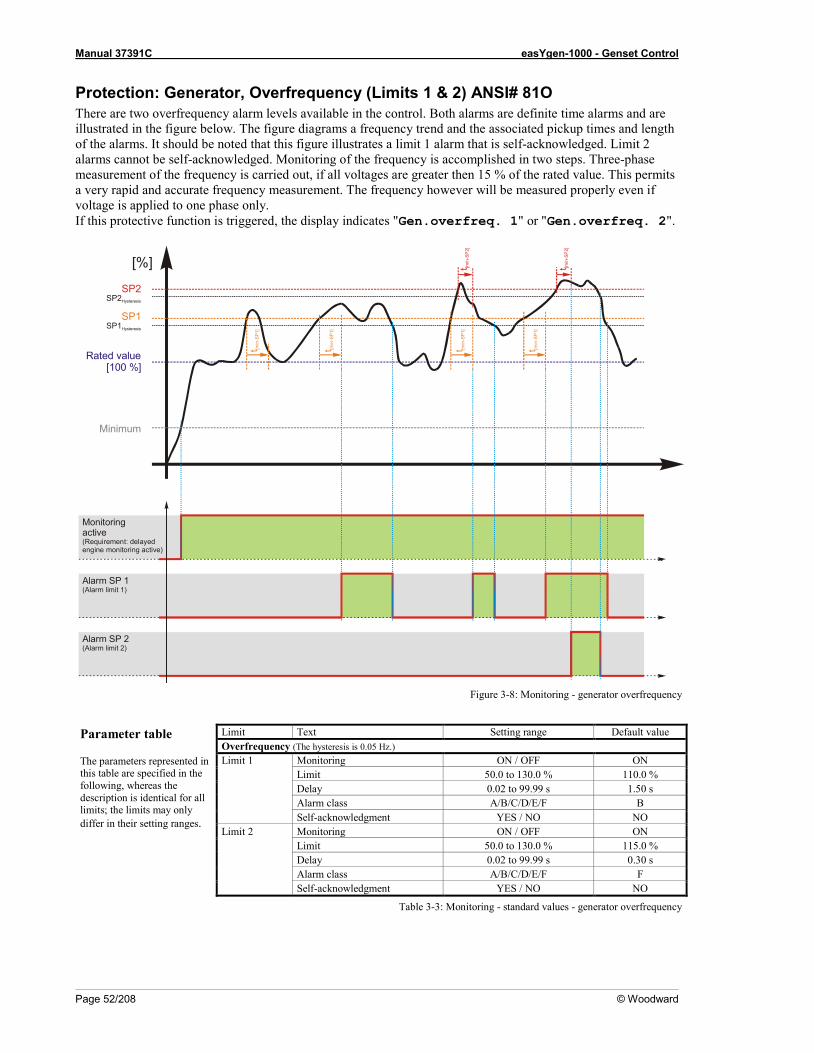
Manual 37391C easYgen-1000 - Genset Control
Page 52/208 © Woodward
Protection: Generator, Overfrequency (Limits 1 & 2) ANSI# 81O There are two overfrequency alarm levels available in the control. Both alarms are definite time alarms and are illustrated in the figure below. The figure diagrams a frequency trend and the associated pickup times and length of the alarms. It should be noted that this figure illustrates a limit 1 alarm that is self-acknowledged. Limit 2 alarms cannot be self-acknowledged. Monitoring of the frequency is accomplished in two steps. Three-phase measurement of the frequency is carried out, if all voltages are greater then 15 % of the rated value. This permits a very rapid and accurate frequency measurement. The frequency however will be measured properly even if voltage is applied to one phase only. If this protective function is triggered, the display indicates "Gen.overfreq. 1" or "Gen.overfreq. 2".
Figure 3-8: Monitoring - generator overfrequency
Parameter table The parameters represented in this table are specified in the following, whereas the description is identical for all limits; the limits may only differ in their setting ranges.
Limit Text Setting range Default value Overfrequency (The hysteresis is 0.05 Hz.) Limit 1 Monitoring ON / OFF ON Limit 50.0 to 130.0 % 110.0 % Delay 0.02 to 99.99 s 1.50 s Alarm class A/B/C/D/E/F B Self-acknowledgment YES / NO NO Limit 2 Monitoring ON / OFF ON Limit 50.0 to 130.0 % 115.0 % Delay 0.02 to 99.99 s 0.30 s Alarm class A/B/C/D/E/F F Self-acknowledgment YES / NO NO
Table 3-3: Monitoring - standard values - generator overfrequency
[%]
Monitoringactive(Requirement: delayedengine monitoring active)
Minimum
SP2Hysteresis
SP1Hysteresis
Rated value[100 %]
Alarm SP 1(Alarm limit 1)
Alarm SP 2(Alarm limit 2)
t [min
-SP
1]
t [min
-SP
1]
t [min
-SP
1]
t [min
-SP
1]
t [min
-SP
2]
t [min
-SP
2]
SP1
SP2
Manual 37391C easYgen-1000 - Genset Control
© Woodward Page 53/208
EN
Monitoring Gen.Overfrequency: Monitoring (limit 1/limit 2) ON / OFF
ON ................ Overfrequency monitoring is carried out according to the following parameters. Monitoring is performed at two levels. Both values may be configured independent from each other (prerequisite: limit 1 < limit 2).
OFF .............. Monitoring is disabled for limit 1 and/or limit 2. DE
Überwachung 86
0 1o 1oc 2oc ---
EN
Limit Gen.Overfrequency: Threshold value (limit 1/limit 2) 50.0 to 130.0 %
This value refers to the Rated system frequency (Parameter 3, see page 19). The percentage values that are to be monitored for each threshold limit are defined here. If this value is reached or exceeded for at least the delay time without interruption, the action specified by the alarm class is initiated.
DE
Limit 87
0 1o 1oc 2oc ---
EN
Delay Gen.Overfrequency: Delay (limit 1/limit 2) 0.02 to 99.99 s
If the monitored generator frequency value exceeds the threshold value for the delay time configured here, an alarm will be issued. If the monitored generator frequency falls below the threshold (minus the hysteresis) before the delay expires the time will be reset.
DE
Verzögerung 88
0 1o 1oc 2oc ---
EN
Alarm class Gen.Overfrequency: Alarm class (limit 1/limit 2) Class A/B/C/D/E/F
See chapter "Alarm" on page 138. The alarm class assigned to each limit alarm.
DE
Alarmklasse 89
0 1o 1oc 2oc ---
EN
Self acknowledge Gen. overfrequency: Self acknowledgment (limit 1/limit 2) YES / NO
YES .............. The control automatically clears the alarm if it is no longer valid. NO ................ An automatic reset of the alarm does not occur. The reset occurs
manually by pressing the appropriate buttons, by activating the LogicsManager output "External acknowledgement" via an discrete input, or via an interface.
DE
Selbstquittierend 90
0 1o 1oc 2oc ---

Manual 37391C easYgen-1000 - Genset Control
Page 54/208 © Woodward
Protection: Generator, Underfrequency (Limits 1 & 2) ANSI# 81U There are two underfrequency alarm levels available in the control. Both alarms are definite time alarms and are illustrated in the figure below. The figure diagrams a frequency trend and the associated pickup times and length of the alarms. It should be noted that this figure illustrates a limit 1 alarm that is self-acknowledged. Limit 2 alarms cannot be self-acknowledged. Monitoring of the frequency is performed in two steps. Measuring of the frequency occurs three-phase, if all voltages are larger than 15 % of the rated frequency. This permits quick and exact frequency measuring. The frequency however will be measured correctly even if voltage is applied only to one phase. If this protective function is triggered, the display indicates "Gen.underfreq. 1" or "Gen.underfreq. 2".
Figure 3-9: Monitoring - generator underfrequency
Parameter table The parameters represented in this table are specified in the following, whereas the description is identical for all limits; the limits may only differ in their setting ranges.
Limit Text Setting range Standard value Underfrequency (The hysteresis is 0.05 Hz.) Limit 1 Monitoring ON / OFF ON Limit 50.0 to 130.0 % 90.0 % Delay 0.02 to 99.99 s 5.00 s Alarm class A/B/C/D/E/F B Self-acknowledgment YES / NO NO Delayed by engine speed YES / NO NO Limit 2 Monitoring ON / OFF ON Limit 50.0 to 130.0 % 84.0 % Delay 0.02 to 99.99 s 0.30 s Alarm class A/B/C/D/E/F F Self-acknowledgment YES / NO NO Delayed by engine speed YES / NO NO
Table 3-4: Monitoring - Standard values - generator underfrequency
[%]
Monitoringactive(Requirement: delayedengine monitoring active)
Minimum
SP2Hysteresis
SP1Hysteresis
Rated value[100 %]
Alarm SP 1(Alarm limit 1)
Alarm SP 2(Alarm limit 2)
t [min
-SP1
]
t [min
-SP1
]
t [min
-SP
2]
SP1
SP2
t [min
-SP1
]
t [min
-SP1
]
t [min
-SP
2]

Manual 37391C easYgen-1000 - Genset Control
© Woodward Page 55/208
EN
Monitoring Gen. underfrequency: Monitoring (Limit 1/Limit 2) ON / OFF
ON ................ Underfrequency monitoring is carried out according to the following parameters. Monitoring is performed at two levels. Both values may be configured independent from each other (prerequisite: Limit 1 > Limit 2).
OFF .............. Monitoring is disabled for limit 1 and/or limit 2. DE
Überwachung 91
0 1o 1oc 2oc ---
EN
Limit Gen. underfrequency: Threshold value (Limit 1/Limit 2) 50.0 to 130.0 %
This value refers to the Rated system frequency (Parameter 3, see page 19). The percentage values that are to be monitored for each threshold limit are defined here. If this value is reached or fallen below for at least the delay time without interruption, the action specified by the alarm class is initiated.
DE
Limit 92
0 1o 1oc 2oc ---
EN
Delay Gen. underfrequency: Delay (Limit 1/Limit 2) 0.02 to 99.99 s
If the monitored generator frequency value falls below the threshold value for the delay time configured here, an alarm will be issued. If the monitored generator frequency exceeds the threshold (plus the hysteresis) again before the delay expires the time will be reset.
DE
Verzögerung 93
0 1o 1oc 2oc ---
EN
Alarm class Gen. underfrequency: Alarm class (Limit 1/Limit 2) Class A/B/C/D/E/F
See chapter "Alarm" on page 138. The alarm class assigned to each limit alarm.
DE
Alarmklasse 94
0 1o 1oc 2oc ---
EN
Self acknowledge Gen. underfrequency: Self acknowledgment (Limit 1/Limit 2) YES / NO
YES .............. The control automatically clears the alarm if it is no longer valid. NO ................ An automatic reset of the alarm does not occur. The reset occurs
manually by pressing the appropriate buttons, by activating the LogicsManager output "External acknowledgement" via an discrete input, or via an interface.
DE
Selbstquittierend 95
0 1o 1oc 2oc ---
EN
Delayed by engine speed Gen. underfrequency Engine delayed monitoring (Limit 1/Limit 2) YES / NO
YES .............. The alarm is delayed until engine monitoring is enabled. Therefore the conditions of Parameter 60 "Engine delayed monitoring" must be fulfilled.
NO ................ The alarm is not delayed until engine monitoring is enabled. Fault conditions are immediately analyzed.
DE
Verzögert durch Motordrehz. 96
0 1o 1oc 2oc ---
NOTE This monitoring function is disabled in idle mode (see page 43).

Manual 37391C easYgen-1000 - Genset Control
Page 56/208 © Woodward
Protection: Generator, Overvoltage (Limits 1 & 2) ANSI# 59 Voltage is monitored depending on Parameter 6 "Gen.voltage measuring". There are two overvoltage alarm levels available in the control. Both alarms are definite time alarms and are illustrated in the below figure. The figure diagrams a frequency trend and the associated pickup times and length of the alarms. It should be noted that this figure illustrates a limit 1 alarm that is self-acknowledged. Limit 2 alarms cannot be self-acknowledged. Monitoring of the voltage is done in two steps. If this protective function is triggered, the display indicates "Gen.overvolt. 1" or "Gen.overvolt. 2".
Figure 3-10: Monitoring - generator overvoltage
Parameter table The parameters represented in this table are specified in the following, whereas the description is identical for all limits; the limits may only differ in their setting ranges.
Limit Text Setting range Standard value Overvoltage (The hysteresis is 0.7 % of the rated value) Limit 1 Monitoring ON / OFF ON Limit 50.0 to 125.0 % 108.0 % Delay 0.02 to 99.99 s 5.00 s Alarm class A/B/C/D/E/F B Self-acknowledgment YES / NO NO Engine delayed monitoring YES / NO NO Limit 2 Monitoring ON / OFF ON Limit 50.0 to 125.0 % 112.0 % Delay 0.02 to 99.99 s 0.30 s Alarm class A/B/C/D/E/F F Self-acknowledgment YES / NO NO Engine delayed monitoring YES / NO NO
Table 3-5: Monitoring - standard values - generator overvoltage
[%]
Monitoringactive(Requirement: delayedengine monitoring active)
Minimum
SP2Hysteresis
SP1Hysteresis
Rated value[100 %]
Alarm SP 1(Alarm limit 1)
Alarm SP 2(Alarm limit 2)
t [min
-SP
1]
t [min
-SP
1]
t [min
-SP
1]
t [min
-SP
1]
t [min
-SP
2]
t [min
-SP
2]
SP1
SP2

Manual 37391C easYgen-1000 - Genset Control
© Woodward Page 57/208
EN
Monitoring Gen. overvoltage: Monitoring (Limit 1/Limit 2) ON / OFF
ON ................ Overvoltage monitoring is carried out according to the following parameters. Monitoring is performed at two levels. Both values may be configured independent from each other (prerequisite: limit 1 < limit 2).
OFF .............. Monitoring is disabled for limit 1 and/or limit 2. DE
Überwachung 97
0 1o 1oc 2oc ---
EN
Limit Gen. overvoltage: Threshold value (Limit 1/Limit 2) 50.0 to 125.0 %
This value refers to the Rated generator voltage (Parameter 4, see page 19). The percentage values that are to be monitored for each threshold limit are defined here. If this value is reached or exceeded for at least the delay time without interruption, the action specified by the alarm class is initiated.
DE
Limit 98
0 1o 1oc 2oc ---
EN
Delay Gen. overvoltage: Delay (Limit 1/Limit 2) 0.02 to 99.99 s
If the monitored generator voltage exceeds the threshold value for the delay time configured here, an alarm will be issued. If the monitored generator voltage falls below the threshold (minus the hysteresis) before the delay expires the time will be reset.
DE
Verzögerung 99
0 1o 1oc 2oc ---
EN
Alarm class Gen. overvoltage: Alarm class (Limit 1/Limit 2) Class A/B/C/D/E/F
See chapter "Alarm" on page 138. The alarm class assigned to each limit alarm.
DE
Alarmklasse 100
0 1o 1oc 2oc ---
EN
Self acknowledge Gen. overvoltage: Self acknowledgment (Limit 1/Limit 2) YES / NO
YES .............. The control automatically clears the alarm if it is no longer valid. NO ................ An automatic reset of the alarm does not occur. The reset occurs
manually by pressing the appropriate buttons, by activating the LogicsManager output "External acknowledgement" via an discrete input, or via an interface.
DE
Selbstquittierend 101
0 1o 1oc 2oc ---
EN
Delayed by engine speed Gen. overvoltage: Engine delayed monitoring (Limit 1/Limit 2) YES / NO
YES .............. The alarm is delayed until engine monitoring is enabled. Therefore the conditions of Parameter 60 "Engine delayed monitoring" must be fulfilled.
NO ................ The alarm is not delayed until engine monitoring is enabled. Fault conditions are immediately analyzed.
DE
Verzögert durch Motordrehz. 102
0 1o 1oc 2oc ---

Manual 37391C easYgen-1000 - Genset Control
Page 58/208 © Woodward
Protection: Generator, Undervoltage (Limits 1 & 2) ANSI# 27 Voltage is monitored depending on Parameter 6 "Gen.voltage measuring". There are two undervoltage alarm levels available in the control. Both alarms are definite time alarms and are illustrated in the below figure. The figure diagrams a frequency trend and the associated pickup times and length of the alarms. It should be noted that this figure illustrates a limit 1 alarm that is self-acknowledged. Limit 2 alarms cannot be self-acknowledged. Monitoring of the voltage is done in two steps. If this protective function is triggered, the display indicates "Gen.undervolt. 1" or "Gen.undervolt. 2".
Figure 3-11: Monitoring - generator undervoltage
Parameter table The parameters represented in this table are specified in the following, whereas the description is identical for all limits; the limits may only differ in their setting ranges.
Limit Text Setting range Standard value Undervoltage (The hysteresis is 0.7 % of the rated value) Limit 1 Monitoring ON / OFF ON Limit 50.0 to 125.0 % 92.0 % Delay 0.02 to 99.99 s 5.00 s Alarm class A/B/C/D/E/F B Self-acknowledgment YES / NO NO Engine delayed monitoring YES / NO YES Limit 2 Monitoring ON / OFF ON Limit 50.0 to 125.0 % 88.0 % Delay 0.02 to 99.99 s 3.00 s Alarm class A/B/C/D/E/F F Self-acknowledgment YES / NO NO Engine delayed monitoring YES / NO YES
Table 3-6: Monitoring - standard values - generator undervoltage
[%]
Monitoringactive(Requirement: delayedengine monitoring active)
Minimum
SP2Hysteresis
SP1Hysteresis
Rated value[100 %]
Alarm SP 1(Alarm limit 1)
Alarm SP 2(Alarm limit 2)
t [min
-SP1
]
t [min
-SP1
]
t [min
-SP
2]
SP1
SP2
t [min
-SP1
]
t [min
-SP1
]
t [min
-SP
2]

Manual 37391C easYgen-1000 - Genset Control
© Woodward Page 59/208
EN
Monitoring Gen. undervoltage: Monitoring (Limit 1/Limit 2) ON / OFF
ON ................ Undervoltage monitoring is carried out according to the following parameters. Monitoring is performed at two levels. Both values may be configured independent from each other (prerequisite: limit 1 < limit 2).
OFF .............. Monitoring is disabled for limit 1 and/or limit 2. DE
Überwachung 103
0 1o 1oc 2oc ---
EN
Limit Gen. undervoltage: Threshold value (Limit 1/Limit 2) 50.0 to 125.0 %
This value refers to the Rated generator voltage (Parameter 4, see page 19). The percentage values that are to be monitored for each threshold limit are defined here. If this value is reached or fallen below for at least the delay time without interruption, the action specified by the alarm class is initiated.
DE
Limit 104
0 1o 1oc 2oc ---
EN
Delay Gen. undervoltage: Delay (Limit 1/Limit 2) 0.02 to 99.99 s
If the monitored generator voltage falls below the threshold value for the delay time configured here, an alarm will be issued. If the monitored generator voltage exceeds the threshold (plus the hysteresis) again before the delay expires the time will be reset.
DE
Verzögerung 105
0 1o 1oc 2oc ---
EN
Alarm class Gen. undervoltage: Alarm class (Limit 1/Limit 2) Class A/B/C/D/E/F
See chapter "Alarm" on page 138. The alarm class assigned to each limit alarm.
DE
Alarmklasse 106
0 1o 1oc 2oc ---
EN
Self acknowledge Gen. undervoltage: Self acknowledgment (Limit 1/Limit 2) YES / NO
YES .............. The control automatically clears the alarm if it is no longer valid. NO ................ An automatic reset of the alarm does not occur. The reset occurs
manually by pressing the appropriate buttons, by activating the LogicsManager output "External acknowledgement" via an discrete input, or via an interface.
DE
Selbstquittierend 107
0 1o 1oc 2oc ---
EN
Delayed by engine speed Gen. undervoltage: Delayed engine speed (Limit 1/Limit 2) YES / NO
YES .............. The alarm is delayed until engine monitoring is enabled. Therefore the conditions of Parameter 60 "Engine delayed monitoring" must be fulfilled.
NO ................ The alarm is not delayed until engine monitoring is enabled. Fault conditions are immediately analyzed.
DE
Verzögert durch Motordrehz. 108
0 1o 1oc 2oc ---
NOTE This monitoring function is disabled in idle mode (see page 43).

Manual 37391C easYgen-1000 - Genset Control
Page 60/208 © Woodward
Protection: Generator, Time-Overcurrent Monit. (Limits 1, 2 & 3) ANSI# 50/51 Current is monitored depending on Parameter 7 "Gen.current measuring". The generator overcurrent alarm contains three limits and can be setup as a step definite time overcurrent alarm as illustrated in the figure below. Monitoring of the maximum phase current is performed in three steps. Every step can be provided with a delay time independent of the other steps. If this protective function is triggered, the display indicates "Gen. overcurr. 1", "Gen.overcurr. 2", or "Gen.overcurr. 3".
Figure 3-12: Monitoring - generator time-overcurrent
Parameter table The parameters represented in this table are specified in the following, whereas the description is identical for all limits; the limits may only differ in their setting ranges.
Limit Text Setting range Standard value Overcurrent (The hysteresis is 1 % of the rated value) Limit 1 Monitoring ON / OFF ON Limit 50.0 to 300.0 % 110.0 % Delay 0.02 to 99.99 s 30.00 s Alarm class A/B/C/D/E/F E Self-acknowledgment YES / NO NO Limit 2 Monitoring ON / OFF ON Limit 50.0 to 300.0 % 150.0 % Delay 0.02 to 99.99 s 1.00 s Alarm class A/B/C/D/E/F F Self-acknowledgment YES / NO NO Limit 3 Monitoring ON / OFF ON Limit 50.0 to 300.0 % 250.0 % Delay 0.02 to 99.99 s 0.40 s Alarm class A/B/C/D/E/F F Self-acknowledgment YES / NO NO
Table 3-7: Monitoring - standard values - generator time-overcurrent
t [s]
SP3 [%/I ]Rated
SP2 [%/I ]Rated
SP1 [%/I ]Rated
IRated [%]
Protected Area
SP1 < SP2 < SP3t > t > t[SP1] [SP2] [SP3]
t[SP3] t[SP2] t[SP1]

Manual 37391C easYgen-1000 - Genset Control
© Woodward Page 61/208
EN
Monitoring Gen. overcurrent, TOC: Monitoring (Limit 1/Limit 2/Limit 3) ON / OFF
ON ................ Overcurrent monitoring is carried out according to the following parameters. Monitoring is performed at three levels. All three values may be configured independent from each other (prerequisite: Limit 1 < Limit 2 < Limit 3).
OFF .............. Monitoring is disabled for limit 1, limit 2, and/or limit 3. DE
Überwachung 109
0 1o 1oc 2oc ---
EN
Limit Gen. overcurrent, TOC: Threshold value (Limit 1/Limit 2/Limit 3) 50.0 to 300.0 %
This value refers to the Rated current (Parameter 11, see page 19). The percentage values that are to be monitored for each threshold limit are defined here. If this value is reached or exceeded for at least the delay time without interruption, the action specified by the alarm class is initiated.
DE
Limit 110
0 1o 1oc 2oc ---
EN
Delay Gen. overcurrent, TOC: Delay (Limit 1/Limit 2/Limit 3) 0.02 to 99.99 s
If the monitored generator current exceeds the threshold value for the delay time configured here, an alarm will be issued. If the monitored generator current falls below the threshold (minus the hysteresis) before the delay expires the time will be reset.
DE
Verzögerung 111
0 1o 1oc 2oc ---
EN
Alarm class Gen. overcurrent, TOC: Alarm class (Lim.1/Lim.2/Lim.3) Class A/B/C/D/E/F
See chapter "Alarm" on page 138. The alarm class assigned to each limit alarm.
DE
Alarmklasse 112
0 1o 1oc 2oc ---
EN
Self acknowledge Gen. overcurrent, TOC: Self acknowledgment (Limit 1/Limit 2/Limit 3) ON / OFF
YES .............. The control automatically clears the alarm if it is no longer valid. NO ................ An automatic reset of the alarm does not occur. The reset occurs
manually by pressing the appropriate buttons, by activating the LogicsManager output "External acknowledgement" via an discrete input, or via an interface.
DE
Selbstquittierend 113
0 1o 1oc 2oc ---

Manual 37391C easYgen-1000 - Genset Control
Page 62/208 © Woodward
Protection: Generator, Reverse/Reduced Power (Limits 1 & 2) ANSI# 32R/F Power is monitored depending on Parameter 6 "Gen.voltage measuring" and Parameter 7 "Gen.current measuring". The generator power limits may be setup as reduced power and/or reverse power depending on the threshold value configured in the control. The note below explains how a reduced or reverse power limit is configured. If the single- or three-phase measured real power is below the adjusted limit of the reduced load or below the adjusted value of the reverse power the alarm will be issued. If this protective function is triggered, the display indicates "Gen. Rv/rd pow.1" or "Gen. Rv/rd pow.2".
NOTE Definition • Reduced power
Tripping if the real power has fallen below the (positive) limit.. • Reverse power
Tripping if the direction of the real power reverses and the (negative) limit is exceeded. The values for reverse /reduced power monitoring can be configured as follows: • Limit 1 (Limit 1) = Positive and
Limit 2 (Limit 2) = Positive (whereas Limit 2 > Limit 1 > 0 %): Both limits are reduced power monitoring.
• Limit 1 (Limit 1) = Negative and Limit 2 (Limit 2) = Negative (whereas Limit 2 < Limit 1 < 0%): Both limits are reverse power monitoring.
• Limit 1 (Limit 1) = Positive and Limit 2 (Limit 2) = Negative (whereas Limit 1 > 0 % > Limit 2): Limit 1 is reduced power monitoring and Limit 2 is reverse power monitoring.

Manual 37391C easYgen-1000 - Genset Control
© Woodward Page 63/208
Figure 3-13: Monitoring - generator reverse / reduced power
Parameter table The parameters represented in this table are specified in the following, whereas the description is identical for all limits; the limits may only differ in their setting ranges.
Limit Text Setting range Standard value Reverse / reduced power (The hysteresis is 1 % of the rated value) Limit 1 Monitoring ON / OFF ON
Limit -99.9 to 99.0 % -3.0 % Limit 1 > 0 %
Red. power Delay 0.02 to 99.99 s 5.00 s Alarm class A/B/C/D/E/F B
Limit 1 < 0 % Rev. power
Self-acknowledgment YES / NO NO Engine delayed monitoring YES / NO NO
Limit 2 Monitoring ON / OFF ON Limit -99.9 to 99.0 % -5.0 %
Limit 2 > 0 % Red. power
Delay 0.02 to 99.99 s 3.00 s Alarm class A/B/C/D/E/F E
Limit 2 < 0 % Rev. power
Self-acknowledgment YES / NO NO Engine delayed monitoring YES / NO NO
Table 3-8: Monitoring - standard values - generator reverse / reduced power
[%]
[0 %]
Measuring Input - Monitoring.cdr
t [s]
t [s]
t [s]
t [s]
SPrev
SPred
Monitoringactive(Requirement: delayedengine monitoring active)
Minimum
SPredHysteresis
SPrevHysteresis
Rated value[100 %]
Alarm SP 1(Alarm limit 1)
Alarm SP 2(Alarm limit 2)
t [min
-SP
red]
t [min
-SP
red]
t [min
-SP
red]
t [min
-SP
red]
t [min
-SP
rev]
t [min
-SP
rev

Manual 37391C easYgen-1000 - Genset Control
Page 64/208 © Woodward
EN
Monitoring Gen. reverse/reduced power: Monitoring (Limit 1/Limit 2) ON / OFF
ON ................Reverse/reduced power monitoring is carried out according to the following parameters. Both values may be configured independent from each other (prerequisite for 1oc, 2oc: GCB must be closed).
OFF ..............Monitoring is disabled for limit 1 and/or limit 2.
DE
Überwachung 114
0 1o 1oc 2oc ---
EN
Limit Gen. reverse/reduced power: Threshold value (Limit 1/Limit 2) -99.9 to 99.0 %
This value refers to the Rated active power (Parameter 10, see page 19). The percentage values that are to be monitored for each threshold limit are defined here. If this value is reached or fallen below for at least the delay time without interruption, the action specified by the alarm class is initiated.
DE
Limit 115
0 1o 1oc 2oc ---
EN
Delay Gen. reverse/reduced power: Delay (Limit 1/Limit 2) 0.02 to 99.99 s
If the monitored generator power falls below the threshold value for the delay time configured here, an alarm will be issued. If the monitored generator power exceeds or falls below the threshold (plus/minus the hysteresis) again before the delay expires the time will be reset.
DE
Verzögerung 116
0 1o 1oc 2oc ---
EN
Alarm class Gen. reverse/reduced power: Alarm cl.(Lim.1/Lim.2) Class A/B/C/D/E/F
See chapter "Alarm" on page 138. The alarm class assigned to each limit alarm.
DE
Alarmklasse 117
0 1o 1oc 2oc ---
EN
Self acknowledge Gen. reverse/reduced power: Self acknowledgment (Limit 1/Limit 2) YES / NO
YES ..............The control automatically clears the alarm if it is no longer valid. NO ................An automatic reset of the alarm does not occur. The reset occurs
manually by pressing the appropriate buttons, by activating the LogicsManager output "External acknowledgement" via an discrete input, or via an interface.
DE
Selbstquittierend 118
0 1o 1oc 2oc ---
EN
Delayed by engine speed Gen. reverse/reduced power: Engine delayed monitoring (Limit 1/Limit 2) YES / NO
YES ..............The alarm is delayed until engine monitoring is enabled. Therefore the conditions of Parameter 60 "Engine delayed monitoring" must be fulfilled.
NO ................The alarm is not delayed until engine monitoring is enabled. Fault conditions are immediately analyzed.
DE
Verzögert durch Motordrehz. 119
0 1o 1oc 2oc ---

Manual 37391C easYgen-1000 - Genset Control
© Woodward Page 65/208
Protection: Engine/Generator, Overload (Limits 1 & 2) ANSI# 32 Power is monitored depending on Parameter 6 "Gen.voltage measuring" and Parameter 7 "Gen.current measuring". If the real power is above the configured limit an alarm will be issued. If this protective function is triggered, the display indicates "Gen. Overload 1" or "Gen. Overload 2".
Figure 3-14: Monitoring - generator overload
Parameter table The parameters represented in this table are specified in the following, whereas the description is identical for all limits; the limits may only differ in their setting ranges.
Limit Text Setting range Standard value Overload (The hysteresis is 1 % of the rated value) Limit 1 Monitoring ON / OFF ON Limit 50.0 to 300.0 % 110.0 % Delay 0.02 to 99.99 s 11.00 s Alarm class A/B/C/D/E/F B Self-acknowledgment YES / NO NO Limit 2 Monitoring ON / OFF ON Limit 50.0 to 300.0 % 120.0 % Delay 0.02 to 99.99 s 0.10 s Alarm class A/B/C/D/E/F E Self-acknowledgment YES / NO NO
Table 3-9: Monitoring - standard values - generator overload
[%]
Monitoringactive(Requirement: delayedengine monitoring active)
Minimum
SP2Hysteresis
SP1Hysteresis
Rated value[100 %]
Alarm SP 1(Alarm limit 1)
Alarm SP 2(Alarm limit 2)
t [min
-SP
1]
t [min
-SP
1]
t [min
-SP
1]
t [min
-SP
1]
t [min
-SP
2]
t [min
-SP
2]
SP1
SP2

Manual 37391C easYgen-1000 - Genset Control
Page 66/208 © Woodward
EN
Monitoring Gen. overload: Monitoring (Limit 1/Limit 2) ON / OFF
ON ................Overload monitoring is carried out according to the following parameters. Monitoring is performed at two levels. Both values may be configured independent from each other (prerequisite: limit 1 < limit 2).
OFF ..............Monitoring is disabled for limit 1 and/or limit 2.
DE
Überwachung 120
0 1o 1oc 2oc ---
EN
Limit Gen. overload: Threshold value (Limit 1/Limit 2) 50.0 to 300.00 %
This value refers to the Rated active power (Parameter 10, see page 19). The percentage values that are to be monitored for each threshold limit are defined here. If this value is reached or exceeded for at least the delay time without interruption, the action specified by the alarm class is initiated.
DE
Limit 121
0 1o 1oc 2oc ---
EN
Delay Gen. overload: Delayed (Limit 1/Limit 2) 0.02 to 99.99 s
If the monitored generator load exceeds the threshold value for the delay time configured here, an alarm will be issued. If the monitored generator load falls below the threshold (minus the hysteresis) before the delay expires the time will be reset.
DE
Verzögerung 122
0 1o 1oc 2oc ---
EN
Alarm class Gen. overload: Alarm class (Limit 1/Limit 2) Class A/B/C/D/E/F
See chapter "Alarm" on page 138. The alarm class assigned to each limit alarm.-
DE
Alarmklasse 123
0 1o 1oc 2oc ---
EN
Self acknowledge Gen. overload: Self acknowledgment (Limit 1/Limit 2) YES / NO
YES ..............The control automatically clears the alarm if it is no longer valid. NO ................An automatic reset of the alarm does not occur. The reset occurs
manually by pressing the appropriate buttons, by activating the LogicsManager output "External acknowledgement" via an discrete input, or via an interface.
DE
Selbstquittierend 124
0 1o 1oc 2oc --- ---

Manual 37391C easYgen-1000 - Genset Control
© Woodward Page 67/208
Protection: Generator, Unbalanced Load (Limits 1 & 2) ANSI# 46 Power is monitored depending on Parameter 6 "Gen.voltage measuring" and Parameter 7 "Gen.current measuring". The generator unbalanced load alarm is a phase imbalance alarm. The percentage threshold value indicates the permissible variation of phase current from the arithmetic mean value of all three-phase currents. If this protective function is triggered, the display indicates "Unbal. load 1" or "Unbal. load 2".
Figure 3-15: Monitoring - generator unbalanced load
Parameter table The parameters represented in this table are specified in the following, whereas the description is identical for all limits; the limits may only differ in their setting ranges.
Limit Text Setting range Standard value Unbalanced load (The hysteresis is 1 % of the rated value) Limit 1 Monitoring ON / OFF ON Limit 0.0 to 100.0 % 10.0 % Delay 0.02 to 99.99 s 10.00 s Alarm class A/B/C/D/E/F B Self-acknowledgment YES / NO NO Delayed by engine speed YES / NO NO Limit 2 Monitoring ON / OFF ON Limit 0.0 to 100.0 % 15.0 % Delay 0.02 to 99.99 s 1.00 s Alarm class A/B/C/D/E/F E Self-acknowledgment YES / NO NO Delayed by engine speed YES / NO NO
Table 3-10: Monitoring - standard values - generator unbalanced load
[%]
Monitoringactive(Requirement: delayedengine monitoring active)
Minimum
SP2Hysteresis
SP1Hysteresis
Rated value[100 %]
Alarm SP 1(Alarm limit 1)
Alarm SP 2(Alarm limit 2)
t [min
-SP
1]
t [min
-SP
1]
t [min
-SP
1]
t [min
-SP
1]
t [min
-SP
2]
t [min
-SP
2]
SP1
SP2

Manual 37391C easYgen-1000 - Genset Control
Page 68/208 © Woodward
Formulas for calculation Phase L1 Phase L2 Phase L3
Exceeding 2
IIPI3I 3L2LAN
1L++××
≥ 2
IIPI3I 3L1LAN
2L++××
≥ 2
IIPI3I 2L1LAN
3L++××
≥
Undershooting 2
PI3III AN3L2L
1L××−+
≤ 2
PI3III AN3L1L
2L××−+
≤ 2
PI3III AN2L1L
3L××−+
≤
Example 1 - exceeding of a limit value Current in phase L1 = current in phase L3 Current in phase L2 has been exceeded PA ...... percentage tripping value (here 10 %) IN ....... rated current (here 300 A) Tripping value for phase L2:
A3452
A300A300100
10A3003
2A300A300%10A3003
2IIPI3
I 3L1LAN2L =
++××
=++××
=++××
≥
Example 2 - undershooting of a limit value Current in phase L2 = current in phase L3 Current in phase L1 has been undershot PA ...... percentage tripping value (here 10 %) IN ....... rated current (here 300 A) Tripping value for phase L1:
A2552
10010A3003A300A300
2%10A3003A300A300
2PI3II
I AN3L2L1L =
××−+
=××−+
=××−+
≥

Manual 37391C easYgen-1000 - Genset Control
© Woodward Page 69/208
Parameters
EN
Monitoring Gen. unbalanced load: Monitoring (Limit 1/Limit 2) ON / OFF
ON ................ Unbalanced load monitoring is carried out according to the following parameters. Monitoring is performed at two levels. Both values may be configured independent from each other (condition: Limit 1 < Limit 2).
OFF .............. No monitoring is carried out for either limit 1 or limit 2.
DE
Überwachung 125
0 1o 1oc 2oc ---
EN
Limit Gen. unbalanced load: Threshold value (Limit 1/Limit 2) 0.0 to 100.0 %
This value refers to the Rated current (Parameter 11, see page 21). The percentage values that are to be monitored for each threshold limit are defined here. If this value is reached or exceeded for at least the delay time without interruption, the action specified by the alarm class is initiated.
DE
Limit 126
0 1o 1oc 2oc ---
EN
Delay Gen. unbalanced load: Delay (Limit 1/Limit 2) 0.02 to 99.99 s
If the monitored load exceeds the threshold value for the delay time configured here, an alarm will be issued. If the monitored load exceeds or falls below the threshold (minus the hysteresis) before the delay expires the time will be reset.
DE
Verzögerung 127
0 1o 1oc 2oc ---
EN
Alarm class Gen. unbalanced load: Alarm class (Limit 1/Limit 2) Class A/B/C/D/E/F
See chapter "Alarm" on page 138. The alarm class assigned to each limit alarm.
DE
Alarmklasse 128
0 1o 1oc 2oc ---
EN
Self acknowledge Gen. unbalanced load: Self acknowledgment (Limit 1/Limit 2) YES / NO
YES .............. The control automatically clears the alarm if it is no longer valid. NO ................ An automatic reset of the alarm does not occur. The reset occurs
manually by pressing the appropriate buttons, by activating the LogicsManager output "External acknowledgement" via an discrete input, or via an interface.
DE
Selbstquittierend 129
0 1o 1oc 2oc ---
EN
Delayed by engine speed Gen. unbalanced load: Engine delayed monitoring (Limit 1/Limit 2) YES / NO
YES .............. The alarm is delayed until engine monitoring is enabled. Therefore the conditions of Parameter 60 "Engine delayed monitoring" must be fulfilled.
NO ................ The alarm is not delayed until engine monitoring is enabled. Fault conditions are immediately analyzed.
DE
Verzögert durch Motordrehz. 130
0 1o 1oc 2oc ---
NOTE An alarm will only be issued for 3Ph-3W or 3Ph-4W applications and monitored 3-phase generator current.

Manual 37391C easYgen-1000 - Genset Control
Page 70/208 © Woodward
Protection: Generator, Voltage Asymmetry The voltage asymmetry alarm monitors the individual three-phase voltages of the generator. Voltage asymmetry monitoring is always performed phase-phase (delta). The percentage threshold value is the permissible variation from the average measured voltage of all three phases. If a measured voltage exceeds a configured permissible asymmetrical voltage deviation from the average voltage value, an alarm is issued. If this protective function is triggered, the display indicates "Gen. asymmetry".
Figure 3-16: Monitoring - generator voltage asymmetry
Parameter table The parameters represented in this table are specified in the following, whereas the description is identical for all limits; the limits may only differ in their setting ranges.
Limit Text Setting range Standard value Generator voltage asymmetry (The hysteresis is 0.7 % of the rated value). Monitoring ON / OFF ON
Limit 0.5 to 99.9 % 10.0 % Delay 0.02 to 99.99 s 5.00 s Alarm class A/B/C/D/E/F F Self-acknowledgment YES / NO NO Engine delayed monitoring YES / NO YES
Table 3-11: Monitoring - standard values - generator voltage asymmetry
Monitoringactive(Requirement: delayedengine monitoring active)
Minimum
LimitHysteresis
Average value
Alarm (Alarm limit)
t [min
]
t [min
]
t [min
t [min
]
Limit
Manual 37391C easYgen-1000 - Genset Control
© Woodward Page 71/208
EN
Monitoring Gen. voltage asymmetry: Monitoring ON / OFF
ON ................ Voltage asymmetry monitoring is carried out according to the following parameters.
OFF .............. Monitoring is disabled. DE
Überwachung 131
0 1o 1oc 2oc ---
EN
Limit Gen. voltage asymmetry: Threshold value 0.5 to 99.9 %
This value refers to Rated generator voltage (Parameter 4, see page 19). The percentage value that is to be monitored is defined here. If the voltage in one phase differs from the average value of all three phases by more than this value for at least the delay time without interruption, the action specified by the alarm class is initiated.
DE
Limit 132
0 1o 1oc 2oc ---
EN
Delay Gen. voltage asymmetry: Delay 0.02 to 99.99 s
If the monitored generator voltage asymmetry exceeds the threshold value for the delay time configured here, an alarm will be issued. If the monitored generator voltage asymmetry falls below the threshold (minus the hysteresis) before the delay expires the time will be reset.
DE
Verzögerung 133
0 1o 1oc 2oc ---
EN
Alarm class Gen. voltage asymmetry: Alarm class Class A/B/C/D/E/F
See chapter "Alarm" on page 138. The alarm class assigned to each limit alarm.
DE
Alarmklasse 134
0 1o 1oc 2oc ---
EN
Self acknowledge Gen. voltage asymmetry: Self acknowledgment YES / NO
YES .............. The control automatically clears the alarm if it is no longer valid. NO ................ An automatic reset of the alarm does not occur. The reset occurs
manually by pressing the appropriate buttons, by activating the LogicsManager output "External acknowledgement" via an discrete input, or via an interface.
DE
Selbstquittierend 135
0 1o 1oc 2oc ---
EN
Delayed by engine speed Gen. voltage asymmetry: Engine delayed monitoring YES / NO
YES .............. The alarm is delayed until engine monitoring is enabled. Therefore the conditions of Parameter 60 "Engine delayed monitoring" must be fulfilled.
NO ................ The alarm is not delayed until engine monitoring is enabled. Fault conditions are immediately analyzed.
DE
Verzögert durch Motordrehz. 136
0 1o 1oc 2oc ---
NOTE An alarm will only be issued for 3Ph-3W applications and monitored 3Ph-4W voltage systems.

Manual 37391C easYgen-1000 - Genset Control
Page 72/208 © Woodward
Protection: Generator, Ground Fault (Limits 1 & 2)
Mains current transformer is configured to mains current (calculated ground current) (Please refer to Current Transformer on page 23) Current is monitored depending on Parameter 7 "Gen.current measuring". The configured three conductor currents IGen-L1, IGen-L2 and IGen-L3 are vectorially summated (IS = IGen-L1 + IGen-L2 + IGen-L3) and compared with the response value. The calculated actual value is indicated in the display, if the monitoring is enabled. If the actual value rises over the response value, a ground fault is present, and an alarm is issued. If this protective function is triggered, the display indicates "Ground fault 1" or "Ground fault 2".
NOTE Please consider that the installation location of the generator current transformers determines the protection area of the ground fault monitoring.
Figure 3-17: Monitoring - calculated generator ground fault
Test: If one of the current transformers is short-circuited while the others have rated current the actual value amounts to 100 %. The ground current calculation does not consider the current in a possibly existing neutral conductor. In order to be able to consider the calculation result as ground current, the neutral conductor must not conduct an appreciable operating current. The threshold value is indicated as a percentage. It refers likewise to the generator rated current and should be adjusted in practice because of asymmetries, which cannot be avoided, to at least 10 %.
L1
L2
N
L3 3~G
IGen L3IGen L2IGen L1
I =0N R

Manual 37391C easYgen-1000 - Genset Control
© Woodward Page 73/208
Calculation
a) No ground fault b) Ground fault (with vectorial calculation) c) Ground fault (IS = ground fault current)
Figure 3-18: Monitoring - calculated generator ground current - vector diagram
The sum current IS is calculated e.g. (after previous complex dismantling) geometrically/vectorially, as the pointers of the phase currents IL1 and IL2 are parallel shifted and lined up. The pointer, that between the neutral point and the point of the shifted pointer IL2' results is the sum current IS. In order to be able to add the pointers vectorially, these must be divided into their X- and Y-coordinates (IL2X, IL2Y, IL3X and IL3Y). Afterwards all X- and all Y-coordinates can be added by an addition and a subtraction.
Results of a calculation example: Phase current IL1 = IRated = 7 A Phase current IL2 = 6.5 A Phase current IL3 = 6 A Sum current (ground fault current) IS = 0.866A.
Mains current transformer is configured to ground current (measured ground current) (Please refer to Current Transformer on page 23) In this case, the value measured at the mains/ground current input is monitored. The configured percentage refers to the ground current transformer. The measured actual value is indicated on the display, if the monitoring is enabled. If the actual value rises over the response value, a ground fault is present, and an alarm is issued. If this protective function is triggered, the display indicates "Ground fault 1" or "Ground fault 2".
NOTE The ground fault protection zone is determined by the physical installation location of the generator current transformer.
Parameter table The parameters represented in this table are specified in the following, whereas the description is identical for all limits; the limits may only differ in their setting ranges.
Limit Text Setting range Standard value Generator ground fault (The hysteresis is 0.7 % of the rated value) Limit 1 Monitoring ON / OFF OFF Limit 0 to 300 % 10 % Delay 0.02 to 99.99 s 0.20 s Alarm class A/B/C/D/E/F B Self-acknowledgment YES / NO NO Engine delayed monitoring YES / NO NO Limit 2 Monitoring ON / OFF OFF Limit 0 to 300 % 30 % Delay 0.02 to 99.99 s 0.10 s Alarm class A/B/C/D/E/F F Self-acknowledgment YES / NO NO Engine delayed monitoring YES / NO NO
Table 3-12: Monitoring - standard values - generator ground fault
IL2
IL3
IL1
I 'L1I 'L3
IL3Y
IL3X
IL2Y
IL2X
I 'L2
X
Y
a)
IL2
IL3
IL1
I 'L1
I 'L3
IS
IL3Y
IL3X
IL2Y
IL2X
I 'L2X
Y
b)
IL2
I 'L1
I 'L3
ISX
Y
c)

Manual 37391C easYgen-1000 - Genset Control
Page 74/208 © Woodward
Parameter
EN
Monitoring Gen. ground fault: Monitoring (Limit 1/Limit 2) ON / OFF
ON ................Ground current monitoring is carried out according to the following parameters. Monitoring is performed at two levels. Both values may be configured independent from each other (prerequisite: Limit 1 < Limit 2).
OFF ..............Monitoring is disabled for limit 1 and/or limit 2.
DE
Überwachung 137
0 1o 1oc 2oc ---
EN
Limit Gen. ground fault: Threshold value (Limit 1/Limit 2) 0 to 300 %
This value refers to the Rated current of the generator (Parameter 11, see page 21), if the ground current is calculated from the generator current values. It refers to the transformer rated current (Parameter 19, see page 24), if the ground current is measured directly.
The percentage values that are to be monitored for each threshold limit are defined here. If this value is reached or exceeded for at least the delay time without interruption, the action specified by the alarm class is initiated.
DE
Limit 138
0 1o 1oc 2oc ---
NOTE The ground fault threshold shall not exceed the ground current measuring range (approx. 1.5 × Irated; refer to the Technical Data section of the Installation Manual 37390).
EN
Delay Gen. ground fault: Delay (Limit 1/Limit 2) 0.02 to 99.99 s
If the monitored ground fault exceeds the threshold value for the delay time configured here, an alarm will be issued. If the monitored ground fault falls below the threshold (minus the hysteresis) before the delay expires the time will be reset.
DE
Verzögerung 139
0 1o 1oc 2oc ---
EN
Alarm class Gen. ground fault: Alarm class (Limit 1/Limit 2) Class A/B/C/D/E/F
See chapter "Alarm" on page 138. The alarm class assigned to each limit alarm.
DE
Alarmklasse 140
0 1o 1oc 2oc ---
EN
Self acknowledge Gen. ground fault: Self acknowledgment (Limit 1) YES / NO
YES ..............The control automatically clears the alarm if it is no longer valid. NO ................An automatic reset of the alarm does not occur. The reset occurs
manually by pressing the appropriate buttons, by activating the LogicsManager output "External acknowledgement" via an discrete input, or via an interface.
DE
Selbstquittierend 141
0 1o 1oc 2oc ---
EN
Delayed by engine speed Gen. ground fault: Engine delayed monitoring (Limit 1) YES / NO
YES ..............The alarm is delayed until engine monitoring is enabled. Therefore the conditions of Parameter 60 "Engine delayed monitoring" must be fulfilled.
NO ................The alarm is not delayed until engine monitoring is enabled. Fault conditions are immediately analyzed.
DE
Verzögert durch Motordrehz. 142
0 1o 1oc 2oc ---
Protection: Generator, Voltage Phase Rotation
CAUTION Please ensure during installation that all voltages applied to this unit are wired correctly to both sides

Manual 37391C easYgen-1000 - Genset Control
© Woodward Page 75/208
of the circuit breaker. Failure to do so may result in damage to the control unit and/or generation equipment due to closing the breaker asynchronous or with mismatched phase rotations and phase rotation monitoring enabled at all connected components (engine, generator, breakers, cable, busbars, etc.). This function may block a connection of systems with mismatched phases systems only under the following conditions: • The voltages being measured are wired correctly with respect to the phase rotation at the
measuring points (i.e. the voltage transformer in front and behind the circuit breaker) • The measuring voltages are wired without angular phase shift or interruption from the measuring
point to the control unit • The measuring voltages are wired to the correct terminals of the control unit (i.e. L1 of the
generator is connected with the terminal of the control unit which is intended for the L1 of the generator)
Correct phase rotation of the phase voltages ensures that damage will not occur during an open transition breaker closure to either the mains or the generator. The voltage phase rotation alarm checks the phase rotation of the voltages and the configured phase rotation to ensure they are identical. The directions of rotation are differentiated as "clockwise" and "counter clockwise". With a clockwise field the direction of rotation is "L1-L2-L3"; with a counter clockwise field the direction of rotation is "L1-L3-L2". If the control is configured for a clockwise rotation and the voltages into the unit are calculated as counterclockwise the alarm will be initiated. The direction of configured rotation being monitored by the control unit is displayed in the LCD. If this protective function is triggered, the display indicates "Gen. phase rot. misw.". Parameter table The parameters represented in this table are specified in the following, whereas the description is identical for all limits; the limits may only differ in their setting ranges.
Limit Text Setting range Standard value Generator voltage phase direction fault (The hysteresis is 0.7 % of the rated value) Direction CW / CCW CW
Monitoring ON / OFF ON Alarm class A/B/C/D/E/F F Self acknowledgment YES / NO NO Engine delayed monitoring YES / NO YES
Table 3-13: Monitoring - standard values - generator voltage phase rotation

Manual 37391C easYgen-1000 - Genset Control
Page 76/208 © Woodward
EN
Generator phase rotation Gen.voltage phase rotation: Direction CW / CCW
CW ...............The three-phase measured generator voltage is rotating CW (clock-wise; that means the voltage rotates in direction L1-L2-L3; standard setting).
CCW ............The three-phase measured generator voltage is rotating CCW (counter clock-wise; that means the voltage rotates in direction L1-L3-L2).
DE
Generatordrehfeld 143
0 1o 1oc 2oc ---
EN
Monitoring Gen.voltage phase rotation: Monitoring ON / OFF
ON ................Phase rotation monitoring is carried out according to the following parameters.
OFF ..............Monitoring is disabled.
DE
Überwachung 144
0 1o 1oc 2oc ---
EN
Alarm class Gen.voltage phase rotation: Alarm class Class A/B/C/D/E/F
See chapter "Alarm" on page 138. The alarm class assigned to each limit alarm.
DE
Alarmklasse 145
0 1o 1oc 2oc ---
EN
Self acknowledge Gen.voltage phase rotation: Self-acknowledgment YES / NO
YES ..............The control automatically clears the alarm if it is no longer valid. NO ................An automatic reset of the alarm does not occur. The reset occurs
manually by pressing the appropriate buttons, by activating the LogicsManager output "External acknowledgement" via an discrete input, or via an interface.
DE
Selbstquittierend 146
0 1o 1oc 2oc ---
EN
Delayed by engine speed Gen.voltage phase rotation: Engine delayed monitoring YES / NO
YES ..............The alarm is delayed until engine monitoring is enabled. Therefore the conditions of Parameter 60 "Engine delayed monitoring" must be fulfilled.
NO ................The alarm is not delayed until engine monitoring is enabled. Fault conditions are immediately analyzed.
DE
Verzögert durch Motordrehz. 147
0 1o 1oc 2oc ---

Manual 37391C easYgen-1000 - Genset Control
© Woodward Page 77/208
Protection: Generator, Inverse Time-Overcurrent Monitoring ANSI# IEC 255 Current is monitored depending on Parameter 7 "Gen.current measuring". The tripping time depends on the measured current. The higher the current is the faster the tripping time according to a defined curve. According to IEC 255 three different characteristics are available. If this protective function is triggered, the display indicates "Inv.time ov.curr.".
"Normal inverse" characteristic: ][*1)/(
14.002.0
stII
t pP −
=
"Highly inverse" characteristic: ][*1)/(
5.13 stII
t pP −
=
"Extremely inverse" characteristic: ][*1)/(
802
stII
t pP −
=
Data meaning: t: tripping time tp setting value time I fault current; here measured current Ip setting value current Please take into account during configuration: for I start: I start > In and I start > Ip for Ip the smaller Ip is, the steeper is the slope of the tripping curve
NOTE The maximum tripping time is 327s. If a higher tripping time is configured, no tripping will be performed.
Normal Inverse Ip = 1 x In; I start = 1.1 x In
0.01
0.1
1
10
100
1000
1 10 100 I/Ip
t[s]
tp = 1.6 s tp = 1.0 s tp = 0.5 s tp = 0.2 s tp = 0.1 s tp = 0.05 s
I start/Ip
Figure 3-19: Monitoring - generator inverse time-overcurrent - characteristic "Normal"
Manual 37391C easYgen-1000 - Genset Control
Page 78/208 © Woodward
Highly inverse
Ip = In; I-Start = 1.1 x In
0.01
0.1
1
10
100
1000
1 10 100 I/Ip
t[s]
tp = 1.0 s tp = 0.5 s tp = 0.2 s tp = 0.1 s tp = 0.05 s
tp = 1.6 s
I-Start/Ip
Figure 3-20: Monitoring - generator inverse time-overcurrent - characteristic "High"
Extremely inverse Ip = In; I-Start = 1.1 x In
0.01
0.1
1
10
100
1000
1 10 100 I/Ip
t[s]
tp = 1.0 s tp = 0.5 s tp = 0.2 s
tp = 0.1 s tp = 0.05 s
tp = 1.6 s
I-Start/Ip
Figure 3-21: Monitoring - generator inverse time-overcurrent - characteristic "Extreme"

Manual 37391C easYgen-1000 - Genset Control
© Woodward Page 79/208
Parameter table The parameters represented in this table are specified in the following, whereas the description is identical for all limits; the limits may only differ in their setting ranges.
Limit Text Setting range Standard value Inverse time-overcurrent (The hysteresis is 1 % of the rated value) Monitoring ON / OFF ON
Overcurrent characteristic Normal / High / Extreme Normal Inv. time overcurrent Tp 0.01 to 1.99 s 0.06 s Inv. time overcurrent Ip 10.0 to 300.0 % 100.0 % Inv. time overcurrent I start 100.0 to 300.0 % 115.0 % Alarm class A/B/C/D/E/F F Self-acknowledgment YES / NO NO Engine delayed monitoring YES / NO NO
Table 3-14: Monitoring - standard values - generator inverse time-overcurrent
EN
Monitoring Gen. overcurrent, inverse: Monitoring ON / OFF
ON ................ Overcurrent monitoring is carried out according to the following parameters.
OFF .............. Monitoring is disabled.
DE
Überwachung 148
0 1o 1oc 2oc ---
EN
Inverse time characteristic Gen. overcurrent, inverse: Tripping characteristic Normal / High / Extreme
Selection of the used overcurrent characteristic. Normal......... The characteristic "normal inverse" will be used High ............. The characteristic "highly inverse" will be used Extreme ....... The characteristic "extremely inverse" will be used.
DE
Überstrom Charakteristik 149
0 1o 1oc 2oc ---
EN
Inv. time overcurrent Gen. overcurrent, inverse: Time constant Tp 0.01 to 1.99 s
Time constant Tp to calculate the characteristics.
DE
Überstrom (AMZ) Tp= 150
0 1o 1oc 2oc ---
EN
Inv. time overcurr. Ip= Gen. overcurrent, inverse: Current constant Ip 10.0 to 300.0 %
Current constant Ip to calculate the characteristics.
DE
Überstrom (AMZ) Ip= 151
0 1o 1oc 2oc ---
EN
Inv. time overcurr. I start= Gen. overcurrent, inverse: I start 100.0 to 300.0 %
Lower tripping value for inverse time-overcurrent protection. If the monitored current is below Istart, the inverse time-overcurrent protection does not trip. If Istart <Ip , Ip is used as the lower tripping value.
DE
Überstrom (AMZ) I-Start= 152
0 1o 1oc 2oc ---

Manual 37391C easYgen-1000 - Genset Control
Page 80/208 © Woodward
EN
Alarm class Gen. overcurrent, inverse: Alarm class Class A/B/C/D/E/F
See chapter "Alarm" on page 138. The alarm class assigned to each limit alarm.
DE
Alarmklasse 153
0 1o 1oc 2oc ---
EN
Self acknowledge Gen. overcurrent, inverse: Self acknowledgment YES / NO
YES ..............The control automatically clears the alarm if it is no longer valid. NO ................An automatic reset of the alarm does not occur. The reset occurs
manually by pressing the appropriate buttons, by activating the LogicsManager output "External acknowledgement" via an discrete input, or via an interface.
DE
Selbstquittierend 154
0 1o 1oc 2oc ---
EN
Delayed by engine speed Gen. overcurrent, inverse: Engine delayed monitoring YES / NO
YES ..............The alarm is delayed until engine monitoring is enabled. Therefore the conditions of Parameter 60 "Engine delayed monitoring" must be fulfilled.
NO ................The alarm is not delayed until engine monitoring is enabled. Fault conditions are immediately analyzed.
DE
Verzögert durch Motordrehz. 155
0 1o 1oc 2oc ---
Protection: Mains Protection 2oc
EN
Voltage monitoring mains Mains protection: Type of monitoring 3 phase / 4 phase
The unit can either monitor the wye voltages (phase-neutral: 3ph-4w, 1ph-3w and 1ph-2w) or the delta voltages (phase-phase: 3ph-3w and 3ph-4w). Usually, for the low-voltage system the wye voltages are monitored, while for the medium to high-voltage systems the delta voltages are monitored. The monitoring of the wye voltage is above all necessary to avoid earth-faults in a compensated or isolated network resulting in the tripping of the voltage protection. WARNING:
This parameter influences the protective functions. 3 phase .........The delta (phase-phase) voltage will be measured and all subsequent
parameters concerning voltage monitoring "generator" are referred to this value (VL-L).
4 phase .........The wye (phase-neutral) voltage will be measured and all subsequent parameters concerning voltage monitoring "generator" are referred to this value (VL-N).
DE
Spg.-Überwachung Netz 156
0 1o 1oc 2oc ---
Manual 37391C easYgen-1000 - Genset Control
© Woodward Page 81/208
Protection: Mains, Voltage Phase Rotation - 2oc
CAUTION Please ensure during installation that all voltages applied to this unit are wired correctly to both sides of the circuit breaker. Failure to do so may result in damage to the control unit and/or generation equipment due to closing the breaker asynchronous or with mismatched phase rotations and phase rotation monitoring enabled at all connected components (engine, generator, breakers, cable, busbars, etc.). This function may block a connection of systems with mismatched phases systems only under the following conditions: • The voltages being measured are wired correctly with respect to the phase rotation at the
measuring points (i.e. the voltage transformer in front and behind the circuit breaker) • The measuring voltages are wired without angular phase shift or interruption from the measuring
point to the control unit • The measuring voltages are wired to the correct terminals of the control unit (i.e. L1 of the
generator is connected with the terminal of the control unit which is intended for the L1 of the generator)
Correct phase rotation of the phase voltages ensures that damage will not occur during an open transition breaker closure to either the mains or the generator. The voltage phase rotation alarm checks the phase rotation of the voltages and the configured phase rotation to ensure they are identical. The directions of rotation are differentiated as "clockwise" and "counter clockwise". With a clockwise field the direction of rotation is "L1-L2-L3"; with a counter clockwise field the direction of rotation is "L1-L3-L2". If the control is configured for a clockwise rotation and the voltages into the unit are calculated as counterclockwise the alarm will be initiated. The direction of configured rotation being monitored by the control unit is displayed in the LCD. If this protective function is triggered, the display indicates "Mains phase rot. misw.". Parameter table The parameters represented in this table are specified in the following, whereas the description is identical for all limits; the limits may only differ in their setting ranges.
Limit Text Setting range Standard value Mains voltage phase direction fault (The hysteresis is 0.7 % of the rated value) Direction CW / CCW CW
Monitoring ON / OFF ON Alarm class A/B B Self-acknowledgment YES / NO YES Engine delayed monitoring YES / NO NO
Table 3-15: Monitoring - standard values - mains voltage phase rotation
EN
Mains phase rotation Mains voltage phase rotation: Direction CW / CCW
CW ............... The three-phase measured mains voltage is rotating CW (clock-wise; that means the voltage rotates in direction L1-L2-L3; standard setting).
CCW ............ The three-phase measured mains voltage is rotating CCW (counter clock-wise; that means the voltage rotates in direction L1-L3-L2).
DE
Netzdrehfeld 157
0 1o 1oc 2oc --- --- ---

Manual 37391C easYgen-1000 - Genset Control
Page 82/208 © Woodward
NOTE A mains voltage rotation fault is carried out as mains failure (if the monitoring "mains voltage rotation fault" is enabled). One of the following actions is carried out: • Emergency power operation is enabled (ON):
The MCB will not be closed and an emergency power operation is carried out. • Emergency power operation is disabled (OFF):
The MCB will not be closed and an emergency power operation is NOT carried out.
EN
Monitoring Mains voltage phase rotation: Monitoring ON / OFF
ON ................Phase rotation monitoring is carried out according to the following parameters
OFF ..............Monitoring is disabled.
DE
Überwachung 158
0 1o 1oc 2oc --- --- ---
EN
Alarm class Mains voltage phase rotation: Alarm class Class A/B/C/D/E/F
CAUTION: If an alarm class that leads to an engine shutdown (alarm class C or higher) is configured into this parameter, a main phase rotation alarm may lead to an interruption of power.
See chapter "Alarm" on page 138.
The alarm class assigned to each limit alarm.
DE
Alarmklasse 159
0 1o 1oc 2oc --- --- ---
EN
Self acknowledge Mains voltage phase rotation: Self-acknowledgment YES / NO
YES ..............The control automatically clears the alarm if it is no longer valid. NO ................An automatic reset of the alarm does not occur. The reset occurs
manually by pressing the appropriate buttons, by activating the LogicsManager output "External acknowledgement" via an discrete input, or via an interface.
DE
Selbstquittierend 160
0 1o 1oc 2oc --- --- ---
EN
Delayed by engine speed Mains voltage phase rotation: Engine delayed monitoring YES / NO
YES ..............The alarm is delayed until engine monitoring is enabled. Therefore the conditions of Parameter 60 "Engine delayed monitoring" must be fulfilled.
NO ................The alarm is not delayed until engine monitoring is enabled. Fault conditions are immediately analyzed.
DE
Verzögert durch Motordrehz. 161
0 1o 1oc 2oc --- --- ---
Protection: Mains, Mains Failure Detection 2oc Voltage is monitored depending on Parameter 8 "Mains voltage measuring".
EN
High voltage threshold Mains failure detection: Threshold value overvoltage 50.0 to 130.0 %
This value refers to the Rated mains voltage (Parameter 5, see page 19). This is the percentage of the rated voltage that determines if there has been a mains failure. If the value exceeds the configured limit, a mains failure is detected and an emergency power operation is initiated.
DE
Obere Grenzspannung 162
0 1o 1oc 2oc --- --- ---

Manual 37391C easYgen-1000 - Genset Control
© Woodward Page 83/208
EN
Low voltage threshold Mains failure detection: Threshold value undervoltage 50.0 to 130.0 %
This value refers to the Rated mains voltage (Parameter 5, see page 19). The percentage threshold value that is to be monitored. If this value is reached or fallen below for at least the delay time without interruption, the action specified by the alarm class is initiated.
DE
Untere Grenzspannung 163
0 1o 1oc 2oc --- --- ---
EN
Voltage hysteresis Mains failure detection: Hysteresis: Voltage 0.0 to 50.0 %
This value refers to the Rated mains voltage (Parameter 5, see page 19). The percentage value configured in this parameter defines the upper and lower limits that permit for an assessment of the mains and if a failure has occurred. If the monitored value exceeds the configured limit, a mains failure has occurred and the emergency power operation is initiated. If the measured value is close to the configured limits (positive or negative deviation) the hysteresis value must be exceeded on negative deviations or fallen below on positive deviations for a mains failure to be assessed as having ended. This operation must occur for the configured mains settling time (Parameter 80). If the measured values fall below or exceed the limits before the failure delay time has expired, the failure delay timer is reset.
DE
Spannungshysterese 164
0 1o 1oc 2oc --- --- ---
EN
High frequency threshold Mains failure detection: Threshold value overfrequency 70.0 to 160.0 %
This value refers to the Rated system frequency (Parameter 3, see page 19). The percentage value configured in this parameter defines the upper limit threshold for the controller to monitor the mains and determine if a failure has occurred. If the monitored value exceeds the configured limit, a mains failure has occurred and an emergency power operation is initiated.
DE
Obere Grenzfrequenz 165
0 1o 1oc 2oc --- --- ---
EN
Low frequency threshold Mains failure detection: Threshold value underfrequency 70.0 to 160.0 %
This value refers to the Rated system frequency (Parameter 3, see page 19). The percentage value configured in this parameter defines the lower limit threshold for the controller to monitor the mains and determine if a failure has occurred. If the monitored value falls below the configured limit, a mains failure has occurred and an emergency power operation is initiated.
DE
Untere Grenzfrequenz 166
0 1o 1oc 2oc --- --- ---
EN
Frequency hyteresis Mains failure detection: Hysteresis: Frequency 0.0 to 50.0 %
This value refers to the Rated system frequency (Parameter 3, see page 19). The percentage value configured in this parameter defines the upper and lower limits that permit for an assessment of the mains and if a failure has occurred. If the monitored value exceeds the configured limit, a mains failure has occurred and the emergency power operation is initiated. If the measured value is close to the configured limits (positive or negative deviation) the hysteresis value must be exceeded on negative deviations or fallen below on positive deviations for a mains failure to be assessed as having ended. This operation must occur for the configured mains settling time (Parameter 80). If the measured values fall below or exceed the limits before the failure delay time has expired, the failure delay timer is reset.
DE
Frequenzhysterese 167
0 1o 1oc 2oc --- --- ---

Manual 37391C easYgen-1000 - Genset Control
Page 84/208 © Woodward
Protection: Breaker, Circuit Breaker Monitoring
Monitoring of the GCB Circuit breaker monitoring contains two alarms: A breaker reclose alarm and a breaker open alarm. Reclose Alarm: If the control initiates a close of the breaker and the breaker fails to close after the configured number of attempts the monitoring CB alarm will be initiated. (See parameter Breaker monitoring GCB: Max. "GCB close" attempts). If this protective function is triggered, the display indicates "GCB fail to close". Breaker Open Alarm: If the control is attempting to open the circuit breaker and it fails to see that the CB is open within the configured time in seconds after issuing the breaker open command then the monitoring CB alarm will be initiated. (See parameter Breaker monitoring GCB: Max. time until reply "GCB has been opened"). If this protective function is triggered, the display indicates "GCB fail to open". Application mode 2oc: The alarm classes have the following influence to the function of the unit.
Fault at 'closing the GCB' • Alarm class A = no consequence • Alarm class B: If the GCB can not be closed, the control is switched to mains operation if:
- The mains voltage is within the necessary limits - The mains settling time has expired - The "Enable MCB" is set - If it is not possible to switch to mains operation the GCB attempts to continuously close.
• Alarm class C-F: If the GCB can not be closed, the engine is stopped and the unit switches to mains operation if: - The mains voltage is within the configured limits - The mains settling time has expired - The "Enable MCB" is set - If it is not possible to switch to mains operation the busbar remains de-energized (dead) until the GCB
fault is acknowledged.
Fault at 'opening the GCB' This alarm is operated according to the description of the alarm classes. During the reply that the GCB is still closed the MCB cannot be closed.

Manual 37391C easYgen-1000 - Genset Control
© Woodward Page 85/208
EN
GCB monitoring Circuit breaker monitoring GCB: Monitoring ON / OFF
ON ................ Monitoring of the GCB is carried out according to the following parameters.
OFF .............. Monitoring is disabled. DE
GLS Überwachung 168
0 1o 1oc 2oc ---
EN
GCB alarm class Circuit breaker monitoring GCB: Alarm class Class A/B/C/D/E/F
See chapter "Alarm" on page 138. The alarm class assigned to each limit alarm.
DE
GLS Alarmklasse 169
0 1o 1oc 2oc ---
EN
GCB max. closing attempts Breaker monitoring GCB: Max. "GCB close" attempts 1 to 10
The number of breaker closing attempts is configured in this parameter (relay output "Command: close GCB"). When the breaker reaches the configured number of attempts, a GCB failure alarm is issued if the breaker is still open and the GCB open monitoring timer (Parameter 171) has expired.
DE
GLS ZU max. Schaltversuche 170
0 1o 1oc 2oc --- ---
EN
GCB open monitoring Breaker monitoring GCB: Max. time until reply "GCB has been opened" 0.10 to 5.00 s
If the "Reply: GCB is open" is not detected as energized once this timer expires, a GCB failure alarm is issued. This timer initiates as soon as the "open breaker" sequence begins. The alarm configured in Parameter 169 is issued.
DE
GLS AUF Überwachung 171
0 1o 1oc 2oc ---
Monitoring of the MCB 2oc
NOTE If an alarm is detected when attempting to close the MCB, an emergency power operation will be carried out if the "Emergency power with MCB failure" is ON. If an alarm class higher than 'B' class has been selected it will not be possible to start the engine with the setting "Emergency power with MCB failure" (Parameter 81) = configured as ON in an emergency power condition.
Circuit breaker monitoring contains two alarms: A breaker reclose alarm and a breaker open alarm. Reclose Alarm: If the control initiates a close of the breaker and the breaker fails to close after the configured number of attempts the monitoring CB alarm will be initiated. (See Parameter 170 Breaker monitoring MCB: Max. "MCB close" attempts). If this protective function is triggered, the display indicates "MCB fail to close". Breaker Open Alarm: If the control is attempting to open the circuit breaker and it fails to see that the CB is open within the configured time in seconds after issuing the breaker open command then the monitoring CB alarm will be initiated. (See Parameter 171 Breaker monitoring MCB: Max. time until reply "MCB has been opened"). If this protective function is triggered, the display indicates "MCB fail to open".

Manual 37391C easYgen-1000 - Genset Control
Page 86/208 © Woodward
The alarm classes have the following influence to the function of the unit.
Fault at 'closing the MCB' • Alarm class A = no consequence • Alarm class B
Parameter 78 "Emergency power" = OFF If the MCB cannot be closed, the busbar remains without voltage, until the MCB breaker fault is acknowledged. The control continues attempting to close the MCB.
• Alarm class B Parameter 78 "Emergency power" = ON, Parameter 81 "Emergency operation by MCB failure" = OFF If the MCB cannot be closed, the busbar remains without voltage, until the MCB breaker fault is acknowledged. The control continues attempting to close the MCB.
• Alarm class B Parameter 78 "Emergency power" = ON, Parameter 81 "Emergency operation by MCB failure" = ON If the MCB cannot be closed, an emergency power operation is initiated after the emergency power delay time has expired (the engine is started and the GCB is closed; the busbar is supplied by the generator). If the alarm is acknowledged and if the MCB can be closed, the load is switched to mains supply and the emergency power operation terminates. Attempts to close the MCB are still performed until the generator has reached the dead bus start limits.
Fault at 'opening the MCB'
This fault is processed according to the action described within the alarm classes. As long as the reply is present that the MCB is still closed, the GCB cannot be closed.
N MCB monitoring Circuit breaker monitoring MCB: Monitoring ON / OFF
ON ................Monitoring of the MCB is carried out according to the following parameters.
OFF ..............Monitoring is disabled.
DE
NLS Überwachung 172
0 1o 1oc 2oc --- --- ---
EN
MCB alarm class Circuit breaker monitoring MCB: Alarm class Class A/B
See chapter "Alarm" on page 138. The alarm class assigned to each limit alarm.
DE
NLS Alarmklasse 173
0 1o 1oc 2oc --- --- ---
EN
MCB max. closing attempts Breaker monitoring MCB: Max. "MCB close" attempts 1 to 10
The number of breaker closing attempts is configured in this parameter (relay output "Command: close MCB"). When the breaker reaches the configured number of attempts, a MCB failure alarm is issued if the breaker is still open and the MCB open monitoring timer (Parameter 175) has expired.
DE
NLS ZU max. Schaltversuche 174
0 1o 1oc 2oc --- --- ---
EN
MCB open monitoring Breaker monitoring MCB: Max. time until reply "MCB has been opened" 0.10 to 5.00 s
If the "Reply: MCB is open" is not detected as energized once this timer expires, a MCB failure alarm is issued. This timer initiates as soon as the "open breaker" sequence begins. The alarm configured in Parameter 173 is issued.
DE
NLS AUF Überwachung 175
0 1o 1oc 2oc --- --- ---

Manual 37391C easYgen-1000 - Genset Control
© Woodward Page 87/208
Protection: Engine, Overspeed (Limits 1 & 2) ANSI# 12 The speed measured by the magnetic pickup unit (MPU) is monitored for overspeed. If the MPU is disabled, the speed may only be monitored using the generator overfrequency monitoring. If the MPU speed exceeds the overspeed limits the configured alarms will be initiated. If this protective function is triggered, the display indicates "Overspeed 1" or "Overspeed 2".
Figure 3-22: Monitoring - engine overspeed
Parameter table The parameters represented in this table are specified in the following, whereas the description is identical for all limits; the limits may only differ in their setting ranges.
Limit Text Setting range Standard value Engine overspeed (The hysteresis is 50 min-1). Limit 1 Monitoring ON / OFF ON Limit 0 to 9,999 RPM 1,850 RPM
Delay 0.02 to 99.99 s 1.00 s Alarm class A/B/C/D/E/F B Self-acknowledgment YES / NO NO Engine delayed monitoring YES / NO NO
Limit 2 Monitoring ON / OFF ON Limit 0 to 9,999 RPM 1,900 RPM
Delay 0.02 to 99.99 s 0.10 s Alarm class A/B/C/D/E/F F Self-acknowledgment YES / NO NO Engine delayed monitoring YES / NO NO
Table 3-16: Monitoring - standard values - engine overspeed
[%]
Monitoringactive(Requirement: delayedengine monitoring active)
Minimum
SP2Hysteresis
SP1Hysteresis
Rated value[100 %]
Alarm SP 1(Alarm limit 1)
Alarm SP 2(Alarm limit 2)
t [min
-SP
1]
t [min
-SP
1]
t [min
-SP
1]
t [min
-SP
1]
t [min
-SP
2]
t [min
-SP
2]
SP1
SP2
Manual 37391C easYgen-1000 - Genset Control
Page 88/208 © Woodward
EN
Monitoring Engine overspeed: Monitoring (Limit 1/Limit 2) ON / OFF
ON ................Overspeed monitoring of the engine speed is carried out according to the following parameters.
OFF ..............Monitoring is disabled for limit 1 and/or limit 2.
DE
Überwachung 176
0 1o 1oc 2oc ---
EN
Limit Engine overspeed: Threshold value (Limit 1/Limit 2) 0 to 9,999 RPM
The threshold values that are to be monitored are defined here. If the monitored engine speed reaches or exceeds this value for at least the delay time without interruption, the action specified by the alarm class is initiated.
DE
Limit 177
0 1o 1oc 2oc ---
EN
Delay Engine overspeed: Delay (Limit 1/Limit 2) 0.02 to 99.99 s
If the monitored engine speed exceeds the threshold value for the delay time configured here, an alarm will be issued. If the monitored engine speed falls below the threshold (minus the hysteresis) before the delay expires the time will be reset.
DE
Verzögerung 178
0 1o 1oc 2oc ---
EN
Alarm class Engine overspeed: Alarm class (Limit 1/Limit 2) Class A/B/C/D/E/F
See chapter "Alarm" on page 138. The alarm class assigned to each limit alarm.
DE
Alarmklasse 179
0 1o 1oc 2oc ---
EN
Self acknowledge Engine overspeed: Self acknowledgment (Limit 1/Limit 2) YES / NO
YES ..............The control automatically clears the alarm if it is no longer valid. NO ................An automatic reset of the alarm does not occur. The reset occurs
manually by pressing the appropriate buttons, by activating the LogicsManager output "External acknowledgement" via an discrete input, or via an interface.
DE
Selbstquittierend 180
0 1o 1oc 2oc ---
EN
Delayed by engine speed Engine overspeed: Engine delayed monitoring (Limit 1/Limit 2) YES / NO
YES ..............The alarm is delayed until engine monitoring is enabled. Therefore the conditions of Parameter 60 "Engine delayed monitoring" must be fulfilled.
NO ................The alarm is not delayed until engine monitoring is enabled. Fault conditions are immediately analyzed.
DE
Verzögert durch Motordrehz. 181
0 1o 1oc 2oc ---

Manual 37391C easYgen-1000 - Genset Control
© Woodward Page 89/208
Protection: Engine, Underspeed (Limits 1 & 2) The speed measured by the magnetic pickup unit (MPU) is monitored for underspeed. If the MPU is disabled, the speed may only be monitored using the generator underfrequency monitoring. If the MPU speed falls below the underspeed limits the configured alarms will be initiated. If this protective function is triggered, the display indicates "Underspeed 1" or "Underspeed 2".
Figure 3-23: Monitoring - engine underspeed
Parameter table The parameters represented in this table are specified in the following, whereas the description is identical for all limits; the limits may only differ in their setting ranges.
Limit Text Setting range Standard value Engine underspeed (The hysteresis is 50 min-1) Limit 1 Monitoring ON / OFF ON Limit 0 to 9,999 RPM 1,300 RPM
Delay 0.02 to 99.99 s 1.00 s Alarm class A/B/C/D/E/F B Self-acknowledgment YES / NO NO Engine delayed monitoring YES / NO YES
Limit 2 Monitoring ON / OFF ON Limit 0 to 9,999 RPM 1,250 RPM
Delay 0.02 to 99.99 s 0.10 s Alarm class A/B/C/D/E/F F Self-acknowledgment YES / NO NO Engine delayed monitoring YES / NO YES
Table 3-17: Monitoring - standard values - engine underspeed
[%]
Monitoringactive(Requirement: delayedengine monitoring active)
Minimum
SP2Hysteresis
SP1Hysteresis
Rated value[100 %]
Alarm SP 1(Alarm limit 1)
Alarm SP 2(Alarm limit 2)
t [min
-SP1
]
t [min
-SP1
]
t [min
-SP
2]
SP1
SP2
t [min
-SP1
]
t [min
-SP1
]
t [min
-SP
2]

Manual 37391C easYgen-1000 - Genset Control
Page 90/208 © Woodward
EN
Monitoring Engine underspeed: Monitoring (Limit 1/Limit 2) ON / OFF
ON ................Underspeed monitoring of the engine speed is carried out according to the following parameters.
OFF ..............Monitoring is disabled for limit 1 and/or limit 2.
DE
Überwachung 182
0 1o 1oc 2oc ---
EN
Limit Engine underspeed: Threshold value (Limit 1/Limit 2) 0 to 9,999 RPM
The threshold values that are to be monitored are defined here. If the monitored engine speed reaches or falls below this value for at least the delay time without interruption, the action specified by the alarm class is initiated.
DE
Limit 183
0 1o 1oc 2oc ---
EN
Delay Engine underspeed: Delay (Limit 1/Limit 2) 0.02 to 99.99 s
If the monitored engine speed falls below the threshold value for the delay time configured here, an alarm will be issued. If the monitored engine speed exceeds the threshold (plus the hysteresis) again before the delay expires the time will be reset.
DE
Verzögerung 184
0 1o 1oc 2oc ---
EN
Alarm class Engine underspeed: Alarm class (Limit 1/Limit 2) Class A/B/C/D/E/F
See chapter "Alarm" on page 138. The alarm class assigned to each limit alarm.
DE
Alarmklasse 185
0 1o 1oc 2oc ---
EN
Self acknowledge Engine underspeed: Self acknowledgment (Limit 1/Limit 2) YES / NO
YES ..............The control automatically clears the alarm if it is no longer valid. NO ................An automatic reset of the alarm does not occur. The reset occurs
manually by pressing the appropriate buttons, by activating the LogicsManager output "External acknowledgement" via an discrete input, or via an interface.
DE
Selbstquittierend 186
0 1o 1oc 2oc ---
EN
Delayed by engine speed Engine underspeed: Engine delayed monitoring (Limit 1/Limit 2) YES / NO
YES ..............The alarm is delayed until engine monitoring is enabled. Therefore the conditions of Parameter 60 "Engine delayed monitoring" must be fulfilled.
NO ................The alarm is not delayed until engine monitoring is enabled. Fault conditions are immediately analyzed.
DE
Verzögert durch Motordrehz. 187
0 1o 1oc 2oc ---

Manual 37391C easYgen-1000 - Genset Control
© Woodward Page 91/208
Protection: Engine/Generator, Speed/Frequency Mismatch (Speed Detection) Speed/frequency mismatch (n/f mismatch) checks if the generator voltage frequency f (determined from the measured generator voltage) differs from the measured engine speed n (determined from the Pickup signal) (Δf-n). If the two frequencies are not identical (Δf-n ≠ 0), an alarm is output. Additionally the LogicsManager output "Firing speed" is checked upon its logical status with respect to the measuring values "generator frequency" and "Pickup speed". If this protective function is triggered, the display indicates "Speed det. alarm".
NOTE Speed/frequency mismatch (n/f mismatch) is carried out only if an MPU is connected to the control and Parameter 45, "Pickup", is configured ON. The following is valid: • The measurement via Pickup is enabled (ON):
Mismatch monitoring is carried out using the engine speed from the Pickup and the generator frequency. If the speed/frequency mismatch or the LogicsManager is enabled and the frequency is outside of the configured limit, an alarm will be issued.
• The measurement via Pickup is disabled (OFF): Mismatch monitoring is carried out using the generator frequency and the LogicsManager. If
the LogicsManager output is enabled and the frequency is outside of the configured limit, an alarm will be issued.
Figure 3-24: Monitoring - plausibility check n/f
[Hz]
[ ]Δf-n = 0 Hz
Monitoringactive(Requirement: delayedengine monitoring active)
SPHysteresis
Activationfrequencyreached
Alarm
ActivationFrequency
Limit SP
t [min
-SP
]
t [min
-SP
]

Manual 37391C easYgen-1000 - Genset Control
Page 92/208 © Woodward
Parameter table The parameters represented in this table are specified in the following, whereas the description is identical for all limits; the limits may only differ in their setting ranges.
Limit Text Setting range Standard value Speed/frequency mismatch (n/f mismatch) (The hysteresis is 50 RPM). Monitoring ON/OFF ON
Limit 1.5 to 8.5 Hz 5.0 Hz Delay 0.02 to 99.99 s 2.00 s Monitoring frequency 15 to 85 Hz 20 Hz Alarm class A/B/C/D/E/F E Self-acknowledgment YES/NO NO
Table 3-18: Monitoring - standard values - plausibility control n/f
EN
Monitoring n/f/LogicsManager mismatch: Monitoring ON / OFF
ON ................Monitoring of the speed/frequency/LogicsManager mismatch (n/f/LM mismatch) is carried out according to the following parameters.
OFF ..............Monitoring is disabled.
DE
Überwachung 188
0 1o 1oc 2oc ---
EN
Mismatch limit n/f/LogicsManager mismatch: Threshold value 1.5 to 8.5 Hz
The frequency mismatch that is to be monitored is defined here. If the monitored frequency mismatch reaches or exceeds this value for at least the delay time without interruption, the action specified by the alarm class is initiated. The LogicsManager is monitored with respect to his status.
DE
Zulässige Differenz 189
0 1o 1oc 2oc ---
EN
Delay n/f/LogicsManager mismatch: Delay 0.02 to 99.99 s
If the monitored frequency mismatch exceeds the threshold value for the delay time configured here, an alarm will be issued. If the monitored frequency mismatch falls below the threshold (minus the hysteresis) before the delay expires the time will be reset.
DE
Verzögerung 190
0 1o 1oc 2oc ---
EN
Activation frequency n/f/LogicsManager mismatch: Start-up frequency 15 to 85 Hz
The speed/frequency mismatch monitoring is enabled at this generator frequency.
DE
Überwachung ab 191
0 1o 1oc 2oc ---
EN
Alarm class n/f/LogicsManager mismatch: Alarm class Class A/B/C/D/E/F
See chapter "Alarm" on page 138. The alarm class assigned to each limit alarm.
DE
Alarmklasse 192
0 1o 1oc 2oc ---
EN
Self acknowledge n/f/LogicsManager mismatch: Self acknowledgment YES / NO
YES ..............The control automatically clears the alarm if it is no longer valid. NO ................An automatic reset of the alarm does not occur. The reset occurs
manually by pressing the appropriate buttons, by activating the LogicsManager output "External acknowledgement" via an discrete input, or via an interface.
DE
Selbstquittierend 193
0 1o 1oc 2oc ---

Manual 37391C easYgen-1000 - Genset Control
© Woodward Page 93/208
Protection: Engine, Start Failure A configured number of start attempts will be performed. If it is not possible to start the engine within this number of start attempts, an alarm will be initiated. If this protective function is triggered, the display indicates "Start fail".
EN
Monitoring Start alarm: Monitoring ON / OFF
ON ................ Monitoring of the start sequence is carried out according to the following parameters.
OFF .............. Monitoring is disabled.
DE
Überwachung 194
0 1o 1oc 2oc
EN
Start attempts Start alarm: Number of starting attempts 1 to 20
The control will attempt to start the engine with this number of start attempts. If the engine fails to start after the configured number of attempts, an alarm will be initiated. An engine has been successfully started if the ignition speed reaches the configured firing speed within the start delay time.
DE
Anzahl Startversuche 195
0 1o 1oc 2oc
EN
Start attempts override Start alarm: Number of starting attempts for override 1 to 20
If a critical operation mode is initiated, the engine will continue to attempt to start as an override function. The engine will continue to attempt to start for the additional number of starts configured here. An engine has been successfully started if the ignition speed reaches the configured firing speed within the start delay time.
DE
Anzahl Startvers. Sprinkler 196
0 1o 1oc 2oc
EN
Alarm class Start alarm: Alarm class Class A/B/C/D/E/F
See chapter "Alarm" on page 138. The alarm class assigned to each limit alarm.
DE
Alarmklasse 197
0 1o 1oc 2oc
EN
Self acknowledge Start alarm: Self acknowledgment YES / NO
YES .............. The control automatically clears the alarm if it is no longer valid. NO ................ An automatic reset of the alarm does not occur. The reset occurs
manually by pressing the appropriate buttons, by activating the LogicsManager output "External acknowledgement" via an discrete input, or via an interface.
DE
Selbstquittierend 198
0 1o 1oc 2oc

Manual 37391C easYgen-1000 - Genset Control
Page 94/208 © Woodward
Protection: Engine, Shutdown Malfunction If it is not possible to stop the engine within a configured time, an alarm will be initiated. If this protective function is triggered, the display indicates "Shutdown malfct.".
EN
Monitoring Stop failure: Monitoring ON / OFF
ON ................Monitoring of the stop sequence is carried out according to the following parameters.
OFF ..............Monitoring is disabled.
DE
Überwachung 199
0 1o 1oc 2oc
EN
Max. stop delay Stop failure: Delay 3 to 999 s
The maximum permissible time between the output of a stop command and the reply that the engine is stopped successfully is defined here. If the engine cannot be stopped within this time (this means speed via the Pickup, frequency via the generator voltage, or the LogicsManager is detected) the action specified by the alarm class is initiated.
DE
Verzögerung Abstellstörung 200
0 1o 1oc 2oc
EN
Alarm class Stop failure: Alarm class Class A/B/C/D/E/F
See chapter "Alarm" on page 138. The alarm class assigned to each limit alarm.
DE
Alarmklasse 201
0 1o 1oc 2oc
EN
Self acknowledge Stop failure: Self acknowledgment YES / NO
YES ..............The control automatically clears the alarm if it is no longer valid. NO ................An automatic reset of the alarm does not occur. The reset occurs
manually by pressing the appropriate buttons, by activating the LogicsManager output "External acknowledgement" via an discrete input, or via an interface.
DE
Selbstquittierend 202
0 1o 1oc 2oc
NOTE We recommend to assign this monitoring function to a discrete output to be able to shutdown the engine with an external device to provide a shutdown redundancy.
Protection: Engine, Unintended Stop If an engine stop has been detected without a stop command being issued, an alarm will be initiated. If this protective function is triggered, the display indicates "Unintended stop".
EN
Monitoring Unintended stop: Monitoring ON / OFF
ON ................If the engine stops without a stop command the action specified by the alarm class is initiated. This monitoring is enabled with expiration of the engine delayed monitoring.
OFF ..............Stop alarm will not be evaluated.
DE
Überwachung 203
0 1o 1oc 2oc
EN
Alarm class Unintended stop: Alarm class Class A/B/C/D/E/F
See chapter "Alarm" on page 138. The alarm class assigned to each limit alarm.
DE
Alarmklasse 204
0 1o 1oc 2oc
Manual 37391C easYgen-1000 - Genset Control
© Woodward Page 95/208
Protection: Engine, Dead Bus Operation The dead bus operation monitoring issues an alarm if ignition speed is exceeded and the limits for closing the GCB (Parameters 70 and 71) are not exceeded within the configured delay. No alarm will be issued in idle mode. If this protective function is triggered, the display indicates "Timeout dead bus op.".
EN
Monitoring Dead bus operation: Monitoring ON / OFF
ON ................ Monitoring of the dead bus operation is carried out according to the following parameters.
OFF .............. Monitoring is disabled.
DE
Überwachung 205
0 1o 1oc 2oc
EN
Delay Dead bus operation: Delay 1 to 999 s
If the frequency deviation (Parameter 70) and/or the voltage deviation (Parameter 71) exceed the configured limits for the time defined here, an alarm will be issued. If both deviations return within the limits before the delay time expires, the delay time will be reset.
DE
Verzögerung 206
0 1o 1oc 2oc
EN
Alarm class Dead bus operation:Alarm class Class A/B/C/D/E/F
See chapter "Alarm" on page 138. The alarm class assigned to each limit alarm.
DE
Alarmklasse 207
0 1o 1oc 2oc
EN
Self acknowledge Dead bus operation: Self acknowledge YES / NO
YES .............. The control automatically clears the alarm if it is no longer valid. NO ................ An automatic reset of the alarm does not occur. The reset occurs
manually by pressing the appropriate buttons, by activating the LogicsManager output "External acknowledgement" via an discrete input, or via an interface.
DE
Selbstquittierend 208
0 1o 1oc 2oc

Manual 37391C easYgen-1000 - Genset Control
Page 96/208 © Woodward
Protection: Battery, Overvoltage (Limits 1 & 2) There are two battery overvoltage alarm levels available in the control. Both alarms are definite time alarms and are illustrated in the below figure. The figure diagrams a frequency trend and the associated pickup times and length of the alarms. It should be noted that this figure illustrates a limit 1 alarm that is self-acknowledged. Limit 2 alarms cannot be self-acknowledged. Monitoring of the voltage is done in two steps. If this protective function is triggered, the display indicates "Batt.overvolt.1" or "Batt.overvolt.2".
Figure 3-25: Monitoring - battery overvoltage
Parameter table The parameters represented in this table are specified in the following, whereas the description is identical for all limits; the limits may only differ in their setting ranges.
Limit Text Setting range Standard value Battery overvoltage (The hysteresis is 0,7 % of the rated value.) Limit 1 Monitoring ON/OFF ON Limit 8.0 to 42.0 V 32.0 V
Delay 0.02 to 99.99 s 5.00 s Alarm class A/B/C/D/E/F/Control B Self-acknowledgment YES/NO NO Engine delayed monitoring YES/NO NO
Limit2 Monitoring ON/OFF OFF Limit 8.0 to 42.0 V 35.0 V
Delay 0.02 to 99.99 s 1.00 s Alarm class A/B/C/D/E/F/Control B Self-acknowledgment YES/NO NO Engine delayed monitoring YES/NO NO
Table 3-19: Monitoring - standard values - battery overvoltage
[%]
Monitoringactive(Requirement: delayedengine monitoring active)
Minimum
SP2Hysteresis
SP1Hysteresis
Rated value[100 %]
Alarm SP 1(Alarm limit 1)
Alarm SP 2(Alarm limit 2)
t [min
-SP
1]
t [min
-SP
1]
t [min
-SP
1]
t [min
-SP
1]
t [min
-SP
2]
t [min
-SP
2]
SP1
SP2

Manual 37391C easYgen-1000 - Genset Control
© Woodward Page 97/208
EN
Monitoring Battery overvoltage: Monitoring (Limit 1/Limit 2) ON / OFF
ON ................ Overvoltage monitoring of the battery voltage is carried out according to the following parameters.
OFF .............. Monitoring is disabled for limit 1 and/or limit 2. DE
Überwachung 209
0 1o 1oc 2oc
EN
Limit Battery overvoltage: Threshold value (Limit 1/Limit 2) 8.0 to 42.0 V
The threshold values that are to be monitored are defined here. If the monitored battery voltage reaches or exceeds this value for at least the delay time without interruption, the action specified by the alarm class is initiated.
DE
Limit 210
0 1o 1oc 2oc
EN
Delay Battery overvoltage: Delay time (Limit 1/Limit 2) 0.02 to 99.99 s
If the monitored battery voltage exceeds the threshold value for the delay time configured here, an alarm will be issued. If the monitored battery voltage falls below the threshold (minus the hysteresis) before the delay expires the time will be reset.
DE
Verzögerung 211
0 1o 1oc 2oc
EN
Alarm class Battery overvoltage: Alarm class (Limit 1/Limit 2) Class A/B/C/D/E/F/Control
See chapter "Alarm" on page 138. The alarm class assigned to each limit alarm.
DE
Alarmklasse 212
0 1o 1oc 2oc
EN
Self acknowledge Battery overvoltage: Self acknowledgment (Limit 1/Limit 2) YES / NO
YES .............. The control automatically clears the alarm if it is no longer valid. NO ................ An automatic reset of the alarm does not occur. The reset occurs
manually by pressing the appropriate buttons, by activating the LogicsManager output "External acknowledgement" via an discrete input, or via an interface.
DE
Selbstquittierend 213
0 1o 1oc 2oc
EN
Delayed by engine speed Battery overvoltage: Engine delayed monitoring (Limit 1/Limit 2) YES / NO
YES .............. The alarm is delayed until engine monitoring is enabled. Therefore the conditions of Parameter 60 "Engine delayed monitoring" must be fulfilled.
NO ................ The alarm is not delayed until engine monitoring is enabled. Fault conditions are immediately analyzed.
DE
Verzögert durch Motordrehz. 214
0 1o 1oc 2oc
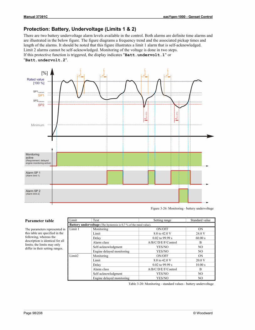
Manual 37391C easYgen-1000 - Genset Control
Page 98/208 © Woodward
Protection: Battery, Undervoltage (Limits 1 & 2) There are two battery undervoltage alarm levels available in the control. Both alarms are definite time alarms and are illustrated in the below figure. The figure diagrams a frequency trend and the associated pickup times and length of the alarms. It should be noted that this figure illustrates a limit 1 alarm that is self-acknowledged. Limit 2 alarms cannot be self-acknowledged. Monitoring of the voltage is done in two steps. If this protective function is triggered, the display indicates "Batt.undervolt.1" or "Batt.undervolt.2".
Figure 3-26: Monitoring - battery undervoltage
Parameter table The parameters represented in this table are specified in the following, whereas the description is identical for all limits; the limits may only differ in their setting ranges.
Limit Text Setting range Standard value Battery undervoltage (The hysteresis is 0,7 % of the rated value). Limit 1 Monitoring ON/OFF ON Limit 8.0 to 42.0 V 24.0 V
Delay 0.02 to 99.99 s 60.00 s Alarm class A/B/C/D/E/F/Control B Self-acknowledgment YES/NO NO Engine delayed monitoring YES/NO NO
Limit2 Monitoring ON/OFF ON Limit 8.0 to 42.0 V 20.0 V
Delay 0.02 to 99.99 s 10.00 s Alarm class A/B/C/D/E/F/Control B Self-acknowledgment YES/NO NO Engine delayed monitoring YES/NO NO
Table 3-20: Monitoring - standard values - battery undervoltage
[%]
Monitoringactive(Requirement: delayedengine monitoring active)
Minimum
SP2Hysteresis
SP1Hysteresis
Rated value[100 %]
Alarm SP 1(Alarm limit 1)
Alarm SP 2(Alarm limit 2)
t [min
-SP1
]
t [min
-SP1
]
t [min
-SP
2]
SP1
SP2t [m
in-S
P1]
t [min
-SP1
]
t [min
-SP
2]

Manual 37391C easYgen-1000 - Genset Control
© Woodward Page 99/208
EN
Monitoring Battery undervoltage: Monitoring (Limit 1/Limit 2) ON / OFF
ON ................ Undervoltage monitoring of the battery voltage is carried out according to the following parameters.
OFF .............. Monitoring is disabled for limit 1 and/or limit 2. DE
Überwachung 215
0 1o 1oc 2oc
EN
Limit Battery undervoltage: Threshold value (Limit 1/Limit 2) 8.0 to 42.0 V
The threshold values that are to be monitored are defined here. If the monitored battery voltage reaches or falls below this value for at least the delay time without interruption, the action specified by the alarm class is initiated. Note The default monitoring limit for battery undervoltage is 24 Vdc after 60 seconds. This is because in normal operation the terminal voltage is approximately 26 Vdc (alternator charged battery).
DE
Limit 216
0 1o 1oc 2oc
EN
Delay Battery undervoltage: Delay time (Limit 1/Limit 2) 0.02 to 99.99 s
If the battery voltage falls below the threshold value for the delay time configured here, an alarm will be issued. If the battery voltage exceeds the threshold (plus the hysteresis) again before the delay expires the time will be reset.
DE
Verzögerung 217
0 1o 1oc 2oc
EN
Alarm class Battery undervoltage: Alarm class (Limit 1/Limit 2) Class A/B/C/D/E/F/Control
See chapter "Alarm" on page 138. The alarm class assigned to each limit alarm.
DE
Alarmklasse 218
0 1o 1oc 2oc
EN
Self acknowledge Battery undervoltage: Self acknowledgment (Limit 1/Limit 2) YES / NO
YES .............. The control automatically clears the alarm if it is no longer valid. NO ................ An automatic reset of the alarm does not occur. The reset occurs
manually by pressing the appropriate buttons, by activating the LogicsManager output "External acknowledgement" via an discrete input, or via an interface.
DE
Selbstquittierend 219
0 1o 1oc 2oc
EN
Delayed by engine speed Battery undervoltage: Engine delayed monitoring (Limit 1/Limit 2) YES / NO
YES .............. The alarm is delayed until engine monitoring is enabled. Therefore the conditions of Parameter 60 "Engine delayed monitoring" must be fulfilled.
NO ................ The alarm is not delayed until engine monitoring is enabled. Fault conditions are immediately analyzed.
DE
Verzögert durch Motordrehz. 220
0 1o 1oc 2oc

Manual 37391C easYgen-1000 - Genset Control
Page 100/208 © Woodward
Protection: CANopen Interface, Monitoring The CANopen interface is monitored. If the interface does not receive a CANopen protocol message before the delay expires, an alarm will be initiated. If this protective function is triggered, the display indicates "CAN Open Fault".
EN
Monitoring CANopen Interface: Monitoring ON / OFF
ON ................Monitoring of the CANopen interface is carried out according to the following parameters.
OFF ..............Monitoring is disabled.
DE
Überwachung 221
0 1o 1oc 2oc
EN
Delay CANopen Interface: Delay 0.1 to 650.0 s
The delay is configured with this parameter. If the interface does not receive a CANopen protocol message before the delay expires, the action specified by the alarm class is initiated. The delay timer is re-initialized after every message is received.
DE
Verzögerung 222
0 1o 1oc 2oc
EN
Alarm class CANopen Interface: Alarm class Class A/B/C/D/E/F
See chapter "Alarm" on page 138. The alarm class assigned to each limit alarm.
DE
Alarmklasse 223
0 1o 1oc 2oc
EN
Self acknowledge CANopen Interface: Self acknowledgment YES / NO
YES ..............The control automatically clears the alarm if it is no longer valid. NO ................An automatic reset of the alarm does not occur. The reset occurs
manually by pressing the appropriate buttons, by activating the LogicsManager output "External acknowledgement" via an discrete input, or via an interface.
DE
Selbstquittierend 224
0 1o 1oc 2oc
EN
Delayed by engine speed CANopen Interface: Engine delayed YES / NO
YES ..............The alarm is delayed until engine monitoring is enabled. Therefore the conditions of Parameter 60 "Engine delayed monitoring" must be fulfilled.
NO ................The alarm is not delayed until engine monitoring is enabled. Fault conditions are immediately analyzed.
DE
Verzögert durch Motordrehz. 225
0 1o 1oc 2oc
NOTE This protection is only available if an external digital I/O board (e.g. IKD 1) is connected.
Manual 37391C easYgen-1000 - Genset Control
© Woodward Page 101/208
Protection: J1939 Interface, Monitoring This watchdog triggers if the easYgen is configured to receive J1939 data from an ECU (Parameter 339) connected to the CAN bus to evaluate these data, and no data is received from the ECU. If this protective function is triggered, the display indicates "CAN-Fault J1939".
EN
Monitoring J1939 Interface: Monitoring ON / OFF
ON ................ Monitoring of the J1939 interface is carried out according to the following parameters.
OFF .............. Monitoring is disabled.
DE
Überwachung 226
0 1o 1oc 2oc
EN
Delay J1939 Interface: Delay 0.1 to 650.0 s
The delay is configured with this parameter. If the interface does not receive a CAN SAE J1939 protocol message before the delay expires, the action specified by the alarm class is initiated. The delay timer is re-initialized after every message is received.
DE
Verzögerung 227
0 1o 1oc 2oc
EN
Alarm class J1939 Interface: Alarm class Class A/B/C/D/E/F
See chapter "Alarm" on page 138. The alarm class assigned to each limit alarm.
DE
Alarmklasse 228
0 1o 1oc 2oc
EN
Self acknowledge J1939 Interface: Self acknowledgment YES / NO
YES .............. The control automatically clears the alarm if it is no longer valid. NO ................ An automatic reset of the alarm does not occur. The reset occurs
manually by pressing the appropriate buttons, by activating the LogicsManager output "External acknowledgement" via an discrete input, or via an interface.
DE
Selbstquittierend 229
0 1o 1oc 2oc
EN
Delayed by engine speed J1939 Interface: Engine delayed YES / NO
YES .............. The alarm is delayed until engine monitoring is enabled. Therefore the conditions of Parameter 60 "Engine delayed monitoring" must be fulfilled.
NO ................ The alarm is not delayed until engine monitoring is enabled. Fault conditions are immediately analyzed.
DE
Verzögert durch Motordrehz. 230
0 1o 1oc 2oc
NOTE This protection is only available if an engine control is connected which communicates with the easYgen using the J1939 protocol.
Manual 37391C easYgen-1000 - Genset Control
Page 102/208 © Woodward
Protection: J1939 Interface, Amber Warning Lamp DM1 This watchdogs monitors, whether a specific alarm bit is received from the CAN J1939 interface. This enables to configure the easYgen in a way that a reaction is caused by this bit (e.g. warning, shutdown). If this protective function is triggered, the display indicates "Amber warning lamp".
EN
Monitoring J1939 Interface: Amber warning lamp DM1: Monitoring ON / OFF
ON ................Monitoring of the Amber Warning Lamp message from the ECU is carried out according to the following parameters.
OFF ..............Monitoring is disabled.
DE
Überwachung 231
0 1o 1oc 2oc
EN
Delay J1939 Interface: Amber warning lamp DM1: Delay 0.1 to 650.0 s
The amber warning lamp delay is configured with this parameter. If the ECU sends the Amber Warning Lamp ON message, the action specified by the alarm class is initiated after the delay configured here expires.
DE
Verzögerung 232
0 1o 1oc 2oc
EN
Alarm class J1939 Interface: Amber warning lamp DM1: Alarm class Class A/B/C/D/E/F/Control
See chapter "Alarm" on page 138. The alarm class assigned to each limit alarm.
DE
Alarmklasse 233
0 1o 1oc 2oc
EN
Self acknowledge J1939 Interface: Amber warning lamp DM1: Self acknowledgment YES / NO
YES ..............The control automatically clears the alarm if it is no longer valid. NO ................An automatic reset of the alarm does not occur. The reset occurs
manually by pressing the appropriate buttons, by activating the LogicsManager output "External acknowledgement" via an discrete input, or via an interface.
DE
Selbstquittierend 234
0 1o 1oc 2oc
EN
Delayed by engine speed J1939 Interface: Amber warning lamp DM1: Engine delayed YES / NO
YES ..............The alarm is delayed until engine monitoring is enabled. Therefore the conditions of Parameter 60 "Engine delayed monitoring" must be fulfilled.
NO ................The alarm is not delayed until engine monitoring is enabled. Fault conditions are immediately analyzed.
DE
Verzögert durch Motordrehz. 235
0 1o 1oc 2oc
NOTE This protection is only available if an engine control is connected which communicates with the easYgen using the J1939 protocol.
Manual 37391C easYgen-1000 - Genset Control
© Woodward Page 103/208
Protection: J1939 Interface, Red Stop Lamp DM1 This watchdogs monitors, whether a specific alarm bit is received from the CAN J1939 interface. This enables to configure the easYgen in a way that a reaction is caused by this bit (e.g. warning, shutdown). If this protective function is triggered, the display indicates "Red stop lamp".
EN
Monitoring J1939 Interface: Red stop lamp DM1: Monitoring ON / OFF
ON ................ Monitoring of the Red Stop Lamp message from the ECU is carried out according to the following parameters.
OFF .............. Monitoring is disabled.
DE
Überwachung 236
0 1o 1oc 2oc
EN
Delay J1939 Interface: Red stop lamp DM1: Delay 0.1 to 650.0 s
The red stop lamp delay is configured with this parameter. If the ECU sends the Red Stop Lamp ON message, the action specified by the alarm class is initiated after the delay configured here expires.
DE
Verzögerung 237
0 1o 1oc 2oc
EN
Alarm class J1939 Interface: Red stop lamp DM1: Alarm class Class A/B/C/D/E/F/Control
See chapter "Alarm" on page 138. The alarm class assigned to each limit alarm.
DE
Alarmklasse 238
0 1o 1oc 2oc
EN
Self acknowledge J1939 Interface: Red stop lamp DM1: Self acknowledgment YES / NO
YES .............. The control automatically clears the alarm if it is no longer valid. NO ................ An automatic reset of the alarm does not occur. The reset occurs
manually by pressing the appropriate buttons, by activating the LogicsManager output "External acknowledgement" via an discrete input, or via an interface.
DE
Selbstquittierend 239
0 1o 1oc 2oc
EN
Delayed by engine speed J1939 Interface: Red stop lamp DM1: Engine delayed YES / NO
YES .............. The alarm is delayed until engine monitoring is enabled. Therefore the conditions of Parameter 60 "Engine delayed monitoring" must be fulfilled.
NO ................ The alarm is not delayed until engine monitoring is enabled. Fault conditions are immediately analyzed.
DE
Verzögert durch Motordrehz. 240
0 1o 1oc 2oc
NOTE This protection is only available if an engine control is connected which communicates with the easYgen using the J1939 protocol.

Manual 37391C easYgen-1000 - Genset Control
Page 104/208 © Woodward
Discrete Inputs ≡≡≡≡≡≡≡≡≡≡≡≡≡≡≡≡≡≡≡≡≡≡≡≡≡
Number Terminal Application mode
0 1o 1oc 2oc Internal discrete inputs
[D1] 51 Alarm input (LogicsManager), pre-assigned with EMERGENCY OFF [D2] 52 Alarm input (LogicsManager), pre-assigned with Start in AUTO [D3] 53 Alarm input (LogicsManager) [D4] 54 Alarm input (LogicsManager) [D5] 55 Alarm input (LogicsManager) [D6] 56 Alarm input (LogicsManager) Enable MCB #1 [D7] 57 Alarm input (LogicsManager) Reply: MCB is open [D8] 58 Alarm input (LogicsManager) Reply: GCB is open Reply: GCB is open
External discrete inputs (via CANopen; not included in easYgen delivery; can be e.g. IKD1, etc.) [DEx01] --- Alarm input (LogicsManager) [DEx02] --- Alarm input (LogicsManager) [DEx03] --- Alarm input (LogicsManager) [DEx04] --- Alarm input (LogicsManager) [DEx05] --- Alarm input (LogicsManager) [DEx06] --- Alarm input (LogicsManager) [DEx07] --- Alarm input (LogicsManager) [DEx08] --- Alarm input (LogicsManager) [DEx09] --- Alarm input (LogicsManager) [DEx10] --- Alarm input (LogicsManager) [DEx11] --- Alarm input (LogicsManager) [DEx12] --- Alarm input (LogicsManager) [DEx13] --- Alarm input (LogicsManager) [DEx14] --- Alarm input (LogicsManager) [DEx15] --- Alarm input (LogicsManager) [DEx16] --- Alarm input (LogicsManager)
#1..If the parameter Enable MCB is configured to ALWAYS, this DI may be used as alarm input (LogicsManager)
Table 3-21: Discrete inputs - assignment
NOTE Alarm inputs may also be configured as control inputs and then be used as command variables in the LogicsManager.
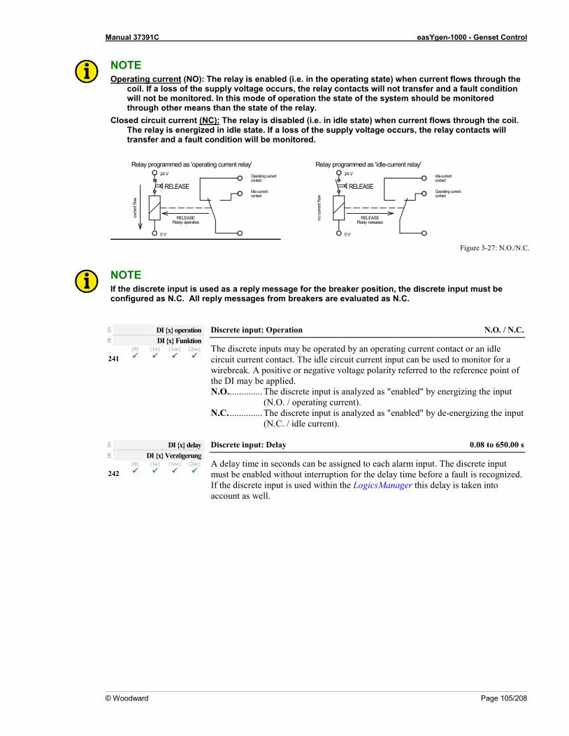
Manual 37391C easYgen-1000 - Genset Control
© Woodward Page 105/208
NOTE Operating current (NO): The relay is enabled (i.e. in the operating state) when current flows through the
coil. If a loss of the supply voltage occurs, the relay contacts will not transfer and a fault condition will not be monitored. In this mode of operation the state of the system should be monitored through other means than the state of the relay.
Closed circuit current (NC): The relay is disabled (i.e. in idle state) when current flows through the coil. The relay is energized in idle state. If a loss of the supply voltage occurs, the relay contacts will transfer and a fault condition will be monitored.
Figure 3-27: N.O./N.C.
NOTE If the discrete input is used as a reply message for the breaker position, the discrete input must be configured as N.C. All reply messages from breakers are evaluated as N.C.
EN
DI x operation Discrete input: Operation N.O. / N.C.
The discrete inputs may be operated by an operating current contact or an idle circuit current contact. The idle circuit current input can be used to monitor for a wirebreak. A positive or negative voltage polarity referred to the reference point of the DI may be applied. N.O. .............. The discrete input is analyzed as "enabled" by energizing the input
(N.O. / operating current). N.C. .............. The discrete input is analyzed as "enabled" by de-energizing the input
(N.C. / idle current).
DE
DI x Funktion 241
0 1o 1oc 2oc
EN
DI x delay Discrete input: Delay 0.08 to 650.00 s
A delay time in seconds can be assigned to each alarm input. The discrete input must be enabled without interruption for the delay time before a fault is recognized. If the discrete input is used within the LogicsManager this delay is taken into account as well.
DE
DI x Verzögerung 242
0 1o 1oc 2oc
Relay programmed as 'operating current relay'Operating currentcontact
Idle-currentcontact
curre
nt fl
ow
0 V
RELEASERelay operates
24 V
RELEASEOperating currentcontact
Idle-currentcontact
RELEASERelay releases
no c
urre
nt fl
ow
0 V
Relay programmed as 'idle-current relay'
RELEASE
24 V

Manual 37391C easYgen-1000 - Genset Control
Page 106/208 © Woodward
EN
DI x alarm class Discrete input: Alarm class Class A/B/C/D/E/F/Control
see chapter "Alarm Classes" on page 138. An alarm class may be assigned to the discrete input. The alarm class is executed when the discrete input is enabled. If "control" has been configured as alarm class a function out of the LogicsManager (description at page 139) can be assigned to the discrete inputs. There will be no entry in the event history in case of an alarm.
DE
DI x Alarmklasse 243
0 1o 1oc 2oc
EN
DI x delayed by eng.speed Discrete input: Engine delayed monitoring YES / NO
YES ..............The alarm is delayed until engine monitoring is enabled. Therefore the conditions of Parameter 60 "Engine delayed monitoring" must be fulfilled.
NO ................The alarm is not delayed until engine monitoring is enabled. Fault conditions are immediately analyzed.
DE
DI x verzög. d. Motordrehz. 244
0 1o 1oc 2oc
NOTE If a discrete input has been configured with a shut-down alarm that has been enabled to self-acknowledge, and has been configured as engine delayed the following scenario may happen: • The discrete input shuts down the engine because of its alarm class. • Due to the engine stopping, all engine delayed alarms are ignored. • The alarm class is acknowledged automatically. • The alarm will self-acknowledge and clear the fault message that shut the engine down. This
prevents the fault from being analyzed. After a short delay, the engine will restart. • After the engine monitoring delay expires, the fault that originally shut down the engine will do so
again. This cycle will continue to repeat until corrected.
EN
DI x self acknowledge Discrete input: Self acknowledgment YES / NO
YES ..............The control automatically clears the alarm if it is no longer valid. NO ................An automatic reset of the alarm does not occur. The reset occurs
manually by pressing the appropriate buttons, by activating the LogicsManager output "External acknowledgement" via an discrete input, or via an interface.
If the DI is configured with the alarm class "Control", self acknowledgement is always active.
DE
DI x Selbstquittierend 245
0 1o 1oc 2oc
EN
DI x text Discrete input: Message text user-defined
If the discrete input is enabled, this text is displayed on the control unit screen. The event log will store this text message as well. Note: This parameter may only be configured using LeoPC1. Note: If the DI is used as control input with the alarm class "Control", you may enter here its function (e.g. external acknowledgement) for a better overview within the configuration.
DE
DI x Text L 246
0 1o 1oc 2oc

Manual 37391C easYgen-1000 - Genset Control
© Woodward Page 107/208
Discrete Outputs (LogicsManager) ≡≡≡≡≡≡≡≡≡≡≡≡≡≡≡≡≡≡≡≡≡≡≡≡≡
The discrete outputs are controlled via the LogicsManager. Please note the description of the LogicsManager starting on page 140. Some outputs are assigned a function according to the application mode (see following table). Relay Application mode Number Term. Basic
0 GCB open
1o GCB open/close
1oc GCB/MCB open/close
2oc Internal relay outputs [R1] 30/35 LogicsManager [R2] 31/35 LogicsManager [R3] 32/35 Crank [R4] 33/35 Diesel: Fuel solenoid
Gas: Gas valve [R5] 34/35 LogicsManager; pre-assigned with 'Diesel: Pre-glow, Gas: Ignition' [R6] 36/37 LogicsManager; pre-assigned with 'Auxiliary services' [R7] 38/39 LogicsManager Command: open GCB [R8] 40/41 LogicsManager Command: close MCB [R9] 42/43 LogicsManager Command: open MCB [R10] 44/45 LogicsManager Command: close GCB [R11] 46/47 Ready for operation / LogicsManager External relay output (via CANopen; not included in easYgen delivery; can be an expansion card like IKD1) [REx01] --- LogicsManager [REx02] --- LogicsManager [REx03] --- LogicsManager [REx04] --- LogicsManager [REx05] --- LogicsManager [REx06] --- LogicsManager [REx07] --- LogicsManager [REx08] --- LogicsManager [REx09] --- LogicsManager [REx10] --- LogicsManager [REx11] --- LogicsManager [REx12] --- LogicsManager [REx13] --- LogicsManager [REx14] --- LogicsManager [REx15] --- LogicsManager [REx16] --- LogicsManager
#1..The relay has superimposed the "Ready for operation" information and operates as idle current relay (N.C.)
Table 3-22: Relay outputs - assignment
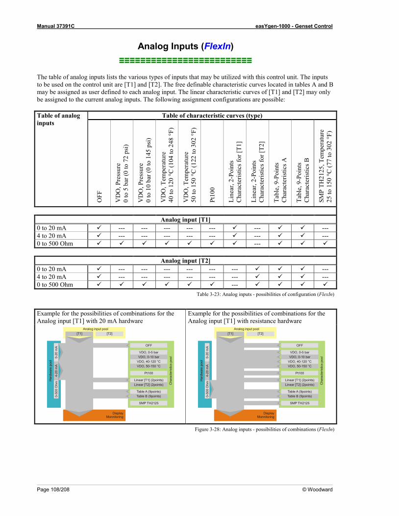
Manual 37391C easYgen-1000 - Genset Control
Page 108/208 © Woodward
Analog Inputs (FlexIn) ≡≡≡≡≡≡≡≡≡≡≡≡≡≡≡≡≡≡≡≡≡≡≡≡≡
The table of analog inputs lists the various types of inputs that may be utilized with this control unit. The inputs to be used on the control unit are [T1] and [T2]. The free definable characteristic curves located in tables A and B may be assigned as user defined to each analog input. The linear characteristic curves of [T1] and [T2] may only be assigned to the current analog inputs. The following assignment configurations are possible: Table of analog inputs
Table of characteristic curves (type)
OFF
VD
O, P
ress
ure
0 to
5 b
ar (0
to 7
2 ps
i)
VD
O, P
ress
ure
0 to
10
bar (
0 to
145
psi
)
VD
O, T
empe
ratu
re
40 to
120
°C (1
04 to
248
°F)
VD
O, T
empe
ratu
re
50 to
150
°C (1
22 to
302
°F)
Pt10
0
Line
ar, 2
-Poi
nts
Cha
ract
eris
tics f
or [T
1]
Line
ar, 2
-Poi
nts
Cha
ract
eris
tics f
or [T
2]
Tabl
e, 9
-Poi
nts
Cha
ract
eris
tics A
Tabl
e, 9
-Poi
nts
Cha
ract
eris
tics B
SMP
TH21
25, T
empe
ratu
re
25 to
150
°C (7
7 to
302
°F)
Analog input [T1]
0 to 20 mA --- --- --- --- --- --- --- 4 to 20 mA --- --- --- --- --- --- --- 0 to 500 Ohm ---
Analog input [T2] 0 to 20 mA --- --- --- --- --- --- --- 4 to 20 mA --- --- --- --- --- --- --- 0 to 500 Ohm ---
Table 3-23: Analog inputs - possibilities of configuration (FlexIn)
Example for the possibilities of combinations for the Analog input [T1] with 20 mA hardware
Example for the possibilities of combinations for the Analog input [T1] with resistance hardware
Figure 3-28: Analog inputs - possibilities of combinations (FlexIn)
[T1] [T2]
0-20
mA
0-50
0 O
hm
VDO, 0-5 barVDO, 0-10 bar
VDO, 40-120 °CVDO, 50-150 °C
Pt100
SMP TH2125
4-20
mA
DisplayMonnitoring
OFF
Analog input pool
Har
dwar
e po
ol
Cha
ract
eris
tics
pool
Linear [T1] (2points)
Table A (9points)Table B (9points)
Linear [T2] (2points)
[T1] [T2]
0-20
mA
0-50
0 O
hm
VDO, 0-5 barVDO, 0-10 bar
VDO, 40-120 °CVDO, 50-150 °C
Pt100
SMP TH2125
4-20
mA
DisplayMonnitoring
OFF
Analog input pool
Har
dwar
e po
ol
Cha
ract
eris
tics
pool
Linear [T1] (2points)
Table A (9points)Table B (9points)
Linear [T2] (2points)

Manual 37391C easYgen-1000 - Genset Control
© Woodward Page 109/208
Analog Inputs: Display
EN
Display temperature in Temperature display in °C / °F
°C ....................... The temperature is displayed in °C (Celsius). °F........................ The temperature is displayed in °F (Fahrenheit).
DE
Temperaturanzeige in 247
0 1o 1oc 2oc
EN
Display pressure in Pressure display in bar / psi
bar ...................... The pressure is displayed in Bar. psi ....................... The pressure is displayed in psi.
DE
Druckanzeige in 248
0 1o 1oc 2oc
NOTE These parameters define only the display. Monitoring of the limits is always performed with the engineering units °C or bar.
Analog Inputs: Type
EN
Type Analog input x [x = 1 or 2]: Type OFF / VDO 5bar / VDO 10bar / VDO 120°C / VDO 150°C / Pt100 / linear / Table A / Table B
The characteristic curves of the inputs can be found in Appendix C (page 168).
According to the following parameters different measuring ranges are possible at the analog inputs. The selectable ranges are: OFF .................... The analog input is switched off. VDO 5bar .......... The value of the analog input is interpreted with the VDO
characteristics 0 to 5 bar. VDO 10bar ........ The value of the analog input is interpreted with the VDO
characteristics 0 to 10 bar. VDO 120°C ....... The value of the analog input is interpreted with the VDO
characteristics 40 to 120 °C. VDO 150°C ....... The value of the analog input is interpreted with the VDO
characteristics 50 to 150 °C. Pt100 .................. The value of the analog input is interpreted with a Pt100
characteristic. linear .................. Each analog input may be assigned to a linear characteristic
curve, which can be only used for the respective defined input [Tx] (x = 1 to 2). The minimum (0 %) and maximum (100 %) value refers to the total measuring range of the analog input (i.e. 0 to 500 Ohm, 0 to 20 mA or 4 to 20 mA). Both benchmark limits of the linear characteristic curves must be defined only in case they are used.
Table A / B ........ The analog input is assigned to a characteristic curve which is defined over 9 points (stored in a table). Two independent tables (table A and table B) may be allocated to the analog inputs. Note that if these tables are to be used with the analog inputs, the defined points of these tables must be programmed into the control unit.
SMP 2125 .......... The value of the analog input is interpreted with a SMP TH2125 characteristic.
DE
Typ 249
0 1o 1oc 2oc

Manual 37391C easYgen-1000 - Genset Control
Page 110/208 © Woodward
EN
Select hardware Analog input x [x = 1 or 2]: Hardware 0 to 500 Ohm / 0 to 20 mA / 4 to 20 mA
The software in the control unit may be configured for various types of sensors. The configurable ranges apply to the linear analog input. Configurable ranges are: 0 to 500 Ohm The measuring range of the analog input is 0- to 500 Ohm.
0 Ohm = 0 %, 500 Ohm = 100 %. 0 to 20 mA ....The measuring range of the analog input is 0 to 20 mA.
0 mA = 0 %, 20 mA = 100 %. 4 to 20 mA ....The measuring range of the analog input is 4 to 20 mA.
4 mA = 0 %, 20 mA = 100 %.
DE
Auswahl Hardware 250
0 1o 1oc 2oc
EN
Offset Analog input x [x = 1 or 2]: Offset -20.0 to 20.0 Ohm
The resistive input (the "0-500Ohm" analog input) may be calculated with a permanent offset to adjust for inaccuracies. If the offset feature is utilized, the value configured in this parameter will be added to/subtracted from the measured resistive value. This has the following effect to the measured values (please note tables starting on page 168): -20.0 to 0.1 Ohm
VDO temperature: The displayed value will decrease. VDO pressure: The displayed value will increase.
+0.1 to 20.0 Ohm VDO temperature: The displayed value will increase. VDO pressure: The displayed value will decrease.
DE
Offset 251
0 1o 1oc 2oc
EN
Bargraph minimum Analog input x [x = 1 or 2]: Bar graph minimum value -9999 to 9999
The start value for the bar graph display of the analog input is defined here. The value must be entered according to the display format, which refers to the analog input type (Parameter 249). Note: This parameter is only effective if Parameter 249 is configured to Linear or Table A/B.
DE
Bargraph Minimum 252
0 1o 1oc 2oc
EN
Bargraph maximum Analog input x [x = 1 or 2]: Bar graph maximum value -9999 to 9999
The end value for the bar graph display of the analog input is defined here. The value must be entered according to the display format, which refers to the analog input type (Parameter 249). Note: This parameter is only effective if Parameter 249 is configured to Linear or Table A/B.
DE
Bargraph Maximum 253
0 1o 1oc 2oc
EN
Description Analog input x [x = 1 or 2]: Message text user-defined
If the programmed limit value of the analog input has been reached or exceeded this text is displayed in the control unit screen. The event log will store this text message and it is also used for the visualization screen. Note: This parameter may only be configured using LeoPC1.
DE
Beschreibung L 254
0 1o 1oc 2oc

Manual 37391C easYgen-1000 - Genset Control
© Woodward Page 111/208
EN
Value format Analog input x [x = 1 or 2]: Value format user-defined
If a sign to denote a negative measured value (i.e. –10) is required, then the first "0" of the numeric display is utilized for this symbol.
To display the measuring value of the analog input for the analog input types linear as well as Table A and Table B (Parameter 249) correctly this parameter is to be used to define the format. The zeros in the numeric display are used for the measuring values and are configurable. The placeholders for the digits may have symbols (i.e. commas). Note • This parameter may only be configured using LeoPC1. • This parameter only applies to the linear and the user defined Table A and Table
B (Parameter 249) analog input types. • The displayed value should be configured with the same number of digits as the
desired value to be measured. • The measured value will be displayed from right to left. If the measured value is
larger than the number of digits in the display, only a portion of the measured value will be shown. An example of this would be a display of three digits is configured when four digits will be needed. Instead of the number "1234" being displayed only "234" will be shown.
• If the parameter being displayed has a numeral "0" in the name, the letter "O" must be used instead. If a numeral is used, a numeric value will display in its place.
Examples Fuel level - value at 0 % .............. 0 - value at 100 % .......... 1000 - desired display ......... up to 1,000mm - this parameter ........... 0,000mm Angle - value at 0 % .............. -1799 - value at 100 % .......... 1800 - desired display ......... -179.9° to 180.0° - this parameter ........... 0000.0° Pressure - value at 0 % .............. 0 - value at 100 % .......... 100 - desired display ......... up to 10.0bar - this parameter ........... 00.0bar
DE
Zahlenformat L 255
0 1o 1oc 2oc

Manual 37391C easYgen-1000 - Genset Control
Page 112/208 © Woodward
EN
Filter time constant Analog input x [x = 1 or 2]: Filter time constant OFF / 1 / 2 / 3 / 4 / 5
A filter time constant may be used to reduce the fluctuation of an analog input reading. This filter time constant assesses the average of the signal according to the following formula:
122201
−×××=−− Nms
frequencyoffCutπ
, whereby "N" is the parameter.
OFF ..............The analog input is displayed without filtering. 1 ....................Cut-off-frequency = 7.96 Hz (filter time constant = 0.02 s) 2 ....................Cut-off-frequency = 3.98 Hz (filter time constant = 0.04 s) 3 ....................Cut-off-frequency = 1.99 Hz (filter time constant = 0.08 s) 4 ....................Cut-off-frequency = 0.99 Hz (filter time constant = 0.16 s) 5 ....................Cut-off-frequency = 0.50 Hz (filter time constant = 0.32 s)
DE
Filter 256
0 1o 1oc 2oc
EN
Hysteresis Scaling linear x [x = A/B]: Hysteresis 0 to 999
If the analog input is used for monitoring/protection the actual value must exceed or fall below one of the limits defined in Parameter 259 and/or 260 to be recognized as out of parameters. For a value to register as having returned to be within parameters, the monitored value must rise above or fall below this value for the hysteresis.
DE
Hysterese 257
0 1o 1oc 2oc
NOTE The setting of the hysteresis is only valid for the fixed assigned thresholds. When using flexible thresholds, an own hysteresis (Parameter 279) must be defined. The setting of this parameter has no effect with flexible thresholds.
Analog Inputs: Monitoring Limits Monitoring of the respective analog input is performed according to the configuration. If this protective function is triggered, the display indicates "Lv1: Text of Parameter 254" or "Lv2: Text of Parameter 254".
EN
Monitoring level y Analog input x [x = 1 or 2]: Monitoring threshold value y [y = 1/2] ON / OFF
ON ................Limit(s) 1 and/or 2 are enabled and monitoring of following parameter is limits carried out. Both limits can be enabled independent of each other.
OFF ..............Monitoring is disabled.
DE
Überwachung Stufey 258
0 1o 1oc 2oc
EN
Limit level y Analog input x [x = 1 or 2]: Threshold value y [y = 1/2] -9,999 to 9,999
The limit of the value to be monitored is defined by this parameter. If this value is reached or exceeded / fallen below (dependent on Parameter 262) for at least the delay time configured in Parameter 261 the action ispecified by the alarm class is initiated after the configured delay expires. Entering the limits may only be performed in the engineering units °C or bar, not in °F or psi.
DE
Limit Stufey 259
0 1o 1oc 2oc
EN
Limit level y Idle Run Analog input x [x = 1 or 2]: Idle mode threshold value y [y = 1/2] -9,999 to 9,999
See Engine: Idle Mode on page 43. If the engine idle mode is enabled, an alternative threshold value is configured here. This threshold is used instead of the threshold defined in Parameter 259 while the idle mode is active.
DE
Limit Stufey Idle Modus 260
0 1o 1oc 2oc

Manual 37391C easYgen-1000 - Genset Control
© Woodward Page 113/208
EN
Delay levely Analog input x [x = 1 or 2]: Delay time threshold value y [y = 1/2] 0.02 to 99.99 s
If the monitored analog input value exceeds or falls below the threshold value for the delay time configured here, an alarm will be issued. If the monitored analog input value falls below or exceeds (dependent on Parameter 262) the threshold (plus/minus the hysteresis) before the delay expires the time will be reset.
DE
Verzögerung Stufe y 261
0 1o 1oc 2oc
EN
Monitoring level y at Analog input x [x = 1 or 2]: Monitoring limit y [y = 1/2] on Overrun / Underrun
Overrun ....... So that the actual value is identified as reached it must have rised over the limit.
Underrun..... So that the actual value is identified as reached it must have fallen below the limit.
DE
Überwachung Stufey auf 262
0 1o 1oc 2oc
EN
Alarm class level y Analog in.x [x = 1 or 2]: Alarm cl.. limit y [y = 1/2] Class A/B/C/D/E/F
See chapter "Alarm" on page 138. The alarm class assigned to each limit alarm.
DE
Alarmklasse Stufe y 263
0 1o 1oc 2oc
EN
Self acknowledge level y Analog input x [x = 1 or 2]: Self acknowledged limit y [y = 1/2] YES / NO
YES .............. The control automatically clears the alarm if it is no longer valid. NO ................ An automatic reset of the alarm does not occur. The reset occurs
manually by pressing the appropriate buttons, by activating the LogicsManager output "External acknowledgement" via an discrete input, or via an interface.
DE
Selbstquittierend Stufe y 264
0 1o 1oc 2oc
EN
Delayed by engine level y Analog input x [x = 1 or 2]: Engine delayed monitoring y [y = 1/2] YES / NO
YES .............. The alarm is delayed until engine monitoring is enabled. Therefore the conditions of Parameter 60 "Engine delayed monitoring" must be fulfilled.
NO ................ The alarm is not delayed until engine monitoring is enabled. Fault conditions are immediately analyzed.
DE
Verzögert d. Motordr. St. y 265
0 1o 1oc 2oc

Manual 37391C easYgen-1000 - Genset Control
Page 114/208 © Woodward
Analog Inputs: Wire Break Monitoring The respective analog input is monitored for wire break. If this protective function is triggered, the display indicates "Wb: Text of Parameter 254".
EN
Monitoring wire break Analog input x [x = 1 or 2]: Wire break monitoring Off / High / Low / high/low
The analog input can be monitored for a wire break. The following configurations are used to monitor for a wire break: Off ................No wire break monitoring is performed. High ..............If the actual value rises over the maximum value (overshoot), this is
identified as a wire break. Low ...............If the actual value falls below the minimum value (undershoot), this
is identified as a wire break. high/low .......If the actual value rises over the maximum value (overshoot) or falls
below the minimum value (undershoot), this is identified as a wire break.
DE
Drahtbruchüberw. 266
0 1o 1oc 2oc
NOTE If the control unit detects that the measuring range for an analog input has been exceeded and an alarm is issued, the limit value monitoring of this analog input is disabled. The measuring range is recognized as being exceeded and an alarm is issued: • 4 to 20 mA
Minimum value ......... 2 mA ............... Undershooting Maximum value ........ 20.5 mA .......... Overshooting
• 0 to 500 Ohm Minimum value ......... 5 Ohm ............. Undershooting (Offset = 0 Ohm) Maximum value ........ 515 Ohm ......... Overshooting (Offset = 0 Ohm) Note: Depending on what was configured for the offset value (Parameter 251) the displayed value may be shifted. This may result in a broken wire being recognized early or later than the actual value being measured. (An offset of +20ohms will recognize a wire break at 25ohms instead of 5ohms.)
EN
Wire break alarm class Analog in. x [x = 1 or 2]: Alarm cl. wire break monit. Class A/B/C/D/E/F/Control
See chapter "Alarm" on page 138. The alarm class assigned to each limit alarm.
DE
Drahtbruch Alarmklasse 267
0 1o 1oc 2oc
EN
Self acknowledge wire break Analog input x [x = 1 or 2]: Self acknowledged YES / NO
YES ..............The control automatically clears the alarm if it is no longer valid. NO ................An automatic reset of the alarm does not occur. The reset occurs
manually by pressing the appropriate buttons, by activating the LogicsManager output "External acknowledgement" via an discrete input, or via an interface.
DE
Drahtbruch selbstquitt. 268
0 1o 1oc 2oc

Manual 37391C easYgen-1000 - Genset Control
© Woodward Page 115/208
Analog Inputs: Characteristics "Linear" (2 Point Scaling)
Figure 3-29: Analog input scaling - linear characteristics
EN
Value at 0% Scaling linear x [x = A/B]: Value at 0 % -9,999 to 9,999
The analog input is assigned to a straight line. This parameter defines the actual value at 0 % of the total range of the analog input. For example, the input is configured as a 0 to 20 mA input, 0 % equals 0 mA. If 4 to 20 mA is selected, 0 % equals 4 mA.
DE
Wert bei 0% 269
0 1o 1oc 2oc
EN
Value at 100% Scaling linear x [x = A/B]: Value at 100 % -9,999 to 9,999
The analog input is assigned to a straight line. This parameter defines the actual value at 100 % of the range of the analog input. For example, the input is configured as a 0 to 20 mA input, 100 % equals 20 mA.
DE
Wert bei 100% 270
0 1o 1oc 2oc
Analog Inputs: Configure Flexible Thresholds Monitoring of the respective limit is performed according to the configuration. If this protective function is triggered, the display indicates "Flexible Limit x", where x indicates the flexible limits 1 to 4, or the display indicates the text configured in Parameter 280.
EN
Monitoring Flexible limit x [x = 1 to 4]: Monitoring ON / OFF
ON ................ Monitoring of the flexible limit x is carried out according to the following parameters.
OFF .............. Monitoring is disabled.
DE
Überwachung 271
0 1o 1oc 2oc
[%]
y2
y1
0 100
Input
Value[corresponds]
600 kW
200 kW0.
0/4.
0 m
A =
200
kW 20.0
mA
= 60
0 kW
[mA]
[mA]
20.00.0
4.0 20.0
Range:0 to 20 mA
4 to 20 mA[Ohm]0.0 500.00 to 500 Ohm

Manual 37391C easYgen-1000 - Genset Control
Page 116/208 © Woodward
EN
Monitored analog input Flexible limit x [x = 1 to 4]: Monitored analog input see selection below
Battery .........The battery voltage is monitored with the flexible limit x. AnalogIn1 ....The analog input 1 is monitored with the flexible limit x. AnalogIn2 ....The analog input 2 is monitored with the flexible limit x. ECUSPN110 The coolant temperature from an ECU via the CAN bus is monitored
with the flexible limit x (J1939 SPN 110). ECUSPN100 The oil pressure from an ECU via the CAN bus is monitored with the
flexible limit x (J1939 SPN 100). ECUSPN190 The engine speed from an ECU via the CAN bus is monitored with
the flexible limit x (J1939 SPN 190).
DE
Überwachter Analogeingang 272
0 1o 1oc 2oc
EN
Limit Flexible limit x [x = 1 to 4]: Threshold -32000 to +32000
The threshold limit of the value to be monitored is defined by this parameter. If this value is reached or exceeded / fallen below (dependent on Parameter 275) for at least the delay time configured in Parameter 274 the action specified by the alarm class is initiated after the configured delay expires. The format for entering the threshold value depends on the monitored analog input: Battery .........Input in 0.1 V – example: 23.5 V > input: 00235 ECUSPN110 Direct input in °C – example: 156°C > input: 00156 ECUSPN100 Direct input in kPa – example: 600 kPa > input: 00600 ECUSPN190 Direct input in rpm – example: 1500 rpm > input: 01500 AnalogIn1/2 .Input depends on the configured format of the respective analog
input: VDO 5 bar ...Input in 0.01 bar/psi – example: 5.0 bar > input: 00500 * VDO 10 bar .Input in 0.01 bar/psi – example: 73.6 psi > input: 07360 * VDO 150°C ..Direct input in °C/F – example: 69°C > input: 00069 ** VDO 120°C ..Direct input in °C/F – example: 156°F > input: 00156 ** Pt100 ............Direct input in °C/F – example: 69°C > input: 00069 ** Linear ...........Input according to the configured format (Parameter 255) Tab. A/B .......Input according to the configured format (Parameter 255) SMP 2125 .....Direct input in °C/F – example: 73°C > input: 00073 **
* depending on the setting of Parameter 248 ** depending on the setting of Parameter 247
Examples Fuel level - value at 0 % ............. 0 - value at 100 % ......... 1000 - desired display ......... up to 1,000mm - this parameter .......... 0,000mm Angle - value at 0 % ............. -1799 - value at 100 % ......... 1800 - desired display ......... -179.9° to 180.0° - this parameter .......... 0000.0° Pressure - value at 0 % ............. 0 - value at 100 % ......... 100 - desired display ......... up to 10.0bar - this parameter .......... 00.0bar
DE
Limit 273
0 1o 1oc 2oc
Manual 37391C easYgen-1000 - Genset Control
© Woodward Page 117/208
EN
Delay Flexible limit x [x = 1 to 4]: Delay 00,02 to 99,99 s
If the monitored value exceeds or falls below the threshold value for the delay time configured here, an alarm will be issued. If the monitored value falls below the threshold (plus/minus the hysteresis, dependent on Parameter 275) before the delay expires the time will be reset.
DE
Verzögerung 274
0 1o 1oc 2oc
EN
Monitoring at Flexible limit x [x = 1 to 4]: Monitoring for Overrun / Underrun
Overrun ....... The monitored value must exceed the threshold limit for a fault to be recognized.
Underrun..... The monitored value must fall below the threshold limit for a fault to be recognized.
DE
Überwachung auf 275
0 1o 1oc 2oc
EN
Alarm class Flexible limit x [x = 1 to 4]: Alarm class Class A/B/C/D/E/F/Control
See chapter "Alarm" on page 138. The alarm class assigned to each limit alarm.
DE
Alarmklasse 276
0 1o 1oc 2oc
EN
Self acknowledge Flexible limit x [x = 1 to 4]: Self acknowledge YES / NO
YES .............. The control automatically clears the alarm if it is no longer valid. NO ................ An automatic reset of the alarm does not occur. The reset occurs
manually by pressing the appropriate buttons, by energizing the appropriate discrete input or via interface.
DE
Selbstquittierend 277
0 1o 1oc 2oc
EN
Delayed by engine speed Flexible limit x [x = 1 to 4]: Engine speed delay YES / NO
YES .............. The alarm is delayed until engine monitoring is enabled. Therefore the conditions of Parameter 60 "Engine delayed monitoring" must be fulfilled.
NO ................ The alarm is not delayed until engine monitoring is enabled. Fault conditions are immediately analyzed.
DE
Verzögert durch Motordrehz. 278
0 1o 1oc 2oc
EN
Hysteresis Flexible limit x [x = 1 to 4]: Hysteresis 0 to 999
During monitoring, the actual value must exceed or fall below one of the limits defined in parameter 273 to be recognized as out of permissible limits. For a value to register as having returned to the permissible limits, the monitored value must rise above or fall below this value for the hysteresis. The format for entering the hysteresis depends on the monitored analog input and corresponds with the one of the threshold listed in Parameter 273. Note: When using the flexible thresholds, the setting of Parameter 257 has no effect.
DE
Hysterese 279
0 1o 1oc 2oc
EN
Description Flexible limit x [x = 1 to 4]: Message text user-defined
If the configured threshold of the flexible analog input has been reached or exceeded the text configured here is displayed in the control unit screen (the default text is: Flexible Limit). The event log will store this text message and it is also used for the visualization screen. Note: This parameter may only be configured using LeoPC1.
DE
Beschreibung L 280
0 1o 1oc 2oc

Manual 37391C easYgen-1000 - Genset Control
Page 118/208 © Woodward
Analog Inputs: Characteristics "Table A" And "Table B" (9 Point Scaling) The characteristic curves of "Table A" and "Table B" (freely configurable over 9 defined percentage points) are independently configurable for all analog inputs. Each percentage point may be scaled to related values measured from the analog input (0 to 500 Ohm, 0 to 20 mA or 4 to 20 mA), so that the actual display reflects the measured values (i.e. -100 to 100 kW). The so developed characteristic curve can be used for visualization and monitoring via the configuration to "Table A" (for Table A) as well as "Table B" (for Table B)
Figure 3-30: Analog input scaling - table (example)
NOTE The X and Y junction may be moved within the range of values (the junctions don't have to be equidistant). When configuring the X coordinates, ensure the coordinates always increase in scale continuously. In the following example the first set of x/y coordinates are correct and the second set of x/y coordinates are wrong: • correct X-coord. 0 % 10 % 20 % 40 % 50 % 60 % 80 % 90 % 100 %
Y-coordinate -100 -95 -500 -10 +3 +17 +18 +100 +2000 • wrong X-coord. 0 % 10 % 20 % 60 % 20 % 30 % 80 % 40 % 100 %
Y-coordinate -100 -50 -95 +18 +17 +3 -10 +2000 +100 If the first X coordinate is >0%, all values smaller than the first X value will be output with the first Y value. If the last Y value is <100%, all higher values will be output with the value of Y9.
EN
X-value a Table x [x = A/B]: X-coordinate a [a = 1 to 9] 0 to 100 %
The analog input is assigned to a curve. This parameter defines the actual percentage assigned to each of the nine points along the X-axis of the total range of the selected hardware for analog input. For example: If a 0 to 20mA input is configured and the X1-coordinate=0%, then the Y1-coordinate=0mA. If a 4 to 20mA input is configured and the X1-coordinate=0%, then the Y1-coordinate=4mA
DE
X-Wert a 281
0 1o 1oc 2oc
EN
Y-value b Table x [x = A/B]: Y-coordinate b [b = 1 to 9] -9999 to 9999
This parameter defines the Y-coordinate (the displayed and monitored value) at the corresponding X-coordinate. For example: If a 0 to 20mA input is configured and the X2-coordinate=10%, then the Y2-coordinate=2mA. If a 4 to 20mA input is configured and the X2-coordinate=10%, then the Y2-coordinate=5.6mA.
DE
Y-Wert b 282
0 1o 1oc 2oc
[%]
y9
y8
y7
y6
y5
y4
y3
y2
y1
x1 x2 x3 x4 x5 x8x6 x7 x90 100
Input
Value
[mA]
[corresponds]
600 kW
550 kW
500 kW
450 kW
400 kW
350 kW
300 kW
250 kW
200 kW
[mA]
20.00.0 2.5 5.0 7.5 10.0 12.5 15.0 17.5
4.0 6.0 8.0 10.0 12.0 14.0 16.0 18.0 20.0
Range:
0.0/
4.0
mA
= 20
0 kW
2.5/
6.0
mA
= 22
5 kW
5.0/
8.0
mA
= 26
0 kW
7.5/
10.0
mA
= 33
0 kW
10.0
/12.
0 m
A =
380
kW12
.5/1
4.0
mA
= 46
5 kW
15.0
/16.
0 m
A =
540
kW
17.5
/18.
0 m
A =
580
kW
20.0
mA
= 60
0 kW
0 to 20 mA
4 to 20 mA[Ohm]0.0 62.5 125.0 187.5 250.0 312.5 375.0 437.5 500.00 to 500 Ohm

Manual 37391C easYgen-1000 - Genset Control
© Woodward Page 119/208
Counters ≡≡≡≡≡≡≡≡≡≡≡≡≡≡≡≡≡≡≡≡≡≡≡≡≡
Counters: Maintenance Call A maintenance call will be issued if the configured number of operating hours has expired or the configured number of days has expired since the last maintenance. In case of a maintenance call, the display indicates "Mainten. days exceeded" or "Mainten. hours exceeded".
EN
Maintenance hours Counter. Maintenance interval 'Hours' 0 to 9,999 h
To disable the maintenance "hours" counter configure "0" for this entry. This parameter defines the remaining hours until the next maintenance call occurs. Once the generator has been operated for the number of hours configured here, a maintenance message is displayed. If the maintenance counter is reset either by the push-buttons at the front panel (see manual 37392), or by configuring the parameter "Reset maintenance call" to "YES" (see Parameter 285), the maintenance counter is reset to the configured value.
DE
Wartungsintervall Stunden 283
0 1o 1oc 2oc
EN
Maintenance days Counter. Maintenance interval 'Days' 0 to 999 days
To disable the maintenance "days" counter configure "0" for this entry. This parameter defines the remaining days until the next maintenance call occurs. Once the configured number of days has expired since the last maintenance, a maintenance message is displayed. If the maintenance counter is reset either by the push-buttons at the front panel (see manual 37392), or by configuring the parameter "Reset maintenance call" to "YES" (see Parameter 286), the maintenance counter is reset to the configured value.
DE
Wartungsintervall Tage 284
0 1o 1oc 2oc
EN
Reset maintenance period h Counter: Reset maintenance call counter 'Hours' YES / NO
If this parameter is configured to "YES" the maintenance "hours" counter is reset to the configured value. Once the counter has been reset, the control unit changes this parameter to "NO".
DE
Wartungsstunden rücksetzen 285
0 1o 1oc 2oc
EN
Reset maintenance period days Counter: Reset maintenance call counter 'Days' YES / NO
If this parameter is configured to "YES" the maintenance "days" counter is reset to the configured value. Once the counter has been reset, the control unit changes this parameter to "NO".
DE
Wartungstage rücksetzen 286
0 1o 1oc 2oc
EN
Code level for reset maintenance Counter: Code level for resetting the maintenance call 0 to 3
This parameter determines the required code level for resetting the visualization screen "Maintenance call in...". User with a lower code level may not access this function. The following code levels exist: 3 = Commissioner 2 = Temporary commissioner 1 = Service level 0 = Operator
DE
Codeebene für Wrtg. rücksetzen 287
0 1o 1oc 2oc

Manual 37391C easYgen-1000 - Genset Control
Page 120/208 © Woodward
Counters: Running Hours, kWh And kvarh
EN
Counter value preset Counter: Set point value for counters 0 to 99,999,999
This value is utilized to set the hours in the following parameters: • running hours • kWh counter • kvarh counter The number entered into this parameter is the number that will be set to the parameters listed above when they are enabled.
DE
Zähler-Setzwert 288
0 1o 1oc 2oc
EN
Set operation hours in 0.00h Counter: Set running hours counter YES / NO
YES .............. The current value of this counter is overwritten with the value configured in "Counter value preset". After the counter has been (re)set, this parameter changes back to "NO" automatically.
NO ............... The value of this counter is not changed.
DE
Betriebsstd. setzen in 0,00h 289
0 1o 1oc 2oc
EN
Set counter free adj in 0.00h Counter: Set free adjustable hours counter YES / NO
YES .............. The current value of this counter is overwritten with the value configured in "Counter value preset". After the counter has been (re)set, this parameter changes back to "NO" automatically.
NO ............... The value of this counter is not changed.
DE
Frei konf. h setzen in 0,00h 290
0 1o 1oc 2oc
EN
Set active energy in 0.00MWh Counter: Set kWh counter YES / NO
YES .............. The current value of this counter is overwritten with the value configured in "Counter value preset". After the counter has been (re)set, this parameter changes back to "NO" automatically.
NO ................ The value of this counter is not changed.
DE
Wirkarbeitsz. setzen in 0,00MWh 291
0 1o 1oc 2oc
EN
Set reactive energy 0.00Mvarh Counter: Set kvarh counter YES / NO
YES .............. The current value of this counter is overwritten with the value configured in "Counter value preset". After the counter has been (re)set, this parameter changes back to "NO" automatically.
NO ................ The value of this counter is not changed.
DE
Blindarbeitsz. set. 0,00Mvarh 292
0 1o 1oc 2oc
NOTE Example: The counter value preset (Parameter 288) is configured to "3456". If Parameter 289 will be configured to YES, the operation hour counter will be set to 34.56h. If Parameter 291 will be configured to YES, the active energy counter will be set to 34.56MWh.

Manual 37391C easYgen-1000 - Genset Control
© Woodward Page 121/208
Counters: Start Counter
Counters: Free Adjustable Hours Counter The freely adjustable hours counter may be used to add up the duration of certain events. It is possible to record how long the system has been in emergency power operation or how long the system has been connected to the mains by configuring the respective command variable for the related LogicsManager output for example. This counter will be enabled if the related LogicsManager output becomes TRUE. This counter will be disabled if the related LogicsManager output becomes FALSE. This counter may be set using Parameter 290.
EN
Hours counter free adjustable Counter: Enable free adjustable hours counter LogicsManager
Once the conditions of the LogicsManager have been fulfilled, the free adjustable hours counter begins to count. The LogicsManager and its default settings are explained on page 140 in Appendix B: "LogicsManager".
DE
Frei konf. h-Zähler 295
0 1o 1oc 2oc
EN
Counter value preset Counter: Set point value for start counter 0 to 65535
This parameter defines the number of times the control unit registers a start of the generator set. The number entered here will overwrite the current displayed value after confirming with Parameter 294.
DE
Zähler-Setzwert 293
0 1o 1oc 2oc
EN
Set number of starts Counter: Set start counter YES / NO
YES .............. The current value of the start counter is overwritten with the value configured in "Set point value for start counter". After the counter has been (re)set, this parameter changes back to "NO" automatically.
NO ............... The value of this counter is not changed..
DE
Anzahl Starts setzen 294
0 1o 1oc 2oc

Manual 37391C easYgen-1000 - Genset Control
Page 122/208 © Woodward
LogicsManager ≡≡≡≡≡≡≡≡≡≡≡≡≡≡≡≡≡≡≡≡≡≡≡≡≡
LogicsManager: Limit Switch (Load)
LogicsManager: Limit switch 'generator power' It is possible configure multiple power limit set points that will energize a discrete output when a specific limit has been reached. By utilizing the LogicsManager, it is possible to use the monitored values of various parameters to evaluate the condition of the generator and power being monitored as command variable. This makes it possible to disconnect the load via an external circuit.
NOTE This function is not designed to be a generator protection function. An external circuit may be combined with the functions performed here to create additional generator protective functions. The additional protective functions will not result in the issuing of a centralized alarm or a fault condition message being displayed in the LC Display of the control unit.
EN
Gen. load limit 1 Limit monitoring: Generator power: Limit (Limit 1) 0.0 to 200.0 %
This value refers to the Rated active power (Parameter 10, see page 19). The percentage value, which is to be monitored, is configured with this parameter. If this value is reached or exceeded, the command variable is set to "TRUE".
DE
Generatorlast St.1 296
0 1o 1oc 2oc
EN
Gen. load limit 2 Limit monitoring: Generator power: Limit (Limit 2) 0.0 to 200.0 %
This value refers to the Rated active power (Parameter 10, see page 19). The percentage value, which is to be monitored, is configured with this parameter. If this value is reached or exceeded, the command variable is set to "TRUE".
DE
Generatorlast St.2 297
0 1o 1oc 2oc
EN
Gen. load hysteresis Limit monitoring: Generator power: hysteresis (Limit 1/Limit 2) 0.0 to 100.0 %
This value refers to the Rated active power (Parameter 10, see page 19). If the monitored value has exceeded the configured set point, the monitored value must fall below the limit set point and the value configured here for the hysteresis (this value applies to both limit values). When the monitored value falls below the hysteresis, the internal flag is set to "FALSE".
DE
Generatorlast Hysterese 298
0 1o 1oc 2oc

Manual 37391C easYgen-1000 - Genset Control
© Woodward Page 123/208
LogicsManager: Limit switch 'mains power' 2oc (Load) It is possible to configure multiple power limit set points that will energize a discrete output when that limit has been reached. By utilizing the LogicsManager, it is possible to use the monitored values of various parameters to evaluate the condition of the mains and power being monitored as command variable. This makes it possible to disconnect the load via an external circuit.
NOTE This function is not designed to be a mains protection function. An external circuit may be combined with the functions performed here to create additional mains protective functions. The additional protective functions will not result in the issuing of a centralized alarm or a fault condition message being displayed in the LC Display of the control unit.
EN
Mains load limit 1 Limit monitoring: Mains power: limit value (Limit 1) -999.9 to 999.9 %
This value refers to the rated values of the mains current and voltage transformer (Parameters 14 or 15 and 19).
The percentage value, which is to be monitored, is configured with this parameter. If this value is reached or exceeded, the command variable is set to "TRUE".
DE
Netzlast St.1 299
0 1o 1oc 2oc --- --- ---
EN
Mains load limit 2 Limit monitoring: Mains power: limit value (Limit 2) -999.9 to 999.9 %
This value refers to the rated values of the mains current and voltage transformer (Parameters 14 or 15 and 19).
The percentage value, which is to be monitored, is configured with this parameter. If this value is reached or exceeded, the command variable is set to "TRUE".
DE
Netzlast St.2 300
0 1o 1oc 2oc --- --- ---
EN
Mains load hysteresis Limit monitoring: Mains power: hysteresis (Limit 1/Limit 2) 0.0 to 100.0 %
This value refers to the rated values of the mains current and voltage transformer (Parameters 14 or 15 and 19).
If the monitored value has exceeded the configured set point, the monitored value must fall below the limit set point and the value configured here for the hysteresis (this value applies to both limit values). When the monitored value falls below the hysteresis, the internal flag is set to "FALSE".
DE
Netzlast Hysterese 301
0 1o 1oc 2oc --- --- ---
LogicsManager: Internal Flags Internal flags within the LogicsManager logical outputs may be programmed and used for multiple functions. For conditions and explanation of programming please refer to page 140 in chapter "LogicsManager").
EN
Flag x] Internal flags: Flag x [x = 1 to 8] LogicsManager
The flags may be used as auxiliary flags for complex combinations by using the logical output of these flags as command variable for other logical outputs.
DE
Merker x] 302
0 1o 1oc 2oc
NOTE Flag 1 is also used as placeholder in other logical combinations. Flag 8 is preset with a timer start.

Manual 37391C easYgen-1000 - Genset Control
Page 124/208 © Woodward
LogicsManager: Timer
LogicsManager: Daily Time Set Point Utilizing the LogicsManager it is possible to establish specific times of the day that functions (i.e. generator exerciser) can be enabled. The two daily time set points are activated each day at the configured time. Using the LogicsManager these set points may be configured individually or combined to create a time range.
EN
Setpoint x: Hour Timer: Daily time set point x [x = 1/2]: hour 0 to 23 h
Enter the hour of the daily time set point here. Example: 0 ....................0th hour of the day (midnight). 23 ..................23rd hour of the day (11pm).
DE
Setpoint x: Stunde 303
0 1o 1oc 2oc
EN
Setpoint x: Minute Timer: Daily time set point x [x = 1/2]: minute 0 to 59 min
Enter the minute of the daily time set point here. Example: 0 ....................0th minute of the hour. 59 ..................59th minute of the hour.
DE
Setpoint x: Minute 304
0 1o 1oc 2oc
EN
Setpoint x: Second Timer: Daily time set point x [x = 1/2]: second 0 to 59 s
Enter the second of the daily time set point here. Example 0 ....................0th second of the minute. 59 ..................59th second of the minute.
DE
Setpoint x: Sekunde 305
0 1o 1oc 2oc
LogicsManager: Active Time Set Point Utilizing the LogicsManager it is possible to establish specific days (or hours, minutes, seconds) that functions (i.e. generator exerciser) can be enabled. The active switching point is activated only on a specified day (or hour, minute, second). The set points may be configured individually or combined via the LogicsManager. You may configure monthly, daily, hourly, minutely, or even secondly time set points depending on how you combine the set points in the LogicsManager.
EN
Active day Timer: Active time set point: day 1 to 31
Enter the day of the active switch point here. Example: 01 ..................1st day of the month. 31 ..................31st day of the month. The active time set point is enabled during the indicated day from 0:00:00 hours to 23:59:59 hours.
DE
Aktiver Tag 306
0 1o 1oc 2oc
EN
Active hour Timer: Active time set point: hour 0 to 23 h
Enter the hour of the active switch point here. Example: 0 ....................0th hour of the day. 23 ..................23rd hour if the day. The active time set point is enabled every day during the indicated hour from minute 0 to minute 59.
DE
Aktive Stunde 307
0 1o 1oc 2oc
EN
Active minute Timer: Active time set point: minute 0 to 59 min
Enter the minute of the active switch point here. Example: 0 ....................0th minute of the hour. 59 ..................59th minute of the hour. The active time set point is enabled every hour during the indicated minute from second 0 to second 59.
DE
Aktive Minute 308
0 1o 1oc 2oc
Manual 37391C easYgen-1000 - Genset Control
© Woodward Page 125/208
EN
Active second Timer: Active time set point: second 0 to 59 s
Enter the second of the active switch point here. Example: 0.................... 0th second of the minute. 59 .................. 59th second the minute. The active time set point is enabled every minute during the indicated second.
DE
Aktive Sekunde 309
0 1o 1oc 2oc
LogicsManager: Weekly Time Set Point Utilizing the LogicsManager it is possible to establish specific days of the week that functions (i.e. generator exerciser) can be enabled. The weekly time set point is enabled during the indicated day from 0:00:00 hours to 23:59:59 hours.
EN
x active Timer: Weekly time set points x [x = Mo-Su]: days YES / NO
Please enter the days of the weekly workdays. Example: Monday ........... YES - The switch point is enabled every Monday
NO - The switch point is disabled every Monday Tuesday ........... YES - The switch point is enabled every Tuesday
NO - The switch point is disabled every Tuesday Wednesday ...... YES - The switch point is enabled every Wednesday
NO - The switch point is disabled every Wednesday Thursday ......... YES - The switch point is enabled every Thursday
NO - The switch point is disabled every Thursday Friday .............. YES - The switch point is enabled every Friday
NO - The switch point is disabled every Friday Saturday .......... YES - The switch point is enabled every Saturday
NO - The switch point is disabled every Saturday Sunday ............. YES - The switch point is enabled every Sunday
NO - The switch point is disabled every Sunday
DE
x aktiv 310
0 1o 1oc 2oc

Manual 37391C easYgen-1000 - Genset Control
Page 126/208 © Woodward
Interfaces ≡≡≡≡≡≡≡≡≡≡≡≡≡≡≡≡≡≡≡≡≡≡≡≡≡
EN
Device number Interfaces: Device address 1 to 127
So that this control unit may be positively identified on the CAN bus, the unit address must be set in this parameter. The address may only be represented once on the CAN bus. All other addresses on the CAN bus are calculated on the basis of the address entered in this parameter.
DE
Gerätenummer 311
0 1o 1oc 2oc
Interfaces: CAN Bus (FlexCAN)
NOTE Refer to the Interface Manual 37393 for detailed information about the CAN bus.
EN
Protocol CAN bus: Protocol OFF / CANopen / LeoPC
The CAN bus of this unit may be operated with different protocols and Baud rates. This parameter defines the protocol to be utilized. Please note, that all participants on the CAN bus must use the same protocol. OFF ..............The CAN bus is disconnected. Values are not sent or received. CANopen .....The CANopen protocol is used. More information may be found in
the interface manual 37393 under CANopen. LeoPC ..........The CAN CAL protocol is used. More information may be found in
the interface manual 37393 under CAN (CAL).
DE
Protokoll 312
0 1o 1oc 2oc
EN
Baudrate CAN bus: Baud rate 20 / 50 / 100 / 125 / 250 / 500 / 800 / 1,000 kBaud
The CAN bus of this unit may be operated with different protocols and Baud rates. This parameter defines the used Baud rate. Please note, that all participants on the CAN bus must use the same Baud rate.
DE
Baudrate 313
0 1o 1oc 2oc

Manual 37391C easYgen-1000 - Genset Control
© Woodward Page 127/208
Interfaces: CANopen
EN
CAN-open Master CANopen Master YES / NO
YES .............. The easYgen is the CANopen Master. The easYgen automatically changes into operational mode and sends broadcast messages (Start_Remote_Node), which cause all other units to change into operational mode as well. Attached external devices were configured from the easYgen with SDO messages. The easYgen sends a SYNC message all 20ms on COB ID 80 Hex.
NO ................ The easYgen is a CANopen Slave.
DE
CAN-open Master 314
0 1o 1oc 2oc
EN
Producer heartbeat time CAN bus: Producer heartbeat time 20 to 65,530 ms
The object producer heartbeat time defines the heartbeat cycle time. If the producer heartbeat time is equal 0, the heartbeat will only be sent as response to a remote frame request.
DE
Producer heartbeat time 315
0 1o 1oc 2oc
EN
COB-ID SYNC Message COB-ID SYNC Message 1 to 4294967295
This corresponds to object 1005h (refer to the Interface Manual 37393).
DE
COB-ID SYNC Message 316
0 1o 1oc 2oc
EN
Max. answer time ext. devices Max response time ext. devices 0.1 to 9.9 s
The maximum time that an attached external device has to answer an SDO message. If the external device fails to answer before this time expires, an abort message is sent and the SDO message will be sent again. This is only effective, if easYgen CANopen master is enabled.
DE
Max. Antwortzeit ext. Geräte 317
0 1o 1oc 2oc
EN
Time re-init. ext. devices Time re-init (re-initialization) ext. devices 0 to 9,999 s
An external device will be configured again with SDO messages after the time set for this parameter. If 0 is input in this parameter, the external device will not be configured again with SDO messages This only functions if easYgen CANopen master is enabled.
DE
Zeit Re-init. ext- Geräte 318
0 1o 1oc 2oc

Manual 37391C easYgen-1000 - Genset Control
Page 128/208 © Woodward
Interfaces: CANopen: Additional Server SDOs
EN
2nd Client->Server COB-ID (rx) CAN bus: Client->Server COB-ID (rx) 1 to 4294967295
This is the CAN ID, on which SDO requests are received.
DE
2. Client->Server COB-ID (rx) 319
0 1o 1oc 2oc
EN
2nd Server->Client COB-ID (tx) CAN bus: Server-> Client COB-ID (tx) 1 to 4294967295
This is the CAN ID, on which SDO replies are sent.
DE
2. Server->Client COB-ID (tx) 320
0 1o 1oc 2oc
EN
3rd Client->Server COB-ID (rx) CAN bus: Client->Server COB-ID (rx) 1 to 4294967295
This is the CAN ID, on which SDO requests are received.
DE
3. Client->Server COB-ID (rx) 321
0 1o 1oc 2oc
EN
3rd Server->Client COB-ID (tx) CAN bus: Server-> Client COB-ID (tx) 1 to 4294967295
This is the CAN ID, on which SDO replies are sent.
DE
3. Server->Client COB-ID (tx) 322
0 1o 1oc 2oc
EN
4th Client->Server COB-ID (rx) CAN bus: Client->Server COB-ID (rx) 1 to 4294967295
This is the CAN ID, on which SDO requests are received.
DE
4. Client->Server COB-ID (rx) 323
0 1o 1oc 2oc
EN
4th Server->Client COB-ID (tx) CAN bus: Server-> Client COB-ID (tx) 1 to 4294967295
This is the CAN ID, on which SDO replies are sent.
DE
4. Server->Client COB-ID (tx) 324
0 1o 1oc 2oc
EN
5th Client->Server COB-ID (rx) CAN bus: Client->Server COB-ID (rx) 1 to 4294967295
This is the CAN ID, on which SDO requests are received.
DE
5. Client->Server COB-ID (rx) 325
0 1o 1oc 2oc
EN
5th Server->Client COB-ID (tx) CAN bus: Server-> Client COB-ID (tx) 1 to 4294967295
This is the CAN ID, on which SDO replies are sent.
DE
5. Server->Client COB-ID (tx) 326
0 1o 1oc 2oc
NOTE The COB IDs must be entered in decimal numbers in LeoPC1. Here are some important conversions: Hexadecimal value Decimal value 80h 128 181h 385 201h 513 281h 641 301h 769 381h 897 401h 1025 481h 1153 501h 1281 581h 1409 601h 1537 80000000h 2147483648

Manual 37391C easYgen-1000 - Genset Control
© Woodward Page 129/208
Interfaces: CANopen: Receive PDO (RPDO) x (x = 1/2) Two RPDOs are available.
EN
COB-ID COB-ID 1 to 4294967295
This corresponds to object 1400h sub index 1h (refer to the Interface Manual 37393).
DE
COB-ID 327
0 1o 1oc 2oc
CAUTION The COB-IDs must be configured different, even if one RPDO is configured to OFF.
EN
Function Function OFF / 1. IKD /2. IKD / Bk 16DIDO / Co 16DIDO
Function for the external device is selected: OFF .............. no function 1. IKD .......... IKD for the discrete inputs 1 to 8 2. IKD .......... IKD for the discrete inputs 9 to 16 Bk 16DIDO . Phoenix terminal with 16 DIs and DOs (only for RPDO1)
IL CAN BK (Phoenix order no.: 271801) Co 16DIDO . Phoenix terminal with 16 DIs and DOs (only for RPDO1)
ILB CO 24 16DI 16DO (Phoenix order no.: 2862592)
DE
Funktion 328
0 1o 1oc 2oc
Combine Functions with Each Other PDO1 PDO2
1. IKD 2. IKD OFF 1. IKD NO YES YES 2. IKD YES NO YES Bk 16DIDO NO NO YES Co 16DIDO NO NO YES OFF YES YES YES
Read: If PDO1 is configured as 1. IKD, then PDO2 can only be configured as either 2. IKD or OFF.
EN
Node-ID of the device Node-ID of the device 1 to 127
Node-ID of the attached device. The SDO messages were sent on the standard SDO-IDs or the answers were expected.
DE
Node-ID des Gerätes 329
0 1o 1oc 2oc
EN
RPDO-COP-ID ext. device x RPDO-COB-ID ext. device x 1 to 4294967295
Value to be written in the object 1800h sub index 1h of the external device.
DE
RPDO-COP-ID ext. Gerät x 330
0 1o 1oc 2oc
CAUTION COB-IDs, which are already used, should not be used. COB-IDs in a CANopen device after loading the standard values: 280h + Node-ID = 640 + Node-ID Object 1801h Subindex 1 380h + Node-ID = 896 + Node-ID Object 1802h Subindex 1 480h + Node-ID = 1152 + Node-ID Object 1803h Subindex 1 The receiving COB-IDs are preallocated: 300h + Node-ID = 768 + Node-ID Object 1401h Subindex 1 400h + Node-ID = 1024 + Node-ID Object 1402h Subindex 1 500h + Node-ID = 1280 + Node-ID Object 1403h Subindex 1. Problems may be encountered if a COB-ID is assigned multiple times.

Manual 37391C easYgen-1000 - Genset Control
Page 130/208 © Woodward
Interfaces: CANopen: Transmit PDO (TPDO) x (x = 1 to 4) 4 TPDOs are available.
EN
COB-ID COB-ID 1 to 4294967295
This corresponds to object 1800h sub index 1h.
DE
COB-ID 331
0 1o 1oc 2oc
EN
Transmission type Transmission type 0 to 255
This corresponds to object 1800h sub index 2h.
DE
Transmission type 332
0 1o 1oc 2oc
EN
Event-timer Event-timer 20 to 65.000 ms
This corresponds to object 1800h sub index 5h.
DE
Event-timer 333
0 1o 1oc 2oc
EN
Number of Mapped Objects CAN bus: Number of mapped objects 0 to 4
Number of the mapped objects in the PDO.
DE
Anzahl der Mapped Objects 334
0 1o 1oc 2oc
EN
1. Mapped Object 1. Mapped Object 0 to 65535
This corresponds to object 1A00h sub index 1h. It may always be changed.
DE
1. Mapped Object 335
0 1o 1oc 2oc
EN
2. Mapped Object 2. Mapped Object 0 to 65535
This corresponds to object 1A00h sub index 2h. It may always be changed.
DE
2. Mapped Object 336
0 1o 1oc 2oc
EN
3. Mapped Object 3. Mapped Object 0 to 65535
This corresponds to object 1A00h sub index 3h. It may always be changed.
DE
3. Mapped Object 337
0 1o 1oc 2oc
EN
4. Mapped Object 4. Mapped Object 0 to 65535
This corresponds to object 1A00h sub index 4h. It may always be changed.
DE
4. Mapped Object 338
0 1o 1oc 2oc
NOTE Examples may be found in the Interface Manual 37393 under "Setting the Transmit PDO (Examples)".

Manual 37391C easYgen-1000 - Genset Control
© Woodward Page 131/208
Interfaces: J1939
NOTE If a Volvo EDC4 ECU is utilized, all settings are to be configured as described for the Deutz EMR ECU in this manual. If a Volvo EMS1 or EDC3 ECU is utilized, all settings are to be configured as described for the EMS2 Volvo ECU in this manual. The rated speed cannot be switched via CAN in this case.
EN
Device type J1939 Interf.: Dev. type Off / Standard / S6 Scania / EMR / EMS2 / ADEC / SISU EEM
The J1939 interface of this device may be operated with different engine control units. This parameter determines the operating mode of the used ECU. Off ................ The J1939 interface is disabled. No messages will be received. Standard ...... Standard J1939 messages will be received. S6 Scania ..... Standard J1939 messages plus special S6 Scania messages will be
received. EMR ............ Standard J1939 messages plus special EMR messages will be
received. EMS2 ........... Standard J1939 messages plus special Volvo EMS2 messages will be
received. ADEC .......... Standard J1939 messages plus special MTU ADEC messages will be
received. SISU EEM ... Standard J1939 messages plus special Sisu EEM2/3 messages will be
received. Refer to manual 37393, chapter CAN SAE J1939, for more information.
DE
Betriebsmodus 339
0 1o 1oc 2oc
EN
Request send address J1939 Interface: Request send address 0 to 255
The J1939 protocol device number is necessary to request special parameter groups, which are only sent on request. With this participant address also the acknowledge command for passive alarms is sent (Diagnostic Data Clear/Reset of Previously Active DTCs -DM3). Details may be found in the manual of the genset control.
DE
Request Sendeadressse 340
0 1o 1oc 2oc
EN
Receive device number J1939 Interface: Receive device number 0 to 255
The unit sends J1939 request and control messages with this ID. It must be changed for different ECU types according to the following table. The ECU listens only to control messages, if they are sent to the correct address.
Scania S6 EMR2 Deutz
EMS2 Volvo
MTU ADEC
SISU EEM2/EEM3
39 3 17 128 0 Details may be found in the manual of the ECU because above addresses indicates only the default values for the ECUs.
DE
Empf. Geräte Nummer 341
0 1o 1oc 2oc
EN
Reset prev.active DTCs - DM3 J1939 Interface: Reset previously active DTCs - DM3 YES / NO
If this parameter is set YES, a DM3 message "Acknowledge passive faults" is sent. After that this parameter is reset automatically to NO. As a result alarms (DM2) which no longer apply are cleared.
DE Quittieren
passiver Fehler DM3 342
0 1o 1oc 2oc

Manual 37391C easYgen-1000 - Genset Control
Page 132/208 © Woodward
EN
SPN version J1939 Interface: SPN version Version 1 / Version 2 / Version 3
The J1939 protocol provides 4 different versions for formatting Suspect Parameter Number. This is important for a correct display of the alarm messages. With this parameter it is defined if formatting occurs according to Version 1, Version 2, or Version 3. Formatting according to Version 4 is identified automatically. Details may be found in the engine control J1939 manual.
DE
SPN Version 343
0 1o 1oc 2oc
EN
ECU remote controlled J1939 Interface: ECU remote control via J1939 ON / OFF
ON ................The ECU remote control via the J1939 protocol will be activated. OFF ..............The ECU remote control via the J1939 protocol will be deactivated.
The blink codes can neither be read nor reset. The following two parameters will not be displayed.
DE Fernsteuern der ECU über
J1939 344
0 1o 1oc 2oc
EN
ECU set droop mode J1939 Interface: ECU set droop mode ON / OFF
ON ................The droop mode of the ECU will be enabled via the J1939 interface. OFF ..............The droop mode of the ECU will be disabled via the J1939 interface. Note: If the Device type (parameter 339) is configured to "SISU EEM", this parameter is enabled, and Frequency Offset ECU (parameter 346) is configured to "AnalogIn1" or "AnalogIn2", the behavior as described under Frequency Offset ECU applies. If Device type is configured to "SISU EEM", this parameter is enabled, and Frequency Offset ECU is disabled, the value configured as "Nominal speed" (parameter 46) plus 4% droop will be transmitted. The 4% relate always to the configured Nominal speed. Example: If the Nominal speed is configured to 1500 rpm, the transmitted value is 1500 rpm/100)*104 = 1560 rpm. The engine adjusts to this speed in idle operation.
DE
ECU Statik-Modus 345
0 1o 1oc 2oc
EN
Frequency Offset ECU J1939 Interface: Frequency Offset ECU OFF / AnalaogIn1 / AnalogIn2
The functionality of this parameter depends on the setting of the Device type (parameter 339). Device type configured to "Scania S6" or "EMS2": This parameter is used to configure a variable offset via an analog input of the easYgen. The analog input must be configured with a scaling from -125 to +125. If it is configured otherwise, it will be limited to the sizes -125 to 125. -125 corresponds to the maximum negative offset of the Scania S6 or Volvo EMS2 by default 120 rpm. 125 corresponds with the maximum positive offset of the Scania S6 or Volvo EMS2 by default 120 rpm. Device type configured to "Standard", "EMR", "ADEC", or "SISU EEM": This parameter is used to configure the rated speed of an externally connected ECU via an analog input of the easYgen. We recommend to configure the analog input to the desires speed range, like 1440 to 1560 rpm. In this case, 1440 rpm corresponds to the minimum rated speed and 1560 rpm corresponds to the maximum speed. The maximum range is 0 to 8031 rpm; if the easYgen is configured to a wider range, the range will be limited to the maximum range. Device type configured to "Off": The internal rated speed value of the easYgen is sent to a connected ECU.
DE
Frequenz Offset ECU 346
0 1o 1oc 2oc
Manual 37391C easYgen-1000 - Genset Control
© Woodward Page 133/208
Interfaces: Serial Interface
EN
Baudrate Serial interface: Baud rate 2.4 / 4.8 / 9.6 / 14.4 / 19.2 / 38.4 / 65 / 115 kBaud
A DPC (P/N 5417-557) must be used for connecting the control unit from the service interface to a PC or to another participant.
The serial interface of this unit connects to an RJ45-plug on the side of the housing. This parameter defines the baud rate that communications will be performed. Please note, that all participants on the service interface must use the same Baud rate.
DE
Baudrate 347
0 1o 1oc 2oc
EN
Parity Serial interface: Parity no / even / odd
The used parity of the service interface is set here.
DE
Parity 348
0 1o 1oc 2oc
EN
Stop bits Serial interface: Stop bits one / two
The number of stop bits is set here.
DE
Stop Bits 349
0 1o 1oc 2oc
EN
ModBus Slave ID Serial interface: Modbus Slave ID 0 to 255
Here, the Modbus device address is entered, which is used to identify the device via Modbus.
DE
ModBus Slave ID 350
0 1o 1oc 2oc
NOTE The Modbus Slave module is disabled by default. It may be enabled by configuring a Modbus Slave ID!
EN
Modbus Reply delay time Serial interface: Reply delay time 0.00 to 0.20 s
This is the minimum delay time between a request from the Modbus master and the sent response of the slave. This time is also required if an external interface converter to RS-485 is used for example. Please note that you also need the DPC (see page 12) in this case.
DE
Modbus Zeitverzöger. der Antwort 351
0 1o 1oc 2oc
NOTE The service interface may be used for the following connections: • LeoPC1 via direct driver • LeoPC1 via a modem • Requests via Modbus protocol
Manual 37391C easYgen-1000 - Genset Control
Page 134/208 © Woodward
System ≡≡≡≡≡≡≡≡≡≡≡≡≡≡≡≡≡≡≡≡≡≡≡≡≡
System: Password System
EN
Code level CAN port Password system: Code level via CAN-Bus Info
This value displays the code level which is currently selected for the access via the CAN bus.
DE
Codeebene CAN Schnittstelle 352
0 1o 1oc 2oc
EN
Code level serial port/DPC Password system: Code level via serial RS-232 (DPC) interface Info
This value displays the code level that is currently selected for the access via the serial RS-232 (DPC) interface. The following code levels exist: 3 = Commissioner 2 = Temporary commissioner 1 = Service level 0 = Operator
DE
Codeebene RS232/DPC 353
0 1o 1oc 2oc
NOTE The following passwords permit different levels of access to the parameters. Each individual password can be used to access the appropriate configuration level through the different methods of access (via the front panel, via serial RS-232 (DPC) interface, and via CAN bus).
EN
Commissioning level code Password system: Password "Commissioner" 0000 to 9999
Configuration of the password for the code level "Commissioner". See chapter Password on page 17 for default values.
DE
Code Inbetriebnahme Ebene 354
0 1o 1oc 2oc
EN Temp. commissioning level
code Password system: Password "Temporary Commissioner" 0000 to 9999
Configuration of the password for the code level "Temporary Commissioner". See chapter Password on page 17 for default values.
DE
Code temp. Inbetriebn. Ebene 355
0 1o 1oc 2oc
EN
Basic level code Password system: Password "Service Level" 0000 to 9999
Configuration of the password for the code level "Service". See chapter Password on page 17 for default values.
DE
Code Serviceebene 356
0 1o 1oc 2oc

Manual 37391C easYgen-1000 - Genset Control
© Woodward Page 135/208
System: Factory Settings
EN
Ereignisspeicher löschen Factory settings: Clear event log YES / NO
YES .............. The event log will be cleared. NO ................ The event log will not be cleared.
DE
Clear event log 357
0 1o 1oc 2oc
EN
Werkseinstellung DPC/RS232 Factory settings: Factory settings DPC/RS-232 YES / NO
YES .............. The resetting of the factory settings via DPC/RS-232 will be enabled. NO ................ The resetting of the factory settings via DPC/RS-232 will not be
enabled.
DE
Factory Settings DPC/RS232 358
0 1o 1oc 2oc
EN
Werkseinstellung CAN Factory settings: Factory settings CAN YES / NO
YES .............. The resetting of the factory settings via CAN bus will be enabled. NO ................ The resetting of the factory settings via CAN bus will not be enabled.
DE
Factory Settings CAN 359
0 1o 1oc 2oc
EN
Standardwerte Factory settings: Set default values YES / NO
YES .............. The factory settings, which have been enabled with Parameter 359 or Parameter 360, will be transferred to the unit.
NO ................ The factory settings will not be transferred to the unit.
DE
Set default values 360
0 1o 1oc 2oc
EN
Bootloader starten Factory settings: Start Bootloader 00000
This function may be used to start the Bootloader. In order to do this, the correct code must be entered here while the unit is in the code level required for this. Attention: This function is used to flash the software and may only be used by authorized Woodward technicians!
DE
Start Bootloader 361
0 1o 1oc 2oc
NOTE If the easYgen parameters are read out via CAN / DPC and stored as standard values, all parameters behind Parameter 360 (Set default values) will not be overwritten when writing back the standard value file via CAN / DPC. This prevents an unintentional start of the Bootloader or an overwriting of the time or date in the unit with a wrong (old) value. The following version information is only for info anyway and cannot be overwritten.

Manual 37391C easYgen-1000 - Genset Control
Page 136/208 © Woodward
System: Real-Time Clock
This screen shows the current date and time. The clock is implemented as real time clock. In case of a voltage supply failure an internal battery guarantees that the information is not lost. The data stand for: XX:YY:ZZ ............. hour:minute:second. AAAA-BBB-CC ...... Year-month-day.
System: Adjust Clock
EN
Hour Adjust clock: hour 0 to 23 h
The current hour of the clock time is set here. Example: 0 ....................0th hour of the day. 23 ..................23th hour of the day.
DE
Stunden 362
0 1o 1oc 2oc
EN
Minute Adjust clock: minute 0 to 59 min
The current minute of the clock time is set here. Example: 0 ....................0th minute of the hour. 59 ..................59th minute of the hour.
DE
Minuten 363
0 1o 1oc 2oc
EN
Second Adjust clock: second 0 to 59 s
The current second of the clock time is set here. Example: 0 ....................0th second of the minute. 59 ..................59th second of the minute.
DE
Sekunden 364
0 1o 1oc 2oc
System: Adjust Date
EN
Day Adjust clock: day 1 to 31
The current day of the date is set here. Example: 1 ....................1st day of the month. 31 ..................31st day of the month.
DE
Tag 365
0 1o 1oc 2oc
EN
Month Adjust clock: month 1 to 12
The current month of the date is set here. Example: 1 ....................1st month of the year. 12 ..................12th month of the year.
DE
Monat 366
0 1o 1oc 2oc
EN
Year Adjust clock: year 0 to 99
The current year of the date is set here. Example: 0 ....................Year 2000. 99 ..................Year 2099.
DE
Jahr 367
0 1o 1oc 2oc

Manual 37391C easYgen-1000 - Genset Control
© Woodward Page 137/208
System: Versions The parameters in this section are informational only and cannot be modified. The control unit may be identified from the numbers located on the unit and in the software. The most important technical information is located on the unit data plate. Technical data can be located in manual 37390.
1 S/N serial number (numeric) 2 S/N manufactured date (YYMM) 3 S/N serial number (as Barcode) 4 P/N part number 5 REV part number revision 6 Details technical data 7 Type description (long) 8 Type Description (short) 9 UL UL sign
EN
Serial number Version: Serial number (S/N) info
The serial number (S/N) is utilized to identify individual control units. The number can also be found on the data plate (items #1 & #3).
DE
Seriennummer 368
0 1o 1oc 2oc
EN
Boot item number Version: Part number of the firmware (P/N) info
The part number (P/N) is the firmware in the control unit.
DE
Boot Artikelnummer 369
0 1o 1oc 2oc
EN
Boot revision Version: Revision of the item number of the firmware (REV) info
The revision number (REV) is the revision of the control unit firmware.
DE
Boot Revision 370
0 1o 1oc 2oc
EN
Boot version Version: Version of the firmware info
This number (Vx.xxxx) represents the version of the control unit firmware.
DE
Boot Version 371
0 1o 1oc 2oc
EN
Program item number Version: Item number of the application software (P/N) info
The part number (P/N) is the application software running the control unit.
DE
Programm Artikelnummer 372
0 1o 1oc 2oc
EN
Program revision Version: Revision of the item number of the software (REV) info
The revision number (REV) is the revision of the application software running the control unit.
DE
Programm Revision 373
0 1o 1oc 2oc
EN
Program version Version: Version of the application software info
This number (Vx.xxxx) represents the version of the application software running the control unit.
DE
Programm Version 374
0 1o 1oc 2oc

Manual 37391C easYgen-1000 - Genset Control
Page 138/208 © Woodward
Appendix A. Common
Alarm Classes ≡≡≡≡≡≡≡≡≡≡≡≡≡≡≡≡≡≡≡≡≡≡≡≡≡
The control functions are structured in the following alarm classes:
Alarm class Visible in the display LED "Alarm" & horn
Relay "Command: open GCB"
Shut-down engine Engine blocked until ack. sequence has been performed
A yes no no no no Warning Alarm
This alarm does not interrupt the unit operation. A message output without a centralized alarm occurs: Alarm text.
B yes yes no no no Warning Alarm
This alarm does not interrupt the unit operation. An output of the centralized alarm occurs and the command variable 3.05 (horn) is issued. Alarm text + flashing LED "Alarm" + Relay centralized alarm (horn).
C yes yes yes cool down time yes Shutdown Alarm
With this alarm the GCB is opened and the engine is stopped. Coasting occurs. Alarm text + flashing LED "Alarm" + Relay centralized alarm (horn) + GCB open + Coasting + Engine stop.
D yes yes yes cool down time yes Shutdown Alarm
With this alarm the GCB is opened and the engine is stopped. Coasting occurs. Alarm text + flashing LED "Alarm" + Relay centralized alarm (horn) + GCB open + Coasting + Engine stop.
E yes yes yes immediately yes Shutdown Alarm
With this alarm the GCB is opened immediately and the engine is stopped. Alarm text + flashing LED "Alarm" + Relay centralized alarm (horn)+ GCB open + Engine stop.
F yes yes yes immediately yes Shutdown Alarm
With this alarm the GCB is opened immediately and the engine is stopped. Alarm text + flashing LED "Alarm" + Relay centralized alarm (horn)+ GCB open + Engine stop.
Control no no no no no Control Signal
This signal issues a control command only. It may be assigned to a digital input for example to get a control signal, which may be used in the LogicsManager. No alarm message and no entry in the alarm list or the event history will be issued. This signal is always self-acknowledging, but considers a delay time and may also be configured with an engine delay.
NOTE If an alarm has been configured with a shutdown alarm that has been enabled to self-acknowledge, and has been configured as engine delayed the following scenario may happen: • The alarm shuts down the engine because of its alarm class. • Due to the engine stopping, all engine delayed alarms are ignored. • The alarm class is acknowledged automatically. • The alarm will self-acknowledge and clear the fault message that shut the engine down. This
prevents the fault from being analyzed. After a short delay, the engine will restart. • After the engine monitoring delay expires, the fault that originally shut down the engine will do so
again. This cycle will continue to repeat until corrected.

Manual 37391C easYgen-1000 - Genset Control
© Woodward Page 139/208
Conversion Factors ≡≡≡≡≡≡≡≡≡≡≡≡≡≡≡≡≡≡≡≡≡≡≡≡≡
Temperature °C °F °F °C
T [°F] = (T [°C] x 1.8) + 32 T [°C] = (T [°F] – 32) / 1.8
Pressure bar psi psi bar
P [psi] = P [bar] x 14.503 P [bar] = P [psi] / 14.503

Manual 37391C easYgen-1000 - Genset Control
Page 140/208 © Woodward
Appendix B. LogicsManager
The LogicsManager is used to customize the sequence of events in the control unit such as the start command of the engine or the operation of control unit relay outputs. For example, the start routine may be programmed so that it requires the closing of a discrete input or a preset time of day. Depending on the application mode of the unit, the number of available relays that may be programmed with the LogicsManager will vary. Two independent time delays are provided for the configured action to take place and be reset. The following table shows the function of each relay in each of the application modes. Starting the engine can be carried out externally via a discrete input. With it the LogicsManager is used whose conditions and programming is defined as follows: Relay Application mode Number Term. Basic
0 GCB open
1o GCB open/close
1oc GCB/MCB open/close
2oc Internal relay outputs [R1] 30/35 LogicsManager [R2] 31/35 LogicsManager [R3] 32/35 Crank [R4] 33/35 Diesel: Fuel solenoid
Gas: Gas valve [R5] 34/35 LogicsManager; pre-assigned with 'Diesel: Pre-glow, Gas: Ignition' [R6] 36/37 LogicsManager; pre-assigned with 'Auxiliary services' [R7] 38/39 LogicsManager Command: open GCB [R8] 40/41 LogicsManager Command: close MCB [R9] 42/43 LogicsManager Command: open MCB [R10] 44/45 LogicsManager Command: close GCB [R11] 46/47 Ready for operation / LogicsManager External relay output (via CANopen; not included in easYgen delivery; can be an expansion card like IKD1) [REx01] --- LogicsManager [REx02] --- LogicsManager [REx03] --- LogicsManager [REx04] --- LogicsManager [REx05] --- LogicsManager [REx06] --- LogicsManager [REx07] --- LogicsManager [REx08] --- LogicsManager [REx09] --- LogicsManager [REx10] --- LogicsManager [REx11] --- LogicsManager [REx12] --- LogicsManager [REx13] --- LogicsManager [REx14] --- LogicsManager [REx15] --- LogicsManager [REx16] --- LogicsManager
Table 3-24: Relay outputs - Assignment

Manual 37391C easYgen-1000 - Genset Control
© Woodward Page 141/208
Structure and description of the LogicsManager
Figure 3-31: LogicsManager - function overview
• Command (variable) - A list of over 100 parameters and functions is provided for the command inputs.
Examples of the parameters that may be configured into these commands are Generator undervoltage set points 1 and 2, Start fail, and Cool down. These command variables are used to control the output function or relay. Refer to Logical Command Variables starting on page 145 for a complete list of all command variables.
• Sign - The sign field can be used to invert the state of the command or to fix its output to a logical true or false if the command is not needed. Setting the sign to the NOT state changes the output of the command variable from true to false or vise versa.
• Operator - A logical device such as AND or OR. • (Logical) output - The action or control sequence that occurs when all parameters set into the
LogicsManager are met.
[Cx] - Command x [Sx] - Sign x [Ox] - Operator x [Ax] - Output x
The description and the tables of all values, flags, and internal
functions that are able to combine via the LogicsManager
can be found on page 140.
Value [Cx] The value [Cx] is
passed 1:1.
NOT VALUE [Cx]
The opposite of the value [Cx] is passed.
0 [always "0"]
The value [Cx] is ignored and this logic path
will always be FALSE.
1 [always "1"]
The value [Cx] is ignored and this logic path
will always be TRUE.
AND Logical AND
NAND
Logical negated AND
OR Logical OR
NOR
Logical negated OR
XOR Exclusive OR
NXOR
Exclusive negated OR
(See Table 3-26 for symbols)
The description and the tables of all logical outputs, flags, and
functions that are able to combine via the LogicsManager
can be found on page 140.
Table 3-25: LogicsManager - command overview
NOTE A logical output may either be delayed when switching on or switching off. The time starts when all logical functions of the operation have been met.
Sign [S1]
Sign [S2]
Sign [S3]
Command [C1]
Command [C2]
Command [C3]

Manual 37391C easYgen-1000 - Genset Control
Page 142/208 © Woodward
Configuration of the chain of commands Using the values specified in the above table, the chain of commands of the LogicsManager (for example: operating the relays, setting the flags, specification of the automatic functions) is configured as follows:
[Ax] = ( ( [C1] & [S1] ) & [O1] & ( [C2] & [S2] ) ) & [O2] & ( [C3] & [S3] ) Programming example for the LogicsManager: Relay [R1] shall energize, whenever "Discrete input [D2]" is energized "AND" the control does "NOT" have a fault that is "Alarm class C" "AND" does "NOT" have a fault that is "Alarm class D"
Figure 3-32: LogicsManager - display in LeoPC
Figure 3-33: LogicsManager - display in LCD
Logical Symbols ≡≡≡≡≡≡≡≡≡≡≡≡≡≡≡≡≡≡≡≡≡≡≡≡≡
The following symbols are used for the graphical programming of the LogicsManager. AND OR NAND NOR NXOR XOR easYgen
DIN 40 700
LeoPC1 ASA US MIL IEC617-12
Truth table
x1 x2 y x1 x2 y x1 x2 y x1 x2 y x1 x2 y x1 x2 y 0 0 0 0 0 0 0 0 1 0 0 1 0 0 1 0 0 0 0 1 0 0 1 1 0 1 1 0 1 0 0 1 0 0 1 1 1 0 0 1 0 1 1 0 1 1 0 0 1 0 0 1 0 1 1 1 1 1 1 1 1 1 0 1 1 0 1 1 1 1 1 0
Table 3-26: LogicsManager - logical symbols
1 1 11 1 11 1
1 1 1 11 11 11 1 1 1 1 1 11 11 1
1 1 1 11 11 1 11 1 1
1 1 11 1 11 1
1 1 1 1 1 1 1 1 11 11 11 1 1 1 1 1 11 11 1
1 1 1 1 1 1 1 1 11 11 1 11 1 1
1 1 11 1 11 1
1 1 1 11 1 1 1 11 1 11 1 1 1 11 1 11 1 1 1 1
1 1 1 11 11 1 11 1 1
1 1 11 1 11 1
1 1 1 1 1 1 1 1 11 1 1 1 11 1 11 1 1 1 11 1 11 1 1 1 1
1 1 1 1 1 1 1 1 11 11 1 11 1 1
1 1 11 1 11 1
1 1 1 11 1 1 1 11 11 1 1 1 1 1 1 1 1 11 11 1 1 1 1
1 1 1 11 11 1 11 1 1
1 1 11 1 11 1
1 1 1 1 11 1 1 1 11 1 11 1 1 1 1 1 1 1 1 11 1 11 1 1 1 1
1 1 1 1 11 11 1 11 1 1
& >=1 & >=1 = = 1

Manual 37391C easYgen-1000 - Genset Control
© Woodward Page 143/208
Logical Outputs ≡≡≡≡≡≡≡≡≡≡≡≡≡≡≡≡≡≡≡≡≡≡≡≡≡
The logical outputs or combinations may be grouped into three categories: • internal logical flags • Internal functions • relay outputs
NOTE The numbers of the logical outputs in the third column may again be used as input variable for other outputs in the LogicsManager.
Logical Outputs: Internal Flags 8 internal logical flags may be programmed to activate/deactivate functions. This permits more than 3 commands to be included in a logical function. They may be used like "auxiliary flags". Name Function Number Flag 1 Internal flag 1 00.01 Flag 2 Internal flag 2 00.02 Flag 3 Internal flag 3 00.03 Flag 4 Internal flag 4 00.04 Flag 5 Internal flag 5 00.05 Flag 6 Internal flag 6 00.06 Flag 7 Internal flag 7 00.07 Flag 8 Internal flag 8 00.08
Logical Outputs: Internal functions The following logical functions may be used to activate/deactivate functions. Name Function Number Start request in AUTO Start in AUTOMATIC operating mode (from page 26) 00.09 Stop request in AUTO Stop in AUTOMATIC operating mode (from page 26) 00.10 Inhibit emergency run Blocking or interruption of an emergency power operating in AUTOMATIC
operating mode (from page 49) 00.11
Undelayed close GCB Immediately closing of the GCB after engine start without waiting for the engine delayed monitoring and generator stable timers to expire (from page 46)
00.12
Critical mode Activation of a Critical operation mode where most alarms are downgraded to warnings (functional description from page 31)
00.13
Constant idle run Enables idle/rated speed modes (from page 43). 00.14 External acknowledge The alarm acknowledgement is performed from an external source (from
page 51) 00.15
Operation mode AUTO Activation of the AUTOMATIC operating mode (from page 26) 00.16 Operation mode MAN Activation of the MANUAL operating mode (from page 26) 00.17 Operation mode STOP Activation of the STOP operating mode (from page 26) 00.18 Start without load request Starting the engine without closing the GCB (from page 26) 00.19 Idle mode automatic Automatic idle mode (blocks the undervoltage, underfrequency, and underspeed
monitoring for a configured time automatically, from page 43) 00.20

Manual 37391C easYgen-1000 - Genset Control
Page 144/208 © Woodward
Logical Outputs: Relay Outputs All relays may be controlled directly by the LogicsManager depending on the respective application mode. Name Function Number Relay 1 If this logical output becomes true, the relay output 1 will be activated 13.01 Relay 2 If this logical output becomes true, the relay output 2 will be activated 13.02 Relay 3 If this logical output becomes true, the relay output 3 will be activated 13.03 Relay 4 If this logical output becomes true, the relay output 4 will be activated 13.04 Relay 5 If this logical output becomes true, the relay output 5 will be activated 13.05 Relay 6 If this logical output becomes true, the relay output 6 will be activated 13.06 Relay 7 If this logical output becomes true, the relay output 7 will be activated 13.07 Relay 8 If this logical output becomes true, the relay output 8 will be activated 13.08 Relay 9 If this logical output becomes true, the relay output 9 will be activated 13.09 Relay 10 If this logical output becomes true, the relay output 10 will be activated 13.10 Relay 11 If this logical output becomes true, the relay output 11 will be activated 13.11 External DO 1 If this logical output becomes true, the external relay output 1 will be activated 14.01 External DO 2 If this logical output becomes true, the external relay output 2 will be activated 14.02 External DO 3 If this logical output becomes true, the external relay output 3 will be activated 14.03 External DO 4 If this logical output becomes true, the external relay output 4 will be activated 14.04 External DO 5 If this logical output becomes true, the external relay output 5 will be activated 14.05 External DO 6 If this logical output becomes true, the external relay output 6 will be activated 14.06 External DO 7 If this logical output becomes true, the external relay output 7 will be activated 14.07 External DO 8 If this logical output becomes true, the external relay output 8 will be activated 14.08 External DO 9 If this logical output becomes true, the external relay output 9 will be activated 14.09 External DO 10 If this logical output becomes true, the external relay output 10 will be activated 14.10 External DO 11 If this logical output becomes true, the external relay output 11 will be activated 14.11 External DO 12 If this logical output becomes true, the external relay output 12 will be activated 14.12 External DO 13 If this logical output becomes true, the external relay output 13 will be activated 14.13 External DO 14 If this logical output becomes true, the external relay output 14 will be activated 14.14 External DO 15 If this logical output becomes true, the external relay output 15 will be activated 14.15 External DO 16 If this logical output becomes true, the external relay output 16 will be activated 14.16

Manual 37391C easYgen-1000 - Genset Control
© Woodward Page 145/208
Logical Command Variables ≡≡≡≡≡≡≡≡≡≡≡≡≡≡≡≡≡≡≡≡≡≡≡≡≡
The logical command variables are grouped into 14 categories: • [00.00] Internal flags • [01.00] Alarm classes • [02.00] System status • [03.00] Engine control • [04.00] Operating status • [05.00] Alarms of the engine • [06.00] Alarms of the generator • [07.00] Alarms of the mains • [08.00] Alarms of the system • [09.00] Discrete inputs • [10.00] Analog inputs • [11.00] Time functions • [12.00] External discrete inputs • [13.00] Status of the internal relay outputs • [14.00] Status of the external relay outputs
Logical Command Variables: [00.00] - Internal Flags Internal flag, Logic command variables 00.01-00.20 Internal Flags are the result of the output of the logic ladders from Flag 1 to 8. Flags are internal logic that can be sent to other flags or Command variables. No. Name Function Note 00.01 Flag 1 Internal flag 1 Internal calculation; descr. page 143 00.02 Flag 2 Internal flag 2 Internal calculation; descr. page 143 00.03 Flag 3 Internal flag 3 Internal calculation; descr. page 143 00.04 Flag 4 Internal flag 4 Internal calculation; descr. page 143 00.05 Flag 5 Internal flag 5 Internal calculation; descr. page 143 00.06 Flag 6 Internal flag 6 Internal calculation; descr. page 143 00.07 Flag 7 Internal flag 7 Internal calculation; descr. page 143 00.08 Flag 8 Internal flag 8 Internal calculation; descr. page 143 00.09 Start request in AUTO Start in AUTOMATIC operating mode Internal calculation; descr. page 26 00.10 Stop request in AUTO Stop in AUTOMATIC operating mode Internal calculation; descr. page 26 00.11 Inhibit emergency run Blocking or interruption of an emergency power
operation in AUTOMATIC operating mode Internal calculation; descr. page 49
00.12 Undelayed close GCB Immediately closing of the GCB without waiting for the engine delayed monitoring timers to expire
Internal calculation; descr. page 46
00.13 Critical mode Activation of the Critical operation Internal calculation; descr. page 31 00.14 Constant idle run Constant idle speed mode enabled (blocks alarm
for undervoltage, underfrequency, and underspeed constantly)
Internal calculation; descr. page 43
00.15 External acknowledge The alarm acknowledgement is performed from an external source
Internal calculation; descr. page 51
00.16 Operation mode AUTO Activation of the AUTOMATIC operating mode Internal calculation; descr. page 26 00.17 Operation mode MAN Activation of the MANUAL operating mode Internal calculation; descr. page 26 00.18 Operation mode STOP Activation of the STOP operating mode Internal calculation; descr. page 26 00.19 Start without load request Starting the engine without closing the GCB Internal calculation; descr. page 26 00.20 Idle mode automatic Automatic idle speed mode (blocks alarm for
undervoltage, underfrequency, and underspeed automatically for a set time)
Internal calculation; descr. page 43

Manual 37391C easYgen-1000 - Genset Control
Page 146/208 © Woodward
Logical Command Variables: [01.00] - Alarm Classes Alarm class commands, Logic command variables 01.01-01.10 Alarm classes may be configured as command variables for all logical outputs in the LogicsManager. Number Name / Function Note 01.01 Alarm class A Description see page 138
TRUE as long as this alarm class is active 01.02 Alarm class B Description see page 138
TRUE as long as this alarm class is active 01.03 Alarm class C Description see page 138
TRUE as long as this alarm class is active 01.04 Alarm class D Description see page 138
TRUE as long as this alarm class is active 01.05 Alarm class E Description see page 138
TRUE as long as this alarm class is active 01.06 Alarm class F Description see page 138
TRUE as long as this alarm class is active 01.07 All alarm classes Description see page 138
TRUE as long as at least one of the alarm classes A/B/C/D/E/F is active 01.08 Warning alarm Description see page 138
TRUE as long as at least one of the alarm classes A/B is active 01.09 Stopping alarm TRUE as long as one of alarm classes C / D / E / F is active 01.10 Centralized alarm Description see page 138
TRUE as long as at least one of the alarm classes B/C/D/E/F is active

Manual 37391C easYgen-1000 - Genset Control
© Woodward Page 147/208
Logical Command Variables: [02.00] - System Status System status commands, Logic command variables 02.01-02.15 The status of the system may be used as command variable in a logical output to set parameters for customized operations. No. Name Function Note 02.01 Firing speed Ignition speed reached (via
MPU/gen.frequency / LogicsManager) TRUE as long as the ignition speed has been reached (either via the MPU, the generator frequency, or the LogicsManager output "ignition speed reached")
02.02 Speed Speed recognized (via MPU/gen.frequency / LogicsManager)
TRUE as long as a speed is measured (this can be lower that the ignition speed; either via the MPU, the generator frequency, or the LogicsManager output "ignition speed reached")
02.03 Generator voltage ok Generator voltage within default range TRUE as long as the generator voltage is within the limits for dead bus start
02.04 Generator frequency ok Generator frequency within default range TRUE as long as the generator frequency is within the limits for dead bus start
02.05 Generator ok Generator voltage/frequency within default range
TRUE as long as the generator voltage and frequency are within the limits for dead bus start
02.06 -Internal- 02.07 -Internal- 02.08 -Internal- 02.09 Mains voltage ok Mains voltage within default range TRUE as long as the mains voltage is not
within the limits for an emergency power operation
02.10 Mnains frequency ok Mains frequency within default range TRUE as long as the mains frequency is not within the limits for an emergency power operation
02.11 Mains ok Mains voltage/frequency within default range
TRUE as long as the mains voltage and frequency are not within the limits for an emergency power operation
02.12 Generator rotation CCW Generator voltage: rotating direction CW only possible for three-phase generator voltage measurement 02.13 Generator rotation CW Generator voltage: rotating direction CCW
02.14 Mains rotation CCW Mains voltage: rotating direction CW only possible for three-phase mains voltage measurement 02.15 Mains rotation CW Mains voltage: rotating direction CCW
02.16 -free- 02.17 -free- 02.18 -free- 02.19 -free- 02.20 -free-
Manual 37391C easYgen-1000 - Genset Control
Page 148/208 © Woodward
Logical Command Variables: [03.00] - Engine Control Engine control commands, Logic command variables 03.01-03.14 These variables may be used as command variable in a logical output to set parameters for customized operations. Number Name / Function Note 03.01 Auxiliary services 03.02 Starter 03.03 Start/stop (Diesel)
Gas (valve) (Gas)
03.04 Preglow (Diesel) Ignition (Gas)
03.05 Horn (active) TRUE if alarm class B to F is activated until the time until horn reset is expired or it is acknowledged for the first time.
03.06 Engine released TRUE if the engine is requested and the start is released
03.07 Engine delay over (engine delayed monitoring expired) TRUE after expiration of the "delayed engine monitoring" timer until the fuel relay is de-energized
03.08 Breaker delay over (engine delayed monitoring expired) TRUE after expiration of the "breaker delay" timer until the fuel relay is de-energized (= CB may be closed)
03.09 Generator load limit 1 (reached) TRUE = limit value exceeded 03.10 Generator load limit 2 (reached) TRUE = limit value exceeded 03.11 Mains load limit 1(reached) TRUE = limit value exceeded 03.12 Mains load limit 2 (reached) TRUE = limit value exceeded 03.13 Blinking lamp ECU TRUE as soon as the ECU activates the
diagnosis light (only for EMS Scania ECU). This command variable is only active if remote control of the ECU via easYgen is activated.
03.14 ECU special ignition TRUE as long as a reset or read-out of the Scania S6 ECU blink code is requested (only for EMS Scania ECU). This command variable is only active if remote control of the ECU via easYgen is activated.
03.15 -free- 03.16 -free- 03.17 -free- 03.18 -free- 03.19 -free- 03.20 -free-
Manual 37391C easYgen-1000 - Genset Control
© Woodward Page 149/208
Logical Command Variables: [04.00] - Operating Status Operating status commands, 4.01-04.15 These operating statuses may be used as command variable in a logical output to set parameters for customized operations. No. Name Function Note 04.01 Auto mode AUTOMATIC operating mode active 04.02 Stop mode STOP operating mode active 04.03 Manual mode MANUAL operating mode active 04.04 Lamp test A lamp test is being performed TRUE if the lamp test is active 04.05 Acknowledge "Acknowledge" push button has been pressed
or an external acknowledgment via LogicsManager
Note: this condition is TRUE for approx. 40 ms and must be extended utilizing a delay time
04.06 GCB closed GCB is closed ("Reply: GCB is closed" = 0) 1oc / 2oc 04.07 MCB closed MCB is closed ("Reply: MCB is closed" = 0) 2oc 04.08 MCB released Enable MCB only 2oc 04.09 Emergency mode Emergency power operation active TRUE with the expiration of the emergency
power delay; FALSE with the expiration of the mains setting time
04.10 Cool down Engine cool-down cycle active 04.11 Mains settling Mains setting time active 04.12 Start without load Start without closing GCB is active 04.13 Remote request Request over remote control to activate a
function TRUE if the start bit is set via DPC (LeoPC1, Modbus) or CAN bus (LeoPC1, CANopen)
04.14 Remote acknowledge
Request over remote control to acknowledge TRUE if the acknowledgement bit is set
04.15 Idle run active Idle mode is active TRUE if the idle mode is active. This may be used to issue an "Idle" command to a speed controller.
04.16 -free- 04.17 -free- 04.18 -free- 04.19 -free- 04.20 -free-
Manual 37391C easYgen-1000 - Genset Control
Page 150/208 © Woodward
Logical Command Variables: [05.00] - Alarms of the Engine Engine alarm status commands, 05.01-05.14 These engine alarms may be used as command variable in a logical output to set parameters for customized operations. Number Name / Function Note 05.01 Overspeed (limit) 1
TRUE = limit value reached FALSE = alarm acknowledged
05.02 Overspeed (limit) 2 05.03 Underspeed (limit) 1 05.04 Underspeed (limit) 2 05.05 Unintended stop 05.06 Shutdown malfunction 05.07 Speed detection alarm 05.08 Start fail 05.09 Maintenance days exceeded 05.10 Maintenance hours exceeded 05.11 -internal- 05.12 Timeout dead bus operation (time for dead bus monitoring
expired) 05.13 Red stop lamp 05.14 Amber warning lamp 05.15 -free- 05.16 -free- 05.17 -free- 05.18 -free- 05.19 -free- 05.20 -free-

Manual 37391C easYgen-1000 - Genset Control
© Woodward Page 151/208
Logical Command Variables: [06.00] – Alarms of the Generator Generator alarm status commands, 06.01-06.22 These generator alarms may be used as command variable in a logical output to set parameters for customized operations. Number Name / Function Note 06.01 Generator overfrequency (limit) 1
TRUE = limit value reached FALSE = alarm acknowledged
06.02 Generator overfrequency (limit) 2 06.03 Generator underfrequency (limit) 1 06.04 Generator underfrequency (limit) 2 06.05 Generator overvoltage (limit) 1 06.06 Generator overvoltage (limit) 2 06.07 Generator undervoltage (limit) 1 06.08 Generator undervoltage (limit) 2 06.09 Generator (definite time) overcurrent (limit)1 06.10 Generator (definite time) overcurrent (limit) 2 06.11 Generator (definite time) overcurrent (limit) 3 06.12 Generator reverse/reduced power (limit) 1 06.13 Generator reverse/reduced power (limit) 2 06.14 Generator overload (limit) 1 06.15 Generator overload (limit) 2 06.16 (Generator) unbalanced load (limit)1 06.17 (Generator) unbalanced load (limit) 2 06.18 Generator (voltage) asymmetry 06.19 Ground fault (limit) 1 06.20 Ground fault (limit) 2 06.21 Generator mismatched phase rotation (rotation field alarm) 06.22 (Generator) inverse time-overcurrent 06.23 -free- 06.24 -free- 06.25 -free- 06.26 -free- 06.27 -free- 06.28 -free- 06.29 -free- 06.30 -free- 06.31 -free- 06.32 -free- 06.33 -free- 06.34 -free- 06.35 -free- 06.36 -free- 06.37 -free- 06.38 -free- 06.39 -free- 06.40 -free-

Manual 37391C easYgen-1000 - Genset Control
Page 152/208 © Woodward
Logical Command Variables: [07.00] - Alarms of the Mains Alarms of the mains commands, 07.01-07.05 These mains alarms may be used as command variable in a logical output to set parameters for customized operations. Number Function Note 07.01 Mains overfrequency emergency (power recognition)
TRUE = limit value reached FALSE = alarm acknowledged
07.02 Mains underfrequency emergency (power recognition) 07.03 Mains overvoltage emergency (power recognition) 07.04 Mains undervoltage emergency (power recognition) 07.05 Mains mismatched phase rotation (rotation field alarm) 07.06 -free- 07.07 -free- 07.08 -free- 07.09 -free- 07.10 -free- 07.11 -free- 07.12 -free- 07.13 -free- 07.14 -free- 07.15 -free- 07.16 -free- 07.17 -free- 07.18 -free- 07.19 -free- 07.20 -free- 07.21 -free- 07.22 -free- 07.23 -free- 07.24 -free- 07.25 -free- 07.26 -free- 07.27 -free- 07.28 -free- 07.29 -free- 07.30 -free-

Manual 37391C easYgen-1000 - Genset Control
© Woodward Page 153/208
Logical Command Variables: [08.00] - Alarms of the System Alarms of the system commands, 08.01-08.10 These system alarms may be used as command variable in a logical output n to set parameters for customized operations. Number Function Note 08.01 Battery overvoltage (limit) 1
TRUE = limit value reached FALSE = alarm acknowledged
08.02 Battery overvoltage (limit) 2 08.03 Battery undervoltage (limit) 1 08.04 Battery undervoltage (limit) 2 08.05 GCB fail to close 08.06 GCB fail to open 08.07 MCB fail to close 08.08 MCB fail to open 08.09 CANopen fault 08.10 CAN-Fault J1939 08.11 -free- 08.12 -free- 08.13 -free- 08.14 -free- 08.15 -free- 08.16 -free- 08.17 -free- 08.18 -free- 08.19 -free- 08.20 -free-
Logical Command Variables: [09.00] - Discrete Inputs Control discrete input commands, 09.01-09.08 The discrete inputs may be used as command variable in a logical output to set parameters for customized operations. Number Function Note 09.01 DI 1 (Discrete input [D1])
TRUE = logical "1" (delay times and NO/NC parameters are ignored) FALSE = logical "0" (alarm has been acknowledged or immediately after TRUE condition is not present anymore, if Control is configured as alarm class)
09.02 DI 2 (Discrete input [D2]) 09.03 DI 3 (Discrete input [D3]) 09.04 DI 4 (Discrete input [D4]) 09.05 DI 5 (Discrete input [D5]) 09.06 DI 6 (Discrete input [D6]) 09.07 DI 7 (Discrete input [D7]) 09.08 DI 8 (Discrete input [D8]) 09.09 -free- 09.10 -free- 09.11 -free- 09.12 -free- 09.13 -free- 09.14 -free- 09.15 -free- 09.16 -free- 09.17 -free- 09.18 -free- 09.19 -free- 09.20 -free-

Manual 37391C easYgen-1000 - Genset Control
Page 154/208 © Woodward
Logical Command Variables: [10.00] - Analog Inputs Control analog input commands, 10.01-10.10 The analog inputs may be used as command variable in a logical output. Number Name / Function Note 10.01 Analog input 1 threshold 1
TRUE = limit value reached FALSE = logical "0" (alarm has been acknowledged, or immediately after TRUE condition is not present anymore, if Control is configured as alarm class)
10.02 Analog input 1 threshold 2 10.03 Analog input 1 wirebreak 10.04 Analog input 2 threshold 1 10.05 Analog input 2 threshold 2 10.06 Analog input 2 wirebreak 10.07 (Flexible) threshold 1 analog input 10.08 (Flexible) threshold 2 analog input 10.09 (Flexible) threshold 3 analog input 10.10 (Flexible) threshold 4 analog input 10.11 -free- 10.12 -free- 10.13 -free- 10.14 -free- 10.15 -free- 10.16 -free- 10.17 -free- 10.18 -free- 10.19 -free- 10.20 -free-
Logical Command Variables: [11.00] - Time Functions Time function commands, 11.01-11.10 Time functions may be used as command variable in a logical output. Number Name / Function Note 11.01 Set point 1 (exceeded) see page 124 11.02 Set point 2 (exceeded) see page 124 11.03 Active weekday (equal to setting) see page 124 11.04 Active day (equal to setting) see page 124 11.05 Active hour (equal to setting) see page 124 11.06 Active minute (equal to setting) see page 124 11.07 Active setting (equal to setting) see page 124 11.08 Engine (running hours exceeded by) 1 hour Status changes every operating hour 11.09 Engine (running hours exceeded by) 10 hour Status changes every 10 operating hours 11.10 Engine (running hours exceeded by) 100 hour Status changes every 100 operating hours 11.11 -free- 11.12 -free- 11.13 -free- 11.14 -free- 11.15 -free- 11.16 -free- 11.17 -free- 11.18 -free- 11.19 -free- 11.20 -free-
Manual 37391C easYgen-1000 - Genset Control
© Woodward Page 155/208
Logical Command Variables: [12.00] - External Discrete Inputs (Expansion Board) External discrete input commands, 12.01-12.16 Additional discrete inputs from an expansion board (i.e. IKD 1 extension board) may be used as command variable in a logical output. Number Name / Function Note 12.01 External discrete input 1 [D.E01]
TRUE = logical "1" (delay times and NO/NC parameters are ignored) FALSE = logical "0" (alarm has been acknowledged, or immediately after TRUE condition is not present anymore, if Control is configured as alarm class)
12.02 External discrete input 2 [D.E02] 12.03 External discrete input 3 [D.E03] 12.04 External discrete input 4 [D.E04] 12.05 External discrete input 5 [D.E05] 12.06 External discrete input 6 [D.E06] 12.07 External discrete input 7 [D.E07] 12.08 External discrete input 8 [D.E08] 12.09 External discrete input 9 [D.E09] 12.10 External discrete input 10 [D.E10] 12.11 External discrete input 11 [D.E11] 12.12 External discrete input 12 [D.E12] 12.13 External discrete input 13 [D.E13] 12.14 External discrete input 14 [D.E14] 12.15 External discrete input 15 [D.E15] 12.16 External discrete input 16 [D.E16] 12.17 -free- 12.18 -free- 12.19 -free- 12.20 -free-
Logical Command Variables: [13.00] - Status Of The Internal Relay Outputs Discrete output commands, 13.01-13.08 The discrete outputs may be used as command variable in a logical output. Number Name / Function Note 13.01 Digital output DO1 [R01]
TRUE = logical "1" (this condition indicates the logical status of the internal relays) FALSE = logical "0" (this condition indicates the logical status of the internal relays)
13.02 Digital output DO2 [R02] 13.03 Digital output DO3 [R03] 13.04 Digital output DO4 [R04] 13.05 Digital output DO5 [R05] 13.06 Digital output DO6 [R06] 13.07 Digital output DO7 [R07] 13.08 Digital output DO8 [R08] 13.09 Digital output DO9 [R09] 13.10 Digital output DO10 [R10] 13.11 Digital output DO11 [R11] 13.12 -free- 13.13 -free- 13.14 -free- 13.15 -free- 13.16 -free- 13.17 -free- 13.18 -free- 13.19 -free- 13.20 -free-

Manual 37391C easYgen-1000 - Genset Control
Page 156/208 © Woodward
Logical Command Variables: [14.00] - Status Of The External Relay Outputs Discrete output commands, 14.01-14.16 The external discrete outputs may be used as command variable in a logical output. Number Name / Function Note 14.01 External digital output DO1 [R01]
TRUE = logical "1" (this condition indicates the logical status of the relays, which are connected via external expansion boards) FALSE = logical "0" (this condition indicates the logical status of the relays, which are connected via external expansion boards)
14.02 External digital output DO2 [R02] 14.03 External digital output DO3 [R03] 14.04 External digital output DO4 [R04] 14.05 External digital output DO5 [R05] 14.06 External digital output DO6 [R06] 14.07 External digital output DO7 [R07] 14.08 External digital output DO8 [R08] 14.09 External digital output DO9 [R09] 14.10 External digital output DO10 [R10] 14.11 External digital output DO11 [R11] 14.12 External digital output DO12 [R12] 14.13 External digital output DO13 [R13] 14.14 External digital output DO14 [R14] 14.15 External digital output DO15 [R15] 14.16 External digital output DO16 [R16] 14.17 -free- 14.18 -free- 14.19 -free- 14.20 -free-

Manual 37391C easYgen-1000 - Genset Control
© Woodward Page 157/208
Factory Setting ≡≡≡≡≡≡≡≡≡≡≡≡≡≡≡≡≡≡≡≡≡≡≡≡≡
The inputs, outputs, and internal flags, which may be programmed via the LogicsManager have the following factory default settings when delivered: simple (function) extended (configuration) result
Factory Setting: Functions Start request in Auto 0 If TRUE the engine is started in
AUTOMATIC operating mode. Prepared for start via clock (Flag 8) and remote start.
dependent on discrete input [D2]
1o 1oc 2oc STOP --- AUTO MAN ---
Stop request in Auto 0 If TRUE the engine is either
stopped in AUTOMATIC operating mode or a start of the engine is suppressed (also an emergency operation). Prepared for: Deactivated by default
FALSE
1o 1oc 2oc STOP --- AUTO MAN ---
Start without load transfer 0 Engine start without load
transfer to the generator (closing of the GCB is blocked). Prepared for: Deactivated by default Observe critical mode when activating
FALSE
1o 1oc 2oc STOP AUTO MAN

Manual 37391C easYgen-1000 - Genset Control
Page 158/208 © Woodward
simple (function) extended (configuration) result Operation mode AUTOMATIC 0 If TRUE the unit changes into
AUTOMATIC operating mode. Prepared for: Deactivated by default
FALSE
1o 1oc 2oc STOP AUTO MAN
Operation mode MANUAL 0 If TRUE the unit changes into
MANUAL operating mode. Prepared for: Deactivated by default
FALSE
1o 1oc 2oc STOP AUTO MAN
Operation mode STOP 0 If TRUE the unit changes into
STOP operating mode. Prepared for: Deactivated by default
FALSE
1o 1oc 2oc STOP AUTO MAN

Manual 37391C easYgen-1000 - Genset Control
© Woodward Page 159/208
simple (function) extended (configuration) result Critical mode 0 If TRUE, critical mode
operation is initiated (see page 26). Prepared for: Observe start fail + DI1 (emergency stop) when activating
FALSE
1o 1oc 2oc STOP --- AUTO MAN ---
Firing speed reached 0 If TRUE, the unit recognizes
that the ignition speed has been reached. Prepared for: Deactivated by default
FALSE
1o 1oc 2oc STOP AUTO MAN
Constant Idle run 0 If TRUE, the control outputs an
"Constant idle run" if a start request for the generator is present Prepared for: Deactivated by default
FALSE
1o 1oc 2oc STOP AUTO MAN
Automatic Idle run 0 If this condition is fulfilled, the
control performs an idle run for a configured time at start-up . Prepared for: Deactivated by defaul Note: This function is pre-configured and may be activated by passing through the command variable 00.09 Start req. in Auto ('―' instead of '0').
FALSE
1o 1oc 2oc STOP AUTO MAN
Manual 37391C easYgen-1000 - Genset Control
Page 160/208 © Woodward
simple (function) extended (configuration) result Undelayed close GCB 0 --- If TRUE, the GCB will be
closed in an emergency operation without waiting for expiration of the delayed engine monitoring.
dependent on emergency operation
1o --- 1oc --- 2oc STOP --- AUTO MAN
Inhibit emergency run 0 --- If TRUE, an emergency
operation is inhibited or interrupted. Prepared for: Deactivated by default
FALSE
1o --- 1oc --- 2oc STOP --- AUTO MAN ---
External acknowledgment 0 If TRUE, alarms are
acknowledged from an external source. Prepared for: External acknowledgement required? Remote acknowledgement prepared
FALSE
1o 1oc 2oc STOP AUTO MAN
Hours counter free adjustable 0 If TRUE, the freely adjustable
hours counter will be enabled. Prepared for: Critical mode enabled? Emergency mode enabled? Speed detected?
FALSE
1o 1oc 2oc STOP AUTO MAN

Manual 37391C easYgen-1000 - Genset Control
© Woodward Page 161/208
simple (function) extended (configuration) result
Factory Setting: Relay Outputs Relay 1 [R01] - centralized alarm (horn) / freely configurable 0 Relay energizes if the internal
condition "Horn" is TRUE
dependent on Logics
Command Variable [03.05]
1o 1oc 2oc STOP AUTO
MAN
Relay 2 [R02] - shut-down alarm class active / freely configurable 0 Relay energizes if one of the
alarm classes C, D, E or F is active
dependent on Logics
Command Variable [01.09]
1o 1oc 2oc STOP AUTO
MAN
Relay 3 [R03] - Crank 0 --- Fixed to "Crank"
N/A ---
1o --- 1oc --- 2oc --- STOP AUTO MAN Relay 4 [R04] – Fuel solenoid 0 --- Fixed to "Fuel solenoid"
N/A ---
1o --- 1oc --- 2oc --- STOP AUTO MAN

Manual 37391C easYgen-1000 - Genset Control
Page 162/208 © Woodward
simple (function) extended (configuration) result Relay 5 [R05] - preglow / ignition ON / freely configurable 0 Relay energizes to preglow the
Diesel engine or enables the ignition of the gas engine
dpenendent on Logics Command Variable [03.04]
1o 1oc 2oc STOP AUTO
MAN
Relay 6 [R06] - auxiliary services 0 Relay energizes to activate the
auxiliary services (it energizes prior to an engine start and de-energizes with the engine stop)
dependent on Logics
Command Variable [03.01]
1o 1oc 2oc STOP AUTO
MAN
Relay 7 [R07] - free / Command: open GCB 0 In application mode 0 =
freely configurable relay (unassigned) In application mode 1o, 1oc, and 2oc "Command: open GCB" Prepared for: Deactivated by default
FALSE
1o --- 1oc --- 2oc --- STOP AUTO
MAN
Manual 37391C easYgen-1000 - Genset Control
© Woodward Page 163/208
simple (function) extended (configuration) result Relay 8 [R08] - free / Command: close MCB 0 In application mode
0, 1o and 1oc = freely configurable relay (unassigned) In application mode 2oc "Command: close MCB" Prepared for: Deactivated by default
FALSE
1o 1oc 2oc --- STOP AUTO
MAN
Relay 9 [R09] - free / Command: open MCB 0 In application mode
0, 1o and 1oc = freely configurable relay (unassigned) In application mode 2oc "Command: open MCB" Prepared for: Deactivated by default
FALSE
1o 1oc 2oc --- STOP AUTO
MAN
Relay 10 [R10] - free / Command: close GCB 0 In application mode
0 and 1o = freely configurable relay (unassigned) In application mode 1oc and 2oc "Command: close GCB" Prepared for: Deactivated by default
FALSE
1o 1oc --- 2oc --- STOP AUTO
MAN
Relay 11 [R11] – Ready for operation OFF 0 Relay will be de-energized if
unit is not ready for operation or the logics manager output is TRUE. Note: The unit is only ready for operation after an start-up delay following the power supply connection.
FALSE
1o 1oc 2oc STOP AUTO
MAN
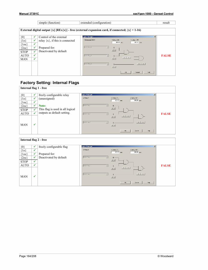
Manual 37391C easYgen-1000 - Genset Control
Page 164/208 © Woodward
simple (function) extended (configuration) result External digital output x] [RExx] - free (external expansion card, if connected; x = 1-16) 0 Control of the external
relay x, if this is connected Prepared for: Deactivated by default
FALSE
1o 1oc 2oc STOP AUTO MAN
Factory Setting: Internal Flags Internal flag 1 - free 0 freely configurable relay
(unassigned) Note: This flag is used in all logical outputs as default setting.
FALSE
1o 1oc 2oc STOP AUTO
MAN
Internal flag 2 - free 0 freely configurable flag
Prepared for: Deactivated by default
FALSE
1o 1oc 2oc STOP AUTO
MAN

Manual 37391C easYgen-1000 - Genset Control
© Woodward Page 165/208
simple (function) extended (configuration) result Internal flag 3 - free 0 freely configurable flag
Prepared for: Deactivated by default
FALSE
1o 1oc 2oc STOP AUTO
MAN
Internal flag 4 - free 0 freely configurable flag
Prepared for: Deactivated by default
FALSE
1o 1oc 2oc STOP AUTO
MAN
Internal flag 5 - free 0 freely configurable flag
Prepared for: Deactivated by default
FALSE
1o 1oc 2oc STOP AUTO
MAN

Manual 37391C easYgen-1000 - Genset Control
Page 166/208 © Woodward
simple (function) extended (configuration) result Internal flag 6 - free 0 freely configurable flag
Prepared for: Deactivated by default
FALSE
1o 1oc 2oc STOP AUTO
MAN
Internal flag 7 - extend emergency power operation 0 freely configurable flag
Prepared for: Deactivated by default
dependent on Logics
Command Variables
[04.08] and [04.07] and
[02.11]
1o 1oc 2oc STOP AUTO
MAN
Internal flag 8 - engine start via timer 0 Prepared for:
TRUE once the configured time 1 has been reached [11.01], and the configured time 2 [11.02] has not been reached as well if the current day is the configured day [11.03] (see page 124 "LogicsManager: Timer")
dependent on timer
1o 1oc 2oc STOP --- AUTO
MAN ---
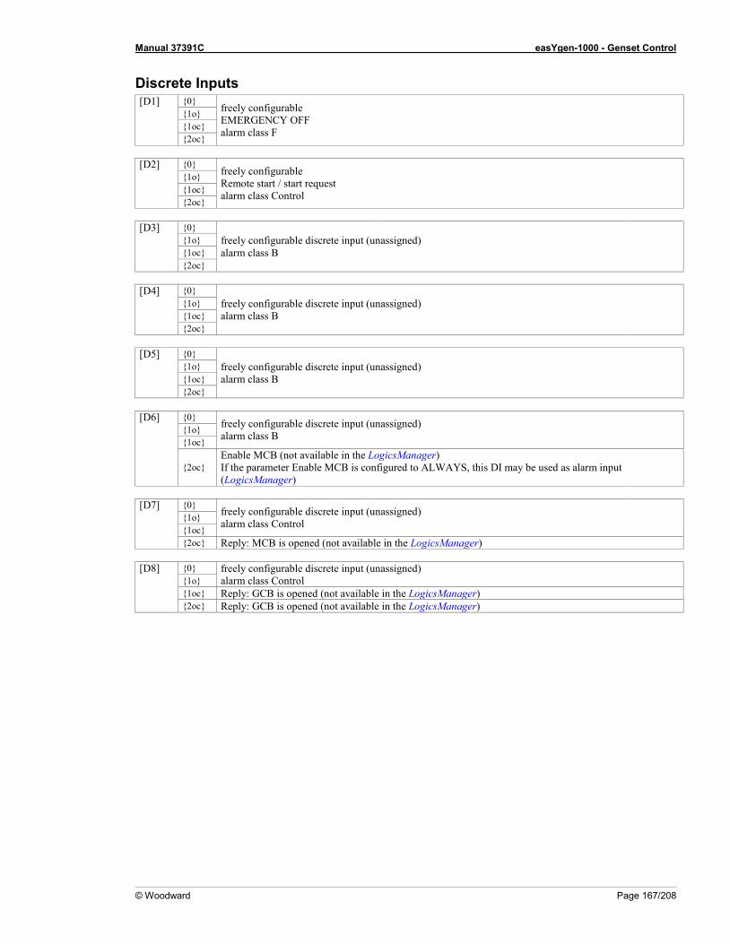
Manual 37391C easYgen-1000 - Genset Control
© Woodward Page 167/208
Discrete Inputs [D1] 0
freely configurable EMERGENCY OFF alarm class F
1o 1oc 2oc [D2] 0
freely configurable Remote start / start request alarm class Control
1o 1oc 2oc [D3] 0
freely configurable discrete input (unassigned) alarm class B
1o 1oc 2oc [D4] 0
freely configurable discrete input (unassigned) alarm class B
1o 1oc 2oc [D5] 0
freely configurable discrete input (unassigned) alarm class B
1o 1oc 2oc [D6] 0 freely configurable discrete input (unassigned)
alarm class B 1o 1oc
2oc Enable MCB (not available in the LogicsManager) If the parameter Enable MCB is configured to ALWAYS, this DI may be used as alarm input (LogicsManager)
[D7] 0 freely configurable discrete input (unassigned)
alarm class Control 1o 1oc 2oc Reply: MCB is opened (not available in the LogicsManager) [D8] 0 freely configurable discrete input (unassigned)
alarm class Control 1o 1oc Reply: GCB is opened (not available in the LogicsManager) 2oc Reply: GCB is opened (not available in the LogicsManager)

Manual 37391C easYgen-1000 - Genset Control
Page 168/208 © Woodward
Appendix C. Characteristics Of The VDO Inputs
VDO Input "Pressure" (0 to 5 bar / 0 to 72 psi) - Index "III" ≡≡≡≡≡≡≡≡≡≡≡≡≡≡≡≡≡≡≡≡≡≡≡≡≡
Since VDO sensors are available in various different types, the Index Numbers of the characteristic curve tables are listed. The customer must observe to order a sensor with the correct characteristic curve when selecting a VDO sensor. Manufacturers of VDO sensors usually list these tables in their catalogs.
VDO-Eingang 0-5 bar / 0-72 psi
0
1
2
3
4
5
6
0 20 40 60 80 100 120 140 160 180 200
Ohm
bar
-10
0
10
20
30
40
50
60
70
80 psi VDO Input
0-5 bar / 0-72 psi
psi
bar
Figure 3-34: Analog inputs - characteristics diagram VDO 0 to 5 bar, Index "III"
Ohm bar psi Ohm bar psi Ohm bar psi
10 0.00 0.00 15 0.13 1.81 20 0.25 3.63 25 0.38 5.44 30 0.50 7.25 35 0.64 9.27 40 0.78 11.28 45 0.92 13.30 50 1.06 15.36 55 1.21 17.49 60 1.35 19.62 65 1.50 21.76
70 1.65 23.89 75 1.79 26.02 80 1.94 28.15 85 2.09 30.29 90 2.24 32.42 95 2.38 34.55
100 2.53 36.69 105 2.68 38.82 110 2.82 40.95 115 2.97 43.09 120 3.11 45.12 125 3.25 47.14
130 3.39 49.15 135 3.53 51.19 140 3.68 53.32 145 3.82 55.46 150 3.97 57.59 155 4.12 59.72 160 4.26 61.86 165 4.41 63.99 170 4.56 66.17 175 4.72 68.44 180 4.88 70.71 185 5.03 72.97

Manual 37391C easYgen-1000 - Genset Control
© Woodward Page 169/208
VDO Input "Pressure" (0 to 10 bar / 0 to 145 psi) - Index "IV" ≡≡≡≡≡≡≡≡≡≡≡≡≡≡≡≡≡≡≡≡≡≡≡≡≡
VDO-Eingang 0-10 bar / 0-145 psi
0
2
4
6
8
10
12
0 20 40 60 80 100 120 140 160 180 200
Ohm
bar
-20
0
20
40
60
80
100
120
140
160 psi VDO Input
0-10 bar / 0-145 psi
psi
bar
Figure 3-35: Analog inputs - characteristics diagram VDO 0 to 10 bar, Index "IV"
Ohm bar psi Ohm bar psi Ohm bar psi
10 0.00 0.00 15 0.24 3.45 20 0.48 6.91 25 0.71 10.36 30 0.95 13.81 35 1.19 17.27 40 1.43 20.72 45 1.67 24.17 50 1.90 27.63 55 2.16 31.30 60 2.42 35.11 65 2.68 38.93
70 2.95 42.75 75 3.24 46.92 80 3.53 51.19 85 3.82 55.46 90 4.11 59.63 95 4.39 63.66
100 4.67 67.69 105 4.94 71.71 110 5.22 75.74 115 5.50 79.77 120 5.78 83.80 125 6.06 87.93 130 6.38 92.46
135 6.69 97.00 140 7.00 101.53 145 7.33 106.36 150 7.67 111.20 155 8.00 116.03 160 8.33 120.87 165 8.67 125.70 170 9.00 130.54 175 9.36 135.72 180 9.71 140.90 185 10.07 146.08

Manual 37391C easYgen-1000 - Genset Control
Page 170/208 © Woodward
VDO Input "Temperature" (40 to 120 °C / 104 to 248 °F) - Index "92-027-004"
≡≡≡≡≡≡≡≡≡≡≡≡≡≡≡≡≡≡≡≡≡≡≡≡≡
VDO-Eingang 40-120 °C / 104-248 °F
0
20
40
60
80
100
120
140
160
0 50 100 150 200 250 300 350
Ohm
°C
0
50
100
150
200
250
300 °F VDO Input
40-120 °C / 104-248 °F
°C
°F
Figure 3-36: Analog inputs - characteristics diagram VDO 40 to 120 °C, Index "92-027-004"
Ohm °C °F Ohm °C °F Ohm °C °F
20 124 255 30 109 229 40 99 210 50 91 196 60 85 185 70 80 175 80 76 168 90 72 162
100 69 156
110 66 151 120 64 146 130 61 142 140 59 138 150 57 135 160 56 132 170 54 129 180 52 126 190 51 123 200 50 121
210 48 119 220 47 117 230 46 115 240 45 113 250 44 111 260 43 109 270 42 107
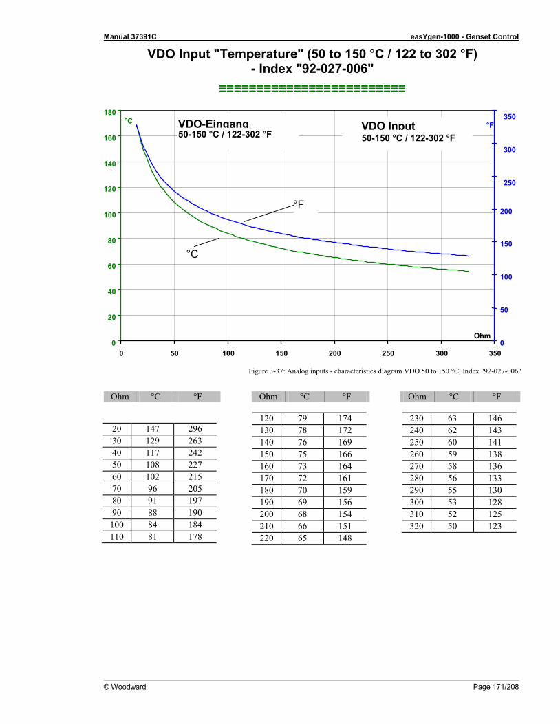
Manual 37391C easYgen-1000 - Genset Control
© Woodward Page 171/208
VDO Input "Temperature" (50 to 150 °C / 122 to 302 °F) - Index "92-027-006"
≡≡≡≡≡≡≡≡≡≡≡≡≡≡≡≡≡≡≡≡≡≡≡≡≡
VDO-Eingang 50-150 °C / 122-302 °F
0
20
40
60
80
100
120
140
160
180
0 50 100 150 200 250 300 350 Ohm
°C
0
50
100
150
200
250
300
350 °F VDO Input
50-150 °C / 122-302 °F
°C
°F
Figure 3-37: Analog inputs - characteristics diagram VDO 50 to 150 °C, Index "92-027-006"
Ohm °C °F Ohm °C °F Ohm °C °F
20 147 296 30 129 263 40 117 242 50 108 227 60 102 215 70 96 205 80 91 197 90 88 190
100 84 184 110 81 178
120 79 174 130 78 172 140 76 169 150 75 166 160 73 164 170 72 161 180 70 159 190 69 156 200 68 154 210 66 151 220 65 148
230 63 146 240 62 143 250 60 141 260 59 138 270 58 136 280 56 133 290 55 130 300 53 128 310 52 125 320 50 123

Manual 37391C easYgen-1000 - Genset Control
Page 172/208 © Woodward
SMP Input "Temperature" (25 to 150 °C / 77 to 302 °F)
≡≡≡≡≡≡≡≡≡≡≡≡≡≡≡≡≡≡≡≡≡≡≡≡≡
Figure 3-38: Analog inputs - characteristics diagram SMP TH2125
Temp. [°C] 25 30 35 40 45 50 55 60 65 70 75 80 85 Temp. [°F 77 86 95 104 113 122 131 140 149 158 167 176 185 R [Ohm] 500.0 408.5 335.9 278.0 231.4 193.8 163.1 138.0 117.3 100.3 86.0 74.2 64.2
Temp. [°C] 90 95 100 105 110 115 120 125 130 135 140 145 150 Temp. [°F 194 203 212 221 257 239 248 257 266 275 284 293 302 R [Ohm] 55.8 48.7 42.6 37.4 33.0 29.2 25.9 23.0 20.6 18.4 16.5 14.9 13.4
Table 3-27: Analog inputs - characteristics diagram SMP TH2125

Manual 37391C easYgen-1000 - Genset Control
© Woodward Page 173/208
Appendix D. GetEventLog
The event history is a 300-entry FIFO (First In/First Out) memory for logging alarm events and operation states of the unit. Refer to the Event History section on page 18 for more info about the event history. It is possible to read out the event history using the direct configuration cable DPC and the GetEventLog software tool.
GetEventLog Software ≡≡≡≡≡≡≡≡≡≡≡≡≡≡≡≡≡≡≡≡≡≡≡≡≡
Installing GetEventLog GetEventLog can either be used as a stand alone or within LeoPC1. In order to call it up from LeoPC1, it must be installed into the LeoPC1 installation path. To install GetEventLog, start GetEventLog_vxxxxx.exe from the GetEventLog directory on the CD delivered with the unit. If you want to use GetEventLog from inside LeoPC1, it must be installed into the LeoPC1 installation directory.
Starting GetEventLog Connect the easYgen to a free COM port on your computer using the DPC as described under Configuration Using The PC on page 12. Start GetEventLog directly or call it up by selecting GetEventLog from the menu Tools in LeoPC1. After starting GetEventLog for the first time, you must configure the communication settings. To do this, select the Interface tab, configure the COM port according to the port, to which you have connected the DPC, and enter the other settings as represented in figure Figure 3-39 since these are the default settings of the easYgen-1000.
Figure 3-39: GetEventLog - interface configuration

Manual 37391C easYgen-1000 - Genset Control
Page 174/208 © Woodward
Reading Out GetEventLog On the Eventlog tab of GetEventLog, click the Request Eventlog button to read out the content of the event history memory. The content of the event history is displayed as shown in Figure 3-40.
Figure 3-40: GetEventLog - event history content
The 300 latest events are displayed in chronological order and each entry is composed like this:
"sign";"event date and time";"event no.";"event text" whereas the "sign" "+" indicates the occurrence and "-" indicates the disappearance or acknowledgement of
the alarm or state "event date and time" serves as a timestamp and indicates the date and time of the event
occurred "event no." indicates the event ID number that occurred "event text" indicates the event that occurred in clear text The event text is read out in the language, which is selected in the easYgen, like English or French. Some languages may not be supported by GetEventLog, like Japanese or Chinese. Then you may change the language in the unit. The event numbers are indicated in Table 3-28 at the end of this section. Please note that some event texts may be configured freely (like analog inputs, etc.) and may not correspond with the original text. The event numbers are unambiguous. Example: The entry "+";"2005-June-15 13:23:05.69";"014705";"Emergency run" means that an emergency run operation "014705" occurred "+" at June 15, 2005 at 23 minutes, 5 seconds and 69 hundredths of a second after 1 o'clock in the afternoon "2005-June-15 13:23:05.69".
Storing Event History Data Using the Save Eventlog button on the Eventlog tab, you are able to save the content of the event history in CSV format (comma separated values). You may open the saved file within Excel for example.
Figure 3-41: GetEventLog - event history content in Excel

Manual 37391C easYgen-1000 - Genset Control
© Woodward Page 175/208
Resetting the Event History
NOTE Be sure to be in the appropriate code level to reset the event history. If you have not entered the correct password for the required code level, the parameters for resetting the event history are not available (refer to the Event History section on page 18 for more information).
The event history can be reset using the parameter "Clear event log" via the front panel or LeoPC1 (deleted events or empty entries are represented with a series of dashes in the event history). To do this, perform the following steps:
Resetting the Event History Using the Front Panel Make sure that you are in code level CS3 (refer to the Password section on page 17). Set the parameter "Clear event log" to YES (refer to the Event History section on page 18). The complete event history is now being cleared (single events may be cleared by pressing the button).
Resetting the Event History Using LeoPC1 Connect the easYgen with your PC and start LeoPC1 as described in Configuration Using The PC on page 12. Set the parameter "Clear event log" to YES (refer to the Event History section on page 18). The complete event history is now being cleared.
Event Texts and Numbers
Event no. Event text Description 001912 Gen.overfreq. 1 Generator frequency has exceeded threshold 1 001913 Gen.overfreq. 2 Generator frequency has exceeded threshold 2 001962 Gen.underfreq. 1 Generator frequency has fallen below threshold 1 001963 Gen.Unterfreq. 2 Generator frequency has fallen below threshold 2 002012 Gen.overvolt. 1 Generator voltage has exceeded threshold 1 002013 Gen.overvolt. 2 Generator voltage has exceeded threshold 2 002062 Gen.undervolt. 1 Generator voltage has fallen below threshold 1 002063 Gen.undervolt. 2 Generator voltage has fallen below threshold 2 002112 Overspeed 1 Engine speed has exceeded threshold 1 002113 Overspeed 2 Engine speed has exceeded threshold 2 002162 Underspeed 1 Engine speed has fallen below threshold 1 002163 Underspeed 2 Engine speed has fallen below threshold 2 002218 Gen. overcurr. 1 Generator current has exceeded threshold 1 002219 Gen. overcurr. 2 Generator current has exceeded threshold 2 002220 Gen. overcurr. 3 Generator current has exceeded threshold 3 002262 Gen. Rv/Rd pow.1 Generator reverse/reduced power has exceeded threshold 1 002263 Gen. Rv/Rd pow.2 Generator reverse/reduced power has exceeded threshold 2 002312 Gen. Overload 1 Generator overload has exceeded threshold 1 002313 Gen. Overload 2 Generator overload has exceeded threshold 2 002412 Unbal. load 1 Generator load imbalance has exceeded threshold 1 002413 Unbal. load 2 Generator load imbalance has exceeded threshold 2 002457 Speed det. alarm Engine speed and generator frequency difference is exceeded 002504 Shutdwn malfunct. Engine could not be stopped within the configured time 002560 Mainten. days exceeded Maintenance days counter has expired 002561 Mainten. hours exceeded Maintenance hours counter has expired 002603 GCB fail to close GCB could not be closed within the configured attempts 002604 GCB fail to open GCB could not be opened within the configured time 002623 MCB fail to close MCB could not be closed within the configured attempts 002624 MCB fail to open MCB could not be opened within the configured time 002644 Timeout dead bus op. Dead bus operation has exceeded the delay 002652 Unintended stop Engine has stopped without intention 003263 Ground fault 1 Generator ground fault current has exceeded threshold 1 003264 Ground fault 2 Generator ground fault current has exceeded threshold 2 003325 Start fail Engine could not be started within the configured attempts 003907 Gen. asymmetry Generator voltage asymmetry has exceeded threshold 003955 Gen. phase rot. misw. Generator voltage phase rotation is not as configured 003975 Mains phase rot. misw. Mains voltage phase rotation is not as configured 004038 Inv.time ov.curr. Generator current has exceeded threshold 010005 Batt.undervolt.1 Battery voltage has fallen below threshold 1 010006 Batt.undervolt.2 Battery voltage has fallen below threshold 2 010007 Batt.overvolt.1 Battery voltage has exceeded threshold 1

Manual 37391C easYgen-1000 - Genset Control
Page 176/208 © Woodward
Event no. Event text Description 010008 Batt.overvolt.2 Battery voltage has exceeded threshold 2 010010 Lv1: Analog inp.1 * Analog input 1 level 1 is exceeded/fallen below 010011 Lv2: Analog inp.1 * Analog input 1 level 2 is exceeded/fallen below 010012 Lv1: Analog inp.2 * Analog input 2 level 1 is exceeded/fallen below 010013 Lv2: Analog inp.2 * Analog input 2 level 2 is exceeded/fallen below 010014 Wb: Analog inp.1 * Wire break at analog input 1 010015 Wb: Analog inp.2 * Wire break at analog input 2 010016 CAN Open Fault No CANopen protocol message is received 010017 CAN-Fault J1939 No J1939 data is received from an ECU 010018 Flexible Limit 1 * Flexible limit 1 exceeded/fallen below 010019 Flexible Limit 2 * Flexible limit 2 exceeded/fallen below 010020 Flexible Limit 3 * Flexible limit 3 exceeded/fallen below 010021 Flexible Limit 4 * Flexible limit 4 exceeded/fallen below 010600 DI 1 Text * Discrete input 1 is enabled 010601 DI 2 Text * Discrete input 2 is enabled 010602 DI 3 Text * Discrete input 3 is enabled 010603 DI 4 Text * Discrete input 4 is enabled 010604 DI 5 Text * Discrete input 5 is enabled 010605 DI 6 Text * Discrete input 6 is enabled 010607 DI 7 Text * Discrete input 7 is enabled 010608 DI 8 Text * Discrete input 8 is enabled 010802 Red stop lamp ECU has sent a red stop lamp signal to the control 010803 Amber warning lamp ECU has sent an amber warning lamp signal to the control 014353 Auto mode Automatic mode is active 014354 Stop mode Stop mode is active 014355 Manual mode Manual mode is active 014700 MCB open Status: MCB is open 014701 MCB close Status: MCB is closed 014702 GCB open Status: GCB is open 014703 GCB close Status: GCB is closed 014704 Mains failure Mains failure has been detected 014705 Emergency run Emergency power operation is active 014706 Engine is running Engine is running 014707 Critical mode Critical mode operation is active 016360 Ext. DI 1 text * External discrete input 1 is enabled 016361 Ext. DI 2 text * External discrete input 2 is enabled 016362 Ext. DI 3 text * External discrete input 3 is enabled 016364 Ext. DI 4 text * External discrete input 4 is enabled 016365 Ext. DI 5 text * External discrete input 5 is enabled 016366 Ext. DI 6 text * External discrete input 6 is enabled 016367 Ext. DI 7 text * External discrete input 7 is enabled 016368 Ext. DI 8 text * External discrete input 8 is enabled 016369 Ext. DI 9 text * External discrete input 9 is enabled 016370 Ext. DI 10 text * External discrete input 10 is enabled 016371 Ext. DI 11 text * External discrete input 11 is enabled 016372 Ext. DI 12 text * External discrete input 12 is enabled 016373 Ext. DI 13 text * External discrete input 13 is enabled 016374 Ext. DI 14 text * External discrete input 14 is enabled 016375 Ext. DI 15 text * External discrete input 15 is enabled 016376 Ext. DI 16 text * External discrete input 16 is enabled
* This is the default text, but may be configured freely Table 3-28: Event history - event texts and numbers

Manual 37391C easYgen-1000 - Genset Control
© Woodward Page 177/208
Appendix E. Average Generator Current Calculation
Calculating Principle ≡≡≡≡≡≡≡≡≡≡≡≡≡≡≡≡≡≡≡≡≡≡≡≡≡
The calculating principle of the average generator current depends on the setting of the parameter "Generator voltage measuring" (Parameter 6).
Generator Voltage Measuring Configured to "1Ph 2W"
Figure 3-42: Average generator current calculating principle - 1Ph 2W
The calculated average generator current is the current of phase L1. Formula: IGenAvg = IL1
Generator Voltage Measuring Configured to "1Ph 3W"
Figure 3-43: Average generator current calculating principle - 1Ph 3W
The calculated average generator current is the average of the currents of phase L1 and L3. Formula: IGenAvg = ( IL1 + IL3 ) / 2
Detail: Connection of the transducersL..
..
L....
G
67
85 Ge
nerat
or cu
rrent
(phas
e curr
ent)
../x A
../x A
../x A
../x Ax = 1 or 5
GL1 (A)L2 (B)L3 (C)
N
24 26 28 22
L3 L2 L1 NGenerator voltage 1Ph 2W
120 V
Phase25 27 29 23 480 V
X2 X1
x1x2
x1 (k)x2 (l)
Note:Connect the common
wires of the transducer near the unit.
x1 (k) - L3 (C)x1 (k) - L2 (B)x1 (k) - L1 (A)x2 (l)
Detail: Connection of the transducersL..
..
L....
G
67
85 Ge
nerat
or cu
rrent
(phas
e curr
ent)
../x A
../x A
../x A
../x Ax = 1 or 5
GL1 (A)L2 (B)L3 (C)
N
24 26 28 22
L3 L2 L1 NGenerator voltage 1Ph 3W
120 V
Phase25 27 29 23 480 V
X2 X1
x1x2
x1 (k)x2 (l)
Note:Connect the common
wires of the transducer near the unit.
x1 (k) - L3 (C)x1 (k) - L2 (B)x1 (k) - L1 (A)x2 (l)

Manual 37391C easYgen-1000 - Genset Control
Page 178/208 © Woodward
Generator Voltage Measuring Configured to "3Ph 3W" or "3Ph 4W" If "3Ph3W" or "3Ph4W" are configured for generator voltage measuring (Parameter 6), the calculating principle of the average generator current is dependent on the setting of the parameter "Generator current measuring" (Parameter 7).
Figure 3-44: Average generator current calculating principle - 3Ph 3W
Figure 3-45: Average generator current calculating principle - 3Ph 4W
Generator Current Measuring Configured to "L1 L2 L3" The calculated average generator current is calculated from the currents of all three available phases. Formula: IGenAvg = ( IL1 + IL2 + IL3 ) / 3
Generator Current Measuring Configured to "L1" The calculated average generator current is the current of phase L1. Formula: IGenAvg = IL1
Generator Current Measuring Configured to "L2" The calculated average generator current is the current of phase L2. Formula: IGenAvg = IL2
Generator Current Measuring Configured to "L3" The calculated average generator current is the current of phase L3. Formula: IGenAvg = IL3
Detail: Connection of the transducersL..
..
L....
G
67
85 Ge
nerat
or cu
rrent
(phas
e curr
ent)
../x A
../x A
../x A
../x Ax = 1 or 5
GL1 (A)L2 (B)L3 (C)
N
24 26 28 22
L3 L2 L1 NGenerator voltage 3Ph 3W
120 V
Phase25 27 29 23 480 V
X2 X1
x1x2
x1 (k)x2 (l)
Note:Connect the common
wires of the transducer near the unit.
x1 (k) - L3 (C)x1 (k) - L2 (B)x1 (k) - L1 (A)x2 (l)
Detail: Connection of the transducers
X2
x2L..
x1 (k)..
L..x2 (l)..
GX1
x1
67
85
x1 (k) - L1 (A)x2 (l)
x1 (k) - L3 (C)
L1 (A)L2 (B)L3 (C)
N
x1 (k) - L2 (B)
Gene
rator
curre
nt(ph
ase c
urren
t)
../x A
../x A
../x A
../x Ax = 1 or 5
Note:Connect the common
wires of the transducer near the unit.
G
24 26 28 22
L3 L2 L1 NGenerator voltage 3Ph 4W
120 V
Phase25 27 29 23 480 V
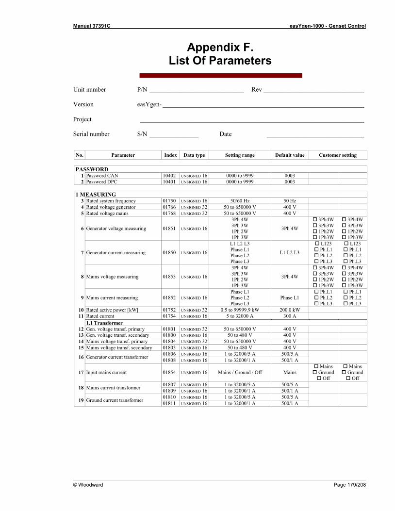
Manual 37391C easYgen-1000 - Genset Control
© Woodward Page 179/208
Appendix F. List Of Parameters
Unit number P/N _____________________________ Rev _______________________________ Version easYgen- ______________________________________________________________ Project _____________________________________________________________________ Serial number S/N _______________ Date ______________________________
No. Parameter Index Data type Setting range Default value Customer setting
PASSWORD 1 Password CAN 10402 UNSIGNED 16 0000 to 9999 0003 2 Password DPC 10401 UNSIGNED 16 0000 to 9999 0003
1 MEASURING
3 Rated system frequency 01750 UNSIGNED 16 50/60 Hz 50 Hz 4 Rated voltage generator 01766 UNSIGNED 32 50 to 650000 V 400 V 5 Rated voltage mains 01768 UNSIGNED 32 50 to 650000 V 400 V
6 Generator voltage measuring 01851 UNSIGNED 16
3Ph 4W 3Ph 3W 1Ph 2W 1Ph 3W
3Ph 4W
3Ph4W 3Ph3W 1Ph2W 1Ph3W
3Ph4W 3Ph3W 1Ph2W 1Ph3W
7 Generator current measuring 01850 UNSIGNED 16
L1 L2 L3 Phase L1 Phase L2 Phase L3
L1 L2 L3
L123 Ph.L1 Ph.L2 Ph.L3
L123 Ph.L1 Ph.L2 Ph.L3
8 Mains voltage measuring 01853 UNSIGNED 16
3Ph 4W 3Ph 3W 1Ph 2W 1Ph 3W
3Ph 4W
3Ph4W 3Ph3W 1Ph2W 1Ph3W
3Ph4W 3Ph3W 1Ph2W 1Ph3W
9 Mains current measuring 01852 UNSIGNED 16 Phase L1 Phase L2 Phase L3
Phase L1 Ph.L1 Ph.L2 Ph.L3
Ph.L1 Ph.L2 Ph.L3
10 Rated active power [kW] 01752 UNSIGNED 32 0.5 to 99999.9 kW 200.0 kW 11 Rated current 01754 UNSIGNED 16 5 to 32000 A 300 A
1.1 Transformer 12 Gen. voltage transf. primary 01801 UNSIGNED 32 50 to 650000 V 400 V 13 Gen. voltage transf. secondary 01800 UNSIGNED 16 50 to 480 V 400 V 14 Mains voltage transf. primary 01804 UNSIGNED 32 50 to 650000 V 400 V 15 Mains voltage transf. secondary 01803 UNSIGNED 16 50 to 480 V 400 V
16 Generator current transformer 01806 UNSIGNED 16 1 to 32000/5 A 500/5 A 01808 UNSIGNED 16 1 to 32000/1 A 500/1 A
17 Input mains current 01854 UNSIGNED 16 Mains / Ground / Off Mains Mains Ground Off
Mains Ground Off
18 Mains current transformer 01807 UNSIGNED 16 1 to 32000/5 A 500/5 A 01809 UNSIGNED 16 1 to 32000/1 A 500/1 A
19 Ground current transformer 01810 UNSIGNED 16 1 to 32000/5 A 500/5 A 01811 UNSIGNED 16 1 to 32000/1 A 500/1 A

Manual 37391C easYgen-1000 - Genset Control
Page 180/208 © Woodward
No. Parameter Index Data type Setting range Default value Customer setting
2 APPLICATION
20 Application mode 3401 UNSIGNED 16
None 0 GCB open 1o
GCB 1oc GCB/MCB 2oc
GCB/MCB 2oc
0 1o 1oc 2oc
0 1o 1oc 2oc
21 Start req. in Auto 12120 Logman refer to LogicsManager chapter on page 157; default: (09.02. + 0) + 0 22 Stop req. in Auto 12190 Logman refer to LogicsManager chapter on page 157; default: (0 & 1) & 1 23 Start w/o load 10718 Logman refer to LogicsManager chapter on page 157; default: (0 & 1) & !00.13
24 Startup in mode 1795 UNSIGNED 16
Stop Auto
Manual last
Stop
STOP AUTO MAN last
STOP AUTO MAN last
25 Operation mode AUTO 12510 Logman refer to LogicsManager chapter on page 157; default: (0 & 1) & 1 26 Operation mode MAN 12520 Logman refer to LogicsManager chapter on page 157; default: (0 & 1) & 1 27 Operation mode STOP 12530 Logman refer to LogicsManager chapter on page 157; default: (0 & 1) & 1 28 Alternative screen 4104 UNSIGNED 16 YES/NO NO Y N Y N 29 Show mains data 4106 UNSIGNED 16 YES/NO YES Y N Y N 30 Value display field 1 4300 UNSIGNED 16 refer to Parameter 30 Gen. frq 31 Unit display field 1 4305 UNSIGNED 16 refer to Parameter 31 OFF 30 Value display field 2 4301 UNSIGNED 16 refer to Parameter 30 Gen. Pwr. 31 Unit display field 2 4306 UNSIGNED 16 refer to Parameter 31 OFF 30 Value display field 3 4302 UNSIGNED 16 refer to Parameter 30 Gen Cur A 31 Unit display field 3 4307 UNSIGNED 16 refer to Parameter 31 OFF 30 Value display field 4 4303 UNSIGNED 16 refer to Parameter 30 Gen Cur B 31 Unit display field 4 4308 UNSIGNED 16 refer to Parameter 31 OFF 30 Value display field 5 4304 UNSIGNED 16 refer to Parameter 30 Gen Cur C 31 Unit display field 5 4309 UNSIGNED 16 refer to Parameter 31 OFF
2.1 Critical Mode 32 Critical mode 12220 Logman refer to LogicsManager chap. on page 157; default: (0 & !05.08) & !09.01 33 Critical mode postrun 4109 UNSIGNED 16 0 to 6000 s 600 s 34 close GCB in override 4100 UNSIGNED 16 YES/NO NO Y N Y N 35 Override alarmcl. also in MAN 4105 UNSIGNED 16 YES/NO NO Y N Y N 36 Break emergency in override 4101 UNSIGNED 16 0 to 999 s 5 s
Manual 37391C easYgen-1000 - Genset Control
© Woodward Page 181/208
No. Parameter Index Data type Setting range Default value Customer setting
3 CONFIGURE ENGINE
37 Start/stop mode 3321 UNSIGNED 16 Diesel Gas
External Diesel
Diesel Gas
External
Diesel Gas
External 3.1 Engine type: Diesel
38 Fuel relay: close to stop 3320 UNSIGNED 16 YES/NO NO Y N Y N 39 Preglow time 3308 UNSIGNED 16 0 to 300 s 3 s
40 Preglow mode 3317 UNSIGNED 16
NO Always
Analog input [T1] Analog input [T2]
NO
No Always [T1] [T2]
No Always [T1] [T2]
41 Preglow temp. threshold 3309 SIGNED 16 -10 to 140 °C 0 °C 3.2 Engine type: Gas
42 Ignition delay 3310 UNSIGNED 16 0 to 999 s 3 s 43 Gas valve delay 3311 UNSIGNED 16 0 to 999 s 3 s 44 Min. speed for ignition 3312 UNSIGNED 16 10 to 1800 RPM 100 RPM
3.3 Pickup 45 Speed Pickup 1600 UNSIGNED 16 ON/OFF ON 1 0 1 0 46 Nominal speed 1601 UNSIGNED 16 500 to 4000 RPM 1500 RPM 47 Pickup measurement from: 1604 UNSIGNED 16 Pickup / Sensor Pickup P S P S 48 Fly wheel teeth 1602 UNSIGNED 16 2 to 260 118 49 Pulses per revolution 1603 UNSIGNED 16 2.00 to 260.00 118.00 50 Filter time constant 10102 UNSIGNED 16 0 to 8 0
3.4 Start/stop automatic 51 Auxiliary services prerun 3300 UNSIGNED 16 0 to 999 s 0 s 52 Starter time 3306 UNSIGNED 16 1 to 99 s 5 s 53 Start pause time 3307 UNSIGNED 16 1 to 99 s 7 s 54 Cool down time 3316 UNSIGNED 16 1 to 999 s 20 s 55 Auxiliary services postrun 3301 UNSIGNED 16 0 to 999 s 0 s 56 Time of engine stop 3326 UNSIGNED 16 0 to 99 s 10 s 57 Firing speed 3313 UNSIGNED 16 5 to 60 Hz 15 Hz 58 Logicm. for firing speed 3324 UNSIGNED 16 YES/NO NO Y N Y N 59 Ignition speed 12500 Logman refer to LogicsManager chapter starting page 157; default: (0 & 1) & 1 60 Engine monit. delay time 3315 UNSIGNED 16 0 to 99 s 8 s
3.5 Idle Mode 61 Constant idle run 12550 Logman refer to LogicsManager chapter starting page 157; default: (0 & 1) & 1 62 Idle mode automatic 12570 Logman refer to LogicsManager chapter starting page 157; default: (0 & 1) & 1 63 Time for automatic idle run 3328 UNSIGNED 16 1 to 9999 s 10 s 64 During emerg/critical 3329 UNSIGNED 16 YES/NO NO Y N Y N
4 BREAKER
65 GCB open relay 3403 UNSIGNED 16 N.O. N.C. N.O. N.O.
N.C. N.O. N.C.
66 GCB time pulse 3416 UNSIGNED 16 0.04 to 10.00 s 0.24 s 67 GCB close pulse 3409 UNSIGNED 16 YES/NO NO Y N Y N 68 GCB auto unblock 3405 UNSIGNED 16 YES/NO NO Y N Y N 69 Undelayed close GCB 12210 Logman refer to LogicsManager chapter starting page 157; default: (04.09 & 1) & 1 70 GCB frequency window 3350 UNSIGNED 16 0.2 to 10.0 % 2.0 % 71 GCB voltage window 3351 UNSIGNED 16 1 to 100 % 10 % 72 CB settling time 3415 UNSIGNED 16 0 to 99 s 2 s 73 MCB auto unlock 3407 UNSIGNED 16 YES/NO NO Y N Y N 74 Close MCB in STOP mode 3410 UNSIGNED 16 YES/NO YES Y N Y N 75 MCB time pulse 3417 UNSIGNED 16 0.04 to 10.00 s 0.24 s 76 Enable MCB 3423 UNSIGNED 16 ALWAYS / via DI6 ALWAYS A DI6 A DI6 77 Transfer time GCB/MCB 3400 UNSIGNED 16 0.10 to 99.99 s 1.00 s
5 EMERGENCY POWER (AMF)
78 On/Off 2802 UNSIGNED 16 ON/OFF ON 1 0 1 0 79 Mains fail delay time 2800 UNSIGNED 16 0.20 to 99.99 s 3.00 s 80 Mains settling time 2801 UNSIGNED 16 1 to 9,999 s 20 s 81 Emerg. start with MCB failure 3408 UNSIGNED 16 YES/NO NO Y N Y N 82 Inhibit emergency run 12200 Logman refer to LogicsManager chapter starting page 157; default: (0 & 1) & 1

Manual 37391C easYgen-1000 - Genset Control
Page 182/208 © Woodward
No. Parameter Index Data type Setting range Default value Customer setting
6 MONITORING
83 Time until horn reset 1756 UNSIGNED 16 0 to 1,000 s 180 s
84 External acknowledge 12490 Logman refer to LogicsManager chapter starting page 157; default: (0 & !04.03) + 0
6.1 Monitoring Generator 85 Voltage monitoring generator 1770 UNSIGNED 16 3 phase/4 phase 3 phase 3 4 3 4
6.1.1 Generator: overfrequency level 1 86 Monitoring level 1 1900 UNSIGNED 16 ON/OFF ON 1 0 1 0 87 Limit level 1 1904 UNSIGNED 16 50.0 to 130.0 % 110.0 % 88 Delay level 1 1905 UNSIGNED 16 0.02 to 99.99 s 1.50 s 89 Alarm class level 1 1901 UNSIGNED 16 A/B/C/D/E/F B 90 Self acknowledge level 1 1902 UNSIGNED 16 YES/NO NO Y N Y N
6.1.2 Generator: overfrequency level 2 86 Monitoring level 2 1906 UNSIGNED 16 ON/OFF ON 1 0 1 0 87 Limit level 2 1910 UNSIGNED 16 50.0 to 130.0 % 115.0 % 88 Delay level 2 1911 UNSIGNED 16 0.02 to 99.99 s 0.30 s 89 Alarm class level 2 1907 UNSIGNED 16 A/B/C/D/E/F F 90 Self acknowledge level 2 1908 UNSIGNED 16 YES/NO NO Y N Y N
6.1.3 Generator: underfrequency level 1 91 Monitoring level 1 1950 UNSIGNED 16 ON/OFF ON 1 0 1 0 92 Limit level 1 1954 UNSIGNED 16 50.0 to 130.0 % 90.0 % 93 Delay level 1 1955 UNSIGNED 16 0.02 to 99.99 s 5.00 s 94 Alarm class level 1 1951 UNSIGNED 16 A/B/C/D/E/F B 95 Self acknowledge level 1 1952 UNSIGNED 16 YES/NO NO Y N Y N 96 Delayed by engine speed level 1 1953 UNSIGNED 16 YES/NO NO Y N Y N
6.1.4 Generator: underfrequency level 2 91 Monitoring level 2 1956 UNSIGNED 16 ON/OFF ON 1 0 1 0 92 Limit level 2 1960 UNSIGNED 16 50.0 to 130.0 % 84.0 % 93 Delay level 2 1961 UNSIGNED 16 0.02 to 99.99 s 0.30 s 94 Alarm class level 2 1957 UNSIGNED 16 A/B/C/D/E/F F 95 Self acknowledge level 2 1958 UNSIGNED 16 YES/NO NO Y N Y N 96 Delayed by engine speed level 2 1959 UNSIGNED 16 YES/NO NO Y N Y N

Manual 37391C easYgen-1000 - Genset Control
© Woodward Page 183/208
No. Parameter Index Data type Setting range Default value Customer setting
6 MONITORING
6.1.5 Generator: overvoltage level 1 97 Monitoring level 1 2000 UNSIGNED 16 ON/OFF ON 1 0 1 0 98 Limit level 1 2004 UNSIGNED 16 50.0 to 125.0 % 108.0 % 99 Delay level 1 2005 UNSIGNED 16 0.02 to 99.99 s 5.00 s
100 Alarm class level 1 2001 UNSIGNED 16 A/B/C/D/E/F B 101 Self acknowledge level 1 2002 UNSIGNED 16 YES/NO NO Y N Y N 102 Delayed by engine speed level 1 2003 UNSIGNED 16 YES/NO NO Y N Y N
6.1.6 Generator: overvoltage level 2 97 Monitoring level 2 2006 UNSIGNED 16 ON/OFF ON 1 0 1 0 98 Limit level 2 2010 UNSIGNED 16 50.0 to 125.0 % 112.0 % 99 Delay level 2 2011 UNSIGNED 16 0.02 to 99.99 s 0.30 s
100 Alarm class level 2 2007 UNSIGNED 16 A/B/C/D/E/F F 101 Self acknowledge level 2 2008 UNSIGNED 16 YES/NO NO Y N Y N 102 Delayed by engine speed level 2 2009 UNSIGNED 16 YES/NO NO Y N Y N
6.1.7 Generator: undervoltage level 1 103 Monitoring level 1 2050 UNSIGNED 16 ON/OFF ON 1 0 1 0 104 Limit level 1 2054 UNSIGNED 16 50.0 to 125.0 % 92.0 % 105 Delay level 1 2055 UNSIGNED 16 0.02 to 99.99 s 5.00 s 106 Alarm class level 1 2051 UNSIGNED 16 A/B/C/D/E/F B 107 Self acknowledge level 1 2052 UNSIGNED 16 YES/NO NO Y N Y N 108 Delayed by engine speed level 1 2053 UNSIGNED 16 YES/NO YES Y N Y N
6.1.8 Generator: undervoltage level 2 103 Monitoring level 2 2056 UNSIGNED 16 ON/OFF ON 1 0 1 0 104 Limit level 2 2060 UNSIGNED 16 50.0 to 125.0 % 88.0 % 105 Delay level 2 2061 UNSIGNED 16 0.02 to 99.99 s 0.30 s 106 Alarm class level 2 2057 UNSIGNED 16 A/B/C/D/E/F F 107 Self acknowledge level 2 2058 UNSIGNED 16 YES/NO NO Y N Y N 108 Delayed by engine speed level 2 2059 UNSIGNED 16 YES/NO YES Y N Y N
6.1.9 Generator: overcurrent level 1 109 Monitoring level 1 2200 UNSIGNED 16 ON/OFF ON 1 0 1 0 110 Limit level 1 2204 UNSIGNED 16 50.0 to 300.0 % 110.0 % 111 Delay level 1 2205 UNSIGNED 16 0.02 to 99.99 s 30.00 s 112 Alarm class level 1 2201 UNSIGNED 16 A/B/C/D/E/F E 113 Self acknowledge level 1 2202 UNSIGNED 16 YES/NO NO Y N Y N
6.1.10 Generator: overcurrent level 2 109 Monitoring level 2 2206 UNSIGNED 16 ON/OFF ON 1 0 1 0 110 Limit level 2 2210 UNSIGNED 16 50.0 to 300.0 % 150.0 % 111 Delay level 2 2211 UNSIGNED 16 0.02 to 99.99 s 1.00 s 112 Alarm class level 2 2207 UNSIGNED 16 A/B/C/D/E/F F 113 Self acknowledge level 2 2208 UNSIGNED 16 YES/NO NO Y N Y N
6.1.11 Generator: overcurrent level 3 109 Monitoring level 3 2212 UNSIGNED 16 ON/OFF ON 1 0 1 0 110 Limit level 3 2216 UNSIGNED 16 50.0 to 300.0 % 250.0 % 111 Delay level 3 2217 UNSIGNED 16 0.02 to 99.99 s 0.40 s 112 Alarm class level 3 2213 UNSIGNED 16 A/B/C/D/E/F F 113 Self acknowledge level 3 2214 UNSIGNED 16 YES/NO NO Y N Y N
6.1.12 Gen.: reverse/reduced pow. level 1 114 Monitoring level 1 2250 UNSIGNED 16 ON/OFF ON 1 0 1 0 115 Limit level 1 2254 INTEGER 16 -99.9 to 99.9 % -3.0 % 116 Delay level 1 2255 UNSIGNED 16 0.02 to 99.99 s 5.00 s 117 Alarm class level 1 2251 UNSIGNED 16 A/B/C/D/E/F B 118 Self acknowledge level 1 2252 UNSIGNED 16 YES/NO NO Y N Y N 119 Delayed by engine speed level 1 2253 UNSIGNED 16 YES/NO NO Y N Y N
6.1.13 Gen.: reverse/reduced pow. level 2 114 Monitoring level 2 2256 UNSIGNED 16 ON/OFF ON 1 0 1 0 115 Limit level 2 2260 U INTEGER 16 -99.9 to 99.9 % -5.0 % 116 Delay level 2 2261 UNSIGNED 16 0.02 to 99.99 s 3.00 s 117 Alarm class level 2 2257 UNSIGNED 16 A/B/C/D/E/F E 118 Self acknowledge level 2 2258 UNSIGNED 16 YES/NO NO Y N Y N 119 Delayed by engine speed level 2 2259 UNSIGNED 16 YES/NO NO Y N Y N

Manual 37391C easYgen-1000 - Genset Control
Page 184/208 © Woodward
No. Parameter Index Data type Setting range Default value Customer setting
6 MONITORING
6.1.14 Generator: overload level 1 120 Monitoring level 1 2300 UNSIGNED 16 ON/OFF ON 1 0 1 0 121 Limit level 1 2304 UNSIGNED 16 50.0 to 300.0 % 110.0 % 122 Delay level 1 2305 UNSIGNED 16 0.02 to 99.99 s 11.00 s 123 Alarm class level 1 2301 UNSIGNED 16 A/B/C/D/E/F B 124 Self acknowledge level 1 2302 UNSIGNED 16 YES/NO NO Y N Y N
6.1.15 Generator: overload level 2 120 Monitoring level 2 2306 UNSIGNED 16 ON/OFF ON 1 0 1 0 121 Limit level 2 2310 UNSIGNED 16 50.0 to 300.0 % 120.0 % 122 Delay level 2 2311 UNSIGNED 16 0.02 to 99.99 s 0.10 s 123 Alarm class level 2 2307 UNSIGNED 16 A/B/C/D/E/F E 124 Self acknowledge level 2 2308 UNSIGNED 16 YES/NO NO Y N Y N
6.1.16 Generator: unbalanced load level 1 125 Monitoring level 1 2400 UNSIGNED 16 ON/OFF ON 1 0 1 0 126 Limit level 1 2404 UNSIGNED 16 0.0 to 100.0 % 10.0 % 127 Delay level 1 2405 UNSIGNED 16 0.02 to 99.99 s 10.00 s 128 Alarm class level 1 2401 UNSIGNED 16 A/B/C/D/E/F B 129 Self acknowledge level 1 2402 UNSIGNED 16 YES/NO NO Y N Y N 130 Delayed by engine speed level 1 2403 UNSIGNED 16 YES/NO NO Y N Y N
6.1.17 Generator: unbalanced load level 2 125 Monitoring level 2 2406 UNSIGNED 16 ON/OFF ON 1 0 1 0 126 Limit level 2 2410 UNSIGNED 16 0.0 to 100.0 % 15.0 % 127 Delay level 2 2411 UNSIGNED 16 0.02 to 99.99 s 1.00 s 128 Alarm class level 2 2407 UNSIGNED 16 A/B/C/D/E/F E 129 Self acknowledge level 2 2408 UNSIGNED 16 YES/NO NO Y N Y N 130 Delayed by engine speed level 2 2409 UNSIGNED 16 YES/NO NO Y N Y N
6.1.18 Generator: voltage asymmetry 131 Monitoring 3900 UNSIGNED 16 ON/OFF ON 1 0 1 0 132 Limit 3903 UNSIGNED 16 0.5 to 99.9 % 10.0 % 133 Delay 3904 UNSIGNED 16 0.02 to 99.99 s 5.00 s 134 Alarm class 3901 UNSIGNED 16 A/B/C/D/E/F F 135 Self acknowledge 3902 UNSIGNED 16 YES/NO NO Y N Y N 136 Delayed by engine speed 3905 UNSIGNED 16 YES/NO YES Y N Y N
6.1.19 Generator: ground fault level 1 137 Monitoring level 1 3250 UNSIGNED 16 ON/OFF OFF 1 0 1 0 138 Limit level 1 3254 UNSIGNED 16 0 to 300 % 10 % 139 Delay level 1 3255 UNSIGNED 16 0.02 to 99.99 s 0.20 s 140 Alarm class level 1 3251 UNSIGNED 16 A/B/C/D/E/F B 141 Self acknowledge level 1 3252 UNSIGNED 16 YES/NO NO Y N Y N 142 Delayed by engine speed level 1 3253 UNSIGNED 16 YES/NO NO Y N Y N
6.1.20 Generator: ground fault level 2 137 Monitoring level 2 3256 UNSIGNED 16 ON/OFF OFF 1 0 1 0 138 Limit level 2 3260 UNSIGNED 16 0 to 300 % 30 % 139 Delay level 2 3261 UNSIGNED 16 0.02 to 99.99 s 0.10 s 140 Alarm class level 2 3257 UNSIGNED 16 A/B/C/D/E/F F 141 Self acknowledge level 2 3258 UNSIGNED 16 YES/NO NO Y N Y N 142 Delayed by engine speed level. 2 3258 UNSIGNED 16 YES/NO NO Y N Y N
6.1.21 Generator: phase rotation 143 Generator phase rotation 3950 UNSIGNED 16 CW (+)/CCW (-) CW + - + - 144 Monitoring 3954 UNSIGNED 16 ON/OFF ON 1 0 1 0 145 Alarm class 3951 UNSIGNED 16 A/B/C/D/E/F F 146 Self acknowledge 3952 UNSIGNED 16 YES/NO NO Y N Y N 147 Delayed by engine speed 3953 UNSIGNED 16 YES/NO YES Y N Y N
6.1.22 Gen.: inverse-time overcurrent 148 Monitoring 4030 UNSIGNED 16 ON/OFF ON 1 0 1 0 149 Inverse time characteristic 4034 UNSIGNED 16 Normal/High/Extreme Normal n h e n h e 150 Inv. time overcurrent Tp= 4035 UNSIGNED 16 0.01 to 1.99 s 0.06 s 151 Inv. time overcurrent Ip= 4036 UNSIGNED 16 10.0 to 300.0 % 100.0 % 152 Inv. time overcurrent I-start= 4037 UNSIGNED 16 100.0 to 300.0 % 115.0 % 153 Alarm class 4031 UNSIGNED 16 A/B/C/D/E/F F 154 Self acknowledge 4032 UNSIGNED 16 YES/NO NO Y N Y N 155 Delayed by engine speed 4033 UNSIGNED 16 YES/NO NO Y N Y N

Manual 37391C easYgen-1000 - Genset Control
© Woodward Page 185/208
No. Parameter Index Data type Setting range Default value Customer setting
6 MONITORING
6.2 Monitoring Mains 156 Voltage monitoring mains 1771 UNSIGNED 16 3 phase/4 phase 3 phase 3 4 3 4
6.2.1 Mains phase rotation 157 Mains phase rotation 3970 UNSIGNED 16 CW (+)/CCW (-) CW + - + - 158 Monitoring 3974 UNSIGNED 16 ON/OFF ON 1 0 1 0 159 Alarm class 3971 UNSIGNED 16 A/B/C/D/E/F B 160 Self acknowledge 3972 UNSIGNED 16 YES/NO YES Y N Y N 161 Delayed by engine speed 3973 UNSIGNED 16 YES/NO NO Y N Y N
6.2.2 Mains failure 162 High voltage threshold 2704 UNSIGNED 16 50.0 to 130.0 % 110.0 % 163 Low voltage threshold 2709 UNSIGNED 16 50.0 to 130.0 % 90.0 % 164 Voltage hysteresis 2710 UNSIGNED 16 0.0 to 50.0 % 2.0 % 165 High frequency threshold 2754 UNSIGNED 16 70.0 to 160.0 % 110.0 % 166 Low frequency threshold 2759 UNSIGNED 16 70.0 to 160.0 % 90.0 % 167 Frequency hysteresis 2760 UNSIGNED 16 0.0 to 50.0 % 2.0 %
6.3 Monitoring Breakers 168 GCB monitoring 2600 UNSIGNED 16 ON/OFF ON 1 0 1 0 169 GCB alarm class 2601 UNSIGNED 16 A/B/C/D/E/F B 170 GCB max. closing attempts 3418 UNSIGNED 16 1 to 10 5 171 GCB open monitoring 3420 UNSIGNED 16 0.10 to 5.00 s 2.00 s 172 MCB monitoring 2620 UNSIGNED 16 ON/OFF ON 1 0 1 0 173 MCB alarm class 2621 UNSIGNED 16 A/B B 174 MCB max. closing attempts 3419 UNSIGNED 16 1 to 10 5 175 MCB open monitoring 3421 UNSIGNED 16 0.10 to 5.00 s 2.00 s
6.4 Monitoring Engine 6.4.1 Engine: overspeed level 1
176 Monitoring level 1 2100 UNSIGNED 16 ON/OFF ON 1 0 1 0 177 Limit level 1 2104 UNSIGNED 16 0 to 9999 RPM 1850 RPM 178 Delay level 1 2105 UNSIGNED 16 0.02 to 99.99 s 1.00 s 179 Alarm class level 1 2101 UNSIGNED 16 A/B/C/D/E/F B 180 Self acknowledge level 1 2102 UNSIGNED 16 YES/NO NO Y N Y N 181 Delayed by engine speed level 1 2103 UNSIGNED 16 YES/NO NO Y N Y N
6.4.2 Engine: overspeed level 2 176 Monitoring level 2 2106 UNSIGNED 16 ON/OFF ON 1 0 1 0 177 Limit level 2 2110 UNSIGNED 16 0 to 9999 RPM 1900 RPM 178 Delay level 2 2111 UNSIGNED 16 0.02 to 99.99 s 0.10 s 179 Alarm class level 2 2107 UNSIGNED 16 A/B/C/D/E/F F 180 Self acknowledge level 2 2108 UNSIGNED 16 YES/NO NO Y N Y N 181 Delayed by engine speed level 2 2109 UNSIGNED 16 YES/NO NO Y N Y N
6.4.3 Engine: underspeed level 1 182 Monitoring level 1 2150 UNSIGNED 16 ON/OFF ON 1 0 1 0 183 Limit level 1 2154 UNSIGNED 16 0 to 9999 RPM 1300 RPM 184 Delay level 1 2155 UNSIGNED 16 0.02 to 99.99 s 1.00 s 185 Alarm class level 1 2151 UNSIGNED 16 A/B/C/D/E/F B 186 Self acknowledge level 1 2152 UNSIGNED 16 YES/NO NO Y N Y N 187 Delayed by engine speed level 1 2153 UNSIGNED 16 YES/NO YES Y N Y N
6.4.4 Engine: underspeed level 2 182 Monitoring level 2 2156 UNSIGNED 16 ON/OFF ON 1 0 1 0 183 Limit level 2 2160 UNSIGNED 16 0 to 9999 RPM 1250 RPM 184 Delay level 2 2161 UNSIGNED 16 0.02 to 99.99 s 0.10 s 185 Alarm class level 2 2157 UNSIGNED 16 A/B/C/D/E/F F 186 Self acknowledge level 2 2158 UNSIGNED 16 YES/NO NO Y N Y N 187 Delayed by engine speed level 2 2159 UNSIGNED 16 YES/NO YES Y N Y N
6.4.5 Speed detection 188 Monitoring 2450 UNSIGNED 16 ON/OFF ON 1 0 1 0 189 Mismatch limit 2454 UNSIGNED 16 1.5 to 8.5 Hz 5.0 Hz 190 Delay 2455 UNSIGNED 16 0.02 to 99.99 s 2.00 s 191 Activation frequency 2453 UNSIGNED 16 15 to 85 Hz 20 Hz 192 Alarm class 2451 UNSIGNED 16 A/B/C/D/E/F E 193 Self acknowledge 2452 UNSIGNED 16 YES/NO NO Y N Y N

Manual 37391C easYgen-1000 - Genset Control
Page 186/208 © Woodward
No. Parameter Index Data type Setting range Default value Customer setting
6 MONITORING
6.4.6 Start failure 194 Monitoring 3303 UNSIGNED 16 ON/OFF ON 1 0 1 0 195 Start attempts 3302 UNSIGNED 16 1 to 20 3 196 Start attempts override 4102 UNSIGNED 16 1 to 20 10 197 Alarm class 3304 UNSIGNED 16 A/B/C/D/E/F F 198 Self acknowledge 3305 UNSIGNED 16 YES/NO NO Y N Y N
6.4.7 Shutdown malfunction 199 Monitoring 2500 UNSIGNED 16 ON/OFF ON 1 0 1 0 200 Max. stop delay 2503 UNSIGNED 16 3 to 999 s 30 s 201 Alarm class 2501 UNSIGNED 16 A/B/C/D/E/F F 202 Self acknowledge 2502 UNSIGNED 16 YES/NO NO Y N Y N
6.4.8 Unintended stop 203 Monitoring 2650 UNSIGNED 16 ON/OFF ON 1 0 1 0 204 Alarm class 2651 UNSIGNED 16 A/B/C/D/E/F F
6.4.9 Dead bus operation 205 Monitoring 2640 UNSIGNED 16 ON/OFF ON 1 0 1 0 206 Delay 2643 UNSIGNED 16 1 to 999 s 30 s 207 Alarm class 2641 UNSIGNED 16 A/B/C/D/E/F B 208 Self acknowledge 2642 UNSIGNED 16 YES/NO NO Y N Y N
6.5 Monitoring Battery 6.5.1 Battery: overvoltage level 1
209 Monitoring level 1 3450 UNSIGNED 16 ON/OFF ON 1 0 1 0 210 Limit level 1 3454 UNSIGNED 16 8.0 to 42.0 V 32.0 V 211 Delay level 1 3455 UNSIGNED 16 0.02 to 99.99 s 5.00 s 212 Alarm class level 1 3451 UNSIGNED 16 A/B/C/D/E/F/Control B 213 Self acknowledge level 1 3452 UNSIGNED 16 YES/NO NO Y N Y N 214 Delayed by engine speed level 1 3453 UNSIGNED 16 YES/NO NO Y N Y N
6.5.2 Battery: overvoltage level 2 209 Monitoring level 2 3456 UNSIGNED 16 ON/OFF OFF 1 0 1 0 210 Limit level 2 3460 UNSIGNED 16 8.0 to 42.0 V 35.0 V 211 Delay level 2 3461 UNSIGNED 16 0.02 to 99.99 s 1.00 s 212 Alarm class level 2 3457 UNSIGNED 16 A/B/C/D/E/F/Control B 213 Self acknowledge level 2 3458 UNSIGNED 16 YES/NO NO Y N Y N 214 Delayed by engine speed level 2 3459 UNSIGNED 16 YES/NO NO Y N Y N
6.5.3 Battery: undervoltage level 1 215 Monitoring level 1 3500 UNSIGNED 16 ON/OFF ON 1 0 1 0 216 Limit level 1 3504 UNSIGNED 16 8.0 to 42.0 V 24.0 V 217 Delay level 1 3505 UNSIGNED 16 0.02 to 99.99 s 60.00 s 218 Alarm class level 1 3501 UNSIGNED 16 A/B/C/D/E/F/Control B 219 Self acknowledge level 1 3502 UNSIGNED 16 YES/NO NO Y N Y N 220 Delayed by engine speed level 1 3503 UNSIGNED 16 YES/NO NO Y N Y N
6.5.4 Battery: undervoltage level 2 215 Monitoring level 2 3506 UNSIGNED 16 ON/OFF ON 1 0 1 0 216 Limit level 2 3510 UNSIGNED 16 8.0 to 42.0 V 20.0 V 217 Delay level 2 3511 UNSIGNED 16 0.02 to 99.99 s 10.00 s 218 Alarm class level 2 3507 UNSIGNED 16 A/B/C/D/E/F/Control B 219 Self acknowledge level 2 3508 UNSIGNED 16 YES/NO NO Y N Y N 220 Delayed by engine speed level 2 3509 UNSIGNED 16 YES/NO NO Y N Y N
Manual 37391C easYgen-1000 - Genset Control
© Woodward Page 187/208
No. Parameter Index Data type Setting range Default value Customer setting
6 MONITORING
6.6 Monitoring Interface 6.6.1 Monitoring CAN Open interface
221 Monitoring 3150 UNSIGNED 16 ON/OFF OFF 1 0 1 0 222 Timeout 3154 UNSIGNED 16 0.1 to 650.0 s 2.0 s 223 Alarm class 3151 UNSIGNED 16 A/B/C/D/E/F B 224 Self acknowledge 3152 UNSIGNED 16 YES/NO NO Y N Y N 225 Delayed by engine speed 3153 UNSIGNED 16 YES/NO NO Y N Y N
6.6.2 J1939 Interface 6.6.2.1 Monitoring J1939 Interface
226 Monitoring 15110 UNSIGNED 16 ON/OFF OFF 1 0 1 0 227 Timeout 15114 UNSIGNED 16 0.0 to 650.0 s 20.0 s 228 Alarm class 15111 UNSIGNED 16 A/B/C/D/E/F B 229 Self acknowledge 15112 UNSIGNED 16 YES/NO NO Y N Y N 230 Delayed by engine speed 15113 UNSIGNED 16 YES/NO NO Y N Y N
6.6.2.2 Amber warning lamp DM1 231 Monitoring 15120 UNSIGNED 16 ON/OFF OFF 1 0 1 0 232 Timeout 15124 UNSIGNED 16 0.0 to 650.0 s 2.0 s 233 Alarm class 15121 UNSIGNED 16 A/B/C/D/E/F/Control A 234 Self acknowledge 15122 UNSIGNED 16 YES/NO YES Y N Y N 235 Delayed by engine speed 15123 UNSIGNED 16 YES/NO NO Y N Y N
6.6.2.3 Red stop lamp DM1 236 Monitoring 15110 UNSIGNED 16 ON/OFF OFF 1 0 1 0 237 Timeout 15114 UNSIGNED 16 0.0 to 650.0 s 2.0 s 238 Alarm class 15111 UNSIGNED 16 A/B/C/D/E/F/Control A 239 Self acknowledge 15112 UNSIGNED 16 YES/NO YES Y N Y N 240 Delayed by engine speed 15113 UNSIGNED 16 YES/NO NO Y N Y N

Manual 37391C easYgen-1000 - Genset Control
Page 188/208 © Woodward
No. Parameter Index Data type Setting range Default value Customer setting
7 DISCRETE INPUTS 7.1 Discrete input [D1]
241 DI 1 operation 1201 UNSIGNED 16 N.O. N.C. N.C. N.O.
N.C. N.O. N.C.
242 DI 1 delay 1220 UNSIGNED 16 0.08 to 650.00 s 0.20 s 243 DI 1 alarm class 1222 UNSIGNED 16 A/B/C/D/E/F/Control F 244 DI 1 delayed by eng. speed 1223 UNSIGNED 16 YES/NO NO Y N Y N 245 DI 1 self acknowledge 1224 UNSIGNED 16 YES/NO NO Y N Y N 246 DI 1 text 1400 Text/16 user-defined Emerg. Stop
7.2Discrete input [D2]
241 DI 2 operation 1221 UNSIGNED 16 N.O. N.C. N.O. N.O.
N.C. N.O. N.C.
242 DI 2 delay 1220 UNSIGNED 16 0.08 to 650.00 s 0.50 s 243 DI 2 alarm class 1222 UNSIGNED 16 A/B/C/D/E/F/Control Control 244 DI 2 delayed by eng. speed 1223 UNSIGNED 16 YES/NO NO Y N Y N 245 DI 2 self acknowledge 1224 UNSIGNED 16 YES/NO NO Y N Y N 246 DI 2 text 1410 Text/16 user-defined Startr. in AUTO
7.3 Discrete input [D3]
241 DI 3 operation 1241 UNSIGNED 16 N.O. N.C. N.O. NO
NC N.O. N.C.
242 DI 3 delay 1240 UNSIGNED 16 0.08 to 650.00 s 0.50 s 243 DI 3 alarm class 1242 UNSIGNED 16 A/B/C/D/E/F/Control B 244 DI 3 delayed by eng. speed 1243 UNSIGNED 16 YES/NO NO Y N Y N 245 DI 3 self acknowledge 1244 UNSIGNED 16 YES/NO NO Y N Y N 246 DI 3 text 1420 Text/16 user-defined Digital Inp. 3
7.4 Discrete input [D4]
241 DI 4 operation 1261 UNSIGNED 16 N.O. N.C. N.O. N.O.
N.C. N.O. N.C.
242 DI 4 delay 1260 UNSIGNED 16 0.08 to 650.00 s 0.50 s 243 DI 4 alarm class 1262 UNSIGNED 16 A/B/C/D/E/F/Control B 244 DI 4 delayed by eng. speed 1263 UNSIGNED 16 YES/NO NO Y N Y N 245 DI 4 self acknowledge 1264 UNSIGNED 16 YES/NO NO Y N Y N 246 DI 4 text 1430 Text/16 user-defined Digital Inp. 4
7.5 Discrete input [D5]
241 DI 5 operation 1281 UNSIGNED 16 N.O. N.C. N.O. N.O.
N.C. N.O. N.C.
242 DI 5 delay 1280 UNSIGNED 16 0.08 to 650.00 s 0.50 s 243 DI 5 alarm class 1282 UNSIGNED 16 A/B/C/D/E/F/Control B 244 DI 5 delayed by eng. speed 1283 UNSIGNED 16 YES/NO NO Y N Y N 245 DI 5 self acknowledge 1284 UNSIGNED 16 YES/NO NO Y N Y N 246 DI 5 text 1440 Text/16 user-defined Digital Inp. 5
7.6 Discrete input [D6]
241 DI 6 operation 1301 UNSIGNED 16 N.O. N.C. N.O. N.O.
N.C. N.O. N.C.
242 DI 6 delay 1300 UNSIGNED 16 0.08 to 650.00 s 0.50 s 243 DI 6 alarm class 1302 UNSIGNED 16 A/B/C/D/E/F/Control B 244 DI 6 delayed by eng. speed 1303 UNSIGNED 16 YES/NO NO Y N Y N 245 DI 6 self acknowledge 1304 UNSIGNED 16 YES/NO NO Y N Y N 246 DI 6 text 1450 Text/16 user-defined Digital Inp. 6
7.7 Discrete input [D7]
241 DI 7 operation 1321 UNSIGNED 16 N.O. N.C. N.C. N.O.
N.C. N.O. N.C.
242 DI 7 delay 1323 UNSIGNED 16 0.08 to 650.00 s 0.00 s 243 DI 7 alarm class 1322 UNSIGNED 16 A/B/C/D/E/F/Control Control 244 DI 7 delayed by eng. speed 1323 UNSIGNED 16 YES/NO NO Y N Y N 245 DI 7 self acknowledge 1324 UNSIGNED 16 YES/NO YES Y N Y N 246 DI 7 text 1460 Text/16 user-defined Digital Inp. 7
7.8 Discrete input [D8]
241 DI 8 operation 1341 UNSIGNED 16 N.O. N.C. N.C. N.O.
N.C. N.O. N.C.
242 DI 8 delay 1340 UNSIGNED 16 0.08 to 650.00 s 0.00 s 243 DI 8 alarm class 1342 UNSIGNED 16 A/B/C/D/E/F/Control Control 244 DI 8 delayed by eng. speed 1343 UNSIGNED 16 YES/NO NO Y N Y N 245 DI 8 self acknowledge 1344 UNSIGNED 16 YES/NO YES Y N Y N 246 DI 8 text 1470 Text/16 user-defined Digital Inp. 8

Manual 37391C easYgen-1000 - Genset Control
© Woodward Page 189/208
No. Parameter Index Data type Setting range Default value Customer setting
7 DISCRETE INPUTS 7.9 Discrete input [DEx01]
241 Operation 16001 UNSIGNED 16 N.O. N.C. N.O. N.O.
N.C. N.O. N.C.
242 Delay 16000 UNSIGNED 16 0.05 to 650.00 s 0.20 s 243 Alarm class 16002 UNSIGNED 16 A/B/C/D/E/F/Control Control 244 Delayed by eng. speed 16003 UNSIGNED 16 YES/NO NO Y N Y N 245 Self acknowledge 16004 UNSIGNED 16 YES/NO NO Y N Y N 246 Ext. DI 1 Text 16200 Text/16 user-defined Ext. DI 1
7.10 Discrete input [DEx02]
241 Operation 16011 UNSIGNED 16 N.O. N.C. N.O. N.O.
N.C. N.O. N.C.
242 Delay 16010 UNSIGNED 16 0.05 to 650.00 s 0.20 s 243 Alarm class 16012 UNSIGNED 16 A/B/C/D/E/F/Control Control 244 Delayed by eng. speed 16013 UNSIGNED 16 YES/NO NO Y N Y N 245 Self acknowledge 16014 UNSIGNED 16 YES/NO NO Y N Y N 246 Ext. DI 2 Text 16210 Text/16 user-defined Ext. DI 2
7.11 Discrete input [DEx03]
241 Operation 16021 UNSIGNED 16 N.O. N.C. N.O. N.O.
N.C. N.O. N.C.
242 Delay 16020 UNSIGNED 16 0.05 to 650.00 s 0.20 s 243 Alarm class 16022 UNSIGNED 16 A/B/C/D/E/F/Control Control 244 Delayed by eng. speed 16023 UNSIGNED 16 YES/NO NO Y N Y N 245 Self acknowledge 16024 UNSIGNED 16 YES/NO NO Y N Y N 246 Ext. DI 3 Text 16220 Text/16 user-defined Ext. DI 3
7.12 Discrete input [DEx04]
241 Operation 16031 UNSIGNED 16 N.O. N.C. N.O. N.O.
N.C. N.O. N.C.
242 Delay 16030 UNSIGNED 16 0.05 to 650.00 s 0.20 s 243 Alarm class 16032 UNSIGNED 16 A/B/C/D/E/F/Control Control 244 Delayed by eng. speed 16033 UNSIGNED 16 YES/NO NO Y N Y N 245 Self acknowledge 16034 UNSIGNED 16 YES/NO NO Y N Y N 246 Ext. DI 4 Text 16230 Text/16 user-defined Ext. DI 4
7.13 Discrete input [DEx05]
241 Operation 16041 UNSIGNED 16 N.O. N.C. N.O. N.O.
N.C. N.O. N.C.
242 Delay 16040 UNSIGNED 16 0.05 to 650.00 s 0.20 s 243 Alarm class 16042 UNSIGNED 16 A/B/C/D/E/F/Control Control 244 Delayed by eng. speed 16043 UNSIGNED 16 YES/NO NO Y N Y N 245 Self acknowledge 16044 UNSIGNED 16 YES/NO NO Y N Y N 246 Ext. DI 5 Text 16240 Text/16 user-defined Ext. DI 5
7.14 Discrete input [DEx06]
241 Operation 16051 UNSIGNED 16 N.O. N.C. N.O. NO
NC N.O. N.C.
242 Delay 16050 UNSIGNED 16 0.05 to 650.00 s 0.20 s 243 Alarm class 16052 UNSIGNED 16 A/B/C/D/E/F/Control Control 244 Delayed by eng. speed 16053 UNSIGNED 16 YES/NO NO Y N Y N 245 Self acknowledge 16054 UNSIGNED 16 YES/NO NO Y N Y N 246 Ext. DI 6 Text 16250 Text/16 user-defined Ext. DI 6
7.15 Discrete input [DEx07]
241 Operation 16061 UNSIGNED 16 N.O. N.C. N.O. N.O.
N.C. N.O. N.C.
242 Delay 16060 UNSIGNED 16 0.05 to 650.00 s 0.20 s 243 Alarm class 16062 UNSIGNED 16 A/B/C/D/E/F/Control Control 244 Delayed by eng. speed 16063 UNSIGNED 16 YES/NO NO Y N Y N 245 Self acknowledge 16064 UNSIGNED 16 YES/NO NO Y N Y N 246 Ext. DI 7 Text 16260 Text/16 user-defined Ext. DI 7
7.16 Discrete input [DEx08]
241 Operation 16071 UNSIGNED 16 N.O. N.C. N.O. N.O.
N.C. N.O. N.C.
242 Delay 16070 UNSIGNED 16 0.05 to 650.00 s 0.20 s 243 Alarm class 16072 UNSIGNED 16 A/B/C/D/E/F/Control Control 244 Delayed by eng. speed 16073 UNSIGNED 16 YES/NO NO Y N Y N 245 Self acknowledge 16074 UNSIGNED 16 YES/NO NO Y N Y N 246 Ext. DI 8 Text 16270 Text/16 user-defined Ext. DI 8

Manual 37391C easYgen-1000 - Genset Control
Page 190/208 © Woodward
No. Parameter Index Data type Setting range Default value Customer setting
7 DISCRETE INPUTS 7.17 Discrete input [DEx09]
241 Operation 16081 UNSIGNED 16 N.O. N.C. N.O. N.O.
N.C. N.O. N.C.
242 Delay 16080 UNSIGNED 16 0.05 to 650.00 s 0.20 s 243 Alarm class 16082 UNSIGNED 16 A/B/C/D/E/F/Control Control 244 Delayed by eng. speed 16083 UNSIGNED 16 YES/NO NO Y N Y N 245 Self acknowledge 16084 UNSIGNED 16 YES/NO NO Y N Y N 246 Ext. DI 9 Text 16280 Text/16 user-defined Ext. DI 9
7.18 Discrete input [DEx10]
241 Operation 16091 UNSIGNED 16 N.O. N.C. N.O. N.O.
N.C. N.O. N.C.
242 Delay 16090 UNSIGNED 16 0.05 to 650.00 s 0.20 s 243 Alarm class 16092 UNSIGNED 16 A/B/C/D/E/F/Control Control 244 Delayed by eng. speed 16093 UNSIGNED 16 YES/NO NO Y N Y N 245 Self acknowledge 16094 UNSIGNED 16 YES/NO NO Y N Y N 246 Ext. DI 10 Text 16290 Text/16 user-defined Ext. DI 10
7.19 Discrete input [DEx11]
241 Operation 16101 UNSIGNED 16 N.O. N.C. N.O. N.O.
N.C. N.O. N.C.
242 Delay 16100 UNSIGNED 16 0.05 to 650.00 s 0.20 s 243 Alarm class 16102 UNSIGNED 16 A/B/C/D/E/F/Control Control 244 Delayed by eng. speed 16103 UNSIGNED 16 YES/NO NO Y N Y N 245 Self acknowledge 16104 UNSIGNED 16 YES/NO NO Y N Y N 246 Ext. DI 11 Text 16300 Text/16 user-defined Ext. DI 11
7.20 Discrete input [DEx12]
241 Operation 16111 UNSIGNED 16 N.O. N.C. N.O. N.O.
N.C. N.O. N.C.
242 Delay 16110 UNSIGNED 16 0.05 to 650.00 s 0.20 s 243 Alarm class 16112 UNSIGNED 16 A/B/C/D/E/F/Control Control 244 Delayed by eng. speed 16113 UNSIGNED 16 YES/NO NO Y N Y N 245 Self acknowledge 16114 UNSIGNED 16 YES/NO NO Y N Y N 246 Ext. DI 16 Text 16310 Text/16 user-defined Ext. DI 12
7.21 Discrete input [DEx13]
241 Operation 16121 UNSIGNED 16 N.O. N.C. N.O. N.O.
N.C. N.O. N.C.
242 Delay 16120 UNSIGNED 16 0.05 to 650.00 s 0.20 s 243 Alarm class 16122 UNSIGNED 16 A/B/C/D/E/F/Control Control 244 Delayed by eng. speed 16123 UNSIGNED 16 YES/NO NO Y N Y N 245 Self acknowledge 16124 UNSIGNED 16 YES/NO NO Y N Y N 246 Ext. DI 13 Text 16320 Text/16 user-defined Ext. DI 13
7.22 Discrete input [DEx14]
241 Operation 16131 UNSIGNED 16 N.O. N.C. N.O. N.O.
N.C. N.O. N.C.
242 Delay 16130 UNSIGNED 16 0.05 to 650.00 s 0.20 s 243 Alarm class 16132 UNSIGNED 16 A/B/C/D/E/F/Control Control 244 Delayed by eng. speed 16133 UNSIGNED 16 YES/NO NO Y N Y N 245 Self acknowledge 16134 UNSIGNED 16 YES/NO NO Y N Y N 246 Ext. DI 14 Text 16330 Text/16 user-defined Ext. DI 14
7.23 Discrete input [DEx15]
241 Operation 16141 UNSIGNED 16 N.O. N.C. N.O. N.O.
N.C. N.O. N.C.
242 Delay 16140 UNSIGNED 16 0.05 to 650.00 s 0.20 s 243 Alarm class 16142 UNSIGNED 16 A/B/C/D/E/F/Control Control 244 Delayed by eng. speed 16143 UNSIGNED 16 YES/NO NO Y N Y N 245 Self acknowledge 16144 UNSIGNED 16 YES/NO NO Y N Y N 246 Ext. DI 15 Text 16340 Text/16 user-defined Ext. DI 15
7.24 Discrete input [DEx16]
241 Operation 16151 UNSIGNED 16 N.O. N.C. N.O. N.O.
N.C. N.O. N.C.
242 Delay 16150 UNSIGNED 16 0.05 to 650.00 s 0.20 s 243 Alarm class 16152 UNSIGNED 16 A/B/C/D/E/F/Control Control 244 Delayed by eng. speed 16153 UNSIGNED 16 YES/NO NO Y N Y N 245 Self acknowledge 16154 UNSIGNED 16 YES/NO NO Y N Y N 246 Ext. DI 16 Text 16350 Text/16 user-defined Ext. DI 16

Manual 37391C easYgen-1000 - Genset Control
© Woodward Page 191/208
No. Parameter Index Data type Setting range Default value Customer setting
8 RELAY OUTPUTS (LogicsManager)
Relay 1 12100 Logman refer to LogicsManager chapter starting page 161; default: (03.05 & 1) & 1 Relay 2 12110 Logman refer to LogicsManager chapter starting page 161; default: (01.09 & 1) & 1 Relay 5 12130 Logman refer to LogicsManager chapter starting page 161; default: (03.04 & 1) & 1 Relay 6 12140 Logman refer to LogicsManager chapter starting page 161; default: (03.01 & 1) & 1 Relay 7 12150 Logman refer to LogicsManager chapter starting page 161; default: (0 & 1) & 1 Relay 8 12160 Logman refer to LogicsManager chapter starting page 161; default: (0 & 1) & 1 Relay 9 12170 Logman refer to LogicsManager chapter starting page 161; default: (0 & 1) & 1 Relay10 12180 Logman refer to LogicsManager chapter starting page 161; default: (0 & 1) & 1 Ready for operat.OFF 12580 Logman refer to LogicsManager chapter starting page 161; default: (0 & 1) & 1 External DO 1 12330 Logman refer to LogicsManager chapter starting page 161; default: (0 & 1) & 1 External DO 2 12340 Logman refer to LogicsManager chapter starting page 161; default: (0 & 1) & 1 External DO 3 12350 Logman refer to LogicsManager chapter starting page 161; default: (0 & 1) & 1 External DO 4 12360 Logman refer to LogicsManager chapter starting page 161; default: (0 & 1) & 1 External DO 5 12370 Logman refer to LogicsManager chapter starting page 161; default: (0 & 1) & 1 External DO 6 12380 Logman refer to LogicsManager chapter starting page 161; default: (0 & 1) & 1 External DO 7 12390 Logman refer to LogicsManager chapter starting page 161; default: (0 & 1) & 1 External DO 8 12400 Logman refer to LogicsManager chapter starting page 161; default: (0 & 1) & 1 External DO 9 12410 Logman refer to LogicsManager chapter starting page 161; default: (0 & 1) & 1 External DO 10 12420 Logman refer to LogicsManager chapter starting page 161; default: (0 & 1) & 1 External DO 11 12430 Logman refer to LogicsManager chapter starting page 161; default: (0 & 1) & 1 External DO 12 12440 Logman refer to LogicsManager chapter starting page 161; default: (0 & 1) & 1 External DO 13 12450 Logman refer to LogicsManager chapter starting page 161; default: (0 & 1) & 1 External DO 14 12460 Logman refer to LogicsManager chapter starting page 161; default: (0 & 1) & 1 External DO 15 12470 Logman refer to LogicsManager chapter starting page 161; default: (0 & 1) & 1 External DO 16 12480 Logman refer to LogicsManager chapter starting page 161; default: (0 & 1) & 1

Manual 37391C easYgen-1000 - Genset Control
Page 192/208 © Woodward
No. Parameter Index Data type Setting range Default value Customer setting
9 ANALOG INPUTS (FlexIn) 247 Display temperature in 3631 UNSIGNED 16 °C / °F °C °C °F °C °F
248 Display pressure in 3630 UNSIGNED 16 bar / psi bar bar psi
bar psi
9.1 Analog input [T1]
249 Type 1000 UNSIGNED 16
OFF VDO 5bar
VDO 10bar VDO 120°C VDO 150°C
Pt100 Linear
Table A Table B
OFF
OFF 5bar 10bar 120°C 150°C Pt100 linear Tab.A Tab.B
OFF 5bar 10bar 120°C 150°C Pt100 linear Tab.A Tab.B
250 Select hardware 1020 UNSIGNED 16 0 to 500 Ohm
0 to 20 mA 4 to 20 mA
0 to 500 Ohm 500Ohm 0-20mA 4-20mA
500Ohm 0-20mA 4-20mA
251 Offset 1046 INTEGER 16 -20.0 to 20.0 Ohm 0.0 Ohm 252 Bargraph minimum 3632 INTEGER 16 -9999 to 9999 00000 253 Bargraph maximum 3633 INTEGER 16 -9999 to 9999 01000 254 Description 1025 Text/16 user-defined Analog inp. 1 255 Value format 1035 Text/8 user-defined 0000 256 Filter time constant 10113 UNSIGNED 16 OFF/1/2/3/4/5 3 257 Hysteresis 1045 UNSIGNED 16 0 to 999 1
9.1.1 Limit 1 AI 1 258 Monitoring level 1 1006 UNSIGNED 16 ON/OFF ON 1 0 1 0 259 Limit level 1 1011 INTEGER 16 -9999 to 9999 200 260 Limit level 1 idle run 1047 INTEGER 16 -9999 to 9999 200 261 Delay level 1 1012 UNSIGNED 16 0.02 to 99.99 s 1.00 s
262 Monitoring level 1 at 1010 UNSIGNED 16 Overrun Underrun Overrun over
under over under
263 Alarm class level 1 1007 UNSIGNED 16 A/B/C/D/E/F/Control B 264 Self acknowledge level 1 1008 UNSIGNED 16 YES/NO NO Y N Y N 265 Delayed by engine level 1 1009 UNSIGNED 16 YES/NO NO Y N Y N
9.1.2 Limit 2 AI 1 258 Monitoring level 2 1013 UNSIGNED 16 ON/OFF ON 1 0 1 0 259 Limit level 2 1018 INTEGER 16 -9999 to 9999 100 260 Limit level 2 idle run 1048 INTEGER 16 -9999 to 9999 100 261 Delay level 2 1019 UNSIGNED 16 0.02 to 99.99 s 1.00 s
262 Monitoring level 2 at 1017 UNSIGNED 16 Overrun Underrun Overrun over
under over under
263 Alarm class level 2 1014 UNSIGNED 16 A/B/C/D/E/F/Control F 264 Self acknowledge level 2 1015 UNSIGNED 16 YES/NO NO Y N Y N 265 Delayed by engine level 2 1016 UNSIGNED 16 YES/NO NO Y N Y N
9.1.3 Wire Break AI 1
266 Monit. wire break 1003 UNSIGNED 16 OFF High Low
high/low
OFF
OFF high low h/l
OFF high low h/l
267 Wire break alarm class 1004 UNSIGNED 16 A/B/C/D/E/F/Control B 268 Self acknowledge wire break 1005 UNSIGNED 16 YES/NO NO Y N Y N
9.1.4 Linear Scale AI 1 269 Value at 0 % 1001 INTEGER 16 -9999 to 9999 0 270 Value at 100 % 1002 INTEGER 16 -9999 to 9999 1000

Manual 37391C easYgen-1000 - Genset Control
© Woodward Page 193/208
No. Parameter Index Data type Setting range Default value Customer setting
9 ANALOG INPUTS (FlexIn)
9.2 Analog input [T2]
249 Type 1050 UNSIGNED 16
OFF VDO 5bar
VDO 10bar VDO 120°C VDO 150°C
Pt100 Linear
Table A Table B
OFF
OFF 5bar 10bar 120°C 150°C Pt100 linear Tab.A Tab.B
OFF 5bar 10bar 120°C 150°C Pt100 linear Tab.A Tab.B
250 Select hardware 1070 UNSIGNED 16 0 to 500 Ohm
0 to 20 mA 4 to 20 mA
0-500 Ohm 500Ohm 0-20mA 4-20mA
500Ohm 0-20mA 4-20mA
251 Offset 1096 INTEGER 16 -20.0 to 20.0 Ohm 0.0 Ohm 252 Bargraph minimum 3634 INTEGER 16 -9999 to 9999 00000 253 Bargraph maximum 3635 INTEGER 16 -9999 to 9999 01000 254 Description 1075 Text/16 user-defined Analog inp. 2 255 Value format 1085 Text/8 user-defined 0000 256 Filter time constant 10114 UNSIGNED 16 OFF/1/2/3/4/5 3 257 Hysteresis 1095 UNSIGNED 16 0 to 999 1
9.2.1 Limit 1 AI 2 258 Monitoring level 1 1056 UNSIGNED 16 ON/OFF ON 1 0 1 0 259 Limit level 1 1061 INTEGER 16 -9999 to 9999 95 260 Limit level 1 idle run 1097 INTEGER 16 -9999 to 9999 95 261 Delay level 1 1062 UNSIGNED 16 0.02 to 99.99 s 1.00 s
262 Monitoring level 1 at 1060 UNSIGNED 16 Overrun Underrun Overrun over
under over under
263 Alarm class level 1 1057 UNSIGNED 16 A/B/C/D/E/F/Control B 264 Self acknowledge level 1 1058 UNSIGNED 16 YES/NO NO Y N Y N 265 Delayed by engine level 1 1059 UNSIGNED 16 YES/NO NO Y N Y N
9.2.2 Limit 2 AI 2 258 Monitoring level 2 1063 UNSIGNED 16 ON/OFF ON 1 0 1 0 259 Limit level 2 1068 INTEGER 16 -9999 to 9999 100 260 Limit level 2 idle run 1098 INTEGER 16 -9999 to 9999 100 261 Delay level 2 1069 UNSIGNED 16 0.02 to 99.99 s 1.00 s
262 Monitoring level 2 at 1067
UNSIGNED 16 Overrun Underrun Overrun over
under over under
263 Alarm class level 2 1064 UNSIGNED 16 A/B/C/D/E/F/Control F 264 Self acknowledge level 2 1065 UNSIGNED 16 YES/NO NO Y N Y N 265 Delayed by engine level 2 1066 UNSIGNED 16 YES/NO NO Y N Y N
9.2.3 Wire Break AI 2
266 Monit. wire break 1053 UNSIGNED 16 OFF High Low
high/low
OFF
OFF high low h/l
OFF high low h/l
267 Wire break alarm class 1054 UNSIGNED 16 A/B/C/D/E/F/Control B 268 Self acknowledge wire break 1055 UNSIGNED 16 YES/NO NO Y N Y N
9.2.4 Linear Scale AI 2 269 Value at 0 % 1051 INTEGER 16 -9999 to 9999 0 270 Value at 100 % 1052 INTEGER 16 -9999 to 9999 1000
Manual 37391C easYgen-1000 - Genset Control
Page 194/208 © Woodward
No. Parameter Index Data type Setting range Default value Customer setting
9 ANALOG INPUTS (FlexIn)
9.3 Flexible Thresholds 9.3.1 Configure limit 1
271 Monitoring 4200 UNSIGNED 16 ON/OFF ON 1 0 1 0
272 Monitored analog input 4206 UNSIGNED 16
Battery voltage AnalogIn1 AnalogIn2
ECUSPN110 ECUSPN100 ECUSPN190
AnalogIn1
Battery AnIn1 AnIn2 SPN110 SPN100 SPN190
Battery AnIn1 AnIn2 SPN110 SPN100 SPN190
273 Limit 4205 INTEGER 16 -32000 to +32000 +00100 274 Delay 4207 UNSIGNED 16 00.02 to 99.99 s 01.00 s 275 Monitoring at 4204 UNSIGNED 16 Overrun / Underrun Underrun O / U O / U 276 Alarm class 4201 UNSIGNED 16 A/B/C/D/E/F/Control B 277 Self acknowledge 4202 UNSIGNED 16 YES/NO NO Y N Y N 278 Delayed by engine speed 4203 UNSIGNED 16 YES/NO NO Y N Y N 279 Hysteresis 4216 UNSIGNED 16 000 001 280 Description 4208 Text/16 user-defined Flexible Limit 1
9.3.2 Configure limit 2 271 Monitoring 4217 UNSIGNED 16 ON/OFF ON 1 0 1 0
272 Monitored analog input 4223 UNSIGNED 16
Battery voltage AnalogIn1 AnalogIn2
ECUSPN110 ECUSPN100 ECUSPN190
AnalogIn1
Battery AnIn1 AnIn2 SPN110 SPN100 SPN190
Battery AnIn1 AnIn2 SPN110 SPN100 SPN190
273 Limit 4222 INTEGER 16 -32000 to +32000 +00100 274 Delay 4224 UNSIGNED 16 00.02 to 99.99 s 01.00 s 275 Monitoring at 4221 UNSIGNED 16 Overrun / Underrun Underrun O / U O / U 276 Alarm class 4218 UNSIGNED 16 A/B/C/D/E/F/Control B 277 Self acknowledge 4219 UNSIGNED 16 YES/NO NO Y N Y N 278 Delayed by engine speed 4220 UNSIGNED 16 YES/NO NO Y N Y N 279 Hysteresis 4233 UNSIGNED 16 000 001 280 Description 4225 Text/16 user-defined Flexible Limit 2
9.3.3 Configure limit 3 271 Monitoring 4234 UNSIGNED 16 ON/OFF ON 1 0 1 0
272 Monitored analog input 4240 UNSIGNED 16
Battery voltage AnalogIn1 AnalogIn2
ECUSPN110 ECUSPN100 ECUSPN190
AnalogIn2
Battery AnIn1 AnIn2 SPN110 SPN100 SPN190
Battery AnIn1 AnIn2 SPN110 SPN100 SPN190
273 Limit 4239 INTEGER 16 -32000 to +32000 +00100 274 Delay 4241 UNSIGNED 16 00.02 to 99.99 s 01.00 s 275 Monitoring at 4238 UNSIGNED 16 Overrun / Underrun Underrun O / U O / U 276 Alarm class 4235 UNSIGNED 16 A/B/C/D/E/F/Control B 277 Self acknowledge 4236 UNSIGNED 16 YES/NO NO Y N Y N 278 Delayed by engine speed 4237 UNSIGNED 16 YES/NO NO Y N Y N 279 Hysteresis 4250 UNSIGNED 16 000 001 280 Description 4242 Text/16 user-defined Flexible Limit 3
9.3.4 Configure limit 4 271 Monitoring 4251 UNSIGNED 16 ON/OFF ON 1 0 1 0
272 Monitored analog input 4257 UNSIGNED 16
Battery voltage AnalogIn1 AnalogIn2
ECUSPN110 ECUSPN100 ECUSPN190
AnalogIn2
Battery AnIn1 AnIn2 SPN110 SPN100 SPN190
Battery AnIn1 AnIn2 SPN110 SPN100 SPN190
273 Limit 4256 INTEGER 16 -32000 to +32000 +00100 274 Delay 4258 UNSIGNED 16 00.02 to 99.99 s 01.00 s 275 Monitoring at 4255 UNSIGNED 16 Overrun / Underrun Underrun O / U O / U 276 Alarm class 4252 UNSIGNED 16 A/B/C/D/E/F/Control B 277 Self acknowledge 4253 UNSIGNED 16 YES/NO NO Y N Y N 278 Delayed by engine speed 4254 UNSIGNED 16 YES/NO NO Y N Y N 279 Hysteresis 4267 UNSIGNED 16 000 001 280 Description 4259 Text/16 user-defined Flexible Limit 4

Manual 37391C easYgen-1000 - Genset Control
© Woodward Page 195/208
No. Parameter Index Data type Setting range Default value Customer setting
9 ANALOG INPUTS (FlexIn)
9.4 Define Table A 281 X-value 1 3560 UNSIGNED 16 0 to 100 % 2 % 282 Y-value 1 3550 INTEGER 16 -9999 to 9999 0 281 X-value 2 3561 UNSIGNED 16 0 to 100 % 8 % 282 Y-value 2 3551 INTEGER 16 -9999 to 9999 207 281 X-value 3 3562 UNSIGNED 16 0 to 100 % 16 % 282 Y-value 3 3552 INTEGER 16 -9999 to 9999 512 281 X-value 4 3563 UNSIGNED 16 0 to 100 % 24 % 282 Y-value 4 3553 INTEGER 16 -9999 to 9999 838 281 X-value 5 3564 UNSIGNED 16 0 to 100 % 27 % 282 Y-value 5 3554 INTEGER 16 -9999 to 9999 970 281 X-value 6 3565 UNSIGNED 16 0 to 100 % 31 % 282 Y-value 6 3555 INTEGER 16 -9999 to 9999 1160 281 X-value 7 3566 UNSIGNED 16 0 to 100 % 36 % 282 Y-value 7 3556 INTEGER 16 -9999 to 9999 1409 281 X-value 8 3567 UNSIGNED 16 0 to 100 % 37 % 282 Y-value 8 3557 INTEGER 16 -9999 to 9999 1461 281 X-value 9 3568 UNSIGNED 16 0 to 100 % 41 % 282 Y-value 9 3558 INTEGER 16 -9999 to 9999 1600
9.5 Define Table B 281 X-value 1 3610 UNSIGNED 16 0 to 100 % 4 % 282 Y-value 1 3600 INTEGER 16 -9999 to 9999 2553 281 X-value 2 3611 UNSIGNED 16 0 to 100 % 6 % 282 Y-value 2 3601 INTEGER 16 -9999 to 9999 2288 281 X-value 3 3612 UNSIGNED 16 0 to 100 % 8 % 282 Y-value 3 3602 INTEGER 16 -9999 to 9999 2100 281 X-value 4 3613 UNSIGNED 16 0 to 100 % 13 % 282 Y-value 4 3603 INTEGER 16 -9999 to 9999 1802 281 X-value 5 3614 UNSIGNED 16 0 to 100 % 16 % 282 Y-value 5 3604 INTEGER 16 -9999 to 9999 1685 281 X-value 6 3615 UNSIGNED 16 0 to 100 % 23 % 282 Y-value 6 3605 INTEGER 16 -9999 to 9999 1488 281 X-value 7 3616 UNSIGNED 16 0 to 100 % 28 % 282 Y-value 7 3606 INTEGER 16 -9999 to 9999 1382 281 X-value 8 3617 UNSIGNED 16 0 to 100 % 42 % 282 Y-value 8 3607 INTEGER 16 -9999 to 9999 1188 281 X-value 9 3618 UNSIGNED 16 0 to 100 % 58 % 282 Y-value 9 3608 INTEGER 16 -9999 to 9999 1035
10 CONFIGURE COUNTERS 283 Maintenance hours 2550 UNSIGNED 16 0 to 9999 h 300 h 284 Maintenance days 2551 UNSIGNED 16 0 to 999 days 365 days 285 Reset maintenance period h 2562 UNSIGNED 16 YES/NO NO Y N Y N 286 Reset maintenance period days 2563 UNSIGNED 16 YES/NO NO Y N Y N 287 Code level for reset maintenance 2567 UNSIGNED 16 0 to 3 3 288 Counter value preset 2515 UNSIGNED 16 0 to 99999999 00000000 289 Set operation hours in 0.00h 2554 UNSIGNED 16 YES/NO NO Y N Y N 290 Set counter free adj in 0.00h 2572 UNSIGNED 16 YES/NO NO Y N Y N 291 Set active energy in 0.00MWh 2510 UNSIGNED 16 YES/NO NO Y N Y N 292 Set reactive energy in 0.00Mvarh 2511 UNSIGNED 16 YES/NO NO Y N Y N 293 Counter value preset 2541 UNSIGNED 16 0 to 65535 00000 294 Set number of starts 2542 UNSIGNED 16 YES/NO NO Y N Y N 297 Hours counter free adjustable 2570 UNSIGNED 16 refer to LogicsManager chapter starting page 164; default: (0 & 1) & 1

Manual 37391C easYgen-1000 - Genset Control
Page 196/208 © Woodward
No. Parameter Index Data type Setting range Default value Customer setting
11 LogicsManager
11.1 Limit switch 296 Gen. load limit 1 4001 UNSIGNED 16 0.0 to 200.0 % 80.0 % 297 Gen. load limit 2 4002 UNSIGNED 16 0.0 to 200.0 % 90.0 % 298 Gen. load hysteresis 4000 UNSIGNED 16 0.0 to 100.0 % 5.0 % 299 Mains load limit 1 4011 INTEGER 16 -999.9 to 999.9 % 80.0 % 300 Mains load limit 2 4012 INTEGER 16 -999.9 to 999.9 % 90.0 % 301 Mains load hysteresis 4010 UNSIGNED 16 0.0 to 100.0 % 5.0 %
11.2 Internal Flags 302 Flag 1 12230 Logman refer to LogicsManager chapter starting page 164; default: (0 & 1) & 1 302 Flag 2 12240 Logman refer to LogicsManager chapter starting page 164; default: (0 & 1) & 1 302 Flag 3 12250 Logman refer to LogicsManager chapter starting page 164; default: (0 & 1) & 1 302 Flag 4 12260 Logman refer to LogicsManager chapter starting page 164; default: (0 & 1) & 1 302 Flag 5 12270 Logman refer to LogicsManager chapter starting page 164; default: (0 & 1) & 1 302 Flag 6 12280 Logman refer to LogicsManager chapter starting page 164; default: (0 & 1) & 1 302 Flag 7 12290 Logman refer to LogicsManager chapter starting page 164; default: (0 & 1) & 1 302 Flag 8 12300 Logman refer to LogicsManager chap. start. p. 164; def.: (11.01 & !11.02) & 11.03
11.3 Set Timers 303 Setpoint 1: Hour 1652 UNSIGNED 8 0 to 23 h 8 h 304 Setpoint 1: Minute 1651 UNSIGNED 8 0 to 59 min 0 min 305 Setpoint 1: Second 1650 UNSIGNED 8 0 to 59 s 0 s 303 Setpoint 2: Hour 1657 UNSIGNED 8 0 to 23 h 17 h 304 Setpoint 2: Minute 1656 UNSIGNED 8 0 to 59 min 0 min 305 Setpoint 2: Second 1655 UNSIGNED 8 0 to 59 s 0 s 306 Active day 1663 UNSIGNED 8 1 to 31 1 307 Active hour 1662 UNSIGNED 8 0 to 23 h 12 h 308 Active minute 1661 UNSIGNED 8 0 to 59 min 0 min 309 Active second 1660 UNSIGNED 8 0 to 59 s 0 s 310 Monday active 1670 UNSIGNED 16 YES/NO YES Y N Y N 310 Tuesday active 1671 UNSIGNED 16 YES/NO YES Y N Y N 310 Wednesday active 1672 UNSIGNED 16 YES/NO YES Y N Y N 310 Thursday active 1673 UNSIGNED 16 YES/NO YES Y N Y N 310 Friday active 1674 UNSIGNED 16 YES/NO YES Y N Y N 310 Saturday active 1675 UNSIGNED 16 YES/NO NO Y N Y N 310 Sunday active 1676 UNSIGNED 16 YES/NO NO Y N Y N
12 COMMUNICATION INTERFACES 311 Device number 1702 UNSIGNED 16 1 to 127 1
12.1 CAN Interfaces
312 Protocol 3155 UNSIGNED 16 OFF
CANopen LeoPC
CANopen OFF CANop. LeoPC
OFF CANop. LeoPC
313 Baudrate 3156 UNSIGNED 16 20/50/100/125/250/500/ 800/1000 kBd 125 kBd

Manual 37391C easYgen-1000 - Genset Control
© Woodward Page 197/208
No. Parameter Index Data type Setting range Default value Customer setting
12 COMMUNICATION INTERFACES
12.1.1 CANopen Refer to manual 37393 for 'CAN bus' parameter settings CAN-Open Master 8993 UNSIGNED 16 YES/NO YES Y N Y N Producer Heartbeat Time 9120 UNSIGNED 16 20 to 65530 ms 2000 ms COB-ID SYNC Message 9100 UNSIGNED 32 1 to 4294967295 128 Max. answer time ext. devices 9010 UNSIGNED 16 0,1 to 9,9 s 3,0 s Time re-init. ext. devices 9009 UNSIGNED 16 0 to 9999 s 10 s 12.1.1.1 Additional S-SDO 2nd Client->Server COB-ID (rx) 9020 UNSIGNED 32 1 to 4294967295 0x80000601 2nd Server->Client COB-ID (tx) 9022 UNSIGNED 32 1 to 4294967295 0x80000581 3rd Client->Server COB-ID (rx) 9024 UNSIGNED 32 1 to 4294967295 0x80000602 3rd Server->Client COB-ID (tx) 9026 UNSIGNED 32 1 to 4294967295 0x80000582 4th Client->Server COB-ID (rx) 9028 UNSIGNED 32 1 to 4294967295 0x80000603 4th Server->Client COB-ID (tx) 9030 UNSIGNED 32 1 to 4294967295 0x80000583 5th Client->Server COB-ID (rx) 9032 UNSIGNED 32 1 to 4294967295 0x80000604 5th Server->Client COB-ID (tx) 9034 UNSIGNED 32 1 to 4294967295 0x80000584 12.1.1.2 CAN OPEN RPDO 1 COB-ID 9300 UNSIGNED 32 1 to 4294967295 513
Function 9050 UNSIGNED 16 no func.
1st IKD / 2nd IKD BK 16DIDO/Co 16DIDO
no func.
Node-ID of the device 9060 UNSIGNED 16 1 to 127 2 RPDO-COB-ID ext. device 1 9070 UNSIGNED 32 1 to 4294967295 385 12.1.1.3 CAN OPEN RPDO 2 COB-ID 9310 UNSIGNED 32 1 to 4294967295 514
Function 9051 UNSIGNED 16 no func. 1st IKD / 2nd IKD no func.
Node-ID of the device 9061 UNSIGNED 16 1 to 127 3 RPDO-COB-ID ext. device 2 9072 UNSIGNED 32 1 to 4294967295 386 12.1.1.5 CAN OPEN TPDO 1 COB-ID 9600 UNSIGNED 32 1 to 4294967295 385 Transmission type 9602 UNSIGNED 16 0 to 255 255 Event-timer 9604 UNSIGNED 16 20 to 65000 ms 20 ms Number of mapped objects 9609 UNSIGNED 8 0 to 4 4 1.Mapped Object 9605 UNSIGNED 16 0 to 65535 8001 2.Mapped Object 9606 UNSIGNED 16 0 to 65535 8000 3.Mapped Object 9607 UNSIGNED 16 0 to 65535 8000 4.Mapped Object 9608 UNSIGNED 16 0 to 65535 8000 12.1.1.6 CAN OPEN TPDO 2 COB-ID 9610 UNSIGNED 32 1 to 4294967295 386 Transmission type 9612 UNSIGNED 16 0 to 255 255 Event-timer 9614 UNSIGNED 16 20 to 65000 ms 20 ms Number of mapped objects 9619 UNSIGNED 8 0 to 4 4 1.Mapped Object 9615 UNSIGNED 16 0 to 65535 8002 2.Mapped Object 9616 UNSIGNED 16 0 to 65535 8000 3.Mapped Object 9617 UNSIGNED 16 0 to 65535 8000 4.Mapped Object 9618 UNSIGNED 16 0 to 65535 8000 12.1.1.7 CAN OPEN TPDO 3 COB-ID 9620 UNSIGNED 32 1 to 4294967295 897 Transmission type 9622 UNSIGNED 16 0 to 255 255 Event-timer 9624 UNSIGNED 16 20 to 65000 ms 20 ms Number of mapped objects 9629 UNSIGNED 8 0 to 4 1 1.Mapped Object 9625 UNSIGNED 16 0 to 65535 15601 2.Mapped Object 9626 UNSIGNED 16 0 to 65535 0 3.Mapped Object 9627 UNSIGNED 16 0 to 65535 0 4.Mapped Object 9628 UNSIGNED 16 0 to 65535 0 12.1.1.8 CAN OPEN TPDO 4 COB-ID 9630 UNSIGNED 32 1 to 4294967295 1153 Transmission type 9632 UNSIGNED 16 0 to 255 255 Event-timer 9634 UNSIGNED 16 20 to 65000 ms 20 ms Number of mapped objects 9639 UNSIGNED 8 0 to 4 1 1.Mapped Object 9635 UNSIGNED 16 0 to 65535 3190 2.Mapped Object 9636 UNSIGNED 16 0 to 65535 0 3.Mapped Object 9637 UNSIGNED 16 0 to 65535 0 4.Mapped Object 9638 UNSIGNED 16 0 to 65535 0

Manual 37391C easYgen-1000 - Genset Control
Page 198/208 © Woodward
No. Parameter Index Data type Setting range Default value Customer setting
12 COMMUNICATION INTERFACES
12.1.2 J1939
339 Device type 15102 UNSIGNED 16
Off Standard S6 Scania
EMR EMS2 ADEC
SISU EEM
Off
Off Standard S6Scania EMR EMS2 ADEC SISU
Off Standard S6Scania EMR EMS2 ADEC SISU
340 Request send address 15101 UNSIGNED 16 0 to 255 3 341 Receive device number 15100 UNSIGNED 16 0 to 255 0 342 Reset prev. active DTCs DM3 15104 UNSIGNED 16 YES/NO NO Y N Y N
343 SPN version 15103 UNSIGNED 16 Version 1/2/3 Version 1 V1 V2 V3
V1 V2 V3
344 ECU remote controlled 15127 UNSIGNED 16 ON/OFF OFF ON OFF
ON OFF
345 ECU set droop mode 15128 UNSIGNED 16 ON/OFF OFF ON OFF
ON OFF
346 Frequency offset ECU 15131 UNSIGNED 16 OFF / AnalogIn1 / AanalogIn2 OFF
OFF AI1 AI2
OFF AI1 AI2
12.2 Serial Interfaces
347 Baudrate 3163 UNSIGNED 16 2400/4800/9600 Bd / 14.4/19.2/38.4/56/115 kBd 9,600 Bd
348 Parity 3161 UNSIGNED 16 None/even/odd None 349 Stop Bits 3162 UNSIGNED 16 one/two one 350 ModBus Slave ID 3185 UNSIGNED 16 0 to 255 0 351 Modbus Reply delay time 3186 UNSIGNED 16 0.00 to 0.20 s 0.00 s
13 SYSTEM
13.1 Codes 352 Code level CAN port 10407 UNSIGNED 16 Info --- 353 Code level serial port / DPC 10406 UNSIGNED 16 Info --- 354 Commissioning level code 10413 UNSIGNED 16 0000 to 9999 --- 355 Temp. commissioning level code 10414 UNSIGNED 16 0000 to 9999 --- 356 Basic level code 10415 UNSIGNED 16 0000 to 9999 --- 357 Clear event log 1706 UNSIGNED 16 YES/NO NO Y N Y N 358 Factory settings DPC/RS232 1704 UNSIGNED 16 YES/NO NO Y N Y N 359 Factory settings CAN 1705 UNSIGNED 16 YES/NO NO Y N Y N 360 Set default values 1701 UNSIGNED 16 YES/NO NO Y N Y N 361 Start Bootloader 10500 UNSIGNED 16 00000 to 99999
13.2 Clock Set 362 Hours 1710 UNSIGNED 8 0 to 23 h --- 363 Minutes 1709 UNSIGNED 8 0 to 59 min --- 364 Seconds 1708 UNSIGNED 8 0 to 59 s --- 365 Day 1711 UNSIGNED 8 1 to 31 --- 366 Month 1712 UNSIGNED 8 1 to 12 --- 367 Year 1713 UNSIGNED 8 0 to 99 ---
13.3 Versions 368 Serial number 910 Text/20 Info --- 369 Boot item number 950 Text/12 Info --- 370 Boot revision 960 Text/4 Info --- 371 Boot version 965 Text/8 Info --- 372 Program item number 930 Text/12 Info --- 373 Program revision 940 Text/4 Info --- 374 Program version 945 Text/4 Info ---

Manual 37391C easYgen-1000 - Genset Control
© Woodward Page 199/208
Appendix G. Technical Data
Nameplate -----------------------------------------------------------------------------------------------------
1 S/N Serial number (numerical) 2 S/N Date of production (YYMM) 3 S/N Serial number (Barcode) 4 P/N Part number 5 REV Part revision number 6 Details Technical data 7 Type Description (short) 8 Type Description (long) 9 UL UL sign
Measuring values, voltages ----------------------------------------------------------------------------- /∆ - Measuring voltages 100 V
Rated value (Vrated) ....................................... 69/120 Vac Maximum value (Vmax) ....................... max. 86/150 Vac Rated voltage phase – ground ........................... 150 Vac Rated surge voltage ............................................. 2.5 kV 400 V Rated value (Vrated) ..................................... 277/480 Vac Maximum value (Vmax) ..................... max. 346/600 Vac Rated voltage phase – ground ........................... 300 Vac Rated surge voltage ............................................. 4.0 kV
- Linear measuring range 1.25 × Vrated - Measuring frequency 50/60 Hz (40.0 to 70.0 Hz) - Accuracy Class 1 - Input resistance per path 100 V .............................................................. 0.498 MΩ
400 V .................................................................. 2.0 MΩ - Maximum power consumption per path ................................................................ < 0.15 W
Measuring values, currents ----------------------------------------------------------------------- isolated - Measuring current [1] Rated value (Irated) ........................................... ../1 A
[5] Rated value (Irated) ........................................... ../5 A
- Accuracy ....................................................................................................................Class 1 - Linear measuring range Generator (terminals 5-8) ............................... 3.0 × Irated
Mains/ground current (terminals 1/2) approx. 1.5 × Irated - Maximum power consumption per path .............................................................. < 0.15 VA - Rated short-time current (1 s) [1] ................................................................. 50.0 × Irated
[5] ................................................................. 10.0 × Irated
Ambient variables -------------------------------------------------------------------------------------------- - Power supply ........................................................................... 12/24 Vdc (6.5 to 40.0 Vdc)
Battery ground (terminal 48) must be grounded to the chassis - Intrinsic consumption .......................................................................................... max. 15 W - Degree of pollution ............................................................................................................. 2

Manual 37391C easYgen-1000 - Genset Control
Page 200/208 © Woodward
Discrete inputs -------------------------------------------------------------------------------------- isolated - Input range (VCont, digital input) ..................... Rated voltage 12/24 Vdc (6.5 to 40.0 Vdc) - Input resistance ............................................................................................. approx. 6.7 kΩ
Relay outputs -------------------------------------------------------------------------------- potential free - Contact material ....................................................................................................... AgCdO - General purpose (GP) (VCont, relay output)
AC................................................... 2.00 Aac@250 Vac DC..................................................... 2.00 Adc@24 Vdc 0.36 Adc@125 Vdc 0.18 Adc@250 Vdc
- Pilot duty (PD) (VCont, relay output) AC.......................................................................... B300 DC..................................................... 1.00 Adc@24 Vdc 0.22 Adc@125 Vdc 0.10 Adc@250 Vdc
Analog inputs ----------------------------------------------------------------------------- freely scaleable - Resolution ................................................................................................................... 10 Bit - 0/4 to 20 mA input ................................................................................... internal load 50 Ω - 0 to 180/380 Ω input ......................................................................... load current ≤ 2.3 mA - Accuracy solely two-pole sensors .......................................... ≤ 1%
single-pole sensors .............................................. ≤ 2.5%
Magnetic Pickup Input ------------------------------------------------------------ capacitive decoupled - Input impedance .................................................................................... min. approx. 17 kΩ - Input voltage ............................................................ refer to manual 37390, section Pickup

Manual 37391C easYgen-1000 - Genset Control
© Woodward Page 201/208
Interface -------------------------------------------------------------------------------------------------------- Service interface
- Version ..................................................................................................................... RS-232 - Signal level ...................................................................................................................... 5V
Level conversion and insulation by using DPC (P/N 5417-557) CAN bus interface isolated
- Insulation voltage ................................................................................................. 1,500 Vdc - Version .................................................................................................................. CAN bus - Internal line termination .................................................................................. Not available
Battery ---------------------------------------------------------------------------------------------------------- - Type ............................................................................................................................. NiCd - Durability (at operation without power supply) ........................................... approx. 5 years - Battery field replacement .................................................................................. not possible
Housing ---------------------------------------------------------------------------------------------------------
- Type ............................................................................................ APRANORM DIN 43 700 - Dimensions (W × H × D) ...................................................................... 192 × 144 × 64 mm - Front cutout (W × H) ............................................................... 186 [+1.1] × 138 [+1.0] mm - Wiring ................................................................................... screw-plug-terminals 2.5 mm² - Recommended locked torque .......................................................... 4 inch pounds / 0.5 Nm
use 60/75 °C copper wire only use class 1 wire only or equivalent
- Weight ............................................................................................................ approx. 800 g
Protection ------------------------------------------------------------------------------------------------------
- Protection system .................................................. IP42 from front with proper installation IP54 from front with gasket (gasket: P/N 8923-1043)
IP20 from back - Front folio ................................................................................................. insulating surface - EMC test (CE) ............................................... tested according to applicable EN guidelines - Listings ........................................................ CE marking; UL listing for ordinary locations - Type approval .................................. UL/cUL listed, Ordinary Locations, File No.: 231544
Manual 37391C easYgen-1000 - Genset Control
Page 202/208 © Woodward
Appendix H. Environmental Data
Dynamics ------------------------------------------------------------------------------------------------------- - Frequency Range – Sine Sweep ..................................................................... 5Hz to 150Hz
- Acceleration .............................................................................................................. 4G - Frequency Range - Random ......................................................................... 10Hz to 500Hz
- Power Intensity ........................................................................................... 0,015G²/Hz - RMS Value ................................................................................................... 1,04 Grms
- Standards ............................................................................................................................... EN 60255-21-1 (EN 60068-2-6, Fc) EN 60255-21-3 Lloyd’s Register, Vibration Test2 SAEJ1455 Chasis Data MIL-STD 810F, M514.5A, Cat.4, Truck/Trailer tracked-restrained cargo, Fig. 514.5-C1
Shock ------------------------------------------------------------------------------------------------------------ - Shock ....................................................................................... 40G, saw tooth pulse, 11ms - Standards ...............................................................................................................................
EN 60255-21-2 MIL-STD 810F, M516.5, Procedure 1
Temperature --------------------------------------------------------------------------------------------------- - Cold, Dry Heat (storage) ........................................................ -30°C (-22°F) / 80°C (176°F) - Cold, Dry Heat (operating) ..................................................... -20°C (-4°F) / 70 °C (158°F) - Standards ...............................................................................................................................
IEC 60068-2-2, Test Bb and Bd IEC 60068-2-1, Test Ab and Ad
Humidity -------------------------------------------------------------------------------------------------------- - Humidity ......................................................................................... 60°C, 95% RH, 5 days - Standards ...............................................................................................................................
IEC 60068-2-30, Test Db
Marine Environmental Categories ------------------------------------------------------------------------ - Bureau Veritas (BV) ......................................................................................................... 33 - Det Norske Veritas (DNV) ...................................................................................................
Temperature Class: ...................................................... B Vibration Class: ........................................................... B Humidity Class: ........................................................... B
- Germanischer Lloyd (GL) ................................................................Environmental Class D - Lloyd’s Register of Shipping (LRS) ................................ ENV1, ENV2, ENV3 und ENV4

Manual 37391C easYgen-1000 - Genset Control
© Woodward Page 203/208
Appendix I. Service Options
Product Service Options ≡≡≡≡≡≡≡≡≡≡≡≡≡≡≡≡≡≡≡≡≡≡≡≡≡
The following factory options are available for servicing Woodward equipment, based on the standard Woodward Product and Service Warranty (5-01-1205) that is in effect at the time the product is purchased from Woodward or the service is performed. If you are experiencing problems with installation or unsatisfactory performance of an installed system, the following options are available: • Consult the troubleshooting guide in the manual. • Contact Woodward technical assistance (see "How to Contact Woodward" later in this chapter) and discuss
your problem. In most cases, your problem can be resolved over the phone. If not, you can select which course of action you wish to pursue based on the available services listed in this section.
Returning Equipment For Repair ≡≡≡≡≡≡≡≡≡≡≡≡≡≡≡≡≡≡≡≡≡≡≡≡≡
If a control (or any part of an electronic control) is to be returned to Woodward for repair, please contact Woodward in advance to obtain a Return Authorization Number. When shipping the unit(s), attach a tag with the following information: • name and location where the control is installed; • name and phone number of contact person; • complete Woodward part numbers (P/N) and serial number (S/N); • description of the problem; • instructions describing the desired type of repair.
CAUTION To prevent damage to electronic components caused by improper handling, read and observe the precautions in Woodward manual 82715, Guide for Handling and Protection of Electronic Controls, Printed Circuit Boards, and Modules.

Manual 37391C easYgen-1000 - Genset Control
Page 204/208 © Woodward
Packing A Control Use the following materials when returning a complete control: • protective caps on any connectors; • antistatic protective bags on all electronic modules; • packing materials that will not damage the surface of the unit; • at least 100 mm (4 inches) of tightly packed, industry-approved packing material; • a packing carton with double walls; • a strong tape around the outside of the carton for increased strength.
Return Authorization Number RAN When returning equipment to Woodward, please telephone and ask for the Customer Service Department in Stuttgart [+49 (0) 711 789 54-0]. They will help expedite the processing of your order through our distributors or local service facility. To expedite the repair process, contact Woodward in advance to obtain a Return Authorization Number, and arrange for issue of a purchase order for the unit(s) to be repaired. No work can be started until a purchase order is received.
NOTE We highly recommend that you make arrangement in advance for return shipments. Contact a Woodward customer service representative at +49 (0) 711 789 54-0 for instructions and for a Return Authorization Number.
Replacement Parts ≡≡≡≡≡≡≡≡≡≡≡≡≡≡≡≡≡≡≡≡≡≡≡≡≡
When ordering replacement parts for controls, include the following information: • the part numbers P/N (XXXX-XXX) that is on the enclosure nameplate; • the unit serial number S/N, which is also on the nameplate.

Manual 37391C easYgen-1000 - Genset Control
© Woodward Page 205/208
How To Contact Woodward ≡≡≡≡≡≡≡≡≡≡≡≡≡≡≡≡≡≡≡≡≡≡≡≡≡
Please contact following address if you have questions or if you want to send a product for repair: Woodward GmbH Handwerkstrasse 29 70565 Stuttgart - Germany Phone: +49 (0) 711 789 54-0 (8.00 - 16.30 German time) Fax: +49 (0) 711 789 54-100 eMail: [email protected] For assistance outside Germany, call one of the following international Woodward facilities to obtain the address and phone number of the facility nearest your location where you will be able to get information and service. Facility Phone number USA +1 (970) 482 5811 India +91 (129) 4097100 Brazil +55 (19) 3708 4800 Japan +81 (476) 93 4661 The Netherlands +31 (23) 566 1111 You can also contact the Woodward Customer Service Department or consult our worldwide directory on Woodward’s website (www.woodward.com) for the name of your nearest Woodward distributor or service facility. [For worldwide directory information, go to www.woodward.com/ic/locations.]

Manual 37391C easYgen-1000 - Genset Control
Page 206/208 © Woodward
Engineering Services ≡≡≡≡≡≡≡≡≡≡≡≡≡≡≡≡≡≡≡≡≡≡≡≡≡
Woodward Industrial Controls Engineering Services offers the following after-sales support for Woodward products. For these services, you can contact us by telephone, by e-mail, or through the Woodward website. • Technical support • Product training • Field service during commissioning Technical Support is available through our many worldwide locations, through our authorized distributors, or through GE Global Controls Services, depending on the product. This service can assist you with technical questions or problem solving during normal business hours. Emergency assistance is also available during non-business hours by phoning our toll-free number and stating the urgency of your problem. For technical engineering support, please contact us via our toll-free or local phone numbers, e-mail us, or use our website and reference technical support. Product Training is available on-site from several of our worldwide facilities, at your location, or from GE Global Controls Services, depending on the product. This training, conducted by experienced personnel, will assure that you will be able to maintain system reliability and availability. For information concerning training, please contact us via our toll-free or local phone numbers, e-mail us, or use our website and reference customer training. Field Service engineering on-site support is available, depending on the product and location, from our facility in Colorado, or from one of many worldwide Woodward offices or authorized distributors. Field engineers are experienced on both Woodward products as well as on much of the non-Woodward equipment with which our products interface. For field service engineering assistance, please contact us via our toll-free or local phone numbers, e-mail us, or use our website and reference field service.

Manual 37391C easYgen-1000 - Genset Control
© Woodward Page 207/208
Technical Assistance ≡≡≡≡≡≡≡≡≡≡≡≡≡≡≡≡≡≡≡≡≡≡≡≡≡
If you need to telephone for technical assistance, you will need to provide the following information. Please write it down here before phoning: Contact Your company ____________________________________________________ Your name _______________________________________________________ Phone number ____________________________________________________ Fax number ______________________________________________________ Control (see name plate) Unit no. and revision: P/N: ____________________ REV: _____________ Unit type easYgen- ___________________________________ Serial number S/N _______________________________________ Description of your problem _______________________________________________________________ _______________________________________________________________ _______________________________________________________________ _______________________________________________________________ _______________________________________________________________ _______________________________________________________________ Please be sure you have a list of all parameters available. You can print this using LeoPC. Additionally you can save the complete set of parameters (standard values) and send them to our Service department via e-mail.

We appreciate your comments about the content of our publications. Please send comments to: [email protected]
Please include the manual number from the front cover of this publication.
Woodward GmbH Handwerkstrasse 29 - 70565 Stuttgart - Germany
Phone +49 (0) 711 789 54-0 • Fax +49 (0) 711 789 54-100 [email protected]
Homepage
http://www.woodward.com/power
Woodward has company-owned plants, subsidiaries, and branches, as well as authorized distributors and other authorized service and sales facilities throughout the world.
Complete address/phone/fax/e-mail information
for all locations is available on our website (www.woodward.com).
2011/06/Stuttgart