Embed Size (px)
Citation preview
37205D
Application Manual
Manual 37205D
easYgen-1000 Genset Control
Manual 37205D easYgen-1000 - Genset Control
Page 2/68 © Woodward
WARNING Read this entire manual and all other publications pertaining to the work to be performed before install-ing, operating, or servicing this equipment. Practice all plant and safety instructions and precautions. Failure to follow instructions can cause personal injury and/or property damage. The engine, turbine, or other type of prime mover should be equipped with an overspeed (overtempera-ture, or overpressure, where applicable) shutdown device(s), that operates totally independently of the prime mover control device(s) to protect against runaway or damage to the engine, turbine, or other type of prime mover with possible personal injury or loss of life should the mechanical-hydraulic gov-ernor(s) or electric control(s), the actuator(s), fuel control(s), the driving mechanism(s), the linkage(s), or the controlled device(s) fail. Any unauthorized modifications to or use of this equipment outside its specified mechanical, electrical, or other operating limits may cause personal injury and/or property damage, including damage to the equipment. Any such unauthorized modifications: (i) constitute "misuse" and/or "negligence" within the meaning of the product warranty thereby excluding warranty coverage for any resulting damage, and (ii) invalidate product certifications or listings.
CAUTION To prevent damage to a control system that uses an alternator or battery-charging device, make sure the charging device is turned off before disconnecting the battery from the system. Electronic controls contain static-sensitive parts. Observe the following precautions to prevent dam-age to these parts. • Discharge body static before handling the control (with power to the control turned off, contact a
grounded surface and maintain contact while handling the control). • Avoid all plastic, vinyl, and Styrofoam (except antistatic versions) around printed circuit boards. • Do not touch the components or conductors on a printed circuit board with your hands or with
conductive devices.
OUT-OF-DATE PUBLICATION This publication may have been revised or updated since this copy was produced. To verify that you have the latest revision, be sure to check the Woodward website: http://www.woodward.com/pubs/current.pdf The revision level is shown at the bottom of the front cover after the publication number. The latest version of most publications is available at: http://www.woodward.com/publications If your publication is not there, please contact your customer service representative to get the latest copy.
Important definitions
WARNING Indicates a potentially hazardous situation that, if not avoided, could result in death or serious injury.
CAUTION Indicates a potentially hazardous situation that, if not avoided, could result in damage to equipment.
NOTE Provides other helpful information that does not fall under the warning or caution categories.
Woodward reserves the right to update any portion of this publication at any time. Information provided by Woodward is believed to be correct and reliable. However, Woodward assumes no responsibility unless otherwise expressly undertaken.
© Woodward
All Rights Reserved.
Manual 37205D easYgen-1000 - Genset Control
© Woodward Page 3/68
Revision History
Rev. Date Editor Changes NEW 04-04-02 SG Release A 04-07-14 TP Chapters 5, 6, and 7 have been added
The sections 'Connect 120V or 480V', 'Using the EG1500 Only for Start/Stop', and 'LogicsManager: Create self-toggling relays' have been added to chapter 4 Update to reflect software version V2.0xxx
B 05-05-25 TP Chapter 7 has been added; minor corrections C 05-11-08 TP Chapter 7 has been extended; minor corrections D 07-02-05 TP Minor corrections
Content
CHAPTER 1. GENERAL INFORMATION.........................................................................................6 CHAPTER 2. APPLICATION NOTES STARTING FIRMWARE V1.0016..............................................7 Rated Voltage / Frequency Mains...........................................................................................................7 Rated Voltage Generator ........................................................................................................................7 Close GCB in MANUAL Mode ................................................................................................................7 Emergency Mode ....................................................................................................................................7 CHAPTER 3. APPLICATION NOTES STARTING FIRMWARE V1.0017..............................................8 Preheating of Coolant Water...................................................................................................................8 Emergency Mode with an External Mains Protection (without Message Emergency Mode) .................9 Start in Auto Via Clock Daily/Weekly/Monthly ......................................................................................10 Special Functions for Discrete Inputs, e.g. External Acknowledge and Firing Speed..........................11
Firing Speed Reached (from V1.0100 with LogicsManager) .......................................................11 External Acknowledgement (from V1.0100 with LogicsManager) ...............................................11
Examples of How To Define the Analog Input Tables ..........................................................................11 Using an Analog Input Instead of a Discrete Input ...............................................................................13 Critical Mode (Sprinkler Operation) ......................................................................................................14
General .......................................................................................................................................14 Alarm classes..............................................................................................................................14 Stop Engine During Critical Mode Manually ...............................................................................14 Critical Mode and Emergency Power Simultaneously {2oc} ......................................................14 Critical Mode and Start Request.................................................................................................15 Configure Critical Mode ..............................................................................................................15 Stop of Critical Mode ..................................................................................................................16
Load Shedding ......................................................................................................................................17 Emergency Mode ..................................................................................................................................17 Unable To Close GCB In 1-CB Mode ...................................................................................................17
Manual 37205D easYgen-1000 - Genset Control
Page 4/68 © Woodward
CHAPTER 4. APPLICATION NOTES STARTING FIRMWARE V1.0100 ........................................... 18 Test Mode: How To Set Up a Test with or without Load...................................................................... 18
Test With Load ........................................................................................................................... 18 Test Without Load ...................................................................................................................... 18
Display the Analog Input Value in °F and psi ....................................................................................... 19 Table A - Pressure, Probe Type "IV".......................................................................................... 20 Table B - Temperature, VDO Probe "92-027-004" .................................................................... 21
Emergency Mode Ends and the Release of the MCB Is Switched OFF (Meet NFPA)........................ 22 Using a Key Switch to Change Between Local and External Control: New LogicsManager (LM) Flags for Operation Mode AUTO, MAN, STOP................................................................................................... 23 New LogicsManager (LM) Flags: External Acknowledge and Firing Speed.......................................... 24
External Acknowledge................................................................................................................ 24 Firing Speed ............................................................................................................................... 24
Duplicate Circuit Breaker Close Command for Special Applications/Circuit Breakers (e.g. ABB) ...... 25 Idle/Rated Speed.................................................................................................................................. 26 New Parameters for the Critical Mode ................................................................................................. 27
Close GCB in Override............................................................................................................... 27 Override alarmcl. also in MAN ................................................................................................... 27 Break Emergency in Override .................................................................................................... 27 Start Attempts in Override .......................................................................................................... 27
Receive Data from the easYgen-1000 Via a GW4 Gateway ............................................................... 28 For the Use of a GW4 with SW Version 2.0018 and Higher...................................................... 28 For the Use of a GW4 with SW Version Below 2.0018.............................................................. 28
Problems with LeoPC1 During Read and Write of the Parameters ..................................................... 29 Connect 120V or 480V ......................................................................................................................... 29 Using the EG1500 Only for Start/Stop (No Voltage Connected).......................................................... 29 LogicsManager: Create self-toggling (pulsing) relays............................................................................ 31 CHAPTER 5. APPLICATION NOTES STARTING FIRMWARE V1.0200 ........................................... 32 Connecting an ECU with J1939 Protocol ............................................................................................. 32 Connecting a Charging Alternator (D+)................................................................................................ 33 Connecting a GSM Modem .................................................................................................................. 34
Function...................................................................................................................................... 34 Preconditions for this Example................................................................................................... 34 Connection ................................................................................................................................. 35 Settings in the easYgen ............................................................................................................. 35 Setting in LeoPC1 ...................................................................................................................... 36 Settings at the GSM Modem ...................................................................................................... 37
Connecting a Fixed-Network Modem................................................................................................... 39 Function...................................................................................................................................... 39 Preconditions for this Example................................................................................................... 39 Connection ................................................................................................................................. 40 Settings in the easYgen ............................................................................................................. 40 Setting in LeoPC1 ...................................................................................................................... 41 Settings at the Phoenix Modem ................................................................................................. 41
CHAPTER 6. CONNECTING EXTERNAL COMPONENTS............................................................... 43 Interface Overview................................................................................................................................ 43 2 x IKD1, up to 5 easYlite-100 and Visualization for PLC .................................................................... 44 1 x Phoenix, up to 5 easYlite-100 and Visualization for PLC............................................................... 45 Connecting a GW 4 (GW 4 starting V2.0018) ...................................................................................... 46 Connecting a CAN to USB Converter .................................................................................................. 47
Manual 37205D easYgen-1000 - Genset Control
© Woodward Page 5/68
CHAPTER 7. APPLICATION NOTES STARTING FIRMWARE V2.0000............................................48 Emergency Operation with 1CB (GCB) Applications............................................................................48 Blocking the Closure of the GCB ..........................................................................................................50
Application with 1 Circuit Breaker {1oc}......................................................................................50 Application with 2 Circuit Breakers {2oc}....................................................................................50 Application with no Circuit Breaker {none} or only GCB OPEN {1o}..........................................50
Performing Remote Start/Stop and Acknowledgement ........................................................................51 Bit Enabling via LeoPC1 and Direct Configuration Interface......................................................52 Bit Enabling via Modbus Protocol and Direct Configuration Interface........................................53 Bit Enabling via Can Bus Protocol and the Terminals 3 and 4...................................................53
Priority Hierarchy of the Logical Outputs in the LogicsManager ............................................................54 Continuous Signal for Closing the MCB ...............................................................................................54 Using External DOs as Additional LogicsManager Flags.......................................................................55 Additional Flexible Limits.......................................................................................................................55 Repeater Function.................................................................................................................................56
Parameter Settings .....................................................................................................................57 LogicsManager Settings ...............................................................................................................57
New Parameter for Critical Mode Post Operation.................................................................................59 Controlling a Scania S6 ECU via the J1939 CAN Bus .........................................................................60
Connecting the ECU ...................................................................................................................61 Start/Stop ....................................................................................................................................62 Blink Code...................................................................................................................................62 Speed Change via Analog Input .................................................................................................63
Starter Battery Change-Over ................................................................................................................64 Sequence Scheme .....................................................................................................................64 Possible Solution ........................................................................................................................64
CHAPTER 8. NOTES FOR MARINE APPLICATIONS .....................................................................67
Manual 37205D easYgen-1000 - Genset Control
Page 6/68 © Woodward
Chapter 1. General Information
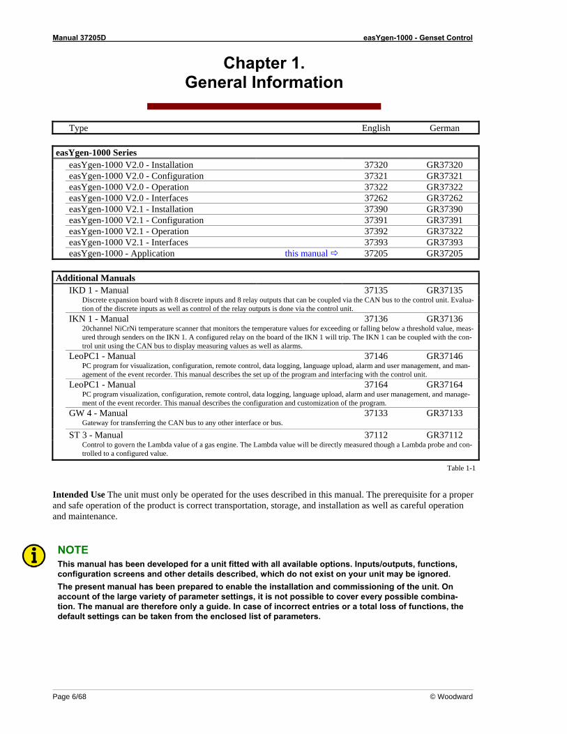
Type English German easYgen-1000 Series easYgen-1000 V2.0 - Installation 37320 GR37320 easYgen-1000 V2.0 - Configuration 37321 GR37321 easYgen-1000 V2.0 - Operation 37322 GR37322 easYgen-1000 V2.0 - Interfaces 37262 GR37262 easYgen-1000 V2.1 - Installation 37390 GR37390 easYgen-1000 V2.1 - Configuration 37391 GR37391 easYgen-1000 V2.1 - Operation 37392 GR37322 easYgen-1000 V2.1 - Interfaces 37393 GR37393 easYgen-1000 - Application this manual 37205 GR37205 Additional Manuals IKD 1 - Manual 37135 GR37135 Discrete expansion board with 8 discrete inputs and 8 relay outputs that can be coupled via the CAN bus to the control unit. Evalua-
tion of the discrete inputs as well as control of the relay outputs is done via the control unit. IKN 1 - Manual 37136 GR37136 20channel NiCrNi temperature scanner that monitors the temperature values for exceeding or falling below a threshold value, meas-
ured through senders on the IKN 1. A configured relay on the board of the IKN 1 will trip. The IKN 1 can be coupled with the con-trol unit using the CAN bus to display measuring values as well as alarms.
LeoPC1 - Manual 37146 GR37146 PC program for visualization, configuration, remote control, data logging, language upload, alarm and user management, and man-
agement of the event recorder. This manual describes the set up of the program and interfacing with the control unit. LeoPC1 - Manual 37164 GR37164 PC program visualization, configuration, remote control, data logging, language upload, alarm and user management, and manage-
ment of the event recorder. This manual describes the configuration and customization of the program. GW 4 - Manual 37133 GR37133 Gateway for transferring the CAN bus to any other interface or bus.
ST 3 - Manual 37112 GR37112 Control to govern the Lambda value of a gas engine. The Lambda value will be directly measured though a Lambda probe and con-
trolled to a configured value.
Table 1-1
Intended Use The unit must only be operated for the uses described in this manual. The prerequisite for a proper and safe operation of the product is correct transportation, storage, and installation as well as careful operation and maintenance.
NOTE This manual has been developed for a unit fitted with all available options. Inputs/outputs, functions, configuration screens and other details described, which do not exist on your unit may be ignored. The present manual has been prepared to enable the installation and commissioning of the unit. On account of the large variety of parameter settings, it is not possible to cover every possible combina-tion. The manual are therefore only a guide. In case of incorrect entries or a total loss of functions, the default settings can be taken from the enclosed list of parameters.
Manual 37205D easYgen-1000 - Genset Control
© Woodward Page 7/68
Chapter 2. Application Notes Starting Firmware V1.0016
Rated Voltage / Frequency Mains ≡≡≡≡≡≡≡≡≡≡≡≡≡≡≡≡≡≡≡≡≡≡≡≡≡
The proportional values for emergency mode relate to the generator nominal voltage. The mains has no own pa-rameters yet (implemented in V1.0017).
Rated Voltage Generator ≡≡≡≡≡≡≡≡≡≡≡≡≡≡≡≡≡≡≡≡≡≡≡≡≡
The generator rated voltage relates to the secondary values of the generator voltage transformer. Since V1.0017 it relates to the primary values!
Close GCB in MANUAL Mode ≡≡≡≡≡≡≡≡≡≡≡≡≡≡≡≡≡≡≡≡≡≡≡≡≡
The generator undervoltage monitoring level 1 and 2 must be enabled to close the GCB in MANUAL mode.
Emergency Mode ≡≡≡≡≡≡≡≡≡≡≡≡≡≡≡≡≡≡≡≡≡≡≡≡≡
When the mains return after a mains failure and the DI release MCB is disabled, the GCB will stay closed as long as the mains settling time is active. After that the GCB will open and the generator will shutdown. To prevent a dead busbar the unit needs a signal for "Start req. in AUTO", see also Test With Load on page 18.

Manual 37205D easYgen-1000 - Genset Control
Page 8/68 © Woodward
Chapter 3. Application Notes Starting Firmware V1.0017
Preheating of Coolant Water ≡≡≡≡≡≡≡≡≡≡≡≡≡≡≡≡≡≡≡≡≡≡≡≡≡
To set up a preheating of the coolant water the following is required: 1 temperature sensor, connected to T1 or T2, e.g. PT100 1 free limit of this analog input 1 free relay output for the heating (here relay2) The temperature sensor is connected to the analog input (AI), here T1 (terminal 13/12). The first monitoring limit of this AI is set to the selected temperature, e.g. 10°C with a delay time of 3s. The alarm class will be "control", the monitoring is set to "Underrun", and self acknowledge to "YES". The level 2 monitoring can be used for high temperature monitoring.
Example for all parameters in analog input 1 Parameter, German
Setting Parameter, English
Type Pt100 TypeAuswahl Hardware 0 to 500Ohm select hardwareBeschreibung (nur über LeoPC1) Kuehlwassertemp / cool.water temp name (only via LeoPC1)Hysterese 1 Hysteresis Überwachung Stufe 1 Ein / ON MonitoringLimit Stufe 1 10 Limit level 1Verzögerung Stufe 1 3.00 s Delay level 1Überwachung Stufe 1 auf Untersch. / Underrun Monitoring level 1 atAlarmklasse Stufe 1 Steuer / control Alarm class level 1Selbstquittierend Stufe 1 Ja / Yes Self acknowledgeVerzögert d.Motordr. Stufe 1 Nein / No Delayed by engine Überwachung Stufe 2 Ein / ON Monitoring level 2Limit Stufe 2 90 Limit level 2Verzögerung Stufe 2 1.00 s Delay level 2Überwachung Stufe 2 auf Überschr / Overrun Monitoring level 2Alarmklasse Stufe 2 Klasse C / Class C Alarm class level 2Selbstquittierend Stufe 2 Nein / No Self acknowledgeVerzögert d.Motordr. Stufe 2 Nein / No Delayed by engine Drahtbruchüberw. Oben Monit. wire breakDrahtbruch Alarm Klasse B / Class B Wire break alarm classDrahtbruch selbstquitt. Nein / No Self acknowledge wire breakFilter 3 Filter
Manual 37205D easYgen-1000 - Genset Control
© Woodward Page 9/68
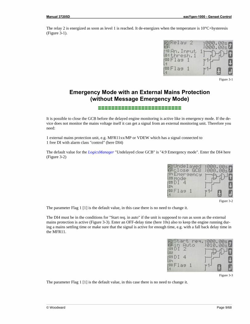
The relay 2 is energized as soon as level 1 is reached. It de-energizes when the temperature is 10°C+hysteresis (Figure 3-1).
Figure 3-1
Emergency Mode with an External Mains Protection (without Message Emergency Mode)
≡≡≡≡≡≡≡≡≡≡≡≡≡≡≡≡≡≡≡≡≡≡≡≡≡ It is possible to close the GCB before the delayed engine monitoring is active like in emergency mode. If the de-vice does not monitor the mains voltage itself it can get a signal from an external monitoring unit. Therefore you need: 1 external mains protection unit, e.g. MFR11xx/MP or VDEW which has a signal connected to 1 free DI with alarm class "control" (here DI4) The default value for the LogicsManager "Undelayed close GCB" is "4.9 Emergency mode". Enter the DI4 here (Figure 3-2)
Figure 3-2
The parameter Flag 1 [1] is the default value, in this case there is no need to change it. The DI4 must be in the conditions for "Start req. in auto" if the unit is supposed to run as soon as the external mains protection is active (Figure 3-3). Enter an OFF-delay time (here 10s) also to keep the engine running dur-ing a mains settling time or make sure that the signal is active for enough time, e.g. with a fall back delay time in the MFR11.
Figure 3-3
The parameter Flag 1 [1] is the default value, in this case there is no need to change it.
Manual 37205D easYgen-1000 - Genset Control
Page 10/68 © Woodward
Start in Auto Via Clock Daily/Weekly/Monthly ≡≡≡≡≡≡≡≡≡≡≡≡≡≡≡≡≡≡≡≡≡≡≡≡≡
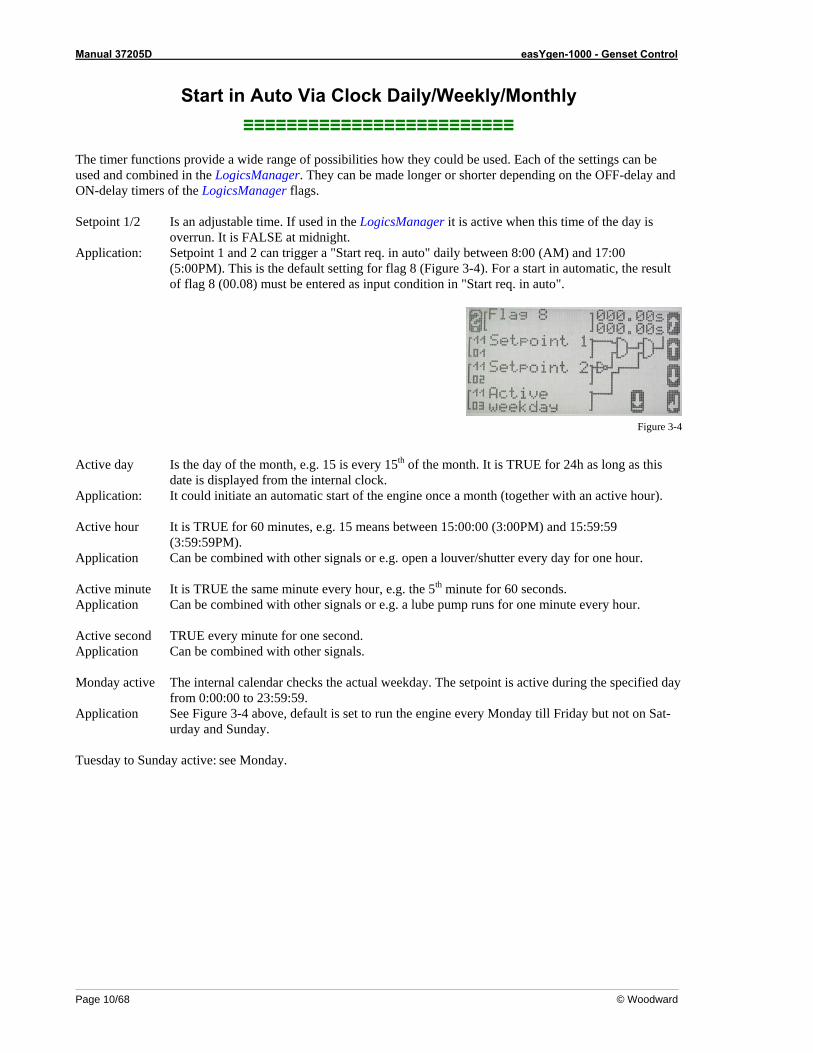
The timer functions provide a wide range of possibilities how they could be used. Each of the settings can be used and combined in the LogicsManager. They can be made longer or shorter depending on the OFF-delay and ON-delay timers of the LogicsManager flags. Setpoint 1/2 Is an adjustable time. If used in the LogicsManager it is active when this time of the day is
overrun. It is FALSE at midnight. Application: Setpoint 1 and 2 can trigger a "Start req. in auto" daily between 8:00 (AM) and 17:00
(5:00PM). This is the default setting for flag 8 (Figure 3-4). For a start in automatic, the result of flag 8 (00.08) must be entered as input condition in "Start req. in auto".
Figure 3-4
Active day Is the day of the month, e.g. 15 is every 15th of the month. It is TRUE for 24h as long as this
date is displayed from the internal clock. Application: It could initiate an automatic start of the engine once a month (together with an active hour). Active hour It is TRUE for 60 minutes, e.g. 15 means between 15:00:00 (3:00PM) and 15:59:59
(3:59:59PM). Application Can be combined with other signals or e.g. open a louver/shutter every day for one hour. Active minute It is TRUE the same minute every hour, e.g. the 5th minute for 60 seconds. Application Can be combined with other signals or e.g. a lube pump runs for one minute every hour. Active second TRUE every minute for one second. Application Can be combined with other signals. Monday active The internal calendar checks the actual weekday. The setpoint is active during the specified day
from 0:00:00 to 23:59:59. Application See Figure 3-4 above, default is set to run the engine every Monday till Friday but not on Sat-
urday and Sunday. Tuesday to Sunday active: see Monday.
Manual 37205D easYgen-1000 - Genset Control
© Woodward Page 11/68
Special Functions for Discrete Inputs, e.g. External Acknowledge and Firing Speed
≡≡≡≡≡≡≡≡≡≡≡≡≡≡≡≡≡≡≡≡≡≡≡≡≡
Firing Speed Reached (from V1.0100 with LogicsManager) A discrete input can be used as a signal that the firing speed is reached e.g. from an electrical generator. Firing speed reached means the starter is de-energized, the delayed engine monitoring timer starts and this DI will be monitored with the "Speed/frequency mismatch" monitoring. Example (high signal = firing speed reached), here for DI3: Configure engine DI for firing speed = 3 Configure digital inputs DI3 operation = N.O. DI3 delay = min 80ms, depending on application Alarm class = Control DI3 delayed by engine speed = No DI3 self acknowledge = No
External Acknowledgement (from V1.0100 with LogicsManager) This DI needs a high signal twice, the first to shut off the horn, the second to acknowledge all alarm messages. If a momentary-contact switch is used please make a label saying it has to be pushed twice. The duration of pushing depends on the setting of the DI delay time.
Examples of How To Define the Analog Input Tables ≡≡≡≡≡≡≡≡≡≡≡≡≡≡≡≡≡≡≡≡≡≡≡≡≡
If a sensor type is used that has no selectable characteristic, the table A and B can be used. It is possible to choose every point on the X-axis as well from the Y-axis. The X-axis offers values between 0 and 100%, this is the minimum and maximum of the configured hardware range. The device creates a straight line between the single points internally. It also creates a straight line be-tween 0% and the first entered value and between the last entered value and 100%. Here in this example: last entered value X=50% Y= -2000 The unit displays always the value –2000 between 250 and 500 Ohms
(or 10-20mA) The range for the Y-axis is –9999 to +9999. It has no dimension and no decimals. For values greater than –999 the parameter value format needs five zeros, the minus symbol needs one. For decimal values a decimal point is required in the parameter value format, e.g. 000.0°F, see also Display the Analog Input Value in °F and psi on page 19. value format = 00000 (only via LeoPC1) All zeros in this parameter will be overwritten with the actual meas-ured value 0%= 0Ohm and 100%= 500Ohm
Manual 37205D easYgen-1000 - Genset Control
Page 12/68 © Woodward
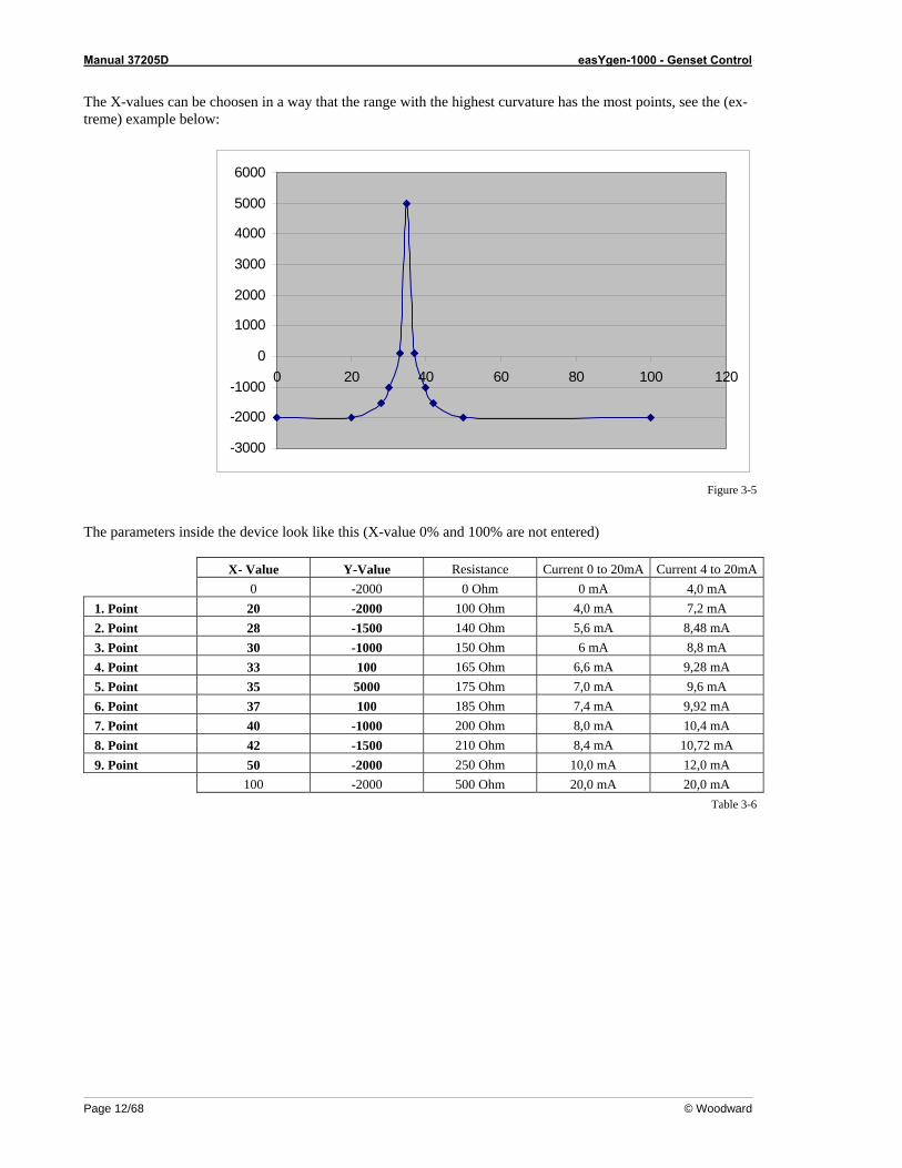
The X-values can be choosen in a way that the range with the highest curvature has the most points, see the (ex-treme) example below:
-3000
-2000
-1000
0
1000
2000
3000
4000
5000
6000
0 20 40 60 80 100 120
Figure 3-5
The parameters inside the device look like this (X-value 0% and 100% are not entered) X- Value Y-Value Resistance Current 0 to 20mA Current 4 to 20mA 0 -2000 0 Ohm 0 mA 4,0 mA
1. Point 20 -2000 100 Ohm 4,0 mA 7,2 mA 2. Point 28 -1500 140 Ohm 5,6 mA 8,48 mA 3. Point 30 -1000 150 Ohm 6 mA 8,8 mA 4. Point 33 100 165 Ohm 6,6 mA 9,28 mA 5. Point 35 5000 175 Ohm 7,0 mA 9,6 mA 6. Point 37 100 185 Ohm 7,4 mA 9,92 mA 7. Point 40 -1000 200 Ohm 8,0 mA 10,4 mA 8. Point 42 -1500 210 Ohm 8,4 mA 10,72 mA 9. Point 50 -2000 250 Ohm 10,0 mA 12,0 mA
100 -2000 500 Ohm 20,0 mA 20,0 mA Table 3-6
Manual 37205D easYgen-1000 - Genset Control
© Woodward Page 13/68
Using an Analog Input Instead of a Discrete Input ≡≡≡≡≡≡≡≡≡≡≡≡≡≡≡≡≡≡≡≡≡≡≡≡≡
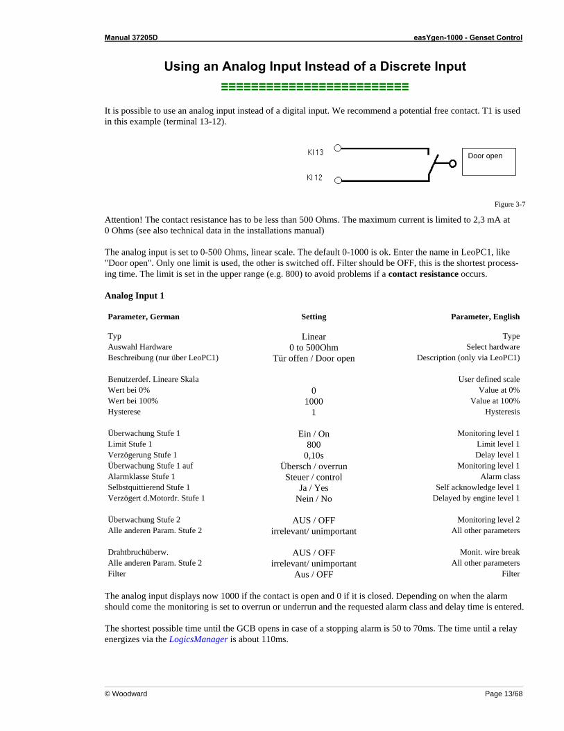
It is possible to use an analog input instead of a digital input. We recommend a potential free contact. T1 is used in this example (terminal 13-12).
Door open
Figure 3-7
Attention! The contact resistance has to be less than 500 Ohms. The maximum current is limited to 2,3 mA at 0 Ohms (see also technical data in the installations manual) The analog input is set to 0-500 Ohms, linear scale. The default 0-1000 is ok. Enter the name in LeoPC1, like "Door open". Only one limit is used, the other is switched off. Filter should be OFF, this is the shortest process-ing time. The limit is set in the upper range (e.g. 800) to avoid problems if a contact resistance occurs. Analog Input 1 Parameter, German
Setting Parameter, English
Typ Linear TypeAuswahl Hardware 0 to 500Ohm Select hardwareBeschreibung (nur über LeoPC1) Tür offen / Door open Description (only via LeoPC1) Benutzerdef. Lineare Skala User defined scaleWert bei 0% 0 Value at 0%Wert bei 100% 1000 Value at 100%Hysterese 1 Hysteresis Überwachung Stufe 1 Ein / On Monitoring level 1Limit Stufe 1 800 Limit level 1Verzögerung Stufe 1 0,10s Delay level 1Überwachung Stufe 1 auf Übersch / overrun Monitoring level 1Alarmklasse Stufe 1 Steuer / control Alarm classSelbstquittierend Stufe 1 Ja / Yes Self acknowledge level 1Verzögert d.Motordr. Stufe 1 Nein / No Delayed by engine level 1 Überwachung Stufe 2 AUS / OFF Monitoring level 2Alle anderen Param. Stufe 2 irrelevant/ unimportant All other parameters Drahtbruchüberw. AUS / OFF Monit. wire breakAlle anderen Param. Stufe 2 irrelevant/ unimportant All other parameters Filter Aus / OFF Filter
The analog input displays now 1000 if the contact is open and 0 if it is closed. Depending on when the alarm should come the monitoring is set to overrun or underrun and the requested alarm class and delay time is entered. The shortest possible time until the GCB opens in case of a stopping alarm is 50 to 70ms. The time until a relay energizes via the LogicsManager is about 110ms.
Manual 37205D easYgen-1000 - Genset Control
Page 14/68 © Woodward
Critical Mode (Sprinkler Operation) ≡≡≡≡≡≡≡≡≡≡≡≡≡≡≡≡≡≡≡≡≡≡≡≡≡
This LogicsManager flag is only active in automatic mode. There is no critical mode in manual mode, all alarms keep their alarm classes.
General All shutdown alarms become only warning alarms during critical mode. This mode is for a fire pump that is con-nected to the genset (before the GCB).
Alarm classes Class A remains A Class B remains B Class C becomes B Class D becomes B Class E becomes B Class F becomes B So a stop of the engine can only come from the settings in the LogicsManager, e.g. "Start fail" as a protection of the starter and DI1 emergency stop. These are default settings and can be changed if necessary. The number of start attempts is fixed to 10, in V1.0100 it is selectable The engine provides a normal cooldown phase if the LogicsManager flag "critical mode" becomes FALSE. All existing alarms get their original alarm classes and might stop the engine now!
Stop Engine During Critical Mode Manually Switch to MANUAL mode: Press the start/stop button. All alarms return to their original alarm classes. Switch to STOP mode: Press the STOP button once and the engine will stop with a cooldown. Press the STOP button twice and it will stop the engine immediately without a cooldown. All alarms return to their original alarm classes.
Critical Mode and Emergency Power Simultaneously {2oc} The emergency power operation has priority. If a mains failure occurs during critical mode, the generator will supply the busbar. Therefore the MCB will be opened and the GCB will be closed. A message "Emerg/Critical" or "Notstrom/Sprinkler" (German) is displayed. All shutdown alarms become warning alarms. Critical mode ends before mains recovery: The emergency power operation will be continued and all shutdown alarms will become active again. If the mains return, the unit transfers the load after the mains settling time from generator supply back to mains supply. Emergency power operation ends before the end of the critical mode: The critical mode is maintained and after the expiration of the mains settling time the load is transferred from generator supply to mains supply. The en-gine remains running until the conditions for the critical mode become FALSE.
Manual 37205D easYgen-1000 - Genset Control
© Woodward Page 15/68
Critical Mode and Start Request The critical mode operation has priority. If there is a critical mode request while the generator is running, the GCB will open (in application mode {2oc} the mains will take over the load). A message "Critical mode" or "Sprinklerbetrieb" (German) is displayed. All shutdown alarms become warning alarms. Critical mode ends before the start request: The engine keeps running, in {2oc} there will be a change from mains to generator supply. All shutdown alarms will become active again. After resetting the start request the GCB will open and the engine will shutdown after a cooldown. Start request is terminated before critical mode: The critical operation is continued. The engine keeps running un-til the conditions for critical mode are FALSE. The engine will shutdown after a cooldown.
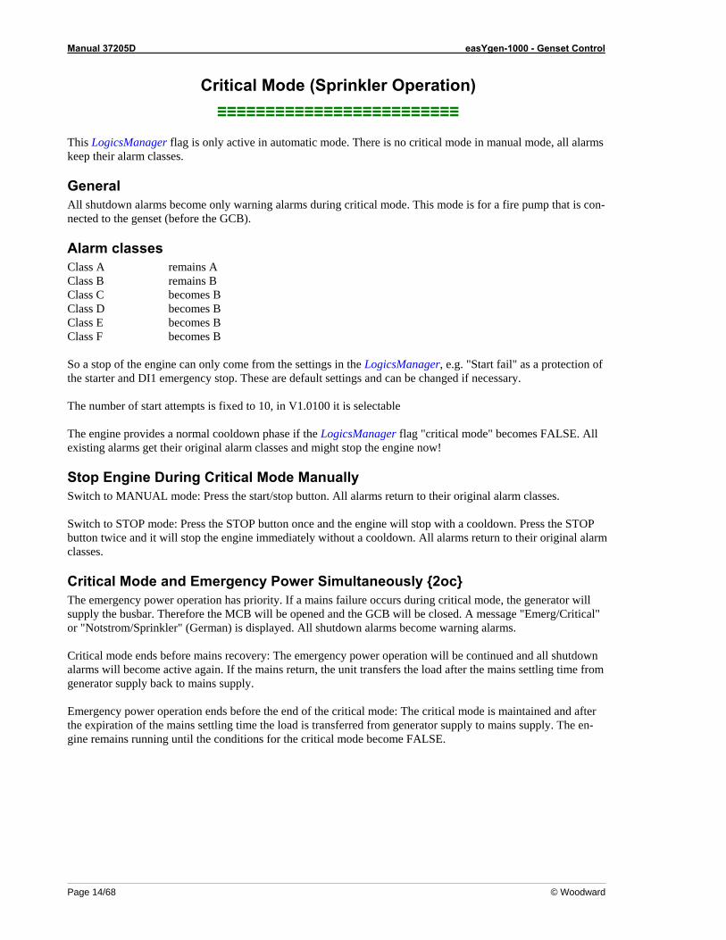
Configure Critical Mode All default settings are suggestions. They can be changed depending on the requirements. Two parameters have to be changed to activate a critical mode with the default settings: Remove the "0" for flag 3 in "critical mode" (configure engine->start/stop -> critical mode V1.0017, or in con-figure application->critical mode V1.0100). Then it should look like Figure 3-8.
Figure 3-8
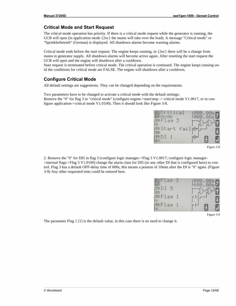
2. Remove the "0" for DI5 in flag 3 (configure logic manager->Flag 3 V1.0017; configure logic manager->internal flags->Flag 3 V1.0100) change the alarm class for DI5 (or any other DI that is configured here) to con-trol. Flag 3 has a default OFF-delay time of 600s, this means a postrun of 10min after the DI is "0" again. (Figure 3-9) Any other requested time could be entered here.
Figure 3-9
The parameter Flag 1 [1] is the default value, in this case there is no need to change it.
Manual 37205D easYgen-1000 - Genset Control
Page 16/68 © Woodward
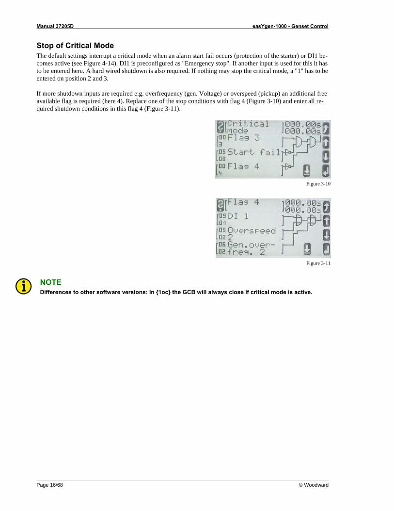
Stop of Critical Mode The default settings interrupt a critical mode when an alarm start fail occurs (protection of the starter) or DI1 be-comes active (see Figure 4-14). DI1 is preconfigured as "Emergency stop". If another input is used for this it has to be entered here. A hard wired shutdown is also required. If nothing may stop the critical mode, a "1" has to be entered on position 2 and 3. If more shutdown inputs are required e.g. overfrequency (gen. Voltage) or overspeed (pickup) an additional free available flag is required (here 4). Replace one of the stop conditions with flag 4 (Figure 3-10) and enter all re-quired shutdown conditions in this flag 4 (Figure 3-11).
Figure 3-10
Figure 3-11
NOTE Differences to other software versions: In {1oc} the GCB will always close if critical mode is active.
Manual 37205D easYgen-1000 - Genset Control
© Woodward Page 17/68
Load Shedding ≡≡≡≡≡≡≡≡≡≡≡≡≡≡≡≡≡≡≡≡≡≡≡≡≡
The device has internal load limits for the generator and the mains. A load shed via the generator power is set like below: Configure LogicsManager Gen. load limit 1 or 2 = enter requested load limit, the value relates to the generator rated active
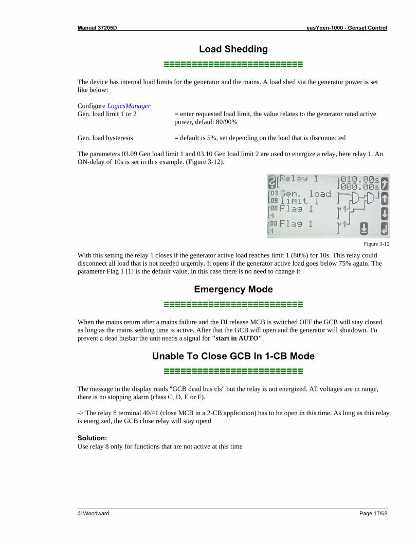
power, default 80/90% Gen. load hysteresis = default is 5%, set depending on the load that is disconnected The parameters 03.09 Gen load limit 1 and 03.10 Gen load limit 2 are used to energize a relay, here relay 1. An ON-delay of 10s is set in this example. (Figure 3-12).
Figure 3-12
With this setting the relay 1 closes if the generator active load reaches limit 1 (80%) for 10s. This relay could disconnect all load that is not needed urgently. It opens if the generator active load goes below 75% again. The parameter Flag 1 [1] is the default value, in this case there is no need to change it.
Emergency Mode ≡≡≡≡≡≡≡≡≡≡≡≡≡≡≡≡≡≡≡≡≡≡≡≡≡
When the mains return after a mains failure and the DI release MCB is switched OFF the GCB will stay closed as long as the mains settling time is active. After that the GCB will open and the generator will shutdown. To prevent a dead busbar the unit needs a signal for "start in AUTO".
Unable To Close GCB In 1-CB Mode ≡≡≡≡≡≡≡≡≡≡≡≡≡≡≡≡≡≡≡≡≡≡≡≡≡
The message in the display reads "GCB dead bus cls" but the relay is not energized. All voltages are in range, there is no stopping alarm (class C, D, E or F). -> The relay 8 terminal 40/41 (close MCB in a 2-CB application) has to be open in this time. As long as this relay is energized, the GCB close relay will stay open! Solution: Use relay 8 only for functions that are not active at this time
Manual 37205D easYgen-1000 - Genset Control
Page 18/68 © Woodward
Chapter 4. Application Notes Starting Firmware V1.0100
NOTE This version requires LeoPC1 V 3.1.000 or higher! Older versions don't display the LogicsManager cor-rectly.
Test Mode: How To Set Up a Test with or without Load ≡≡≡≡≡≡≡≡≡≡≡≡≡≡≡≡≡≡≡≡≡≡≡≡≡
There are a lot of different opinions of the behavior of a proper test mode. The easYgen-1500 can support the following two modes: Test with load and test without load. Both modes work only in automatic mode. The cor-rect test mode depends on your local specifications.
Test With Load This is the start in automatic mode in the block "Configure application". No special message appears on the dis-play. If the mains fail during start in auto the unit keeps running until the mains return and the mains settling time is expired or the conditions for "Start in auto" are FALSE again. It depends on which is longer active.
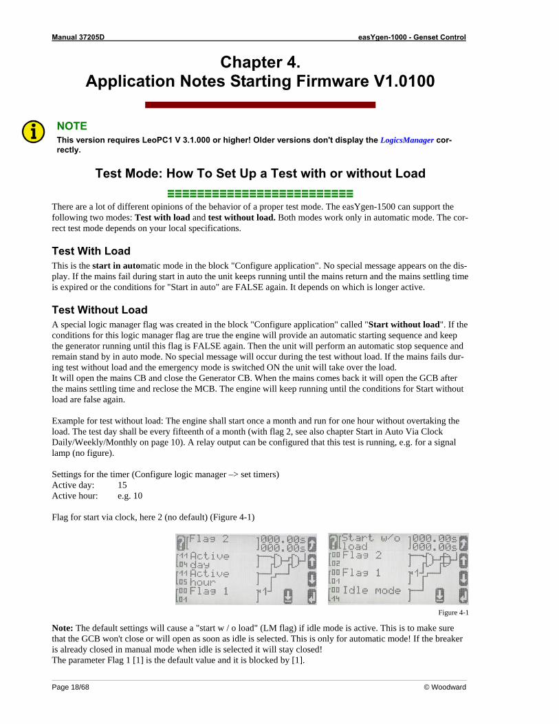
Test Without Load A special logic manager flag was created in the block "Configure application" called "Start without load". If the conditions for this logic manager flag are true the engine will provide an automatic starting sequence and keep the generator running until this flag is FALSE again. Then the unit will perform an automatic stop sequence and remain stand by in auto mode. No special message will occur during the test without load. If the mains fails dur-ing test without load and the emergency mode is switched ON the unit will take over the load. It will open the mains CB and close the Generator CB. When the mains comes back it will open the GCB after the mains settling time and reclose the MCB. The engine will keep running until the conditions for Start without load are false again. Example for test without load: The engine shall start once a month and run for one hour without overtaking the load. The test day shall be every fifteenth of a month (with flag 2, see also chapter Start in Auto Via Clock Daily/Weekly/Monthly on page 10). A relay output can be configured that this test is running, e.g. for a signal lamp (no figure). Settings for the timer (Configure logic manager –> set timers) Active day: 15 Active hour: e.g. 10 Flag for start via clock, here 2 (no default) (Figure 4-1)
Figure 4-1
Note: The default settings will cause a "start w / o load" (LM flag) if idle mode is active. This is to make sure that the GCB won't close or will open as soon as idle is selected. This is only for automatic mode! If the breaker is already closed in manual mode when idle is selected it will stay closed! The parameter Flag 1 [1] is the default value and it is blocked by [1].
Manual 37205D easYgen-1000 - Genset Control
© Woodward Page 19/68
Display the Analog Input Value in °F and psi ≡≡≡≡≡≡≡≡≡≡≡≡≡≡≡≡≡≡≡≡≡≡≡≡≡≡≡≡≡≡≡≡≡≡≡≡
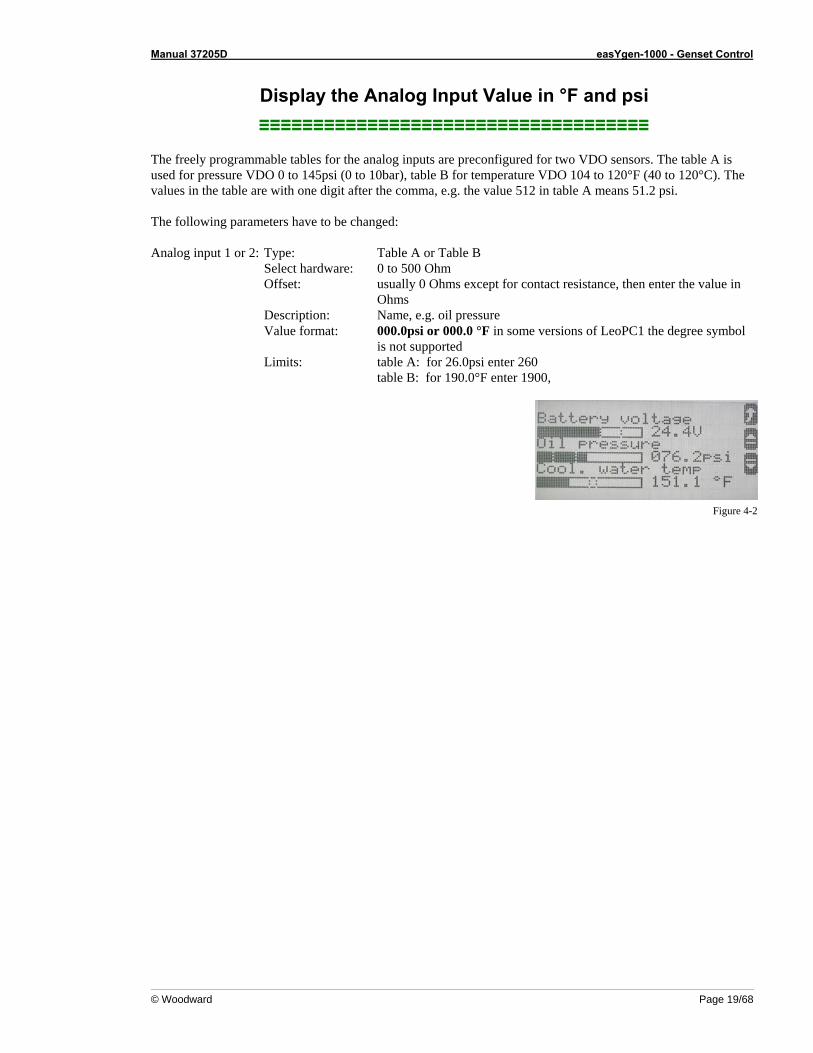
The freely programmable tables for the analog inputs are preconfigured for two VDO sensors. The table A is used for pressure VDO 0 to 145psi (0 to 10bar), table B for temperature VDO 104 to 120°F (40 to 120°C). The values in the table are with one digit after the comma, e.g. the value 512 in table A means 51.2 psi. The following parameters have to be changed: Analog input 1 or 2: Type: Table A or Table B Select hardware: 0 to 500 Ohm Offset: usually 0 Ohms except for contact resistance, then enter the value in
Ohms Description: Name, e.g. oil pressure Value format: 000.0psi or 000.0 °F in some versions of LeoPC1 the degree symbol
is not supported Limits: table A: for 26.0psi enter 260 table B: for 190.0°F enter 1900,
Figure 4-2
Manual 37205D easYgen-1000 - Genset Control
Page 20/68 © Woodward
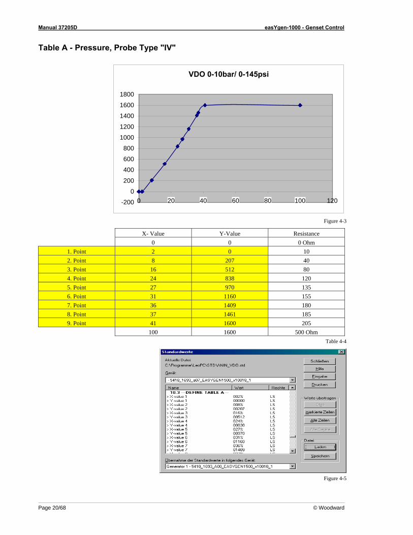
Table A - Pressure, Probe Type "IV"
VDO 0-10bar/ 0-145psi
-200
0
200
400
600
800
1000
1200
1400
1600
1800
0 20 40 60 80 100 120
Figure 4-3
X- Value Y-Value Resistance 0 0 0 Ohm
1. Point 2 0 10 2. Point 8 207 40 3. Point 16 512 80 4. Point 24 838 120 5. Point 27 970 135 6. Point 31 1160 155 7. Point 36 1409 180 8. Point 37 1461 185 9. Point 41 1600 205
100 1600 500 Ohm Table 4-4
Figure 4-5
Manual 37205D easYgen-1000 - Genset Control
© Woodward Page 21/68
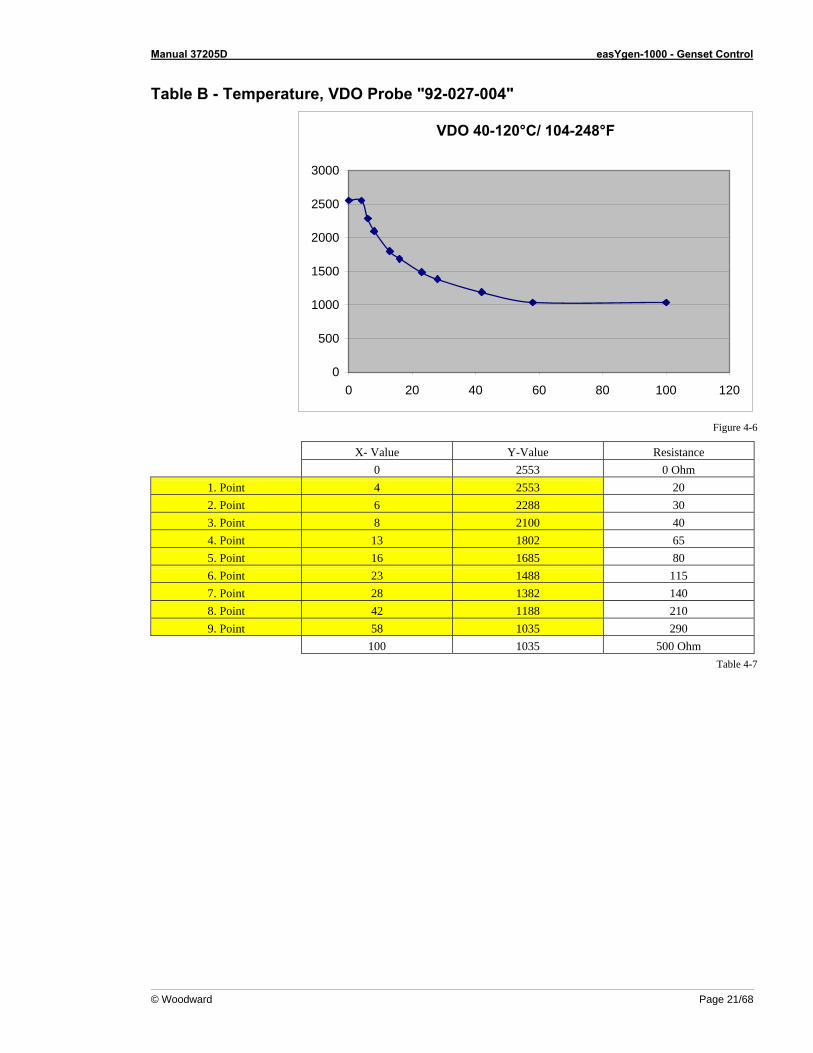
Table B - Temperature, VDO Probe "92-027-004"
VDO 40-120°C/ 104-248°F
0
500
1000
1500
2000
2500
3000
0 20 40 60 80 100 120
Figure 4-6
X- Value Y-Value Resistance 0 2553 0 Ohm
1. Point 4 2553 20 2. Point 6 2288 30 3. Point 8 2100 40 4. Point 13 1802 65 5. Point 16 1685 80 6. Point 23 1488 115 7. Point 28 1382 140 8. Point 42 1188 210 9. Point 58 1035 290
100 1035 500 Ohm Table 4-7

Manual 37205D easYgen-1000 - Genset Control
Page 22/68 © Woodward
Emergency Mode Ends and the Release of the MCB Is Switched OFF (Meet NFPA) ≡≡≡≡≡≡≡≡≡≡≡≡≡≡≡≡≡≡≡≡≡≡≡≡≡
When the emergency mode ends and the MCB release (terminal 6) is switched OFF the GCB will open (after mains settling time) and cooldown. To prevent a black busbar in this case and to meet the NFPA requirements the default settings for "start in auto" are set like below (Figure 4-8). Make sure that flag 7 looks like the default setting in Figure 4-9 below.
Figure 4-8
Figure 4-9
Now the flag "Start in auto" will come TRUE when the mains release is "0" (parameter 9.06) and the reply for the MCB is open (9.7) and the mains voltage and frequency is in range (2.11). The generator will keep running until the release for the MCB is "1" again. An OFF delay time longer than the "mains fail delay time" might help in case the mains fails in this condition again.
Manual 37205D easYgen-1000 - Genset Control
© Woodward Page 23/68
Using a Key Switch to Change Between Local and External Control: New LogicsManager (LM) Flags for
Operation Mode AUTO, MAN, STOP ≡≡≡≡≡≡≡≡≡≡≡≡≡≡≡≡≡≡≡≡≡≡≡≡≡
The following parameters are required if a key switch shall change between external and local control. Local control: the operation modes can be selected via the push buttons on the front. This is the normal
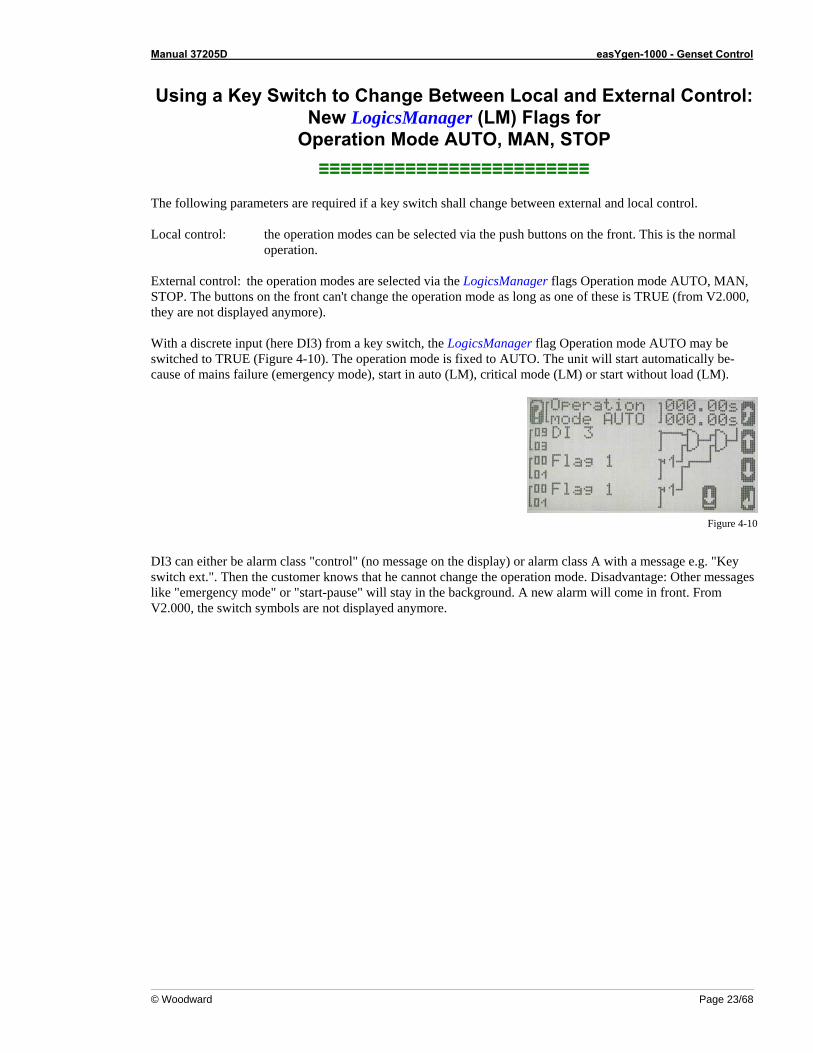
operation. External control: the operation modes are selected via the LogicsManager flags Operation mode AUTO, MAN, STOP. The buttons on the front can't change the operation mode as long as one of these is TRUE (from V2.000, they are not displayed anymore). With a discrete input (here DI3) from a key switch, the LogicsManager flag Operation mode AUTO may be switched to TRUE (Figure 4-10). The operation mode is fixed to AUTO. The unit will start automatically be-cause of mains failure (emergency mode), start in auto (LM), critical mode (LM) or start without load (LM).
Figure 4-10
DI3 can either be alarm class "control" (no message on the display) or alarm class A with a message e.g. "Key switch ext.". Then the customer knows that he cannot change the operation mode. Disadvantage: Other messages like "emergency mode" or "start-pause" will stay in the background. A new alarm will come in front. From V2.000, the switch symbols are not displayed anymore.
Manual 37205D easYgen-1000 - Genset Control
Page 24/68 © Woodward
New LogicsManager (LM) Flags: External Acknowledge and Firing Speed
≡≡≡≡≡≡≡≡≡≡≡≡≡≡≡≡≡≡≡≡≡≡≡≡≡
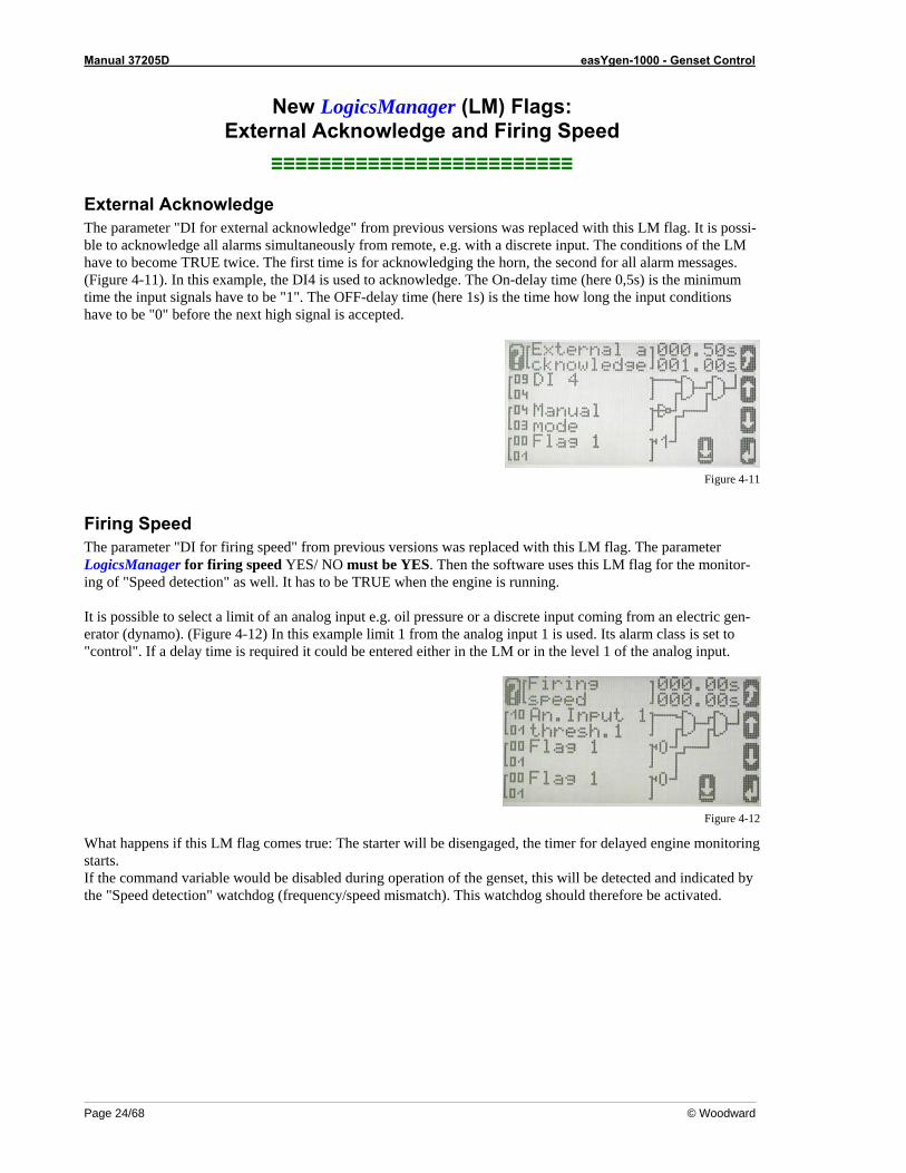
External Acknowledge The parameter "DI for external acknowledge" from previous versions was replaced with this LM flag. It is possi-ble to acknowledge all alarms simultaneously from remote, e.g. with a discrete input. The conditions of the LM have to become TRUE twice. The first time is for acknowledging the horn, the second for all alarm messages. (Figure 4-11). In this example, the DI4 is used to acknowledge. The On-delay time (here 0,5s) is the minimum time the input signals have to be "1". The OFF-delay time (here 1s) is the time how long the input conditions have to be "0" before the next high signal is accepted.
Figure 4-11
Firing Speed The parameter "DI for firing speed" from previous versions was replaced with this LM flag. The parameter LogicsManager for firing speed YES/ NO must be YES. Then the software uses this LM flag for the monitor-ing of "Speed detection" as well. It has to be TRUE when the engine is running. It is possible to select a limit of an analog input e.g. oil pressure or a discrete input coming from an electric gen-erator (dynamo). (Figure 4-12) In this example limit 1 from the analog input 1 is used. Its alarm class is set to "control". If a delay time is required it could be entered either in the LM or in the level 1 of the analog input.
Figure 4-12
What happens if this LM flag comes true: The starter will be disengaged, the timer for delayed engine monitoring starts. If the command variable would be disabled during operation of the genset, this will be detected and indicated by the "Speed detection" watchdog (frequency/speed mismatch). This watchdog should therefore be activated.
Manual 37205D easYgen-1000 - Genset Control
© Woodward Page 25/68
Duplicate Circuit Breaker Close Command for Special Applications/Circuit Breakers (e.g. ABB)
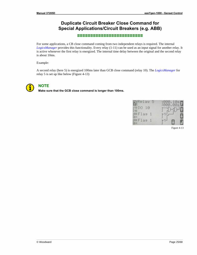
≡≡≡≡≡≡≡≡≡≡≡≡≡≡≡≡≡≡≡≡≡≡≡≡≡ For some applications, a CB close command coming from two independent relays is required. The internal LogicsManager provides this functionality. Every relay (1-11) can be used as an input signal for another relay. It is active whenever the first relay is energized. The internal time delay between the original and the second relay is about 10ms. Example: A second relay (here 5) is energized 100ms later than GCB close command (relay 10). The LogicsManager for relay 5 is set up like below (Figure 4-13)
NOTE Make sure that the GCB close command is longer than 100ms.
Figure 4-13
Manual 37205D easYgen-1000 - Genset Control
Page 26/68 © Woodward
Idle/Rated Speed ≡≡≡≡≡≡≡≡≡≡≡≡≡≡≡≡≡≡≡≡≡≡≡≡≡
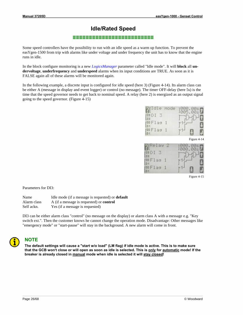
Some speed controllers have the possibility to run with an idle speed as a warm up function. To prevent the easYgen-1500 from trip with alarms like under voltage and under frequency the unit has to know that the engine runs in idle. In the block configure monitoring is a new LogicsManager parameter called "Idle mode". It will block all un-dervoltage, underfrequency and underspeed alarms when its input conditions are TRUE. As soon as it is FALSE again all of these alarms will be monitored again. In the following example, a discrete input is configured for idle speed (here 3) (Figure 4-14). Its alarm class can be either A (message in display and event logger) or control (no message). The timer OFF-delay (here 5s) is the time that the speed governor needs to get back to nominal speed. A relay (here 2) is energized as an output signal going to the speed governor. (Figure 4-15)
Figure 4-14
Figure 4-15
Parameters for DI3: Name Idle mode (if a message is requested) or default Alarm class A (if a message is requested) or control Self ackn. Yes (if a message is requested) DI3 can be either alarm class "control" (no message on the display) or alarm class A with a message e.g. "Key switch ext.". Then the customer knows he cannot change the operation mode. Disadvantage: Other messages like "emergency mode" or "start-pause" will stay in the background. A new alarm will come in front.
NOTE The default settings will cause a "start w/o load" (LM flag) if idle mode is active. This is to make sure that the GCB won't close or will open as soon as idle is selected. This is only for automatic mode! If the breaker is already closed in manual mode when idle is selected it will stay closed!
Manual 37205D easYgen-1000 - Genset Control
© Woodward Page 27/68
New Parameters for the Critical Mode ≡≡≡≡≡≡≡≡≡≡≡≡≡≡≡≡≡≡≡≡≡≡≡≡≡
The parameters have a new order in the easYgen: (Configure application->Critical mode)
Close GCB in Override The water pump is connected to the busbar, the GCB will close during critical mode is active.
NOTE If the LM "start w/o load" is active at the same time, the GCB will stay open. Please make sure that this cannot happen.
Override alarmcl. also in MAN Enter YES if it is requested to have no shutdown alarms in manual mode also.
Break Emergency in Override 0 = no break xxx seconds = this is the time how long the unit opens the GCB if emergency is active when critical
mode becomes active. In this case the complete power of the genset is available for the startup of the water pump (pump is connected before the GCB).
Start Attempts in Override The number of start attempts in the critical mode is selectable between 1 and 20. Regard the starter specifica-tions.
Manual 37205D easYgen-1000 - Genset Control
Page 28/68 © Woodward
Receive Data from the easYgen-1000 Via a GW4 Gateway ≡≡≡≡≡≡≡≡≡≡≡≡≡≡≡≡≡≡≡≡≡≡≡≡≡
It is possible to have up to 4 easYgens together with one GW4 connected to the CAN bus with different CAN device numbers and protocol type LeoPC1. Each of the easYgens needs an expanded block from the transmitting capability of the GW4.
For the Use of a GW4 with SW Version 2.0018 and Higher Configuration and visualization: In the GW4: Use the Protocol Type 3 and set "Expand block 1" = YES In LeoPC1: Devices->Settings->Service configuration->ID for the first setting for remote monitoring set to 50000
For the Use of a GW4 with SW Version Below 2.0018 Configuration: In the GW4: Use the Protocol Type 2 and say "Expand block 1" = YES In LeoPC1: Devices->Settings->Service Configuration->ID for the first setting for remote monitoring set to 50000 You'll find a detailed example about this under Connecting a GW 4 (GW 4 starting V2.0018) on page 46. Visualization: In the GW4: Use the Protocol type 2 and say "Expand block 1" = YES In LeoPC1: Devices->Settings->Service configuration->ID for the first setting for remote monitoring set to "0"
NOTE Not all J1939 visualization data is transmitted by the GW4. Further information about this can be found in manual 37133.
Manual 37205D easYgen-1000 - Genset Control
© Woodward Page 29/68
Problems with LeoPC1 During Read and Write of the Parameters ≡≡≡≡≡≡≡≡≡≡≡≡≡≡≡≡≡≡≡≡≡≡≡≡≡
NOTE LeoPC1 V3.1.xxx or higher must be installed to read and write the parameters for the LogicsManager correctly.
With some computers a crash may occur during reading/writing of parameters with LeoPC1. If this happens change the following settings: In LeoPC1 (English): Devices-> Settings-> (Data communication) Settings-> Options -> Timeout after writing a command, change to 100, this could also be another value (except 0), depending on the computer´s capacity LeoPC1 (Deutsch): Geräte-> Einstellungen-> (Datenkommunikation) Einstellungen-> Optionen-> Timeout nach dem Schreiben eines Befehls auf 100 setzen. Der Wert kann je nach PC-Leistung auch geringer oder höher eingestellt werden.
Connect 120V or 480V ≡≡≡≡≡≡≡≡≡≡≡≡≡≡≡≡≡≡≡≡≡≡≡≡≡
Depending on the parameter voltage transformer secondary the corresponding terminals have to be connected like this (each for generator and mains): From 50 to 120V: use 120V inputs From 121 to 480V: use 480V inputs Otherwise the reading of the voltage is incorrect. For PTs with 120V: If your voltage transformers are not very accurate and you like to adjust the PT ratio to cor-rect the displayed value change only the primary voltage.
Using the EG1500 Only for Start/Stop (No Voltage Connected) ≡≡≡≡≡≡≡≡≡≡≡≡≡≡≡≡≡≡≡≡≡≡≡≡≡≡≡≡≡≡≡≡≡≡≡≡≡≡≡≡≡≡≡≡≡≡≡≡≡≡≡
It is possible to use only the start/stop sequence of this unit e.g. for a single motor. The engines' voltage and cur-rent will not be connected to the easYgen. In this case the unit will monitor the speed via pickup and engine sig-nals like discrete and analog inputs. It can not operate a circuit breaker. It will still display the screens for the generator voltage and current but the ones for the mains can be switched off. The turning arrow in the generator symbol in the base screen displays a running engine. It is also possible to display the ECU data via CAN bus if connected. As there is no "GCB open" signal it might be necessary to configure a relay which energizes when a stopping alarm (parameter 1.09) occurs to open a breaker. In this application you will only use the monitoring of start/stop, pickup, 2 analog inputs and 8 discrete inputs.
Manual 37205D easYgen-1000 - Genset Control
Page 30/68 © Woodward
Configure application: The number is the same like in the LeoPC1 software. 2. Application mode: None (no circuit breaker available) 2. Show mains data : No (mains measuring screen will disappear) Switch OFF the following monitoring: The number is the same like in the LeoPC1 software.
6.1.3 Generator under frequency level 1 = OFF 6.1.4 Generator under frequency level 2 = OFF 6.1.7 Generator under voltage level 1 = OFF 6.1.8 Generator under voltage level 2 = OFF 6.4.5 Engine speed detection (f/n mismatch) = OFF
Stop cranking and start the timer for the delayed engine monitoring: The easYgen will stop cranking during startup when the pickup speed is over the firing speed limit. The level of an analog input (oil pressure) or a discrete input (oil pressure switch, signal from electrical generator - dynamo) can also stop cranking. In this case the LogicsManager flag "Firing speed" is used. The alarm class of this input is configured to "control". If a delay time is required it could be entered either in the LM or in the settings of this signal. The parameter LogicsManager for firing speed YES/ NO must be YES. Then the software uses this LM flag to stop cranking and the timer for the delayed engine monitoring starts.
CAUTION There is no monitoring if the input condition of the LogicsManager fails while the engine is running! Usually there is the engine speed detection (f/n mismatch) which takes care of this problem but this is not possible in this special application. If you want to use the LogicsManager you have to configure an extra monitoring limit for this "firing speed reached" signal.
Solution: A discrete input must be bridged to a second discrete input. An analog input needs the second level for the monitoring. Configure the second input and the second level to "delayed by engine speed" =YES. Verify that the monitoring is for the right state (NO/NC or over-/underrun) and configure the respective alarm class.
Manual 37205D easYgen-1000 - Genset Control
© Woodward Page 31/68
LogicsManager: Create self-toggling (pulsing) relays ≡≡≡≡≡≡≡≡≡≡≡≡≡≡≡≡≡≡≡≡≡≡≡≡≡≡≡≡≡≡≡≡≡≡≡≡≡≡≡≡≡≡≡≡
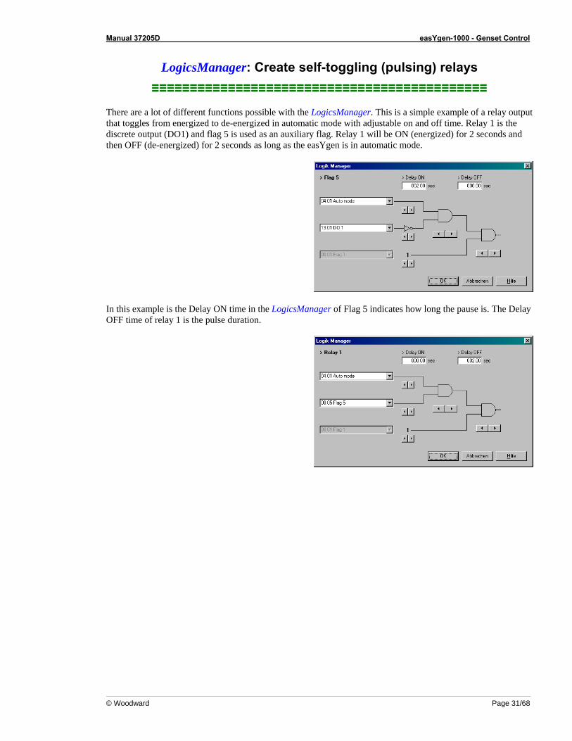
There are a lot of different functions possible with the LogicsManager. This is a simple example of a relay output that toggles from energized to de-energized in automatic mode with adjustable on and off time. Relay 1 is the discrete output (DO1) and flag 5 is used as an auxiliary flag. Relay 1 will be ON (energized) for 2 seconds and then OFF (de-energized) for 2 seconds as long as the easYgen is in automatic mode.
In this example is the Delay ON time in the LogicsManager of Flag 5 indicates how long the pause is. The Delay OFF time of relay 1 is the pulse duration.
Manual 37205D easYgen-1000 - Genset Control
Page 32/68 © Woodward
Chapter 5. Application Notes Starting Firmware V1.0200
Connecting an ECU with J1939 Protocol ≡≡≡≡≡≡≡≡≡≡≡≡≡≡≡≡≡≡≡≡≡≡≡≡≡≡≡≡≡≡≡≡≡
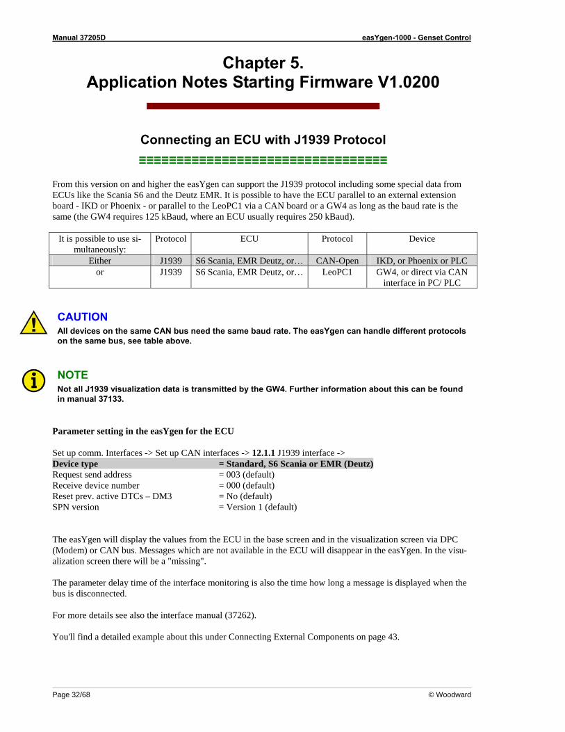
From this version on and higher the easYgen can support the J1939 protocol including some special data from ECUs like the Scania S6 and the Deutz EMR. It is possible to have the ECU parallel to an external extension board - IKD or Phoenix - or parallel to the LeoPC1 via a CAN board or a GW4 as long as the baud rate is the same (the GW4 requires 125 kBaud, where an ECU usually requires 250 kBaud).
It is possible to use si-multaneously:
Protocol ECU Protocol Device
Either J1939 S6 Scania, EMR Deutz, or… CAN-Open IKD, or Phoenix or PLC or J1939 S6 Scania, EMR Deutz, or… LeoPC1 GW4, or direct via CAN
interface in PC/ PLC
CAUTION All devices on the same CAN bus need the same baud rate. The easYgen can handle different protocols on the same bus, see table above.
NOTE Not all J1939 visualization data is transmitted by the GW4. Further information about this can be found in manual 37133.
Parameter setting in the easYgen for the ECU Set up comm. Interfaces -> Set up CAN interfaces -> 12.1.1 J1939 interface -> Device type = Standard, S6 Scania or EMR (Deutz) Request send address = 003 (default) Receive device number = 000 (default) Reset prev. active DTCs – DM3 = No (default) SPN version = Version 1 (default) The easYgen will display the values from the ECU in the base screen and in the visualization screen via DPC (Modem) or CAN bus. Messages which are not available in the ECU will disappear in the easYgen. In the visu-alization screen there will be a "missing". The parameter delay time of the interface monitoring is also the time how long a message is displayed when the bus is disconnected. For more details see also the interface manual (37262). You'll find a detailed example about this under Connecting External Components on page 43.
Manual 37205D easYgen-1000 - Genset Control
© Woodward Page 33/68
Connecting a Charging Alternator (D+) ≡≡≡≡≡≡≡≡≡≡≡≡≡≡≡≡≡≡≡≡≡≡≡≡≡≡≡≡≡≡≡≡
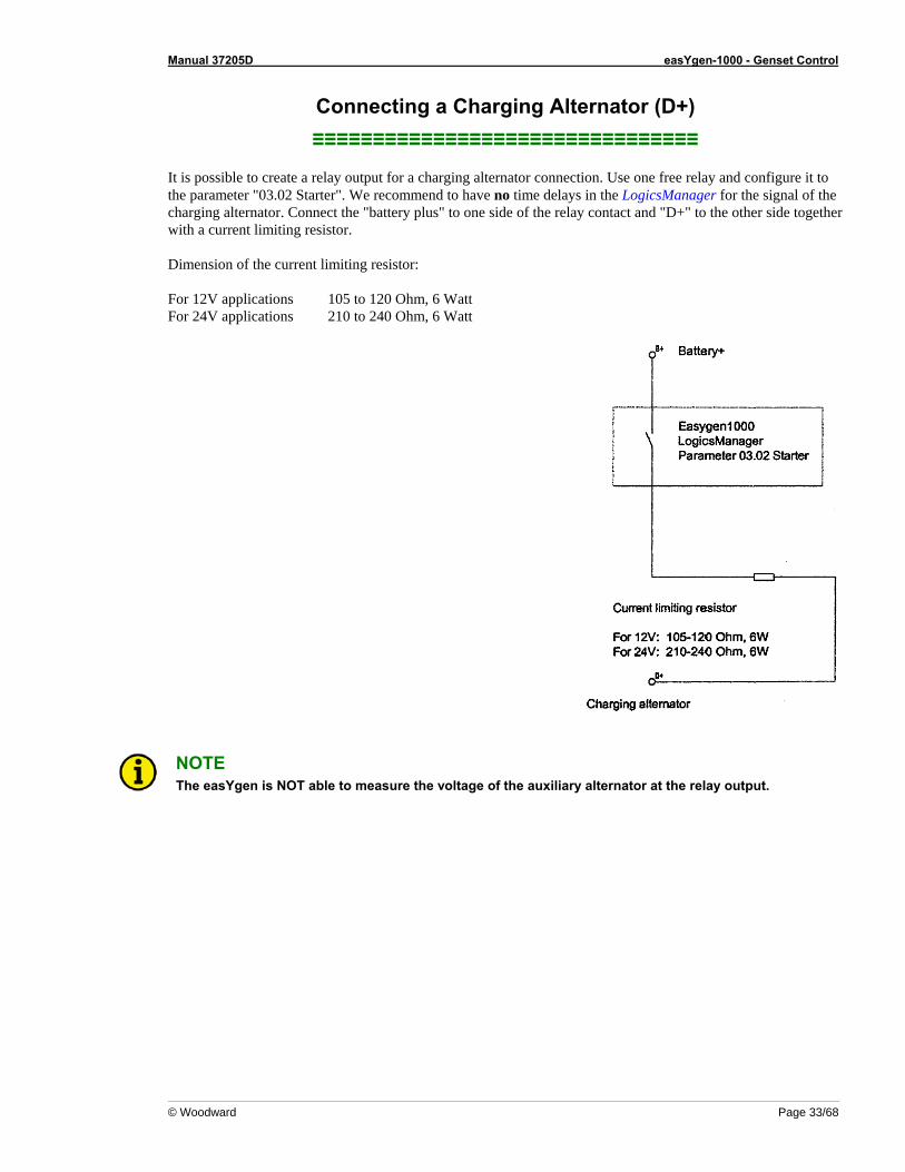
It is possible to create a relay output for a charging alternator connection. Use one free relay and configure it to the parameter "03.02 Starter". We recommend to have no time delays in the LogicsManager for the signal of the charging alternator. Connect the "battery plus" to one side of the relay contact and "D+" to the other side together with a current limiting resistor. Dimension of the current limiting resistor: For 12V applications 105 to 120 Ohm, 6 Watt For 24V applications 210 to 240 Ohm, 6 Watt
NOTE The easYgen is NOT able to measure the voltage of the auxiliary alternator at the relay output.
Manual 37205D easYgen-1000 - Genset Control
Page 34/68 © Woodward
Connecting a GSM Modem ≡≡≡≡≡≡≡≡≡≡≡≡≡≡≡≡≡≡≡≡≡≡≡≡≡≡≡≡≡≡≡≡≡
Laptop with modemLaptop with modemwith Windows operation systemwith Windows operation system
9x, NT, ME, 2000, XP9x, NT, ME, 2000, XPLeoPC LeoPC
configurationconfiguration and visualizationand visualization
e.g.e.g. INSYS INSYS GSM ModemGSM Modem
easYgen easYgen 15001500RJ45 socket edgewiseRJ45 socket edgewise
RS232RS232 RS232RS232
GalvanicGalvanicisolatedisolated
Configuration wireConfiguration wirewith galvanic isolation with galvanic isolation
(black box)(black box)DPCDPC--1 P/N 54171 P/N 5417--557557
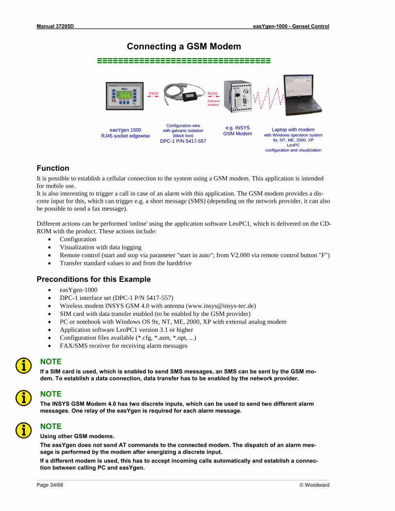
Function It is possible to establish a cellular connection to the system using a GSM modem. This application is intended for mobile use. It is also interesting to trigger a call in case of an alarm with this application. The GSM modem provides a dis-crete input for this, which can trigger e.g. a short message (SMS) (depending on the network provider, it can also be possible to send a fax message). Different actions can be performed 'online' using the application software LeoPC1, which is delivered on the CD-ROM with the product. These actions include:
• Configuration • Visualization with data logging • Remote control (start and stop via parameter "start in auto"; from V2.000 via remote control button "F") • Transfer standard values to and from the harddrive
Preconditions for this Example • easYgen-1000 • DPC-1 interface set (DPC-1 P/N 5417-557) • Wireless modem INSYS GSM 4.0 with antenna ([email protected]) • SIM card with data transfer enabled (to be enabled by the GSM provider) • PC or notebook with Windows OS 9x, NT, ME, 2000, XP with external analog modem • Application software LeoPC1 version 3.1 or higher • Configuration files available (*.cfg, *.asm, *.opt, ...) • FAX/SMS receiver for receiving alarm messages
NOTE If a SIM card is used, which is enabled to send SMS messages, an SMS can be sent by the GSM mo-dem. To establish a data connection, data transfer has to be enabled by the network provider.
NOTE The INSYS GSM Modem 4.0 has two discrete inputs, which can be used to send two different alarm messages. One relay of the easYgen is required for each alarm message.
NOTE Using other GSM modems. The easYgen does not send AT commands to the connected modem. The dispatch of an alarm mes-sage is performed by the modem after energizing a discrete input. If a different modem is used, this has to accept incoming calls automatically and establish a connec-tion between calling PC and easYgen.
Manual 37205D easYgen-1000 - Genset Control
© Woodward Page 35/68
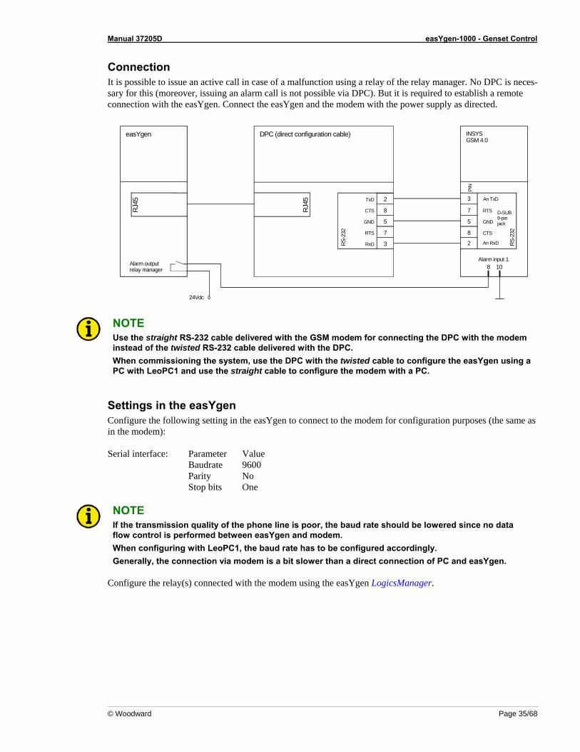
Connection It is possible to issue an active call in case of a malfunction using a relay of the relay manager. No DPC is neces-sary for this (moreover, issuing an alarm call is not possible via DPC). But it is required to establish a remote connection with the easYgen. Connect the easYgen and the modem with the power supply as directed.
RJ45
easYgen
RTS
GND
An RxD2
7
5
PIN
An TxD
CTS
RS-2
32
D-SUB9-pinjack
8
3
INSYSGSM 4.0
DPC (direct configuration cable)
CTS
GND
RxD
RTS
RS-2
32
5
7
3
TxD 2
8
Alarm outputrelay manager 8 10
Alarm input 1
RJ45
24Vdc
NOTE Use the straight RS-232 cable delivered with the GSM modem for connecting the DPC with the modem instead of the twisted RS-232 cable delivered with the DPC. When commissioning the system, use the DPC with the twisted cable to configure the easYgen using a PC with LeoPC1 and use the straight cable to configure the modem with a PC.
Settings in the easYgen Configure the following setting in the easYgen to connect to the modem for configuration purposes (the same as in the modem): Serial interface: Parameter Value Baudrate 9600 Parity No Stop bits One
NOTE If the transmission quality of the phone line is poor, the baud rate should be lowered since no data flow control is performed between easYgen and modem. When configuring with LeoPC1, the baud rate has to be configured accordingly. Generally, the connection via modem is a bit slower than a direct connection of PC and easYgen.
Configure the relay(s) connected with the modem using the easYgen LogicsManager.
Manual 37205D easYgen-1000 - Genset Control
Page 36/68 © Woodward
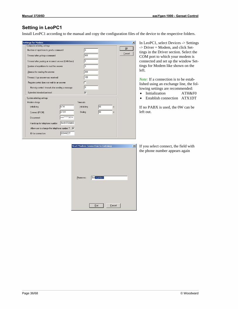
Setting in LeoPC1 Install LeoPC1 according to the manual and copy the configuration files of the device to the respective folders.
In LeoPC1, select Devices -> Settings -> Driver = Modem, and click Set-tings in the Driver section. Select the COM port to which your modem is connected and set up the window Set-tings for Modem like shown on the left.
Note: If a connection is to be estab-lished using an exchange line, the fol-lowing settings are recommended: • Initialization ATH&F0 • Establish connection ATX1DT If no PABX is used, the 0W can be left out.
If you select connect, the field with the phone number appears again
Manual 37205D easYgen-1000 - Genset Control
© Woodward Page 37/68
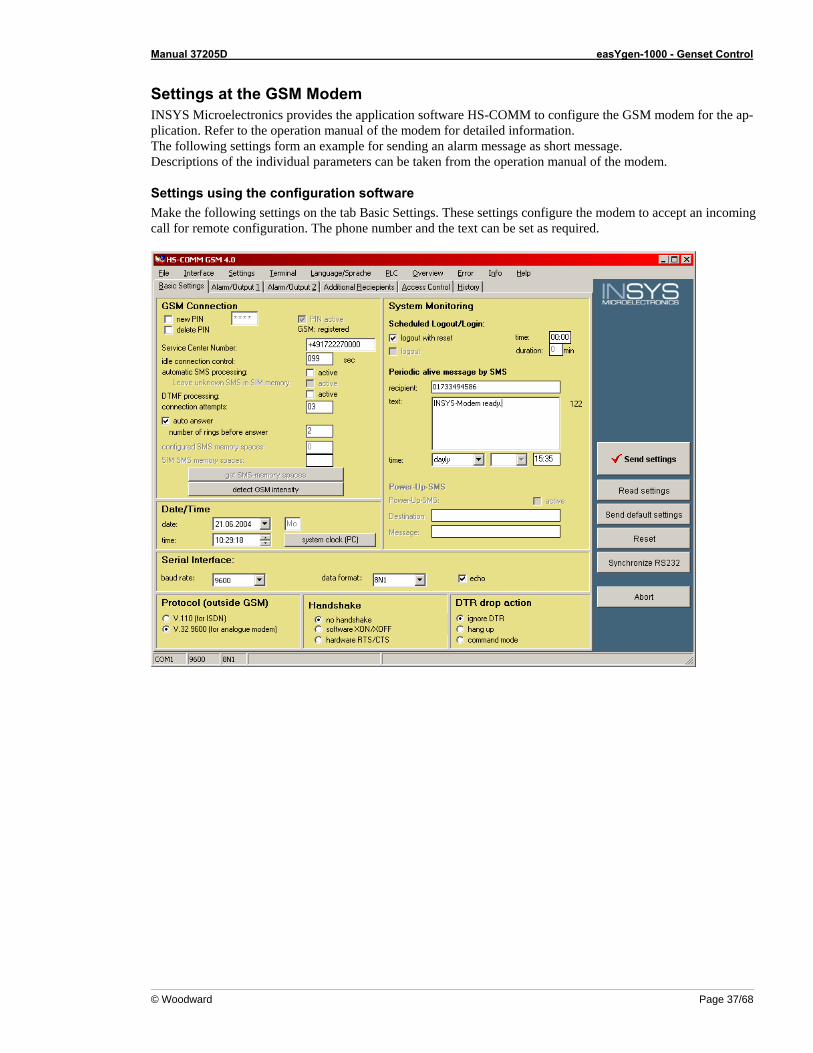
Settings at the GSM Modem INSYS Microelectronics provides the application software HS-COMM to configure the GSM modem for the ap-plication. Refer to the operation manual of the modem for detailed information. The following settings form an example for sending an alarm message as short message. Descriptions of the individual parameters can be taken from the operation manual of the modem.
Settings using the configuration software Make the following settings on the tab Basic Settings. These settings configure the modem to accept an incoming call for remote configuration. The phone number and the text can be set as required.
Manual 37205D easYgen-1000 - Genset Control
Page 38/68 © Woodward
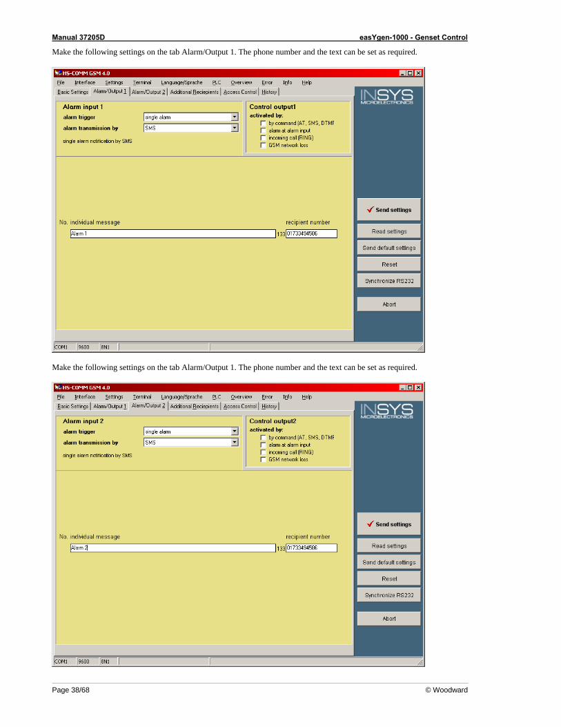
Make the following settings on the tab Alarm/Output 1. The phone number and the text can be set as required.
Make the following settings on the tab Alarm/Output 1. The phone number and the text can be set as required.

Manual 37205D easYgen-1000 - Genset Control
© Woodward Page 39/68
Connecting a Fixed-Network Modem ≡≡≡≡≡≡≡≡≡≡≡≡≡≡≡≡≡≡≡≡≡≡≡≡≡≡≡≡≡≡≡≡≡
Laptop with modemLaptop with modemwith Windows operation with Windows operation
systemsystem9x, NT, ME, 2000, XP9x, NT, ME, 2000, XP
LeoPC LeoPC configurationconfiguration and visualizationand visualization
e.g.e.g. Phoenix Phoenix landline Modemlandline Modem
withwith discrete input for dial updiscrete input for dial up
easYgen easYgen 15001500RJ45 socket edgewiseRJ45 socket edgewise
RS232RS232 RS232RS232
GalvanicGalvanicisolatedisolated
Configuration wireConfiguration wirewith galvanic isolation with galvanic isolation
(black box)(black box)DPCDPC--1 P/N 54171 P/N 5417--557557
Function It is possible to establish a phone connection to the system using a modem. This application is intended for sta-tionary use, where a steady remote control is required. It is also interesting to trigger a call in case of an alarm with this application. The Phoenix modem provides a dis-crete input for this, which can trigger e.g. a call or a fax message. Different actions can be performed 'online' using the application software LeoPC1, which is delivered on the CD-ROM with the product. These actions include:
• Configuration • Visualization with data logging • Remote control (start and stop via parameter "start in auto"; from V2.000 via remote control button "F") • Transfer standard values to and from the harddrive
Preconditions for this Example • easYgen-1000 • DPC-1 interface set (DPC-1 P/N 5417-557) • Phoenix PSI data/fax modem/RS232 (www.phoenixcontact.com) • Straight RS-232 cable SUB-D9/SUB-D9 (jack/jack) like Phoenix PSM-KA-9SUB9/BB/2METER • PC or notebook with Windows OS 9x, NT, ME, 2000, XP with external analog modem • Application software LeoPC1 version 3.1 or higher • Configuration files available (*.cfg, *.asm, *.opt, ...) • FAX/SMS receiver for receiving alarm messages
NOTE Sending an SMS via the fixed-network line may be enabled by the network provider.
NOTE The Phoenix PSI-Data/Fax-Modem/RS232 has one discrete input, which can be used to send an alarm message. One relay of the easYgen is required for the alarm message. It is also possible to use the switch output of the modem to operate a discrete input of the easYgen, for example for a remote start.
NOTE Using other modems. The easYgen does not send AT commands to the connected modem. The dispatch of an alarm mes-sage is performed by the modem after energizing a discrete input. If a different modem is used, this has to accept incoming calls automatically and establish a connec-tion between calling PC and easYgen.
Manual 37205D easYgen-1000 - Genset Control
Page 40/68 © Woodward
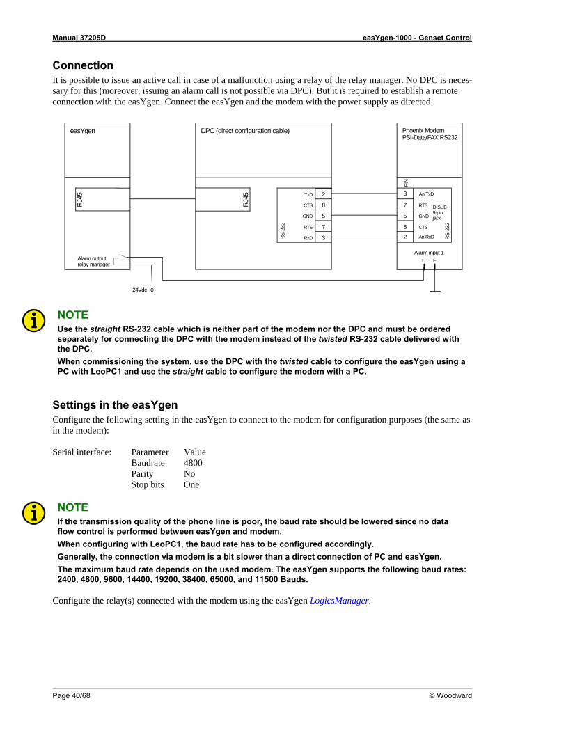
Connection It is possible to issue an active call in case of a malfunction using a relay of the relay manager. No DPC is neces-sary for this (moreover, issuing an alarm call is not possible via DPC). But it is required to establish a remote connection with the easYgen. Connect the easYgen and the modem with the power supply as directed.
24Vdc
RJ45
easYgen
RTS
GND
An RxD2
7
5
PIN
An TxD
CTS
RS-2
32
D-SUB9-pinjack
8
3
Phoenix ModemPSI-Data/FAX RS232
DPC (direct configuration cable)
CTS
GND
RxD
RTS
RS-2
32
5
7
3
TxD 2
8
Alarm outputrelay manager
i+ i-Alarm input 1
RJ45
NOTE Use the straight RS-232 cable which is neither part of the modem nor the DPC and must be ordered separately for connecting the DPC with the modem instead of the twisted RS-232 cable delivered with the DPC. When commissioning the system, use the DPC with the twisted cable to configure the easYgen using a PC with LeoPC1 and use the straight cable to configure the modem with a PC.
Settings in the easYgen Configure the following setting in the easYgen to connect to the modem for configuration purposes (the same as in the modem): Serial interface: Parameter Value Baudrate 4800 Parity No Stop bits One
NOTE If the transmission quality of the phone line is poor, the baud rate should be lowered since no data flow control is performed between easYgen and modem. When configuring with LeoPC1, the baud rate has to be configured accordingly. Generally, the connection via modem is a bit slower than a direct connection of PC and easYgen. The maximum baud rate depends on the used modem. The easYgen supports the following baud rates: 2400, 4800, 9600, 14400, 19200, 38400, 65000, and 11500 Bauds.
Configure the relay(s) connected with the modem using the easYgen LogicsManager.
Manual 37205D easYgen-1000 - Genset Control
© Woodward Page 41/68
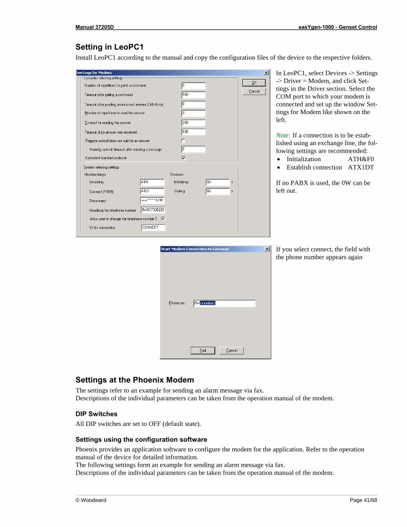
Setting in LeoPC1 Install LeoPC1 according to the manual and copy the configuration files of the device to the respective folders.
In LeoPC1, select Devices -> Settings -> Driver = Modem, and click Set-tings in the Driver section. Select the COM port to which your modem is connected and set up the window Set-tings for Modem like shown on the left.
Note: If a connection is to be estab-lished using an exchange line, the fol-lowing settings are recommended: • Initialization ATH&F0 • Establish connection ATX1DT If no PABX is used, the 0W can be left out.
If you select connect, the field with the phone number appears again
Settings at the Phoenix Modem The settings refer to an example for sending an alarm message via fax. Descriptions of the individual parameters can be taken from the operation manual of the modem.
DIP Switches All DIP switches are set to OFF (default state).
Settings using the configuration software Phoenix provides an application software to configure the modem for the application. Refer to the operation manual of the device for detailed information. The following settings form an example for sending an alarm message via fax. Descriptions of the individual parameters can be taken from the operation manual of the modem.
Manual 37205D easYgen-1000 - Genset Control
Page 42/68 © Woodward
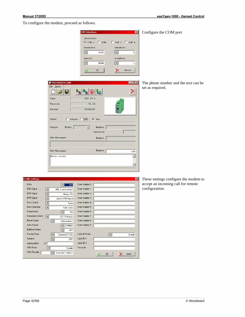
To configure the modem, proceed as follows.
Configure the COM port
The phone number and the text can be set as required.
These settings configure the modem to accept an incoming call for remote configuration.
Manual 37205D easYgen-1000 - Genset Control
© Woodward Page 43/68
Chapter 6. Connecting External Components
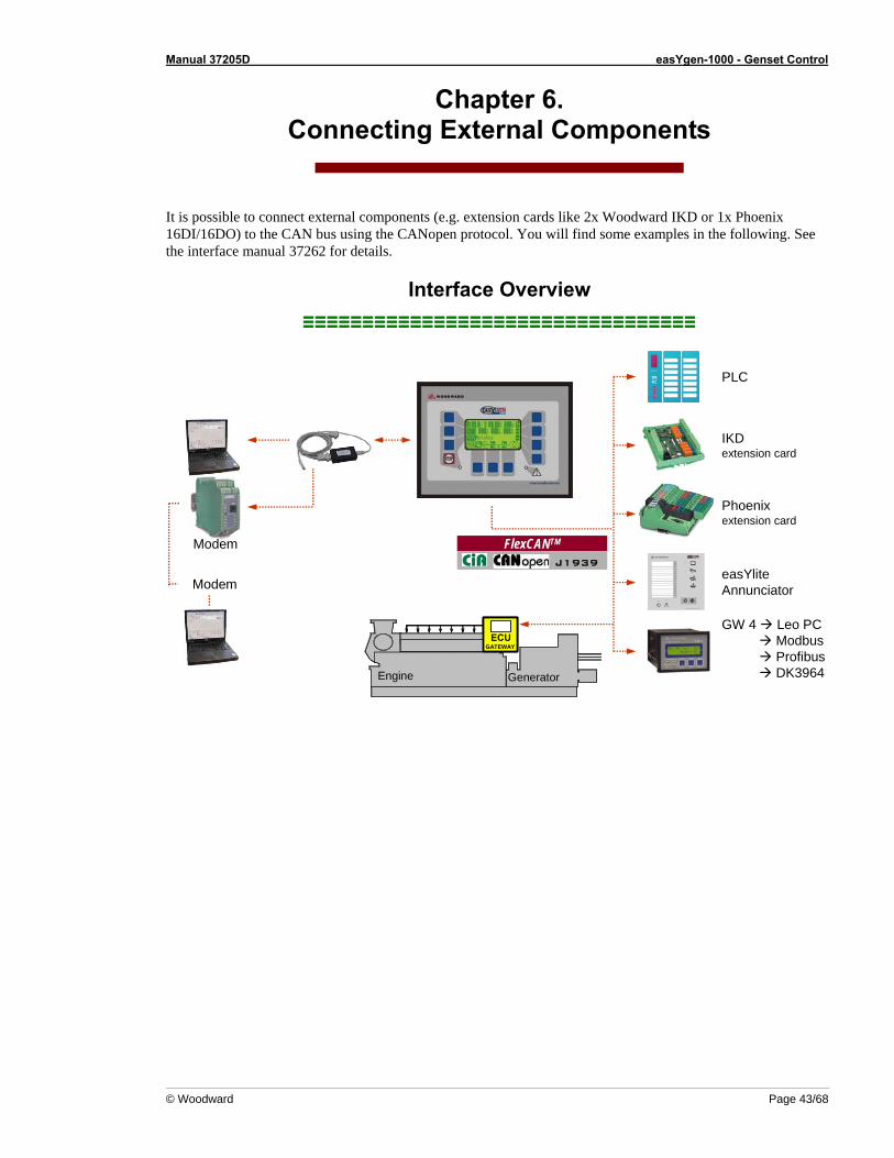
It is possible to connect external components (e.g. extension cards like 2x Woodward IKD or 1x Phoenix 16DI/16DO) to the CAN bus using the CANopen protocol. You will find some examples in the following. See the interface manual 37262 for details.
Interface Overview ≡≡≡≡≡≡≡≡≡≡≡≡≡≡≡≡≡≡≡≡≡≡≡≡≡≡≡≡≡≡≡≡≡
ENGINE GENERATOR
ECUGATEWAY
Engine Generator
ECUGATEWAY
ENGINE GENERATOR
ECUGATEWAY
Engine Generator
ECUGATEWAY
IKD extension card
Phoenix extension card
easYliteAnnunciator
GW 4 Leo PCModbusProfibusDK3964
PLC
FlexCANTM
J1939
FlexCANTM
J1939
Modem
Modem
Manual 37205D easYgen-1000 - Genset Control
Page 44/68 © Woodward
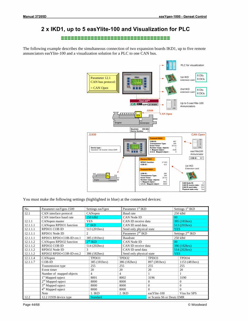
2 x IKD1, up to 5 easYlite-100 and Visualization for PLC ≡≡≡≡≡≡≡≡≡≡≡≡≡≡≡≡≡≡≡≡≡≡≡≡≡≡≡≡≡≡≡≡≡
The following example describes the simultaneous connection of two expansion boards IKD1, up to five remote annunciators easYlite-100 and a visualization solution for a PLC to one CAN bus.
ENGINE GENERATOR
ECUGATEWAY
Engine Generator
ECUGATEWAY
ENGINE GENERATOR
ECUGATEWAY
Engine Generator
ECUGATEWAY
1st IKD extension card
Up to 5 easYlite-100Annunciators
PLC for visualization
FlexCANTM
J1939
FlexCANTM
J1939
2nd IKD extension card
Parameter 12.1 CAN bus protocol:
= CAN Open
8 DIs 8 DOs
8 Dis8 DOs
J1939CAN Open
1st IKD Extension card
ENGINE GENERATOR
ECUGATEWAY
Engine Generator
ECUGATEWAY
easYlite100Annunciator
J1939J1939 CAN OpenCAN Open
Receive PDO1 :
CAN Node ID:CAN Node ID: 0 CAN ID receive data : CAN ID receive data : 385CAN ID send data : CAN ID send data : 513Physical state only:Physical state only: Yes
COB ID :COB ID : 513
Transmit PDO1 :
COB ID :COB ID : 385 Transmission Type:Transmission Type: 255Event Timer:Event Timer: 20 msNumber Number mappmapp. objects: . objects: 41. Mapped object : 1. Mapped object : 80012./3./4. Mapped object : 2./3./4. Mapped object : 8000
RPDO1 functionRPDO1 function: 1st IKD
COB ID :COB ID : 897 Transmission Type:Transmission Type: 255Event Timer:Event Timer: 20 msNumberNumber mappmapp. objects: . objects: 11. Mapped object : 1. Mapped object : 31962./3./4. Mapped object : 2./3./4. Mapped object : 0
Device type :Device type :Standard / S6 Scania / Deutz EMR
Transmit PDO3 :
BaudrateBaudrate: 250 : 250 kBdkBdDevice Number 1Device Number 1
COB ID :COB ID : 897
You must make the following settings (highlighted in blue) at the connected devices: No. Parameter easYgen-1500 Settings easYgen Parameter 1st IKD Settings 1st IKD 12.1 CAN interface protocol CANopen Baud rate 250 kBd CAN interface baud rate 250 kBd CAN Node ID 00 12.1.1 CANopen master YES CAN ID receive data 385 (181hex) 12.1.1.1 CANopen RPDO1 function 1st IKD CAN ID send data 513 (201hex) 12.1.1.1 RPDO1 COB ID 513 (201hex) Send only physical state YES 12.1.1.1 RPDO1 Node ID 2 Parameter 2nd IKD Settings 2nd IKD 12.1.1.1 RPDO1 RPDO-COB-ID ext.1 385 (181hex) Baudrate 250 kBd 12.1.1.2 CANopen RPDO2 function 2nd IKD CAN Node ID 00 12.1.1.2 RPDO2 COB ID 514 (202hex) CAN ID receive data 386 (182hex) 12.1.1.2 RPDO2 Node ID 3 CAN ID send data 514 (202hex) 12.1.1.2 RPDO2 RPDO-COB-ID ext.2 386 (182hex) Send only physical state YES 12.1.1.4 CANopen TPDO1 TPDO2 TPDO3 TPDO4 12.1.1.7 COB-ID 385 (181hex) 386 (182hex) 897 (381hex) 1153 (481hex) Transmission type 255 255 255 255 Event timer 20 20 20 20 Number of mapped objects 4 4 1 1 1st Mapped opject 8001 8002 3196 3190 2nd Mapped opject 8000 8000 0 0 3rd Mapped opject 8000 8000 0 0 4th Mapped opject 8000 8000 0 0 Note 1. IKD 2. IKD easYlite-100 Visu for SPS 12.2 12.2 J1939 device type Standard or Scania S6 or Deutz EMR
Manual 37205D easYgen-1000 - Genset Control
© Woodward Page 45/68
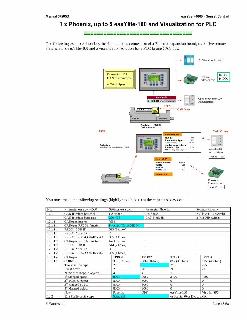
1 x Phoenix, up to 5 easYlite-100 and Visualization for PLC ≡≡≡≡≡≡≡≡≡≡≡≡≡≡≡≡≡≡≡≡≡≡≡≡≡≡≡≡≡≡≡≡≡
The following example describes the simultaneous connection of a Phoenix expansion board, up to five remote annunciators easYlite-100 and a visualization solution for a PLC to one CAN bus.
ENGINE GENERATOR
ECUGATEWAY
Engine Generator
ECUGATEWAY
ENGINE GENERATOR
ECUGATEWAY
Engine Generator
ECUGATEWAY
Up to 5 easYlite-100Annunciators
PLC for visualization
FlexCANTM
J1939
FlexCANTM
J1939
Parameter 12.1 CAN bus protocol:
= CAN Open
Phoenix extension card
16 Dis16 DOs
CAN OpenJ1939
ENGINE GENERATOR
ECUGATEWAY
Engine Generator
ECUGATEWAY
easYlite100Annunciator
J1939J1939 CAN OpenCAN Open
Receive PDO1 :
Node ID : Node ID : 2
Node ID:Node ID: 2COB ID ext. : COB ID ext. : 385
Transmit PDO1 :
RPDO1 functionRPDO1 function: Phoenix
COB ID :COB ID : 897 Transmission Type:Transmission Type: 255Event Timer:Event Timer: 20 msNumberNumber mappmapp. objects: . objects: 11. Mapped object : 1. Mapped object : 31962./3./4. Mapped object : 2./3./4. Mapped object : 0
Device type :Device type :Standard / S6 Scania / Deutz EMR
Transmit PDO3 :
Phoenix Extension card
COB ID :COB ID : 513
COB ID :COB ID : 897
BaudrateBaudrate: 250 : 250 kBdkBdDevice Number 1Device Number 1
You must make the following settings (highlighted in blue) at the connected devices: No. Parameter easYgen-1500 Settings easYgen Parameter Phoenix Settings Phoenix 12.1 CAN interface protocol CANopen Baud rate 250 kBd (DIP switch) CAN interface baud rate 250 kBd CAN Node ID 2 (via DIP switch) 12.1.1 CANopen master YES 12.1.1.1 CANopen RPDO1 function Phoenix "Co 16DIDO" 12.1.1.1 RPDO1 COB ID 513 (201hex) 12.1.1.1 RPDO1 Node ID 2 12.1.1.1 RPDO1 RPDO-COB-ID ext.1 385 (181hex) 12.1.1.2 CANopen RPDO2 function No function 12.1.1.2 RPDO2 COB ID 514 (202hex) 12.1.1.2 RPDO2 Node ID 3 12.1.1.2 RPDO2 RPDO-COB-ID ext.2 386 (182hex) 12.1.1.4 CANopen TPDO1 TPDO2 TPDO3 TPDO4 12.1.1.7 COB-ID 385 (181hex) 386 (182hex) 897 (381hex) 1153 (481hex) Transmission type 255 0 255 255 Event timer 20 20 20 20 Number of mapped objects 4 4 1 1 1st Mapped opject 8003 8002 3196 3190 2nd Mapped opject 8000 8000 0 0 3rd Mapped opject 8000 8000 0 0 4th Mapped opject 8000 8000 0 0 Note Phoenix OFF easYlite-100 Visu for SPS 12.2 12.2 J1939 device type Standard or Scania S6 or Deutz EMR
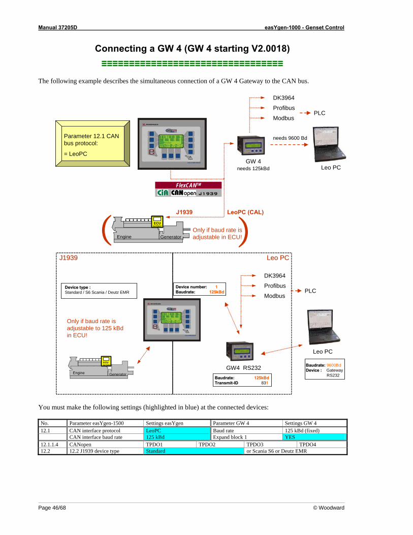
Manual 37205D easYgen-1000 - Genset Control
Page 46/68 © Woodward
Connecting a GW 4 (GW 4 starting V2.0018) ≡≡≡≡≡≡≡≡≡≡≡≡≡≡≡≡≡≡≡≡≡≡≡≡≡≡≡≡≡≡≡≡≡
The following example describes the simultaneous connection of a GW 4 Gateway to the CAN bus.
ENGINE GENERATOR
ECUGATEWAY
Engine Generator
ECUGATEWAY
ENGINE GENERATOR
ECUGATEWAY
Engine Generator
ECUGATEWAY
FlexCANTM
J1939
FlexCANTM
J1939
GW 4
Parameter 12.1 CAN bus protocol:
= LeoPC
LeoPC (CAL)J1939
Only if baud rate is adjustable in ECU!( )
Leo PCneeds 125kBd
needs 9600 Bd
DK3964
Profibus
ModbusPLC
ENGINE GENERATOR
ECUGATEWAY
Engine Generator
ECUGATEWAY
J1939J1939 Leo PCLeo PC
BaudrateBaudrate:: 125kBd125kBdTransmitTransmit--IDID 831
Device type :Device type :Standard / S6 Scania / Deutz EMR
GW4 RS232
Device number:Device number: 1BaudrateBaudrate: : 125kBd125kBd
Leo PC
BaudrateBaudrate:: 9600BdDevice :Device : Gateway
RS232
Only if baud rate is adjustable to 125 kBdin ECU!
DK3964
Profibus
ModbusPLC
You must make the following settings (highlighted in blue) at the connected devices: No. Parameter easYgen-1500 Settings easYgen Parameter GW 4 Settings GW 4 12.1 CAN interface protocol LeoPC Baud rate 125 kBd (fixed) CAN interface baud rate 125 kBd Expand block 1 YES 12.1.1.4 CANopen TPDO1 TPDO2 TPDO3 TPDO4 12.2 12.2 J1939 device type Standard or Scania S6 or Deutz EMR
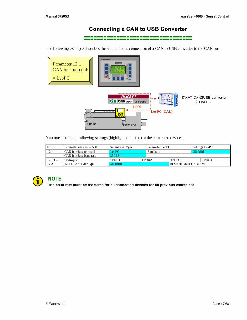
Manual 37205D easYgen-1000 - Genset Control
© Woodward Page 47/68
Connecting a CAN to USB Converter ≡≡≡≡≡≡≡≡≡≡≡≡≡≡≡≡≡≡≡≡≡≡≡≡≡≡≡≡≡≡≡≡≡
The following example describes the simultaneous connection of a CAN to USB converter to the CAN bus.
ENGINE GENERATOR
ECUGATEWAY
Engine Generator
ECUGATEWAY
ENGINE GENERATOR
ECUGATEWAY
Engine Generator
ECUGATEWAY
FlexCANTM
J1939
FlexCANTM
J1939
Parameter 12.1 CAN bus protocol:
= LeoPC
IXXAT CAN2USB converterLeo PC
LeoPC (CAL)J1939
You must make the following settings (highlighted in blue) at the connected devices: No. Parameter easYgen-1500 Settings easYgen Parameter LeoPC1 Settings LeoPC1 12.1 CAN interface protocol LeoPC Baud rate 250 kBd CAN interface baud rate 250 kBd 12.1.1.4 CANopen TPDO1 TPDO2 TPDO3 TPDO4 12.2 12.2 J1939 device type Standard or Scania S6 or Deutz EMR
NOTE The baud rate must be the same for all connected devices for all previous examples!
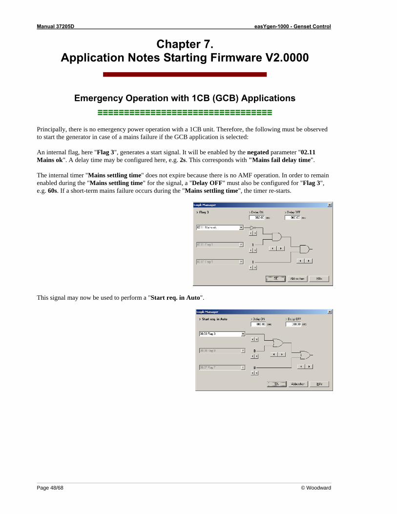
Manual 37205D easYgen-1000 - Genset Control
Page 48/68 © Woodward
Chapter 7. Application Notes Starting Firmware V2.0000
Emergency Operation with 1CB (GCB) Applications ≡≡≡≡≡≡≡≡≡≡≡≡≡≡≡≡≡≡≡≡≡≡≡≡≡≡≡≡≡≡≡≡≡
Principally, there is no emergency power operation with a 1CB unit. Therefore, the following must be observed to start the generator in case of a mains failure if the GCB application is selected: An internal flag, here "Flag 3", generates a start signal. It will be enabled by the negated parameter "02.11 Mains ok". A delay time may be configured here, e.g. 2s. This corresponds with "Mains fail delay time". The internal timer "Mains settling time" does not expire because there is no AMF operation. In order to remain enabled during the "Mains settling time" for the signal, a "Delay OFF" must also be configured for "Flag 3", e.g. 60s. If a short-term mains failure occurs during the "Mains settling time", the timer re-starts.
This signal may now be used to perform a "Start req. in Auto".
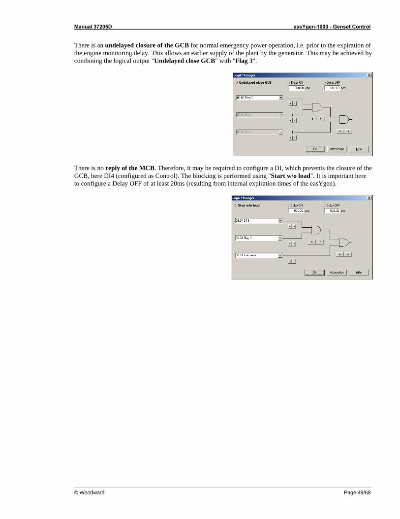
Manual 37205D easYgen-1000 - Genset Control
© Woodward Page 49/68
There is an undelayed closure of the GCB for normal emergency power operation, i.e. prior to the expiration of the engine monitoring delay. This allows an earlier supply of the plant by the generator. This may be achieved by combining the logical output "Undelayed close GCB" with "Flag 3".
There is no reply of the MCB. Therefore, it may be required to configure a DI, which prevents the closure of the GCB, here DI4 (configured as Control). The blocking is performed using "Start w/o load". It is important here to configure a Delay OFF of at least 20ms (resulting from internal expiration times of the easYgen).
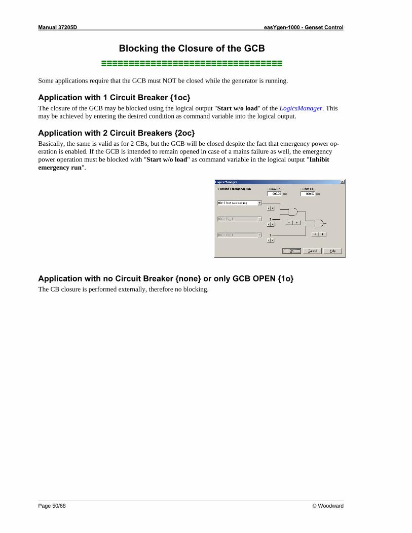
Manual 37205D easYgen-1000 - Genset Control
Page 50/68 © Woodward
Blocking the Closure of the GCB ≡≡≡≡≡≡≡≡≡≡≡≡≡≡≡≡≡≡≡≡≡≡≡≡≡≡≡≡≡≡≡≡≡
Some applications require that the GCB must NOT be closed while the generator is running.
Application with 1 Circuit Breaker {1oc} The closure of the GCB may be blocked using the logical output "Start w/o load" of the LogicsManager. This may be achieved by entering the desired condition as command variable into the logical output.
Application with 2 Circuit Breakers {2oc} Basically, the same is valid as for 2 CBs, but the GCB will be closed despite the fact that emergency power op-eration is enabled. If the GCB is intended to remain opened in case of a mains failure as well, the emergency power operation must be blocked with "Start w/o load" as command variable in the logical output "Inhibit emergency run".
Application with no Circuit Breaker {none} or only GCB OPEN {1o} The CB closure is performed externally, therefore no blocking.
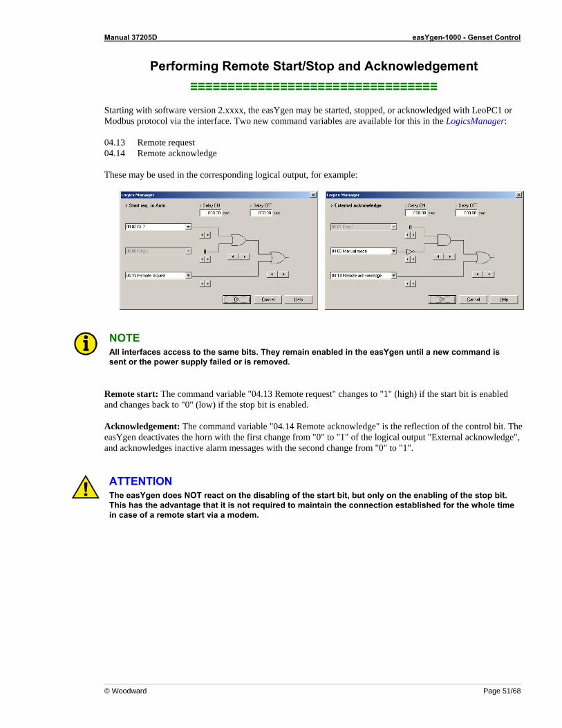
Manual 37205D easYgen-1000 - Genset Control
© Woodward Page 51/68
Performing Remote Start/Stop and Acknowledgement ≡≡≡≡≡≡≡≡≡≡≡≡≡≡≡≡≡≡≡≡≡≡≡≡≡≡≡≡≡≡≡≡≡
Starting with software version 2.xxxx, the easYgen may be started, stopped, or acknowledged with LeoPC1 or Modbus protocol via the interface. Two new command variables are available for this in the LogicsManager: 04.13 Remote request 04.14 Remote acknowledge These may be used in the corresponding logical output, for example:
NOTE All interfaces access to the same bits. They remain enabled in the easYgen until a new command is sent or the power supply failed or is removed.
Remote start: The command variable "04.13 Remote request" changes to "1" (high) if the start bit is enabled and changes back to "0" (low) if the stop bit is enabled. Acknowledgement: The command variable "04.14 Remote acknowledge" is the reflection of the control bit. The easYgen deactivates the horn with the first change from "0" to "1" of the logical output "External acknowledge", and acknowledges inactive alarm messages with the second change from "0" to "1".
ATTENTION The easYgen does NOT react on the disabling of the start bit, but only on the enabling of the stop bit. This has the advantage that it is not required to maintain the connection established for the whole time in case of a remote start via a modem.
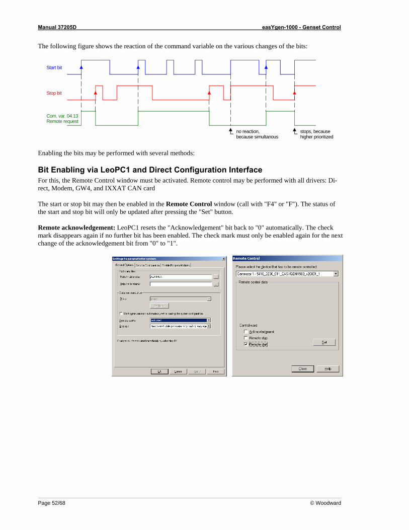
Manual 37205D easYgen-1000 - Genset Control
Page 52/68 © Woodward
The following figure shows the reaction of the command variable on the various changes of the bits:
stops, becausehigher prioritized
Start bit
Stop bit
Com. var. 04.13Remote request
no reaction,because simultanous
Enabling the bits may be performed with several methods:
Bit Enabling via LeoPC1 and Direct Configuration Interface For this, the Remote Control window must be activated. Remote control may be performed with all drivers: Di-rect, Modem, GW4, and IXXAT CAN card The start or stop bit may then be enabled in the Remote Control window (call with "F4" or "F"). The status of the start and stop bit will only be updated after pressing the "Set" button. Remote acknowledgement: LeoPC1 resets the "Acknowledgement" bit back to "0" automatically. The check mark disappears again if no further bit has been enabled. The check mark must only be enabled again for the next change of the acknowledgement bit from "0" to "1".
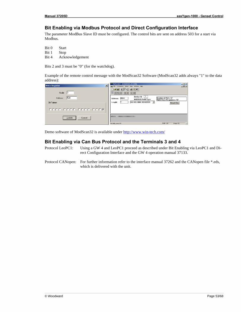
Manual 37205D easYgen-1000 - Genset Control
© Woodward Page 53/68
Bit Enabling via Modbus Protocol and Direct Configuration Interface The parameter ModBus Slave ID must be configured. The control bits are sent on address 503 for a start via Modbus. Bit 0 Start Bit 1 Stop Bit 4 Acknowledgement Bits 2 and 3 must be "0" (for the watchdog). Example of the remote control message with the ModScan32 Software (ModScan32 adds always "1" to the data address):
Demo software of ModScan32 is available under http://www.win-tech.com/
Bit Enabling via Can Bus Protocol and the Terminals 3 and 4 Protocol LeoPC1: Using a GW 4 and LeoPC1 proceed as described under Bit Enabling via LeoPC1 and Di-
rect Configuration Interface and the GW 4 operation manual 37133. Protocol CANopen: For further information refer to the interface manual 37262 and the CANopen file *.eds,
which is delivered with the unit.
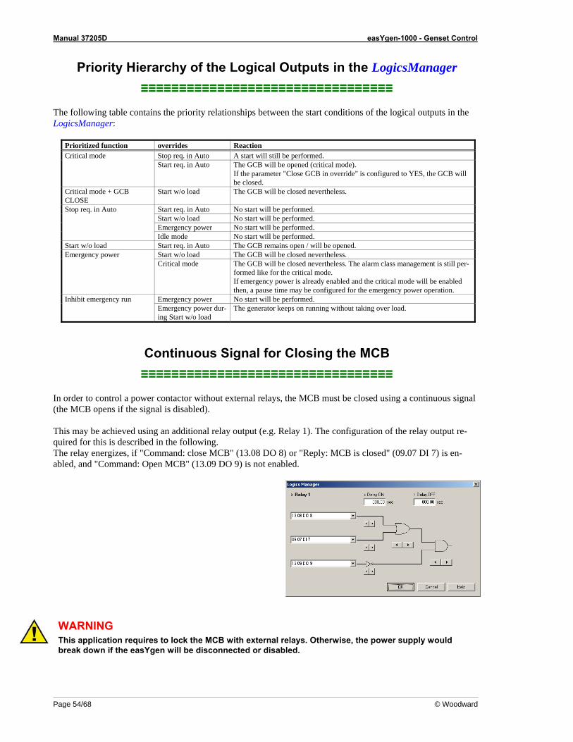
Manual 37205D easYgen-1000 - Genset Control
Page 54/68 © Woodward
Priority Hierarchy of the Logical Outputs in the LogicsManager ≡≡≡≡≡≡≡≡≡≡≡≡≡≡≡≡≡≡≡≡≡≡≡≡≡≡≡≡≡≡≡≡≡
The following table contains the priority relationships between the start conditions of the logical outputs in the LogicsManager:
Prioritized function overrides Reaction Stop req. in Auto A start will still be performed. Critical mode Start req. in Auto The GCB will be opened (critical mode).
If the parameter "Close GCB in override" is configured to YES, the GCB will be closed.
Critical mode + GCB CLOSE
Start w/o load The GCB will be closed nevertheless.
Start req. in Auto No start will be performed. Start w/o load No start will be performed. Emergency power No start will be performed.
Stop req. in Auto
Idle mode No start will be performed. Start w/o load Start req. in Auto The GCB remains open / will be opened.
Start w/o load The GCB will be closed nevertheless. Emergency power Critical mode The GCB will be closed nevertheless. The alarm class management is still per-
formed like for the critical mode. If emergency power is already enabled and the critical mode will be enabled then, a pause time may be configured for the emergency power operation.
Emergency power No start will be performed. Inhibit emergency run Emergency power dur-ing Start w/o load
The generator keeps on running without taking over load.
Continuous Signal for Closing the MCB ≡≡≡≡≡≡≡≡≡≡≡≡≡≡≡≡≡≡≡≡≡≡≡≡≡≡≡≡≡≡≡≡≡
In order to control a power contactor without external relays, the MCB must be closed using a continuous signal (the MCB opens if the signal is disabled). This may be achieved using an additional relay output (e.g. Relay 1). The configuration of the relay output re-quired for this is described in the following. The relay energizes, if "Command: close MCB" (13.08 DO 8) or "Reply: MCB is closed" (09.07 DI 7) is en-abled, and "Command: Open MCB" (13.09 DO 9) is not enabled.
WARNING This application requires to lock the MCB with external relays. Otherwise, the power supply would break down if the easYgen will be disconnected or disabled.
Manual 37205D easYgen-1000 - Genset Control
© Woodward Page 55/68
Using External DOs as Additional LogicsManager Flags ≡≡≡≡≡≡≡≡≡≡≡≡≡≡≡≡≡≡≡≡≡≡≡≡≡≡≡≡≡≡≡≡≡
8 internal flags are available for working with the LogicsManager. These flags may be used as 'auxiliary flags'. Auxiliary flags may always be used whenever the possible configuration of 3 command variables is not suffi-cient. In this case, you are able to configure the remaining command variables to the output of the auxiliary flag and use this as command variable (00.01 - 00.08) again. For all applications, which require more than 8 flags, the LogicsManager outputs of the external discrete outputs may be used as auxiliary flags from version 2.0000 on – however, this is only possible if no external expansion boards are connected, otherwise the relays of this boards would energize accidental with activating these flags. This enables to use another 16 auxiliary flags with the command variables 14.01 - 14.16.
Additional Flexible Limits ≡≡≡≡≡≡≡≡≡≡≡≡≡≡≡≡≡≡≡≡≡≡≡≡≡≡≡≡≡≡≡≡≡
The analog inputs are now equipped with 4 new 'flexible limits'. These limits may be used if the existing 2 limits per analog input are not sufficient anymore, e.g. if a warning, a stopping, and an additional limit is required for control purposes (coolant heating). In addition, they may be used to monitor the analog inputs of an ECU, which is connected via the CAN bus. Apart from that, the values on the ECU are only read out by the easYgen-1500 and no reaction will take place. The flexible limits offer the full functionality of other monitoring functions, too. Either a shutdown or a control function may be performed, which may be configured using the alarm class. If an alarm class is selected, a freely configurable text entry will be written to the event recorder. The flexible limits may react on the following inputs: Analog In1 analog input 1, directly connected with the unit, terminals 13 / 12 Analog In2 analog input 2, directly connected with the unit, terminals 11 / 12 ECU SPN 110 coolant temperature from the ECU, via CAN, terminals 3 / 4 connected ECU SPN 100 oil pressure from the ECU, via CAN, terminals 3 / 4 connected ECU SPN 190 speed from the ECU, via CAN, terminals 3 / 4 connected The alarm class and the associated text may also be configured. The setting ranges are described in detail in the configuration manual 37204 under Analog Inputs: Configure Flexible Thresholds.
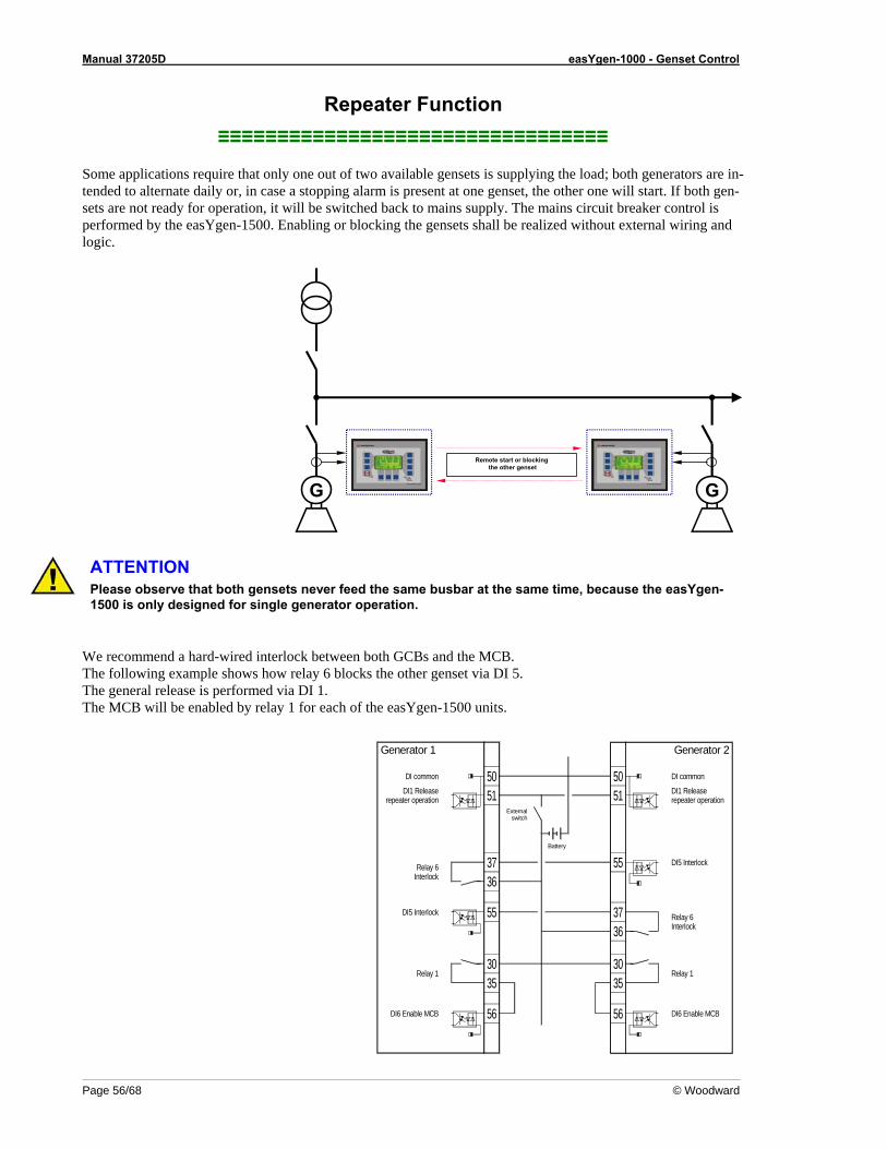
Manual 37205D easYgen-1000 - Genset Control
Page 56/68 © Woodward
Repeater Function ≡≡≡≡≡≡≡≡≡≡≡≡≡≡≡≡≡≡≡≡≡≡≡≡≡≡≡≡≡≡≡≡≡
Some applications require that only one out of two available gensets is supplying the load; both generators are in-tended to alternate daily or, in case a stopping alarm is present at one genset, the other one will start. If both gen-sets are not ready for operation, it will be switched back to mains supply. The mains circuit breaker control is performed by the easYgen-1500. Enabling or blocking the gensets shall be realized without external wiring and logic.
G G
Remote start or blockingthe other genset
ATTENTION Please observe that both gensets never feed the same busbar at the same time, because the easYgen-1500 is only designed for single generator operation.
We recommend a hard-wired interlock between both GCBs and the MCB. The following example shows how relay 6 blocks the other genset via DI 5. The general release is performed via DI 1. The MCB will be enabled by relay 1 for each of the easYgen-1500 units.
3637
5150
5150
55
363755
3530
56
3530
56
Battery
Externalswitch
DI commonDI common
DI1 Releaserepeater operation
DI1 Releaserepeater operation
DI5 InterlockRelay 6Interlock
DI5 Interlock Relay 6Interlock
Relay 1Relay 1
DI6 Enable MCBDI6 Enable MCB
Generator 1 Generator 2
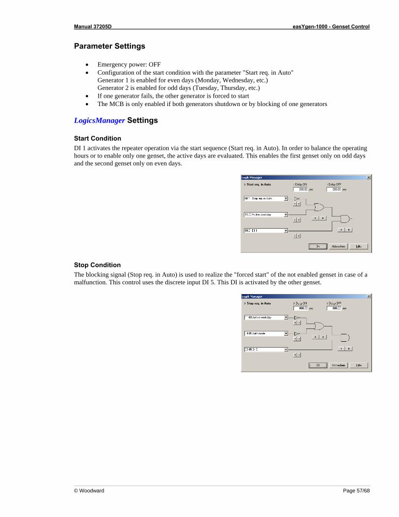
Manual 37205D easYgen-1000 - Genset Control
© Woodward Page 57/68
Parameter Settings
• Emergency power: OFF • Configuration of the start condition with the parameter "Start req. in Auto"
Generator 1 is enabled for even days (Monday, Wednesday, etc.) Generator 2 is enabled for odd days (Tuesday, Thursday, etc.)
• If one generator fails, the other generator is forced to start • The MCB is only enabled if both generators shutdown or by blocking of one generators
LogicsManager Settings
Start Condition DI 1 activates the repeater operation via the start sequence (Start req. in Auto). In order to balance the operating hours or to enable only one genset, the active days are evaluated. This enables the first genset only on odd days and the second genset only on even days.
Stop Condition The blocking signal (Stop req. in Auto) is used to realize the "forced start" of the not enabled genset in case of a malfunction. This control uses the discrete input DI 5. This DI is activated by the other genset.
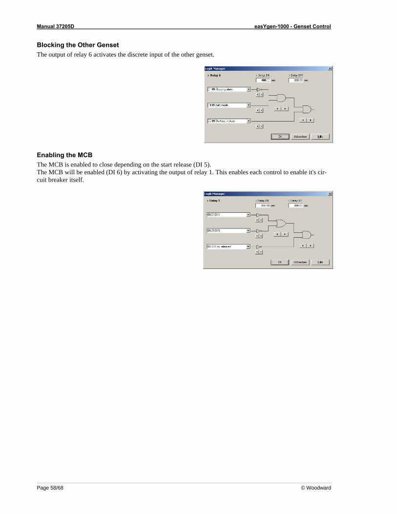
Manual 37205D easYgen-1000 - Genset Control
Page 58/68 © Woodward
Blocking the Other Genset The output of relay 6 activates the discrete input of the other genset.
Enabling the MCB The MCB is enabled to close depending on the start release (DI 5). The MCB will be enabled (DI 6) by activating the output of relay 1. This enables each control to enable it's cir-cuit breaker itself.
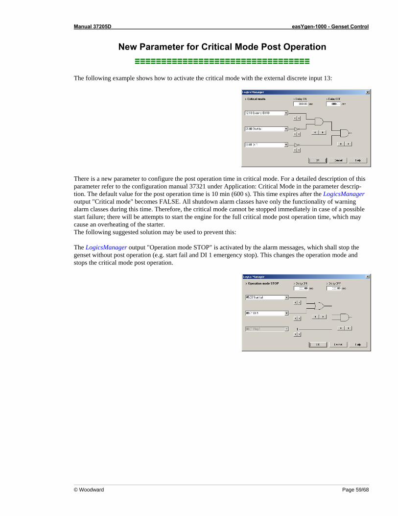
Manual 37205D easYgen-1000 - Genset Control
© Woodward Page 59/68
New Parameter for Critical Mode Post Operation ≡≡≡≡≡≡≡≡≡≡≡≡≡≡≡≡≡≡≡≡≡≡≡≡≡≡≡≡≡≡≡≡≡
The following example shows how to activate the critical mode with the external discrete input 13:
There is a new parameter to configure the post operation time in critical mode. For a detailed description of this parameter refer to the configuration manual 37321 under Application: Critical Mode in the parameter descrip-tion. The default value for the post operation time is 10 min (600 s). This time expires after the LogicsManager output "Critical mode" becomes FALSE. All shutdown alarm classes have only the functionality of warning alarm classes during this time. Therefore, the critical mode cannot be stopped immediately in case of a possible start failure; there will be attempts to start the engine for the full critical mode post operation time, which may cause an overheating of the starter. The following suggested solution may be used to prevent this: The LogicsManager output "Operation mode STOP" is activated by the alarm messages, which shall stop the genset without post operation (e.g. start fail and DI 1 emergency stop). This changes the operation mode and stops the critical mode post operation.
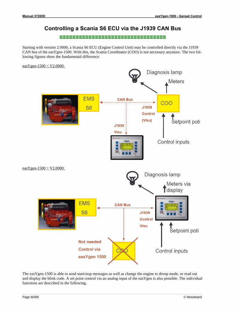
Manual 37205D easYgen-1000 - Genset Control
Page 60/68 © Woodward
Controlling a Scania S6 ECU via the J1939 CAN Bus ≡≡≡≡≡≡≡≡≡≡≡≡≡≡≡≡≡≡≡≡≡≡≡≡≡≡≡≡≡≡≡≡≡
Starting with version 2.0000, a Scania S6 ECU (Engine Control Unit) may be controlled directly via the J1939 CAN bus of the easYgen-1500. With this, the Scania Coordinator (COO) is not necessary anymore. The two fol-lowing figures show the fundamental difference: easYgen-1500 < V2.0000:
easYgen-1500 > V2.0000:
The easYgen-1500 is able to send start/stop messages as well as change the engine to droop mode, or read out and display the blink code. A set point control via an analog input of the easYgen is also possible. The individual functions are described in the following.
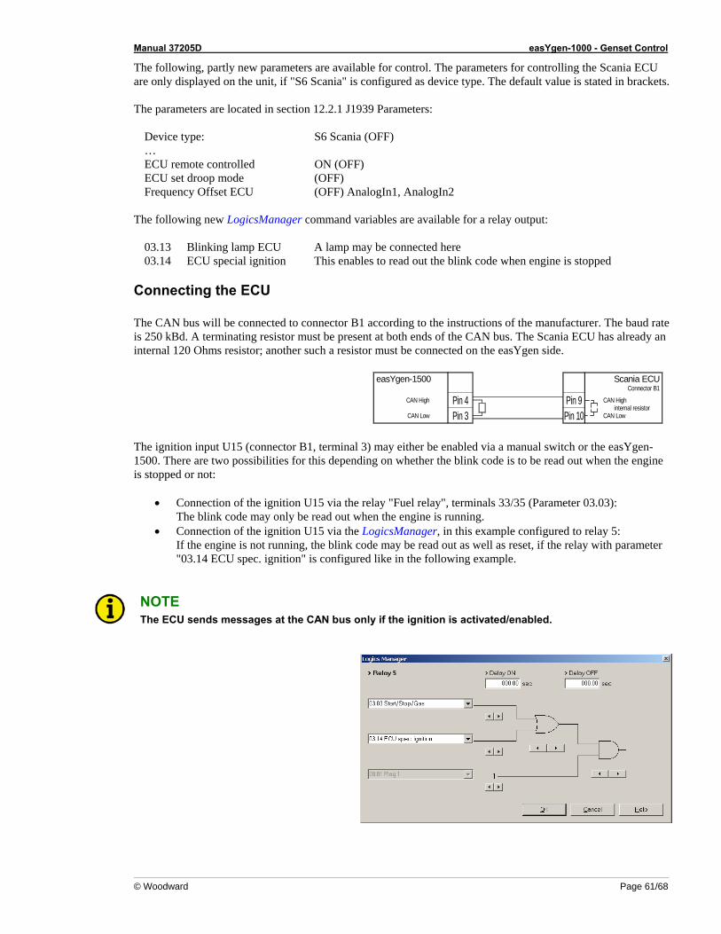
Manual 37205D easYgen-1000 - Genset Control
© Woodward Page 61/68
The following, partly new parameters are available for control. The parameters for controlling the Scania ECU are only displayed on the unit, if "S6 Scania" is configured as device type. The default value is stated in brackets. The parameters are located in section 12.2.1 J1939 Parameters:
Device type: S6 Scania (OFF) … ECU remote controlled ON (OFF) ECU set droop mode (OFF) Frequency Offset ECU (OFF) AnalogIn1, AnalogIn2
The following new LogicsManager command variables are available for a relay output:
03.13 Blinking lamp ECU A lamp may be connected here 03.14 ECU special ignition This enables to read out the blink code when engine is stopped
Connecting the ECU The CAN bus will be connected to connector B1 according to the instructions of the manufacturer. The baud rate is 250 kBd. A terminating resistor must be present at both ends of the CAN bus. The Scania ECU has already an internal 120 Ohms resistor; another such a resistor must be connected on the easYgen side.
Pin 3Pin 4
Pin 10Pin 9
internal resistorCAN High
CAN Low
easYgen-1500 Scania ECUConnector B1
CAN High
CAN Low The ignition input U15 (connector B1, terminal 3) may either be enabled via a manual switch or the easYgen-1500. There are two possibilities for this depending on whether the blink code is to be read out when the engine is stopped or not:
• Connection of the ignition U15 via the relay "Fuel relay", terminals 33/35 (Parameter 03.03): The blink code may only be read out when the engine is running.
• Connection of the ignition U15 via the LogicsManager, in this example configured to relay 5: If the engine is not running, the blink code may be read out as well as reset, if the relay with parameter "03.14 ECU spec. ignition" is configured like in the following example.
NOTE The ECU sends messages at the CAN bus only if the ignition is activated/enabled.
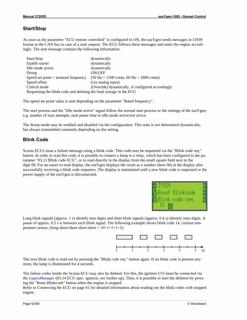
Manual 37205D easYgen-1000 - Genset Control
Page 62/68 © Woodward
Start/Stop As soon as the parameter "ECU remote controlled" is configured to ON, the easYgen sends messages in J1939 format at the CAN bus in case of a start request. The ECU follows these messages and starts the engine accord-ingly. The sent message contains the following information:
Start/Stop dynamically Enable starter dynamically Idle mode active dynamically Droop ON/OFF Speed set point = nominal frequency (50 Hz = 1500 r/min, 60 Hz = 1800 r/min) Speed offset (via analog input) Critical mode (Override) dynamically, if configured accordingly Requesting the blink code and deleting the fault storage in the ECU
The speed set point value is sent depending on the parameter "Rated frequency". The start process and the "Idle mode active" signal follow the normal start process or the settings of the easYgen, e.g. number of start attempts, start pause time or idle mode active/not active. The droop mode may be enabled and disabled via the configuration. This state is not determined dynamically, but always transmitted constantly depending on the setting.
Blink Code Scania ECUs issue a failure message using a blink code. This code may be requested via the "Blink code req." button. In order to read this code, it is possible to connect a lamp to a relay, which has been configured to the pa-rameter "03.13 Blink code ECU", or to read directly in the display from the small square field next to the digit 00. For an easier to read display, the easYgen displays the result as a number (here 00) in the display after successfully receiving a blink code sequence. The display is maintained until a new blink code is requested or the power supply of the easYgen is disconnected.
Long blink signals (approx. 1 s) identify tens digits and short blink signals (approx. 0.4 s) identify ones digits. A pause of approx. 0.5 s is between each blink signal. The following example shows blink code 14, coolant tem-perature sensor, (long-short-short-short-short = 10+1+1+1+1):
0 1 2 3 4 5 [s] The next blink code is read out by pressing the "Blink code req." button again. If no blink code is present any-more, the lamp is illuminated for 4 seconds. The failure codes inside the Scania ECU may also be deleted. For this, the ignition U15 must be connected via the LogicsManager (03.14 ECU spec. ignition, see further up). Then, it is possible to start the deletion by press-ing the "Reset Blinkcode" button when the engine is stopped. Refer to Connecting the ECU on page 61 for detailed information about reading out the blink codes with stopped engine.
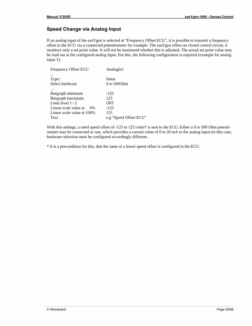
Manual 37205D easYgen-1000 - Genset Control
© Woodward Page 63/68
Speed Change via Analog Input If an analog input of the easYgen is selected at "Frequency Offset ECU", it is possible to transmit a frequency offset to the ECU via a connected potentiometer for example. The easYgen offers no closed control circuit, it monitors only a set point value. It will not be monitored whether this is adjusted. The actual set point value may be read out at the configured analog input. For this, the following configuration is required (example for analog input 1):
Frequency Offset ECU AnalogIn1 ... Type: linear Select hardware 0 to 500Ohm … Bargraph minimum -125 Bargraph maximum 125 Limit level 1 / 2 OFF Linear scale value at 0% -125 Linear scale value at 100% 125 Text e.g "Speed Offset ECU"
With this settings, a rated speed offset of -125 to 125 r/min* is sent to the ECU. Either a 0 to 500 Ohm potenti-ometer may be connected or one, which provides a current value of 0 to 20 mA to the analog input (in this case, hardware selection must be configured accordingly different. * It is a precondition for this, that the same or a lower speed offset is configured in the ECU.
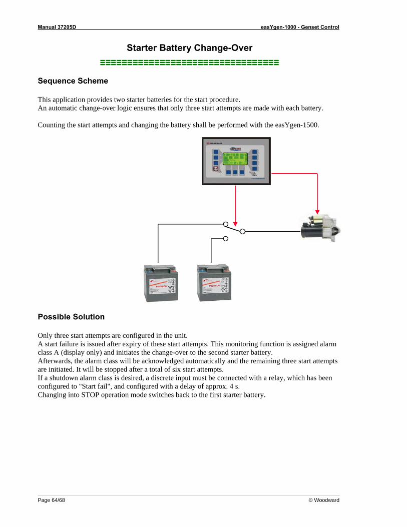
Manual 37205D easYgen-1000 - Genset Control
Page 64/68 © Woodward
Starter Battery Change-Over ≡≡≡≡≡≡≡≡≡≡≡≡≡≡≡≡≡≡≡≡≡≡≡≡≡≡≡≡≡≡≡≡≡
Sequence Scheme This application provides two starter batteries for the start procedure. An automatic change-over logic ensures that only three start attempts are made with each battery. Counting the start attempts and changing the battery shall be performed with the easYgen-1500.
Possible Solution Only three start attempts are configured in the unit. A start failure is issued after expiry of these start attempts. This monitoring function is assigned alarm class A (display only) and initiates the change-over to the second starter battery. Afterwards, the alarm class will be acknowledged automatically and the remaining three start attempts are initiated. It will be stopped after a total of six start attempts. If a shutdown alarm class is desired, a discrete input must be connected with a relay, which has been configured to "Start fail", and configured with a delay of approx. 4 s. Changing into STOP operation mode switches back to the first starter battery.
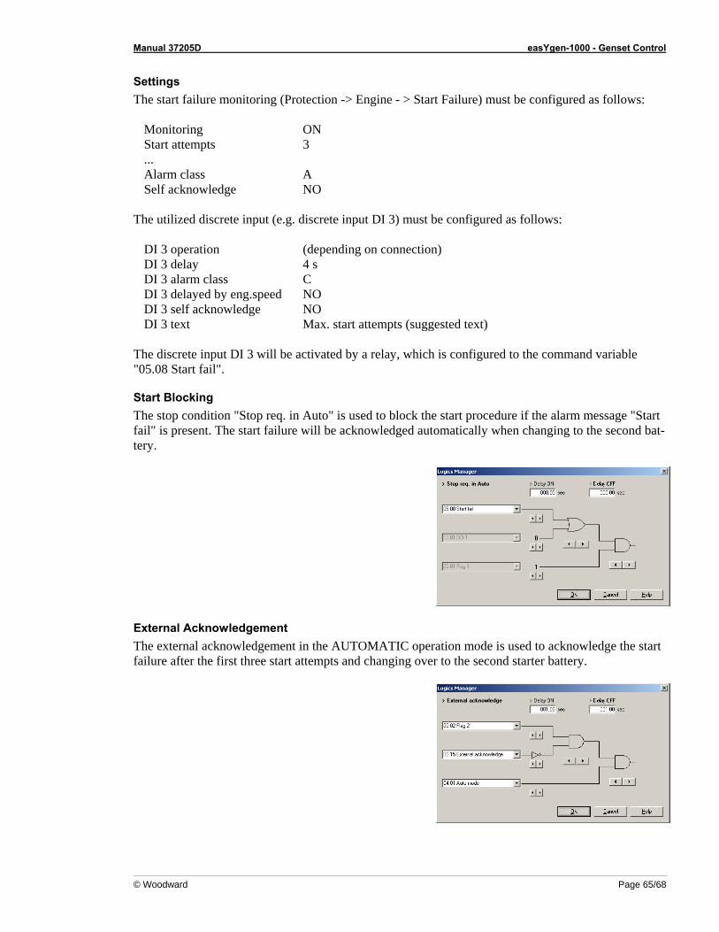
Manual 37205D easYgen-1000 - Genset Control
© Woodward Page 65/68
Settings The start failure monitoring (Protection -> Engine - > Start Failure) must be configured as follows:
Monitoring ON Start attempts 3 ... Alarm class A Self acknowledge NO
The utilized discrete input (e.g. discrete input DI 3) must be configured as follows:
DI 3 operation (depending on connection) DI 3 delay 4 s DI 3 alarm class C DI 3 delayed by eng.speed NO DI 3 self acknowledge NO DI 3 text Max. start attempts (suggested text)
The discrete input DI 3 will be activated by a relay, which is configured to the command variable "05.08 Start fail".
Start Blocking The stop condition "Stop req. in Auto" is used to block the start procedure if the alarm message "Start fail" is present. The start failure will be acknowledged automatically when changing to the second bat-tery.
External Acknowledgement The external acknowledgement in the AUTOMATIC operation mode is used to acknowledge the start failure after the first three start attempts and changing over to the second starter battery.
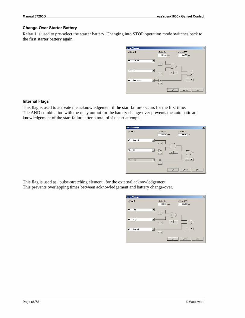
Manual 37205D easYgen-1000 - Genset Control
Page 66/68 © Woodward
Change-Over Starter Battery Relay 1 is used to pre-select the starter battery. Changing into STOP operation mode switches back to the first starter battery again.
Internal Flags This flag is used to activate the acknowledgement if the start failure occurs for the first time. The AND combination with the relay output for the battery change-over prevents the automatic ac-knowledgement of the start failure after a total of six start attempts.
This flag is used as "pulse-stretching element" for the external acknowledgement. This prevents overlapping times between acknowledgement and battery change-over.
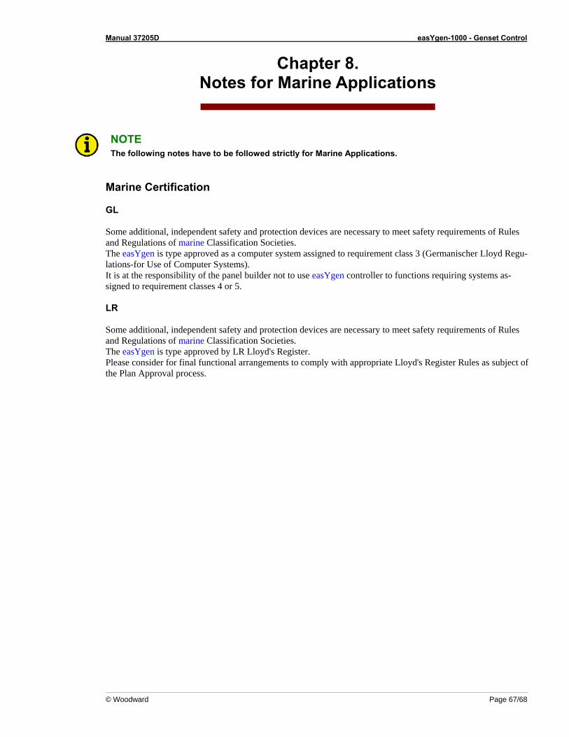
Manual 37205D easYgen-1000 - Genset Control
© Woodward Page 67/68
Chapter 8. Notes for Marine Applications
NOTE The following notes have to be followed strictly for Marine Applications.
Marine Certification GL Some additional, independent safety and protection devices are necessary to meet safety requirements of Rules and Regulations of marine Classification Societies. The easYgen is type approved as a computer system assigned to requirement class 3 (Germanischer Lloyd Regu-lations-for Use of Computer Systems). It is at the responsibility of the panel builder not to use easYgen controller to functions requiring systems as-signed to requirement classes 4 or 5. LR Some additional, independent safety and protection devices are necessary to meet safety requirements of Rules and Regulations of marine Classification Societies. The easYgen is type approved by LR Lloyd's Register. Please consider for final functional arrangements to comply with appropriate Lloyd's Register Rules as subject of the Plan Approval process.
We appreciate your comments about the content of our publications. Please send comments to: [email protected]
Please include the manual number from the front cover of this publication.
Woodward GmbH Handwerkstrasse 29 - 70565 Stuttgart - Germany
Phone +49 (0) 711-789 54-0 • Fax +49 (0) 711-789 54-100 [email protected]
Homepage
http://www.woodward.com/power
Woodward has company-owned plants, subsidiaries, and branches, as well as authorized distributors and other authorized service and sales facilities throughout the world.
Complete address/phone/fax/e-mail information
for all locations is available on our website (www.woodward.com).
2007/2/Stuttgart