Embed Size (px)
Citation preview

7/29/2019 Earthquake Resistant Design of Retaining Structures
http://slidepdf.com/reader/full/earthquake-resistant-design-of-retaining-structures 1/25
EARTHQUAKE RESISTANT DESIGNOF RETAINING STRUCTURES

7/29/2019 Earthquake Resistant Design of Retaining Structures
http://slidepdf.com/reader/full/earthquake-resistant-design-of-retaining-structures 2/25
PREAMBLE AND BACKGROUND • Design of retaining walls under seismic condition is very
important in earthquake prone areas to reduce thedevastating effect of earthquake
• Evaluation of earth pressure under seismic condition isimportant
• Estimation of passive pressure under both static and seismicconditions are very important for the design of retainingwalls, anchors, foundations etc
• Research on static passive earth pressure is plenty whereasthe same under seismic condition is still lacking
7/29/2019 Earthquake Resistant Design of Retaining Structures
http://slidepdf.com/reader/full/earthquake-resistant-design-of-retaining-structures 3/25
RETAINING STRUCTURES
• A retaining wall is a
structure designed andconstructed to resist the
lateral pressure of soil
when there is a desired
change in ground elevation
that exceeds the angle of
repose of the soil
7/29/2019 Earthquake Resistant Design of Retaining Structures
http://slidepdf.com/reader/full/earthquake-resistant-design-of-retaining-structures 4/25
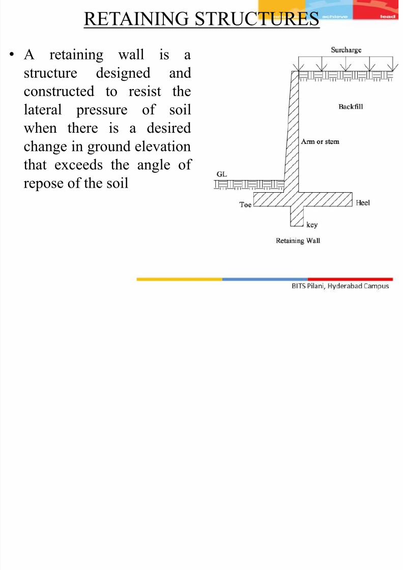
TYPES OF RETAINING WALLS Gravity Retaining Wall
• Provides stability by virtue of itsown weight
• Massive in size
•
Built in stone masonry and plainconcrete
• Thickness of the wall is governed
by the need to limit the resulting
tensile stress to its permissiblelimit
• Plain concrete gravity walls are
not used for heights exceeding
about 3 m, for economic reasons
Toe Heel
Retained
Earth
7/29/2019 Earthquake Resistant Design of Retaining Structures
http://slidepdf.com/reader/full/earthquake-resistant-design-of-retaining-structures 5/25
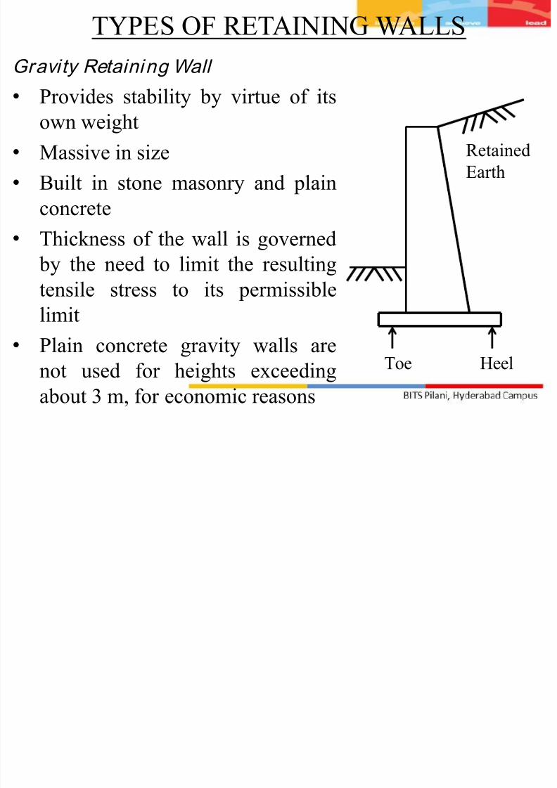
TYPES OF RETAINING WALLS Canti lever Wall
• Most common type of
retaining structure
• Economical for heights
up to about 8 m• Consists of a vertical
stem and a base slab,
made up of two distinct
regions, a heel slab and
a toe slab
Toe Heel
Retained
Earth
7/29/2019 Earthquake Resistant Design of Retaining Structures
http://slidepdf.com/reader/full/earthquake-resistant-design-of-retaining-structures 6/25
Canti lever Wall
• All three components behave as one-way cantilever slabs:
• The 'stem‘ acts as a vertical cantilever under the lateral
earth pressure
• The 'heel slab' acts as a horizontal cantilever under theaction of the weight of the retained earth
• The 'toe slab' also acts as a cantilever under the action of
the resulting soil pressure (acting upward).
• The stability of the wall is maintained essentially by the
weight of the earth on the heel slab plus the self weight
of the structure.
TYPES OF RETAINING WALLS

7/29/2019 Earthquake Resistant Design of Retaining Structures
http://slidepdf.com/reader/full/earthquake-resistant-design-of-retaining-structures 7/25
Counterfor t wall
• For large heights, in a
cantilever retaining wall,
the bending moments
developed become verylarge
• Bending moments can be
reduced by introducing
transverse supports,called counterforts
TYPES OF RETAINING WALLS Stem
Heel Slab
Counterfort
Earth retainedon this side

7/29/2019 Earthquake Resistant Design of Retaining Structures
http://slidepdf.com/reader/full/earthquake-resistant-design-of-retaining-structures 8/25
Counterfor t wall
• Counterforts interconnect the stem with the heel slab
• The counterforts are concealed within the retained earth
• Such a retaining wall structure is called the counterfort wall
• Economical for heights above 7 m
• Behave essentially as vertical cantilever beams of T-section
and varying depth
•The counterforts subdivide the vertical slab (stem) intorectangular panels
TYPES OF RETAINING WALLS
7/29/2019 Earthquake Resistant Design of Retaining Structures
http://slidepdf.com/reader/full/earthquake-resistant-design-of-retaining-structures 9/25
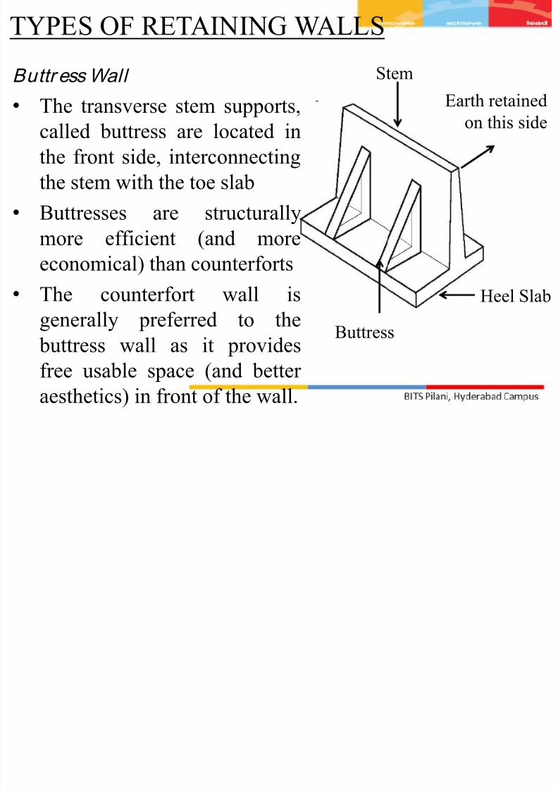
Buttr ess Wall
• The transverse stem supports,
called buttress are located in
the front side, interconnecting
the stem with the toe slab• Buttresses are structurally
more efficient (and more
economical) than counterforts
• The counterfort wall isgenerally preferred to the
buttress wall as it provides
free usable space (and better
aesthetics) in front of the wall.
TYPES OF RETAINING WALLS Stem
Heel Slab
Buttress
Earth retainedon this side

7/29/2019 Earthquake Resistant Design of Retaining Structures
http://slidepdf.com/reader/full/earthquake-resistant-design-of-retaining-structures 10/25
OTHER TYPES OF RETAINING STRUCTURE • Exterior walls in the
basement of a building
• Wall-type bridge abutments
Toe Heel
RetainedEarthFloor Slab
Wall
Toe Heel
Retained
EarthBridge Deck
Wall
Abutment
Approach
Pavement
7/29/2019 Earthquake Resistant Design of Retaining Structures
http://slidepdf.com/reader/full/earthquake-resistant-design-of-retaining-structures 11/25
LATERAL EARTH PRESSURE
Types of lateral earth pressure
• Active pressure due to earth fill
• Passive pressure due to earth fill
• Active Pressure Due to Uniform Surcharge
• Passive Pressure Due to Uniform Surcharge
7/29/2019 Earthquake Resistant Design of Retaining Structures
http://slidepdf.com/reader/full/earthquake-resistant-design-of-retaining-structures 12/25
ACTIVE PRESSURE DUE TO EARTH FILL
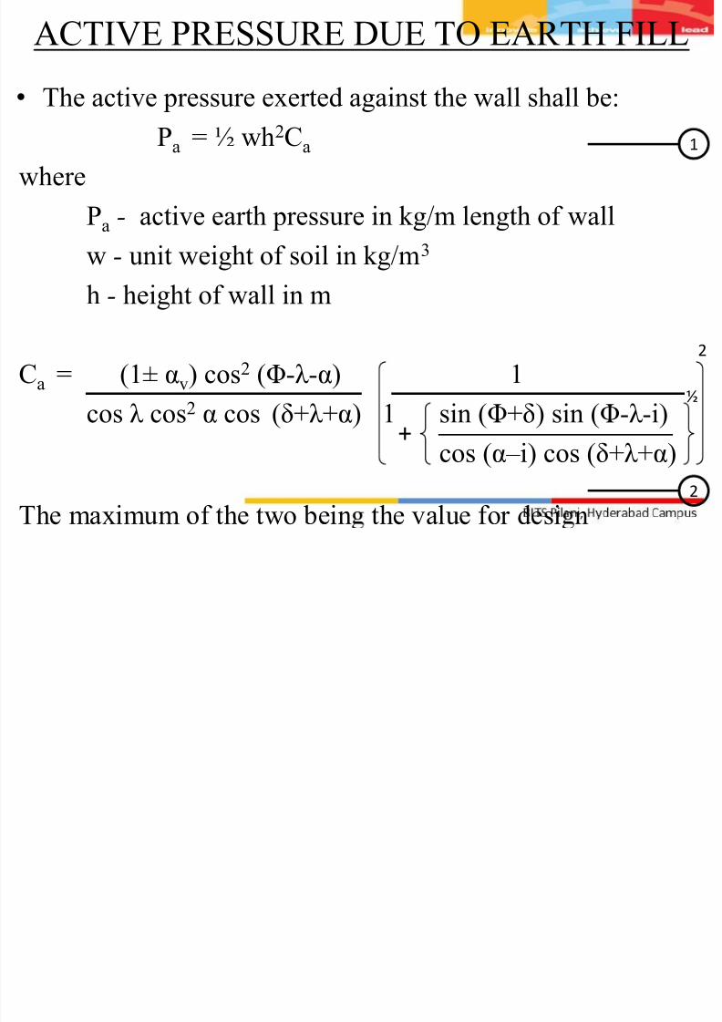
• The active pressure exerted against the wall shall be:
Pa = ½ wh2Ca
where
Pa - active earth pressure in kg/m length of wall
w - unit weight of soil in kg/m3
h - height of wall in m
Ca = (1± αv) cos2 (Φ-λ -α) 1cos λ cos2 α cos (δ+λ +α) 1 sin (Φ+δ) sin (Φ-λ -i)
cos (α– i) cos (δ+λ +α)
The maximum of the two bein the value for desi n
+
2
1
2
½

7/29/2019 Earthquake Resistant Design of Retaining Structures
http://slidepdf.com/reader/full/earthquake-resistant-design-of-retaining-structures 13/25
ACTIVE PRESSURE DUE TO EARTH FILL
where
αv - vertical seismic coefficient - its direction being
taken consistent throughout the stability
analysis of wall and equal to (½) α h
Φ - angle of internal friction of soilλ - tan-1 αh / (1± αv)
α - angle which earth face of the wall makes with the
vertical
i - slope of earth fill
δ - angle of friction between the wall and earth fill
αh - horizontal seismic coefficient
7/29/2019 Earthquake Resistant Design of Retaining Structures
http://slidepdf.com/reader/full/earthquake-resistant-design-of-retaining-structures 14/25
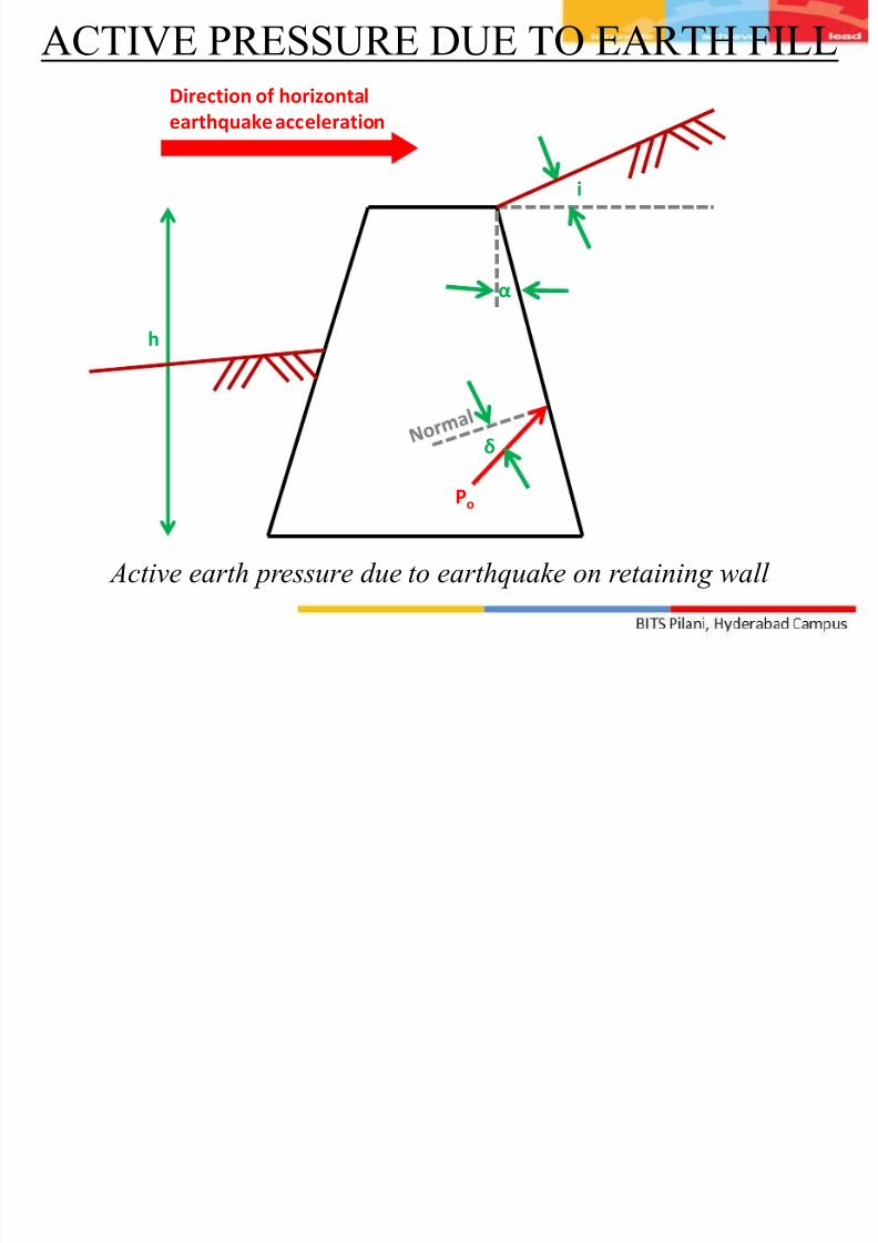
ACTIVE PRESSURE DUE TO EARTH FILL
i
h
Direction of horizontal
earthquake acceleration
Active earth pressure due to earthquake on retaining wall
δ
Po
α
7/29/2019 Earthquake Resistant Design of Retaining Structures
http://slidepdf.com/reader/full/earthquake-resistant-design-of-retaining-structures 15/25
ACTIVE PRESSURE DUE TO EARTH FILL
Point of appl ication
• From the total pressure computed subtract the static active
pressure obtained by putting αh = αv = λ = 0 in the
expression (1) and (2)
•
The remainder is the dynamic increment• The static component of the total pressure shall be applied
at an elevation h/3 above the base of the wall
• The point of application of the dynamic increment shall be
assumed to be at mid-height of the wall
7/29/2019 Earthquake Resistant Design of Retaining Structures
http://slidepdf.com/reader/full/earthquake-resistant-design-of-retaining-structures 16/25
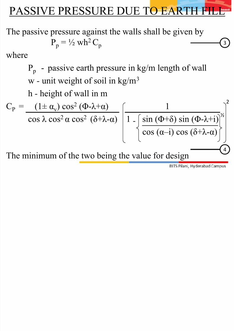
PASSIVE PRESSURE DUE TO EARTH FILL
The passive pressure against the walls shall be given by
P p = ½ wh2 C p
where
P p - passive earth pressure in kg/m length of wall
w - unit weight of soil in kg/m3 h - height of wall in m
CP = (1± αv) cos2 (Φ-λ +α) 1
cos λ cos2
α cos2
(δ+λ -α) 1 sin (Φ+δ) sin (Φ-λ +i)cos (α– i) cos (δ+λ -α)
The minimum of the two being the value for design
-
2
3
4
½
7/29/2019 Earthquake Resistant Design of Retaining Structures
http://slidepdf.com/reader/full/earthquake-resistant-design-of-retaining-structures 17/25
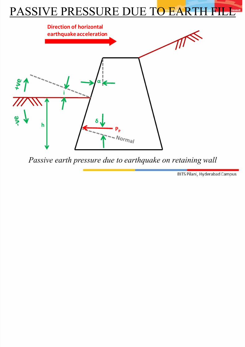
PASSIVE PRESSURE DUE TO EARTH FILL
δ
i
α
h PP
Direction of horizontal
earthquake acceleration
Passive earth pressure due to earthquake on retaining wall
7/29/2019 Earthquake Resistant Design of Retaining Structures
http://slidepdf.com/reader/full/earthquake-resistant-design-of-retaining-structures 18/25
PASSIVE PRESSURE DUE TO EARTH FILL
Point of appl ication
• From the total pressure computed subtract the total pressure
obtained by putting αh = αv = λ = 0 in the expression (1)
and (2)
•
The remainder is the dynamic decrement• The static component of the total pressure shall be applied
at an elevation h/3 above the base of the wall
• The point of application of the dynamic increment shall be
assumed to be at an elevation of 0.66h above the base of
the wall
7/29/2019 Earthquake Resistant Design of Retaining Structures
http://slidepdf.com/reader/full/earthquake-resistant-design-of-retaining-structures 19/25
Active Pressure Due to Uniform Surcharge
The active pressure against the wall due to a uniform
surcharge of intensity q per unit area of the inclined earth fillsurface shall be
(Pa)q = qh cos α Ca
cos (α – i)
Point of appl ication
•
The dynamic increment in active pressures due to uniformsurcharge shall be applied at an elevation of 0.66 h above
the base of the wall, while the static component shall be
applied at mid-height of the wall
5
7/29/2019 Earthquake Resistant Design of Retaining Structures
http://slidepdf.com/reader/full/earthquake-resistant-design-of-retaining-structures 20/25
Passive Pressure Due to Uniform Surcharge
The passive pressure against the wall due to a uniform
surcharge of intensity q per unit area of the inclined earth fillshall be
(Pa)q = qh cos α Ca
cos (α – i)
Point of appl ication
•
The dynamic decrement in passive pressures due to uniformsurcharge shall be applied at an elevation of 0.66 h above
the base of the-walls while the static component shall be
applied at mid-height of the wall.
6
7/29/2019 Earthquake Resistant Design of Retaining Structures
http://slidepdf.com/reader/full/earthquake-resistant-design-of-retaining-structures 21/25
EFFECT OF SATURATION
• For saturated earth fill, the saturated unit weight of the soil
shall be used• For submerged earth fill, the dynamic increment or
decrement in active and passive earth pressure during
earthquakes shall be found from expressions given in
equations 1,2,3 and 4 with the following modifications:
• The value of δ shall be taken as ½ the value of δ for dry
backfill
•Buoyant unit weight shall be adopted
• From the value of earth pressure found out, subtract the
value of earth pressure determined by putting
αh = αv = λ = 0 but using buoyant unit weight.
• The remainder shall be dynamic increment.

7/29/2019 Earthquake Resistant Design of Retaining Structures
http://slidepdf.com/reader/full/earthquake-resistant-design-of-retaining-structures 22/25
EFFECT OF SATURATION
• The value of λ shall be taken as follows:
λ = tan-1 ws αh
ws-1 ( 1 ± αv )
where
ws - saturated unit weight of soil in gm/cc
αh - horizontal seismic coefficient
αv - vertical seismic coefficient which is ½ αh
• Hydrodynamic pressure on account of water contained inearth fill shall not be considered separately as the effect of
acceleration on water has been considered indirectly
7/29/2019 Earthquake Resistant Design of Retaining Structures
http://slidepdf.com/reader/full/earthquake-resistant-design-of-retaining-structures 23/25
PARTIALLY SUBMERGED BACKFILL
• The ratio of the lateral dynamic increment in active
pressures to the vertical pressures at various depths alongthe height of wall may be taken
• The pressure distribution of dynamic increment in active
pressures may be obtained by multiplying the vertical
effective pressures by the coefficients in fig on next slide at
corresponding depths
• Similar procedure may be utilized for determining the
distribution of dynamic decrement in passive pressures
7/29/2019 Earthquake Resistant Design of Retaining Structures
http://slidepdf.com/reader/full/earthquake-resistant-design-of-retaining-structures 24/25
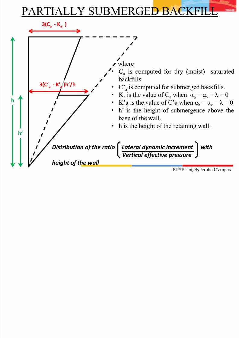
PARTIALLY SUBMERGED BACKFILL
h
h’
3(Ca - Ka )
3(C’a - K’a )h’/h
where
• Ca is computed for dry (moist) saturated
backfills
• C’a is computed for submerged backfills.
• K a is the value of Ca when αh = αv = λ = 0
• K’a is the value of C’a when αh = αv = λ = 0
• h’ is the height of submergence above the
base of the wall.
• h is the height of the retaining wall.
Distribution of the ratio Lateral dynamic increment with
Vertical effective pressure
height of the wall
7/29/2019 Earthquake Resistant Design of Retaining Structures
http://slidepdf.com/reader/full/earthquake-resistant-design-of-retaining-structures 25/25
REFERENCE
• IS 1893 : 1984
• Reinforced concrete design by S Unnikrishna Pillai &
Devdas Menon