Embed Size (px)
Citation preview

Earthquake Resistant Design ofTied-Back Retaining Structures
Kevin McManus
McManus Geotech


Summary of Procedure
Calculate apparent earth pressure, p, using M-O value Kae instead of Ka
Use traditional apparent earth pressure diagram to size wall elements
Extend anchor free lengths to beyond slip plane defined by M-O equations
Perform stability checks using Kae and Kpe from M-O equation


0
20
40
60
80
100
120
140
160
180
0 0.1 0.2 0.3 0.4
Design PGA
Wall D
isp
lac
em
en
t (m
m)
1.0
1.5
2.0
2.5
3.0
3.5
Co
st
Ind
ex
Summary for 7 m walls (one row)
0.6 g
0.4 g
0.2 g
Soldier Piles
Anchors

Anchor Performance
-300
-250
-200
-150
-100
-50
0
50
100
150
0 5 10 15 20 25
Time (s)
Wall
Cre
st
Dis
pla
cem
en
t (m
m)
0
20
40
60
80
100
120
140
160
180
An
ch
or
Fo
rce (
KN
/m)
Wall Crest Displacement
Anchor Force

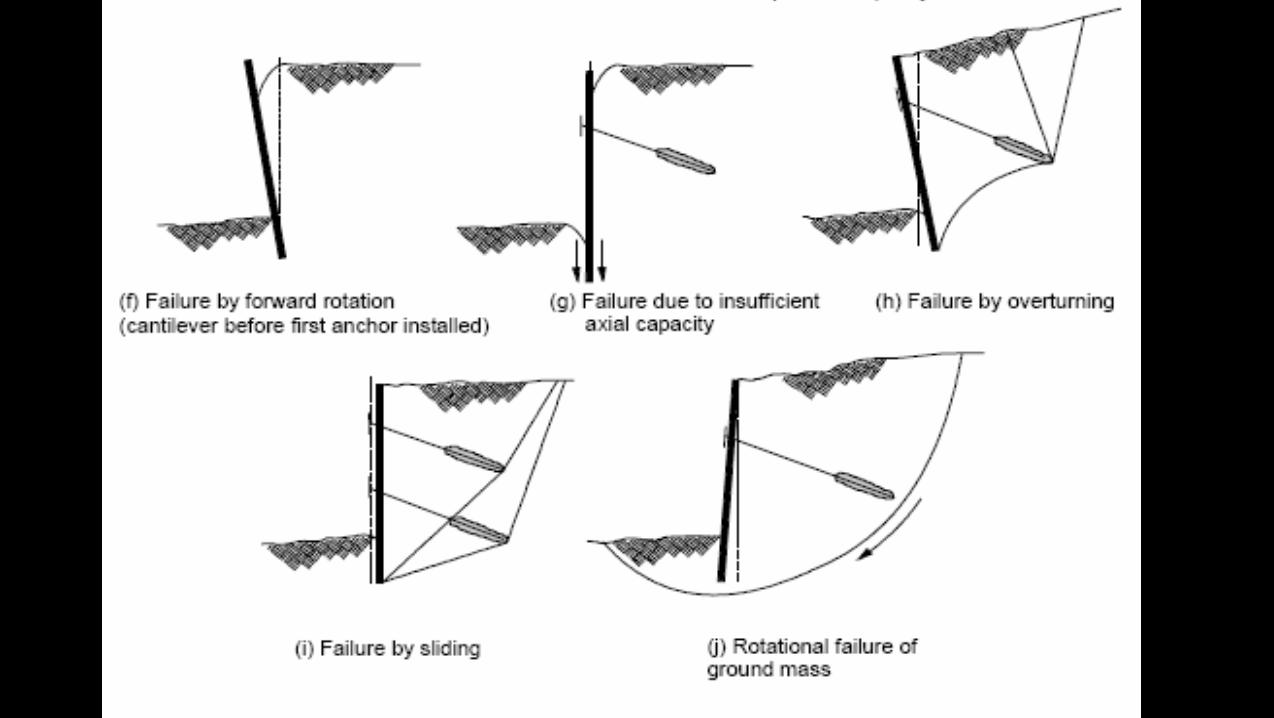
Conclusions
Design procedure based closely on existing, well proven, semi-empirical procedure
Trial designs tested using numerical, inelastic, time-history analyses with multiple EQ records up to 0.6 g
Designs found to be robust: All walls remained stable with anchor forces safely below UTS
Walls reached yield in extreme cases
Large permanent deformations in some cases

Conclusions (2)
Deformations reduced if wall designed to resist pseudo-static acceleration
Wall cost increases rapidly as design acceleration increases
Optimum probably about ½ PGA

ThankyouThis project was funded by EQC Research
Foundation under research grant 06/517
Special thanks to EQC for their continuing support for EQ engineering research in NZ
McManus Geotech