Embed Size (px)
Citation preview
Dynamic Analysis of a Double-sided ActuatedMEMS Oscillator Using Second-order Averaging
A. Bhushan, Member, IAENG, M. M. Inamdar, and D. N. Pawaskar, Member, IAENG
Abstract—MEMS oscillators have numerous applications asultra-sensitive sensors, switches, and signal-processing elements.An important class of MEMS oscillators is double-sided electro-statically actuated microbeams. This investigation is concernedwith analytical study of nonlinear resonance behaviour ofsuch oscillators using averaging method. We have modelleda microbeam oscillator using Euler-Bernoulli beam theoryand Galerkin formulation. The model takes into account theclassical nonlinearities of geometric and electrostatic originalong with the effects of both linear and nonlinear damp-ing. The formulated mathematical model is a single-degreeof freedom quintic oscillator and contains both symmetriccubic and quintic nonlinearities and asymmetric quadraticand quartic nonlinearities. Second-order averaging method, incontrast to first-order averaging method which is suitable onlyfor symmetric nonlinearities, has been employed to take intoaccount both symmetric and asymmetric nonlinear terms. Theaveraging solution is validated by comparing the results withnumerical solutions. Using our analytical solution, change inqualitative nature (hardening, mixed hardening-softening, andsoftening) of resonance curves with variation of DC voltagehas been explained. Our analytical solution is a useful tool forpracticing engineers for fast analysis of resonance curves ofMEMS oscillators.
Index Terms—MEMS, resonance curves, averaging method,double-sided oscillator, electrostatic actuation
I. INTRODUCTION
M INIATURISED devices of microelectromechanicalsystems (MEMS) are used as sensors [1], switches
[2], [3], and signal processing devices [4]. These devicesare actuated and their responses are detected using differ-ent electrostatic, magnetomotive, piezoelectric etc. methods.Electrostatic method is a principal way to operate MEMS os-cillators in which a beam is placed above a plate electrode orplaced in between two parallel plate electrodes in capacitivearrangement [5], [6]. Biased DC and AC voltages betweenmicrobeam and plate electrode(s) are applied for driving theoscillator. This paper is concerned with nonlinear dynamicsstudy of a double-sided electrostatically actuated microbeamoscillator.
Dynamic responses of MEMS oscillators are nonlinear innature primarily due to geometric nonlinearity of microbeamand electrostatic actuation nonlinearity. Younis and Alsaleem[1] have explored the importance of dynamic instability and
Manuscript received March 15, 2013. This work was supported byDepartment of Science and Technology, Government of India (Grant No. -SR/FTP/ETA-031/2009).
A. Bhushan is with the Mechanical Engineering Department ofIndian Institute of Technology Bombay, Mumbai, India (email:[email protected]).
M. M. Inamdar is with the Civil Engineering Department of Indian Insti-tute of Technology Bombay, Mumbai, India (email: [email protected]).
D. N. Pawaskar is with the Mechanical Engineering Departmentof Indian Institute of Technology Bombay, Mumbai, India (email:[email protected], phone: +91-22-2576-7548).
bifurcation of electrostatically actuated microbeam oscilla-tors in mass-sensing and switching applications. Stambaughand Chan [2] have devised noise-induced switching in non-linear electrostatically operated torsional micromechanicaloscillators. In a recent work, internal resonance between flex-ure and torsional modes of vibration has been used to achievefrequency stabilization in micromechanical oscillators [7].
Double-sided actuated microbeam oscillators have beeninvestigated both theoretically and experimentally in earlierresearch works [6], [8]. Kacem et al. [6] have studiedprimary resonance behaviour of a double-sided actuated mi-crobeam resonator using first-order averaging method. Theyhave observed hardening, softening, and mixed hardening-softening behaviour in primary resonance and the natureof resonance curves depends on the separation betweenelectrodes plates and microbeam and magnitude of appliedDC and AC voltages. Kacem and Hentz [9] have alsoexperimentally demonstrated that mixed hardening-softeningresonance behaviour can be achieved in electrostaticallyactuated micromechanical resonators. Double-sided actuatedmicrobeam oscillators have also been experimentally studiedby Shao et al. [10]. They have demonstrated that mechanicaland electrostatic nonlinearities of third order can be canceledout at critical magnitude of electrostatic actuation and itresults in improvement in critical vibration amplitude forlinear operation of the oscillators. Mestrom et al. [8] havecarried out numerical simulation of their experimental resultsof a double-sided actuated microbeam resonator. They ob-served softening behaviour in the resonance curves and theydid numerical simulation using a single-degree of freedommodel. Further Mestrom et al. [11] have also observedexperimentally both hardening and softening behaviour inresonance curves. Juillard et al. [12] have proposed a closed-loop control scheme to achieve large amplitude motionfor resonant accelerometer using double-sided actuation anddetection techniques.
Double-sided actuated MEMS beam oscillators have beeninvestigated previously, but special focus has not been givenon analytical modelling and analysis of initially deflectedmicrobeams due to asymmetric electrostatic loading due todifference in applied biased DC voltages or gaps betweenthe two electrodes and the microbeam. Asymmetric non-linearities appear in the dynamic equation of motion of amicrobeam oscillator due to such asymmetric electrostaticloading may have significant effects on resonance curves.In this work, we use a single-degree of freedom model asa forced quintic oscillator for investigation, that has beenderived using Euler-Bernoulli beam theory and Galerkinformulation. Second-order averaging method has been ap-plied to solve the problem and the results are comparedwith numerical solutions. An algebraic equation, which takesinto account the effects of both symmetric and asymmetric
Proceedings of the World Congress on Engineering 2013 Vol III, WCE 2013, July 3 - 5, 2013, London, U.K.
ISBN: 978-988-19252-9-9 ISSN: 2078-0958 (Print); ISSN: 2078-0966 (Online)
WCE 2013

Fig. 1. Double-side actuation mechanism for a microbeam oscillator
nonlinearities, has been provided from averaging analysis toobtain resonance curves.The effects of asymmetric quadraticand quartic nonlinearities on resonance curves are quantifiedand an explanation of change in hardening to softening natureof resonance curves is provided.
II. DYNAMIC MODELLING
Figure 1 depicts double-side electrostatic actuation mech-anism for a microbeam oscillator of length L, width b, andthickness h. The two electrodes 1 and 2 are placed at aseparation of g and gd from microbeam respectively. BiasedDC voltage VDC along with AC voltage of magnitude VAC
and driving frequency ωf are applied through electrode 1,whereas only DC voltage VDCd is applied through electrode2 in the electrostatic actuation. In double-side electrostaticactuation, electrode 1 is used for driving the oscillator andelectrode 2 is used for detection of dynamic responses [6],[8]. In the symbol of variables, hat (.) is used to signifydimensional form of variable to differentiate it with theirnon-dimensional form which are introduced later.
Euler-Bernoulli beam theory has been used for modellingof microbeam motion by considering the fact that MEMSbeams usually have high aspect ratios. The equation ofmotion of the microbeam oscillator is [13], [6]
EI∂4u
∂x4+ ρA
∂2u
∂t2= EA
2L
L∫0
(∂u
∂x
)2
dx+ N
∂2u∂x2
+ F (u)− Fd (u) ,(1)
where the boundary conditions are
u|x=0 = u|x= L =∂u
∂x
∣∣∣∣x=0
=∂u
∂x
∣∣∣∣x= L
= 0·
In Eq. 1, u(x, t) represents displacement of the microbeamwhose properties are density ρ, effective Young’s modulusE, cross-sectional area A, and area moment of inertia I . Theeffect of axial residual stress in microbeam is accounted byapplying uniform axial load N . Since the microbeam underconsideration has fixed-fixed boundary condition, mid-planebeam stretching occurs during oscillation. It is a source of ge-ometric nonlinearity and accounted by introducing nonlinearaxial force ∆ = (EA/2L)
∫ L
0
(u
′2)dx in Eq. 1. F (u) and
Fd(u) are nonlinear electrostatic actuation forces provided
through the electrodes 1 and 2 respectively. The expressionsfor F (u) and Fd(u) are
F (u) =ε0εr b
(VDC + VAC cos(ωf t)
)22 (g − u)
2 ζ(u, b, h, g),
Fd(u) =ε0εr bV
2DCd
2 (g + u)2 ζd(u, b, h, gd)·
Here ε0 is vacuum permittivity, whereas εr is relative per-mittivity which is taken 1 in this study. The expressions forF (u) and Fd(u) are derived by calculating force betweeninfinite parallel plate electrodes separated by distance (g− u)and (g + u) respectively. The effect of finite dimension ofthe microbeam can be accounted by including additionalfringing field factors ζ(u, b, h, gd) and ζd(u, b, h, gd) incalculating F (u) and Fd(u) respectively. Many expressionsfor accounting fringing field effects have been proposed andcan be used according to the dimension of the microbeam[14], [15].
The non-dimensionalisation of Eq. 1 has been car-ried out for simplified representation using following non-dimensional variables
u =u
g, x =
x
L, and t =
t
T·
Here T is a time constant, T =
√ρAL4/EI . The non-
dimensional form of Eq. 1 is
u′′′′
+ u =
[α1
1∫0
u′2dx+N
]u
′′
+α2V2Fe(Ga, u)− α2V
2DCdFe(Gd,−u)·
(2)
where the boundary conditions are
u|x=0 = u|x=1 = u′|x=0 = u
′|x=1 = 0·
Various coefficients of Eq. 2 are defined as
V = VDC + VAC cos(ωf t),
α1 =Ag2
2I, N =
NL2
EI, α2 =
εrε0L4
g2EI,
ωf = ωf T , Ga = 1, Gd =gdg, B0 =
b
g·
In Eq. 2, VDC , VDCd, and VAC are represented indimensional form even without hat (.). We have neglectedthe effect of fringing field in this study i.e., the values ofζ and ζd have been taken to be 1. So, the expression forfunction Fe(Gi, λ) is
Fe(Gi, λ) =B0
2 (Gi − λ)2 ·
The governing integro-partial differential equation of mo-tion (2) of the microbeam oscillator has been reduced toa single-degree of freedom (SDOF) model using Galerkinbased reduced order model technique [5]. The solution ofEq. 2 has been assumed in form
u(x, t) = φ1(x)u1(t), (3)
where φ1(x) is pre-assumed first mode shape of a straightbeam under action of applied axial load N and u1(t) isan unknown time function that serves as the generalisedtemporal co-ordinate of SDOF model. In order to reduce Eq.
Proceedings of the World Congress on Engineering 2013 Vol III, WCE 2013, July 3 - 5, 2013, London, U.K.
ISBN: 978-988-19252-9-9 ISSN: 2078-0958 (Print); ISSN: 2078-0966 (Online)
WCE 2013
2 to an SDOF equation, the assumed solution (3) has beensubstituted in the equation, φ1(x) has been multiplied to it,and finally it has been integrated from x = 0 to x = 1. Theobtained SDOF equation is
u1 + ω21u1 + k3u
31 = α2V
21∫0
Fe (Ga, φ1u1)φ1dx−
α2V2DCd
1∫0
Fe (Gd,−φ1u1)φ1dx, k3 = α1
(∫ 1
0φ
′2
1 dx)2·
(4)Here ω1 is first natural frequency of the microbeam oscillator.
The magnitude of DC voltages VDC and VDCd, and/ orseparation between electrode plates and microbeam g andgd can be different. In such asymmetric electrostatic loadingcondition, the beam is deflected towards any one electrodeplate depending upon the magnitude of DC voltages andelectrode-microbeam separations. Equation 4 can be usedto determine static deflection us0(x) = usφ1(x) by solvingthe equation after neglecting the time dependent terms. Theorigin of Eq. 4 has been shifted to us by substitutingu1(t) = us + ud(t) in Eq. 4 and derive it in terms of ud(t).The modified equation of motion becomes
ud + c1ud + c3u2dud +
m∑i=1
kiuuid =(
V 2AC cos2(ωf t) + 2VDCVAC cos(ωf t)
)(C0 +
m∑i=1
Ciuid
)(5)
andk1u = ω2
1 + 3k3u2s − V 2
DCC1 + V 2DCdC1d,
k2u = 3k3 us − V 2DCC2 + V 2
DCdC2d,k3u = k3 − V 2
DCC3 + V 2DCdC3d,
kqu = −V 2DCCq + V 2
DCdCqd; q = 4, 5...m,
Ci = 1i!α2
1∫0
F(i)e (Ga, usφ1)φi+1
1 dx; i = 0, 1, ...m,
Cid = (−1)i
i! α2
1∫0
F(i)e (Gd, −usφ1)φi+1
1 dx; i = 0, 1, ...m·
Here the function Fe of Eq. 4 has been expressed in Taylorseries of order m. In Eq. 5, damping effects on oscillationis included by adding additional terms corresponding toconventional linear viscous damping c1ud and nonlineardamping c3u
2dud. Presence of nonlinear damping has been
observed in microbeam, nanotube, and graphene resonatorsin recent experiments [16], [17]. This motivates us to includea nonlinear damping term in the mathematical model of themicrobeam oscillator.By observing the coefficients of Eqs. 4 and 5, we can identifythe contribution of geometric and electrostatic nonlinearitieson different orders of nonlinear terms. Cubic nonlinearityis present in the straight microbeam oscillator due to beamstretching (k3u
31) and is source of quadratic nonlinearity due
to deflected shape (contribution of 3k3us in k2u). HoweverVDC and VDCd contribute to all order of nonlinearities. Animportant point needs to be mentioned here - in case ofsymmetric electrostatic loading (VDC = VDCd and g = gd),asymmetric even order nonlinear terms vanish because us iszero and Ci and Cid corresponding to even order nonlinearterms are equal.
III. AVERAGING SOLUTION
A truncated form of Eq. 5 has been solved using pertur-bation method, second-order averaging [18]. The problem
under consideration for analytical treatment is
ud + c1ud + c3u2dud + k1uud + k2uu
2d + k3uu
3d+
k4uu4d + k5uu
5d = 2VDCVACC0 cos(ωf t)·
(6)
We have been investigated near primary resonance where di-rect harmonic excitation 2VDCVACC0 cos(ωf t) is the dom-inant factor. The effects of other excitation terms consistparametric excitations and V 2
AC cos2(ωf t) terms are verysmall, in compare to direct harmonic excitation, on primaryresonance curves and this will verify by comparing thenumerical solution of Eq. 5 and averaging solution of Eq.6 in Section IV. In this investigation, we limit our study tillfifth order nonlinear terms. We show in Section IV that atleast till fifth order nonlinearity is necessary to be consideredin dynamic modelling to predict the hardening, softening, andmixed hardening-softening behaviour of resonance curves ofthe investigated microbeam oscillator.
To solve the problem using averaging method, a pertur-bation problem has been formulated by introducing a smallparameter ε in Eq. 6. The perturbation problem can be statedas
ud + ω2fud = εf
(d)1 (ud, ud, ωf t) + ε2f
(d)2 (ud, ud, ωf t) ,
f(d)1 = −k21u2d − k41u4d, f
(d)2 = −µ1ud − µ3u
2dud−
k31u3d − k51u5d + p cos(ωf t)−∆1ud,
(7)and various coefficients are defined as
c1 = ε20µ1, c3 = ε20µ3, k1u = ω2n, k2u = ε0k21,
k4u = ε0k41, k3u = ε20k31, k5u = ε20k51,2VDCVACC0 = ε20p, ω
2n = ω2
f + ε20∆1·
Here ε0 is another small parameter whose significance isthat when ε = ε0, the solution of Eq. 7 is the solutionof Eq. 6. One thing important is to note here that thecoefficients of quadratic and quartic nonlinearities k2u andk4u are taken of order ε0, while other terms are taken of orderε20. It can be shown that first order averaging is capable ofproviding first approximation of symmetric nonlinear termseffects on resonance curves, whereas first order averaging ofasymmetric nonlinear terms provides only the offset distanceof oscillation from mean position as a first approximation.Therefore, we require second-order averaging solution toaccount for second approximation of asymmetric nonlinearityeffects on resonance curves. In other words, such choice ofa perturbation problem gives us first two approximations ofasymmetric nonlinearity and first approximation of symmet-ric nonlinearity effects on dynamic responses. Equation 7has been transformed in periodic standard form for makingit suitable for averaging analysis using following co-ordinatetransformation
ud = x1 cos(ωf t) + x2 sin(ωf t),ud = (−x1 sin(ωf t) + x2 cos(ωf t))ωf ·
The periodic standard form of Eq. 7 is
x1 = − ε
ωf
(f(d)1 + εf
(d)2
)sin(ωf t),
x2 =ε
ωf
(f(d)1 + εf
(d)2
)cos(ωf t)·
(8)
Proceedings of the World Congress on Engineering 2013 Vol III, WCE 2013, July 3 - 5, 2013, London, U.K.
ISBN: 978-988-19252-9-9 ISSN: 2078-0958 (Print); ISSN: 2078-0966 (Online)
WCE 2013
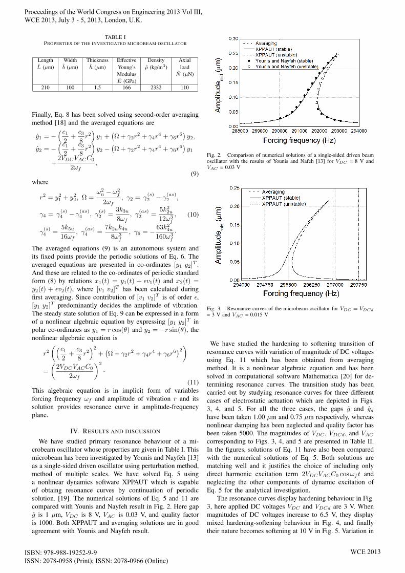
TABLE IPROPERTIES OF THE INVESTIGATED MICROBEAM OSCILLATOR
Length Width Thickness Effective Density AxialL (µm) b (µm) h (µm) Young’s ρ (kg/m3) load
Modulus N (µN)E (GPa)
210 100 1.5 166 2332 110
Finally, Eq. 8 has been solved using second-order averagingmethod [18] and the averaged equations are
y1 = −(c1
2+c38r2)y1 +
(Ω + γ2r
2 + γ4r4 + γ6r
6)y2,
y2 = −(c1
2+c38r2)y2 −
(Ω + γ2r
2 + γ4r4 + γ6r
6)y1
+2VDCVACC0
2ωf,
(9)where
r2 = y21 + y22 , Ω =ω2n − ω2
f
2ωf, γ2 = γ
(s)2 − γ
(as)2 ,
γ4 = γ(s)4 − γ
(as)4 , γ
(s)2 =
3k3u8ωf
, γ(as)2 =
5k22u12ω3
f
,
γ(s)4 =
5k5u16ωf
, γ(as)4 =
7k2uk4u8ω3
f
, γ6 = − 63k24u160ω3
f
·
(10)
The averaged equations (9) is an autonomous system andits fixed points provide the periodic solutions of Eq. 6. Theaveraged equations are presented in co-ordinates [y1 y2]T .And these are related to the co-ordinates of periodic standardform (8) by relations x1(t) = y1(t) + εv1(t) and x2(t) =y2(t) + εv2(t), where [v1 v2]T has been calculated duringfirst averaging. Since contribution of [v1 v2]T is of order ε,[y1 y2]T predominantly decides the amplitude of vibration.The steady state solution of Eq. 9 can be expressed in a formof a nonlinear algebraic equation by expressing [y1 y2]T inpolar co-ordinates as y1 = r cos(θ) and y2 = −r sin(θ), thenonlinear algebraic equation is
r2((c1
2+c38r2)2
+(Ω + γ2r
2 + γ4r4 + γ6r
6)2)
=
(2VDCVACC0
2ωf
)2
·(11)
This algebraic equation is in implicit form of variablesforcing frequency ωf and amplitude of vibration r and itssolution provides resonance curve in amplitude-frequencyplane.
IV. RESULTS AND DISCUSSION
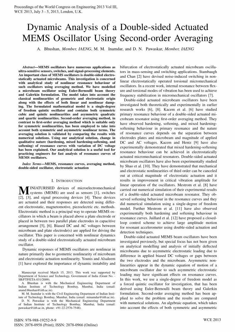
We have studied primary resonance behaviour of a mi-crobeam oscillator whose properties are given in Table I. Thismicrobeam has been investigated by Younis and Nayfeh [13]as a single-sided driven oscillator using perturbation method,method of multiple scales. We have solved Eq. 5 usinga nonlinear dynamics software XPPAUT which is capableof obtaing resonance curves by continuation of periodicsolution. [19]. The numerical solutions of Eq. 5 and 11 arecompared with Younis and Nayfeh result in Fig. 2. Here gapg is 1 µm, VDC is 8 V, VAC is 0.03 V, and quality factoris 1000. Both XPPAUT and averaging solutions are in goodagreement with Younis and Nayfeh result.
Fig. 2. Comparison of numerical solutions of a single-sided driven beamoscillator with the results of Younis and Nafeh [13] for VDC = 8 V andVAC = 0.03 V
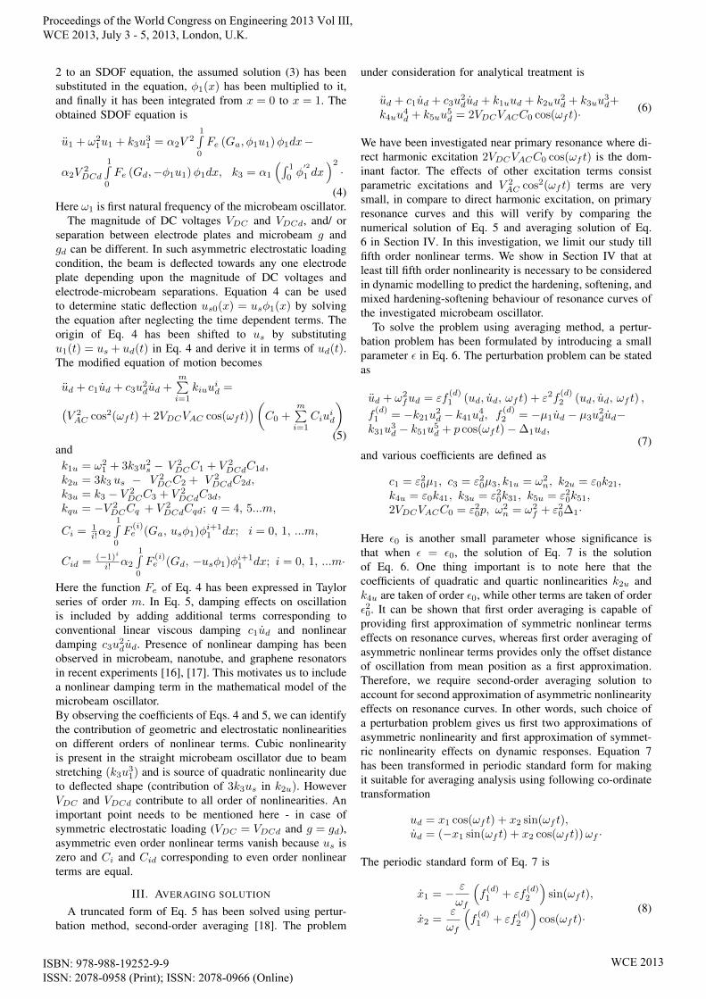
Fig. 3. Resonance curves of the microbeam oscillator for VDC = VDCd
= 3 V and VAC = 0.015 V
We have studied the hardening to softening transition ofresonance curves with variation of magnitude of DC voltagesusing Eq. 11 which has been obtained from averagingmethod. It is a nonlinear algebraic equation and has beensolved in computational software Mathematica [20] for de-termining resonance curves. The transition study has beencarried out by studying resonance curves for three differentcases of electrostatic actuation which are depicted in Figs.3, 4, and 5. For all the three cases, the gaps g and gdhave been taken 1.00 µm and 0.75 µm respectively, whereasnonlinear damping has been neglected and quality factor hasbeen taken 5000. The magnitudes of VDC , VDCd, and VAC
corresponding to Figs. 3, 4, and 5 are presented in Table II.In the figures, solutions of Eq. 11 have also been comparedwith the numerical solutions of Eq. 5. Both solutions arematching well and it justifies the choice of including onlydirect harmonic excitation term 2VDCVACC0 cosωf t andneglecting the other components of dynamic excitation ofEq. 5 for the analytical investigation.
The resonance curves display hardening behaviour in Fig.3, here applied DC voltages VDC and VDCd are 3 V. Whenmagnitudes of DC voltages increase to 6.5 V, they displaymixed hardening-softening behaviour in Fig. 4, and finallytheir nature becomes softening at 10 V in Fig. 5. Variation in
Proceedings of the World Congress on Engineering 2013 Vol III, WCE 2013, July 3 - 5, 2013, London, U.K.
ISBN: 978-988-19252-9-9 ISSN: 2078-0958 (Print); ISSN: 2078-0966 (Online)
WCE 2013
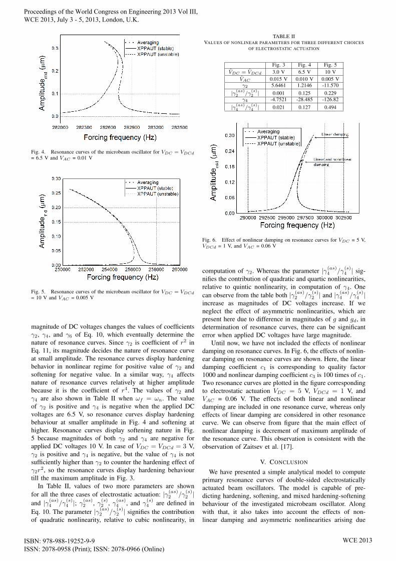
Fig. 4. Resonance curves of the microbeam oscillator for VDC = VDCd
= 6.5 V and VAC = 0.01 V
Fig. 5. Resonance curves of the microbeam oscillator for VDC = VDCd
= 10 V and VAC = 0.005 V
magnitude of DC voltages changes the values of coefficientsγ2, γ4, and γ6 of Eq. 10, which eventually determine thenature of resonance curves. Since γ2 is coefficient of r2 inEq. 11, its magnitude decides the nature of resonance curveat small amplitude. The resonance curves display hardeningbehavior in nonlinear regime for positive value of γ2 andsoftening for negative value. In a similar way, γ4 affectsnature of resonance curves relatively at higher amplitudebecause it is the coefficient of r4. The values of γ2 andγ4 are also shown in Table II when ωf = ωn. The valueof γ2 is positive and γ4 is negative when the applied DCvoltages are 6.5 V, so resonance curves display hardeningbehaviour at smaller amplitude in Fig. 4 and softening athigher. Resonance curves display softening nature in Fig.5 because magnitudes of both γ2 and γ4 are negative forapplied DC voltages 10 V. In case of VDC = VDCd = 3 V,γ2 is positive and γ4 is negative, but the value of γ4 is notsufficiently higher than γ2 to counter the hardening effect ofγ2r
2, so the resonance curves display hardening behaviourtill the maximum amplitude in Fig. 3.
In Table II, values of two more parameters are shownfor all the three cases of electrostatic actuation: |γ(as)2 /γ
(s)2 |
and |γ(as)4 /γ(s)4 |; γ
(as)2 , γ(s)2 , γ(as)4 , and γ
(s)4 are defined in
Eq. 10. The parameter |γ(as)2 /γ(s)2 | signifies the contribution
of quadratic nonlinearity, relative to cubic nonlinearity, in
TABLE IIVALUES OF NONLINEAR PARAMETERS FOR THREE DIFFERENT CHOICES
OF ELECTROSTATIC ACTUATION
Fig. 3 Fig. 4 Fig. 5VDC = VDCd 3.0 V 6.5 V 10 V
VAC 0.015 V 0.010 V 0.005 Vγ2 5.6461 1.2146 -11.570
|γ(as)2 /γ(s)2 | 0.001 0.125 0.229
γ4 -4.7521 -28.485 -126.82|γ(as)4 /γ
(s)4 | 0.021 0.127 0.494
Fig. 6. Effect of nonlinear damping on resonance curves for VDC = 5 V,VDCd = 1 V, and VAC = 0.06 V
computation of γ2. Whereas the parameter |γ(as)4 /γ(s)4 | sig-
nifies the contribution of quadratic and quartic nonlinearities,relative to quintic nonlinearity, in computation of γ4. Onecan observe from the table both |γ(as)2 /γ
(s)2 | and |γ(as)4 /γ
(s)4 |
increase as magnitudes of DC voltages increase. If weneglect the effect of asymmetric nonlinearities, which arepresent here due to difference in magnitudes of g and gd, indetermination of resonance curves, there can be significanterror when applied DC voltages have large magnitude.
Until now, we have not included the effects of nonlineardamping on resonance curves. In Fig. 6, the effects of nonlin-ear damping on resonance curves are shown. Here, the lineardamping coefficient c1 is corresponding to quality factor1000 and nonlinear damping coefficient c3 is 100 times of c1.Two resonance curves are plotted in the figure correspondingto electrostatic actuation VDC = 5 V, VDCd = 1 V, andVAC = 0.06 V. The effects of both linear and nonlineardamping are included in one resonance curve, whereas onlyeffects of linear damping are considered in other resonancecurve. We can observe from figure that the main effect ofnonlinear damping is decrement of maximum amplitude ofthe resonance curve. This observation is consistent with theobservation of Zaitsev et al. [17].
V. CONCLUSION
We have presented a simple analytical model to computeprimary resonance curves of double-sided electrostaticallyactuated beam oscillators. The model is capable of pre-dicting hardening, softening, and mixed hardening-softeningbehaviour of the investigated microbeam oscillator. Alongwith that, it also takes into account the effects of non-linear damping and asymmetric nonlinearities arising due
Proceedings of the World Congress on Engineering 2013 Vol III, WCE 2013, July 3 - 5, 2013, London, U.K.
ISBN: 978-988-19252-9-9 ISSN: 2078-0958 (Print); ISSN: 2078-0966 (Online)
WCE 2013

to asymmetric electrostatic loading on resonance curves.The analytical model is a nonlinear algebraic equation andit can be used for fast computation of resonance curvesduring design phase of double-sided actuated microbeamoscillators.
REFERENCES
[1] M. I. Younis and F. Alsaleem, “Exploration of new concepts for massdetection in electrostatically-actuated structures based on nonlinearphenomena,” Journal of Computational and Nonlinear Dynamics,vol. 4, no. 021010, 2009.
[2] C. Stambaugh and H. B. Chan, “Noise-activated switching in a drivennonlinear micromechanical oscillator,” Physical Review B, vol. 73, no.172302, 2006.
[3] M. M. Joglekar and D. N. Pawaskar, “Estimation of oscillationperiod/switching time for electrostatically actuated microbeam typeswitches,” International Journal of Mechanical Sciences, vol. 53, pp.116–125, 2011.
[4] J. F. Rhoads, S. W. Shaw, K. L. Turner, and R. Baskaran, “Tunable mi-croelectromechanical filters that exploit parametric resonance,” Journalof Vibration and Acoustics - Transactions of the ASME, vol. 127, pp.423–430, 2005.
[5] A. Bhushan, M. M. Inamdar, and D. N. Pawaskar, “Investigation ofthe internal stress effects on static and dynamic characteristics of anelectrostatically actuated beam for MEMS and NEMS application,”Microsystem Technologies, vol. 17, pp. 1779–1789, 2011.
[6] N. Kacem, S. Hentz, D. Pinto, B. Reig, and V. Nguyen, “Nonlineardynamics of nanomechanical beam resonators: improving the perfor-mance of NEMS-based sensors,” Nanotechnology, vol. 20, no. 275501,2009.
[7] D. Antonio, D. H. Zanette, and D. Lopez, “Frequency stabilization innonlinear micromechanical oscillators,” Nature Communication, vol. 3,no. 806, 2012.
[8] R. M. C. Mestrom, R. H. B. Fey, J. T. M. Beek, K. L. Phan,and H. Nijmeijer, “Modelling the dynamics of a MEMS resonator:Simulations and experiments,” Sensors and Actuators A: Physical, vol.142, pp. 306–315, 2008.
[9] N. Kacem and S. Hentz, “Bifurcation topology tuning of a mixedbehavior in nonlinear micromechanical resonators,” Applied PhysicsLetters, vol. 95, no. 183104, 2009.
[10] L. C. Shao, M. Palaniapan, and W. W. Tan, “The nonlinearitycancellation phenomenon in micromechanical resonators,” Journal ofMicromechanics and Microengineering, vol. 18, no. 065014, 2008.
[11] R. M. C. Mestrom, R. H. B. Fey, K. L. Phan, and H. Nijmeijer,“Simulations and experiments of hardening and softening resonancesin a clamped-clamped beam MEMS resonator,” Sensors and ActuatorsA: Physical, vol. 162, pp. 225–234, 2010.
[12] J. Juillard, A. Bonnoit, E. Avignon, S. Hentz, and E. Colinet, “Largeamplitude dynamics of micro/nanomechanical resonators actuated withelectrostatic pulses,” Journal of Applied Physics, vol. 107, no. 014907,2010.
[13] M. I. Younis and A. H. Nayfeh, “A study of the nonlinear response ofa resonant microbeam to an electric actuation,” Nonlinear Dynamics,vol. 31, pp. 91–117, 2003.
[14] V. Leus and D. Elata, “Fringing field effect in electrostatic actuator,”TECHNION Israel Institute of Technology, Tech. Rep., 2004.
[15] R. C. Batra, M. Porfiri, and D. Spinello, “Electromechanical model ofelectrically actuated narrow microbeams,” Journal of Microelectrome-chanical Systems, vol. 15, pp. 1175–1189, 2006.
[16] A. Eichler, J. Moser, J. Chaste, M. Zdrojek, I. Wilson-Rae, andA. Bachtold, “Nonlinear damping in mechanical resonators made fromcarbon nanotubes and graphene,” Nature Nanotechnology, vol. 6, pp.339–342, 2011.
[17] S. Zaitsev, O. Shtempluck, E. Buks, and O. Gottlieb, “Nonlinear damp-ing in a micromechanical oscillator,” Nonlinear Dynamics, vol. 67, pp.859–883, 2012.
[18] J. A. Murdock, Perturbations: Theory and Methods. New York: JohnWiley & Sons, Inc., 1991.
[19] B. Ermentrout, Simulating, analyzing, and animating dynamical sys-tems - A guide to XPPAUT for researchers and students. Philadelphia:Society for Industrial and Applied Mathematics, 2002.
[20] Wolfram Research, Inc., Mathematica Edition: Version 7.0, Cham-paign, Illinois, 2008.
Proceedings of the World Congress on Engineering 2013 Vol III, WCE 2013, July 3 - 5, 2013, London, U.K.
ISBN: 978-988-19252-9-9 ISSN: 2078-0958 (Print); ISSN: 2078-0966 (Online)
WCE 2013