Embed Size (px)
Citation preview

7/30/2019 DVR2000E Training--SECT #8 (Troubleshooting)
http://slidepdf.com/reader/full/dvr2000e-training-sect-8-troubleshooting 1/18
DVR®
2000E / DVR®
2000EC
Troubleshooting
7/30/2019 DVR2000E Training--SECT #8 (Troubleshooting)
http://slidepdf.com/reader/full/dvr2000e-training-sect-8-troubleshooting 2/18
2
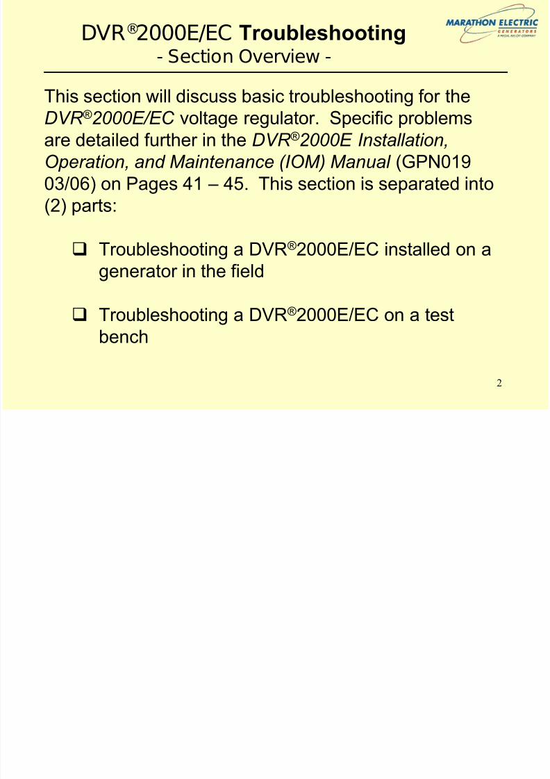
DVR®2000E/EC Troubleshooting- Section Overview -
This section will discuss basic troubleshooting for theDVR ® 2000E/EC voltage regulator. Specific problems
are detailed further in the DVR ® 2000E Installation,
Operation, and Maintenance (IOM) Manual (GPN019
03/06) on Pages 41 – 45. This section is separated into(2) parts:
Troubleshooting a DVR®2000E/EC installed on a
generator in the field
Troubleshooting a DVR®2000E/EC on a test
bench

7/30/2019 DVR2000E Training--SECT #8 (Troubleshooting)
http://slidepdf.com/reader/full/dvr2000e-training-sect-8-troubleshooting 3/18
3
DVR2000 ® E/EC Troubleshooting- Field Testing -
Troubleshooting scenarios are provided in theDVR ® 2000E Installation, Operation, and Maintenance
(IOM) Manual (GPN019 03/06) beginning on page 41.
This presentation will focus on basic troubleshooting
methods for the DVR ® 2000E/EC . Specificscenarios/problems can be discussed as a group as
required.
NOTE: Marathon Electric recommends that testing
discussed in this presentation be completed with NO-
LOAD on the generator .

7/30/2019 DVR2000E Training--SECT #8 (Troubleshooting)
http://slidepdf.com/reader/full/dvr2000e-training-sect-8-troubleshooting 4/18
4
DVR2000 ® E/EC Troubleshooting- Field Testing Note-
NOTE: It is recommended by Marathon Electric that, when possible, youutilize the „Metering‟ screen in the Marathon-DVR ® 2000E-COMS Software
for troubleshooting as this screen will provide you much insight into the the
generator system including exciter field conditions and alarm status. See
diagram below.
GeneratorOutput Voltage
GeneratorOutput Current (if CT connected)
GeneratorFrequency
(Calculated, not
measured)
Additional SystemInformation
Exciter Field
Voltage and Current
7/30/2019 DVR2000E Training--SECT #8 (Troubleshooting)
http://slidepdf.com/reader/full/dvr2000e-training-sect-8-troubleshooting 5/18
5
DVR®2000E/EC Troubleshooting- Field Testing Note-
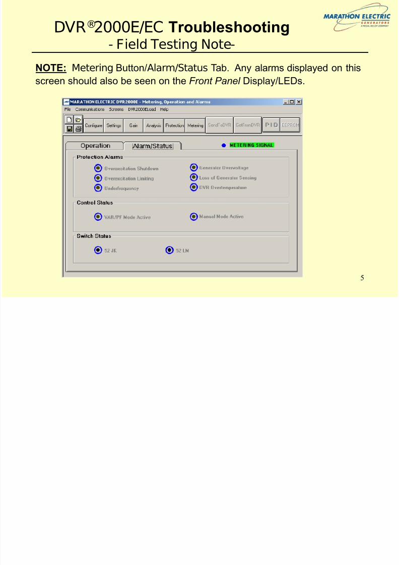
NOTE: Metering Button/Alarm/Status Tab. Any alarms displayed on thisscreen should also be seen on the Front Panel Display/LEDs.

7/30/2019 DVR2000E Training--SECT #8 (Troubleshooting)
http://slidepdf.com/reader/full/dvr2000e-training-sect-8-troubleshooting 6/18
6
DVR®2000E/EC Troubleshooting- Field Testing Basics-
In the event of a problem in which the DVR ®
2000E/EC issuspect, confirm the following (10) items with NO-LOAD on the generator:
1. Check Front Panel/Metering Screen for Alarm Status. If analarm is indicated, correct problem. These alarms are defined inthe DVR ® 2000E Installation, Operation, and Maintenance (IOM)Manual (GPN019 03/06) on Pages 23 – 24.
NOTE: If DVR ®
2000E/EC latches-off , upon applying power to theDVR ® 2000E/EC the function indicator LED on the front panel willflash rapidly for 5 seconds to indicate Latch-Off Mode prior toactivating regulation. This is very useful in troubleshooting whythe regulator is shutting down.

7/30/2019 DVR2000E Training--SECT #8 (Troubleshooting)
http://slidepdf.com/reader/full/dvr2000e-training-sect-8-troubleshooting 7/18
7
DVR®2000E/EC Troubleshooting- Field Testing Basics (Cont’d) -
2. Check the Integrity of All Connectors and Signal WireIntegrity. Correct as necessary.
3. Check Wiring Connections. The connection should be madeas shown in the IOM on Pages 33 – 36. Correct as necessary.
4. Confirm Shaft Speed. It is always recommend to verify shaftspeed with a tachometer or other equipment (i.e., not by thesound of the engine). Correct as necessary.
5. Check DVR®2000E/EC Input Power (Terminals 3 & 4). Thissupplied by the PMG and should be nominally:
a) 220 Vac, 300 Hz at 1800 RPM (60 Hz)b) 190 Vac, 250 Hz at 1500 RPM (50 Hz)
6. Check DVR®2000E/EC On-Board Fuse. If failed replace withequivalent fuse.
7/30/2019 DVR2000E Training--SECT #8 (Troubleshooting)
http://slidepdf.com/reader/full/dvr2000e-training-sect-8-troubleshooting 8/18
8
DVR®2000E/EC Troubleshooting- Field Testing Basics (Cont’d) -
7. Review DVR®
2000E/EC Settings. Confirm that the settingsare correct either using the Front Panel or Marathon-DVR ® 2000E-COMS Software.
8. Check Sensing Inputs (Terminal E1, E2, E3). Confirm thatyou are sensing the correct voltage and confirm that you are
sensing on the proper generator terminals.
9. Constant Excitation (12V Battery) Test. This test is used toisolate the DVR ® 2000E/EC and confirm that the regulator is thebasis of the problem. Disconnect all DVR ® 2000E/EC leads,isolating Leads 3, 4, E1, E2, and E3 which will have voltage on
them. Follow instructions in your generator manual for performing this test. Compare generator output voltage todatasheet (available from the Marathon Electric website or your Regional Marathon Electric Representative) for your modelgenerator.
7/30/2019 DVR2000E Training--SECT #8 (Troubleshooting)
http://slidepdf.com/reader/full/dvr2000e-training-sect-8-troubleshooting 9/18
9
DVR®2000E/EC Troubleshooting- Field Testing Basics (Cont’d) -
10a. Correct generator problem and repeat Steps #1 - #9. If there is a problem found with your generator, correct thegenerator problem and repeat these steps if your problempersists.
10b. Review IOM Pages 41 – 45. If there is no problem foundwith the generator, review the IOM for specific problem. If
a problem not listed in the IOM is found, contact your Marathon Electric Regional Representative for assistance.
NOTE: If you find the problem is related to the DVR ® 2000E/EC
regulator, it is recommended that you perform a bench test on theregulator prior to contacting your Marathon Electric Regional
Representative for a return authorization (AKA, RGA number).

7/30/2019 DVR2000E Training--SECT #8 (Troubleshooting)
http://slidepdf.com/reader/full/dvr2000e-training-sect-8-troubleshooting 10/18
10
DVR®2000E/EC Troubleshooting- Bench Testing Basics -
In the event that you replace a DVR ® 2000E/EC , it isrecommended that you do the following tests prior to
scrapping the unit or contacting your Marathon Electric
Regional Representative for return authorization (if
within warranty):
1. Confirm Internal Connections
2. Perform “Light Bulb” Test
3. Test on Known Working Generator (if possible)
7/30/2019 DVR2000E Training--SECT #8 (Troubleshooting)
http://slidepdf.com/reader/full/dvr2000e-training-sect-8-troubleshooting 11/18
11
DVR®2000E/EC Troubleshooting- Internal Connection Test -
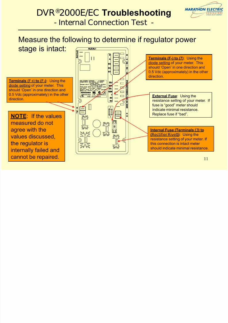
Measure the following to determine if regulator power stage is intact:
Terminals (F+) to (F-): Using thediode setting of your meter. This
should „Open‟ in one direction and
0.5 Vdc (approximately) in the other
direction.
Terminals (F-) to (7): Using the
diode setting of your meter. This
should „Open‟ in one direction and
0.5 Vdc (approximately) in the other
direction.
Internal Fuse (Terminals (3) to
(Rectifier Rivet)): Using the
resistance setting of your meter. If
this connection is intact meter
should indicate minimal resistance.
NOTE: If the values
measured do not
agree with the
values discussed,
the regulator is
internally failed and
cannot be repaired.
External Fuse: Using the
resistance setting of your meter. If
fuse is “good” meter should
indicate minimal resistance.
Replace fuse if “bad”.

7/30/2019 DVR2000E Training--SECT #8 (Troubleshooting)
http://slidepdf.com/reader/full/dvr2000e-training-sect-8-troubleshooting 12/18
12
DVR®2000E/EC Troubleshooting
- “Light Bulb” Test (Power Supply) -
• A separate power supply may be purchasedwhich will limit the current into the regulator.The power should be equivalent to:
– Volgen SPN-50-48S – See Volgen Power Supply Specifications.pdf
included on seminar compact disk for further details
• Attach the wire terminals to Terminals 3 and 4of DVR ® 2000E/EC regulator. Be sure to attach
a grounding wire prior to applying power.
NOTE 1: For the “Light Bulb” Test, Marathon Electric recommends that you use
a 48 Vdc, equivalent to the Volgen SPN-50-48S, in order to limit the amount of
current into the DVR ® 2000E/EC which could further damage the unit.
NOTE: No matter what power source you choose, be sure
that the DVR ® 2000E/EC is hard-wired to earth ground with no
smaller than 12 AWG copper wire attached to the ground
terminal on the rear of the unit case.
7/30/2019 DVR2000E Training--SECT #8 (Troubleshooting)
http://slidepdf.com/reader/full/dvr2000e-training-sect-8-troubleshooting 13/18
13
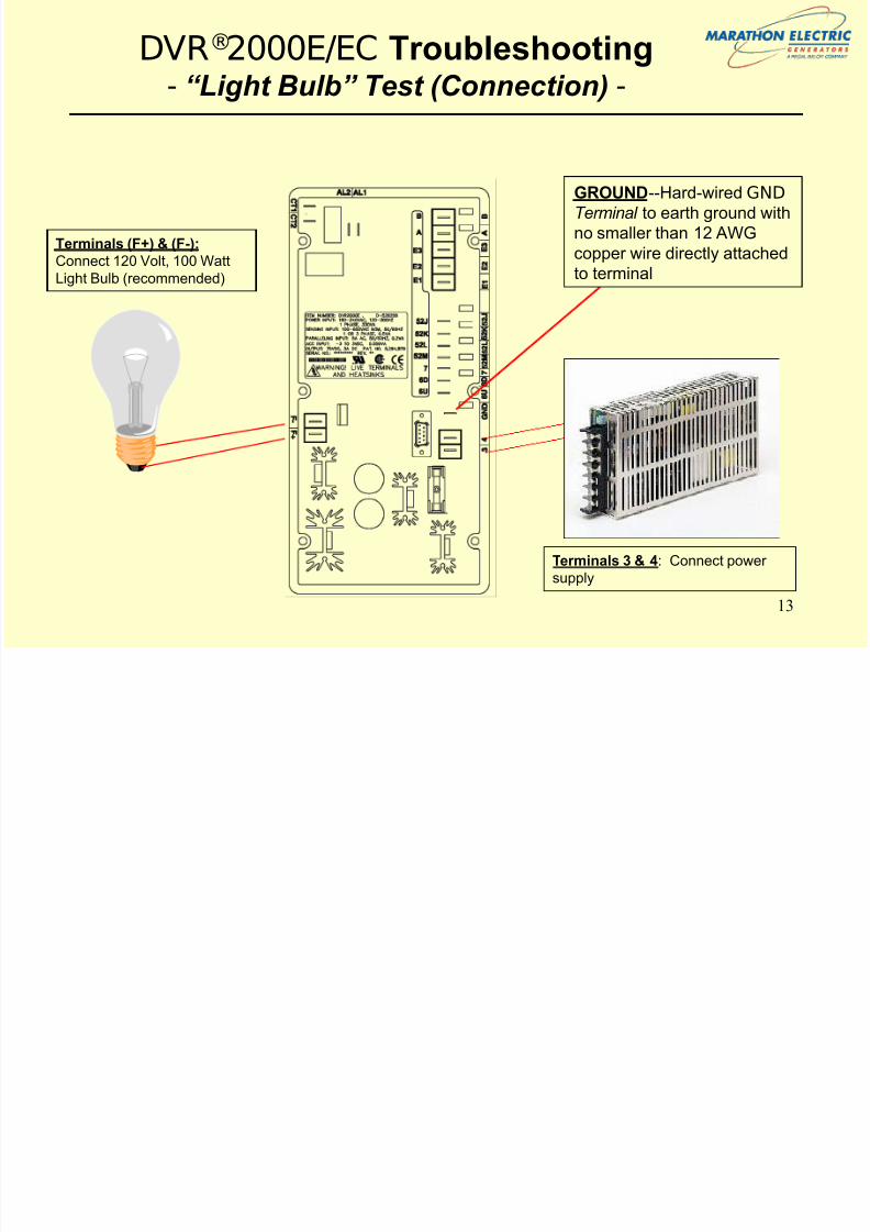
DVR®2000E/EC Troubleshooting- “Light Bulb” Test (Connection) -
Terminals 3 & 4: Connect power
supply
Terminals (F+) & (F-):
Connect 120 Volt, 100 Watt
Light Bulb (recommended)
GROUND--Hard-wired GND
Terminal to earth ground with
no smaller than 12 AWG
copper wire directly attached
to terminal

7/30/2019 DVR2000E Training--SECT #8 (Troubleshooting)
http://slidepdf.com/reader/full/dvr2000e-training-sect-8-troubleshooting 14/18
14
DVR®2000E/EC Troubleshooting- “Light Bulb” Test (Safety) -
NOTE: It is highly recommended that the protective cover be installed on the DVR ® 2000E /
DVR ® 2000EC whenever power is applied to the DVR ® 2000E / DVR ® 2000EC as the heat sinks
on the rear-side of the DVR ® 2000E / DVR ® 2000EC are live when power is applied.
Ref: IOM, Page 27
Attached protective cover BEFORE applying power.
7/30/2019 DVR2000E Training--SECT #8 (Troubleshooting)
http://slidepdf.com/reader/full/dvr2000e-training-sect-8-troubleshooting 15/18
15
DVR®2000E/EC Troubleshooting- “Light Bulb” Test (Procedure) -
1. Connect as shown.2. Apply power to DVR ® 2000E/EC and activate FCR/Manual
Mode either through the Front Panel or the Marathon-
DVR ® 2000E-COMS Software. LED #3 on the Front Panel
should be blinking in either case.
3. Using the Front Panel (LED #4) or the Marathon-DVR ® 2000E-
COMS Software (Settings Button / Set point Tab), adjust the
FCR Set point (A) up and down.
a) If you see the light bulb illumination vary, your
DVR ® 2000E/EC is outputting current and may still be intact
(confirm with generator test…see next slide)
b) If you do not see a change in the illumination of the light
bulb the DVR ® 2000E/EC may be damaged and should not
be used on another generator until fully evaluated by
qualified personnel
7/30/2019 DVR2000E Training--SECT #8 (Troubleshooting)
http://slidepdf.com/reader/full/dvr2000e-training-sect-8-troubleshooting 16/18

7/30/2019 DVR2000E Training--SECT #8 (Troubleshooting)
http://slidepdf.com/reader/full/dvr2000e-training-sect-8-troubleshooting 17/18
17
DVR®2000E/EC Troubleshooting- Summary -
In summary, prior to contacting your Marathon Electric Regional Representative to return a DVR ® 2000E/EC
voltage regulator , follow this troubleshooting sequence:
1. Confirm Internal Connections
2. Perform “Light Bulb” Test
3. Test on Known Working Generator (if possible)
7/30/2019 DVR2000E Training--SECT #8 (Troubleshooting)
http://slidepdf.com/reader/full/dvr2000e-training-sect-8-troubleshooting 18/18
DVR®2000E/EC Troubleshooting- End of Section -
QUESTIONS?