Embed Size (px)
Citation preview
International Journal of Computer Applications (0975 – 8887)
Volume 107 – No 9, December 2014
22
DSP-based Synchronization Algorithm Implementation
for OFDM
Mahmood A.K. Abdulsattar Department of Electrical Engineering University of Baghdad, Baghdad, Iraq
Raed Sattar Jebur Department of Electrical Engineering University of Baghdad, Baghdad, Iraq
ABSTRACT
Synchronization has been one of the most important research
topics in Orthogonal Frequency Division Multiplexing
(OFDM) system because of its great sensitivity towards timing and frequency offset errors. This paper describes a
real-time implementation of a timing and frequency
synchronization for OFDM system using MATLAB software
Simulink, DSP processor TMS320C6713 and Code Composer
Studio (CCS). The hardware interface converts the baseband
signal from the PC to the DSP Processor. Basic transmission
and reception performances are evaluated in real time using
Real Time data Transfer (RTDX). The practical results and
performance evaluation of the synchronization algorithms in
OFDM system is presented and discussed. The results are
plotted for different offsets of CFO and STO with different
values of signal to noise ratio. Also the bit error rate (BER)
and the mean square error (MSE) of the system is analyzed.
Keywords OFDM, Synchronization, MATLAB, Simulink, DSP.
1. INTRODUCTION In [1], the rapidly growing of telecommunication market in
the last decades create a need for new techniques that can
provide high data rates. Many digital communications services
have been deployed with constantly growing data rates like
digital radio, digital television, and mobile Internet. The
Orthogonal Frequency Division Multiplexing (OFDM)
technology is able to provide a high transmission data rate
with enhanced communication performance at a relatively
small bandwidth cost, together with proper estimation and
compensation of channel effects. Therefore, it has been widely
applied in many wireless and mobile networks. Although the
principles of OFDM modulation have been in existence since
1960, in the last years OFDM modulation is appeared as a key
modulation technique of commercial high speed
communication systems. The principal reason of this
increasing interest is due to its capability to provide high-
speed data rate transmissions with low complexity and to
counteract the Inter Symbol Interference (ISI) introduced by
dispersive channels.
On the other hand, the use of OFDM systems with a high
number of subcarriers has some drawbacks. One of the major
drawbacks of OFDM is that it is more sensitive to
synchronization errors. The performance of OFDM systems is
particularly dependent on the synchronization error which
occurs due to the Carrier Frequency Offset (CFO) and the
Symbol Timing Offset (STO). The frequency mismatch
between transmitter and receiver causes loss of orthogonally
among the subcarriers giving rise to Inter Carrier Interference
(ICI) which results in Signal to Noise Ratio (SNR) loss of the
useful signal. Incorrect symbol timing brings signals from
adjacent frames into the target frame resulting in severe ISI.
Therefore, synchronization is very important to OFDM
systems [2], [3].
In this paper, we study the DSP implementation of
synchronization algorithm for OFDM system by using
MATLAB/SIMULINK to design the model and then use the
Embedded Target for TI C6000 DSP and Real-Time
Workshop, to generate ANSI C code targeted to the Texas
Instruments DSP development boards.
2. OFDM SYNCHRONIZATION Synchronization has been one of the fundamental research
topics in OFDM system because of its sensitivity to the timing
and frequency errors [4]. In fact, STO and CFO can
significantly weaken the performance of OFDM systems.
Specifically, incorrect timing synchronization can cause
interference between successive symbols and, if not perfectly
compensated before the equalization process, can lead to
severe performance degradation. In addition, a CFO induces
an amplitude reduction of the useful signal and provokes
interference between adjacent subcarriers [5].
2.1 Timing Offset Error In an OFDM system, the IFFT and FFT are the fundamental
functions used for the modulation and demodulation of
OFDM symbol at transmitter and receiver respectively. In
order to demodulate an OFDM symbol correctly at the
receiver using N-point FFT, it is very much required to take
exact samples of transmitted OFDM symbol. The correct
starting point of FFT window is required to preserve the
orthogonality among the sub-carriers. There is lot of
advantages of OFDM system over single carrier system
however all these advantages can be useful only when the
orthogonality among sub-carriers is maintained. If one FFT
window takes sample of two different OFDM symbol then it
will generate ICI and ISI as shown in next section. Hence it
can be stated that the FFT window timing synchronization in
OFDM system is corresponds to symbol timing
synchronization in single carrier transmission system [6].
Depending on the location of the estimated starting point of
OFDM symbol, the effect of STO might be different. Figure 1
shows four different cases of timing offset, in which the
estimated starting point is exact, a little earlier, too early, or a
little later than the exact timing instance. Here, we assume that
the multi-path delay spread incurs the lagged channel response
of . In the current analysis, the effects of the noise and
channel are ignored. Referring to Figure 1, let us discuss the
effects of STO for these four different cases below.
Figure 1: Four different cases of STO [6].
International Journal of Computer Applications (0975 – 8887)
Volume 107 – No 9, December 2014
23
Case-I: This is the case when the estimated starting point of
OFDM symbol coincides with the exact timing, preserving the
orthogonality among sub-carriers, therefore the OFDM
symbol can be perfectly recovered without any type of
interference.
Case-II: This is the case when the estimated starting point of
OFDM symbol is before the exact point, yet after the end of
the (lagged) channel response to the previous OFDM symbol.
In this case, the symbol is not overlapped with the previous
OFDM symbol, that is, without incurring any ISI
by the previous symbol in this case.
Case-III: This is the case when the starting point of the
OFDM symbol is estimated to exist prior to the end of the
(lagged) channel response to the previous OFDM symbol, and
thus, the symbol timing is too early to avoid the ISI. In this
case, the orthogonality among subcarrier components is
destroyed by the ISI (from the previous symbol) and
furthermore, ICI occurs.
Case-IV: This is the case when the starting point of the
OFDM symbol is estimated just after the exact point. In this
case, the samples for current FFT operation interval is consists
of a part of the current OFDM symbol and a part of
next symbol .
2.2 Carrier Frequency Offset Synchronization is one of the major concerns of OFDM
system. Synchronization includes both timing and frequency
offset estimation and correction. The timing synchronization
analysis has been done in the previous. Now we will analyze
the effect of CFO and different methods of CFO estimation.
The baseband transmit signal is converted up to the passband
by a carrier modulation and then, converted down to the
baseband by using a local carrier signal of the same carrier
frequency at the receiver. In general, there are two types of
distortion associated with the carrier signal [6]. One is the
phase noise due to the instability of carrier signal generators
used at the transmitter and receiver, which can be modeled as
a zero-mean Wiener random process. The other is the CFO
caused by Doppler frequency shift . Furthermore, even if we
intend to generate exactly the same carrier frequencies in the
transmitter and receiver, there may be an unavoidable
difference between them due to the physically inherent nature
of the oscillators. Let and denote the carrier frequencies
in the transmitter and receiver, respectively. Let denote
their difference (i.e., ). Meanwhile, Doppler
frequency is determined by the carrier frequency and the
velocity of the receiver as
(1)
where c is the speed of light. Let us define the normalized
CFO, ϵ, as a ratio of the CFO to subcarrier spacing ∆f , shown
as
(2)
In OFDM system, there is a stringent requirement of carrier
frequency synchronization. The whole concept of OFDM and
all other advantages are depending on the orthogonality of
sub-carriers. If the orthogonality between sub-carriers lost due
to CFO, then the performance of OFDM system degrades.
CFO causes a number of impairments including attenuation
and rotation of each of the subcarriers and ICI between
subcarriers.
3. SYNCHRONIZATION ALGORITHMS Synchronization has been one of the important research topics
in OFDM system because of its sensitivity to the timing and
frequency offsets. So it became a topic of interest for many
researchers, and they were published proposing different
synchronization techniques as solutions for the
synchronization problem in OFDM systems. The OFDM
synchronization can be divided into data-aided and non-data-
aided categories. The data-aided category uses a training
sequence or pilot symbols for estimation. It has high accuracy
and low calculation, but loses the bandwidth and reduces the
data transmission speed. The non-data aided category often
uses the cyclic prefix correlation. It doesn’t waste bandwidth
and reduce the transmission speed, but its estimation range is
too small, not suitable for acquisition. Some of these papers
proposed for both categories are listed below:
Paul H. Moose (1994) [7], he discusses the effects of
frequency offset on the performance OFDM system. A
Maximum Likelihood Estimation (MLE) algorithm is derived
and its performance computed and compared with simulation
report. A strategy is described for initial acquisition in the
event of uncertainty in the initial offset that exceeds 1/2 the
carrier spacing, the limit of the MLE algorithm.
Jan-Jaap van de Beek, Magnus Sandell, and Per Ola Borjesson
(1997) [8], present the joint Maximum Likelihood (ML)
symbol-time and carrier-frequency offset estimator in OFDM
systems. Redundant information contained within the cyclic
prefix enables this estimation without additional pilots.
Simulations show that the frequency estimator may be used in
a tracking mode and the time estimator in an acquisition
mode.
Timothy M. Schmidl and Donald C. Cox (1997) [9], a rapid
synchronization method is presented for an orthogonal
frequency-division multiplexing (OFDM) system using either
a continuous transmission or a burst operation over a
frequency-selective channel. By averaging over all the
subchannels, it works well in frequency selective channels.
This method also gives very accurate estimates of symbol
timing and carrier frequency offset and provides a very wide
acquisition range for the carrier frequency offset.
In March 1999, Michele Morelli and Umberto Mengali (1999)
[10], An efficient algorithm has been proposed by Schmidl
and Cox for carrier frequency estimation in orthogonal
frequency-division multiplexing systems. The scheme is based
on the transmission of a training symbol composed of two
identical halves in the time domain. In this paper we extend
this algorithm by considering a training symbol composed of
identical parts. This makes it possible to achieve a
better accuracy at the cost of some increase in computational
load.
They have presented and analyzed technique for OFDM
synchronization based on pseudo noise sequence preamble
makes it possible to sum received sample coherently before
multiplying them. In this way it is possible to decrease the
influence from noise or interference when the timing is wrong.
A lower detection threshold can therefore be used, which
results in better detection performance, i.e. a lower false
detection probability and a lower probability of missing the
sync signal.
Fredrik Tufvesson, Ove Edfors and Mike Faulkner (1999)
[11], They have presented and analyzed technique for OFDM
synchronization based on pseudo noise sequence preamble
makes it possible to sum received sample coherently before
International Journal of Computer Applications (0975 – 8887)
Volume 107 – No 9, December 2014
24
multiplying them. In this way it is possible to decrease the
influence from noise or interference when the timing is wrong.
A lower detection threshold can therefore be used, which
results in better detection performance, i.e. a lower false
detection probability and a lower probability of missing the
sync signal. Synchronization based on PN-sequence
preambles offered greater power reductions in stand by model.
H. Minn, M. Zeng, and V. K. Bhargava (2000) [12], two
timing offset estimation methods for OFDM systems are
presented as modifications to Schmidl and Cox’s method
where a training symbol containing two identical halves is
used. The first method uses two modifications: 1) all samples
over one symbol period (excluding guard interval), instead of
over half symbol period, are used in calculation of half symbol
energy required in timing metric and 2) averaging of timing
metrics over a window of guard interval length is used instead
of 90% maximum points averaging. The second method uses a
training symbol containing four equal length parts: the first
two are identical and the last two are the negative of the first
two.
Various techniques have been proposed in the literature for
combined timing and frequency synchronization in OFDM. In
this paper, we focus on non data-aided methods which can be
applied to OFDM system. Time domain synchronization is
achieved through a joint ML symbol time and CFO estimator
through the redundant information contained in the CP.
The Synchronization algorithm that is implemented is
presented in [8]. The time and frequency offsets are estimated
simultaneously using the correlation introduced by the cyclic
prefix.
3.1 Van de Beek Algorithm [8] Exploiting the redundancy created by the CP, we can estimate
time and frequency parameters. This is most commonly done
by averaging the correlation of the CP and the end of the
OFDM symbol.
The subsystem presented here is based on the algorithms
developed by Van de Beek and et al [8]. They exploit the CP
by correlating it with a delayed version of itself. When the
repeated pattern is located, a peak is generated in order to
detect the frame arrival and the phase between patterns gives
the CFO.
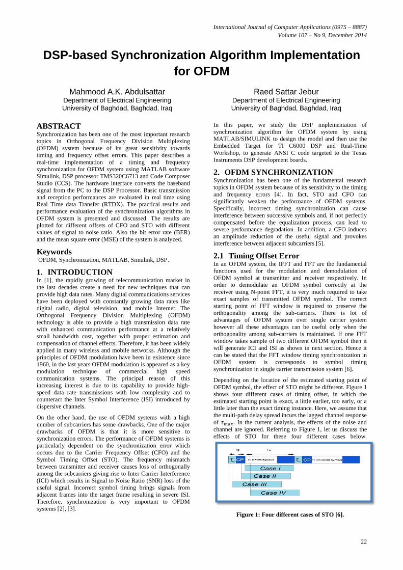
In this algorithm 2N + L samples are observed as shown in
Figure 2. In this interval, it is assumed that there is one
complete OFDM symbol with its cyclic prefix. If we define
r(k) as the set of samples contained in the observed interval, θ
as the index of the start of the symbol and ϵ as the frequency
offset, we can find the maximum likelihood estimate (MLE)
of θ and ϵ by maximizing their log-likelihood function, which
is defined as the logarithm of the probability density function
f(r|θ,ϵ) of the 2N + L samples in r(k) given θ and ϵ.
Figure 2: Structure of OFDM signal with cyclically
extended symbols.
The joint ML estimation becomes
| | (3)
( ) (4)
Where
∑
(5)
∑ | | | |
(6)
(7)
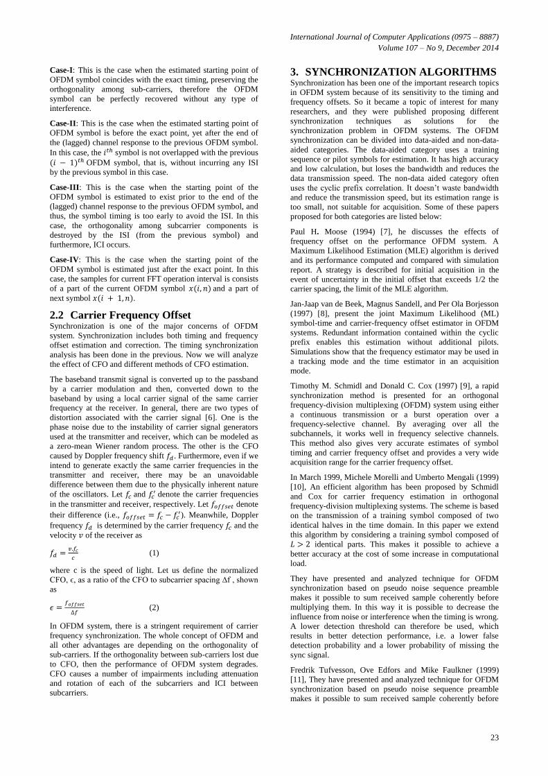
In Figure 3 we can see the scheme for this synchronization
method.
Figure 3: Structure of the estimator.
The algorithm consists of two main branches. The top one
calculates an energy term. While the bottom one calculates the
correlation term required for estimating both symbol arrival
time and phase offset. Equation (6) shows the calculation of
the energy term and Equation (5) shows the calculation of the
correlation term. The factor ρ is the magnitude of the
correlation coefficient between and ; it depends on the
signal-to-noise ratio but can be set to 1. Figure 4 shows the
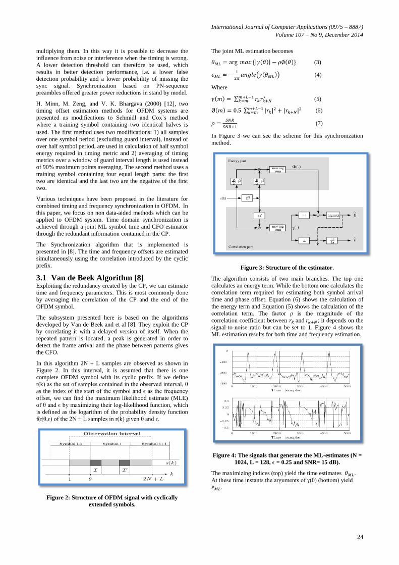
ML estimation results for both time and frequency estimation.
Figure 4: The signals that generate the ML-estimates (N =
1024, L = 128, ϵ = 0.25 and SNR= 15 dB).
The maximizing indices (top) yield the time estimates .
At these time instants the arguments of γ(θ) (bottom) yield
.
International Journal of Computer Applications (0975 – 8887)
Volume 107 – No 9, December 2014
25
4. DIGITAL SIGNAL PROCESSING DSP is one of the fastest growing fields of technology and
computer science in the world. In today's world almost
everyone uses DSPs in their everyday life but, unlike PC
users, almost no one knows that he/she is using DSPs. DSPs
are special purpose microprocessors used in all kind of
electronic products, from mobile phones, modems and CD
players to the automotive industry; medical imaging systems
to the electronic battlefield and from dish washers to satellites
[13].
There are many reasons why we process these analog signals
in the digital world. Traditional signal processing was
achieved by using analogue components such as resistors,
capacitors and inductors. However, the inherent tolerance
associated with these components, temperature and voltage
changes and mechanical vibrations can dramatically affect the
effectiveness of analogue circuitry. On the other hand, DSP is
inherently stable, reliable and repeatable. With DSP it is easy
to chance, correct or updates applications. Additionally, DSP
reduces noise susceptibility, chip count, development time,
cost and power consumption [14].
4.1 TMS320C6713 DSP Description [15],
[16] The TMS320C67 DSPs (including the TMS320C6713 device)
compose the floating point DSP generation in the
TMS320C6000 DSP platform. The TMS320C6713 (C6713)
device is based on the high-performance, Very Long
Instruction Word (VLIW) architecture developed by Texas
Instruments, making this DSP an excellent choice for
multichannel and multifunction applications.
The features of the C6713, 225 MHz device delivering up
to1800 MIPs. This DSP generation is designed for
applications that require high precision accuracy. The C6713
is based on the TMS320C6000 DSP platform designed to fit
the needs of high-performing high-precision applications such
as pro-audio, medical and diagnostic. Other hardware features
of the C6713 board include:
• Embedded JTAG support via USB
• High-quality 24-bit stereo codec
• Four 3.5mm audio jacks for microphone, line in,
speaker and line out
• 512K words of Flash and 8 MB SDRAM
• Expansion port connector for plug-in modules
• On-board standard IEEE JTAG interface
• +5V universal power supply
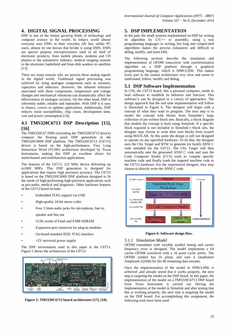
The DSP environment used in this paper is the C6713.
Figure 5 shows the architecture of the C6713.
Figure 5: TMS320C6713 board architecture [17], [18].
5. DSP IMPLEMENTATION In the past, the small systems implemented on DSP by writing
its algorithm by C/C++ or assembly, using a text
programming languages in writing, but long and complicated
algorithms makes the process exhaustive and difficult to
debug, modify, and learn [40].
The following sections describe the simulation and
implementation of OFDM transceiver with synchronization
algorithm on a DSP platform through a graphical
programming language, which is SIMULINK. This makes
every part in the system architecture very clear and easier to
understand, follow, modify and debug.
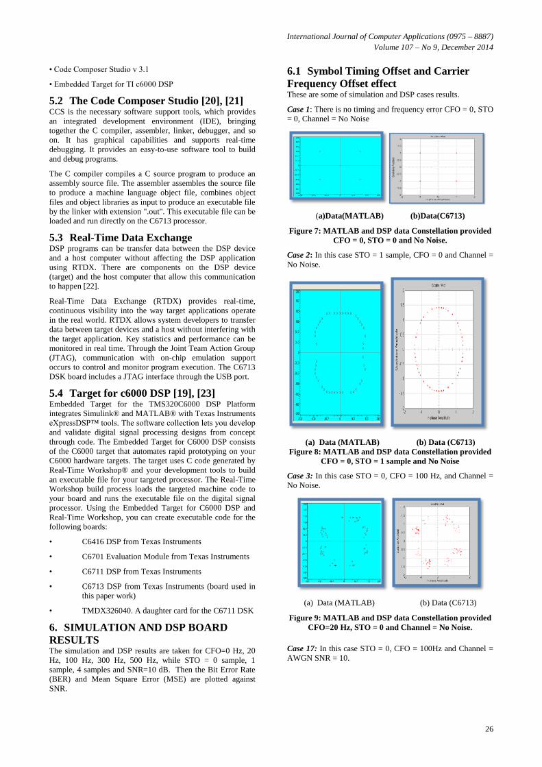
5.1 DSP Software Implementation In [19], the C6713 board, like a personal computer, needs to
load software to establish its behavior and function. This
software’s can be designed in a variety of approaches. The
design approach that the real time implementation will follow
is illustrated in Figure 6. The designer will begin with a
concept of what they want to program. The next step is to
model the concept with blocks from Simulink’s large
collection of pre written block sets. Basically, a block diagram
that models the concept is built using Simulink. If a specific
block required is not included in Simulink’s block sets, the
designer may choose to write their own blocks from scratch
using MATLAB. At this point the design is still not designed
to operate on any specified hardware. To do that, the designer
uses the C6x Target and RTW to generate (or build) ANSI C
code intended for the C6713. The C6x Target will then
automatically take the generated ANSI C code and uses the
Code Composer Studio (CCS) tools to compile specific
machine code and finally loads the targeted machine code to
the C6713 hardware. For the experienced designer, they may
choose to directly write the ANSI C code.
Figure 6: Software design flow.
5.1.1 Simulation Model OFDM transmitter with variable symbol timing and carrier
frequency error is designed. The model implements a 64
carrier OFDM waveform with a 16 point cyclic prefix. The
OFDM symbol has 16 pilots, and uses 4 Quadrature
Amplitude (QAM) for the 48 remaining data streams.
Once the implementation of the model in SIMULINK is
achieved ,and already tested that it works properly, the next
step is targeting the model on the DSP board. In this paper, the
implementation of the model on a TMS320C6713 DSP board
from Texas Instrument is carried out. Having the
implementation of the model in Simulink and after testing that
this is working properly, the next step is targeting the model
on the DSP board. For accomplishing this assignment, the
following tools have been used:
International Journal of Computer Applications (0975 – 8887)
Volume 107 – No 9, December 2014
26
• Code Composer Studio v 3.1
• Embedded Target for TI c6000 DSP
5.2 The Code Composer Studio [20], [21] CCS is the necessary software support tools, which provides
an integrated development environment (IDE), bringing
together the C compiler, assembler, linker, debugger, and so
on. It has graphical capabilities and supports real-time
debugging. It provides an easy-to-use software tool to build
and debug programs.
The C compiler compiles a C source program to produce an
assembly source file. The assembler assembles the source file
to produce a machine language object file, combines object
files and object libraries as input to produce an executable file
by the linker with extension ".out". This executable file can be
loaded and run directly on the C6713 processor.
5.3 Real-Time Data Exchange DSP programs can be transfer data between the DSP device
and a host computer without affecting the DSP application
using RTDX. There are components on the DSP device
(target) and the host computer that allow this communication
to happen [22].
Real-Time Data Exchange (RTDX) provides real-time,
continuous visibility into the way target applications operate
in the real world. RTDX allows system developers to transfer
data between target devices and a host without interfering with
the target application. Key statistics and performance can be
monitored in real time. Through the Joint Team Action Group
(JTAG), communication with on-chip emulation support
occurs to control and monitor program execution. The C6713
DSK board includes a JTAG interface through the USB port.
5.4 Target for c6000 DSP [19], [23] Embedded Target for the TMS320C6000 DSP Platform
integrates Simulink® and MATLAB® with Texas Instruments
eXpressDSP™ tools. The software collection lets you develop
and validate digital signal processing designs from concept
through code. The Embedded Target for C6000 DSP consists
of the C6000 target that automates rapid prototyping on your
C6000 hardware targets. The target uses C code generated by
Real-Time Workshop® and your development tools to build
an executable file for your targeted processor. The Real-Time
Workshop build process loads the targeted machine code to
your board and runs the executable file on the digital signal
processor. Using the Embedded Target for C6000 DSP and
Real-Time Workshop, you can create executable code for the
following boards:
• C6416 DSP from Texas Instruments
• C6701 Evaluation Module from Texas Instruments
• C6711 DSP from Texas Instruments
• C6713 DSP from Texas Instruments (board used in
this paper work)
• TMDX326040. A daughter card for the C6711 DSK
6. SIMULATION AND DSP BOARD
RESULTS The simulation and DSP results are taken for CFO=0 Hz, 20
Hz, 100 Hz, 300 Hz, 500 Hz, while STO = 0 sample, 1
sample, 4 samples and SNR=10 dB. Then the Bit Error Rate
(BER) and Mean Square Error (MSE) are plotted against
SNR.
6.1 Symbol Timing Offset and Carrier
Frequency Offset effect These are some of simulation and DSP cases results.
Case 1: There is no timing and frequency error CFO = 0, STO
= 0, Channel = No Noise
(a)Data(MATLAB) (b)Data(C6713)
Figure 7: MATLAB and DSP data Constellation provided
CFO = 0, STO = 0 and No Noise.
Case 2: In this case STO = 1 sample, CFO = 0 and Channel =
No Noise.
(a) Data (MATLAB) (b) Data (C6713)
Figure 8: MATLAB and DSP data Constellation provided
CFO = 0, STO = 1 sample and No Noise
Case 3: In this case STO = 0, CFO = 100 Hz, and Channel =
No Noise.
(a) Data (MATLAB) (b) Data (C6713)
Figure 9: MATLAB and DSP data Constellation provided
CFO=20 Hz, STO = 0 and Channel = No Noise.
Case 17: In this case STO = 0, CFO = 100Hz and Channel =
AWGN SNR = 10.
International Journal of Computer Applications (0975 – 8887)
Volume 107 – No 9, December 2014
27
(a) Data (MATLAB) (b) Data (C6713)
Figure 10: MATLAB and DSP data Constellation
provided CFO = 100 Hz, STO = 0 and Channel = AWGN
SNR = 10.
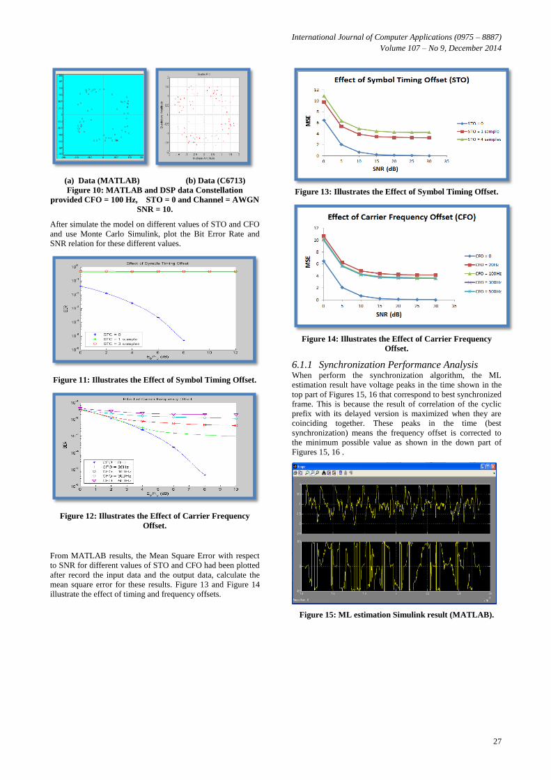
After simulate the model on different values of STO and CFO
and use Monte Carlo Simulink, plot the Bit Error Rate and
SNR relation for these different values.
Figure 11: Illustrates the Effect of Symbol Timing Offset.
Figure 12: Illustrates the Effect of Carrier Frequency
Offset.
From MATLAB results, the Mean Square Error with respect
to SNR for different values of STO and CFO had been plotted
after record the input data and the output data, calculate the
mean square error for these results. Figure 13 and Figure 14
illustrate the effect of timing and frequency offsets.
Figure 13: Illustrates the Effect of Symbol Timing Offset.
Figure 14: Illustrates the Effect of Carrier Frequency
Offset.
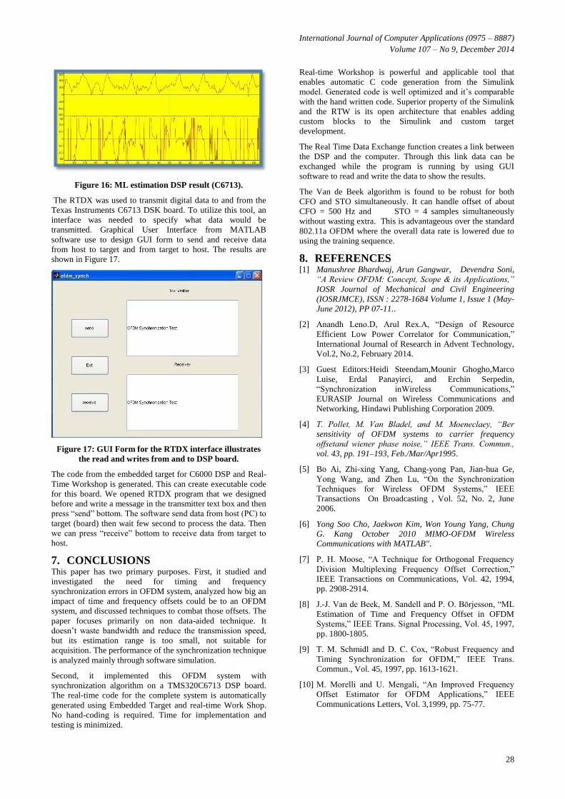
6.1.1 Synchronization Performance Analysis When perform the synchronization algorithm, the ML
estimation result have voltage peaks in the time shown in the
top part of Figures 15, 16 that correspond to best synchronized
frame. This is because the result of correlation of the cyclic
prefix with its delayed version is maximized when they are
coinciding together. These peaks in the time (best
synchronization) means the frequency offset is corrected to
the minimum possible value as shown in the down part of
Figures 15, 16 .
Figure 15: ML estimation Simulink result (MATLAB).
International Journal of Computer Applications (0975 – 8887)
Volume 107 – No 9, December 2014
28
Figure 16: ML estimation DSP result (C6713).
The RTDX was used to transmit digital data to and from the
Texas Instruments C6713 DSK board. To utilize this tool, an
interface was needed to specify what data would be
transmitted. Graphical User Interface from MATLAB
software use to design GUI form to send and receive data
from host to target and from target to host. The results are
shown in Figure 17.
Figure 17: GUI Form for the RTDX interface illustrates
the read and writes from and to DSP board.
The code from the embedded target for C6000 DSP and Real-
Time Workshop is generated. This can create executable code
for this board. We opened RTDX program that we designed
before and write a message in the transmitter text box and then
press “send” bottom. The software send data from host (PC) to
target (board) then wait few second to process the data. Then
we can press “receive” bottom to receive data from target to
host.
7. CONCLUSIONS This paper has two primary purposes. First, it studied and
investigated the need for timing and frequency
synchronization errors in OFDM system, analyzed how big an
impact of time and frequency offsets could be to an OFDM
system, and discussed techniques to combat those offsets. The
paper focuses primarily on non data-aided technique. It
doesn’t waste bandwidth and reduce the transmission speed,
but its estimation range is too small, not suitable for
acquisition. The performance of the synchronization technique
is analyzed mainly through software simulation.
Second, it implemented this OFDM system with
synchronization algorithm on a TMS320C6713 DSP board.
The real-time code for the complete system is automatically
generated using Embedded Target and real-time Work Shop.
No hand-coding is required. Time for implementation and
testing is minimized.
Real-time Workshop is powerful and applicable tool that
enables automatic C code generation from the Simulink
model. Generated code is well optimized and it’s comparable
with the hand written code. Superior property of the Simulink
and the RTW is its open architecture that enables adding
custom blocks to the Simulink and custom target
development.
The Real Time Data Exchange function creates a link between
the DSP and the computer. Through this link data can be
exchanged while the program is running by using GUI
software to read and write the data to show the results.
The Van de Beek algorithm is found to be robust for both
CFO and STO simultaneously. It can handle offset of about
CFO = 500 Hz and STO = 4 samples simultaneously
without wasting extra. This is advantageous over the standard
802.11a OFDM where the overall data rate is lowered due to
using the training sequence.
8. REFERENCES [1] Manushree Bhardwaj, Arun Gangwar, Devendra Soni,
“A Review OFDM: Concept, Scope & its Applications,”
IOSR Journal of Mechanical and Civil Engineering
(IOSRJMCE), ISSN : 2278-1684 Volume 1, Issue 1 (May-
June 2012), PP 07-11..
[2] Anandh Leno.D, Arul Rex.A, “Design of Resource
Efficient Low Power Correlator for Communication,”
International Journal of Research in Advent Technology,
Vol.2, No.2, February 2014.
[3] Guest Editors:Heidi Steendam,Mounir Ghogho,Marco
Luise, Erdal Panayirci, and Erchin Serpedin,
“Synchronization inWireless Communications,”
EURASIP Journal on Wireless Communications and
Networking, Hindawi Publishing Corporation 2009.
[4] T. Pollet, M. Van Bladel, and M. Moeneclaey, “Ber
sensitivity of OFDM systems to carrier frequency
offsetand wiener phase noise,” IEEE Trans. Commun.,
vol. 43, pp. 191–193, Feb./Mar/Apr1995.
[5] Bo Ai, Zhi-xing Yang, Chang-yong Pan, Jian-hua Ge,
Yong Wang, and Zhen Lu, “On the Synchronization
Techniques for Wireless OFDM Systems,” IEEE
Transactions On Broadcasting , Vol. 52, No. 2, June
2006.
[6] Yong Soo Cho, Jaekwon Kim, Won Young Yang, Chung
G. Kang October 2010 MIMO-OFDM Wireless
Communications with MATLAB".
[7] P. H. Moose, “A Technique for Orthogonal Frequency
Division Multiplexing Frequency Offset Correction,”
IEEE Transactions on Communications, Vol. 42, 1994,
pp. 2908-2914.
[8] J.-J. Van de Beek, M. Sandell and P. O. Börjesson, “ML
Estimation of Time and Frequency Offset in OFDM
Systems,” IEEE Trans. Signal Processing, Vol. 45, 1997,
pp. 1800-1805.
[9] T. M. Schmidl and D. C. Cox, “Robust Frequency and
Timing Synchronization for OFDM,” IEEE Trans.
Commun., Vol. 45, 1997, pp. 1613-1621.
[10] M. Morelli and U. Mengali, “An Improved Frequency
Offset Estimator for OFDM Applications,” IEEE
Communications Letters, Vol. 3,1999, pp. 75-77.
International Journal of Computer Applications (0975 – 8887)
Volume 107 – No 9, December 2014
29
[11] F. Tufvesson, O. Edfors and M. Faulkner, “Time and
Frequency Synchronization for OFDM using PN-
sequence Preamble,” in Proc. Veh. Technol. Conf., Vol.
4, 1999, pp. 2203-2207.
[12] H. Minn, M. Zeng and V. K. Bhargava, “On Timing Off-
set Estimation for OFDM Systems,” IEEE Commun. Let-
ters, Vol. 4, 2000, pp. 242-244.
[13] Özlem Kalinli. “Signal Processing with DSPs”.
Undergraduation Thesis. June-2001.
[14] B. Preetham Kumar, “DIGITAL SIGNAL
PROCESSING LABORATORY,” A CRC title, part of
the Taylor & Francis imprint, 2005 by CRC Press.
[15] Milind U. Nemade, Satish K.Shah, “ Real Time Speech
Recognition Using DSK TMS320C6713,” International
Journal of Advanced Research in Computer Science and
Software Engineering, Volume 4, Issue 1, January 2014.
[16] Texas Instrument Inc., “TMS320C6713 Floting-Point
Digital Signal Processor” SPRS186L ,November 2005.
[17] Azeddine Wahbi, Ahmed Roukhe, Laamari Hlou,”
Conception and Real Time DSK C6713 of a Low Cost
Adaptive Acoustic Noise Cancellation (ANC) Based Fast
Fourier Transform (FFT) and Circular Convolution for
Improving the Quality of Voice Communications,”
Int.J.Computer Technology & Applications,Vol 5
(2),630-639, March-April 2014.
[18] Azeddine Wahbi, Ahmed Roukhe, Laamari Hlou,
“Modeling and real-time DSK C6713 implementation of
normalized least mean square (NLMS) adaptive
algorithm for acoustic noise cancellation (ANC) in voice
communications,” Journal of Theoretical and Applied
Information Technology, 20 Th July 2014. Vol. 65 No.2.
[19] R. Chassaing and D. Reay," Digital Signal Processing
and Application with the TMS320C6713 and
TMS320C6416 DSK" Second Edition, John Wily &
Sons, Inc., 2005.
[20] Nasser Kehtarnavaz and Namjin Kim, “Real-Time
Digital Signal Processing Based on the TMS320C6000,”
Linacre House, Jordan Hill, Oxford OX2 8DP, UK 2005.
[21] Dr. Seema Verma, Pawan Sharma, “Hardware
Implementation of OFDM system on TMS320C6713 and
verifying the results by using DIP Switches and LEDs,”
IPASJ International Journal of Electronics &
Communication (IIJEC), Volume 1, Issue 6, December
2013.
[22] Embedded Target for the TI TMS320C6000 DSP
Platform (For use with Real-Time Workshop (Version
1)). July 2002.
[23]
IJCATM : www.ijcaonline.org