Embed Size (px)
Citation preview
drylin.E...®
...www.igus.eu/eu/drylinE...
Lubrication-free linear actuator with motor
...05.2013...plastics for longer life®...®

3
“E” as in Electric and is the latest development and addition to the modular drylin linear guide range. The lubricant-free linear guides guarantee clean and dirt-resistant operation. Ready-to-fit linear actuators and drive systems can be fitted with either leadscrew drives or belts. The range of accessories includes handwheels, position indi-cator, v-drives, couplings and much more. The drylin® E product range is complete with hybrid stepper motors, connectors, encoders, and the proven chainflex® power cables from igus®.
Delivery time: 3-4 days 100% lubricant-free linear guide Cost-effective and online configuration possible
2
tooth belt, trapezoidal or high helix thread
Ball bearings leadscrew supports
Motor flange: connection for stepper motors
Claw coupling
igus® motors Stepper and DC motors Cost-effective 25 versions High protection class or Low-Cost-design
liners made of maintenance-free iglidur® J
www.igus.eu/eu/drylinE3–4 days www.igus.eu/drylinE-applications
drylin® E
...electric... ...applications...drylin® E – application examples
Camera adjustmentA quiet, vibration- and lubrication-free operation is required in this camera adjustment on a conveyor belt using a drylin® ZLW toothed belt axis.
Sampler/pipetteSpace-saving telescope adjustment using a compact and lubrication-free drylin® ZLW toothed belt drives. (Sierra Sensors GmbH)
Adjustment of inspection equipmentdrylin® ZLW toothed belt drive in an inspection camera adjustment for checking the position of sealing rings.(OLPE Jena GmbH)
Sensor adjustment/Measuring systemsdrylin® ZLW-0630 toothed belt actuators in an X-Y configura-tion for adjusting a laser detector head. Compact, lightweight and maintenance-free due to polymer plain bearings.
Pick and PlaceQuick and maintenance-free handling with drylin® toothed belt axes as a room portal (X, Y, Z axis).
Handling of small partsThe tough and lubrication-free structure of the ZLW and dry-lin® W profiles allows a long and maintenance-free life.
Lubrication-free linear guide system using polymer bearings

4 5
www.igus.eu/eu/drylinE-ZLW
The drylin® product portfolio provides lubricant-free linear drives that are driven either by a trapezoidal thread, high helix thread or toothed belt. The user can choose a suitable individual solution from lightweight solid plastic units up to heavy duty stainless steel solutions. In all systems, the stroke length is freely selectable and the drive implemented either via handwheel or motor.
When to use it? Quick positioning of small loads Quiet running Flat design Long-term usage
When not to use it? For high dynamic loads When positioning accuracy < 0.1 mm is
necessary
www.igus.eu/eu/drylinE-SAW
www.igus.eu/eu/drylinSHT www.igus.eu/eu/drylinSLW
...100% lubrication-free...drylin® linear technology: leadscrew and tooth belt actuators
Linear actuators with belt drive
Ball bearings leadscrew supports
Lubrication-free linear guide system using polymer bearing
different carriage lengths
Hard-anodized aluminum profile
Polyurethane or neoprene toothed belts
When to use it? For format adjustments and positioning
of medium loads In extreme environments When a cost-effective, ready-to-fit
solution is required For low noise applications
When not to use it? When high loads combined with very
high speeds When positioning accuracy < 0.1 mm
is necessary If high running performance is required in
continuous operation
Polymer bearings and leadscrew nuts give lubrication-free operation
Linear actuators with leadscrew
Three shaft materials
8 trapezoidal thread pitches,4 high helix thread pitches
Base body material: Stainless steel, aluminum,
zinc or plastic
drylin® linear technology
ZLW-0630 Max. stroke length:
1,000 mm Load: max. 15 kg Dimensions: 54 x 31 mm
ZLW-1040 Max. stroke length:
3,000 mm Load: max. 30 kg Dimensions: 74 x 45 mm
ZLW-1660 Max. stroke length:
3,000 mm Load: max. 100 kg Dimensions: 104 x 72 mm
tooth belt drive with motor
Leadscrew actuators with motor
SAW-0630 Max. stroke length: 300 mm Load: max. 40 kg Dimensions: 54 x 32 mm Leadscrew pitches: 1,5 & 15
SAW-1040 Max. stroke length: 500 mm Load: max. 200 kg Dimensions: 74 x 50 mm Leadscrew pitches: 2, 3, 12 & 50
Other drylin® leadscrew-linear-tables
SHT design Flat design High precision Three sizes Optional with motor and accessories
SLW design Flat design High stiffness Five sizes Optional with motor and accessories

6 7
igus® motors Stepper and DC motors 25 versions High protection class or
Low-Cost-design
connector cables For motors Encoder, brake and
connectors 24 versions from stock
motor flanges To connect with igus®
stepper motors or customized motors
couplings 50 versions from stock Vibration-dampening and
flexible
position switches High protection class Precision fit to the linear
guide rail
www.igus.eu/drylinE-motordata
...with motor...drylin® E NEMA stepper motors: versions
Motor with stranded wiresThis motor is the least expensive and the most popular option. The connecting wires for this type come directly from the housing. They are preferably installed in machines and equipment that have an additional housing or are used in clean environments.
Motor with connector plugFitted with connector plug, it reaches protec-tion class IP65 (IP: International Protection). The higher the IP protection class, the better the pro-tection against dirt and humidity.
Motor with connector plug and encoderThe encoder sends signals from the motor to the control unit. With the encoder the preciselinear motion of the drylin® unit can be cont-rolled. Encoder = higher reliability of the equip-ment.
Motor with plug, encoder and brakeThe brake can hold the load in place whenthe motor is stopped. This is used as a safetyfeature in case of power cuts – recommended for vertically installed systems.
NEMA17: The small one with lots of powerThis little motor can be impressive with good torque and high speeds. Reliable, rapid movements of smaller loads.
The holding torque Mo is 0,5 Nm The mating face is 42 x 42 mm
NEMA23: The most popular stepper motor sizeHigh torque and high speed are the main advantages. This motor is the best choice for most applications in the medium load range.
The holding torque Mo is 2,0 Nm The mating face is 56 x 56 mm
NEMA23XL:The power motor, medium sizeAn advanced development of the typical NEMA23 with approximately double the torque. The mounting dimensions are the same as in the NEMA23, so that it can be used on the same mounting face.
The holding torque Mo is 3,5 Nm The mating face is 60 x 60 mm
NEMA34: Large size, power packageApplications with high loads should use this large type. Heavy duty or parallel twin rail superstructures are typical working environment.
The holding torque Mo is 5,9 Nm The mating face is 86 x 86 mm
drylin® E NEMA stepper motors: sizes
drylin® E accessories

8 9
drylin® E – configurate and order individually calculate, compare and select the right drive units
...design kit... ...find online...
SAW
ZLW
www.igus.eu/eu/drylinE-finder
In addition to calculating the correct linear unit, the product finder for drylin® drive technology also provides for the option to calculate the cor-rect motors, incl. service life. The identified so-lutions can be directly configured and ordered using the same tool.
Linear solutions tailored to your application, incl. motor
if desired
Configurable accessories and order function
When selecting motor incl. load calculation
Easy to understand results screen to select the ideal
solution
Convenient access to other functions, such as online
catalog, shopping cart, downloads, etc.
“Search”drylin® product finder for linear slide tablesJust enter useful application-data and compare adequateLinear Slide Tables online and then configure.
www.igus.eu/sht-productfinder
linear axis flange coupling motor
“Configure”
“Ready”Linear actuators with motor
Lightweight Cost-effective 100 % lubrication-free Mor than 50 versions
available from stock in 3-4 days

10 11
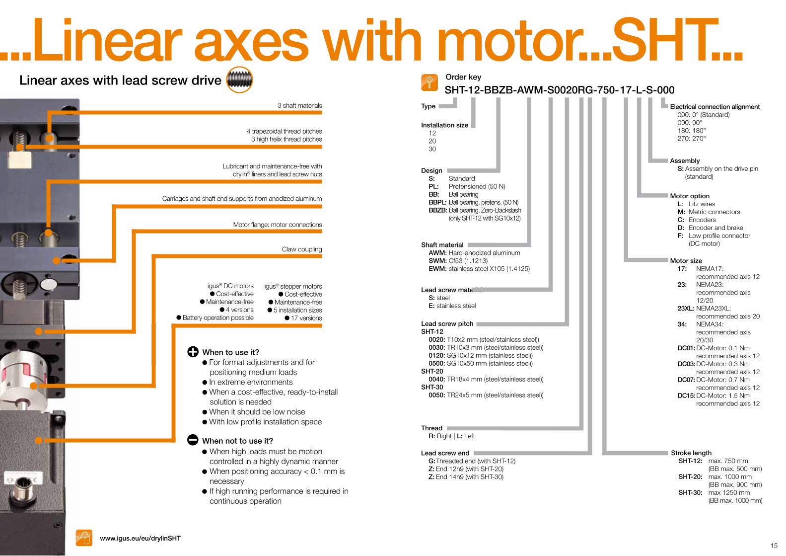
...Linear axes with motor...SAW...Linear axes with lead screw drive Order key
When to use it? For format adjustments and to position medium loads In extreme environments When a cost-effective, ready-to-install solution is needed When it should be low noise For unsupported installations
When not to use it? When high loads need to travel at highly dynamic
forces When positioning accuracy < 0.1 mm is required When high running performance is required in
continuous operation
Lubricant and maintenance-freedrylin® W linear guide systems
4 trapezoidal thread pitches3 high helix thread pitches
Shaft end support from aluminum or plastics
Motor flange:motor connections
Claw coupling
Hard anodized drylin® Waluminum profile (high profile shape)
igus® DC motors Cost-effective
Maintenance-free 4 versions
Battery operation possible
igus® stepper motors Cost-effective
Maintenance-free 5 installation sizes
17 versions
DesignSAW-0630 S: Standard M: Mono carriage (plastic)SAW-1040/1660 S: Standard E: Adjustable linear bearing PL: Pretensioned (50N) EPL: Adjustable, pretensioned (50 N)
Thread R: Right | L: Left
Lead screw pitchSAW-0630 0015: TR8x1,5 mm (steel) 0150: SG8x15 mm (stainless steel)SAW-1040 0020: TR10x2 mm (steel/stainless steel) 0030: TR10x3 mm (steel/stainless steel) 0120: SG10x12 mm (stainless steel) 0500: SG10x50 mm (stainless steel)SAW-1660 0040: TR14x4 mm (steel/stainless steel)
SAW-1040-EPL-07-S0020RG-450-17-M-S-000
Electrical connection alignment 000: 0° (Standard) 090: 90° 180: 180° 270: 270°
Assembly S: Assembly on the drive pin
(standard)
Motor option L: Litz wires M: Metric connectors C: Encoders D: Encoder and brake F: Low profile connector
(DC-Motor)
Motor size 17: NEMA17: recommended axis 0630 23: NEMA23: recommended axis 1040 23XL: NEMA23XL: recommended axis 1040 DC01: DC-Motor: 0,1 Nm recommended axis 0630 DC03: DC-Motor: 0,3 Nm recommended axis 0630/1040 DC07: DC-Motor: 0,7 Nm recommended axis 0630 DC15: DC-Motor: 1,5 Nm recommended axis 1040/1660
Stroke length SAW-0630: max. 300 mm SAW-1040: max. 500 mm SAW-1660: max 750 mm
Lead screw end G: Threaded end
Lead screw material: S: steel E: stainless steel
Carriage lengthSAW-0630 06: 60 mm (Standard)SAW-1040 07: 69 mm (Standard) 10: 100 mm 15: 150 mmSAW-1660 15: 150 mm (Standard)
Type
Installation size 0630 1040 1660
www.igus.eu/eu/drylinSAW

12 13
When to use it? For format adjustments and to position medium loads In extreme environments When a cost-effective, ready-to-install solution is needed When it should be low noisel When installation space is limited
Lubricant and maintenance-free drylin® W linear profile guides
4 trapezoidal thread pitches3 high helix thread pitches
Shaft end supports are made from anodized aluminum or from plastics
Motor flange:motor connections
Claw coupling
Hard anodized drylin® Waluminum profile (plain profile shape)
igus® DC motors Cost-effective
Maintenance-free 4 versions
Battery operation possible
When not to use it? When high loads must be motion
controlled in a highly dynamic manner When positioning accuracy < 0.1 mm is
necessary When high running performance is
required in continuous operation
igus® stepper motors Cost-effective
Maintenance-free 5 installation sizes
17 versions
www.igus.eu/eu/drylinSLW
DesignSLW-0630 BB: SLW-1040/1080/1660/2080 S: E: PL: EPL: BB: BBE: BBPL: BBEPL:
Ball bearing
StandardAdjustable linear bearingPretensioned (50N)Adjustable, pretensioned (50 N)Ball bearingBall bearing, Adjustable linear bearingBall bearing, pretensioned (50 N)Ball bearing, Adjustable linear bearing, pretensioned (50N)
Thread R: Right | L: Left
Lead screw pitchSLW-0630 0015: TR8x1,5 mm (steel) 0150: SG8x15 mm (stainless steel)SLW-1040/1080 0020: TR10x2 mm (steel/stainless steel) 0030: TR10x3 mm (steel/stainless steel) 0120: SG10x12 mm (stainless steel) 0500: SG10x50 mm (stainless steel)SLW-1660 0040: TR14x4 mm (steel/stainless steel)SLW-2080 0040: TR18x4 mm (steel/stainless steel)
SLW-1040-EPL-07-S 0020 R G-750-17-L-S-000Order key
Electrical connection alignment 000: 0° (Standard) 090: 90° 180: 180° 270: 270°
Assembly S: Assembly on the drive pin
(standard)
Motor option L: Litz wires M: Metric connectors C: Encoders D: Encoder and brake F: Low profile connector
(DC motor)
Motor size/Recommended axis 17: NEMA17 / 0630 23: NEMA23 / 1040, 1080 23XL: NEMA23XL / 1040, 1080, 1660 34: NEMA 34 / 2080 DC01: DC-Motor: 0,1 Nm / 0630 DC03: DC-Motor: 0,3 Nm / 0630, 1040 DC07: DC-Motor: 0,7 Nm / 1040 DC15: DC-Motor: 1,5 Nm / 1040, 1660
Stroke length SLW-0630: max. 300 mm SLW-1040/1080: max. 750 mm (BB: max.500 mm) SLW-1660: max 750 mm SLW-2080: max 1000 mm (BB: 900 mm)
Lead screw end G: Threaded end Z: End 12h9 (with SLW-2080)
Lead screw material S: steel E: stainless steel
Carriage lengthSLW-0630 06: 60 mm (Standard)SLW-1040 07: 69 mm (Standard) 10: 100 mm 15: 150 mmSLW-1080/1660/2080 15: 150 mm (Standard)
Type
Installation size 0630 1040/1080 1660 2080
...Linear axes with motor...SLW...Linear axes with lead screw drive
14 15
Order key
When to use it? For format adjustments and for positioning medium loads In extreme environments When a cost-effective, ready-to-install solution is needed When it should be low noise With low profile installation space
4 trapezoidal thread pitches3 high helix thread pitches
Carriages and shaft end supports from anodized aluminum
Lubricant and maintenance-free withdrylin® liners and lead screw nuts
Motor flange: motor connections
Claw coupling
3 shaft materials
igus® DC motors Cost-effective
Maintenance-free 4 versions
Battery operation possible
When not to use it? When high loads must be motion
controlled in a highly dynamic manner When positioning accuracy < 0.1 mm is
necessary If high running performance is required in
continuous operation
igus® stepper motors Cost-effective
Maintenance-free 5 installation sizes
17 versions
www.igus.eu/eu/drylinSHT
Design S: Standard PL: Pretensioned (50 N) BB: Ball bearing BBPL: Ball bearing, pretens. (50 N) BBZB: Ball bearing, Zero-Backslash (only SHT-12 with SG10x12)
Thread R: Right | L: Left
Lead screw pitchSHT-12 0020: T10x2 mm (steel/stainless steel)) 0030: TR10x3 mm (steel/stainless steel)) 0120: SG10x12 mm (stainless steel)) 0500: SG10x50 mm (stainless steel))SHT-20 0040: TR18x4 mm (steel/stainless steel))SHT-30 0050: TR24x5 mm (steel/stainless steel))
SHT-12-BBZB-AWM-S0020RG-750-17-L-S-000Electrical connection alignment 000: 0° (Standard) 090: 90° 180: 180° 270: 270°
Assembly S: Assembly on the drive pin (standard)
Motor option L: Litz wires M: Metric connectors C: Encoders D: Encoder and brake F: Low profile connector (DC motor)
Motor size 17: NEMA17: recommended axis 12 23: NEMA23: recommended axis 12/20 23XL: NEMA23XL: recommended axis 20 34: NEMA34: recommended axis 20/30 DC01: DC-Motor: 0,1 Nm recommended axis 12 DC03: DC-Motor: 0,3 Nm recommended axis 12 DC07: DC-Motor: 0,7 Nm recommended axis 12 DC15: DC-Motor: 1,5 Nm recommended axis 12
Stroke length SHT-12: max. 750 mm (BB max. 500 mm) SHT-20: max. 1000 mm (BB max. 900 mm) SHT-30: max 1250 mm (BB max. 1000 mm)
Lead screw end G: Threaded end (with SHT-12) Z: End 12h9 (with SHT-20) Z: End 14h9 (with SHT-30)
Lead screw material: S: steel E: stainless steel
Shaft material AWM: Hard-anodized aluminum SWM: Cf53 (1.1213) EWM: stainless steel X105 (1.4125)
Type
Installation size 12 20 30
...Linear axes with motor...SHT...Linear axes with lead screw drive

16 17
Linear axes with toothed belt Order key
www.igus.eu/eu/drylinZLW
Deflection with grooved ball bearings
Lubricant and maintenance-freedrylin® W linear profile guides
Hard anodized drylin® W aluminumprofile (high profile shape)
Various Carriage lengths
Polyurethane orneoprene toothed belts
When to use it? Quick positioning of small loads Quiet operation Slim structure Continuous operation
When not to use it? When high loads must be motion controlled in a highly dynamic manner When positioning accuracy < 0.1 mm is necessary
igus® DC motors Cost-effective
Maintenance-free 4 versions
Battery operation possible
Motor flange:motor connections
Claw coupling
igus® stepper motors Cost-effective
Maintenance-free 5 installation sizes
17 versions
ZLW-1040-02-B-60-L-750-17-M-S-000
Motor size 17: NEMA17: recommended axis 0630 23: NEMA23: recommended axis 1040 23XL: NEMA23XL: recommended axis 1040 34: NEMA34: recomm. axis 1040/1660 DC01: DC-Motor 0,1 Nm: recommended axis 0630 DC03: DC-Motor: 0,3 Nm: recommended axis 0630 DC07: DC-Motor: 0,7 Nm recommended axis 1040 DC15: DC-Motor: 1,5 Nm recommended axis 1040
Electrical connection alignment 000: 0° (Standard) 090: 90° 180: 180° 270: 270°
Assembly S: Assembly with one drive pin (standard)
Motor option L: Litz wires M: Metric connectors C: Encoders D: Encoder and brake F: Low profile connector (DC motor)
Version 02: With grooved ball bearings
Installation size 0630 1040 1660
Type ZLW
Stroke length ZLW-0630: max. 1.000 mm ZLW-1040: max. 2.000 mm ZLW-1660: max. 3.000 mm
Drive pins L: Left-hand drive pin R: Right-hand drive pin L/R: Drive both sides
Carriage length 60: 60 mm (only ZLW 0630) 100: 100 mm 150: 150 mm 200: 200 mm 250: 250 mm
Design S: Type series - standard B: Type series - basic
...Linear axes with motor...ZLW...
18 19
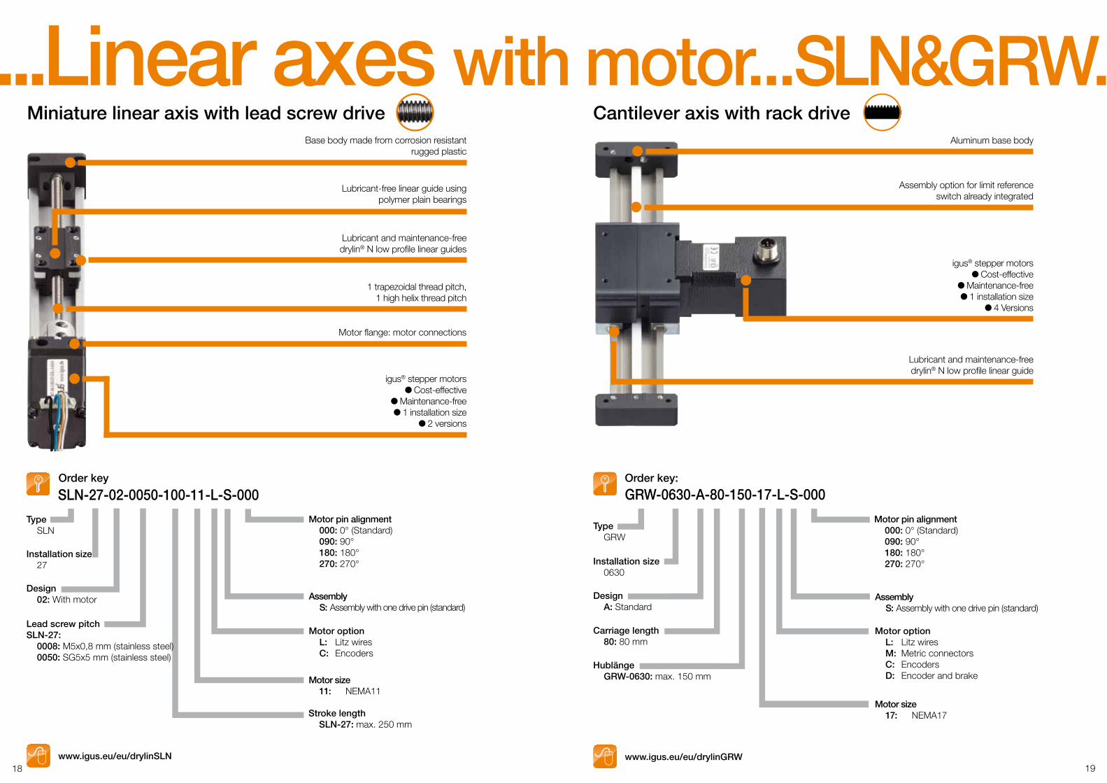
Miniature linear axis with lead screw drive
www.igus.eu/eu/drylinSLN
Cantilever axis with rack driveBase body made from corrosion resistant
rugged plastic
Lubricant-free linear guide usingpolymer plain bearings
Lubricant and maintenance-freedrylin® N low profile linear guides
Motor flange: motor connections
1 trapezoidal thread pitch,1 high helix thread pitch
igus® stepper motors Cost-effective
Maintenance-free 1 installation size
2 versions
SLN-27-02-0050-100-11-L-S-000Order key
Motor pin alignment 000: 0° (Standard) 090: 90° 180: 180° 270: 270°
Assembly S: Assembly with one drive pin (standard)
Installation size 27
Design 02: With motor
Type SLN
Motor option L: Litz wires C: Encoders
Motor size 11: NEMA11
Stroke length SLN-27: max. 250 mm
Lead screw pitchSLN-27: 0008: M5x0,8 mm (stainless steel) 0050: SG5x5 mm (stainless steel)
Aluminum base body
Assembly option for limit referenceswitch already integrated
Lubricant and maintenance-freedrylin® N low profile linear guide
igus® stepper motors Cost-effective
Maintenance-free 1 installation size
4 Versions
GRW-0630-A-80-150-17-L-S-000Order key:
Motor pin alignment 000: 0° (Standard) 090: 90° 180: 180° 270: 270°
Assembly S: Assembly with one drive pin (standard)
Installation size 0630
Design A: Standard
Type GRW
Motor size 17: NEMA17
Hublänge GRW-0630: max. 150 mm
Carriage length 80: 80 mm
Motor option L: Litz wires M: Metric connectors C: Encoders D: Encoder and brake
www.igus.eu/eu/drylinGRW
...Linear axes with motor...SLN&GRW...
/24
In the sector of energy chains®* with cables and assembly as well as plastic plain bearings, igus® is certified according to DIN EN ISO 9001 : 2008and ISO/TS 16949 : 2009*.
/20hOrdering and deliveries weekdays from 7.00 am to 8.00 pm, Saturday from 8.00 am to 12.00 pm. No minimum order quantities, no surcharges. Quick delivery. www.igus.eu Tel. +49-2203 9649-0 Fax -222
dryl
in E
...MAT0071843.20 Stand 05/2013Subject to technical alterations
Online shopping – 24 h! More catalogs and brochures online – www.igus.eu/downloads
igus® GmbH Spicher Straße 1a D-51147 ColognePhone +49 22 03/96 49-145 Fax +49 22 03/96 [email protected] www.igus.eu www.drylin.eu
®
/readyAsk for fully harnessed and preassembled readychains® – increase your cash-flow and profit immediately – www.readychain.eu
ISO9001:2008ISO/TS16949:2009