Embed Size (px)
Citation preview

Specifications are subject to change (26.04.2007) 1
H-line Motor Controller Rotary Ramp profile settingRated operational voltageRated operational currentControl voltageOptions
Ordering Key
Motor ControllersAC Semiconductor Motor ControllerType RSHR 3-Phase
• Soft starting and stopping of 3-phase squirrel cage motors
• Control of all 3 phases• In Line or In Delta motor connection• Low inrush and reduced vibration during starting• External power supply option for a wide operational
voltage range• Rated operational voltage: up to 600 VAC, 50/60 Hz• Rated operational current: up to 32A AC-53a• LED status indicators• Motor PTC protection• Device over-temperature protection• DIN rail mounting** Accessory for panel mounting available
Product DescriptionCompact, digital AC semi-conductor motor controller.When used on a typical400VAC supply, this controllercan soft-start and soft-stop3-phase motors up to 22kW(30HP) when connected InDelta and up to 15kW (20HP)when connected In Line. All3-phases are switched.Starting and stopping time aswell as initial torque can be
independently adjusted bypotentiometers on the facia.A version adapted for startingScroll Compressors is alsoavailable.
This device does not includeinternal bypass relays butprovides a relay contact tohelp energise an externalbypass contactor.
RSHR 48 32 C V33
Type Rated Operational Rated operational Control Voltage Uc OptionsVoltage Ue Current Ie
RSHR: 22: 127/220VACrms, 50/60Hz 25: 25A AC-53a C: 24 - 550VAC/DC V32: In LineH-line motor 40: 230/400VACrms, 50/60Hz 32: 32A AC-53a D: 24 - 660VAC/DC V33: In Deltacontroller with 48: 277/480VACrms, 50/60Hz V34: In Line with external supplyrotary settings 60: 346/600VACrms, 50/60Hz V35: In Delta with external supply
M: 220-480VACrms, 50/60Hz* V38: In Line, Scroll Compressors400-480VACrms, 50/60Hz*
Type Selection
Rated operational Control Voltage Uc Supply Voltage Connection Rated operational current Ie @ 40°C voltage Ue Us 25A AC-53a 32A AC-53a
220VACrms 24-550VAC/DC - In Line RSHR2225CV32 RSHR2232CV32In Delta RSHR2225CV33 RSHR2232CV33
400VACrms 24-550VAC/DC - In Line RSHR4025CV32 RSHR4032CV32In Line RSHR4025CV38 RSHR4032CV38(Scroll Compressors)
- In Delta RSHR4025CV33 RSHR4032CV33480VACrms 24-550VAC/DC - In Line RSHR4825CV32 RSHR4832CV32
- In Delta RSHR4825CV33 RSHR4832CV33600VACrms 24-660VAC/DC - In Line RSHR6025DV32 RSHR6032DV32
- In Delta RSHR6025DV33 RSHR6032DV33400-480VACrms 24-550VAC/DC 24VAC/DC In Line RSHRM25CV34 RSHRM32CV34220-480VACrms 24-550VAC/DC 24VAC/DC In Delta RSHRM25CV35 RSHRM32CV35
Selection Guide
* requires external supply

2 Specifications are subject to change (26.04.2007)
RSHR 3-Phase
RSHR..25.V3. RSHR..32.V3.Assigned motor rating / UL rating @ 40°C
220VACrms 5.5kW / 7.5HP 9kW / 10HP400VACrms 11kW / 10HP 15kW / 20HP480VACrms 11kW / 15HP 18.5kW / 25HP600VACrms 18.5kW / 20HP 22kW / 30HP
Assigned motor rating / UL rating @ 50°C220VACrms 5.5kW / 7.5HP 5.5kW / 7.5HP400VACrms 11kW / 10HP 11kW / 15HP480VACrms 11kW / 15HP 15kW / 20HP600VACrms 15kW / 20HP 20kW / 25HP
Assigned motor rating / UL rating @ 60°C220VACrms 4kW / 5HP 4kW / 5HP400VACrms 7.5kW / 10HP 7.5kW / 10HP480VACrms 9kW / 10HP 9kW / 10HP600VACrms 11kW / 15HP 11kW / 15HP
Motor Ratings - In Line
RSHR..25.V3. RSHR..32.V3.Assigned motor rating / UL rating @ 40°C
220VACrms 11kW / 15HP 15kW / 20HP400VACrms 20kW / 20HP 22kW / 30HP480VACrms 22kW / 30HP 30kW / 40HP600VACrms 30kW / 40HP 45kW / 50HP
Assigned motor rating / UL rating @ 50°C220VACrms 11kW / 10HP 11kW / 15HP400VACrms 18.5kW / 20HP 22kW / 25HP480VACrms 22kW / 25HP 22kW / 30HP600VACrms 30kW / 30HP 30kW / 40HP
Assigned motor rating / UL rating @ 60°C220VACrms 7.5kW / 10HP 7.5kW / 10HP400VACrms 11kW / 15HP 11kW / 15HP480VACrms 15kW / 20HP 15kW / 20HP600VACrms 22kW / 25HP 22kW / 25HP
Motor Ratings - In Delta

Specifications are subject to change (26.04.2007) 3
RSHR 3-Phase
StandardsApprovals UL, cUL (E172877) pendingMarkings CENorms LVD; EN 60947-4-2
EMCD; EN 60947-4-2
Line conductors: L1, L2, L3/T1, T2, T3according to IEC 60947 0.75...16mm2
maximum sizesolid 1.5...16mm2
finely stranded with end sleeve 1.5...16mm2
stranded 1.5...25mm2
UL/CSA rated data AWG 14...4Terminal screws 6xM5 (cage clamp)Tightening torque 1.5...2.5 Nm /13...22 lb.inStripping length 10 mm
Secondary conductors: A1, A2, A3, A4, 11, 21, 22, P1, P2according to IEC 60947 0.75...2.5mm2
maximum size 0.5...2.5mm2
UL/CSA rated data AWG 22...12Terminal screws 9xM3 (cage clamp)Tightening torque 0.3...0.5 Nm/2.7...4.5 lb.inStripping length 6 mm
Conductor Data
RSHR2225CV3. RSHR4825CV3. RSHR..32.V3.RSHR4025CV3. RSHR6025DV3.
RSHRM25CV3.Rated operational current Ie (AC-53a) @ 40°C surrounding temp. 25 A 25 A 32 AOverload cycle according 25A: AC-53a: 4-4: 25A: AC53a: 4-4: 32A: AC-53 a: 4-4: to EN/IEC 60947-4-2 @ 40°C 50-7 50-3 50-50 Number of starts per hour @ 40°C * 7 3 50
Rated operational current Ie (AC-53a) @ 50°C surrounding temp. 23 A 23 A 27 AOverload cycle according 23A: AC-53a: 4-4: 23A: AC-53a: 4-4: 27A: AC-53a: 4-4: to EN/IEC 60947-4-2 @ 50°C 50-6 50-3 50-70Number of starts per hour @ 50°C * 6 3 70
Rated operational current Ie (AC-53a) @ 60°C surrounding temp. 18 A 18 A 18 AOverload cycle according to 18A: AC-53 a: 4-4: 18A: AC-53 a: 4-4: 18A: AC-53 a: 4-4: EN/IEC 60947-4-2 @ 60°C 50-50 50-30 50-215Number of starts per hour @ 60°C * 50 30 215Minimum load current 500 mA 500 mA 500 mA* Refer to Overload Cycle and Starting Duty Section for the allowable no. of starts at various load currents
Load Ratings
External Supply Specifications*External supply voltage 24VDC/AC +/-20%Rated AC frequency 50/60Hz +/-10%Dielectric strength
Dielectric withstand voltage Supply (A3, A4) to output 2.5 kVSupply (A3, A4) to input 4 kVSupply (A3, A4) to heatsink 4 kV
* Applies to RSHRM models only
Environmental SpecificationsOperating temperature -20°C to +60°C
(-4°F to +140°F)Storage temperature -50°C to +85°C
(-58°F to +185°F)Relative humidity <95% non-condensing
@40°CPollution Degree 3Degree of Protection IP20 (EN/IEC 60529)Installation Category IIIInstallation Altitude Above 1000m derate
linearly by 1% of unit FLCper 100m to a maximumaltitude of 2000m

4 Specifications are subject to change (26.04.2007)
RSHR 3-Phase
Rated operational voltageUe through L1, L2 L3
RSHR22.. 127/220VAC -15% / +10%RSHR40.. 230/400VAC -15% / +10%RSHR48.. 277/480VAC -15% / +10%RSHR60.. 346/600VAC -15% / +10%RSHRM...V34 400-480VAC -15% / +10%RSHRM…V35 220-480VAC -15% / +10%
Rated AC frequency 50/60Hz +/-10%Rated insulation voltage 630V Dielectric strength
Dielectric withstand voltage Supply to input 4 kVrmsSupply to heatsink 4 kVrms
Rated impulse witshtand voltage 6 kV (1.2/50µs)
Supply Specification Input SpecificationsRated control input voltage Uc, A1:A2
RSHR….CV3. 24 - 550VAC/DC RSHR60..DV3. 24-600 +10% VAC/DC
Max. control input current 3.0 mARated AC frequency 50/60Hz +/-10%Response time input to output 350 msDielectric strength
Dielectric withstand voltage Input to heatsink 4 kVrmsRated impulse witshtand voltage 6 kV (1.2/50µs)
General Specifications
Ramp up time 1…10sRSHR...V38 0...1s
Ramp down time 0…30sRSHR...V38 0...1s
Initial torque 0…70%Status indicator LEDs
Power supply ON LED, green (continuous)Ramping LED, yellow (intermittent)End of ramp LED, yellow (continuous)Ramp/ End*1 (RSHR...V38) LED, yellow (intermittent/continuous)
Delay*1 (RSHR...V38) LED, yellow (continuous)Over-temperature alarm
Device alarm LED, red (intermittent)Motor PTC alarm LED, red (continuous)
Wrong phase sequence*2 LED, red (intermittent)Phase loss
Phase loss alarm*2, 3 LED, red (blinking at 2Hz)
Motor PTC alarm input P1, P2 Acc. to DIN 44081 andDIN 44082-1
Form designation Form 1Auxiliary relays:
End of ramp relay activation Normally open (21,22)Over-temperature, phasesequence, phase loss alarm Normally closed (11, 22)
Auxiliary relay contact capacity 3 A, 250 VAC3 A, 30 VDC
Weight approx. 1.3kgHousing material conforms to UL 94 V0Mounting DIN Rail 35 mm
*1 In the RSHR..V38 versions, the same LED is used to indicate both Ramping and End Ramp status. When the RSHR is in ramping mode, the LED will be inter-mittently ON. Once the Ramping is completed, the same LED will go fully ON indicating End of Ramp. The delay feature available in the RSHR...V38 does notallow the compressor to start prior to 5 mins. from last ramp down. During this waiting period the Delay LED will be continously ON.
*2 Detection of these alarm conditions is made during power-up of the device.
*3 Phase loss alarm applies on loss of L3 only. For RSHRM, phase loss alarm applies on loss of any of the 3 phases (L1, L2 or L3). During operation, theRSHRM will issue an alarm and performs shut down in case ALL 3 phases are lost. This will prevent a DOL start when the supply is restored, in case the 24Vexternal supply remains present.
Specifications are subject to change (26.04.2007) 5
RSHR 3-Phase
NOTES:1. A3, A4 24VAC/DC used only for RSHRM models2. A1, A2 24-660VAC/DC for RSHR60..DV33 models3. In order to have the motor rotating in an another direction it is necessary to swap 2 motor windings as indicated.
Connection Diagram - In Delta
••
•
3/L2 5/L31/L1
24-550VAC/DC
0V
T1
L1
T1
L1
T1
L1L1 L2 L3
T1 T2 T3
M3 ~
U1
V1
W1
V2
U2W2
••
•
3/L2 5/L31/L1
24-550VAC/DC
0V
M3 ~
U1 V1
W1
V2
U2
W2
6 Specifications are subject to change (26.04.2007)
RSHR 3-Phase
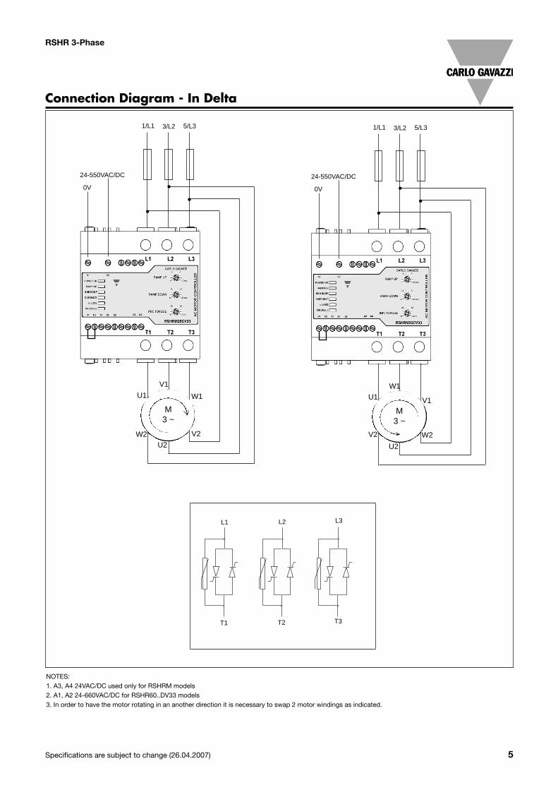
NOTES:1. A3, A4 24VAC/DC used only for RSHRM models2. A1, A2 24-660VAC/DC for RSHR60..DV32 models
Connection Diagram - In Line
3/L2 5/L31/L1
24-550VAC/DC
0V
T1
L1
T1
L1
T1
L1L1 L2 L3
T1 T2 T3
M3 ~
U1
V1
W1
Terminal Diagram
A1, A2:Control input
A3, A4: External supply
P1, P2:PTC input
11, 22: Alarms (NC)
21, 22: End Ramprelay activation (NO)
Note: A3, A4 are onlyused for theRSHRM... versions
not used A1, A2:Control input
A3, A4: External supply
P1, P2:PTC input
11, 22: Alarms (NC)
21, 22: End Ramprelay activation (NO)
Note: Applies only to RSH...V38 versions
not used

Specifications are subject to change (26.04.2007) 7
RSHR 3-Phase
Dimensions
All dimensions in mm
Operation Diagram
31
2100%
Motor voltage
Time
1 Ramp-up time 1 to 10 s. Time from zero load voltage to full load voltage.Ramp-up time 0 to 1s for RSHR...V38
NOTE: Panel mounting bracket is an accessory that has to be ordered separately
2 Ramp-down time 0 to 30 s. Time from full load voltage to zero load voltage.Ramp-down time 0 to 1s for RSHR...V38
3 Initial torque 0 to 70% voltage at the start of the ramp-up function.
1
2
3
Short circuit protectionRSHR..25.V3. RSHR..32.V3.
Type of coordination: 2Rated short circuit current 10 kA 10 kA
when protected by semiconductor fuse when protected by semiconductor fuse
Semiconductor fuse Ferraz Shawmut Ferraz Shawmutmodel, A70 QS60-4 model, A70 QS100-4

8 Specifications are subject to change (26.04.2007)
RSHR 3-Phase
IEC
NEMA
Wiring Diagram
The RSHR 3-Phase does notinclude internal bypass relays.As such semiconductors canbe damaged by short-circuitcurrents during Ramp up,Ramp Down and Running.Please note that the motorcontroller does not isolate themotor from the mains.
Figure 1: Protection of thedevice when using fuses. Protection with semiconduc-tor fuses is intended to pro-tect the motor feeder andmotor controller from damagedue to short-circuit.
Figure 2: Protection using athermal-magnetic motorprotection relay. The motor feeder is protectedbut damage to the motorcontroller is possible. Whenmotor failure occurs, if part ofthe motor winding limits thefault current and the motorfeeder is protected, this typeof protection can be consid-ered acceptable.
Figure 3: Secondary con-ductors. 3.1: Control using a 2-positionswitchWhen K is closed, the controlinput is supplied to A1, A2 andsoft starting of the motor isperformed. When K is opened,soft stopping is performed.
3.2: Motor PTC inputWhen the motor PTC sensoris connected to P1, P2 themotor controller detects over-heating of the motor wind-ings.
3.3: Auxiliary RelaysThe Alarm relay 11, 22 (NC)can be connected in serieswith the supply to the coil of amains contactor. The End ofRamp relay 21, 22 (NO) canbe used in series with thesupply to the coil of an exter-nal bypass contactor.
Figure 4: Control using ONand OFF push buttonsPushing S1 soft starts theRSHR. Pushing S2 soft stopsthe RSHR. K is an auxiliary
contact of the mains contac-tor.
Figure 5: Control using 2phasesConnecting input A1, A2 totwo of the incomming lineswill soft start the motor whenK is operated. When K isswitched off, the motor willstop (no soft stop).
Note: In the indicated wiringdiagram the RSHR is config-ured In Delta. ModelsRSHR...V32/V34/V38 shouldbe configured In Line asshown in the Connection dia-gram
RSHP
M3~
K
Fuse
Contactor
OverloadI>
RSHP
M3~
Motorprotectionrelay
A1
A2
L1 L2 L3
U/T1 V/T2 W/T3
P1
P2
MotorPTCinput
11
21
22
Alarm
Bypass ON
Common
K
M3 ~
~---
Ext.Supply
A3A4
K
KS1(ON)
S2(OFF)
A1
A2
A1
A2
L1 L2 L3
U/T1 V/T2 W/T3
K
M3 ~
Fig. 1a Fig. 2a Fig. 3a Fig. 4a Fig. 5a
RSHP
M3~
K
Fuse
Contactor
Overload
RSHP
M3~
Motorprotectionrelay
A1 A2Stop Start
K
K
A1
A2
L1 L2 L3
2T1 4T2 6T3
M3 ~
K K K
Fig. 1b Fig. 2b Fig. 4b Fig. 5b
RSHRRSHR
RSHR RSHR

Specifications are subject to change (26.04.2007) 9
RSHR 3-Phase
Operations diagram for RSHR 3-Phase
* External supply applies to RSHRM models only
10 Specifications are subject to change (26.04.2007)
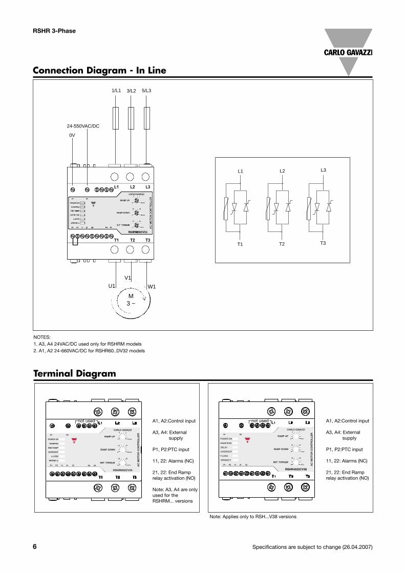
Operations diagram for RSHR 3-Phase (cont.)
Notes:Note 1: In the RSHRM models, the POWER ON Led does not give any indicationto the presence of the mains voltage at L1, L2 and L3, since it goes ON only oncethe external supply is applied.
Note 2: The number of starts per hr. and overload cycle values should always betaken in consideration when the control input is cycled.
Note 3: Over-temperature is checked before Phase loss and Phase sequencealarms. The alarms will be activated as soon as the supply is applied.
Note 4: Apart from the RSHRM models, a Phase loss on L1 or L2 will cause thedevice to reset.
Note 5: When a motor PTC is connected, electromagnetic noise may be conduct-ed into the unit. Thus if abnormal function is observed, the use of of ferrite beadson the PTC wire (at the unit end) is recommended.
Note 6: Phase loss and Phase sequence are only checked on start up. In the caseof the RSHRM, a phase loss of ALL 3 phases is detected during operation (ramp-ing and running).
Note 7: Following Ramp Down, the Delay LED remains on for 5 mins. or until themains supply is present, whichever is the shortest. The compressor will not startin case of an attempt to start during the Delay period. Once the 5 mins. haveelapsed the compressor will start as long as the control signal remains present.
Overload Cycle & Starting Duty
Overload profile
In: AC-53a: x- Tx : F-Swhere: In = nominal current through RSHR
x = overload current as a multiple of InTx = duration time for the controlled overload currents
during startingF = duty cycle (expressed as a percentage)S = no of starts/hr.
The following tables indicate the allowable no. of starts as perOverload profile: In: AC-53a: 4-4: 50-S
Table 1: RSHRxx25CV3., where xx = 22 or 40
Table 2: RSHRxx25yV3., where xx = 48, 60 or M and y = Cor D
Table 3: RSHRxx32yV3., where xx = 22, 40, 48, 60 or M andy = C or D
RSHR 3-Phase