Embed Size (px)
Citation preview

Specifications are subject to change without notice (07.03.2012) 1
Ordering Key
Motor ControllersAC Semiconductor Motor ControllerType RSXK
•Soft starting, soft stoppingof 3-phase induction motors
•Energy optimising 3-phase controlled softstarter•Adjustable integrated overload protection•Operational voltage: 230-460VAC/400-575VAC/500-690VAC 3-phase
•Operational current: 22 - 1800Arms•Keypad operation and LCD monitoring menu•Adjustable Overcurrent "shearpin" protection• Ramp-up and Ramp-down time settings up to 255sec• In Delta compatibility•Optional Modbus and Remote Keypad operation•Automatic application setup
Product DescriptionRSXK is a series of 3-phasecontrolled softstarters for 3-phase induction motors.Advanced features of theproduct include automaticapplication setup, energyoptimising capability, keypad
programming, LCD monitor-ing menu and much more.The robust design of theproduct ensures that evenapplications with starting tripclass 30 can be soft-startedand soft-stopped.
X-Line Motor ControllerKeypad operationRated operational voltageRated operational currentControl voltageHousingCooling Fans VoltageOptionsCommunications CardAuxiliary Function Card
Type SelectionType Rated operational Rated operational Control voltage
voltage Ue current Ie Uc
RSXK: X-line 40: (230-460VACrms) 0022: 22 AACrms 0382: 382AACrms B: 115 or 230VACrms *motor controller 50: (400-575VACrms) 0029: 29 AACrms 0430: 430AACrmswith Keypad 60: (500-690VACrms) 0035: 35 AACrms 0540: 540AACrmssettings 0041: 41 AACrms 0610: 610AACrms
0055: 55 AACrms 0690: 690AACrms0066: 66 AACrms 0850: 850AACrms
0080: 80 AACrms 0950: 950AACrms0097: 97 AACrms 1060: 1060AACrms0132: 132AACrms 1150: 1150AACrms0160: 160AACrms 1190: 1190AACrms0195: 195AACrms 1346: 1346AACrms0230: 230AACrms 1518: 1518AACrms0280: 280AACrms 1673: 1673AACrms
* To be supplied to terminals X1, X2 for internal control circuitry
Housing Cooling Fans Voltage* Options
0: IP00 0: No Fan selection required V00: Nil1: IP20 1: 115VACrms VC0: Communications Card
2: 230VAcrms V0F: Auxiliary Function CardVCF: Communications Card + Auxiliary Function Card
* Cooling Fans are available from RSXK..0035B1.V.. onwards.
Note: Please see Type Selection Guide on next page.
RSX K 40 0500 B 0 1V C F

Type Rated OperationalVoltage
Rated OperationalCurrent
ControlVoltage Housing Cooling Fans
Voltage Options
RSXK
40
22 - 382 B 1 0 V
00
50 C0
60 0F
CF
Type Rated OperationalVoltage
Rated OperationalCurrent
ControlVoltage Housing Cooling Fans
Voltage Options
RSXK
40
430 - 1673 B 0
1
V
00
50 C0
602
0F
CF
2 Specifications are subject to change without notice (07.03.2012)
Type Selection Guide
Selection Guide
Note: Please refer to Product Selector Guide for further information on how to select the correct softstarter.
RSXK

Specifications are subject to change without notice (07.03.2012) 3
RSXK
Output Specifications (Overload cycle according to EN/IEC 60947-4-2)
Continuous/Optimising (AC53a)
Product Code Trip Class 10B Trip Class 10 Trip Class 20 Trip Class 30
RSXK..0022… - RSXK..0160… AC53a 3.5-12:75-5 AC53a 3-23:75-5 AC53a 4-19:75-5 AC53a 4-29:75-5RSXK..0195… - RSXK..0382… AC53a 3.5-12:60-3 AC53a 3-23:60-3 AC53a 4-19:60-3 AC53a 4-29:60-3RSXK..0430… - RSXK..1673… AC53a 3.5-12:60-3 AC53a 3-23:60-3 AC53a 4-19:60-3 AC53a 4-29:60-3
General Specifications
Ramp up time 1…255 secRamp down time 0…255 secParameter Selection 6 Button KeypadForm Designation Form 1Integrated Overload Protection YesAuxiliary Contacts(programmable relays)Run (11,12,14) AC1 230VAC 3ATop of Ramp (21,22,24) AC1 230VAC 3A
Supply Specifications
Operational voltage (Ue)RSXK40…. 230 - 460VACrms (-15%+10%)RSXK50…. 400 - 575VACrms (-15%+10%)RSXK60…. 500 - 690VACrms (-15%+10%)
Rated AC frequency 50 - 60 Hz +/- 2Hz
Input Specifications
Control Supply (Us) 115V or 230VACrmsControl Supply (Uc) S0, S1 12V/24V DC or 115/230VACRated AC frequency 50/60Hz +/- 10%Rated Insulation Voltage (Ui) 690V
Externally Bypassed (AC53b)
Product Code Trip Class 10B Trip Class 10 Trip Class 20 Trip Class 30
RSXK..0022… - RSXK..0160… AC53b 3.5-12:708 AC53b 3-23:697 AC53b 4-19:701 AC53b 4-29:691RSXK..0195… - RSXK..0382… AC53b 3.5-12:1188 AC53b 3-23:1177 AC53b 4-19:1181 AC53b 4-29:1171RSXK..0430… - RSXK..1673… AC53b 3.5-12:1188 AC53b 3-23:1177 AC53b 4-19:1181 AC53b 4-29:1171

420
222
195
380
150125
400
520
340
265
500
250
4 Specifications are subject to change without notice (07.03.2012)
RSXK
Dimensions
All dimensions in mm
All dimensions in mm
Dimensions Width (W) Height (H) Depth (D) Unit Cooling Method Mounting Clearance
Side Top & Bottom FrontRSXK..0022B1.V.. To RSXK..0029B1.V.. 222 420 195 Natural Convection
RSXK..0035B1.V.. To RSXK..0160B1.V.. 222 420 195
RSXK..0195B1.V.. To RSXK..0382B1.V.. 340 520 265Forced-air with built in fan
75 2515
w olFriA
T1,T2,T3 L1,L2,L3
648
100 145 145 100
30
490
40
5015
015
015
088
100181
60
475 220285
M10M10 Earth connection point
Dimensions Width (W) Height (H) Depth (D) Unit Cooling Method Mounting ClearanceSide Top & Bottom Front
RSXK..0430B0.V.. To RSXK..0690B0.V.. 490 648 285RSXK..0541B0.V.. 508 738 282
RSXK..0850B0.V.. To RSXK..1150B0.V.. 635 746 322
RSXK..1190B0.V.. 635 782 322
RSXK..1346B0.V.. To RSXK..1673B0.V.. 775 775 475
25 200 25Forced-air with built in fan
Specifications are subject to change without notice (07.03.2012) 5
RSXK
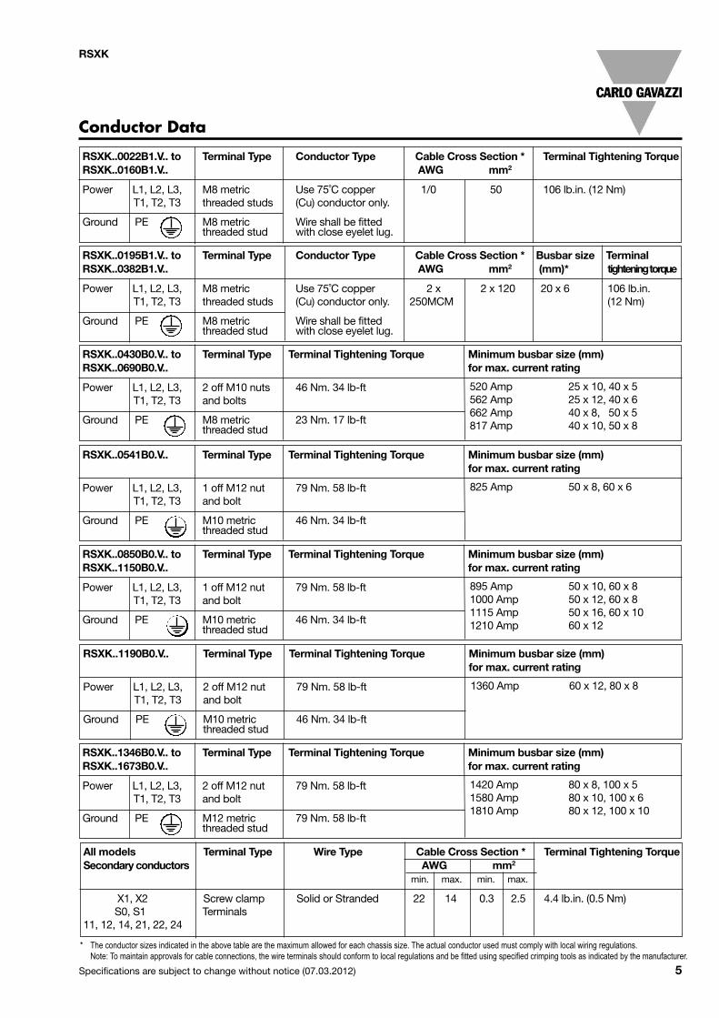
Conductor Data
* The conductor sizes indicated in the above table are the maximum allowed for each chassis size. The actual conductor used must comply with local wiring regulations.Note: To maintain approvals for cable connections, the wire terminals should conform to local regulations and be fitted using specified crimping tools as indicated by the manufacturer.
RSXK..0022B1.V.. to Terminal Type Conductor Type Cable Cross Section * Terminal Tightening TorqueRSXK..0160B1.V.. AWG mm2
Power L1, L2, L3, M8 metric Use 75˚C copper 1/0 50 106 lb.in. (12 Nm)T1, T2, T3 threaded studs (Cu) conductor only.
Ground PE M8 metric Wire shall be fittedthreaded stud with close eyelet lug.
RSXK..0430B0.V.. to Terminal Type Terminal Tightening Torque Minimum busbar size (mm)RSXK..0690B0.V.. for max. current rating
Power L1, L2, L3, 2 off M10 nuts 46 Nm. 34 lb-ftT1, T2, T3 and bolts
Ground PE M8 metric 23 Nm. 17 lb-ftthreaded stud
All models Terminal Type Wire Type Cable Cross Section * Terminal Tightening TorqueSecondary conductors AWG mm2
min. max. min. max.
X1, X2 Screw clamp Solid or Stranded 22 14 0.3 2.5 4.4 lb.in. (0.5 Nm)S0, S1 Terminals
11, 12, 14, 21, 22, 24
RSXK..0195B1.V.. to Terminal Type Conductor Type Cable Cross Section * Busbar size TerminalRSXK..0382B1.V.. AWG mm2 (mm)* tighteningtorque
Power L1, L2, L3, M8 metric Use 75˚C copper 2 x 2 x 120 20 x 6 106 lb.in.T1, T2, T3 threaded studs (Cu) conductor only. 250MCM (12 Nm)
Ground PE M8 metric Wire shall be fittedthreaded stud with close eyelet lug.
520 Amp 25 x 10, 40 x 5562 Amp 25 x 12, 40 x 6662 Amp 40 x 8, 50 x 5817 Amp 40 x 10, 50 x 8
RSXK..0541B0.V.. Terminal Type Terminal Tightening Torque Minimum busbar size (mm)for max. current rating
Power L1, L2, L3, 1 off M12 nut 79 Nm. 58 lb-ftT1, T2, T3 and bolt
Ground PE M10 metric 46 Nm. 34 lb-ftthreaded stud
825 Amp 50 x 8, 60 x 6
RSXK..0850B0.V.. to Terminal Type Terminal Tightening Torque Minimum busbar size (mm)RSXK..1150B0.V.. for max. current rating
Power L1, L2, L3, 1 off M12 nut 79 Nm. 58 lb-ftT1, T2, T3 and bolt
Ground PE M10 metric 46 Nm. 34 lb-ftthreaded stud
895 Amp 50 x 10, 60 x 81000 Amp 50 x 12, 60 x 81115 Amp 50 x 16, 60 x 101210 Amp 60 x 12
RSXK..1190B0.V.. Terminal Type Terminal Tightening Torque Minimum busbar size (mm)for max. current rating
Power L1, L2, L3, 2 off M12 nut 79 Nm. 58 lb-ftT1, T2, T3 and bolt
Ground PE M10 metric 46 Nm. 34 lb-ftthreaded stud
1360 Amp 60 x 12, 80 x 8
RSXK..1346B0.V.. to Terminal Type Terminal Tightening Torque Minimum busbar size (mm)RSXK..1673B0.V.. for max. current rating
Power L1, L2, L3, 2 off M12 nut 79 Nm. 58 lb-ftT1, T2, T3 and bolt
Ground PE M12 metric 79 Nm. 58 lb-ftthreaded stud
1420 Amp 80 x 8, 100 x 51580 Amp 80 x 10, 100 x 61810 Amp 80 x 12, 100 x 10

6 Specifications are subject to change without notice (07.03.2012)
RSXK
Note 1: The in-line configuration shown above requires thatthe firing mode be set to '0'.
Note 2: The In-Delta configuration requires that the firingmode be set to '1'. An in-line contactor controlled by theRSXK MUST be used in the In-Delta firing mode.
In Line Connection of Motors (Note 1) In Delta Connection of Motors (Note 2)
Note 3: The bypass configuration is automatically detectedas "Auto Bypass" is set as default.
Note 4: Contactor K3 is required for the ‘operation inBypass Power Circuit’ and is controlled by theprogrammable relay set as ‘Top of Ramp’ relay.
Connection for bypass operation (Note 3) Control Circuit Wiring (Note 4)
K1
Mains SupplyBusbar
L1L2L3
CircuitContactor
BypassContactor
SoftStart
L3L2L1
T3T2T1
K3
Motor Power Circuit
Wiring Diagrams

Specifications are subject to change without notice (07.03.2012) 7
RSXK
Applicable to RSXK..0022B1.V.. up to RSXK..0382B1.V..
Applicable for RSXK..0430B0.V.F up to RSXK..1673B0.V.F
Terminal Diagram
T3T2T1
L3L2L1
ElectronicControl Card
X1,X2
X1,X2
size1 size2
size1
size2
2X,1
X
AuxiliaryFunction Card
1L1
3L2
5L32
T14T2
6T3
To open cov-ers, unscrewin 4 positions
POWER TERMINALS T1, T2, T3 (Output) to inductionmotor. For correct motor rotation, these connectionsmust correspond with the supply connections at L1,L2, L3.
AUXILIARY FUNCTION CARD
To remove cover, unscrew2 positions size 14 positions size 2
EARTH STUD: Electrical ground (PE)An M8 threaded stud for connectionto the system earth.
CONTROL VOLTAGE TERMINALS X1, X2 (Input)CONTROL VOLTAGE SELECTOR SWITCHEnsure that the selector switch position corresponds to the control supply used,either 110V or 230V, before you apply the control supply.
POWER TERMINALS L1, L2, L3 (Input). Isolatable 3-phase supply (via contactor, isolator, etc.). Any phasecan connect to any terminal.
CABLE
ELECTRONIC CONTROL CARD
KEYPAD CIRCUITCARD
cover (inside view)
KEYPAD CIRCUIT CARDbehind panel
cooling fan power connection
POWER TERMINALS T1, T2, T3(Output at front) to Induction motor. Forcorrect motor rotation, these connectionsmust correspond with the supply connec-tions at L1, L2, L3
ElectronicControl Card
ELECTRONIC CONTROL CARD
CONTROL VOLTAGE TERMINALS : X1, X2 (input)CONTROL VOLTAGE SELECTOR SWITCHEnsure that the selector switch position corresponds tothe control supply used, either 115V or 230V before youapply the control supply.
EARTH STUD electrical ground (PE)An M8 orM10 threaded stud forconnection to the system earth.Position varies with chassis size.
POWER TERMINALS L1, L2, L3(Input at the back)Isolatable 3-phase
supply (via contactor, isolator or breaker).Any phase rotation.
The electronic control card is located underneaththe cover in all RSXK units. Connections shown inthe control circuit wiring diagram are made to theelectronic control card terminals as shown above.
Programmable output,Changeover contactsDefault: - Run Relay
Programmable output,Changeover contactsDefault: RampComplete
Programmable Input,Control Input 1.Default: Start/Stop
D5
J8 J9 J10
Relay
22 24 21 12 14 11 S0 S1
Micro-controller
Relay
D5 (Green) indicates the presenceof the control supply.

8 Specifications are subject to change without notice (07.03.2012)
RSXK
CE Marking LVD IEC/EN 60947-4-2
Electrostatic Discharge (ESD)
Immunity IEC/EN 61000-4-2
8kV, Air discharge
6kV, Contact
Electrical Fast Transient
Burst Immunity IEC/EN 61000-4-4
Output 2kV/5kHz
Input 2kV/5kHz
Conducted Radio Frequency IEC/EN 61000-4-6Immunity 140dbµV, 0.15-80MHz
Radio Interferencefield emission (radiated) IEC/EN 55011, Class A
Radio Interferencevoltage emission (conducted) IEC/EN 55011, Class A
Electrical Surge Immunity IEC/EN 61000-4-5
Output, line to line 1kV
Output, line to earth 2kV
Input, line to line 1kV
Input, line to earth 2kV
Radiated Radio FrequencyImmunity IEC/EN 61000-4-3
10V/m, 80 - 1000 Mhz
Standards
Alarms
Fault Code Explenation1 Phase Loss Input side phase loss at the ramp start, during ramp or during normal running.2 Too Hot The heatsink is above the maximum allowed temperature or input open circuit.
3 Comms There have been a number of serial communication errors but communications are stillactive.
4 SCR Firing Short circuit thyristor during normal running.
5 SCR Signal Short circuit thyristor during normal running or Motor side phase loss during the ramp orduring normal running.
6 SCR Signal Input side phase loss during normal running. Short circuit thyristor or motor side phaseloss during the ramp or during normal running.
7 Sensing Signal Short circuit thyristor, external noise or motor side phase loss during the ramp or duringnormal running.
8 Motor, SCR Loss Short circuit thyrisor or motor side phase loss at the start of the ramp.
9 Sensing Signal Short circuit thyristor, external noise or motor side phase loss during the ramp or duringnormal running.
10 SCR Shorted Short circuit thyristor or motor side phase loss during the ramp.
11 Low Current Current has fallen below the under-current level. (Only active during normal running)
12 C/L Time Out Current limit during the ramp has exceeded the current limit time-out period.
13 Overload Current has exceeded the overload level. (Active at all stages of operation)
14 Shearpin Current has exceeded the shearpin current level. (Only active during normal running)
15 Thermistor Thermistor input is open circuit or thermistor resistance has exceeded its trip point.
16 User A trip input from the user to the soft starter.
17 Comms Timeout Serial communications have been lost.
18 Bypass failed Bypass contactor failed to close on AC53b unit.
Stopped Cooling Displayed during the period for which the soft starter will not restart to allow heatsinkcooling.

Specifications are subject to change without notice (07.03.2012) 9
RSXK
Overload Trip Curves
0.1
1
10
100
1000
1.1 1.5 2 2.5 3 3.5 4 4.5 5 5.5 6
Class 10BClass 10
Class 20
Class 30
Trip Level Current x In
otsdnoce
SpirT
Current limit and Overload level settings are adjustable. The RSXK monitors current in one phase only and this limits overload currents in accordance with thetrip curves shown here. Parameter P106 may be changed to select Class 10B, 10, 20 or 30. This will automatically change the motor current rating (Trip level)of the unit to maintain over current protection.
Note: The overload monitors one of the phases only and the current limit level is only active during motor starting.It is recommended that the control supply is maintained between starts to ensure the integrity of the overload, which will reset on its removal.
Environmental SpecificationsAmbient temperature 0ºC to 40ºC (32ºF to 104ºF)
Above 40ºC de-rate linearly by2% of unit FLC per ºC to aderate of 40% at 60ºC.
Transport and StoragetemperatureContinuous -25ºC to +60ºC (-13ºF to 140ºF)Not exceeding 24 hrs -25ºC to +75ºC (-13ºF to 167ºF)Relative Humidity <85% non-condensing, not
exceeding 50% @ 40ºC
Degree of Protection IP20 up to RSXK..0382B1.V..IP00 - RSXK..0430B0.V.. ToRSXK..1673B0.V..
Installation altitude 1000m. Above 1000m de-ratelinearly by 1% FLC per 100mto a maximum altitude of2000m
Pollution Degree 2

10 Specifications are subject to change without notice (07.03.2012)
RSXK
Type of coordination: 1Semiconductor Fuse Types
Short CircuitCo-ordination type 1:Special purpose fuses, for the protection of semiconductor devices, rated 700VAC, can be used to obtain the requiredshort circuit ratings. Suitable for use on a circuit capable of delivering not more than the RMS Symmetrical Amperes indi-cated in this table at maximum rated operational voltage, when protected by Semiconductor Fuse type, manufactured byCompany and Mod. No. indicated. These fuses are for short circuit protection of the semiconductors and must be mountedexternally by the user between the unit and the mains supply, not between the unit and the motor.
Short Circuit Protection
Product Code Short Circuit Amp RMS (kA) SIBA Fuse Amps
RSXK..0022B1.V.. 5 2018920.80 80RSXK..0023B1.V.. 5 2018920.80 80RSXK..0029B1.V.. 5 2018920.80 80RSXK..0035B1.V.. 5 2018920.100 100RSXK..0041B1.V.. 5 2018920.100 100RSXK..0042B1.V.. 10 2061032.250 250RSXK..0055B1.V.. 10 2061032.250 250RSXK..0066B1.V.. 10 2061032.250 250RSXK..0067B1.V.. 10 2061032.250 250RSXK..0080B1.V.. 10 2061032.250 250RSXK..0081B1.V.. 10 2061032.400 400RSXK..0097B1.V.. 10 2061032.400 400RSXK..0132B1.V.. 10 2061032.400 400RSXK..0133B1.V.. 10 2061032.450 450RSXK..0160B1.V.. 18 2061032.500 500RSXK..0195B1.V.. 18 2061032.630 630RSXK..0230B1.V.. 18 2061032.630 630RSXK..0280B1.V.. 18 2061032.630 630RSXK..0350B1.V.. 18 2061032.800 800RSXK..0351B1.V.. 18 2061032.800 800RSXK..0382B1.V.. 30 2063032.900 900RSXK..0430B0.V.. 30 2063032.800 800RSXK..0540B0.V.. 30 2067132.1000 1000RSXK..0610B0.V.. 42 2067132.1000 1000RSXK..0690B0.V.. 42 2067132.1250 1250RSXK..0541B0.V.. 42 2067132.1250 1250RSXK..0850B0.V.. 85 2068132.1400 1400RSXK..0950B0.V.. 85 2068132.1400 1400RSXK..1060B0.V.. 85 2068132.1400 1400RSXK..1150B0.V.. 85 2068132.1400 1400RSXK..1190B0.V.. 85 2 x 2067132.1000 2000RSXK..1346B0.V.. 85 2 x 2067132.1250 2500RSXK..1518B0.V.. 100 2 x 2067132.2000 4000RSXK..1673B0.V.. 100 2 x 2067132.2000 4000

Specifications are subject to change without notice (07.03.2012) 11
RSXK
Accessories
• Ordering Code: MMRK• Can be used on a one to one basis, or one Keypod can
control several Soft Starters• Seven buttons with individual Start and stop• Display via a 2 line 32 character LED• Eliminates panel mounted Start and Stop push buttons,
Ammeters, Run, Top of Ramp and Alarm Lamps• The Keypod gives continous display of motor phase
current and control status, Starting, Stopping, Full Volts,Optimising, Current Limitation, Overload and FaultIndication
• Ordering Code: MMKC or Option VC.(refer to RSXK ordering code)
• Enables the set up, control and monitoring of single ormultiple RSXK softstarters
• RS485 interface with 50V isolation for demandingindustrial applications
• Interface is suitable for conection to the remote keypod ora standard Modbus network running at 9600 baud 8N1.
• Connection via standard CAT5 RJ45 terminated ethernet cable• Onboard RJ45 connector for mulitple softstarter
connection• Standard twisted pair wiring may also be used via the
secondary screw terminalsAP9A00 circuit board
Keypod
Communications Card (Modbus)
Connection of multiple RSXK softstarters via RJ45 connectors
Master Keypod
MMRK

12 Specifications are subject to change without notice (07.03.2012)
Installation Instructions (J1 - J5 Link Options)
Connection Diagram
RSXK
J1: When linked, 12V is passed through to the RJ45 connectors. This is for use with the Carlo Gavazzi net only. Itsupplies power to the remote keypod. Only the unit closest to the keypod should have this link fitted.
J2: When linked, the onboard 1k grounding resistor is shorted out. This is for use with Carlo Gavazzi net only. Only theunit closest to the keypod should have this link fitted.
J3: When linked, the serial communications isolated ground is connected to the local unit ground. If muliple MAX3157
(isolated comms) chips are connected, J3 must be shorted.
J4: When linked, a 100ohm terminating resistor is connected between the A and B RS485 lines on both the RJ45 andscrew terminal connections. For RS485 networks only, the nodes at each physical end of the network haveterminating resistors fitted.
J5: When linked, a 1k resistor is connected between screw terminal G and local ground. Normally, only one of the units
would have this link fitted.
• When connecting the remote Keypod through the RJ45 connector to a single softstarter, links J1,J2,J4 and J5should be linked.
• When connecting the softstarter to a PLC/HMI through twisted pair connection, fit terminating resistor (may beinternal) at PLC/HMI end and links J4 and J5 on the softstarter.
Connection of multiple RSXK softstarters via RJ45 connectors
Remote
Local
Switch located on side/ front of theunit when factory fitted.
Primary RJ45for connectingto a Keypod oranotherAP9A00 board
Secondary RJ45for connecting toa Keypod oranother AP9A00board
26 way pin header forconnection to 5MCadd on PCB.
Cable to single poleswitch. When closed thelocal keypad is selected.When open the remotekeypod/ RS485 networkis selected
When used with CG Keypods use RJ45 connectorswhen used with PLC/ HMI use screw terminals
Communication optionsselection links
Alternative RS485Connection for HMI or PLC
Connection to onboard keypad
FaultTransmitReceiveBoard Power On

Specifications are subject to change without notice (07.03.2012) 13
RSXK
• Ordering Code: MMFC or Option V.F(refer to RSXK ordering code)
• Two 0 - 10V Analogue Outputs• One 0 - 21V DC Input• One 4 - 20mA Input• One Thermistor Input• Two Programmable Output Relays• Two Programmable Input Relays
Auxiliary Function Card
Connection Diagram4-
20m
A0V
0-1
20V
0-2
1V
AN
2
AN
1
0V 12V
0V0V
S2 S3
41
4442
31
3432
RV1RV2
4-20mATrim
DC i/pTrim J9
K3
K4
J144232+t4-20mA
0V120V0 - 0 -
21VAN2AN10V 12V0V0V S2 00 S3 00
J10
14441343
443432 31 42 41 00 00
TerminalMarkings Function Description
0VAN1
AnalogueOutput 1
A voltage (range 0-10V) represents the analogue value of a selected parameter.(Advanced user facility)
0VAN2
AnalogueOutput 2
A voltage (range 0-10V) represents the analogue value of a selected parameter.(Advanced user facility)
0-120V No function This is an unused terminal
0-21V DC Input A 0-21V that is factory pre-set for a 0-10V input range but can be trimmed up by the userto the full 0-21V range. Can be mapped to a selected parameter. (Advanced user facility)
0V Zero volts Common 0V terminal for DC input and Voltage Output.0V12V Voltage Output A voltage source (12V, 100mAmax.) for use with either the 4-20mA input or the DC input.
(Advanced user facility)0V
4-20mA4-20mAInput
Input for an external electronic device with analogue trimming pot. Can be mapped to aselected parameter. (Advanced user facility)
ThermistorInput Two-wire input for a PTC motor thermistor. P42 indicates the relative value.
323431
ProgrammableOutputRelay K3
Relay K3 Default function - AlarmChangeover contacts that can be mapped from a selected parameter.(Advanced user facility)
424441
ProgrammableOutputRelay K4
Default function - Overload IntegratorChangeover contacts that can be mapped from a selected parameter.(Advanced user facility)
S200
ProgrammableInput 2
Control Input 2Can be mapped to a selected parameter. (Advanced user facility)
S300
ProgrammableInput 3
Control Input 3Can be mapped to a selected parameter. (Advanced user facility)
T1
T2