Embed Size (px)
Citation preview
827
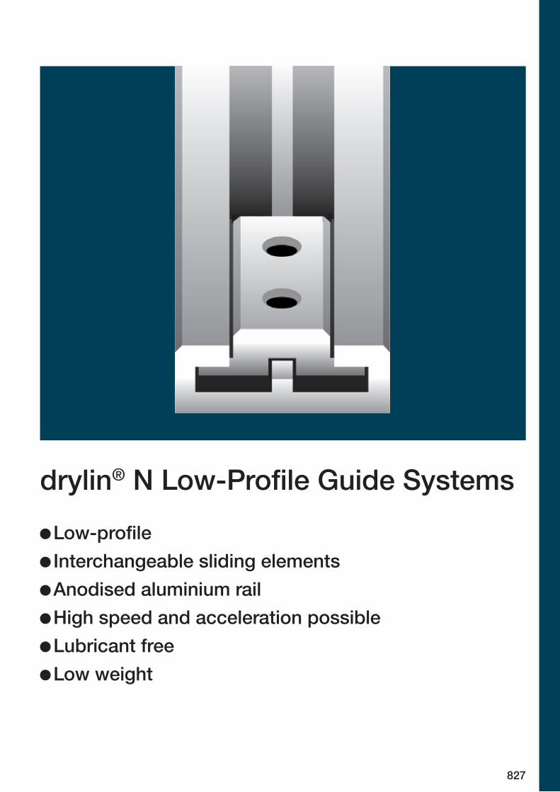
drylin® N Low-Profile Guide Systems
Low-profile Interchangeable sliding elements Anodised aluminium rail High speed and acceleration possible Lubricant free Low weight
828 8293D-CAD files, prices and delivery time www.igus.eu/drylinNLifetime calculation, configuration and more www.igus.eu/drylinN
drylin® N | Low-Profile Guide Systems | Product Overviewdrylin® N | Low-Profile Guide Systems | Advantages
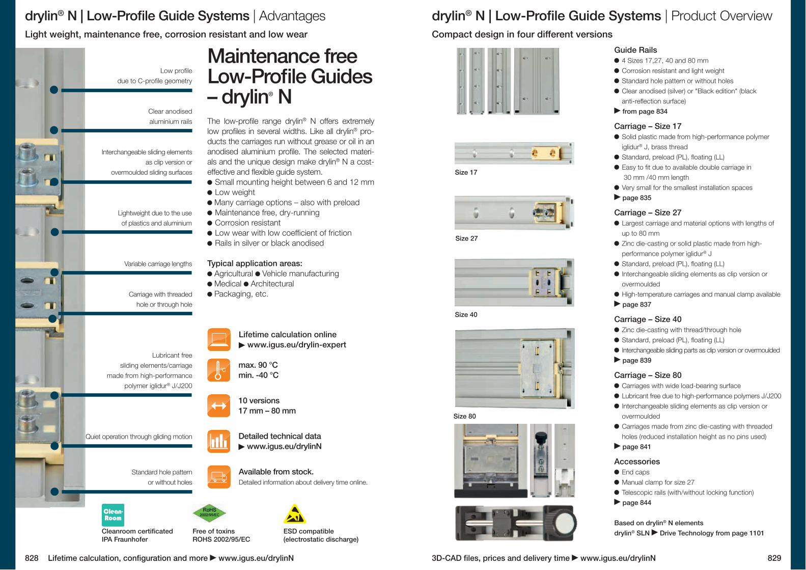
Maintenance free Low-Profile Guides – drylin® NThe low-profile range drylin® N offers extremely low profiles in several widths. Like all drylin® pro-ducts the carriages run without grease or oil in an anodised aluminium profile. The selected materi-als and the unique design make drylin® N a cost- effective and flexible guide system.
Small mounting height between 6 and 12 mm Low weight Many carriage options – also with preload Maintenance free, dry-running Corrosion resistant Low wear with low coefficient of friction Rails in silver or black anodised
Typical application areas: Agricultural Vehicle manufacturing Medical Architectural Packaging, etc.
max. 90 °C min. -40 °C
10 versions17 mm – 80 mm
Detailed technical data www.igus.eu/drylinN
Available from stock. Detailed information about delivery time online.
Lifetime calculation online www.igus.eu/drylin-expert
Lightweight due to the use of plastics and aluminium
Lubricant free sliding elements/carriage
made from high-performance polymer iglidur® J/J200
Quiet operation through gliding motion
Standard hole pattern or without holes
Carriage with threaded hole or through hole
Interchangeable sliding elements as clip version or
overmoulded sliding surfaces
Variable carriage lengths
Guide Rails 4 Sizes 17,27, 40 and 80 mm Corrosion resistant and light weight Standard hole pattern or without holes Clear anodised (silver) or "Black edition" (black anti-reflection surface) from page 834
Carriage – Size 17 Solid plastic made from high-performance polymer iglidur® J, brass thread
Standard, preload (PL), floating (LL) Easy to fit due to available double carriage in 30 mm /40 mm length
Very small for the smallest installation spaces page 835
Carriage – Size 27 Largest carriage and material options with lengths of up to 80 mm
Zinc die-casting or solid plastic made from high- performance polymer iglidur® J
Standard, preload (PL), floating (LL) Interchangeable sliding elements as clip version or overmoulded
High-temperature carriages and manual clamp available page 837
Carriage – Size 40 Zinc die-casting with thread/through hole Standard, preload (PL), floating (LL) Interchangeable sliding parts as clip version or overmoulded page 839
Carriage – Size 80 Carriages with wide load-bearing surface Lubricant free due to high-performance polymers J/J200 Interchangeable sliding elements as clip version or overmoulded
Carriages made from zinc die-casting with threaded holes (reduced installation height as no pins used) page 841
Accessories End caps Manual clamp for size 27 Telescopic rails (with/without locking function) page 844
Based on drylin® N elements drylin® SLN Drive Technology from page 1101Cleanroom certificated
IPA FraunhoferFree of toxins ROHS 2002/95/EC
ESD compatible (electrostatic discharge)
Light weight, maintenance free, corrosion resistant and low wear Compact design in four different versions
Size 17
Size 27
Size 40
Size 80
Clear anodised aluminium rails
Low profile due to C-profile geometry
830 8313D-CAD files, prices and delivery time www.igus.eu/drylinNLifetime calculation, configuration and more www.igus.eu/drylinN
drylin® N | Low-Profile Guide Systems | Application Examples drylin® N | Low-Profile Guide Systems | Online Tools
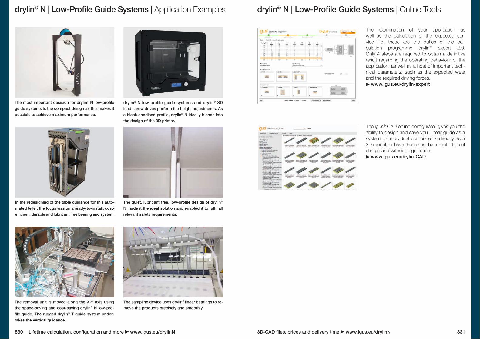
The examination of your application as well as the calculation of the expected ser-vice life, these are the duties of the cal-culation programme drylin® expert 2.0. Only 4 steps are required to obtain a definitive result regarding the operating behaviour of the application, as well as a host of important tech-nical parameters, such as the expected wear and the required driving forces.
www.igus.eu/drylin-expert
The igus® CAD online configurator gives you the ability to design and save your linear guide as a system, or individual components directly as a 3D model, or have these sent by e-mail – free of charge and without registration.
www.igus.eu/drylin-CAD
The removal unit is moved along the X-Y axis using the space-saving and cost-saving drylin® N low-pro-file guide. The rugged drylin® T guide system under-takes the vertical guidance.
The sampling device uses drylin® linear bearings to re-move the products precisely and smoothly.
The most important decision for drylin® N low-profile guide systems is the compact design as this makes it possible to achieve maximum performance.
drylin® N low-profile guide systems and drylin® SD lead screw drives perform the height adjustments. As a black anodised profile, drylin® N ideally blends into the design of the 3D printer.
In the redesigning of the table guidance for this auto-mated teller, the focus was on a ready-to-install, cost-efficient, durable and lubricant free bearing and system.
The quiet, lubricant free, low-profile design of drylin® N made it the ideal solution and enabled it to fulfil all relevant safety requirements.
M4M5M6M8M10
N17 N27 N40 N80
––– –
NW-17 NW-27 NW-40 NW-80
LLYLLZ
LLYZ
832 8333D-CAD files, prices and delivery time www.igus.eu/drylinNLifetime calculation, configuration and more www.igus.eu/drylinN
drylin® N | Low-Profile Guide Systems | Design Rules
NW-... NW-... LLZ NW-... LLY NW-... LLYZ
Floating bearings version
LLZ Floating bearing in z-directionLLY Floating bearing in y-directionLLYZ Floating bearing in yz-direction
Floating bearing
0.6 0.45 0.4 0.60.5 0.8 0.8 0.8
Y = 0.6Z = 0.5
Y = 0.3Z = 0.4
Y = 0.4Z = 0.8
Y = 0.6Z = 0.8
drylin® N | Low-Profile Guide Systems | Technical Data
Tightening torque for drylin® connections between metal parts
Note the minimal screw in depth for aluminium and zinc parts: 1.5 x Da
Metric thread Torque Recommended torque[Da] [Nm] [Nm]
1.0 - 2.8 1.52.0 - 5.5 3.04.0 - 10.0 6.08.0 - 23.0 15.022.0 - 46.0 30.0
101.00.110
100
1,000
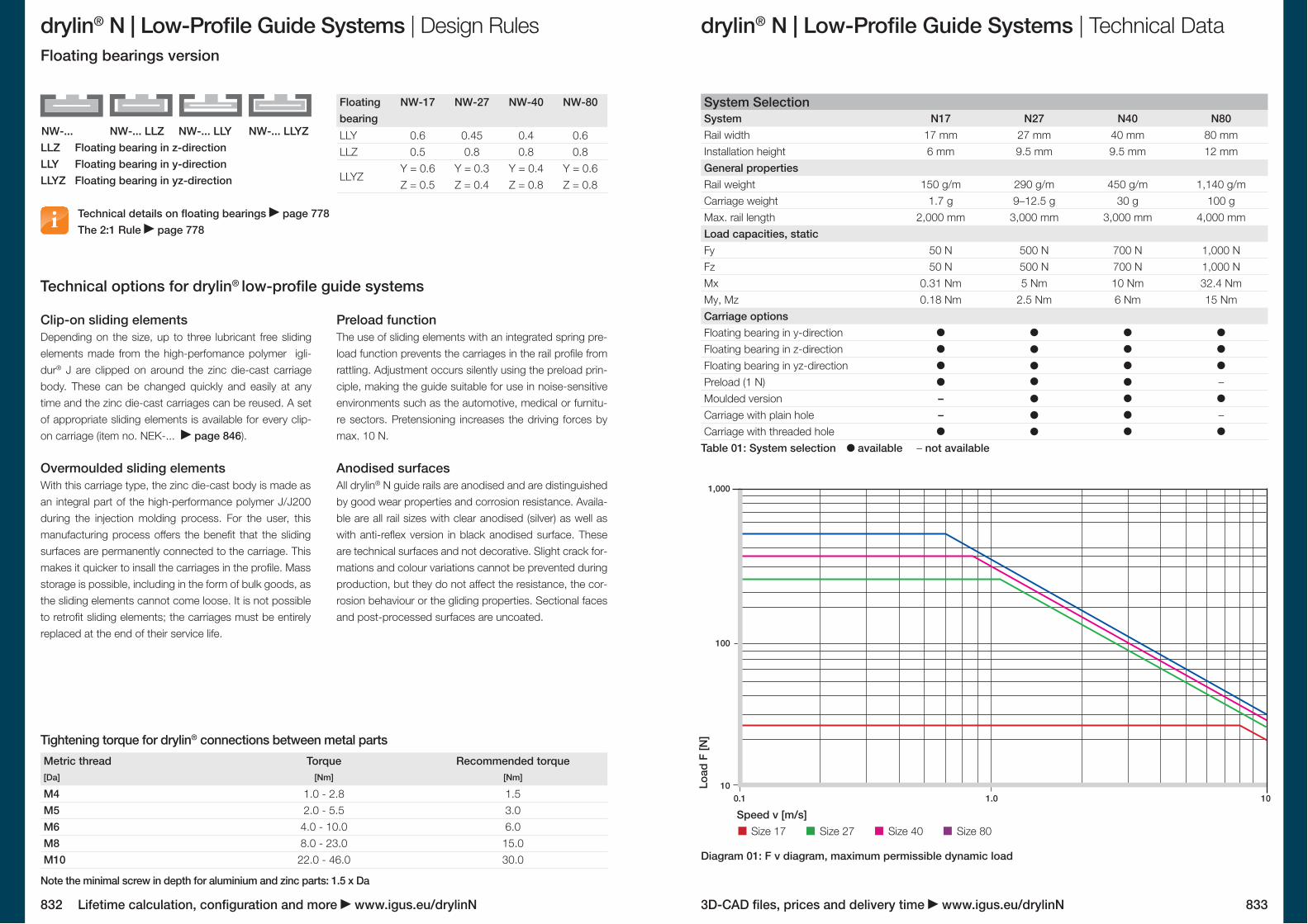
System SelectionSystemRail width 17 mm 27 mm 40 mm 80 mmInstallation height 6 mm 9.5 mm 9.5 mm 12 mmGeneral propertiesRail weight 150 g/m 290 g/m 450 g/m 1,140 g/mCarriage weight 1.7 g 9–12.5 g 30 g 100 gMax. rail length 2,000 mm 3,000 mm 3,000 mm 4,000 mmLoad capacities, staticFy 50 N 500 N 700 N 1,000 NFz 50 N 500 N 700 N 1,000 NMx 0.31 Nm 5 Nm 10 Nm 32.4 NmMy, Mz 0.18 Nm 2.5 Nm 6 Nm 15 NmCarriage optionsFloating bearing in y-directionFloating bearing in z-directionFloating bearing in yz-directionPreload (1 N)Moulded versionCarriage with plain holeCarriage with threaded hole
Table 01: System selection available – not available
Load
F [N
]
Speed v [m/s]
Diagram 01: F v diagram, maximum permissible dynamic load
Size 17 Size 27 Size 40 Size 80
Technical details on floating bearings page 778The 2:1 Rule page 778
Clip-on sliding elementsDepending on the size, up to three lubricant free sliding elements made from the high-perfomance polymer igli-dur® J are clipped on around the zinc die-cast carriage body. These can be changed quickly and easily at any time and the zinc die-cast carriages can be reused. A set of appropriate sliding elements is available for every clip-on carriage (item no. NEK-... page 846).
Overmoulded sliding elementsWith this carriage type, the zinc die-cast body is made as an integral part of the high-performance polymer J/J200 during the injection molding process. For the user, this manufacturing process offers the benefit that the sliding surfaces are permanently connected to the carriage. This makes it quicker to insall the carriages in the profile. Mass storage is possible, including in the form of bulk goods, as the sliding elements cannot come loose. It is not possible to retrofit sliding elements; the carriages must be entirely replaced at the end of their service life.
Preload functionThe use of sliding elements with an integrated spring pre-load function prevents the carriages in the rail profile from rattling. Adjustment occurs silently using the preload prin-ciple, making the guide suitable for use in noise-sensitive environments such as the automotive, medical or furnitu-re sectors. Pretensioning increases the driving forces by max. 10 N.
Anodised surfacesAll drylin® N guide rails are anodised and are distinguished by good wear properties and corrosion resistance. Availa-ble are all rail sizes with clear anodised (silver) as well as with anti-reflex version in black anodised surface. These are technical surfaces and not decorative. Slight crack for-mations and colour variations cannot be prevented during production, but they do not affect the resistance, the cor-rosion behaviour or the gliding properties. Sectional faces and post-processed surfaces are uncoated.
Technical options for drylin® low-profile guide systems
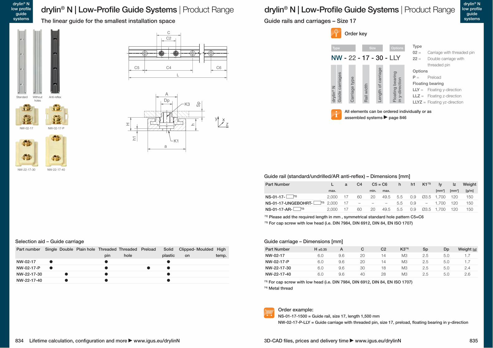
NW-02-17 • • •NW-02-17-P • • • •NW-22-17-30 • • •NW-22-17-40 • • •
NS-01-17- 72)
NS-01-17-UNGEBOHRT- 72)
NS-01-17-AR- 72)
NW-02-17NW-02-17-PNW-22-17-30NW-22-17-40
NW - 22 - 17 - 30 - LLY
NW-02-17-P
NW-22-17-40
NW-02-17
NW-22-17-30
834 835
drylin® N | Low-Profile Guide Systems | Product Range drylin® N | Low-Profile Guide Systems | Product Rangedrylin® N
low profile guide
systems
drylin® N low profile
guide systems
3D-CAD files, prices and delivery time www.igus.eu/drylinNLifetime calculation, configuration and more www.igus.eu/drylinN
Part number Single Double Plain hole Threaded pin
Threaded hole
Preload Solid plastic
Clipped-on
Moulded High temp.
Selection aid – Guide carriage
Rai
l wid
th
Car
riage
type
dryl
in® N
Gui
de c
arria
ges
OptionsSize
Leng
th o
f car
riage
Floa
ting
bear
ing
in
y-d
irect
ion
Type
Part Number L a C4 C5 = C6 h h1 K173) ly lz Weightmax. min. max. [mm4] [mm4] [g/m]
2,000 17 60 20 49.5 5.5 0.9 Ø3.5 1,700 120 1502,000 17 – – – 5.5 0.9 – 1,700 120 1502,000 17 60 20 49.5 5.5 0.9 Ø3.5 1,700 120 150
Guide carriage – Dimensions [mm]
73) For cap screw with low head (i.e. DIN 7984, DIN 6912, DIN 84, EN ISO 1707)74) Metal thread
Guide rail (standard/undrilled/AR anti-reflex) – Dimensions [mm]
72) Please add the required length in mm , symmetrical standard hole pattern C5=C673) For cap screw with low head (i.e. DIN 7984, DIN 6912, DIN 84, EN ISO 1707)
Part Number H ±0.35 A C C2 K374) Sp Dp Weight [g]
6.0 9.6 20 14 M3 2.5 5.0 1.76.0 9.6 20 14 M3 2.5 5.0 1.76.0 9.6 30 18 M3 2.5 5.0 2.46.0 9.6 40 28 M3 2.5 5.0 2.6
The linear guide for the smallest installation space Guide rails and carriages – Size 17
Order example:NS-01-17-1500 = Guide rail, size 17, length 1,500 mm NW-02-17-P-LLY = Guide carriage with threaded pin, size 17, preload, floating bearing in y-direction
Order key
Type02 = Carriage with threaded pin22 = Double carriage with
threaded pinOptionsP = PreloadFloating bearingLLY = Floating y-direction LLZ = Floating z-direction LLYZ = Floating yz-direction
Standard Without holes
Anti-reflex
All elements can be ordered individually or as assembled systems page 846
C2C
C4C5 C6L
a
Hh1 K1
h
A
K3Dp
Sp
zy x
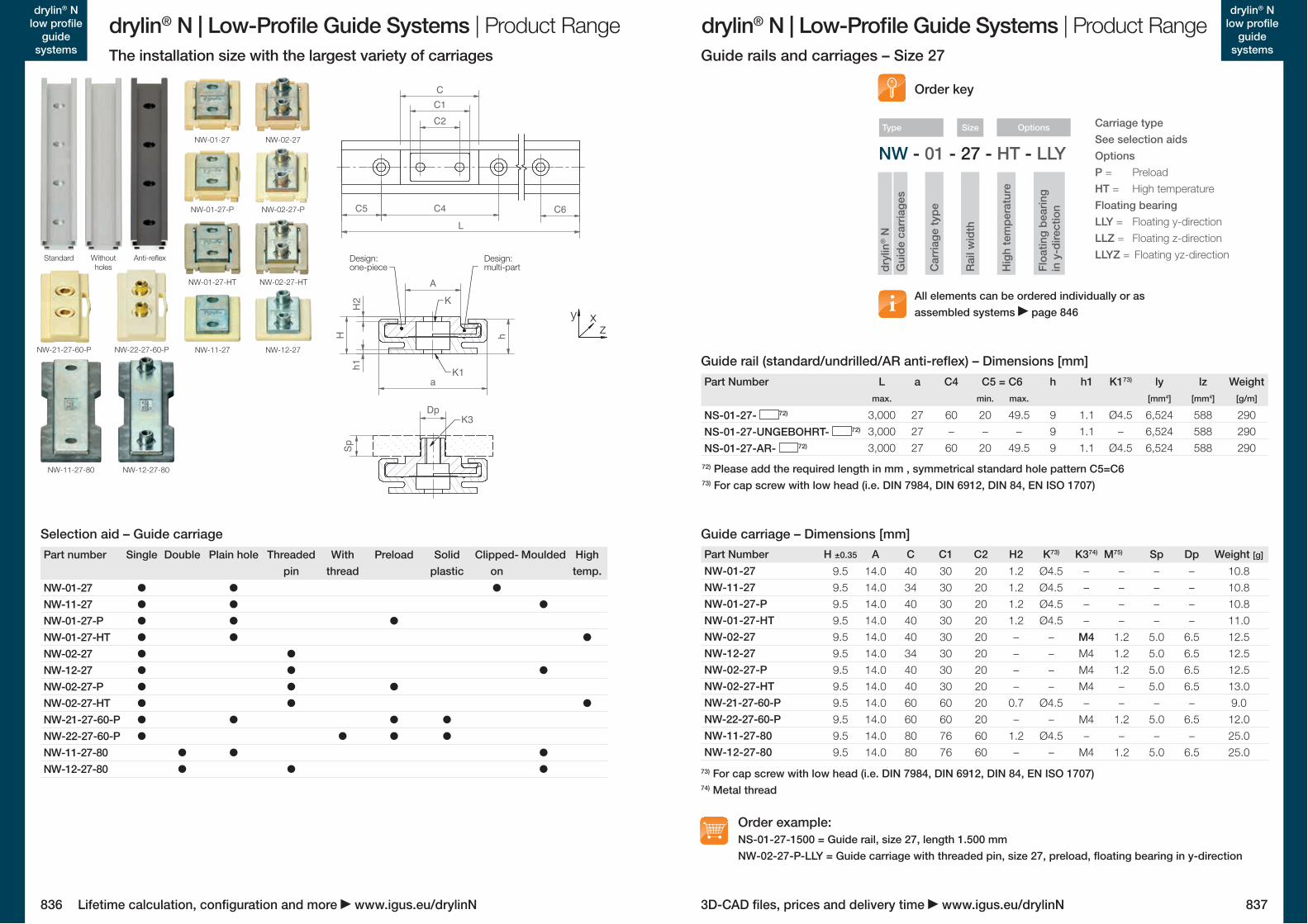
NW-01-27 • • •NW-11-27 • • •NW-01-27-P • • •NW-01-27-HT • • •NW-02-27 • •NW-12-27 • • •NW-02-27-P • • •NW-02-27-HT • • •NW-21-27-60-P • • • •NW-22-27-60-P • • • •NW-11-27-80 • • •NW-12-27-80 • • •
NW-01-27NW-11-27NW-01-27-PNW-01-27-HTNW-02-27NW-12-27NW-02-27-PNW-02-27-HTNW-21-27-60-PNW-22-27-60-PNW-11-27-80NW-12-27-80
NW - 01 - 27 - HT - LLY
NS-01-27- 72)
NS-01-27-UNGEBOHRT- 72)
NS-01-27-AR- 72)
NW-11-27NW-21-27-60-P
NW-11-27-80
NW-12-27NW-22-27-60-P
NW-12-27-80
NW-02-27-HT
NW-02-27-P
NW-02-27
NW-01-27-HT
NW-01-27-P
NW-01-27
836 837
drylin® N | Low-Profile Guide Systems | Product Range drylin® N | Low-Profile Guide Systems | Product Rangedrylin® N
low profile guide
systems
drylin® N low profile
guide systems
3D-CAD files, prices and delivery time www.igus.eu/drylinNLifetime calculation, configuration and more www.igus.eu/drylinN
Part number Single Double Plain hole Threaded pin
With thread
Preload Solid plastic
Clipped-on
Moulded High temp.
Part Number H ±0.35 A C C1 C2 H2 K73) K374) M75) Sp Dp Weight [g]
9.5 14.0 40 30 20 1.2 Ø4.5 – – – – 10.89.5 14.0 34 30 20 1.2 Ø4.5 – – – – 10.89.5 14.0 40 30 20 1.2 Ø4.5 – – – – 10.89.5 14.0 40 30 20 1.2 Ø4.5 – – – – 11.09.5 14.0 40 30 20 – – M4 1.2 5.0 6.5 12.59.5 14.0 34 30 20 – – M4 1.2 5.0 6.5 12.59.5 14.0 40 30 20 – – M4 1.2 5.0 6.5 12.59.5 14.0 40 30 20 – – M4 – 5.0 6.5 13.09.5 14.0 60 60 20 0.7 Ø4.5 – – – – 9.09.5 14.0 60 60 20 – – M4 1.2 5.0 6.5 12.09.5 14.0 80 76 60 1.2 Ø4.5 – – – – 25.09.5 14.0 80 76 60 – – M4 1.2 5.0 6.5 25.0
Guide carriage – Dimensions [mm]Selection aid – Guide carriage
73) For cap screw with low head (i.e. DIN 7984, DIN 6912, DIN 84, EN ISO 1707)74) Metal thread
The installation size with the largest variety of carriages Guide rails and carriages – Size 27
Car
riage
type
dryl
in® N
Gui
de c
arria
ges
Options
Hig
h te
mpe
ratu
re
Floa
ting
bear
ing
in
y-d
irect
ion
Type
All elements can be ordered individually or as assembled systems page 846
Order key
Carriage typeSee selection aidsOptionsP = PreloadHT = High temperatureFloating bearingLLY = Floating y-direction LLZ = Floating z-direction LLYZ = Floating yz-direction
Guide rail (standard/undrilled/AR anti-reflex) – Dimensions [mm]
Order example:NS-01-27-1500 = Guide rail, size 27, length 1.500 mm NW-02-27-P-LLY = Guide carriage with threaded pin, size 27, preload, floating bearing in y-direction
Standard Without holes
Anti-reflex
Part Number L a C4 C5 = C6 h h1 K173) ly lz Weightmax. min. max. [mm4] [mm4] [g/m]
3,000 27 60 20 49.5 9 1.1 Ø4.5 6,524 588 2903,000 27 – – – 9 1.1 – 6,524 588 2903,000 27 60 20 49.5 9 1.1 Ø4.5 6,524 588 290
72) Please add the required length in mm , symmetrical standard hole pattern C5=C673) For cap screw with low head (i.e. DIN 7984, DIN 6912, DIN 84, EN ISO 1707)
H2H
h1
h
AK
K1
Sp
a
Design: one-piece
Design: multi-part
Sp
DpK3
C2C1C
C4C5 C6L
C2
zy x
Size
Rai
l wid
th
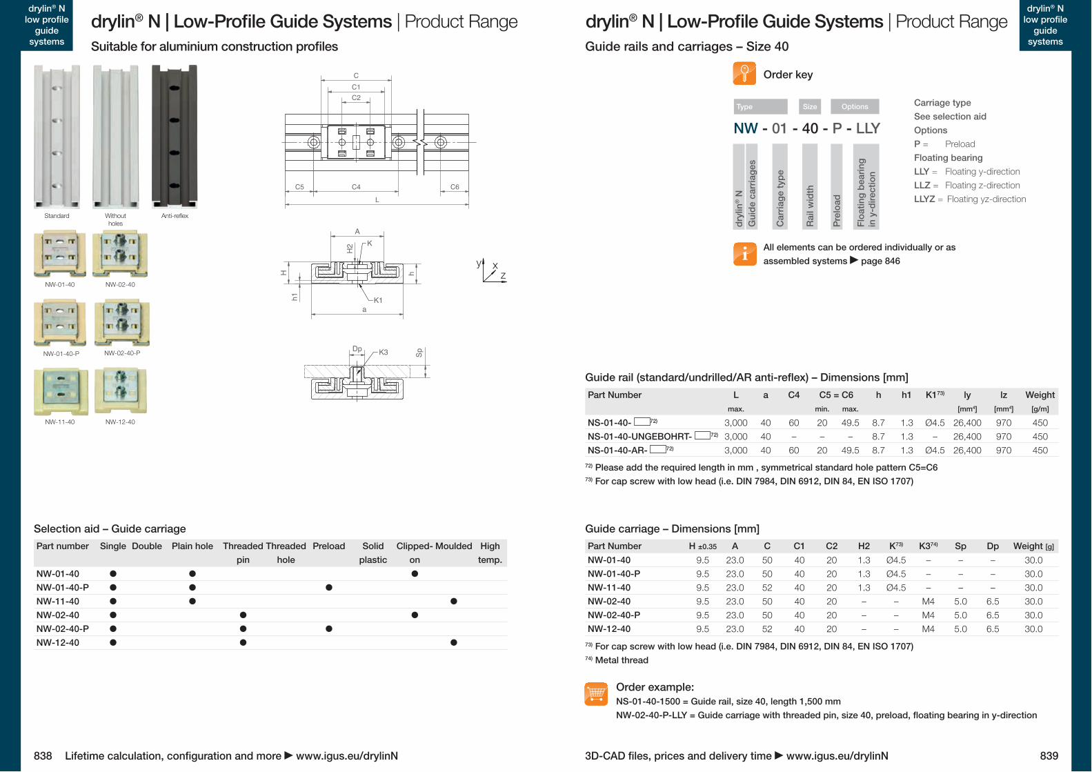
NW - 01 - 40 - P - LLY
NW-01-40NW-01-40-PNW-11-40NW-02-40NW-02-40-PNW-12-40
NW-01-40 • • •NW-01-40-P • • •NW-11-40 • • •NW-02-40 • • •NW-02-40-P • • •NW-12-40 • • •
NS-01-40- 72)
NS-01-40-UNGEBOHRT- 72)
NS-01-40-AR- 72)
NW-01-40
NW-11-40
NW-01-40-P
NW-12-40
NW-02-40
NW-02-40-P
838 839
drylin® N | Low-Profile Guide Systems | Product Range drylin® N | Low-Profile Guide Systems | Product Rangedrylin® N
low profile guide
systems
drylin® N low profile
guide systems
3D-CAD files, prices and delivery time www.igus.eu/drylinNLifetime calculation, configuration and more www.igus.eu/drylinN
zy x
Guide carriage – Dimensions [mm]
73) For cap screw with low head (i.e. DIN 7984, DIN 6912, DIN 84, EN ISO 1707)74) Metal thread
Guide rail (standard/undrilled/AR anti-reflex) – Dimensions [mm]
Suitable for aluminium construction profiles Guide rails and carriages – Size 40
Rai
l wid
th
Pre
load
Car
riage
type
dryl
in® N
Gui
de c
arria
ges
OptionsSize
Floa
ting
bear
ing
in
y-d
irect
ion
Type
All elements can be ordered individually or as assembled systems page 846
Order key
Carriage typeSee selection aidOptionsP = PreloadFloating bearingLLY = Floating y-direction LLZ = Floating z-direction LLYZ = Floating yz-direction
Part Number H ±0.35 A C C1 C2 H2 K73) K374) Sp Dp Weight [g]
9.5 23.0 50 40 20 1.3 Ø4.5 – – – 30.09.5 23.0 50 40 20 1.3 Ø4.5 – – – 30.09.5 23.0 52 40 20 1.3 Ø4.5 – – – 30.09.5 23.0 50 40 20 – – M4 5.0 6.5 30.09.5 23.0 50 40 20 – – M4 5.0 6.5 30.09.5 23.0 52 40 20 – – M4 5.0 6.5 30.0
Order example:NS-01-40-1500 = Guide rail, size 40, length 1,500 mm NW-02-40-P-LLY = Guide carriage with threaded pin, size 40, preload, floating bearing in y-direction
Part number Single Double Plain hole Threaded pin
Threaded hole
Preload Solid plastic
Clipped-on
Moulded High temp.
Selection aid – Guide carriage
Standard Without holes
Anti-reflex
Part Number L a C4 C5 = C6 h h1 K173) ly lz Weightmax. min. max. [mm4] [mm4] [g/m]
3,000 40 60 20 49.5 8.7 1.3 Ø4.5 26,400 970 4503,000 40 – – – 8.7 1.3 – 26,400 970 4503,000 40 60 20 49.5 8.7 1.3 Ø4.5 26,400 970 450
72) Please add the required length in mm , symmetrical standard hole pattern C5=C673) For cap screw with low head (i.e. DIN 7984, DIN 6912, DIN 84, EN ISO 1707)
C2C1C
C5 C4 C6L
Dp SpK3H2
A
H
a
h1
h
K
K1
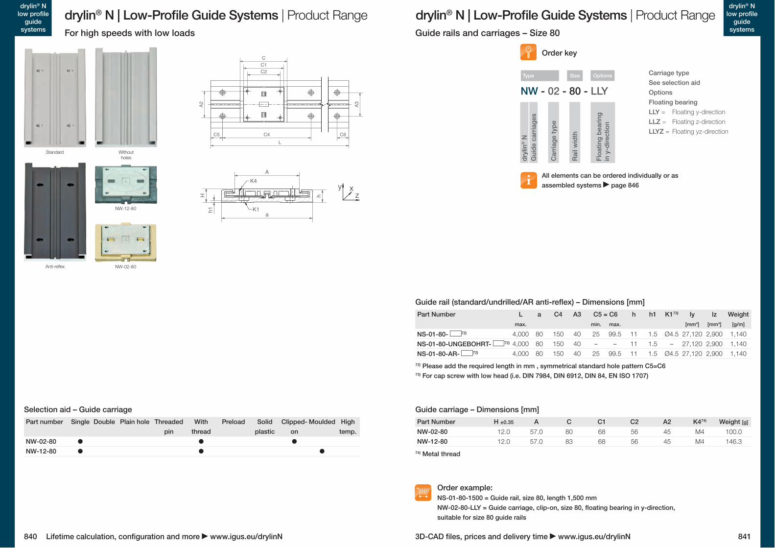
NW-02-80NW-12-80NW-02-80 • • •
NW-12-80 • • •
NW - 02 - 80 - LLY
NS-01-80- 72)
NS-01-80-UNGEBOHRT- 72)
NS-01-80-AR- 72)
NW-02-80
NW-12-80
840 841
drylin® N | Low-Profile Guide Systems | Product Range drylin® N | Low-Profile Guide Systems | Product Rangedrylin® N
low profile guide
systems
drylin® N low profile
guide systems
3D-CAD files, prices and delivery time www.igus.eu/drylinNLifetime calculation, configuration and more www.igus.eu/drylinN
Part Number H ±0.35 A C C1 C2 A2 K474) Weight [g]
12.0 57.0 80 68 56 45 M4 100.012.0 57.0 83 68 56 45 M4 146.3
Guide carriage – Dimensions [mm]
74) Metal thread
For high speeds with low loads Guide rails and carriages – Size 80
All elements can be ordered individually or as assembled systems page 846
Order key
Carriage typeSee selection aidOptionsFloating bearingLLY = Floating y-direction LLZ = Floating z-direction LLYZ = Floating yz-direction
Order example:NS-01-80-1500 = Guide rail, size 80, length 1,500 mm NW-02-80-LLY = Guide carriage, clip-on, size 80, floating bearing in y-direction, suitable for size 80 guide rails
Car
riage
type
dryl
in® N
Gui
de c
arria
ges
Options
Floa
ting
bear
ing
in
y-d
irect
ion
Type
Part number Single Double Plain hole Threaded pin
With thread
Preload Solid plastic
Clipped-on
Moulded High temp.
Selection aid – Guide carriage
Guide rail (standard/undrilled/AR anti-reflex) – Dimensions [mm]
72) Please add the required length in mm , symmetrical standard hole pattern C5=C673) For cap screw with low head (i.e. DIN 7984, DIN 6912, DIN 84, EN ISO 1707)
Standard Without holes
Anti-reflex
Part Number L a C4 A3 C5 = C6 h h1 K173) ly lz Weightmax. min. max. [mm4] [mm4] [g/m]
4,000 80 150 40 25 99.5 11 1.5 Ø4.5 27,120 2,900 1,1404,000 80 150 40 – – 11 1.5 – 27,120 2,900 1,1404,000 80 150 40 25 99.5 11 1.5 Ø4.5 27,120 2,900 1,140
C5 C4 C6L
A2 A3
C2C1C
AK4
K1
h
ah1H z
y x
Rai
l wid
th
Size
N T - LM - 35 - 300
N T - 35 - 300 - 320
N T - 35 - 300
N T - 35 - 300 - 200
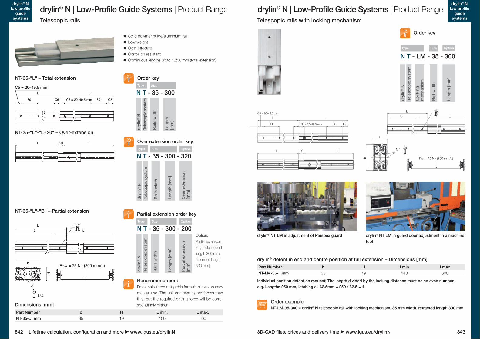
NT-35-… mm
NT-LM-35-...mm
842 843
drylin® N | Low-Profile Guide Systems | Product Range drylin® N | Low-Profile Guide Systems | Product Rangedrylin® N
low profile guide
systems
drylin® N low profile
guide systems
3D-CAD files, prices and delivery time www.igus.eu/drylinNLifetime calculation, configuration and more www.igus.eu/drylinN
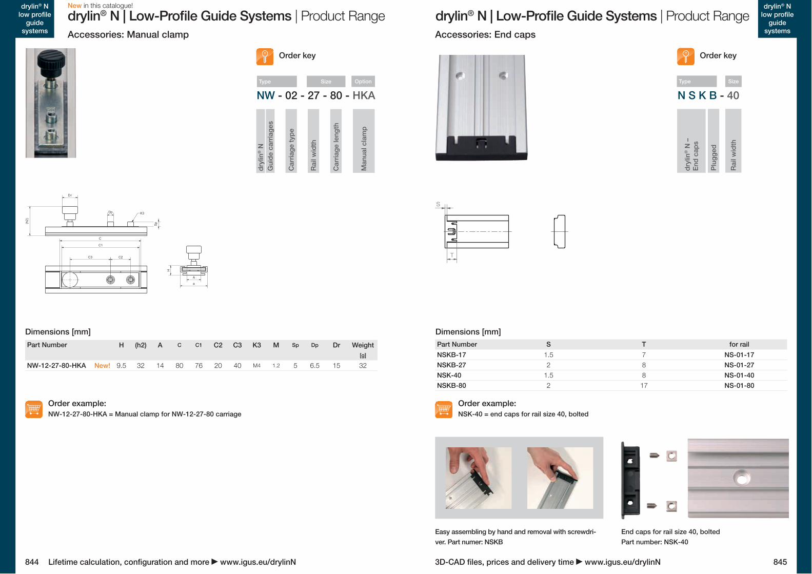
Telescopic rails with locking mechanismTelescopic rails
Order example:NT-LM-35-300 = drylin® N telescopic rail with locking mechanism, 35 mm width, retracted length 300 mm
Part Number b H Lmin Lmax35 19 140 600
drylin® NT LM in adjustment of Perspex guard drylin® NT LM in guard door adjustment in a machine tool
drylin® detent in end and centre position at full extension – Dimensions [mm]
Individual position detent on request; The length divided by the locking distance must be an even number. e.g. Lengths 250 mm, latching all 62.5mm = 250 / 62.5 = 4
M4
H
b
LBL
LL 20
Fmax = 75 N · (200 mm/L)
LL
60 C6 60 C5 = 20–49.5 mm
C5 = 20–49.5 mm
M4
H
b
LBL
LL 20
Fmax = 75 N · (200 mm/L)
LL
60 C6 60 C5 = 20–49.5 mm
C5 = 20–49.5 mm
M4
H
b
LBL
LL 20
Fmax = 75 N · (200 mm/L)
LL
60 C6 60 C5 = 20–49.5 mm
C5 = 20–49.5 mm
M4
H
b
LBL
LL 20
Fmax = 75 N · (200 mm/L)
LL
60 C6 60 C5 = 20–49.5 mm
C5 = 20–49.5 mm
Order key
Rai
l wid
th
Lock
ing
mec
hani
sm
dryl
in® N
Tele
scop
ic s
yste
m
OptionSize
Leng
th [m
m]
Type
C5 = 20–49.5 mm L L
60 C6 C6 = 20–49.5 mm 60 C5
L 20 L
L
Part Number b H L min. L max.35 19 100 600
Order keyNT-35-"L" – Total extension
Solid polymer guide/aluminium rail Low weight Cost-effective Corrosion resistant Continuous lengths up to 1,200 mm (total extension)
Dimensions [mm]
Over extension order key
Option:Partial extension (e.g.: telescoped length 300 mm, extended length 500 mm)
Partial extension order key
NT-35-"L"-"L+20" – Over-extension
NT-35-"L"-"B" – Partial extension
Recommendation:Fmax calculated using this formula allows an easy manual use. The unit can take higher forces than this, but the required driving force will be corre-spondingly higher.
Fmax = 75 N · (200 mm/L)b
H
M4
B L
Leng
th [m
m]
Leng
th [m
m]
Leng
th
[mm
]
Rai
ls w
idth
Rai
ls w
idth
Rai
ls w
idth
dryl
in® N
dryl
in® N
dryl
in® N
Tele
scop
ic s
yste
mTe
lesc
opic
sys
tem
Tele
scop
ic s
yste
mOption
Option
Par
tial e
xten
sion
[m
m]
Ove
r ext
ensi
on
[mm
]
Type
Type
Type
Size
Size
Size
N S K B - 40NW - 02 - 27 - 80 - HKA
NSKB-17NSKB-27NSK-40NSKB-80
NW-12-27-80-HKA
844 845
drylin® N | Low-Profile Guide Systems | Product Range drylin® N | Low-Profile Guide Systems | Product Rangedrylin® N
low profile guide
systems
drylin® N low profile
guide systems
3D-CAD files, prices and delivery time www.igus.eu/drylinNLifetime calculation, configuration and more www.igus.eu/drylinN
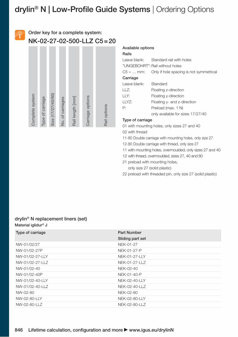
Accessories: End capsAccessories: Manual clamp
Order example:NSK-40 = end caps for rail size 40, bolted
Order example:NW-12-27-80-HKA = Manual clamp for NW-12-27-80 carriage
S
T
Part Number S T for rail1.5 7 NS-01-172 8 NS-01-27
1.5 8 NS-01-402 17 NS-01-80
Dimensions [mm]
Easy assembling by hand and removal with screwdri-ver. Part numer: NSKB
End caps for rail size 40, bolted Part number: NSK-40
Order key
Rai
l wid
th
Plu
gged
dryl
in® N
–
End
caps
SizeType
C2
K3
(h2)
r
C
C3
Dp
C1
Sp
D
a
H
A
Part Number H (h2) A C C1 C2 C3 K3 M Sp Dp Dr Weight[g]
New! 9.5 32 14 80 76 20 40 M4 1.2 5 6.5 15 32
Dimensions [mm]
Rai
l wid
th
Car
riage
type
dryl
in® N
Gui
de c
arria
ges
OptionSize
Car
riage
leng
th
Man
ual c
lam
p
Type
Order key
New in this catalogue!
NW-01/02/27 NEK-01-27NW-01/02-27P NEK-01-27-PNW-01/02-27-LLY NEK-01-27-LLYNW-01/02-27-LLZ NEK-01-27-LLZNW-01/02-40 NEK-02-40NW-01/02-40P NEK-01-40-PNW-01/02-40-LLY NEK-02-40-LLYNW-01/02-40-LLZ NEK-02-40-LLZNW-02-80 NEK-02-80NW-02-80-LLY NEK-02-80-LLYNW-02-80-LLZ NEK-02-80-LLZ
NK-02-27-02-500-LLZ C5 = 20
846 Lifetime calculation, configuration and more www.igus.eu/drylinN
drylin® N | Low-Profile Guide Systems | Ordering Options
drylin® N replacement liners (set)Material iglidur® J
Available optionsRailsLeave blank: Standard rail with holes"UNGEBOHRT": Rail without holesC5 = … mm: Only if hole spacing is not symmetrical CarriageLeave blank: StandardLLZ: Floating z-directionLLY: Floating y-directionLLYZ: Floating y- and z-directionP: Preload (max. 1 N)
only available for sizes 17/27/40Type of carriage01 with mounting holes, only sizes 27 and 4002 with thread11-80 Double carriage with mounting holes, only size 27 12-80 Double carriage with thread, only size 2711 with mounting holes, overmoulded, only sizes 27 and 4012 with thread, overmoulded, sizes 27, 40 and 8021 preload with mounting holes,
only size 27 (solid plastic)22 preload with threaded pin, only size 27 (solid plastic)
Type of carriage Part NumberSliding part set
Order key for a complete system:C
ompl
ete
syst
em
Type
of c
arria
ge
Siz
e (1
7/27
/40/
80)
No.
of c
arria
ges
Rai
l len
gth
[mm
]
Car
riage
opt
ions
Rai
l opt
ions