Embed Size (px)
Citation preview
igus® (UK) Ltd | Phone (01604) 677240 Fax -245 | [email protected] | www.igus.co.uk
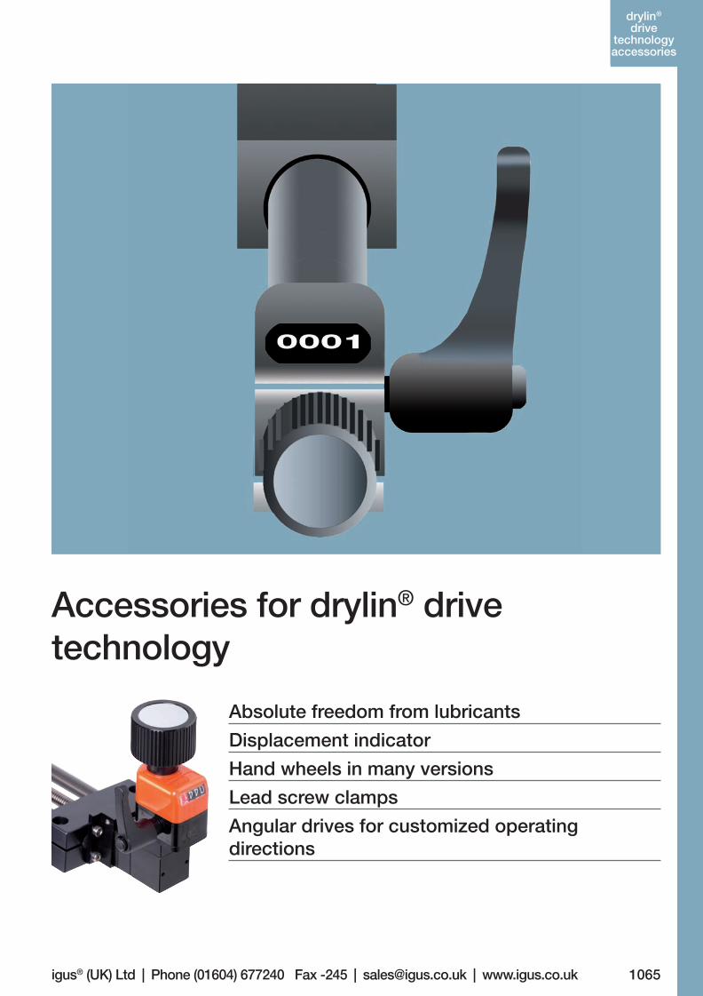
Accessories for drylin® drive technology
Absolute freedom from lubricants
Displacement indicator
Hand wheels in many versions
Lead screw clamps
Angular drives for customized operating directions
1065
drylin®
drivetechnology
Lifetime calculation, CAD fi les and much more support www.igus.co.uk/en/drylinSET
drylin®
drive technology accessories
06_GL6_UK_drylin_Antrieb.indd 59 26.02.13 10:48
1066 More information www.igus.co.uk/en/drylin-accessories
drylin®
drive technology accessories drylin® Drive Technology | Accessories
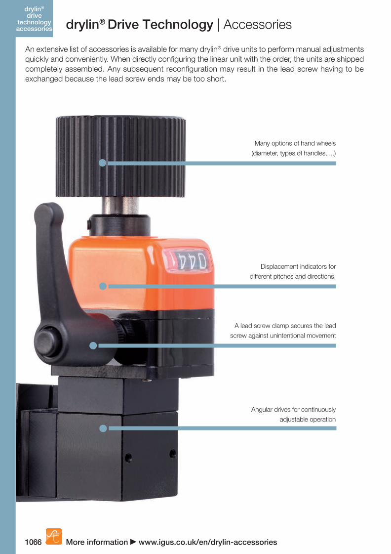
An extensive list of accessories is available for many drylin® drive units to perform manual adjustments quickly and conveniently. When directly configuring the linear unit with the order, the units are shipped completely assembled. Any subsequent reconfiguration may result in the lead screw having to be exchanged because the lead screw ends may be too short.
Many options of hand wheels
(diameter, types of handles, ...)
Displacement indicators for
different pitches and directions.
A lead screw clamp secures the lead
screw against unintentional movement
Angular drives for continuously
adjustable operation
06_GL6_UK_drylin_Antrieb.indd 60 26.02.13 10:48
1067igus® (UK) Ltd | Phone (01604) 677240 Fax -245 | [email protected] | www.igus.co.uk
drylin®
drive technology accessories
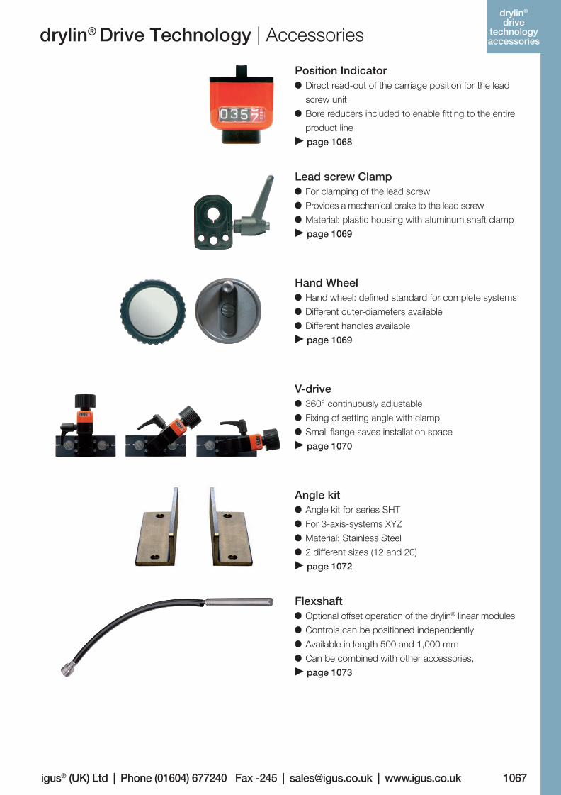
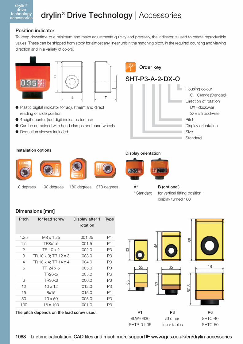
Position Indicator Direct read-out of the carriage position for the lead
screw unit
Bore reducers included to enable fi tting to the entire
product line
page 1068
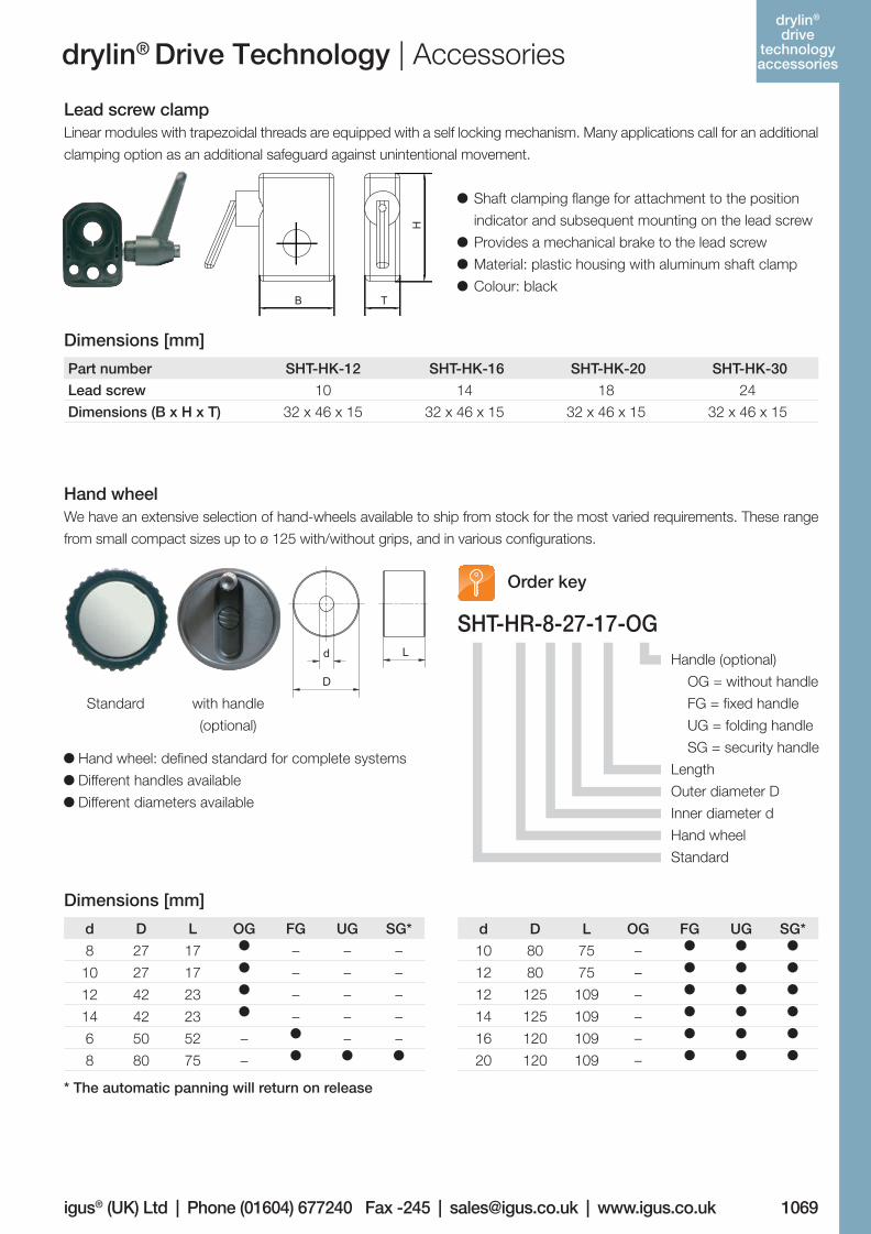
Lead screw Clamp For clamping of the lead screw
Provides a mechanical brake to the lead screw
Material: plastic housing with aluminum shaft clamp
page 1069
Hand Wheel Hand wheel: defi ned standard for complete systems
Different outer-diameters available
Different handles available
page 1069
V-drive 360° continuously adjustable
Fixing of setting angle with clamp
Small fl ange saves installation space
page 1070
Angle kit Angle kit for series SHT
For 3-axis-systems XYZ
Material: Stainless Steel
2 different sizes (12 and 20)
page 1072
Flexshaft Optional offset operation of the drylin® linear modules
Controls can be positioned independently
Available in length 500 and 1,000 mm
Can be combined with other accessories,
page 1073
drylin® Drive Technology | Accessories
06_GL6_UK_drylin_Antrieb.indd 61 26.02.13 10:48
1068 Lifetime calculation, CAD files and much more support www.igus.co.uk/en/drylin-accessories
drylin®
drive technology accessories drylin® Drive Technology | Accessories
SHT-P3-A-2-DX-O
Plastic digital indicator for adjustment and direct
reading of slide position
4-digit counter (red digit indicates tenths))
Can be combined with hand clamps and hand wheels
Reduction sleeves included
22 32 48
33
46
66
26 33
50,5
P1
SLW-0630
SHTP-01-06
P6
SHTC-40
SHTC-50
P3
all other
linear tables
Order key
Housing colour
O = Orange (Standard)
Direction of rotation
DX =clockwise
SX = anti clockwise
Pitch
Display orientation
Size
Standard
Installation optionsDisplay orientation
0 degrees 90 degrees 180 degrees 270 degrees A* B (optional)
* Standard for vertical fitting position:
display turned 180
Dimensions [mm]
The pitch depends on the lead screw used.
Position indicatorTo keep downtime to a minimum and make adjustments quickly and precisely, the indicator is used to create reproducible
values. These can be shipped from stock for almost any linear unit in the matching pitch, in the required counting and viewing
direction and in a variety of colors.
Pitch for lead screw Display after 1
rotation
Type
1,25 M8 x 1.25 001.25 P1
1,5 TR8x1.5 001.5 P1
2 TR 10 x 2 002.0 P3
3 TR 10 x 3; TR 12 x 3 003.0 P3
4 TR 18 x 4; TR 14 x 4 004.0 P3
5 TR 24 x 5
TR26x5
005.0
005.0
P3
P6
6 TR30x6 006.0 P6
12 10 x 12 012.0 P3
15 8x15 015.0 P1
50 10 x 50 005.0 P3
100 18 x 100 001.0 P3
06_GL6_UK_drylin_Antrieb.indd 62 26.02.13 10:48
1069igus® (UK) Ltd | Phone (01604) 677240 Fax -245 | [email protected] | www.igus.co.ukLifetime calculation, CAD files and much more support www.igus.co.uk/en/drylin-accessories
drylin®
drive technology accessoriesdrylin® Drive Technology | Accessories
SHT-HR-8-27-17-OG
d D L OG FG UG SG*
8 27 17 – – –
10 27 17 – – –
12 42 23 – – –
14 42 23 – – –
6 50 52 – – –
8 80 75 –
Part number SHT-HK-12 SHT-HK-16 SHT-HK-20 SHT-HK-30
Lead screw 10 14 18 24
Dimensions (B x H x T) 32 x 46 x 15 32 x 46 x 15 32 x 46 x 15 32 x 46 x 15
Dimensions [mm]
Hand wheelWe have an extensive selection of hand-wheels available to ship from stock for the most varied requirements. These range
from small compact sizes up to ø 125 with/without grips, and in various configurations.
Lead screw clampLinear modules with trapezoidal threads are equipped with a self locking mechanism. Many applications call for an additional
clamping option as an additional safeguard against unintentional movement.
Hand wheel: defined standard for complete systems
Different handles available
Different diameters available
Shaft clamping flange for attachment to the position
indicator and subsequent mounting on the lead screw
Provides a mechanical brake to the lead screw
Material: plastic housing with aluminum shaft clamp
Colour: black
Dimensions [mm]
Standard with handle
(optional)
* The automatic panning will return on release
Order key
Handle (optional)
OG = without handle
FG = fixed handle
UG = folding handle
SG = security handle
Length
Outer diameter D
Inner diameter d
Hand wheel
Standard
d D L OG FG UG SG*
10 80 75 –
12 80 75 –
12 125 109 –
14 125 109 –
16 120 109 –
20 120 109 –
06_GL6_UK_drylin_Antrieb.indd 63 26.02.13 10:48
1070
delivery time
2-3 days
Lifetime calculation, CAD files and much more support www.igus.co.uk/en/drylin-accessories
drylin®
drive technology accessories
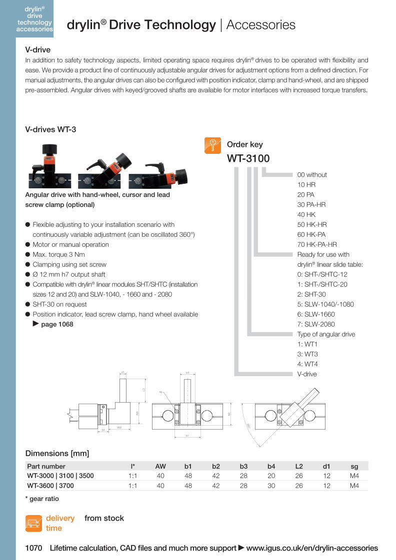
WT-3100
Flexible adjusting to your installation scenario with
continuously variable adjustment (can be oscillated 360°)
Motor or manual operation
Max. torque 3 Nm
Clamping using set screw
Ø 12 mm h7 output shaft
Compatible with drylin® linear modules SHT/SHTC (installation
sizes 12 and 20) and SLW-1040, - 1660 and - 2080
SHT-30 on request
Position indicator, lead screw clamp, hand wheel available
page 1068
Order key
Dimensions [mm]
00 without
10 HR
20 PA
30 PA-HR
40 HK
50 HK-HR
60 HK-PA
70 HK-PA-HR
Ready for use with
drylin® linear slide table:
0: SHT-/SHTC-12
1: SHT-/SHTC-20
2: SHT-30
5: SLW-1040/-1080
6: SLW-1660
7: SLW-2080
Type of angular drive
1: WT1
3: WT3
4: WT4
V-drive
AW
AWb4
b1
b2
d1 b3
sg
360°
L2
AW
AWb4
b1
b2
d1 b3
sg
360°
L2
AW
AWb4
b1
b2
d1 b3
sg
360°
L2
Part number l* AW b1 b2 b3 b4 L2 d1 sgWT-3000 | 3100 | 3500 1:1 40 48 42 28 20 26 12 M4
WT-3600 | 3700 1:1 40 48 42 28 30 26 12 M4
Angular drive with hand-wheel, cursor and lead
screw clamp (optional)
drylin® Drive Technology | Accessories
V-driveIn addition to safety technology aspects, limited operating space requires drylin® drives to be operated with flexibility and
ease. We provide a product line of continuously adjustable angular drives for adjustment options from a defined direction. For
manual adjustments, the angular drives can also be configured with position indicator, clamp and hand-wheel, and are shipped
pre-assembled. Angular drives with keyed/grooved shafts are available for motor interfaces with increased torque transfers.
V-drives WT-3
from stock
* gear ratio
06_GL6_UK_drylin_Antrieb.indd 64 26.02.13 10:48
1071
deliverytime
2-3 days
igus® (UK) Ltd | Phone (01604) 677240 Fax -245 | [email protected] | www.igus.co.ukLifetime calculation, CAD files and much more support www.igus.co.uk/en/drylin-accessories
drylin®
drive technology accessories
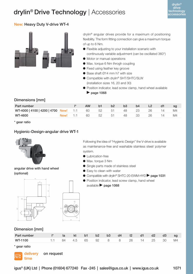
New: Heavy Duty V-drive WT-4
Dimensions [mm]
Part number l* AW b1 b2 b3 b4 L2 d1 sgWT-4000 | 4100 | 4200 | 4700 New! 1:1 60 52 51 48 23 26 14 M4
WT-4600 New! 1:1 60 52 51 48 33 26 14 M4
drylin® angular drives provide for a maximum of positioning
flexibility. The form fitting connection can give a maximum torque
of up to 6 Nm.
Flexible adjusting to your installation scenario with
continuously variable adjustment (can be oscillated 360°)
Motor or manual operations
Max. torque 6 Nm throgh coupling
Fixed using feather key groove
Base shaft Ø14 mm h7 with size
Compatible with drylin® SHT/SHTC/SLW
(installation sizes 16, 20 and 30)
Position indicator, lead screw clamp, hand wheel available
page 1068
Hygienic-Design-angular drive WT-1
angular drive with hand wheel
(optional)
Following the idea of “Hygienic Design” the V-drive is available
as maintenance-free and washable stainless steel/ polymer
system.
Lubrication-free
Max. torque 3 Nm
Single parts made of stainless steel
Easy to clean with water
Compatible with drylin® SHTC-20-EWM-HYD page 1031
Position indicator, lead screw clamp, hand wheel
available page 1068d1
l2
b3
d4
la
d3
d2
kt
b2
b1
d1
l2
b3
d4
la
d3
d2
kt
b2
b1
Part number l* la kt b1 b2 b3 d4 I2 d1 d2 d3 sg
WT-1100 1:1 84 4.5 65 92 8 8 26 14 25 30 M4
Dimension [mm]
drylin® Drive Technology | Accessories
on request
* gear ratio
* gear ratio
06_GL6_UK_drylin_Antrieb.indd 65 26.02.13 10:48
1072
delivery time
Lifetime calculation, CAD fi les and much more support www.igus.co.uk/en/drylin-accessories
2-8 days
drylin®
drive technology accessories
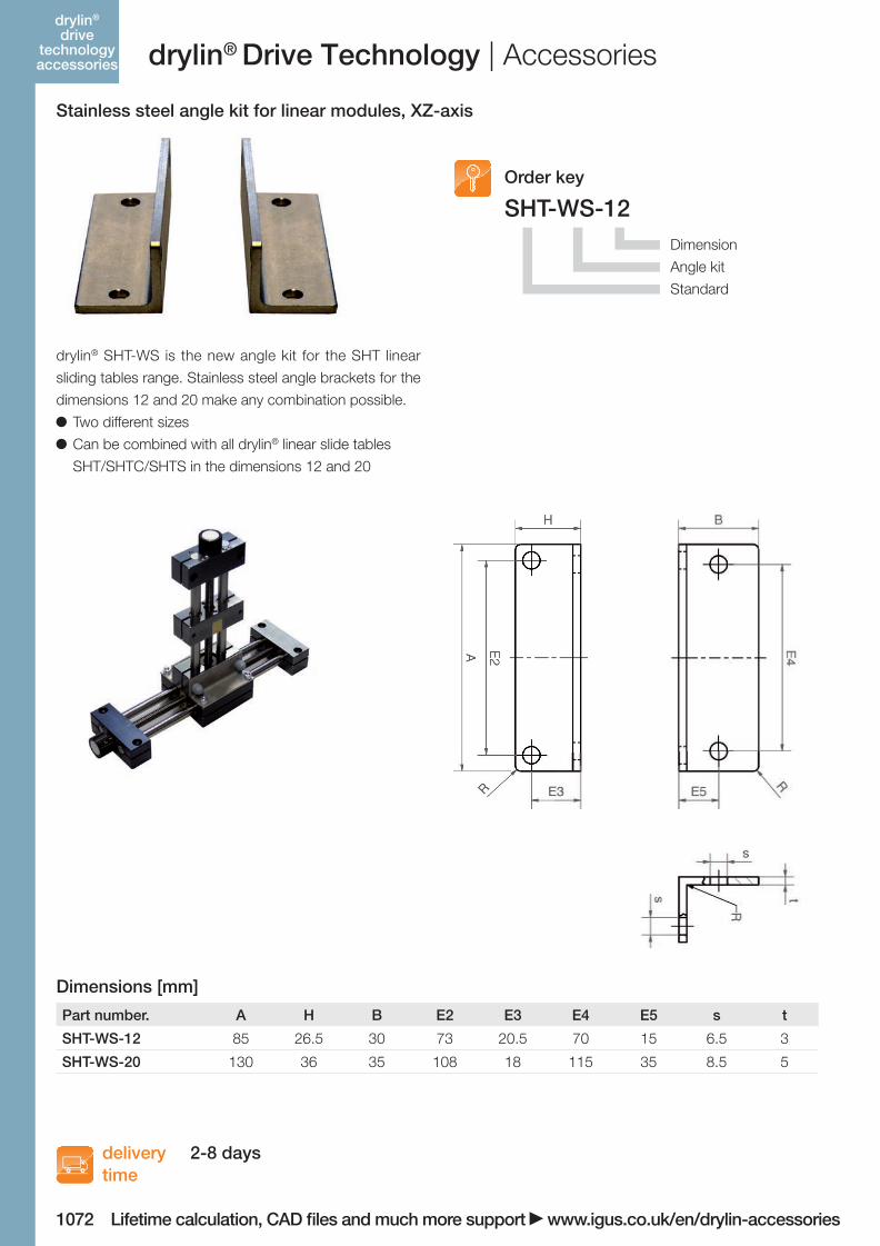
SHT-WS-12
Part number. A H B E2 E3 E4 E5 s t
SHT-WS-12 85 26.5 30 73 20.5 70 15 6.5 3
SHT-WS-20 130 36 35 108 18 115 35 8.5 5
Order key
Stainless steel angle kit for linear modules, XZ-axis
drylin® SHT-WS is the new angle kit for the SHT linear
sliding tables range. Stainless steel angle brackets for the
dimensions 12 and 20 make any combination possible.
Two different sizes
Can be combined with all drylin® linear slide tables
SHT/SHTC/SHTS in the dimensions 12 and 20
Dimension
Angle kit
Standard
Dimensions [mm]
drylin® Drive Technology | Accessories
06_GL6_UK_drylin_Antrieb.indd 66 26.02.13 10:48

1073
deliverytime
igus® (UK) Ltd | Phone (01604) 677240 Fax -245 | [email protected] | www.igus.co.ukLifetime calculation, CAD files and much more support www.igus.co.uk/en/drylin-accessories
from stock
drylin®
drive technology accessories
Part number d1 d2 d3 d4 sg E1 l1 l2 l ges. T
max
min. bending
radius
max. [Nm]
FS-06-500-Z12X120-AA New! 14H7 12h7 21 6 M4 8 17 120 500 1.8 70
FS-08-1000-Z12X120-AA New! 14H7 12h7 21 8 M4 8 17 120 1,000 2.7 90
New in this catalog!
Flexshaft
The ideal complement to drylin® linear modules. The flexshaft
enables the positioning of the hand wheel independent of the
installation position of the linear unit. Distance of 500 mm and
offset by 85°? No problem!
2 lengths (500 + 1,000 mm)
For all journal diameters (10, 12, 14 mm)
Flexible installation
Space saving
Can be combined with a bearing block page 980
Position indicator, lead screw clamp, hand wheel available
page 1068
Dimensions [mm]
l2
d2d1
l1
E1
sgl ges.
d4
d3drylin® Drive Technology | Accessories
Example of the function of an
offset operating unit
06_GL6_UK_drylin_Antrieb.indd 67 26.02.13 10:49