Embed Size (px)
Citation preview
International Journal of Scientific & Engineering Research, Volume 6, Issue 6, June-2015 824 ISSN 2229-5518
IJSER © 2015 http://www.ijser.org
Flexural Finite Element Analysis of Reinforced Concrete Beams Strengthened by NSM CFRP
Rods and Strips Dr. Qassim M. Shaker[1], Dr. Muhammad A. Attiya[2], Dr. Hayder H. H. Kamonna[3]
Abstract— The present study deals with numerical analysis of reinforced (RC) simply supported beam strengthened by carbon fiber reinforced polymer (CFRP) element. The two commonly used techniques near surface mounted (NSM) and externally bonded reinforcement (EBR) are considered. For the NSM technique, the two configurations of strengthening by CFRP, rod and sheet, have been used, while Sheet type at bottom surface of beam is used for EBR technique. ANSYS V15 has been employed to achieve the present work. Also study is focused on investigation of some parameters that may affect the performance of strengthened RC beam. Parameter studied here are; effect of NSM CFRP ratio, configuration of CFRP type of reinforcement (rod or sheet), distribution of NSM CFRP rod area through beam width and the effect of simulation of epoxy grove.
The results revealed that using higher ratios of CFRP results in considerable improvement in ultimate load capacity, an increment up to 180% in ultimate load capacity can be achieved with increasing the NSM rod ratio from 0.047% to 0.377%. Slight effect of using CFRP sheet instead of CFRP rod has been obtained, the range of influence was 94% - 123%. Also use different diameters of NSM CFRP rod for the same ratio of area decreases the post- cracking stiffness response with significant decrease in ultimate load capacity. The analysis yields that use various model of epoxy-groove between CFRP and concrete have little effect on the behaviour of strengthened beam.
Index Terms— Reinforced Concrete Beam, Carbon Fiber, Strengthened, Nonlinear Analysis, Finite Element Analysis
—————————— ——————————
1 INTRODUCTION he near-surface mounted (NSM) technique system has been adopted in the last years to increase the load carry-
ing capacity of concrete members. According to the NSM technique, FRP’s are introduced into saw cut grooves opened on the concrete cover of the elements to be strengthened. Typ-ically, these grooves are filled with an epoxy adhesive, work-ing as bond agent between FRP and concrete. The initial re-search work on NSM technique was reported by Blaschko and Zilch (1999) using CFRP strips inserted into grooves cut at the surface of concrete specimens. The specimens were tested in a double shear configuration. Test results showed that strength-ening using NSM CFRP strips has a greater anchoring capacity compared to externally bonded CFRP strips. De Lorenzis and Nanni (2002) investigated the structural performance of simp-ly supported reinforced concrete beams strengthened with NSM glass and carbon FRP rods. Both flexural and shear strengthening were examined. Hassan and Rizkalla (2003) investigated the feasibility of using different strengthening techniques as well as different types of FRP for flexural
strengthening of large scale prestressed concrete specimens. Sena-Cruz et al (2012) studied the influence of the bond length, the groove width and depth, and the number of wet-dry cycles on the bond performance by taking thirty five cubic specimens. Dias and Barros(2013) studied the shear strength-ening of reinforced concrete beams with NSM CFRP lami-nates, the parameters investigated are (concrete strength, per-centage of existing steel stirrups, percentage and inclination of the CFRP laminates, and existence of cracks when the RC beams are shear strengthened with NSM CFRP). An analytical model is proposed to characterize the behaviour of concrete structures strengthened with NSM FRP bars and sheet.
2 Description of Test Specimens Six beams have been investigated in the present work which tested by Jung et al (2005). These specimens were, one CON-TROL specimen (without strengthening), two EBR (strength-ened by Externally bonded reinforcement CFRP sheets and CFRP strips respectively) specimens CPL-50-BOND and SH-BOND, two specimens were strengthened with NSM CFRP strips (NSM-PL-15 and PL-MI-20) and one specimen was strengthened with NSM CFRP rod (ROD-MI-20). All tested beams had a longitudinal steel D10 (φ9.53mm) of SD40 have been arranged with steel ratio of 0.0041 and a layer of three D13 (φ12.7mm) has been arranged as compression reinforce-
T
———————————————— [1] Lecturer Dr. Qassim M. Shaker, University of Kufa\ College of Engi-
neering \ Civil Department\E-mail: [email protected] [2] Lecturer Dr. Muhammad Abed Attiya, University of Kufa\ College of
Engineering \ Civil Department \E-mail: [email protected]
[3] Lecturer Dr. Hayder H. H. Kamonna, University of Kufa\ College of Engineering \ Civil Department \ E-mail: [email protected]
IJSER
International Journal of Scientific & Engineering Research, Volume 6, Issue 6, June-2015 825 ISSN 2229-5518
IJSER © 2015 http://www.ijser.org
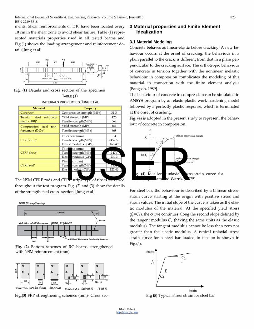
ments. Shear reinforcements of D10 have been located every 10 cm in the shear zone to avoid shear failure. Table (1) repre-sented materials properties used in all tested beams and Fig.(1) shows the loading arrangement and reinforcement de-tails[Jung et al].
TABLE (1) MATERIALS PROPERTIES JUNG ET AL
Material Property Concrete* Compressive strength (MPa) 31.3 Tension steel reinforce-ment (D10)*
Yield strength (MPa) 426 Tensile strength(MPa) 562
Compression steel rein-forcement (D13)*
Yield strength (MPa) 481 Tensile strength(MPa) 608
CFRP strip* Thickness (mm) 1.4 Tensile strength(MPa) 2452.59 Elastic modulus (GPa) 165.49
CFRP sheet* Thickness (mm) 0.11 Tensile strength(MPa) 3479 Elastic modulus (GPa) 230.3
CFRP rod* Diameter (mm) 9 Tensile strength(MPa) 1878 Elastic modulus(GPa) 121.43
The NSM CFRP rods and CFRP strips type of fibers was used throughout the test program. Fig. (2) and (3) show the details of the strengthened cross- sections[Jung et al].
3 Material properties and Finite Element Idealization
3.1 Material Modeling Concrete behaves as linear-elastic before cracking. A new be-haviour occurs at the onset of cracking, the behaviour in a plain parallel to the crack, is different from that in a plain per-pendicular to the cracking surface. The orthotropic behaviour of concrete in tension together with the nonlinear inelastic behaviour in compression complicates the modeling of this material in connection with the finite element analysis [Bangash, 1989]. The behaviour of concrete in compression can be simulated in ANSYS program by an elasto-plastic work hardening model followed by a perfectly plastic response, which is terminated at the onset of crushing. Fig. (4) is adopted in the present study to represent the behav-iour of concrete in compression.
For steel bar, the behaviour is described by a bilinear stress-strain curve starting at the origin with positive stress and strain values. The initial slope of the curve is taken as the elas-tic modulus of the material. At the specified yield stress (fRyR=CR1R), the curve continues along the second slope defined by the tangent modulus CR2R (having the same units as the elastic modulus). The tangent modulus cannot be less than zero nor greater than the elastic modulus. A typical uniaxial stress strain curve for a steel bar loaded in tension is shown in Fig.(5).
Fig. (2) Bottom schemes of RC beams strengthened with NSM reinforcement (mm)
Fig.(3) FRP strengthening schemes (mm)- Cross sec-
Fig. (4) Idealized uniaxial stress-strain curve for concrete (Willam and Warnke, 1975)
Stress
Strain
fy
E C1
C2 1
Fig (5) Typical stress strain for steel bar
Fig. (1) Details and cross section of the specimen
IJSER
International Journal of Scientific & Engineering Research, Volume 6, Issue 6, June-2015 826 ISSN 2229-5518
IJSER © 2015 http://www.ijser.org
Linear elastic orthotropic properties of the FRP composite are assumed thought out this study as shown in Fig.(6). In addi-tion, full bond between the concrete and CFRPs is assumed.
0 0.01 0.02 0.03 0.040.005 0.015 0.025 0.035
strain
0
1000
2000
3000
4000
500
1500
2500
3500
stre
ss [M
Pa]
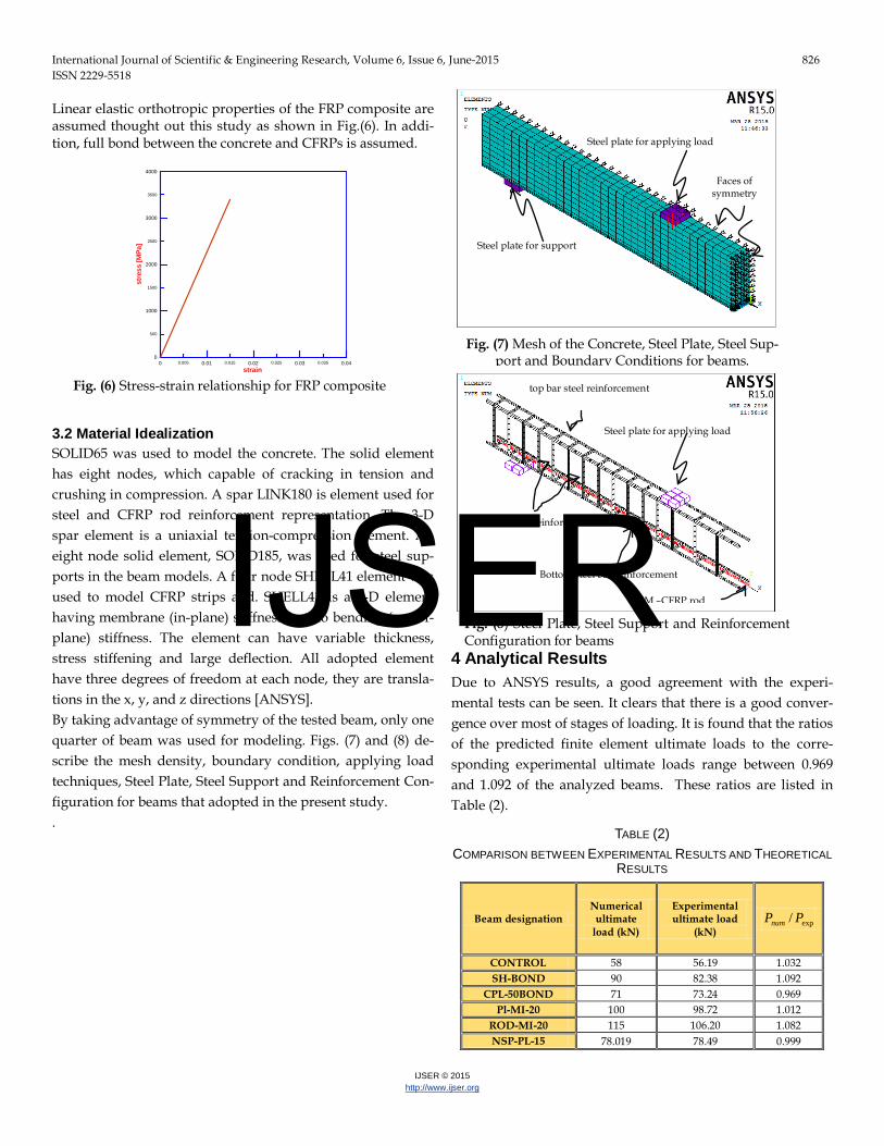
3.2 Material Idealization SOLID65 was used to model the concrete. The solid element has eight nodes, which capable of cracking in tension and crushing in compression. A spar LINK180 is element used for steel and CFRP rod reinforcement representation. The 3-D spar element is a uniaxial tension-compression element. An eight node solid element, SOLID185, was used for steel sup-ports in the beam models. A four node SHELL41 element was used to model CFRP strips and. SHELL41 is a 3-D element having membrane (in-plane) stiffness but no bending (out-of-plane) stiffness. The element can have variable thickness, stress stiffening and large deflection. All adopted element have three degrees of freedom at each node, they are transla-tions in the x, y, and z directions [ANSYS]. By taking advantage of symmetry of the tested beam, only one quarter of beam was used for modeling. Figs. (7) and (8) de-scribe the mesh density, boundary condition, applying load techniques, Steel Plate, Steel Support and Reinforcement Con-figuration for beams that adopted in the present study. .
4 Analytical Results Due to ANSYS results, a good agreement with the experi-mental tests can be seen. It clears that there is a good conver-gence over most of stages of loading. It is found that the ratios of the predicted finite element ultimate loads to the corre-sponding experimental ultimate loads range between 0.969 and 1.092 of the analyzed beams. These ratios are listed in Table (2).
TABLE (2) COMPARISON BETWEEN EXPERIMENTAL RESULTS AND THEORETICAL
RESULTS
Beam designation Numerical
ultimate load (kN)
Experimental ultimate load
(kN) exp/ PPnum
CONTROL 58 56.19 1.032 SH-BOND 90 82.38 1.092
CPL-50BOND 71 73.24 0.969 Pl-MI-20 100 98.72 1.012
ROD-MI-20 115 106.20 1.082 NSP-PL-15 78.019 78.49 0.999
Fig. (7) Mesh of the Concrete, Steel Plate, Steel Sup-port and Boundary Conditions for beams.
Fig. (8) Steel Plate, Steel Support and Reinforcement Configuration for beams
Steel plate for applying load
Steel plate for support
Faces of symmetry
Steel plate for applying load
top bar steel reinforcement
Bottom steel bar reinforcement
NSM –CFRP rod
Shear steel bar reinforcement
Fig. (6) Stress-strain relationship for FRP composite
IJSER
International Journal of Scientific & Engineering Research, Volume 6, Issue 6, June-2015 827 ISSN 2229-5518
IJSER © 2015 http://www.ijser.org
The experimental and numerical Load-deflection curves ob-tained for the tested beams are shown in Figs. (9) to (14). In the linear range, the numerical load-deflection curve is stiffer than the experimental curve. This can be attributed to that the con-tribution of CFRP on the stiffness of the structure, while in actual structure that contribution will begin after the occurring of the first crack. This stiff solution will be decrease as decreas-ing the CFRP ratio or decreasing the position of CFRP from tensile surface. Also it can be seen that the axial ultimate load values obtained from the finite element analysis are slightly higher than the actual experimental ultimate loads.
0 20 40 60 80Deflection (mm)
0
20
40
60
10
30
50
70
Load
(kN
)
ANSYSJung et al.
-0 4 8 12 16 20Deflection (mm)
0
20
40
60
80
Load
(kN
)
ANSYSJung et al.
0 10 20 30 40 50Deflection (mm)
0
20
40
60
80
100
Load
(kN
)
ANSYSJung et al.
0 20 40 60Deflection (mm)
0
20
40
60
80
Load
(kN
)
ANSYSJung et al.
-0 20 40 60 80Deflection (mm)
0
40
80
120
Load
(kN
)
ANSYSJung et al.
0 20 40 60Deflection (mm)
0
40
80
120
20
60
100
Load
(kN
)
ANSYSJung et al.
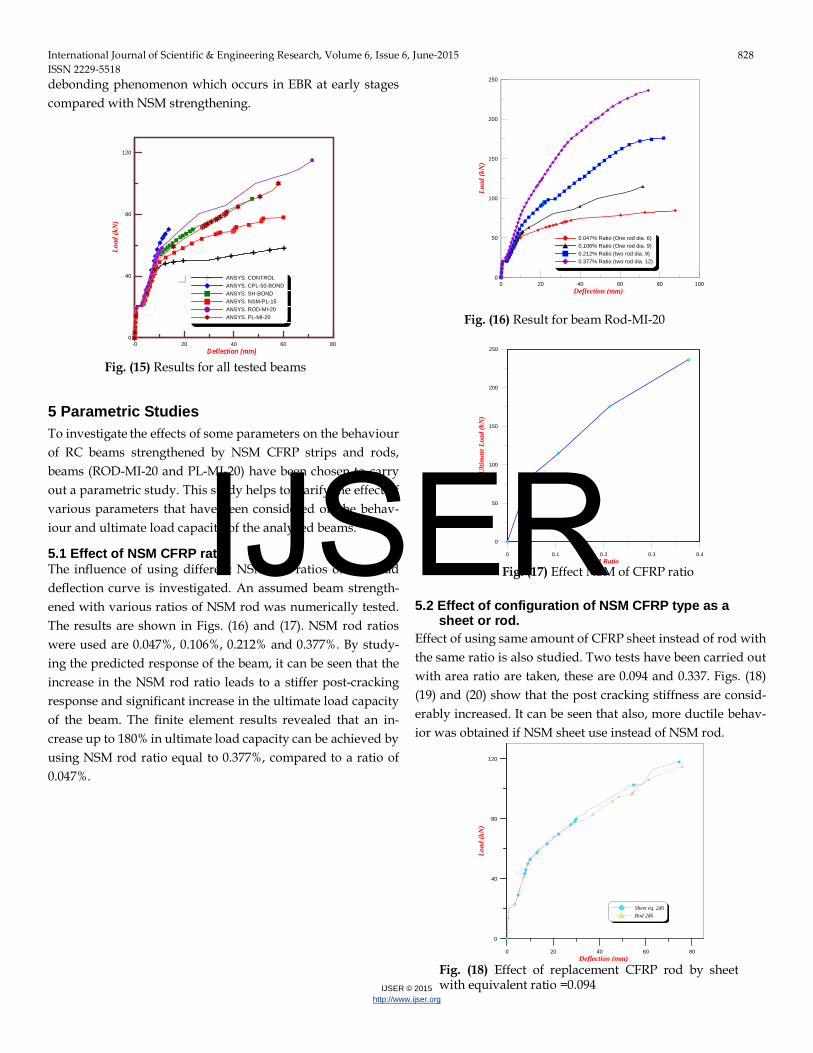
Fig. (15) explains the different in the ultimate load and deflec-tion of all specimens which used in this study. From figure we can note the same behaviour of all specimens in linear range which about (24 kN). Then, after these load the behaviour was deferent for each specimen. Where specimens (EBR) CPL-50-BOND and SH-BOND, the load-deflection curve stiffer than NSM specimens, but the NSM specimen have ultimate load and ductility more than EBR specimens. This may due to the
Fig. (9) Results for control beam
Fig. (10) Results for beam (CPL-50-BOND)
Fig. (11) Results for beam (SH-BOND)
Fig. (12) Results for beam (NSM-PL-15)
Fig. (13)Results for beam (ROD-MI-20)
Fig. (14) Results for beam (PL-MI-20)
IJSER
International Journal of Scientific & Engineering Research, Volume 6, Issue 6, June-2015 828 ISSN 2229-5518
IJSER © 2015 http://www.ijser.org
debonding phenomenon which occurs in EBR at early stages compared with NSM strengthening.
-0 20 40 60 80Deflection (mm)
0
40
80
120
Load
(kN
)
ANSYS. CONTROLANSYS. CPL-50-BONDANSYS. SH-BONDANSYS. NSM-PL-15ANSYS. ROD-MI-20ANSYS. PL-MI-20
5 Parametric Studies To investigate the effects of some parameters on the behaviour of RC beams strengthened by NSM CFRP strips and rods, beams (ROD-MI-20 and PL-MI-20) have been chosen to carry out a parametric study. This study helps to clarify the effect of various parameters that have been considered on the behav-iour and ultimate load capacity of the analyzed beams.
5.1 Effect of NSM CFRP ratio The influence of using different NSM rod ratios on the load deflection curve is investigated. An assumed beam strength-ened with various ratios of NSM rod was numerically tested. The results are shown in Figs. (16) and (17). NSM rod ratios were used are 0.047%, 0.106%, 0.212% and 0.377%. By study-ing the predicted response of the beam, it can be seen that the increase in the NSM rod ratio leads to a stiffer post-cracking response and significant increase in the ultimate load capacity of the beam. The finite element results revealed that an in-crease up to 180% in ultimate load capacity can be achieved by using NSM rod ratio equal to 0.377%, compared to a ratio of 0.047%.
0 20 40 60 80 100Deflection (mm)
0
50
100
150
200
250
Load
(kN
)
0.047% Ratio (One rod dia. 6)0.106% Ratio (One rod dia. 9)0.212% Ratio (two rod dia. 9)0.377% Ratio (two rod dia. 12)
0 0.1 0.2 0.3 0.4NSM Ratio
0
50
100
150
200
250
Ulti
mat
e Lo
ad (k
N)
5.2 Effect of configuration of NSM CFRP type as a sheet or rod.
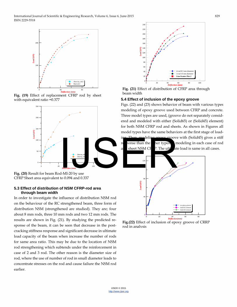
Effect of using same amount of CFRP sheet instead of rod with the same ratio is also studied. Two tests have been carried out with area ratio are taken, these are 0.094 and 0.337. Figs. (18) (19) and (20) show that the post cracking stiffness are consid-erably increased. It can be seen that also, more ductile behav-ior was obtained if NSM sheet use instead of NSM rod.
0 20 40 60 80Deflection (mm)
0
40
80
120
Load
(kN
)
Sheet eq. 2d6Rod 2d6
Fig. (15) Results for all tested beams
Fig. (17) Effect NSM of CFRP ratio
Fig. (18) Effect of replacement CFRP rod by sheet with equivalent ratio =0.094
Fig. (16) Result for beam Rod-MI-20
IJSER
International Journal of Scientific & Engineering Research, Volume 6, Issue 6, June-2015 829 ISSN 2229-5518
IJSER © 2015 http://www.ijser.org
0 40 80Deflection (mm)
0
100
200
Load
(kN
)
Sheet Eq. 2d12Rod 2d12
0 40 80 120Deflection (mm)
0
50
100
150
200
250
Load
(kN
)
Sheet eq. 2d6Sheet eq. 2d12
5.3 Effect of distribution of NSM CFRP-rod area through beam width
In order to investigate the influence of distribution NSM rod on the behaviour of the RC strengthened beam, three form of distribution NSM (strengthened are studied). They are; four about 8 mm rods, three 10 mm rods and two 12 mm rods. The results are shown in Fig. (21). By studying the predicted re-sponse of the beam, it can be seen that decrease in the post- cracking stiffness response and significant decrease in ultimate load capacity of the beam when increase the number of rods for same area ratio. This may be due to the location of NSM rod strengthening which subtends under the reinforcement in case of 2 and 3 rod. The other reason is the diameter size of rod, where the use of number of rod in small diameter leads to concentrate stresses on the rod and cause failure the NSM rod earlier.
0 20 40 60 80 100Deflection (mm)
0
20
40
60
80
100
120
140
160
180
200
220
240
Load
(kN
)
4-rod 8.5 mm diameter3-rod 10 mm diameterLine/Scatter Plot 2
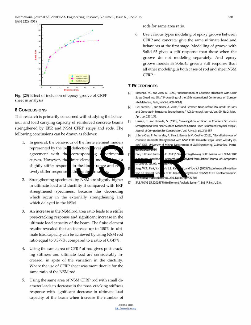
5.4 Effect of inclusion of the epoxy groove Figs. (22) and (23) shows behavior of beam with various types modeling of epoxy groove used between CFRP and concrete. Three model types are used, (groove do not separately consid-ered and modeled with either (Solid65) or (Solid45) element) for both NSM CFRP rod and sheets. As shown in Figures all model types have the same behaviors at the first stage of load-ing. Then, modeling epoxy groove with (Solid45) gives a stiff response than the other types of modeling in each case of rod and sheet NSM CFRP. The ultimate load is same in all cases.
-0 20 40 60 80Deflection(mm)
0
40
80
120
Load
(kN
)
no epoxy grooveSolid 65 elementSolid 45 element
Fig. (19) Effect of replacement CFRP rod by sheet with equivalent ratio =0.377
Fig. (20) Result for beam Rod-MI-20 by use CFRP Sheet area equivalent to 0.094 and 0.337
Fig. (21) Effect of distribution of CFRP area through beam width
Fig.(22) Effect of inclusion of epoxy groove of CRRP rod in analysis
IJSER
International Journal of Scientific & Engineering Research, Volume 6, Issue 6, June-2015 830 ISSN 2229-5518
IJSER © 2015 http://www.ijser.org
-0 10 20 30 40 50 60 70Deflection (mm)
0
10
20
30
40
50
60
70
80
90
100
110
Load
(kN
)
no epoxy grooveSolid 65 elementSolid 45 element
6 CONCLUSIONS This research is primarily concerned with studying the behav-iour and load carrying capacity of reinforced concrete beams strengthened by EBR and NSM CFRP strips and rods. The following conclusions can be drawn as follows:
1. In general, the behaviour of the finite element models represented by the load-deflection curves shows good agreement with the corresponding experimental curves. However, the finite element models show a slightly stiffer response in the linear range and rela-tively stiffer response in the nonlinear ranges.
2. Strengthening specimens by NSM are slightly higher in ultimate load and ductility if compared with ERP strengthened specimens, because the debonding which occur in the externally strengthening and which delayed in the NSM.
3. An increase in the NSM rod area ratio leads to a stiffer post-cracking response and significant increase in the ultimate load capacity of the beam. The finite element results revealed that an increase up to 180% in ulti-mate load capacity can be achieved by using NSM rod ratio equal to 0.377%, compared to a ratio of 0.047%.
4. Using the same area of CFRP of rod gives post crack-ing stiffness and ultimate load are considerably in-creased, in spite of the variation in the ductility. Where the use of CFRP sheet was more ductile for the same ratio of the NSM rod.
5. Using the same area of NSM CFRP rod with small di-ameter leads to decrease in the post- cracking stiffness response with significant decrease in ultimate load capacity of the beam when increase the number of
rods for same area ratio.
6. Use various types modeling of epoxy groove between CFRP and concrete; give the same ultimate load and behaviors at the first stage. Modelling of groove with Solid 65 gives a stiff response than those when the groove do not modeling separately. And epoxy groove models as Solid45 gives a stiff response than all other modeling in both cases of rod and sheet NSM CFRP.
7 REFERENCES [1] Blaschko, M., and Zilch, K., 1999, "Rehabilitation of Concrete Structures with CFRP
Strips Glued Into Slits," Proceedings of the 12th International Conference on Compo-site Materials, Paris, July 5-9. (CD-ROM)
[2] De Lorenzis, L., and Nanni, A., 2002, "Bond Between Near- urface Mounted FRP Rods and Concrete in Structures Strengthening," ACI Strnctural Journal, Vol. 99, No.2, Mar.-Apr., pp. 123·1 32.
[3] Hassan, T. and Rizkalla, S. (2003), “Investigation of Bond in Concrete Structures Strengthened with Near Surface Mounted Carbon Fiber Reinforced Polymer Strips”, Journal of Composites for Construction, Vol. 7, No. 3, pp. 248-257
[4] J. Sena-Cruz, P. Fernandes, P. Silva, J. Barros & M. Coelho (2012), " Bond behaviour of concrete elements strengthened with NSM CFRP laminate strips under wet-dry cy-cles" ISISE, University of Minho, Department of Civil Engineering, Guimarães, Portu-gal. pp.1023-1030
[5] Dais, S.J.E and Barros,J.A.O.,2013," Shear strengthening of RC beams with NSM CFRP laminates: Experimental research and analytical formulation" Journal of Composites structures, vol. 99, May.,pp.477-490
[6] Jung, W.T., Park, Y.H., Park, J.S., Kang J.-Y., and You Y.J. (2005)"Experimental Investiga-tion on Flexural Behavior of RC Beams Strengthened by NSM CFRP Reinforcements", ACI Special Publications, Vol. 230, No.46, pp.795-805
[7] SAS ANSYS 15, (2014)“Finite Element Analysis System”, SAS IP, Inc., U.S.A,
Fig. (23) Effect of inclusion of epoxy groove of CRFP sheet in analysis
IJSER


![Transactional Contention Management as a Non-Clairvoyant Scheduling Problem Alessia Milani [Attiya et al. PODC 06] [Attiya and Milani OPODIS 09]](https://img.dokumen.tips/doc/110x75/56649ce25503460f949ada56/transactional-contention-management-as-a-non-clairvoyant-scheduling-problem.jpg)


