Embed Size (px)
Citation preview
(Issue October 2002)
Com
pact
wire
less c
ontro
l pan
el wi
th b
uilt-
in d
igita
l com
mun
icato
r
DDDOOOMMMOOONNNIIIAAALLL888000000++++++ RRRaaannngggeee
Installation & programming instructions
Product meets the requirements of CEM provisions on electrical safety and compatibility. Product meets the requirements of R&TTE specifications
EKZ004400f
EKZ004400F
Domonial 800++ Installation Manual - 10/2002 www.secom.tm.fr
2
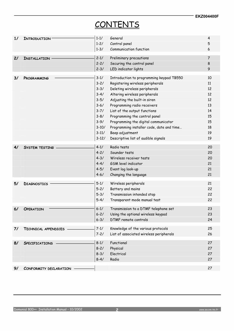
CONTENTS 1/ INTRODUCTION 1-1/ General 4 1-2/ Control panel 5 1-3/ Communication function 6
2/ INSTALLATION 2-1/ Preliminary precautions 7 2-2/ Securing the control panel 8 2-3/ LED indicator lights 9
3/ PROGRAMMING 3-1/ Introduction to programming keypad TB550 10 3-2/ Registering wireless peripherals 11 3-3/ Deleting wireless peripherals 12 3-4/ Altering wireless peripherals 12 3-5/ Adjusting the built-in siren 12 3-6/ Programming radio receivers 13 3-7/ List of the output functions 14 3-8/ Programming the control panel 15 3-9/ Programming the digital communicator 15 3-10/ Programming installer code, date and time… 18 3-11/ Beep adjustment 19 3-12/ Descriptive list of audible signals 19
4/ SYSTEM TESTING 4-1/ Radio tests 20 4-2/ Sounder tests 20 4-3/ Wireless receiver tests 20 4-4/ GSM level indicator 21 4-5/ Event log look-up 21 4-6/ Changing the language 21
5/ DIAGNOSTICS 5-1/ Wireless peripherals 21 5-2/ Battery and mains 22 5-3/ Transmission intended stop 22 5-4/ Transparent mode manual test 22
6/ OPERATION 6-1/ Transmission to a DTMF telephone set 23 6-2/ Using the optional wireless keypad 23 6-3/ DTMF remote controls 24
7/ TECHNICAL APPENDICES 7-1/ Knowledge of the various protocols 25 7-2/ List of associated wireless peripherals 26
8/ SPECIFICATIONS 8-1/ Functional 27 8-2/ Physical 27 8-3/ Electrical 27 8-4/ Radio 27
9/ CONFORMITY DECLARATION 27

EKZ004400F
Domonial 800++ Installation Manual - 10/2002 www.secom.tm.fr
3
1 - INTRODUCTION
1-1 General The CRT800++ (or PCT800++) is a wireless control panel with a built in siren and digital communicator. The CRI800++ (or PCI800++) is a wireless control panel with a built in siren, digital communicator and audio verification. The radio link between the various components of the system facilitates easy installation without the need for most cabling. Arming and disarming can be controlled by both wireless keypads and wireless keyfobs from the SÉCURITÉ COMMUNICATIONS 800 range. Programming of the control panel and digital communicator can be carried out locally via the TB550 terminal or a PC running Windows 95 or 98. Programming is also possible via the PSTN network and a Domocom (1) modem. A 500-event log file can be browsed through using the TB550 or a PC. The CRT/CRI800++ has an built in mains supply and a 4V 3.5A/h back-up battery (included). System setting are saved in the case of total power loss (mains and battery). Mimic diagram
1 Special model of modem used for Domonial Range
Control panel 800++
Wireless peripherals from the 800 Secom range (keypads, keyfobs, PIR detectors, door/window contacts, technical detectors…) Maximum : 20 detectors 2 keypads 4 keyfobs (4 buttons) + 1 response keyfob 2 LCD keypad DTMF remote control
DETECTION ANALYSIS SIGNALLING
Wireless receivers. Maximum : 4* Wireless siren from the Secom 800 range Maximum : 4* sirens (internal or external). Local audio verification (CRI/PCI800++ only) Built in siren Telephone transmission by PSTN Network or GSM Network (optional) (*) :Up to 4 devices of these type
.
.
.

EKZ004400F
Domonial 800++ Installation Manual - 10/2002 www.secom.tm.fr
4
1-2 Control panel The control panel, depending of the programming, covers:
- 1 Total "zone" (or Main) - 1 Part "zone" - 1 Annex or Perimeter "zone"
Arming / Disarming
The surveillance of the zones can be controlled as follows :
Zones Keypad Keyfob Remote DTMF Code by phone
By DOMOSTATION software
Total ARMING Y Y Y(1) Y(1) Partial ARMING Y Y Y(1) Y(1) Annex ZONE ARMING Y Y Y(1) Y(1) Total DISARMING Y Y N Y(1) Annex zone DISARMING Y Y N Y(1)
Users : The control panel allows up to 10 users (including master) ; The keyfobs/keypads and the codes (except CLI800HF) are assigned by the user :
Functions \ Users Master 1 2 3 4 5 6 7 8 9 Allocate user TCX04HF / TC805HF Y Y Y Y Y Y Y Y Y Y Allocate code on keypad CLBX00HF Y Y Y Y Y Y Y Y Y Y Supervised user Y/N Y/N Y/N Y/N Y/N Y/N Y/N Y/N Y/N Y/N The user’s name is stored in the event log and actions of the “supervised” user are reported to the monitoring station by a code.
Alarm detection: The triggering of wireless detectors and of certain internal inputs (refer to records table on §3.14) can be subordinated
to the arming status.
The detectors can be programmed : - with a entry/exit delay programmable from 0 to 90 seconds (for total, part or annex zone). - hybrid (delay or instant trigger depending on which input is activated first) = Mixed. - direct trigger (Total, partial, annex or 24/24)
o Each zone can be armed from a remote multifrequency telephone set(1) (via PSTN or GSM(2) network).
Several sounder operating modes are available: - standard sounder. - sounder activated upon intrusion or loss of PSTN line. Sounding duration can be programmed from 0 to 240 seconds. Activation of the sounder can also be postponed until after the alarm signal has been transmitted.
(1) These functions can be disabled, depending on the country rules. (2) Only when using the optional GSM unit
T
P
A

EKZ004400F
Domonial 800++ Installation Manual - 10/2002 www.secom.tm.fr
5
1-3 Transmitter function The Domonial 800++ control panel includes a digital communicator designed to send information, via the PSTN or GSM (optional) network to:
- an Alarm Receiving Center using the following formats: Secom3, Surtec, Cesa, Stratel, Contact ID (3). - a telephone set.
The Domonial 800++ control panel can receive and integrate a full set of parameters from a remote position via the PSTN network. Specific software and a Domocom modem are necessary (depending of country rules).
Six call numbers (designated: A, B, C, D, E, F) each containing a maximum of 17 digits can be programmed (* for pause).
The call sequences are as follows:
AABBCCEEFFABCEF (4) The Domonial 800++ makes 15 attempts dialling A tel. N° (2 times) then B tel. N° (2 times) then C tel. N° (2 times) … then E etc Telephone number D is used only for connection to an automated maintenance host. The telephone number D must not be an alarm receiver telephone number. The telephone numbers E and F are used for transmission by GSM network
A dialling prefix (within the maximum of 17 digits ) can be programmed when a telephone exchange or a telephone card is used The call sequence can be modified by programming the Domonial 800++ via the PC software. The PCI or CRI800++ model includes a audio verification system.
It is possible to activate automation functions and surveillance arming (as it is programmed) via of a DTMF telephone set.
The telephone line interface has built-in voltage surge protection and phone line failure detection.
(3) For others formats : please, consult us. (4) Depending on software versions
GSM network
DOMONIAL800++ Tone dialling telephone set
Digital Alarm Receiver (at monitoring station)
6 C
ALL
NU
MB
ERS
DTM
F TE
LEC
OM
. LI
NE
PRO
TEC
T.
Remote maintenance station
PSTN network
Optional GSM unit
CRI / PCI model only
List
en.
Mod
e
AlarmReceiving
Center(ARC)

EKZ004400F
Domonial 800++ Installation Manual - 10/2002 www.secom.tm.fr
6
2 – INSTALLION 2-1 Preliminary precautions
The circuit board uses advanced technology CMOS circuits, as with any other electronic devices, these circuits are sensitive to electrostatic shocks.
o Before touching the board or its circuits, discharge the electrostatic current by touching the earthed box base. Characteristics of a radio transmission Like light, radio waves are propagated in a straight line. They can be attenuated when sent through certain materials (wood, Artex, brick, concrete, steel reinforcements) and even reflected by metal surfaces (mirror, steel sheeting, aluminium steam-arrestor, fine-mesh wire-netting). It is therefore obvious that the quality and range of radio links between the various components largely depends on the existing environmental characteristics (nature and thickness of the neighbouring materials). In the open (without any obstructions) the radio transmitter range is more than 150 m. Indoors, the range is reduced (by 30 to 50% as an average) by the various obstructions. The four diagrams (opposite) show radio wave behaviour as a function of the interfering material: Checks before installation The above paragraph demonstrates that radio wave behaviour is not necessarily identical in every premise therefore, before securing the various components of the system, the following tests should be made :
test the radio link by positioning each peripheral unit and the control panel in their anticipated final locations (use the "radio recept." caption in the main menu). It is not necessary to record the peripheral at this stage.
using the field meter, check the received radio signal strength for each peripheral. For a reliable radio communication a minimum level of 2 boxes is recommended. If such a signal strength cannot be obtained, move the device a few inches or slightly move the control panel.
Built-in field meter To help you find the best position for the system components, the Domonial 800++ control panel has a radio field meter of the RSSI type. This enables you to check the strength of the received radio signal. Scaled from 1 to 10, this information is delivered during the test and record phases. Therefore, to make the best use of this function, it must be carried out when the transmitter is in its final location.
Warning : Any work inside the CRT/CRI800++ control panelenclosure must be carried out by qualified personnel :
ELECTRIC SHOCK HAZARD
Low attenuation Medium attenuation
EKZ004400F
Domonial 800++ Installation Manual - 10/2002 www.secom.tm.fr
7
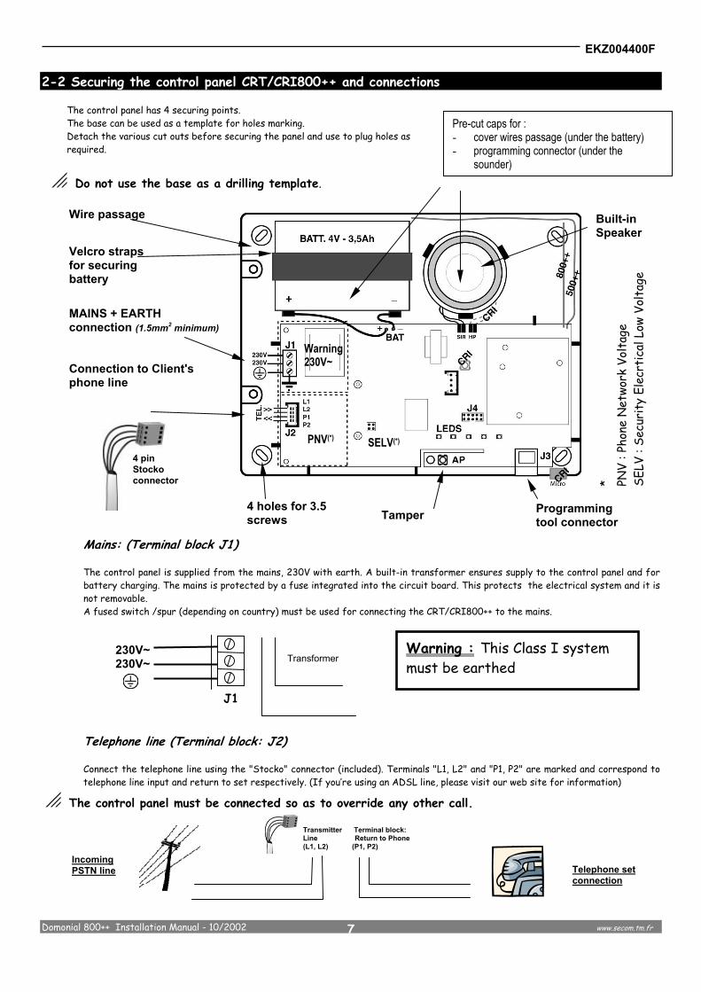
2-2 Securing the control panel CRT/CRI800++ and connections
The control panel has 4 securing points. The base can be used as a template for holes marking. Detach the various cut outs before securing the panel and use to plug holes as required.
o Do not use the base as a drilling template.
Mains: (Terminal block J1)
The control panel is supplied from the mains, 230V with earth. A built-in transformer ensures supply to the control panel and for battery charging. The mains is protected by a fuse integrated into the circuit board. This protects the electrical system and it is not removable. A fused switch /spur (depending on country) must be used for connecting the CRT/CRI800++ to the mains.
Telephone line (Terminal block: J2)
Connect the telephone line using the "Stocko" connector (included). Terminals "L1, L2" and "P1, P2" are marked and correspond to telephone line input and return to set respectively. (If you’re using an ADSL line, please visit our web site for information)
o The control panel must be connected so as to override any other call.
Incoming PSTN line
Transmitter Terminal block: Line Return to Phone (L1, L2) (P1, P2)
Wire passage
Velcro straps for securing battery
230V~ 230V~
J1
Transformer Warning : This Class I system must be earthed
Pre-cut caps for : - cover wires passage (under the battery) - programming connector (under the
sounder)
MAINS + EARTH connection (1.5mm2 minimum) Connection to Client's phone line
Built-in Speaker
4 holes for 3.5 screws Tamper Programming
tool connector
Telephone set connection
4 pin Stocko connector
PNV(*)
Warning 230V~
SELV(*)
* PNV
: Pho
ne N
etwo
rk V
olta
ge
SELV
: Se
curi
ty E
lecr
tica
l Low
Vol
tage

EKZ004400F
Domonial 800++ Installation Manual - 10/2002 www.secom.tm.fr
8
Serial port (J3)
A serial port is available to connect the programming tool or a personal computer (with optional cord) via an RJ45 connector. Cable reference : CAB550PC (or CAB550PALM for the connection with a PDA computer). The serial cable/PDA is not included
Battery connection: (Red wire + and Black wire - with lugs)
The power supply must be backed up by a 4V-3.5Ah battery (included) to maintain system operation in case of mains failure. Once the battery has been connected the system will not be initialised until mains connection.
o Do not leave the battery connected to the control panel without the mains being connected (e.g. storage before installation). In this case power used would be 1mA. System parameter back up by EEPROM requires no power supply.
2-3 LED indicator lights
5 LED indicators show the control panel & transmitter status.
State / Indicator Mains Power Arm/Disarm Perimeter fault Alarm memory Technical alarm Off
No mains power
No zone armed No fault No alarm No technical alarm
Slow Flashing (2s-2s)
Cover tamper opened
Annex or partial zone armed
One or more perimeter detectors
are open
Alarm memory in annex or partial zone
One or more technical or system
alarm in memory Quick Flashing (1/4s-1/2s)
Cover tamper opened and
transmission in course
-
-
-
-
On steady Mains Power On
Total zone armed -
Alarm memory in total zone
One or more technical detector alarms in progress

EKZ004400F
Domonial 800++ Installation Manual - 10/2002 www.secom.tm.fr
9
3 - PROGRAMMING 3-1 Introduction to programming terminal TB550
The terminal TB500 is only to be used for programming. It must not be left connected when not being used for this purpose. To enter the programming mode, once the control panel has been connected to the mains and the Total and Part zones have been disarmed: - open the control panel cover (tamper protection contact open) - connect the terminal cord to socket RJ45 on the control panel board (connector J3). - the home page is displayed after a few
seconds and you are required to enter the control panel password.
- When programming has been completed carefully go through the sequence described opposite so as to confirm and save the programmed parameters
o Warning : TB550 does not check the consistency of the programmed parameters. The Technician must check the suitable operation of the system before leaving.
o During programming with the terminal, the control panel cannot transmit.
SÉCURITÉ COMMUNICATIONS®
3 11
5 6 4
QUIT
< >
To change to next screen or function
Back to the previous screen (or quit for current screen)
To change entry values
Tab key : To change to next entry zone
Alphanumeric keys to enter values (and * key for pause during dialling)
Keys activating a function displayed on the screen (soft keys)
&
Screen brightness
Control panel serial number
1 2 3
4 5 6
7 8
Wait
Wait
Software version
PROG
TB550 connection
RJ11/RJ11 cable

EKZ004400F
Domonial 800++ Installation Manual - 10/2002 www.secom.tm.fr
10
3-2 Recording wireless peripherals
Each peripheral unit of control panel CRx800++ has a specific built-in code. Recording the device consists of having its code recognised and logged by the control panel. The control panel emits a beep to confirm recording. Get access to the recording menu as follows: Enter code (001234 factory default values) then e1 e1 e1 e1 Trigger the tamper contact on the peripheral device being recorded (or the “Alert” key for CLI800/CLB800 keypad or TC804 remote control box or "init" button for sounders or DFO)
e =>
Received radio signal strength, peripheral device type (detector, remote control box, sounder or keypad) as well as its serial n° are then displayed. Press => key to go on.
Enter the designation applicable to this peripheral device as well as its operating mode For detectors :
e =>
Use the alphanumeric keys to enter the designation, > for next character (12 maximum). A list of predefined designations is made available by pressing * key, then *,*,* … Choose triggering mode:
Immediate , Delay or Mixt (access path). Alarm , Technical, Perimeter, Counter, Prealarm Total , Part, Annex or24/24h,
Press => key to go on.
For keyfobs :
e =>
Use the alphanumeric keys to enter the designation, > for next letter (12 maximum). A list of predefined designations is made available by pressing * key, then *,*,* … Choose triggering mode:
Arm/Disarm Total, Arm Part, Alert 1 (mute) or Arm/Disarm Total, Arm Part, Alert 3 (audible) or Arm/Disarm Total, Arm/Disarm Annex or. Arm/Disarm with receiver remote functions.
Press PLUS (software >B version only). Choose the keyfob’ user by pressing “next user” key
Press PLUS (software >B version only). Choose the receiver to be associated with the kf
Press => key to go on For keypads :
e =>
Use the alphanumeric keys to enter the designation, > for next letter (12 maximum). A list of predefined designations is made available by pressing * key, then *,*,* … Choose triggering mode:
Arm/Disarm Total or Arm/Disarm Annex (for CLI) Alert key inactive , Alert 1,2,3 or Chime
Press => key to go on For sounders :
e =>
Use the alphanumeric keys to enter the designation, > for next letter (12 maximum) Type, “MORE” key can be used to select sound strength (7 levels + one gradual ) and remote acknow-ledgement (beeps): select using "<, >" keys Press => key to go on
p A beep from the built-in sounder confirms recording. Highlighted text = default values
gggggggg00
…
gggg00
p The minimum recording level for a suitableoperation must be more than 2 boxes out of 10
Shor
tcut
s f
or d
irec
t a
cces
s t
o m
enus
fro
m h
ome
page
gggg00

EKZ004400F
Domonial 800++ Installation Manual - 10/2002 www.secom.tm.fr
11
The detector operating modes are: 24/24 : of the 24/24 type (not depending of Arming status) Delay: inhibited when the surveillance is not armed and:
upon Exit, it becomes active only after the Arming delay has elapsed, upon Entry, it triggers the entry delay at the end of which the alarm is activated if the system has not been disarmed.
Mixt: inhibited when the surveillance is being disarmed; delayed (access path) if it is triggered after a delay entry and instant if it is triggered beforehand. Delay entry for the Part zone. Counting: makes it possible to trigger the alarm or the transmission only after the second activation of the detector concerned within a period of 3 minutes.
3-3 Deleting wireless peripherals Any wireless peripheral of the control panel CRx800++ can be deleted from the system. This function is accessible only if at least one wireless peripheral is recorded.
p Remote keyfob stolen or lost: Follow the procedure described below selecting the relevant remote control box. Access to "delete" menu is as follows:
Enter code (001234 factory default values) then e1 e1 e1 e3 Pressing keys " w " and " 8 " selects the type of peripheral. Press "NEXT" to select the next peripheral .
e DEL
In confirmation, the display reads : " PERIPHERAL DELETED" Press => key to go on
3-4 Altering wireless peripherals
The operating mode of control panel CRx800++ wireless peripherals can be altered. This function is accessible only if at least one wireless peripheral is recorded. Access to "MODIFICATION" menu is as follows:
Enter code (001234 factory default values) then e1 e1 e1 e2 e1,2,3 ou 4
The display gives access to peripheral device designation and operating mode alteration. Press "NEXT" to select the next peripheral
e =>
Using the " " key to move within the display and alter the values as required Press => key to go on
3-5 Adjusting the built-in sounder
The built-in sounder has 7 levels of sound strength, used as an alarm deterrent and for confirmation beeps. The sounder can also be programmed to gradually increase in strength via the sounder mode.
Enter code (001234 factory default values) then e1 e1 e2
The display gives access to sound level adjustment for the control panel sounder (alarm and beeps). Select the beep adjustment via key "NEXT"
Change to the desired values by moving through the display using keys "<" and ">” Press => key to go on
gggg00
gggg00

EKZ004400F
Domonial 800++ Installation Manual - 10/2002 www.secom.tm.fr
12
3-6 Programming the radio receiver The control panel can manage 4 radio receiver controllers. There is 2 different type : - RS800HF : remote mains plug in DIN format including 1 output - WR800HF : wireless module with 1 output (relay) and 2 inputs (detection and tamper). This module has to be powered by an
external 12V source. Access the recording menu as follows: Enter code (001234 factory default values) then e1 e1 e1 e1 Trigger the tamper contact on the WR800HF or the button on the RS800HF
e =>
Received radio signal strength, peripheral device type (detector, remote control box, sounder or keypad) as well as its serial n° are then displayed. Press => key to go on.
e MORE
e =>
Use the alphanumeric keys to enter the designation, > for next character (12 maximum). A list of predefined designations is available by pressing * key, then *,*,* … Choose the different mode :
Auto (driven by a control panel function) or Pilot (driven by a peripheral) see §3.11 for the function’s definition Choose the trigger method by touching « FUNCTION » Press Plus key to go on Select :
the value of the output delay (in seconds, 240s max) the value of the output duration (in seconds, 240s max) the mode Normally Open or Normally Close of the output
Press Quit key to go on Configuration of the wired input for the WR800HF
e =>
e =>
e Quit
The input has to be programmed as §3.2 Press Quit key to go on
gggggggg00
gggggggg00
p The minimum recording level for a suitable operation mustbe more than 2 boxes out of 10

EKZ004400F
Domonial 800++ Installation Manual - 10/2002 www.secom.tm.fr
13
3-7 List of the output functions
PILOT Output* Mode Time t Output action BISTABLE
- Follows the status of the associated peripheral.
MONO TRIGGER
1 to 240s + ...
Follows the status of the associated peripheral for a maximum of the programmed time. Re triggerabled
MONOSTABLE
1 to 240s
Follows the status of the associated peripheral for a maximum of the programmed time. Not Re triggerabled
MONO DTMF 1 to 240s
Follows the status of the associated peripheral for a maximum of the programmed time, but only within 10mins following an alarm.
TELERUPTOR
- The first action activate the output. The following action will deactivate it.
AUTO Output Mode Time t
FOLLOW DIALER - Activated during the transmitter hang up
EAVESDROPPING PCI CRI panels only - Activated during the eavesdropping (listening or talking) phase
SIREN
1 to 240s For Siren mode. This ouput will be restored during the eavesdropping phase
SIREN PSTN
1 to 240s
Siren triggered only after an alarm and in case of PSTN line failure
PART STATUS
- Reports the Partial zone status. (NO to activate the output during the armed time)
TOTAL STATUS
- Reports the Main zone status. (NO to activate the output during the armed time)
ANNEX STATUS
- Reports the Annex zone status. (NO to activate the output during the armed time)
ALARM MEMORY Follows the control panel LED status for the alarm memory.
FLASHLIGHT 0 to 240s
It operates similar to the siren mode except for : - 0 value : in this case, the output will be restored when the
system is disarmed. - This output will not be deactivated during the eavesdropping
phase
• You can only switch « Pilot » mode outputs with DTMF remote controls.
I O
I O
I O t t
I O
t
t = t1+t2 Input Siren t 1 0
Off On
1 0
Off On
1 0
Off On

EKZ004400F
Domonial 800++ Installation Manual - 10/2002 www.secom.tm.fr
14
3-8 Programming the alarm control panel
Access to the control panel programming menu is as follows:
Enter code (001234 factory default values) then e1 e2 e1 Total zone Entry and Exit delays
e =>
Enter TOTAL zone Entry and Exit delays Press => key to go on
Annex zone Entry and Exit delays
e =>
Enter ANNEX zone Entry & Exit delays Press => key to go on
Arming surveillance of the total zone also arms surveillance of the Annex zone. Disarming of each zone is independent.
e =>
Enter value YES or NO Press => key to go on
All the intrusion detectors in the relevant zone correspond to an exit delay. They will become active only when zone surveillance has been armed and the exit delay has expired.
e =>
Enter value YES or NO Press => key to go on
Arming is impossible if a perimeter security wireless device shows a fault.
e =>
Enter value YES or NO Press => key to go on
Running External Tamper on optional board (future function).
e =>
Enter value YES or NO Press => key to go on
3-9 Programming the transmitter The built-in telephone transmitter (communicator) makes it possible to send protocol-coded information to an Alarm Receiving Center (ARC) describing the status of the alarm system.
Access to the control panel programming menu is as follows:
Enter code (001234 factory default values) then e1 e3
e1

EKZ004400F
Domonial 800++ Installation Manual - 10/2002 www.secom.tm.fr
15
Select remote access mode to the control panel CRT/CRI800++ transmitter The answerer by-pass mode is always active (pick up on first ring of 2nd call coming in within 30 seconds of the first one) Remote control and remote programming inhibition over 2 minutes if the sequence has not properly been completed within 30 secs (wrong code or not)
e =>
e =>
Press key => to go on
Select number of rings before CRX800++ control panel transmitter picks up the call.
e =>
Enter a value between 1 and 12 Press key => to go on
CRT800++ control panel transmission activation / deactivation
e =>
Enter value DISABLE, PSTN, GSM only or PSTN+GSM Press key => to go on
To enter the client code for site Identification by ARC
e =>
Enter the site identifier code. The number of characters depends on the protocol in use. Use * to adjust length e.g.: 00*12345 for 12345 using Cesa.(***12345 to reverse Arming/Disarming using) Press key => to go on
phone numbers of ARC
e NEXT
Enter the phone numbers (17 digits max,* for a 2 second pause). Multi-frequency dialing Press key => to go on
phone numbers of ARC
e NEXT
Enter the phone numbers (17 digits max,* for a 2 second pause). Multi-frequency dialing Press key => to go on
Dialing prefix
e =>
Enter the dialing prefix n°(s) (17 digits max, * for a 2 second pause). Leave blank if no prefix is necessary (direct line) Press key => to go on
Select the transmitter format associated with the ARC telephone numbers
e =>
Choose the protocol used by the ARC in the list proposed. Press key => to go on
Cyclic test or periodic test 1 report The second cyclic test (2) can’t be modidied by this programming tool.
e =>
Enter start time of 1st test, after control panel switching on, frequency (30 days max) and inhibition: Inhibited = test only if control panel in total surveillance Press key => to go on
Select the listening-in time
e =>
Choose the time for listening/speaking by the central station operation (CRI-PCI800++ only) – 1s to 240s Press key => to go on
Transmission / System input reporting codes (See next page for description)
e NEXT
Select the internal system inputs to be transmitted ALARM : Only transmitted when fault appears ALARM/END : transmitted when appears+disappears NO TRANS : not to be transmitted. APP/DIS : Enter the following code transmitted when alarm appears and disappears (if DIS. Code not modified, it will be identical to the one for APP.) Press NEXT to go on Press key => to quit
Choose one of the following options for remote access to CRT/CRI++:
Hang
-up
Remo
te pr
ogra
mming
Remo
te
comm
ands
Audio
ve
rifica
tion
DISABLED Y Y N N ENABLED Y Y Y N ACTIVE (WITH AUDIO V.) Y Y Y Y ACTIVE (NO AUDIO V.) Y Y Y (*)
(*) only within a period of 10mn after an alarm
01 RESET 13 REMOTE TEST 02 MAIN BATTERY 14 THREE WRONG CODES 03 MAIN POWER 15 DURESS CODE 04 PHONE LINE 16 RESPONSE 05 EQUIPMENT TAMPER 17 GSM NETWORK 06 C. PANEL TAMPER 18 SYNTHESIS ALARM 07 BATTERY EQUIPMENT 19 ALARM MEMORY 08 JAMMING 20 CONFIRMATION 09 SUPERVISION 21 EJECTION 10 VAT MODE 22 TOTAL ARMED 11 CYCLIC TEST (PSTN) 23 PART ARMED 12 CYCLIC TEST (GSM) 24 ANNEX ARMED
o Warning : phone "D" is reserved for calls to remote maintenance station
EKZ004400F
Domonial 800++ Installation Manual - 10/2002 www.secom.tm.fr
16
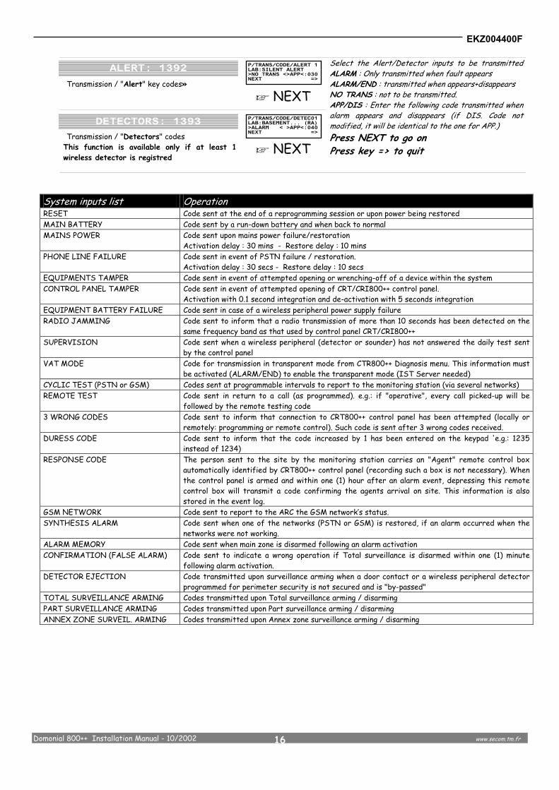
Transmission / "Alert" key codes»
e NEXT Transmission / "Detectors" codes
This function is available only if at least 1 wireless detector is registred
e NEXT
Select the Alert/Detector inputs to be transmitted ALARM : Only transmitted when fault appears ALARM/END : transmitted when appears+disappears NO TRANS : not to be transmitted. APP/DIS : Enter the following code transmitted when alarm appears and disappears (if DIS. Code not modified, it will be identical to the one for APP.) Press NEXT to go on Press key => to quit
System inputs list Operation RESET Code sent at the end of a reprogramming session or upon power being restored MAIN BATTERY Code sent by a run-down battery and when back to normal MAINS POWER Code sent upon mains power failure/restoration
Activation delay : 30 mins - Restore delay : 10 mins PHONE LINE FAILURE Code sent in event of PSTN failure / restoration.
Activation delay : 30 secs - Restore delay : 10 secs EQUIPMENTS TAMPER Code sent in event of attempted opening or wrenching-off of a device within the system CONTROL PANEL TAMPER Code sent in event of attempted opening of CRT/CRI800++ control panel.
Activation with 0.1 second integration and de-activation with 5 seconds integration EQUIPMENT BATTERY FAILURE Code sent in case of a wireless peripheral power supply failure RADIO JAMMING Code sent to inform that a radio transmission of more than 10 seconds has been detected on the
same frequency band as that used by control panel CRT/CRI800++ SUPERVISION Code sent when a wireless peripheral (detector or sounder) has not answered the daily test sent
by the control panel VAT MODE Code for transmission in transparent mode from CTR800++ Diagnosis menu. This information must
be activated (ALARM/END) to enable the transparent mode (IST Server needed) CYCLIC TEST (PSTN or GSM) Codes sent at programmable intervals to report to the monitoring station (via several networks) REMOTE TEST Code sent in return to a call (as programmed). e.g.: if "operative", every call picked-up will be
followed by the remote testing code 3 WRONG CODES Code sent to inform that connection to CRT800++ control panel has been attempted (locally or
remotely: programming or remote control). Such code is sent after 3 wrong codes received. DURESS CODE Code sent to inform that the code increased by 1 has been entered on the keypad 'e.g.: 1235
instead of 1234) RESPONSE CODE The person sent to the site by the monitoring station carries an "Agent" remote control box
automatically identified by CRT800++ control panel (recording such a box is not necessary). When the control panel is armed and within one (1) hour after an alarm event, depressing this remote control box will transmit a code confirming the agents arrival on site. This information is also stored in the event log.
GSM NETWORK Code sent to report to the ARC the GSM network’s status. SYNTHESIS ALARM Code sent when one of the networks (PSTN or GSM) is restored, if an alarm occurred when the
networks were not working. ALARM MEMORY Code sent when main zone is disarmed following an alarm activation CONFIRMATION (FALSE ALARM) Code sent to indicate a wrong operation if Total surveillance is disarmed within one (1) minute
following alarm activation. DETECTOR EJECTION Code transmitted upon surveillance arming when a door contact or a wireless peripheral detector
programmed for perimeter security is not secured and is "by-passed" TOTAL SURVEILLANCE ARMING Codes transmitted upon Total surveillance arming / disarming PART SURVEILLANCE ARMING Codes transmitted upon Part surveillance arming / disarming ANNEX ZONE SURVEIL. ARMING Codes transmitted upon Annex zone surveillance arming / disarming

EKZ004400F
Domonial 800++ Installation Manual - 10/2002 www.secom.tm.fr
17
3-10 Programming engineer code, date and time, optional GSM unit, Users codes
Access to applicable menus is as follows:
Enter code (001234 factory default values) then e1 e4 e1
Remote control and programming access codes changing.
e =>
Enter new 6-digit code using the numeric keys. Press => to go on
The display modification date & time changing. Date & time are used by the event log file for message dating
e =>
Enter new date & time using the numeric keys For the
time press " " key Press => to go on
To set the PIN code for the optional GSM Network unit
e =>
Enter the PIN code of the SIM card (often 0000, depending on provider) Press => VALID Wait for the “correct code “message Press => to go on
This display allows a 16-digit text.
e =>
Enter memo using the numeric keys. Key > for next character (16 maximum). Press => to go on
Remote DTMF code for user
e =>
Enter new 6-digit code using the numeric keys. Press => key to go on
For security reason, the installer must ask the customer to change this code This display allows user codes to be change via the CLB800 keypad.
e =>
MASTER: to change the code label (8 char. max) REPORT: Y/N for transmission Arming and disarming information to the monitoring station MODIF CLB: Y/N to allow changing code on CLB keypad (if NO is selected, this user will not be showed on the CLB800 changing codes menu) MORE: to change the code (4 numbers) Press => to go on
Functions \ Users Master 1 2 3 4 5 6 7 8 9
Label (8 characters) Y Y Y Y Y Y Y Y Y Y Supervised user (REPORT)
Y/N Y/N Y/N Y/N Y/N Y/N Y/N Y/N Y/N Y/N
Displayed on CLBX00HF for modification (MODIF CLB)
Y/N Y/N Y/N Y/N Y/N Y/N Y/N Y/N Y/N Y/N
EKZ004400F
Domonial 800++ Installation Manual - 10/2002 www.secom.tm.fr
18
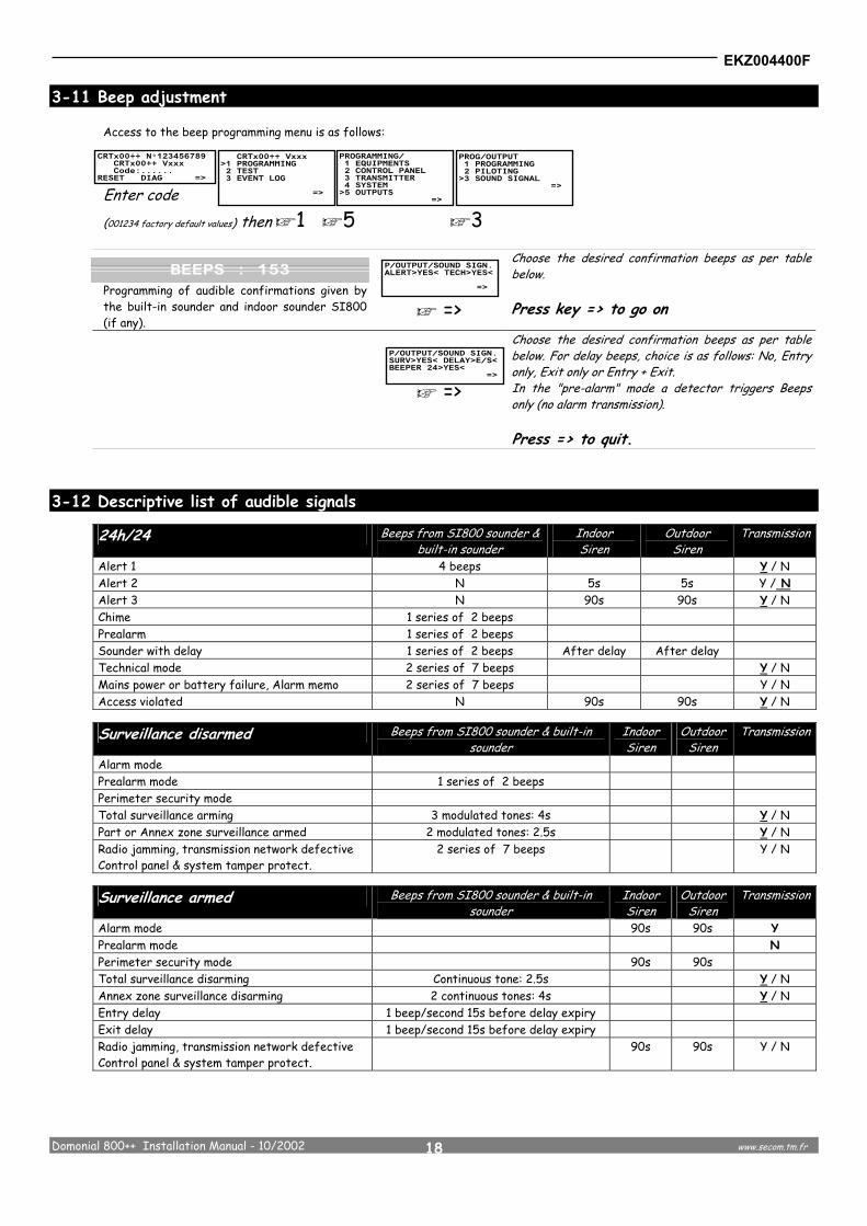
3-11 Beep adjustment Access to the beep programming menu is as follows:
Enter code (001234 factory default values) then e1 e5 e3 Programming of audible confirmations given by the built-in sounder and indoor sounder SI800 (if any).
e =>
Choose the desired confirmation beeps as per table below. Press key => to go on
e =>
Choose the desired confirmation beeps as per table below. For delay beeps, choice is as follows: No, Entry only, Exit only or Entry + Exit. In the "pre-alarm" mode a detector triggers Beeps only (no alarm transmission). Press => to quit.
3-12 Descriptive list of audible signals
24h/24 Beeps from SI800 sounder & built-in sounder
Indoor Siren
Outdoor Siren
Transmission
Alert 1 4 beeps Y / N Alert 2 N 5s 5s Y / N Alert 3 N 90s 90s Y / N Chime 1 series of 2 beeps Prealarm 1 series of 2 beeps Sounder with delay 1 series of 2 beeps After delay After delay Technical mode 2 series of 7 beeps Y / N Mains power or battery failure, Alarm memo 2 series of 7 beeps Y / N Access violated N 90s 90s Y / N
Surveillance disarmed Beeps from SI800 sounder & built-in sounder
Indoor Siren
Outdoor Siren
Transmission
Alarm mode Prealarm mode 1 series of 2 beeps Perimeter security mode Total surveillance arming 3 modulated tones: 4s Y / N Part or Annex zone surveillance armed 2 modulated tones: 2.5s Y / N Radio jamming, transmission network defective Control panel & system tamper protect.
2 series of 7 beeps Y / N
Surveillance armed Beeps from SI800 sounder & built-in sounder
Indoor Siren
Outdoor Siren
Transmission
Alarm mode 90s 90s Y Prealarm mode N Perimeter security mode 90s 90s Total surveillance disarming Continuous tone: 2.5s Y / N Annex zone surveillance disarming 2 continuous tones: 4s Y / N Entry delay 1 beep/second 15s before delay expiry Exit delay 1 beep/second 15s before delay expiry Radio jamming, transmission network defective Control panel & system tamper protect.
90s 90s Y / N

EKZ004400F
Domonial 800++ Installation Manual - 10/2002 www.secom.tm.fr
19
4 - SYSTEM TESTING
In normal service conditions, the main circuit board LED must keep flashing at the rate of 1.5 second. If it is off, the board power supply must be checked. The software version can be read from TB550 when programming is initiated.
4-1 Radio tests
Access to the radio test menu is as follows: Enter code (001234 factory default values) then e2 e1
Test the ambient radio level on the same frequency as CRT800++ and its peripherals
e =>
The ambient level must not be higher than 4 permanent boxes to ensure secure operation of the system Press => to go on.
Test peripheral’s reception level.
e =>
This menu enables the radio level to be tested and the system wireless peripherals to be positioned Press => to go on
4-2 Sounder tests
Access to the sounder test menu is as follows:
Enter code (001234 factory default values) then e2 e3 Test of the wireless and built-in sounders of the system.
e =>
Press "ON" to trigger the sounders and "OFF" to silence them. Press => to go on
4-3 Radio Receiver test
The control panel logs 500 date-stamped events. The event log readout is as follows:
Enter code (001234 factory default values) then e2 e4
e NEXT
Press keys "ON" and "OFF" to activate the radio relay. - Press => to quit.
gg0000000000
gggggg0000
p The minimum recording level to secure suitable performance is 2 boxes out of 10.
EKZ004400F
Domonial 800++ Installation Manual - 10/2002 www.secom.tm.fr
20
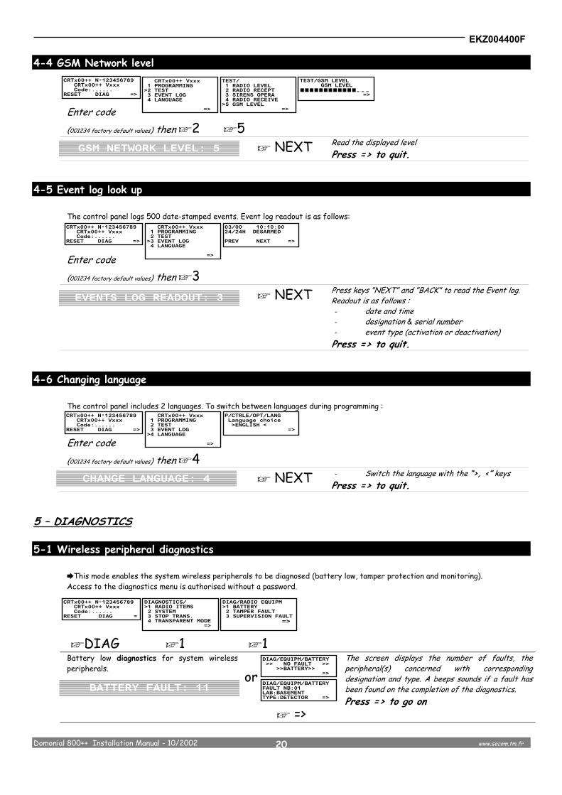
4-4 GSM Network level Enter code (001234 factory default values) then e2 e5
e NEXT Read the displayed level Press => to quit.
4-5 Event log look up
The control panel logs 500 date-stamped events. Event log readout is as follows: Enter code (001234 factory default values) then e3
e NEXT Press keys "NEXT" and "BACK" to read the Event log. Readout is as follows : - date and time - designation & serial number - event type (activation or deactivation) Press => to quit.
4-6 Changing language
The control panel includes 2 languages. To switch between languages during programming :
Enter code (001234 factory default values) then e4
e NEXT - Switch the language with the “>, <” keys Press => to quit.
5 – DIAGNOSTICS
5-1 Wireless peripheral diagnostics This mode enables the system wireless peripherals to be diagnosed (battery low, tamper protection and monitoring). Access to the diagnostics menu is authorised without a password.
eDIAG e1 e1 Battery low diagnostics for system wireless peripherals.
or
e =>
The screen displays the number of faults, the peripheral(s) concerned with corresponding designation and type. A beeps sounds if a fault has been found on the completion of the diagnostics. Press => to go on
gggggggggggg000
EKZ004400F
Domonial 800++ Installation Manual - 10/2002 www.secom.tm.fr
21
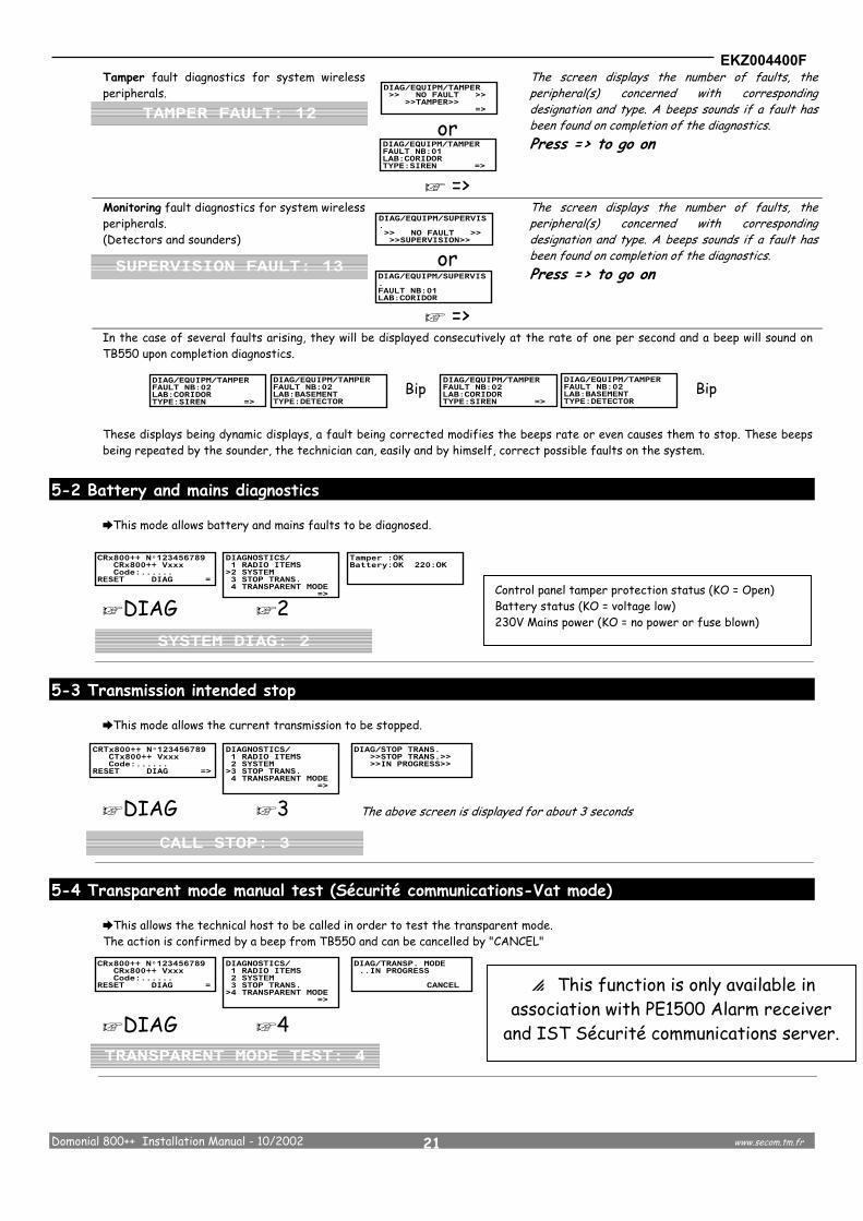
Tamper fault diagnostics for system wireless peripherals.
or
e =>
The screen displays the number of faults, the peripheral(s) concerned with corresponding designation and type. A beeps sounds if a fault has been found on completion of the diagnostics. Press => to go on
Monitoring fault diagnostics for system wireless peripherals. (Detectors and sounders)
or
e =>
The screen displays the number of faults, the peripheral(s) concerned with corresponding designation and type. A beeps sounds if a fault has been found on completion of the diagnostics. Press => to go on
In the case of several faults arising, they will be displayed consecutively at the rate of one per second and a beep will sound on TB550 upon completion diagnostics.
These displays being dynamic displays, a fault being corrected modifies the beeps rate or even causes them to stop. These beeps being repeated by the sounder, the technician can, easily and by himself, correct possible faults on the system.
5-2 Battery and mains diagnostics
This mode allows battery and mains faults to be diagnosed.
eDIAG e2
5-3 Transmission intended stop
This mode allows the current transmission to be stopped.
eDIAG e3 The above screen is displayed for about 3 seconds
5-4 Transparent mode manual test (Sécurité communications-Vat mode)
This allows the technical host to be called in order to test the transparent mode. The action is confirmed by a beep from TB550 and can be cancelled by "CANCEL"
eDIAG e4
Bip Bip
Control panel tamper protection status (KO = Open) Battery status (KO = voltage low) 230V Mains power (KO = no power or fuse blown)
p This function is only available in association with PE1500 Alarm receiver
and IST Sécurité communications server.

EKZ004400F
Domonial 800++ Installation Manual - 10/2002 www.secom.tm.fr
22
6 – OPERATION 6-1 Transmission to a DTMF telephone set
Once programmed Domonial++ can send information to a telephone set. When a call is received and the handset is picked up the identification music is played followed by a number of beeps corresponding to the triggered input. When several devices have been triggered, only the first one is indicated. After the message has been listened to an acknowledgement is made by pressing the # key . Then (on the CRI/PCI version only), if there is audio programmed, the site can be listened to remotly. The call is terminated by hanging up. If the above configuration does not exist or in the case of a decimal telephone, the message will be repeated using the programmed sequence. The identification music can be changed by means of PC software.
Mimic diagram Press key :
Ringing Pick-up Identification Beeps Acknowledge Listen (CRI) Hang-up 6-2 Using the CLI800HF optional wireless keypad
How to use the keypad
Total Arming : Press key (then enter your code : see § How to program the ON key).
Partial Arming : Press key then entre your secret code.
Disarming : Press key then entre your secret code.
Alert (panic) : Press to trigger an alert. The operation will have been pre-programmed during registration of the keypad on the system.
How to modify the codes
To modify the code Master User To modify the Service 1 code To modify the Service 2 code
User code (1234 by default)
New code
New code
Service 1 code (1234 by default)
New code
New code
Service 2 code (1234 by default)
New code
New code
How to program the ON key
To arm an alarm system, use the “On” button without entering a code. However, for improved safety, you can set the condition that requires a secret code to be entered.
To arm the system with a code : To return to the previous command mode (without a code) :
User code
(1234 by default)
User code
(1234 by default)
Music 1 or music 2
#
Type 1 (by default) Type 2 Music 1 + bip
Music 2 + bip
CRI/PCI800++ only

EKZ004400F
Domonial 800++ Installation Manual - 10/2002 www.secom.tm.fr
23
1/ Call the control panel from a DTMF telephone set
1000Hz beep for 1.5 second then 5 seconds silence (waiting for carrier)
Arpeggio.. Invitation music : "Arpeggio"
2/ Enter password. After 30 secs without a further entry the communicator hooks up
0 0 1 2 3 4 (factory default)
High-pitched … Password correct
*21 Total zone arming
*22 Part zone arming
*23 Annex zone arming
*4 Remote test
Arms and hang up after the melody
Communicator hang up and sends a remote test
Beep for 2 seconds high/low-pitched
> To enable remote control via phone, the control panel pick up mode must not be programmed to "No". (1) Please consult us for the available software version
*# Hang up
Low-pitched … Password wrong
*16 Activate Relay 1
*17 Activate Relay 2
*18 Activate Relay 3
*19 Activate Relay 4
(Optional Wireless Remote Plug or Relay)
*6 Audio
1 Speaking
0 Listening
*8 Changing Phone N°
6-3 DTMF Remote controls
#
Dial actual number
Dial new number
Confirmation by high beep
Dial new number
Confirmation by high beep
Hang up
Hang up
(1)
EKZ004400F
Domonial 800++ Installation Manual - 10/2002 www.secom.tm.fr
24
7 - TECHNICAL APPENDIXES
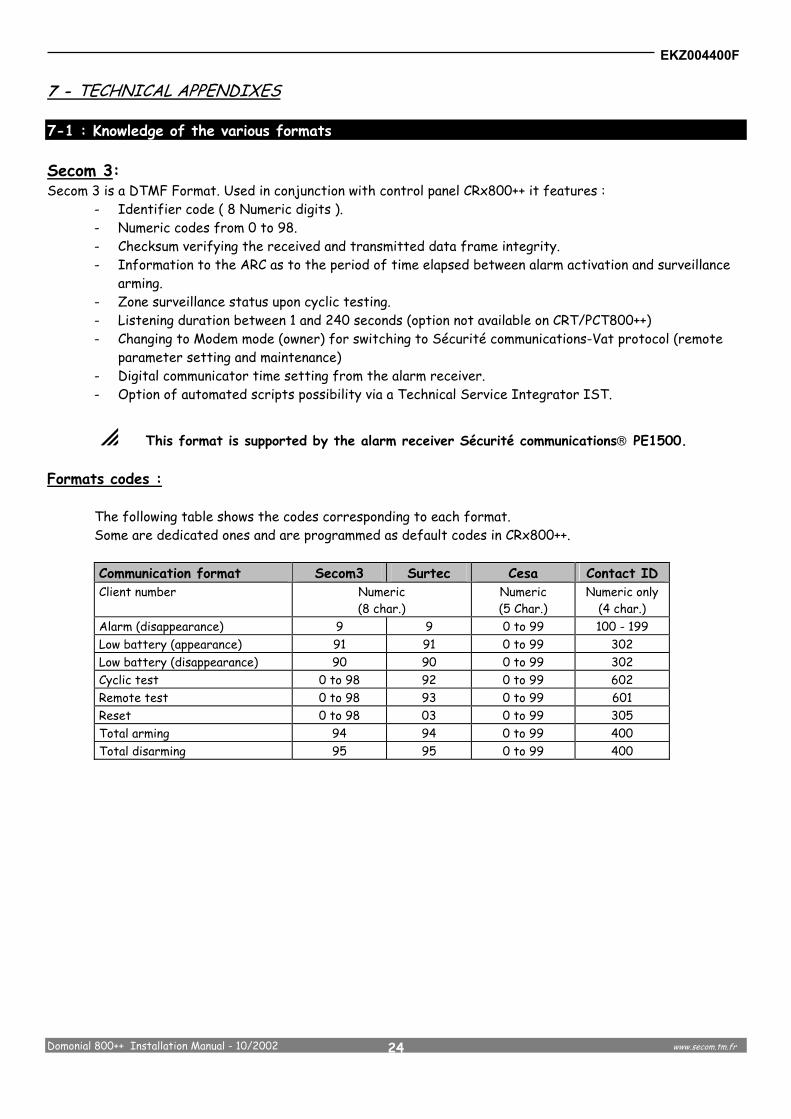
7-1 : Knowledge of the various formats Secom 3: Secom 3 is a DTMF Format. Used in conjunction with control panel CRx800++ it features :
- Identifier code ( 8 Numeric digits ). - Numeric codes from 0 to 98. - Checksum verifying the received and transmitted data frame integrity. - Information to the ARC as to the period of time elapsed between alarm activation and surveillance
arming. - Zone surveillance status upon cyclic testing. - Listening duration between 1 and 240 seconds (option not available on CRT/PCT800++) - Changing to Modem mode (owner) for switching to Sécurité communications-Vat protocol (remote
parameter setting and maintenance) - Digital communicator time setting from the alarm receiver. - Option of automated scripts possibility via a Technical Service Integrator IST.
p This format is supported by the alarm receiver Sécurité communications PE1500. Formats codes : The following table shows the codes corresponding to each format. Some are dedicated ones and are programmed as default codes in CRx800++.
Communication format Secom3 Surtec Cesa Contact ID Client number Numeric
(8 char.) Numeric (5 Char.)
Numeric only (4 char.)
Alarm (disappearance) 9 9 0 to 99 100 - 199 Low battery (appearance) 91 91 0 to 99 302 Low battery (disappearance) 90 90 0 to 99 302 Cyclic test 0 to 98 92 0 to 99 602 Remote test 0 to 98 93 0 to 99 601 Reset 0 to 98 03 0 to 99 305 Total arming 94 94 0 to 99 400 Total disarming 95 95 0 to 99 400

EKZ004400F
Domonial 800++ Installation Manual - 10/2002 www.secom.tm.fr
25
7-2 List of the associated wireless peripherals
IR800 Passive infrared motion detector Detection range ~10m Radio range ~50m on site depending on local environment Opening tamper protection and wall tamper (depending on model) Supervised : yes Power requirement: 1 battery CR123 - 3V with low battery indication transmission Battery life ~5 years
IR800PI Passive infrared motion detector pet-imune Detection range ~10m Radio range ~50m on site depending on local environment Opening tamper protection and wall tamper (depending on model) Supervised : yes Power requirement: 1 battery CR123 - 3V with low battery indication transmission Battery life ~5 years
DOD800 Door/Window detector with off-fitted contact possibility Radio range ~50m on site depending on local environment Opening and wall tamper Supervised: yes Power requirement: 1 battery CR123 - 3V with low battery indication transmission Battery life ~5 years
BVA800 Glass-break detector Detection area 360° - 7,50m Radio range ~50m on site depending on local environment Opening tamper Supervised: yes Power requirement: 1 battery SL761 - 3.6V with low battery indication transmission Battery life ~5 years
DFO800 Smoke detector Detection area ~50m² Radio range ~50m on site depending on local environment Opening tamper protection Supervised: yes Power requirement: 1 battery SL761 - 3.6V with low battery indication transmission Battery life ~5 years
WR800 Wireless Remote 1 relay output 1 detection input 1 tamper input Radio range ~50 m in the open Mains Powered by 12V= Output Status Saving by batteries CR123 Opening and wrenching tamper protection for in box model
SI800 Indoor Siren Power 85 to 115dB Radio range ~50m on site depending on local environment Opening and wrenching tamper protection Supervised: yes Power requirement: 4 batteries CR123 - 3V with low battery indication transmission Battery life ~4 years
RS800 Remote Mains Plug (DIN format) Radio range ~50 m in the open Powered by mains 1500W switched
CLB800 keypad with LCD display (10 codes + 1 duress code) Radio range ~50m on site depending on local environment Opening and wrenching tamper protection Power requirement: 1 battery – 3,6V with low battery indication transmission Battery life ~ 3 years
CSK800 Keypad with built-in proximity fob reader (10 users) Radio range ~50m on site depending on local environment Opening and wall tamper Power requirement: 1 battery CR123 - 3V with low battery indication transmission Battery life ~ 100,000 operations
CLI800 Control keypad (3 codes + 1 duress code) Radio range ~50m on site depending on local environment Opening and wrenching tamper protection Power requirement: 1 battery CR123 - 3V with low battery indication transmission Battery life ~ 100,000 operations
CLI810 Control keypad (10 users) Radio range ~50m on site depending on local environment Opening and wrenching tamper protection Power requirement: 1 battery CR123 - 3V with low battery indication transmission Battery life ~ 100,000 operations
TC804 4-buttons keyfob Radio range ~50 m in the open Power requirement 1 battery (included) Battery life ~ 150,000 operations Weight 30 grams
TC805 4-buttons keyfob / 5 functions Radio range ~50 m in the open Power requirement 1 battery (included) Battery life ~ 150,000 operations Weight 30 grams Wireless devices operating capabilities

EKZ004400F
Domonial 800++ Installation Manual - 10/2002 www.secom.tm.fr
26
8 - SPECIFICATIONS 8-1 Functional
• 4 zone surveillance (Total, Part, Annex and 24hours) • Management of wireless peripherals of the Sécurité communications 800 range • Numeric transmission format : Secom3, Cesa, Surtec, contact ID (5) • Other format : phone • Built-in siren • Built-in audio half-duplex system (CRI/PCI800++ only) • 4 phones numbers (of which one reserved for remote maintenance) + 2 phones numbers for GSM Network use • Event log for 500 events • Remote parameter feeding from PC and Domocom Modem; locally from TB500 or PC
8-2 Physical
Dimensions Height : 183mm Width : 235mm / 295mm(6) Max Depth : 50mm / 56mm(5)
Temperature (CSEI - 11- 10 Standard) Operating : 5 <-> 40°C Storage : -40 <-> 70°C
Relative humidity (CSEI - 11- 10 Standard) < 85% Weight (with battery) 1280 g (2822 lb)
8-3 Electrical
Power requirement typique (Ut) : 230V~ 50Hz, fused (200mA) Battery Type :
Fault : 4V 3,5Ah max.
appear : 3,5 V disappear : 4 V
Typical consumption (Ut) Normal : Calling :
25 mA 85 mA
8-4 radio
Radio frequency FM narrow band 868,25MHz Number of channels Detection (IR, DO …)
Control keypad Keyfob Other bi-directionnal peripherals (siren, remote mains plug, wireless relay…)
20 2CLI + 2CLB 4 (+ 1 response) 4 (including the number of CLB’s)
Monitoring Detectors and sirens Once per 4 h Radio jamming detection Detection of a 868.25Mhz transmission
for more than 10s over a period of 20s Note: This product is in compliance with the applicable provisions of R&TTE. This equipment can be connected anywhere to the Pan-European PSTN. However, as there are some differences in the PSTN from a country to another, this compliance is not an inherent absolute guarantee of optimal performance irrespective of the connection point to the Pan-European PSTN. Should any problem arise, contact your dealer first. The connection to the mains supply and phone line must be made in conformity with the local authority’s rules and regulation.
5 For Contact ID, the client number is only on 4 numeric characters (not hexa) ; others formats : please, consult us. 6 Depending on cover model.
----
----
----
----
----
----
----
For
pro
duct
and
use
r in
tere
st, t
he s
peci
fica
tion
s m
ay b
e su
bjec
t to
cha
nge
with
out
noti
ce --
----
----
----
----
----
----
----
----
----
----
----
----
----

EKZ004400F
Domonial 800++ Installation Manual - 10/2002 www.secom.tm.fr
27
9 – CONFORMITY DECLARATION

EKZ004400F
Domonial 800++ Installation Manual - 10/2002 www.secom.tm.fr
28
A
ADSL 10 Alert 13, 21, 24, 29
B
Battery4, 10, 11, 21, 24, 27, 28, 32, 33, 34, 35 Beeps 13, 14, 16, 24, 25, 28 Bistable 17 Built-in sounder 14, 15, 24, 26
C
CAB550PC 11 Cesa 7, 19, 32, 35 Chime 13, 24 CLB800 23, 35 Client code 19 Contact ID 7, 32, 35
D
Date & time 23 Delay 5, 15, 16, 18, 21, 24, 25 Deleting 3, 15 Diagnosis 27, 28 Diagnostics 27, 28, 28 Dialing prefixe 19 DTMF 3, 5, 7, 17, 23, 29, 31, 32 Duress code 21
E
Eavesdropping 17 Event log 4, 5, 21, 23, 26
F
Flashlight 17 Format 16, 19, 32, 33, 35
G
GSM Network 3, 5, 7, 19, 21, 23, 27, 35
H
Hybrid 5
J
Jamming 21
K
Keyfob 13, 15, 34 Keypad 3, 5, 13, 16, 21, 23, 29, 33, 35
L
Language 3, 27 LED 3, 11, 17, 26 Level 3, 9, 15, 26, 27 Listening time 19
M
Mains power 21 Master 23 Memo 23, 24
N
Number of rings 19
P
PE1500 Receiver 32 Periodic test 19 Phone numbers 19 PIN Code 23
Prealarm 13, 24 PSTN Network 4, 5, 6, 7, 17, 19, 21, 36
R
Recording 3, 13 Remote 5, 15, 16, 19, 23, 31, 32, 33, 35 Remote access 19 Reset 21 Response 21
S
Secom 3 32 Serial port 11, 13, 16, 27 Sounder 3, 6, 24, 26 Status 17 Stocko 10 Supervised 5, 23, 33 Supervision 21 Surtec 7, 32, 35 Synthesis Alarm 21
T
Tamper 18, 28 TB550 3, 4, 12, 26, 28 Telephone 3, 5, 7, 8, 10, 18, 19, 29 Teleruptor 17 Tests 3, 9, 26 Transparent mode 21, 28
U
Users 5, 33
V
VAT Mode 21

EKZ004400F
Domonial 800++ Installation Manual - 10/2002 www.secom.tm.fr
29

EKZ004400F
Domonial 800++ Installation Manual - 10/2002 www.secom.tm.fr
30

EKZ004400F
Domonial 800++ Installation Manual - 10/2002 www.secom.tm.fr
31
Securite Communications - Registered Office and Clients Services Route des Dolines - BP 41
06901 SOPHIA-ANTIPOLIS Cedex FRANCE
Tél : (33) 492 942 950 - Fax : (33) 492 942 960 Web : http://www.secom.tm.fr E.mail : [email protected]