Embed Size (px)
Citation preview

MC1190A16January 1996
ULTRAFLO® Dead End Fill SystemInstal lat ion Manual
instal lat ion • wiring diagrams • parts l ist

ULTRAFLO Dead End Fill System Installation Manual • Page 2

ULTRAFLO Dead End Fill System Installation Manual • Page 3
(CE-mark serial number)
Support InformationThe ULTRAFLO Dead End Fill System is designed to convey poultryfeed types. Using this equipment for any other purpose or in a way notwithin the operating recommendations specified in this manual willvoid the warranty and may cause personal injury and/or death.
This manual is designed to provide comprehensive planning, installa-tion, wiring, operation, and parts listing information. The Table of Contents provides a convenient overview of the information in this manual. The Table of Contents also specifies which pages contain information for the sales personal, installer, and consumer (end user).
IMPORTANT: CE stands for certified Europe. It is a standard whichequipment must meet or exceed in order to be sold in Europe. CE pro-vides a benchmark for safety and manufacturing issues. CE is re-quired only on equipment sold in Europe.
Chore-Time Equipment recognizes CE Mark and pursues compliancein all applicable products. Please fill in the CE-Mark serial number inthe blank space provided for future reference.
Please include the name and address of your Chore-Time Distributorand installer.
Please fill in the following information about your ULTRAFLO Dead End Fill System. Keep this manual in a clean, dry place for future reference.
Distributor’s Name
Distributor’s Address
Distributor’s Phone Date of Purchase
Installer’s Name
Installer’s Address
Installer’s Phone Date of Installation
System Specifications
Feed Delivery System Supplying

ULTRAFLO Dead End Fill System Installation Manual • Page 4
Table of ContentsTopic Page User*
Support Information ...................................................................................................... 3 C, D
Safety Information ........................................................................................................ 5 - 6 C, I
General & Planning Information ................................................................................... 6 C, I
Dead End Fill System Installation................................................................................. 7 - 10 IFeed Manifold Installation ...................................................................................................7 IFill System Installation (Inside Portion) ...............................................................................7 - 8 IDrop Tube Installation ........................................................................................................8 ISwitch Installation ...............................................................................................................8 - 9 IFill System Installation (Outside Portion) ............................................................................10 I
System Wiring Diagrams.............................................................................................. 11 - 14 I
Feed Manifold Part Numbers ....................................................................................... 15 C, D
*Legend: C = Customer (end user), D = Distributor (sales), I = Installer of equipment
Related Instruct ion Manuals Inst . No.
Two Motor Tandem System Manual (Model 90) MA524
Two Motor Tandem System Manual (Model 108) MA1101
Model 55, 75, 90, & HMC FLEX-AUGER Fi l l System Manual MA1000
Model 108 FLEX-AUGER Fi l l System Manual MA1032
Dual Model 90 Contro l Uni t MA1277
Dual Model 108 Contro l Uni t MA1064
Model 90, 108, & Dual 90 Feed Screener Manual MC1033
ULTRAFLO Feeding System Manual MC656
Note: Some of the inst ruct ions l is ted above are avai lab le in var ious languages. Contact your CHORE-TIME Dis t r ibutor for addi t ional manuals .

ULTRAFLO Dead End Fill System Installation Manual • Page 5
Safety InformationCaution, Warning and Danger Decals have been placed on the equipment to warn of potentially dangerous situ-ations. Care should be taken to keep this information intact and easy to read at all times. Replace missing or dam-aged safety signs.
Using the equipment for purposes other than specified in this manual may cause personal injury or damage to theequipment.
Safety–Alert SymbolThis is a safety–alert symbol. When you see this symbol on your equipment, bealert to the potential for personal injury. Chore-Time equipment is designed tobe installed and operated as safely as possible...however, hazards do exist.
DANGER
WARNING
CAUTION
Signal WordsSignal words are used in conjunction with the safety–alert symbol to identify the severity of the warning.
DANGER ........... indicates an imminently hazardous situation which, if not avoided, WILL result in death or serious injury.
WARNING ......... indicates a potentially hazardous situation which, if not avoided, COULD result in death or serious injury.
CAUTION .......... indicates a hazardous situation which, if not avoided, MAY result in minor or moderate injury.
DANGER: MOVING AUGERThis decal is placed on the Clean-Out Cover of theFLEX-AUGER Control Unit.
Severe personal injury will result, if the electrical poweris not disconnected, prior to servicing the equipment.
DANGER: ELECTRICAL HAZARDDisconnect electrical power before inspecting or servicing equipmentunless maintenance instructions specifically state otherwise.
Ground all electrical equipment for safety.
All electrical wiring must be done by a qualified electrician in accordancewith local and national electric codes.
Ground all non-current carrying metal parts to guard against electricalshock.
With the exception of motor overload protection, electrical disconnectsand over current protection are not supplied with the equipment.
ULTRAFLO Dead End Fill System Installation Manual • Page 6
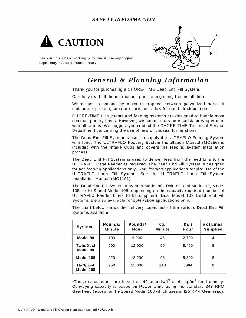
SAFETY INFORMATION
Use caution when working with the Auger--springingauger may cause personal injury.
CAUTION
General & Planning InformationThank you for purchasing a CHORE-TIME Dead End Fill System.
Carefully read all the instructions prior to beginning the installation.
White rust is caused by moisture trapped between galvanized parts. Ifmoisture is present, separate parts and allow for good air circulation.
CHORE-TIME fill systems and feeding systems are designed to handle mostcommon poultry feeds. However, we cannot guarantee satisfactory operationwith all rations. We suggest you contact the CHORE-TIME Technical ServiceDepartment concerning the use of new or unusual formulations.
The Dead End Fill System is used to supply the ULTRAFLO Feeding Systemwith feed. The ULTRAFLO Feeding System Installation Manual (MC656) isincluded with the Intake Cups and covers the feeding system installationprocess.
The Dead End Fill System is used to deliver feed from the feed bins to theULTRAFLO Cage Feeder as required. The Dead End Fill System is designedfor tier feeding applications only. Row feeding applications require use of theULTRAFLO Loop Fill System. See the ULTRAFLO Loop Fill SystemInstallation Manual (MC1191).
The Dead End Fill System may be a Model 90, Twin or Dual Model 90, Model108, or Hi-Speed Model 108, depending on the capacity required (number ofULTRAFLO Feeder Lines to be supplied). Dual Model 108 Dead End FillSystems are also available for split-ration applications only.
The chart below shows the delivery capacities of the various Dead End FillSystems available.
*These calculations are based on 40 pounds/ft3 or 64 kg/m3 feed density.Conveying capacity is based on Power Units using the standard 348 RPMGearhead (except on Hi-Speed Model 108 which uses a 425 RPM Gearhead).
SystemsPounds/Minute
Pounds/Hour
Kg./Minute
Kg./Hour
# of Lines Supplied
Model 90 100 6,000 45 2,700 4
Twin/DualModel 90
200 12,000 90 5,400 8
Model 108 220 13,200 98 5,800 8
Hi-SpeedModel 108
250 15,000 113 6804 8
ULTRAFLO Dead End Fill System Installation Manual • Page 7
Dead End Fil l System Instal lat ion
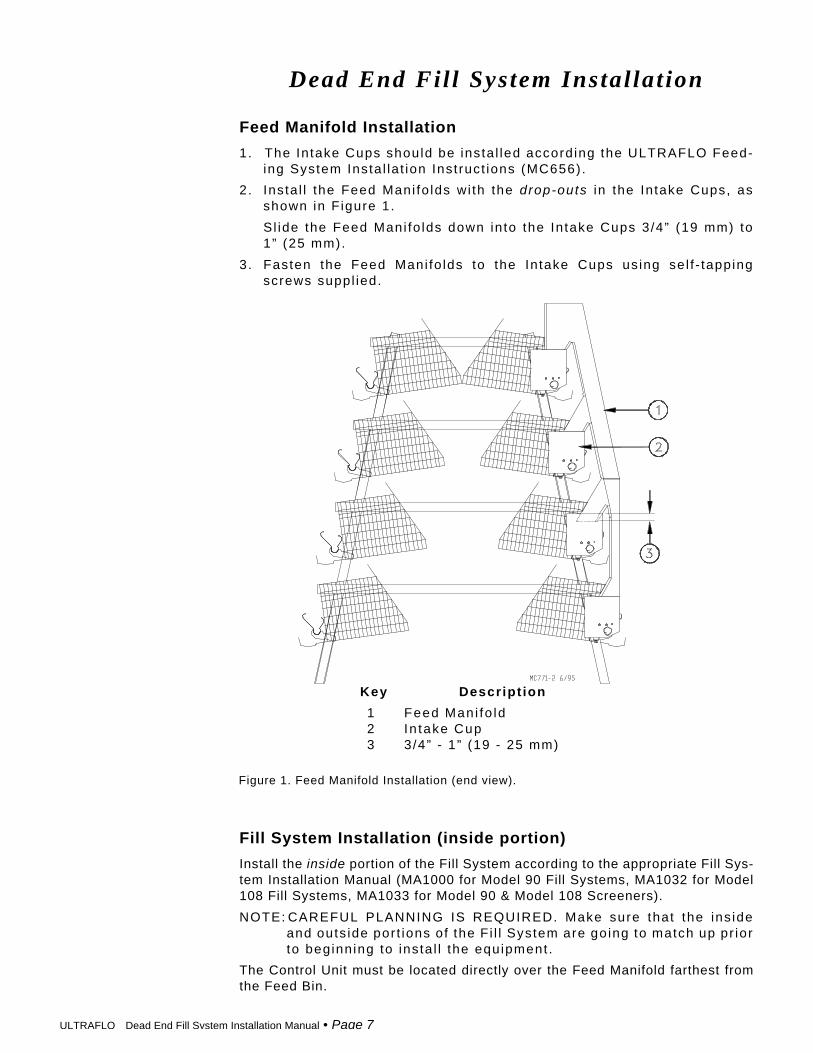
Feed Manifold Installation
1. The In take Cups should be insta l led accord ing the ULTRAFLO Feed-ing System Insta l la t ion Inst ruct ions (MC656).
2. Insta l l the Feed Mani fo lds wi th the drop-outs in the Intake Cups, asshown in F igure 1.
Sl ide the Feed Mani fo lds down in to the In take Cups 3/4” (19 mm) to1” (25 mm).
3. Fasten the Feed Mani fo lds to the In take Cups us ing se l f - tappingscrews suppl ied.
Fill System Installation (inside portion)
Install the inside portion of the Fill System according to the appropriate Fill Sys-tem Installation Manual (MA1000 for Model 90 Fill Systems, MA1032 for Model108 Fill Systems, MA1033 for Model 90 & Model 108 Screeners).
NOTE: CAREFUL PLANNING IS REQUIRED. Make sure that the ins ideand outs ide por t ions of the F i l l System are going to match up pr iorto beginning to insta l l the equipment .
The Control Unit must be located directly over the Feed Manifold farthest fromthe Feed Bin.
Figure 1. Feed Manifold Installation (end view).
Key Descript ion
1 Feed Mani fo ld2 In take Cup3 3/4” - 1” (19 - 25 mm)

ULTRAFLO Dead End Fill System Installation Manual • Page 8
An Outlet Drop must be located directly above each Feed Manifold. If possibledo not install an Outlet Drop on or just before an elbow. If the Outlet Drop MUSTbe installed on or just before an elbow, reduce the size of the outlet hole to pro-vide some feed bypass to cushion the auger.
The Fill System should be suspended approximately 12” (31 cm) above the FeedManifolds.
Drop Tube Installation
Cut the Drop Tubes to length and insert into the bottom of the Outlet Drop. SeeFigure 2.
The Drop Tubes should extend down into the top of the Feed Manifolds approx-imately 2” (50 mm), as specified in Figure 2.
Model 90, Twin 90, & Dual Model 90: Secure the Drop Tube to the Outlet Dropusing the Hose Clamp supplied.
Model 108: Secure the Drop Tube to the Outlet Drop using the self-tappingscrews supplied.
Figure 2. Drop Tube Installation–Model 108 Outlet Drop shown (side view).
Key Descript ion
1 Out le t Drop (Model 108 shown)2 Sel f -Tapping Screw (Note: Model 90
uses a Hose Clamp in p lace of Se l f -Tapping Screw.)
3 Drop Tube4 Feed Mani fo ld5 Intake Cup
Switch Installation
The Proximity Level Switch Assembly is designed to provide reliable feed sens-ing in confinement poultry applications.
The ULTRAFLO version of the Proximity Level Switch does not include anyswitching relays or contactors and is intended to switch only control circuitry (notmotor current).

ULTRAFLO Dead End Fill System Installation Manual • Page 9
Figure 3. Proximity Level Switch Installation (side view).
Key Descript ion
1 Dead End Fi l l System Contro l Uni t2 Prox imi ty Swi tch3 Contro l Uni t Drop Assembly4 Drop Tube5 Hose Clamp
The Switch is used to start and stop the Fill System during a feeding cycle.
Figure 3 shows a Proximity Level Switch installed. Refer to the Installation In-structions (MA1193) shipped with the Proximity Level Switch for detailed instal-lation and wiring information.

ULTRAFLO Dead End Fill System Installation Manual • Page 10
Fill System Installation (outside portion)
Install the outside portion of the Fill System according to the appropriate FillSystem Installation Manual (MA1000 for Model 90, MA1032 for Model 108). SeeFigure 4.
If a Feed Screener is to be used, refer to the Feed Screener Installation Manual(MC1033) for planning and installation information.
NOTE: CAREFUL PLANNING IS REQUIRED. Make sure that the ins ideand outs ide por t ions of the F i l l System are going to match up pr iorto beginning to insta l l the equipment .
If it is necessary to cut an elbow, refer to Figure 5. Always measure along theoutside radius of the elbow when determining cut location. Use an abrasivecut-off saw to cut the hardened steel elbows.
.
Dimension ° Radius Model 90 Model 108
1 15° Elbow 15.8” (40.1 cm) 16.3” (41.4 cm)
2 22-1/2° Elbow 23.7” (60.2 cm) 24.4” (62 cm)
3 30° Elbow 31.6” (80.2 cm) 32.5” (82.6 cm)
Figure 5. Cutting the Elbow (side view).
Figure 4. Fill System Installation--outside portion (side view).

ULT
RA
FLO
D
ead End F
ill System
Installation Manual • P
age 11
Dead End Fil l System Wiring Diagram(Single Phase , w/o s tarters )
To be used wi th a l l sys tems except Model 108 High Capaci ty Two Motor Tandem Sys tems.

ULT
RA
FLO
D
ead End F
ill System
Installation Manual • P
age 12
To be used wi th Model 108 High Capaci ty Two Motor Tandem Sys tems.
Dead End Fil l System Wiring Diagram(Single Phase, w/o s tarters)

ULT
RA
FLO
D
ead End F
ill System
Installation Manual • P
age 13
Dead End Fil l System Wiring Diagram(Single Phase, w/ s tarters)

ULT
RA
FLO
D
ead End F
ill System
Installation Manual • P
age 14
Dead End Fil l System Wiring Diagram(Three Phase, w/ s tar ters)

ULTRAFLO Dead End Fill System Installation Manual • Page 15
Item Description Tiers Part No.
1 Feed Manifold
DURA-CAGE 3 24850
DURA-CAGE 4 24795
DURA-CAGE 5 28570
DURA-TRIM DBS 4 35194
DURA-TRIM DBS 5 36777
DURAKO 4 30780
DURA-STEP 2 25530
DURA II 3 27246
Brood-Grow Curtain Back 4 24463
Brood-Grow Stacked 2 25357
Brood-Grow Stacked 3 24870
Brood-Grow Stacked 4 24467
Brood-Grow 2+2 (14”) 4 24509
Brood-Grow 2+2 (15”) 4 26028
Brood-Grow DBS 4 25781
Brood-Grow ST 2 25807
Feed Manifold Part Numbers

ULTRAFLO Dead End Fill System Installation Manual • Page 16
Contact your nearby Chore-Time distributor or representative for additional parts and information.Chore-Time Equipment, A Division of CTB, Inc.
P.O. Box 2000, Milford, Indiana 46542-2000 U.S.A.Phone: 219-658-4101
Printed in the U.S.A.
Made to work.
Built to last.™
THANK-YOU for purchasing a Chore-Time Dead End Fil l System.