Embed Size (px)
Citation preview

Installation

Indoor Unit InstallationTypical Installation
Indoor Unit InstallationInstallation Location
Indoor Unit
Adequate Support!Building structure must be adequate to support the weight of the unit. Failure to ensure adequate structural support could result in unit falling from its location which could result in death, serious injury, or equipment or property only damage.1.Avoid locating the indoor unit where the return and/or supply air may be obstructed.2.Select a location where it is easy to drain the condensing water and connect to the outdoor unit.3.Keep the indoor unit far away from heat sources, vapor and flammable gas.4.Be sure that the installation of the indoor unit conforms to the installation dimension diagram.5.Be sure to leave enough space to allow access for routine maintenance.6.Install in a location where the unit is more than 3 feet away from other electric appliances such as television, audio de- vices etc.7.Select location where air filters can be easily removed.
Positioning for mounting concealed (ducted) unit
Step 1
Indoor Unit Installation
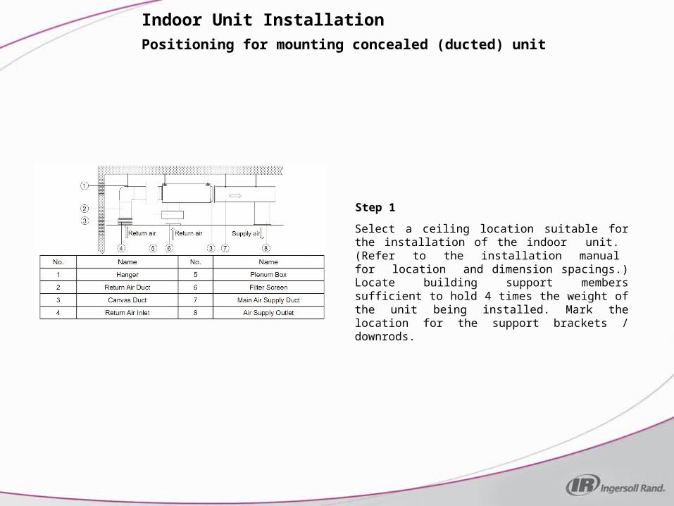
Select a ceiling location suitable for the installation of the indoor unit. (Refer to the installation manual for location and dimension spacings.) Locate building support members sufficient to hold 4 times the weight of the unit being installed. Mark the location for the support brackets / downrods.

Positioning for mounting concealed (ducted) unit
Step 2
Indoor Unit Installation
Mount the support brackets, downrods and nuts. (Field supplied.) Double-nut the top of each bracket. Be sure that the brackets / downrods have been fixed firmly enough to withstand 4 times the weight of the unit, furthermore, the weight should be evenly shared by each downrod. Install the nuts and washers on the lower ends of the downrods with enough spacing to allow the concealed (ducted) unit brackets to slide between the sets of washers. Double-nut the bottom nuts.

Installing concealed (ducted) unit
Step 1
Indoor Unit Installation
Raise the concealed (ducted) unit into position, placing the downrods in the bracket slots of the concealed (ducted) unit. Hand tighten the nuts so that the downrods will not come loose from the brackets.
Installing concealed (ducted) unit
Step 2
Indoor Unit Installation
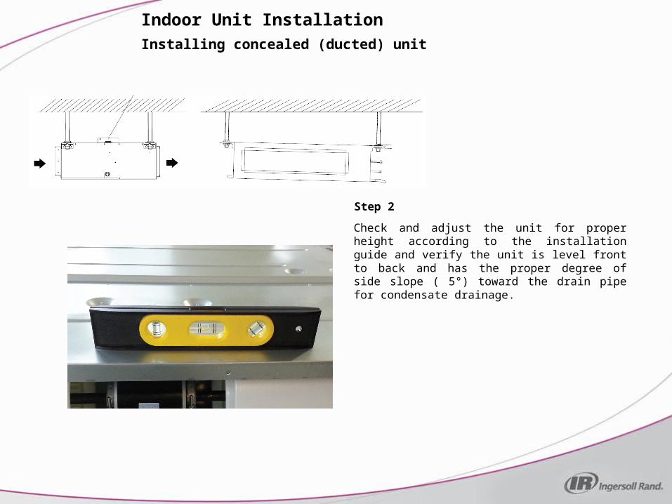
Check and adjust the unit for proper height according to the installation guide and verify the unit is level front to back and has the proper degree of side slope ( 5°) toward the drain pipe for condensate drainage.

Installing concealed (ducted) unit
Step 3
Indoor Unit Installation
Tighten all nuts on the downrods. Make sure to lock the double-nuts together at all 8 locations on the downrods.

Drilling the hole in the wall to install the piping
Step 1
Indoor Unit Installation
Find the location on the exterior wall where the piping and wiring will exit the building. Drill a 2 ½” diameter hole at a slight downward angle from the inside wall towards the outdoor wall so that the outside hole is a ¼” lower than the hole on the inside.
Drilling the hole in the wall to install the piping
Step 2
Indoor Unit Installation
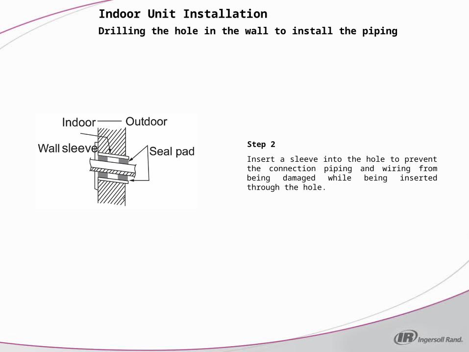
Insert a sleeve into the hole to prevent the connection piping and wiring from being damaged while being inserted through the hole.

Drilling the hole in the wall to install the piping
Step 3
Indoor Unit Installation
Pass the piping and wires through the hole using caution to ensure tubing, wiring and insulation is not kinked or damaged. Insulate the piping hole both inside and out after the piping connections have been completed at the indoor and outdoor units. Note: Image for illustration purposes only. The entire drain line tubing must be wrapped to prevent moisture from cool condensate coming in contact with and damaging the ceiling or wall.
Installing the water drain pipe
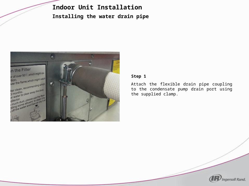
Step 1
Indoor Unit Installation
Attach the flexible drain pipe coupling to the condensate pump drain port using the supplied clamp.
Installing the water drain pipe
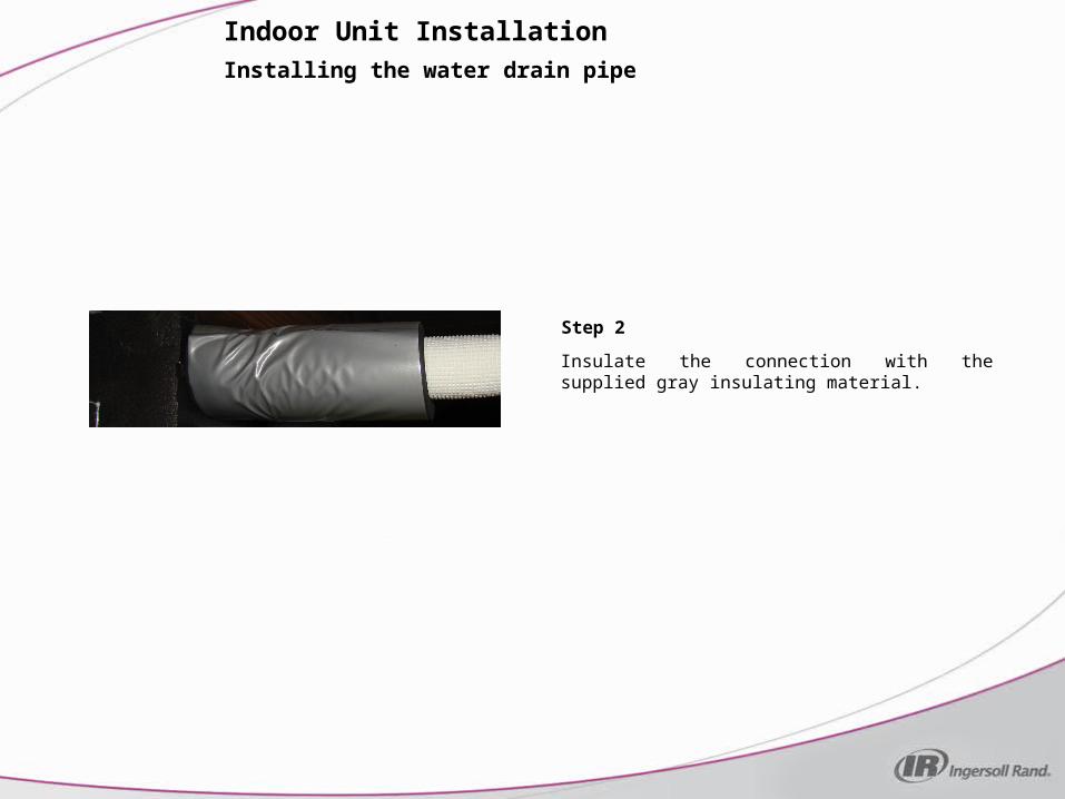
Step 2
Indoor Unit Installation
Insulate the connection with the supplied gray insulating material.

Installing the water drain pipe
Step 3
Indoor Unit Installation
Attach the condensate drain pipe to the flexible drain pipe coupling. The diameter of the condensate drain pipe should be equal to or larger than the flexible drain pipe coupling. Support the drain pipe to avoid drooping or sagging of the line. Support the pipe every 39.4 - 59 inches as needed.

Installing the water drain pipe
Step 4
Indoor Unit Installation
Should the pipe slope between the concealed (ducted) unit and the wall exit hole point be insufficient, the pipe may be raised to allow for proper drainage. The raised pipe height should be less than 33.5 inches. The drain pipe should have a pitch angle of 1°~2° for proper drainage. If the lift pipe and the unit form a right angle, the height of the lift pipe must be less than 31.5 inches.
Installing the water drain pipe
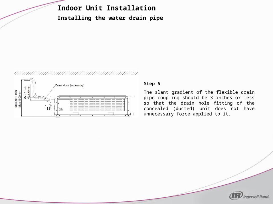
Step 5
Indoor Unit Installation
The slant gradient of the flexible drain pipe coupling should be 3 inches or less so that the drain hole fitting of the concealed (ducted) unit does not have unnecessary force applied to it.
Installing the water drain pipe
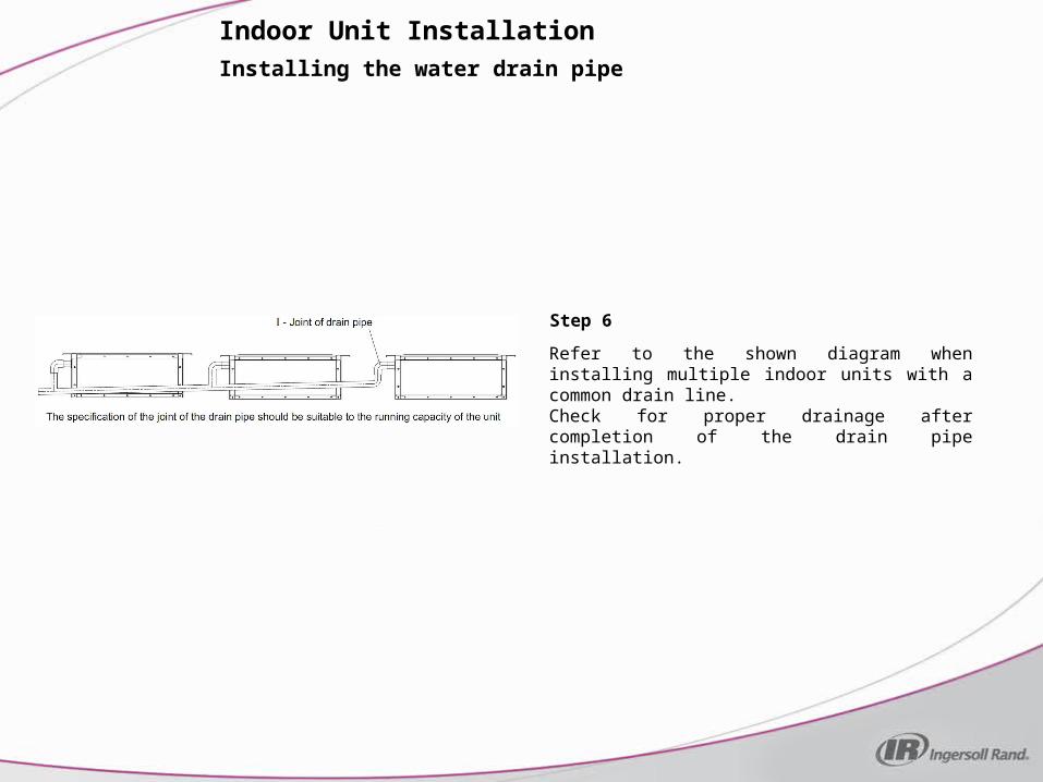
Step 6
Indoor Unit Installation
Refer to the shown diagram when installing multiple indoor units with a common drain line.Check for proper drainage after completion of the drain pipe installation.

Installing the connection pipes
Step 1
Indoor Unit Installation
A flaring kit may be necessary forthe installation of the lineset.

Installing the connection pipes
Indoor Unit Installation
Align the center of the piping flare with the relevant fitting. Screw in the flare nuts by hand and then tighten the nuts with a spanner and torque wrench. Refer to the chart for proper torque.
Note: First connect the connection pipe to the indoor unit and then to the outdoor unit. Pay attention to the pipe bending. Be sure to not damage the connection pipe. To avoid leakage be sure not to over-tighten the joint nut.Note: Refrigerant lines should be separately insulated.Once the piping has been connected to the outdoor unit and a leak test has been performed, slide the insulation over the joints to completely insulate the connections.

Installing the indoor unit wiring
Step 1
Indoor Unit Installation
Remove the two screws and cover plate, revealing the main PC board and terminal block.

Installing the indoor unit wiring
Step 2
Indoor Unit Installation
The concealed (ducted) unit uses a wired remote. Feed one end of the remote’s wire into the electric box through the wiring grommet located on the bottom of the enclosure. Plug the wire into connector C9.
Note: In addition to the outdoor breaker/fuse disconnect, a breaker or fuse is required for each indoor unit. The installation must be done in accordance with National, State, and/or local codes.
Installing the indoor unit wiring
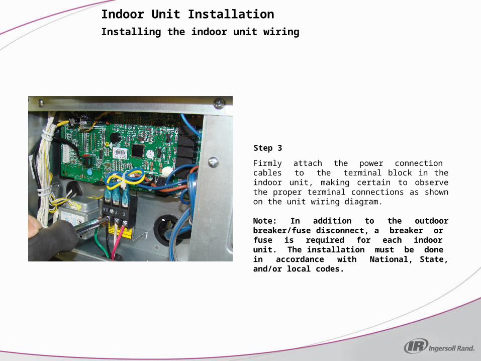
Step 3
Indoor Unit Installation
Firmly attach the power connection cables to the terminal block in the indoor unit, making certain to observe the proper terminal connections as shown on the unit wiring diagram.
Note: In addition to the outdoor breaker/fuse disconnect, a breaker or fuse is required for each indoor unit. The installation must be done in accordance with National, State, and/or local codes.

Installing the indoor unit wiring
Step 4
Indoor Unit Installation
Reattach the cover plate to the electric box.
Installing ductwork
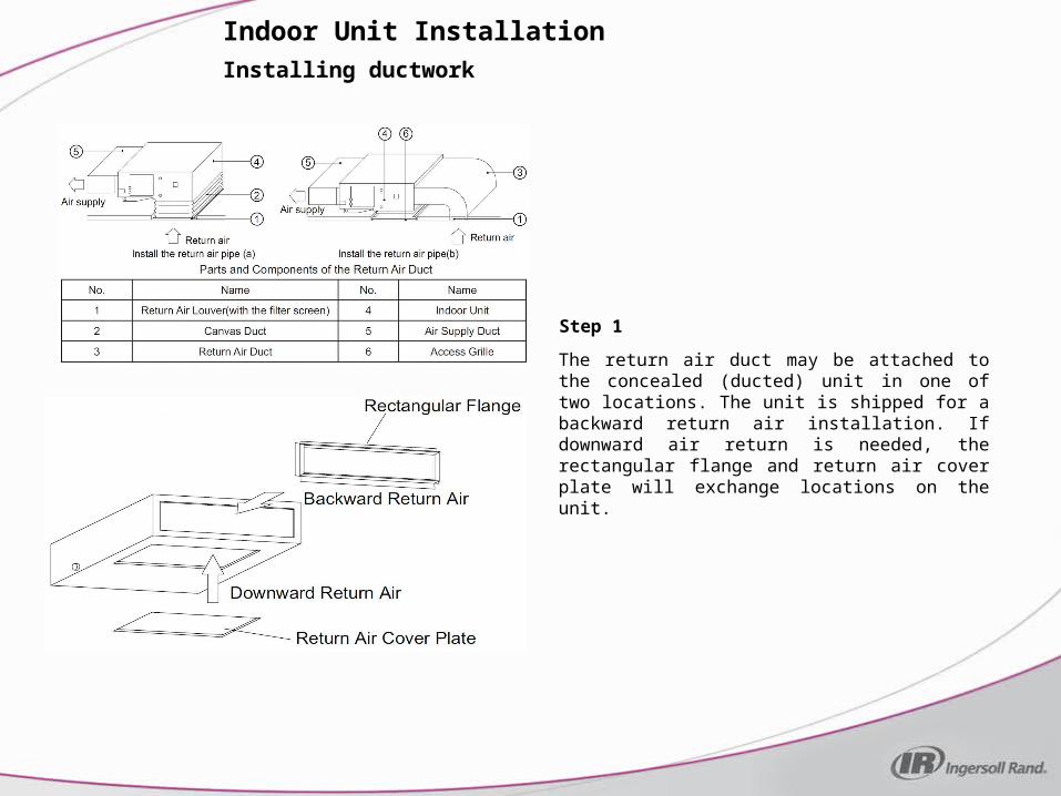
Step 1
Indoor Unit Installation
The return air duct may be attached to the concealed (ducted) unit in one of two locations. The unit is shipped for a backward return air installation. If downward air return is needed, the rectangular flange and return air cover plate will exchange locations on the unit.

Installing ductwork
Step 2
Indoor Unit Installation
The total combined duct length (return & supply) for the concealed (ducted) installation is 3.3 ft. Installation examples are shown above for both rectangular and round ductwork. Refer to the installation manual for further information.