Embed Size (px)
Citation preview
\\Op\Clients\APWA\2300\Division V Table of Contents.wpd
DIVISION VDESIGN CRITERIA
SECTION 5300 INCIDENTAL CONSTRUCTION
Approved and Adopted this 18th day of December, 2002
Kansas City Metropolitan Chapterof the American Public Works Association
Table of Contents
Section Title Page No.
5301 GENERAL5301.1 Introduction . . . . . . . . . . . . . . . . . . . . . . . . . . . . . . . . . . . . . . . . . . . . . . . . . . . . . . 53-15301.2 Definitions . . . . . . . . . . . . . . . . . . . . . . . . . . . . . . . . . . . . . . . . . . . . . . . . . . . . . . . 53-15301.3 Abbreviations . . . . . . . . . . . . . . . . . . . . . . . . . . . . . . . . . . . . . . . . . . . . . . . . . . . . . 53-15301.4 Governing Specifications . . . . . . . . . . . . . . . . . . . . . . . . . . . . . . . . . . . . . . . . . . . . 53-2
5302 LOCAL BICYCLE FACILITY DESIGN GUIDANCE5302.1 Foreword . . . . . . . . . . . . . . . . . . . . . . . . . . . . . . . . . . . . . . . . . . . . . . . . . . . . . . . . . . . 15302.2 Definitions Relating to Bicycles . . . . . . . . . . . . . . . . . . . . . . . . . . . . . . . . . . . . . . . . . 25302.3 Mitigating Hazards to Bicycle Travel . . . . . . . . . . . . . . . . . . . . . . . . . . . . . . . . . . . . . 55302.4 Types of Bicycle Facilities . . . . . . . . . . . . . . . . . . . . . . . . . . . . . . . . . . . . . . . . . . . . . 115302.5 Designating On-Road Bikeways . . . . . . . . . . . . . . . . . . . . . . . . . . . . . . . . . . . . . . . . 165302.6 Providing Designated Off-Road Bicycle Facilities . . . . . . . . . . . . . . . . . . . . . . . . . . 235302.7 Special Design Treatments . . . . . . . . . . . . . . . . . . . . . . . . . . . . . . . . . . . . . . . . . . . . . 265302.8 Bikeway Signing and Marking . . . . . . . . . . . . . . . . . . . . . . . . . . . . . . . . . . . . . . . . . . 345302.9 Bicycle Parking . . . . . . . . . . . . . . . . . . . . . . . . . . . . . . . . . . . . . . . . . . . . . . . . . . . . . 365302.10 Appendix A: Key Reference Documents . . . . . . . . . . . . . . . . . . . . . . . . . . . . . . . . . . 405302.11 Appendix B: Quick Reference Guide . . . . . . . . . . . . . . . . . . . . . . . . . . . . . . . . . . . . 415302.12 Appendix C: Bicycle Facility Selection Guide . . . . . . . . . . . . . . . . . . . . . . . . . . . . . 445302.13 Appendix D: Bikeway Facility Cross-Section . . . . . . . . . . . . . . . . . . . . . . . . . . . . . . 465302.14 Appendix E: Miscellaneous Local Examples . . . . . . . . . . . . . . . . . . . . . . . . . . . . . . 47

53-1
DIVISION VDESIGN CRITERIA
SECTION 5300 INCIDENTAL CONSTRUCTION
SECTION 5301 GENERAL
5301.1 Introduction: The purpose of this criteria is to provide uniform procedures for designing and checking the design of bicycle facilities in the Kansas City Metropolitan area. Specific criteriahave been developed and are applicable to the types of conditions ordinarily encountered in localurban and suburban areas. Other special situations may be encountered that require added criteriaor more complex design than included herein.
In addition to this criteria, bicycle facilities shall be designed to conform to applicable codes,regulations, and ordinances as established by the local governing agency. Bicycle facilities shallbe designed in accordance with the classifications determined by the local governing agencies andshall conform to APWA Standard Drawing Typical Sections, unless otherwise approved. Plansfor said improvements shall be submitted to the local governing agency for approval and shallinclude all information as may be required or described hereinafter.
5301.2 Definitions:
A. City Engineer: The term City Engineer, as used in this criteria, shall represent the state, county,city, or other governmental body's representative responsible for technical decisions concerningthe project. Such person may be the Director of Public Works, City or County Engineer,Administrator or any other person empowered by the governing agency to make such decisions.
B. Engineer: The term Engineer, as used in this criteria, shall represent the Engineer or Designerwho performs the actual design work. The design shall be accomplished under the direction of aRegistered Professional Engineer. Northing in this criteria is intended to alter or circumventlocal, state, or federal laws or regulations regarding liability and/or responsibility for such designs.
5301.3 Abbreviations:AASHTO American Association of State Highway and
Transportation OfficialsADT Average Daily TrafficAPWA American Public Works AssociationASTM American Society for Testing and MaterialsFHWA U.S. Department of Transportation/Federal
Highway AdministrationMARC Mid-America Regional CouncilMUTCD Manual of Uniform Traffic Control DevicesNGVD National Geodetic Vertical DatumITE Institute of Transportation EngineersR/W Right-of-Way
53-2
5301.4 Governing Specifications: Design shall be in accordance with the latest edition of the followingspecifications and the current interim supplements thereto except as modified herein or modifiedfor the specific project:
A. A Policy on Geometric Designs of Highways and Streets, AASHTO.
B. Manual on Uniform Traffic Control Devices for Streets and Highways, FHWA.
C. Roadside Design Guide, AASHTO.
D. Design of Pavement Structures, AASHTO.
DIVISION V DESIGN CRITERIA
Section 5302 Local Bicycle Facility Design Guidance
For The Metropolitan Kansas City Region December 2002
5302.1 Foreword This section is intended to provide supplemental guidance to local and state governments in the planning, designing and construction of bicycle facilities in the metropolitan Kansas City area. The section draws significantly on national guidelines and standards; however, because guidelines and standards are updated periodically, the responsibility is upon the reader to check the most current information. This section describes a wide variety of bicycle facility accommodations and in each case provides appropriate guidance for use. The word shall is used wherever standards have been established. The word should is used to give guidance in the recommendation of appropriate use, and the word may is used wherever innovative treatments are discussed. The MARC Bicycle Element of the Long-Range Transportation Plan recommends a regional bicycle system for the Kansas City metropolitan area. This regional system is both a composite of local bicycle plans adopted by area cities and counties and important connections between communities. While regional in its vision, the projects needed to complete the regional system will need to be implemented locally. The following guide is intended to foster regional uniformity in the planning, design, and construction of bikeway facilities by establishing common definitions, design guidelines and system marking devices. The Mid-America Regional Council and the Kansas City Chapter of the American Public Works Association developed this section jointly. The following supplemental guidance is offered to assist the appropriate local and state agencies during the planning and design of local bicycle facilities within the Kansas City metropolitan area. Bicycle accommodations are most easily included during new construction or reconstruction of roadways. Appendix D of this section has been set aside to include bicycle facility cross-sections. These cross-sections will provide guidance for incorporating bikeway facilities into the design of new and reconstructed of roadways. When implementation involves retrofitting an existing roadway to accommodate bicycle use, the project can become more complex. With each project, there may be unique challenges and circumstances. It is not possible to cover all of the possible retrofit scenarios and solutions here; however, this section provides general guidance for many common bicycle hazards and retrofit problems. Existing streets built with a curb and gutter section will often be viewed as having a fixed width and improvements will likely be limited to re-stripping the existing lanes, removing a travel lane or removing on-street parking. This section has been prepared based on a thorough review by the MARC Bicycle Design Subcommittee of current planning guidelines, and design standards for bicycle facilities and has been found to be consistent with professional guidelines set forth by the American Association of State Highway and Transportation Officials (AASHTO), the Manual on Uniform Traffic Control Devices (MUTCD), the Federal Highway Administration (FHWA), the Missouri Department of Transportation (MoDOT) and the
5302-1

Kansas Department of Transportation (KDOT). This section will require periodic updates to reflect changes in professional documents. 5302.2 Definitions Relating to Bicycles The coordination of a regional bikeway system is simplified by using standardized terminology. Often terms such as “bicycle lane” and “bicycle path” may be used interchangeably, when in fact they are not synonymous. It is difficult to coordinate regionally when inconsistencies in the use and meaning of terms exist. Therefore, as local jurisdictions are developing and updating their own plans and policies, they are encouraged to use the following terms consistently with the definitions that follow. The following terms are listed in alphabetical order and shall be defined as follows when used in this section. A. Bicycle or Bike – any vehicle propelled solely by human power upon which any person may ride,
having two tandem wheels, except scooters and similar devices. The term bicycle for this section also includes three and four wheeled human powered vehicles, but not tricycles for children. (AASHTO p. 2)
B. Bicycle Facilities – a general term denoting improvements and provisions made by public agencies
to accommodate and encourage bicycling, including designated bikeways, share the road signs, paved shoulders, wide-curb lanes, bicycle parking and storage and other supporting infrastructure. (AASHTO p.2)
C. Bicycle Route – see Signed Shared Roadway. In addition, the bicycle route sign designates preferred
routes for bicycles. Bicycle and motor traffic share the roadway, so the preferred location is usually a secondary through street and is clearly marked as a bikeway according to MUTCD sign standards.
D. Bicycle Lane – A portion of a roadway that has been designated by striping, signing and pavement
markings for the exclusive use of bicyclists. The bicycle lane may be as narrow as 4 ft or as wide as 6 ft depending on roadway characteristics. The bicycle lane is a regulatory bikeway because it restricts other uses. Bicycle lanes are appropriate on arterial and collector roadways. (AASHTO p.2)
E. Bicycle Path or Bicycle Trail – see Shared Use Path. F. Bicycle User Types - A 1994 report by the Federal Highway Administration, Selecting Roadway
Design Treatments to Accommodation Bicycles used the following general categories of bicycle user types (A, B, and C) to assist transportation planners and engineers in determining the impact of different facility types and roadway conditions on bicycles:
1. Advanced (experienced) cyclists are generally using their bicycles as they would a motor
vehicle. They are riding for convenience and speed and want direct access to destinations with a minimum of detour and delay. They are typically comfortable riding with motor vehicle traffic; however, they need sufficient operation space on the traveled way or shoulder to eliminate the need for them or a passing motor vehicle to shift position.
2. Basic (novice) or less confident adult cyclists may also use their bicycles for transportation
purposes, e.g., to go to the store or to visit friends, but prefer to avoid roads with fast busy
5302-2
motor vehicle traffic unless there is ample roadway width to allow easy overtaking by faster motor vehicles. Thus, basic riders are comfortable riding on a neighborhood street, shared use paths and prefer designated facilities such as bike lanes or wide curb lanes on busier streets.
3. Children riding on their own or with their parents, may not travel as fast as their adult
counterparts but still require access to key destinations in their community, such as schools, convenience stores, and recreational facilities. Residential streets with low motor vehicle speeds, well-defined bike lanes or shared used paths can accommodate children without encouraging them to ride in the travel lane of the busy roadways. (FHWA p. 1-2)
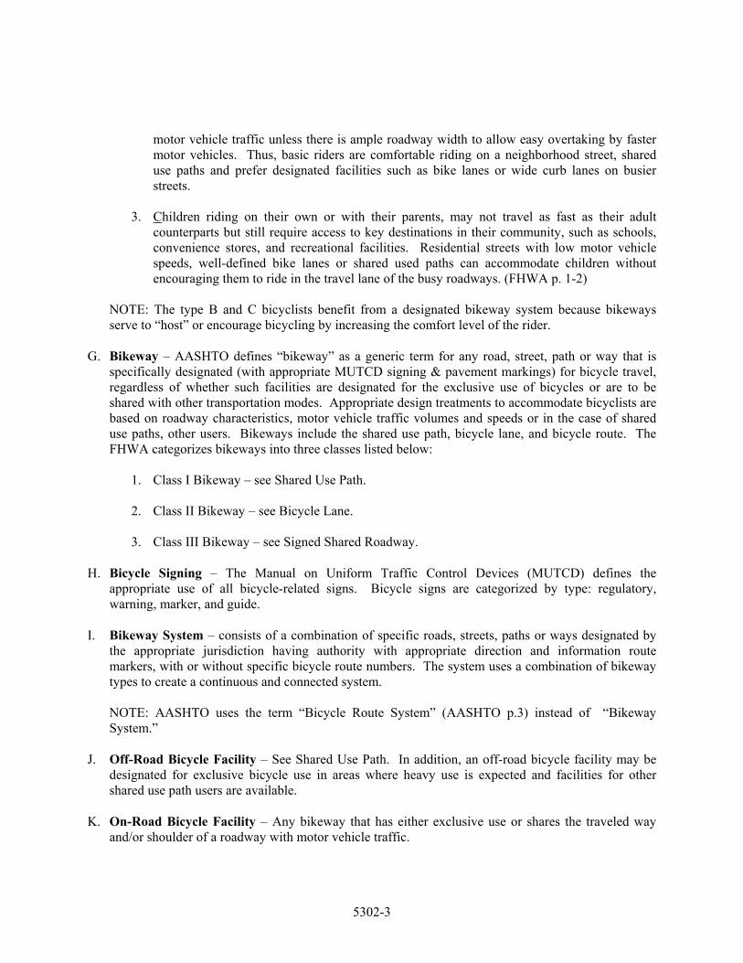
NOTE: The type B and C bicyclists benefit from a designated bikeway system because bikeways serve to “host” or encourage bicycling by increasing the comfort level of the rider.
G. Bikeway – AASHTO defines “bikeway” as a generic term for any road, street, path or way that is
specifically designated (with appropriate MUTCD signing & pavement markings) for bicycle travel, regardless of whether such facilities are designated for the exclusive use of bicycles or are to be shared with other transportation modes. Appropriate design treatments to accommodate bicyclists are based on roadway characteristics, motor vehicle traffic volumes and speeds or in the case of shared use paths, other users. Bikeways include the shared use path, bicycle lane, and bicycle route. The FHWA categorizes bikeways into three classes listed below:
1. Class I Bikeway – see Shared Use Path.
2. Class II Bikeway – see Bicycle Lane.
3. Class III Bikeway – see Signed Shared Roadway.
H. Bicycle Signing – The Manual on Uniform Traffic Control Devices (MUTCD) defines the
appropriate use of all bicycle-related signs. Bicycle signs are categorized by type: regulatory, warning, marker, and guide.
I. Bikeway System – consists of a combination of specific roads, streets, paths or ways designated by
the appropriate jurisdiction having authority with appropriate direction and information route markers, with or without specific bicycle route numbers. The system uses a combination of bikeway types to create a continuous and connected system.
NOTE: AASHTO uses the term “Bicycle Route System” (AASHTO p.3) instead of “Bikeway System.”
J. Off-Road Bicycle Facility – See Shared Use Path. In addition, an off-road bicycle facility may be designated for exclusive bicycle use in areas where heavy use is expected and facilities for other shared use path users are available.
K. On-Road Bicycle Facility – Any bikeway that has either exclusive use or shares the traveled way
and/or shoulder of a roadway with motor vehicle traffic.
5302-3
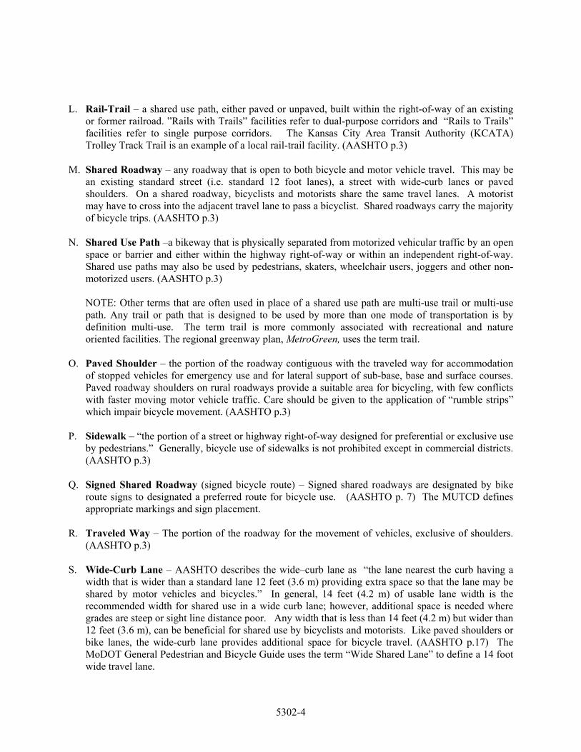
L. Rail-Trail – a shared use path, either paved or unpaved, built within the right-of-way of an existing or former railroad. ”Rails with Trails” facilities refer to dual-purpose corridors and “Rails to Trails” facilities refer to single purpose corridors. The Kansas City Area Transit Authority (KCATA) Trolley Track Trail is an example of a local rail-trail facility. (AASHTO p.3)
M. Shared Roadway – any roadway that is open to both bicycle and motor vehicle travel. This may be
an existing standard street (i.e. standard 12 foot lanes), a street with wide-curb lanes or paved shoulders. On a shared roadway, bicyclists and motorists share the same travel lanes. A motorist may have to cross into the adjacent travel lane to pass a bicyclist. Shared roadways carry the majority of bicycle trips. (AASHTO p.3)
N. Shared Use Path –a bikeway that is physically separated from motorized vehicular traffic by an open
space or barrier and either within the highway right-of-way or within an independent right-of-way. Shared use paths may also be used by pedestrians, skaters, wheelchair users, joggers and other non-motorized users. (AASHTO p.3)
NOTE: Other terms that are often used in place of a shared use path are multi-use trail or multi-use path. Any trail or path that is designed to be used by more than one mode of transportation is by definition multi-use. The term trail is more commonly associated with recreational and nature oriented facilities. The regional greenway plan, MetroGreen, uses the term trail.
O. Paved Shoulder – the portion of the roadway contiguous with the traveled way for accommodation of stopped vehicles for emergency use and for lateral support of sub-base, base and surface courses. Paved roadway shoulders on rural roadways provide a suitable area for bicycling, with few conflicts with faster moving motor vehicle traffic. Care should be given to the application of “rumble strips” which impair bicycle movement. (AASHTO p.3)
P. Sidewalk – “the portion of a street or highway right-of-way designed for preferential or exclusive use
by pedestrians.” Generally, bicycle use of sidewalks is not prohibited except in commercial districts. (AASHTO p.3)
Q. Signed Shared Roadway (signed bicycle route) – Signed shared roadways are designated by bike
route signs to designated a preferred route for bicycle use. (AASHTO p. 7) The MUTCD defines appropriate markings and sign placement.
R. Traveled Way – The portion of the roadway for the movement of vehicles, exclusive of shoulders.
(AASHTO p.3) S. Wide-Curb Lane – AASHTO describes the wide–curb lane as “the lane nearest the curb having a
width that is wider than a standard lane 12 feet (3.6 m) providing extra space so that the lane may be shared by motor vehicles and bicycles.” In general, 14 feet (4.2 m) of usable lane width is the recommended width for shared use in a wide curb lane; however, additional space is needed where grades are steep or sight line distance poor. Any width that is less than 14 feet (4.2 m) but wider than 12 feet (3.6 m), can be beneficial for shared use by bicyclists and motorists. Like paved shoulders or bike lanes, the wide-curb lane provides additional space for bicycle travel. (AASHTO p.17) The MoDOT General Pedestrian and Bicycle Guide uses the term “Wide Shared Lane” to define a 14 foot wide travel lane.
5302-4
5302.3 Mitigating Hazards to Bicycle Travel A critical step to making Kansas City regional area a more bicycle-friendly region is to embrace the concept that every street is a bicycling street.
“To varying extents, bicycles will be ridden on all roadways where they are permitted. All new roadways except those where bicyclists will be legally prohibited, should be designed and constructed under the assumption that they will be used by bicyclists.” AASHTO 1999
Planners should investigate the opportunity to make at least minor or marginal improvements to bicycle travel. Designing, constructing and retrofitting roadways to better accommodate bicycle use means mitigating basic hazards to bicycle travel. These hazards include wheel-eating drainage grates, dangerous railroad crossings, unresponsive traffic signals, general spot improvements and enhanced maintenance practices. For the most part, the mitigation of hazards is inexpensive and can be accomplished within routine maintenance and improvement schedules and budgets. Hazard mitigation and roadway maintenance practices are addressed in the 1999 AASHTO Guide for the Development of Bicycle Facilities on pages 60, 64 and 73. (See also, the Quick Reference Guide on Appendix B of this report.) A. Drainage Grates
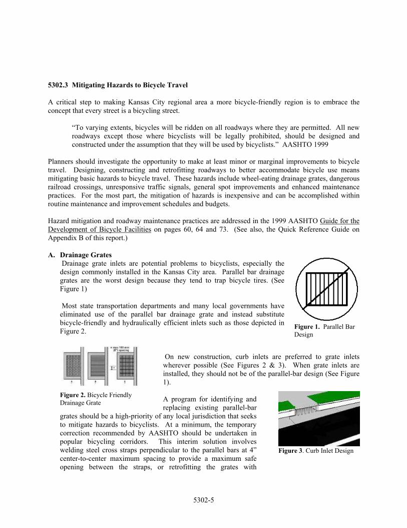
Figure 1. Parallel Bar Design
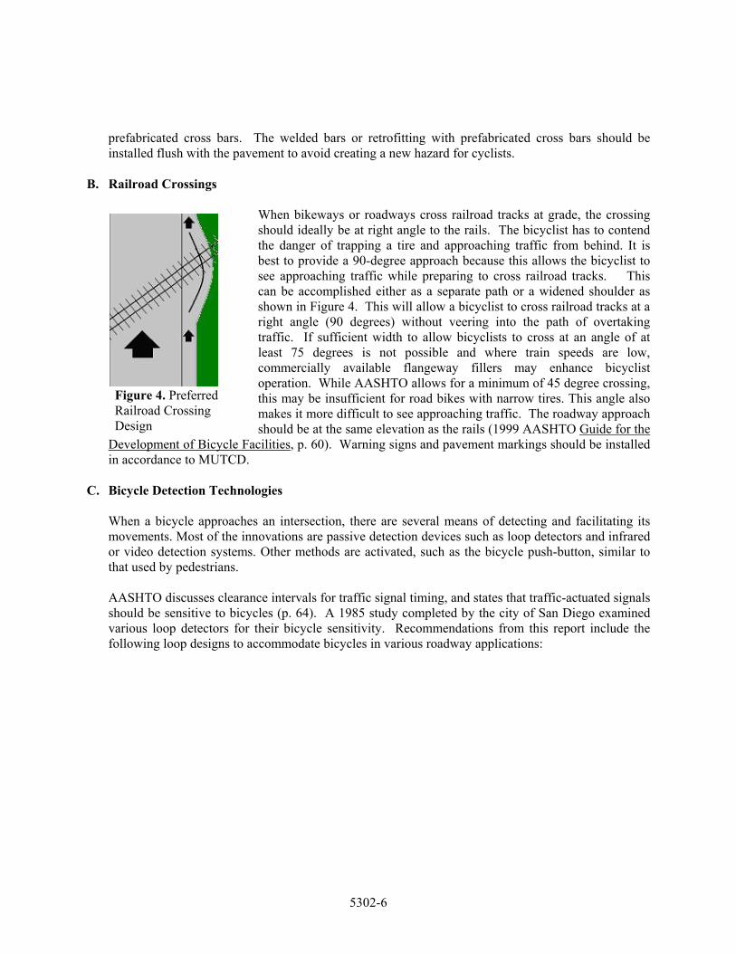
Drainage grate inlets are potential problems to bicyclists, especially the design commonly installed in the Kansas City area. Parallel bar drainage grates are the worst design because they tend to trap bicycle tires. (See Figure 1) Most state transportation departments and many local governments have eliminated use of the parallel bar drainage grate and instead substitute bicycle-friendly and hydraulically efficient inlets such as those depicted in Figure 2.
On new construction, curb inlets are preferred to grate inlets wherever possible (See Figures 2 & 3). When grate inlets are installed, they should not be of the parallel-bar design (See Figure 1). A program for identifying and replacing existing parallel-bar
grates should be a high-priority of any local jurisdiction that seeks to mitigate hazards to bicyclists. At a minimum, the temporary correction recommended by AASHTO should be undertaken in popular bicycling corridors. This interim solution involves welding steel cross straps perpendicular to the parallel bars at 4” center-to-center maximum spacing to provide a maximum safe opening between the straps, or retrofitting the grates with
Figure 2. Bicycle Friendly Drainage Grate
Figure 3. Curb Inlet Design
5302-5
prefabricated cross bars. The welded bars or retrofitting with prefabricated cross bars should be installed flush with the pavement to avoid creating a new hazard for cyclists.
B. Railroad Crossings
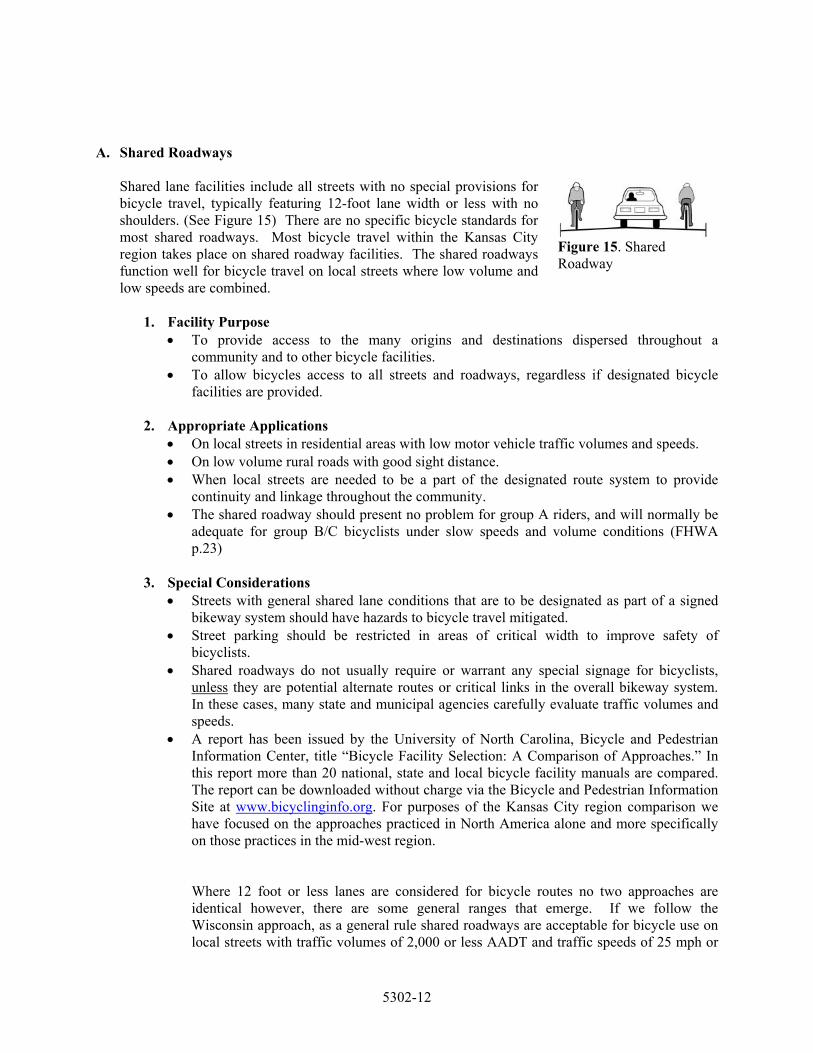
When bikeways or roadways cross railroad tracks at grade, the crossing should ideally be at right angle to the rails. The bicyclist has to contend the danger of trapping a tire and approaching traffic from behind. It is best to provide a 90-degree approach because this allows the bicyclist to see approaching traffic while preparing to cross railroad tracks. This can be accomplished either as a separate path or a widened shoulder as shown in Figure 4. This will allow a bicyclist to cross railroad tracks at a right angle (90 degrees) without veering into the path of overtaking traffic. If sufficient width to allow bicyclists to cross at an angle of at least 75 degrees is not possible and where train speeds are low, commercially available flangeway fillers may enhance bicyclist operation. While AASHTO allows for a minimum of 45 degree crossing, this may be insufficient for road bikes with narrow tires. This angle also makes it more difficult to see approaching traffic. The roadway approach should be at the same elevation as the rails (1999 AASHTO Guide for the
Development of Bicycle Facilities, p. 60). Warning signs and pavement markings should be installed in accordance to MUTCD.
Figure 4. Preferred Railroad Crossing Design
C. Bicycle Detection Technologies
When a bicycle approaches an intersection, there are several means of detecting and facilitating its movements. Most of the innovations are passive detection devices such as loop detectors and infrared or video detection systems. Other methods are activated, such as the bicycle push-button, similar to that used by pedestrians. AASHTO discusses clearance intervals for traffic signal timing, and states that traffic-actuated signals should be sensitive to bicycles (p. 64). A 1985 study completed by the city of San Diego examined various loop detectors for their bicycle sensitivity. Recommendations from this report include the following loop designs to accommodate bicycles in various roadway applications:
5302-6

Figure 5.
Diagonal Quadruple Loop Due to the sensitivity over the entire width of the loop, the diagonal quadruple is the preferred option for shared roadway situations where the exact location of the bicycle cannot be easily predicted. (See Figure 5)
Figure 6.
Quadruple Loop The recommended loop type for use within bicycle lanes is the quadruple. This design detects most strongly over the center wires and is relatively insensitive to vehicles in adjacent lanes. (See Figure 6)
Figure 7.
Standard Loop Standard loops are least desirable for detecting bicycles because they are most sensitive over the wires that form the outer edge of the loop. Unless bicyclists know exactly where to position themselves over the loop, they will not be detected. (See Figure 7)
AASHTO recommends the use of a bicycle detector pavement marking to indicate the optimum location for bicycle detection. A standard pavement symbol can be found on page 66 of the AASHTO guide. Alternatives to pavement loops include use of video cameras to detect bicycle and other traffic and use of microwave sensors.
D. Bicycle Detection Using Video Cameras
Video systems are used to activate treatments such as signal timing specifically needed to assist bicyclists to cross at signalized intersections. This system is useful at signalized intersections where there are dedicated bicycle lanes. The video system uses detectors drawn in video images to sense the presence of bicycles in bicycle lanes at signalized intersections. Figure 8 shows the layout of bicycle lane loops drawn in a video image on the approach to a signalized intersection. The computer system is capable of sensing up to 60 different detection zones within a single intersection for a cost comparable to loop detectors buried within the pavement. The loops to detect motorized vehicle traffic are also shown. Areas labeled Z 7 and Z 6 are bicycle lane detection zones.
Figure 8. Video Layout
5302-7

1. Advantages to the video system: • Special signal timing can be activated to allow bicyclists sufficient time to cross the
intersection. This treatment enhances safety for this mode of transportation. • It will detect bicycles that do not contain iron, unlike loop detectors. • It is not affected by asphalt work and may be used to help direct traffic during
construction.
2. Disadvantages of the video system: • Longer phases needed for bicyclists may disrupt signal progression if cycle lengths are
based on shorter phases. • Since bicyclists do not always stop in the same place while waiting to cross a street,
cameras may either falsely detect a bicyclist or may not detect a bicyclist that is present, in both cases causing unnecessary delay for road users.
• Weather conditions such as thick fog and blinding sunlight can reduce the effectiveness of the camera.
E. Remote Traffic Microwave Sensor Detection (RTMS)
Microwave sensors detect bicycles at signalized intersections using frequency modulated continuous wave radio signals that detect objects in the roadway. This method can detect slow moving or stopped vehicles unlike Doppler. It is also marked with a time code, which gives information on how far away the object is. This technology can also be used to count vehicles. Many new systems have storage and data download capabilities to remote locations. (See Figure 9)
Figure 9. RTMS Layout 1. Advantages of this technology:
• Can detect slow moving or stopped objects. • Not affected by extremes in light or temperature, weather conditions such as fog that may
obstruct video cameras, or road/utility work. • RTMS can detect bicycles that do not contain iron. • The waves refract around large vehicles so smaller vehicles are still “visible.”
2. Disadvantages of this technology:
• Microwave systems are more expensive than standard loops. • According to Electronic Integrated Systems, Inc (EIS), RTMS has never been deployed
for the sole purpose of detecting bicycles. • It may have trouble detecting smaller objects, including young children, or young
children on bicycles.
5302-8

F. Bicycle Push Button/Bar
The bicyclist activates the signal by pushing a bar or button similar to those used for pedestrians, but the button is installed in a location convenient for bicyclists and the signal timing is set appropriately for bicyclists. The sign plate located above the push button/pad/bar indicates that it is not for the use of pedestrians. (See Figure 10) The larger the surface of the button, the easier it is for cyclists to use, thus a push pad is preferential to a push button, and a push bar is preferential to a push pad, as it can be actuated without removing one’s hands from the handlebars.
Figure 10. Bicycle Push Button
1. Advantages of this technology:
• Allows separate signal timings for different user needs • Usually less expensive than other detection treatments
2. Disadvantages of this technology:
• Location of push button does not, in most cases, allow the bicyclist to prepare appropriately for through or left turning maneuvers at the intersection.
• Forces the bicyclist to stop completely to actuate the signal.
Fine-tuning existing traffic detection systems may also improve bicycling conditions. Signal timing should include a minimum green time that allows cyclists to remount their bikes and travel across the intersection, and a yellow/red time that provides a safe bicycle clearance interval. Generally, 2 – 3 seconds added to the minimum automobile green time is appropriate; a yellow interval of 3.0 to 6.0 seconds offers sufficient time for a cyclist to come to a complete stop or enter the intersection legally; and an all-red clearance interval greater than 2.0 seconds is needed to clear bicycles from most intersections.
G. Transition Areas
Abrupt changes in the pavement width of the right travel lane or shoulder should be discouraged. While skilled bicyclists will ride in a straight line by guiding off the lane stripe, many riders will unpredictably move right or left as the lane or shoulder widens or narrows.
Figure 11. MUTCD W5-2
Special transition problems frequently occur at bridges and structures, either when traffic lanes merge to cross a narrow bridge, or when a narrow roadway approaches a new, wider bridge. In the first situation, warning may be provided to both bicyclists and motorists by using the standard MUTCD W5-2 “Narrow Bridge” sign (see Figure 11) in advance of any bridge or culvert having a roadway clearance less than the width of the approach pavement.
5302-9

An additional treatment for unavoidable obstacles such as narrow bridges is to use zebra warning striping on the bridge shoulders, as recommended by the New Jersey DOT and depicted in Figure 12 to the left. The stripes function to divert motor vehicle traffic away from the bridge parapet thus providing additional operating space on the right-hand side of the bridge for cyclists.
Figure 12. Transition Area
For the second situation, safe bicycle passage may be accommodated in the transition from a wide structure to a narrow roadway by continuing the extra operating width of the bridge shoulders or wide outside lanes for at least 100 feet on either side of the bridge. If on- or off-ramps or intersections are present, the shoulder or wide curb lane treatment should continue at least as far as the ramps or intersection.
The best way to avoid transition problems is to design adequate width into the bridge during construction. Several new bridges in the greater Kansas City area have accommodated bicycle traffic in this way and at the same time improved conditions for motorists.
H. Adequate Maintenance
The operation, maintenance and policing of bicycle facilities should be established prior to construction. Additional hazards to bicycle travel may include gaps in longitudinal paving joints, potholes, bumps and other pavement surface irregularities, which may be eliminated through low-cost maintenance repairs.
Figure 13. City of Portland Bicycle Facility Improvement Request Form.
Routine maintenance practices, or lack thereof, may also increase bicyclist sensitivity to gravel, sand, glass, and other roadway debris. Piling snow on the right-hand pavement edge adds debris to roadway shoulders and travel areas where bicyclists most frequently ride. Failure to routinely sweep these areas effectively reduces the operating space for bicycles on a roadway. The city of Seattle has developed an innovative program for locating such minor repairs and maintenance problems. The request form is a tool for the public to help identify maintenance needs. Other cities have adopted this same model. The City of Portland uses the post card size request from shown above in Figure 13. The bicycle improvement program is intended to enhance bicycle safety and encourage bicycling through low-cost, small-scale improvements suggested by concerned bicyclists (e.g., pavement maintenance, hazard removal, bicycle rack installation, and drainage grate
5302-10

repair. A similar program is recommended for local communities within the Kansas City area, combined with enhanced street cleaning for implementation.
I. Construction Zones
Construction zones can account for an inordinate amount of the safety and liability problems. This is unfortunate and unnecessary because preparing a detour plan can ensure public safety and minimizes disruption where possible. Hazards to bicyclists may include: signs, equipment, or debris in the bikeway, blocked access without advance warning, rough pavement or gravel without advance warning, poor pavement transitions, especially when parallel to the line of travel (e.g.: metal plate edges or pavement removal/resurface areas which are not tapered). To address these hazards, it is suggested that detour signs be posted to direct bicyclists to an alternate route. Warning signs alert riders to construction or rough surfaces and debris should be removed regularly. (See Figure 14) Figure 14. Bicycle Detour
Sign, City of Denver, Co. Conclusion: The previously discussed hazards should be mitigated on all roads to be used by bicyclists. As stated in AASHTO, “The majority of bicycling will take place on ordinary roads with no dedicated space for bicyclists. Bicyclists can be expected to ride on almost all roadways.” Therefore, hazard removal should occur on all roadways except for freeways where bicycle travel is prohibited by law. 5302.4 Types of Bicycle Facilities The Kansas City region uses a variety of bicycle facilities to accommodate bicycle travel. The term “bicycle facility” refers to improvements and provisions made by any public agencies in the greater Kansas City area to accommodate and encourage bicycling, including but not limited to: wide-curb lanes, paved shoulders, designated bikeways, bicycle parking and storage and other supporting infrastructure. The purpose of each type of bicycle facility, its appropriate application and special considerations are discussed in this section. Professional judgment and sound engineering practices must be used on the site-specific application of any design treatment. This document describes a wide selection of possible bicycle facility accommodations. There is no one size-fits-all bicycle facility or highway (roadway) design that suits every bicyclist and no bicycle facility design can compensate for a lack of bicycle operator skill and competency. As a result, sound planning and design principles applied within any given transportation corridor may necessitate more than one option to meet the travel and access needs of all potential users. (Paraphrased AASHTO p. 6) In the Kansas City region, typical shared roadways with standard 12-foot travel lanes can accommodate bicycle traffic if traffic volumes are low, travel speeds are low and the roadway is free of hazards. However, various treatments can improve safety for bicyclists along high demand corridors where high traffic volumes and speeds make it prudent to do so. Wide-curb lanes, paved shoulders, and bicycle lanes can be used to accommodate bicycle traffic. Widened roadways provide additional operating room for bicyclists and offer several benefits to motorists, including better accommodation for trucks, buses and other wide vehicles and assisting turning vehicles.
5302-11
A. Shared Roadways
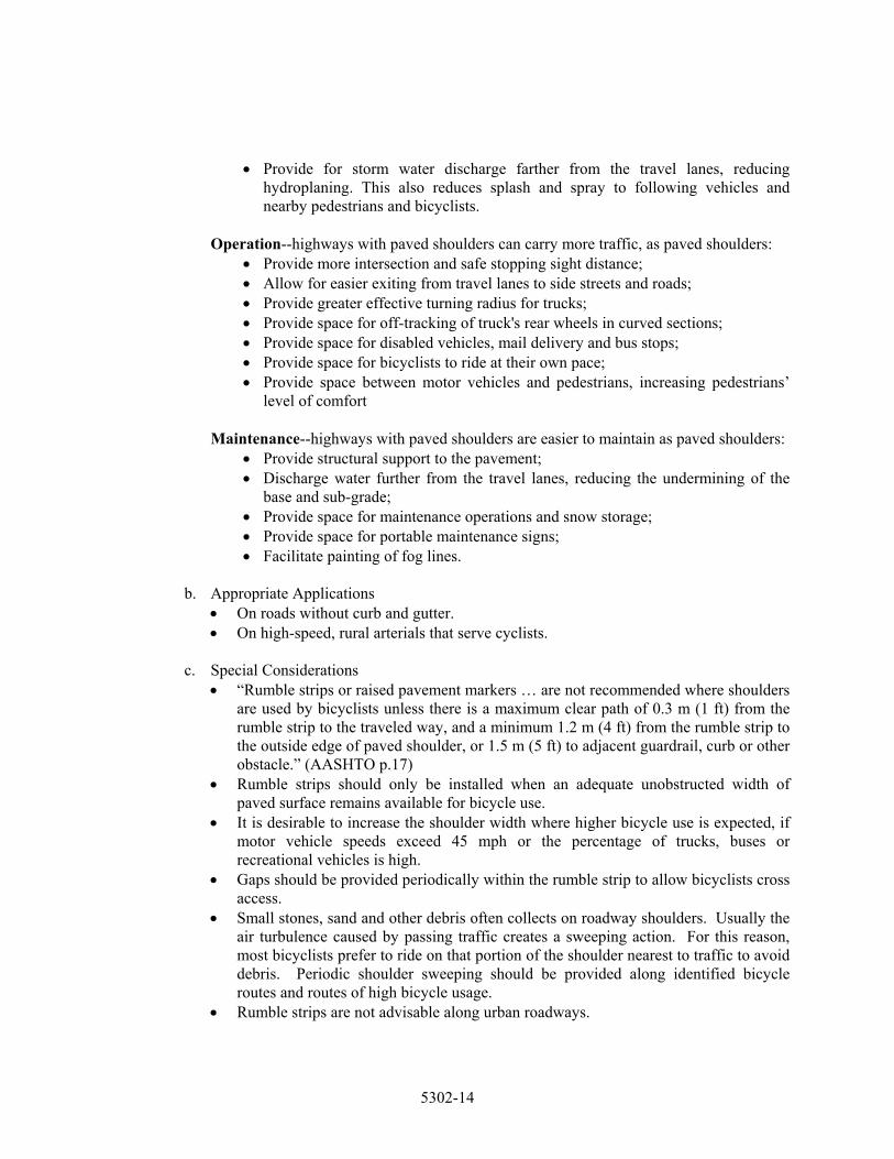
Shared lane facilities include all streets with no special provisions for bicycle travel, typically featuring 12-foot lane width or less with no shoulders. (See Figure 15) There are no specific bicycle standards for most shared roadways. Most bicycle travel within the Kansas City region takes place on shared roadway facilities. The shared roadways function well for bicycle travel on local streets where low volume and low speeds are combined.
Figure 15. Shared Roadway
1. Facility Purpose
• To provide access to the many origins and destinations dispersed throughout a community and to other bicycle facilities.
• To allow bicycles access to all streets and roadways, regardless if designated bicycle facilities are provided.
2. Appropriate Applications
• On local streets in residential areas with low motor vehicle traffic volumes and speeds. • On low volume rural roads with good sight distance. • When local streets are needed to be a part of the designated route system to provide
continuity and linkage throughout the community. • The shared roadway should present no problem for group A riders, and will normally be
adequate for group B/C bicyclists under slow speeds and volume conditions (FHWA p.23)
3. Special Considerations
• Streets with general shared lane conditions that are to be designated as part of a signed bikeway system should have hazards to bicycle travel mitigated.
• Street parking should be restricted in areas of critical width to improve safety of bicyclists.
• Shared roadways do not usually require or warrant any special signage for bicyclists, unless they are potential alternate routes or critical links in the overall bikeway system. In these cases, many state and municipal agencies carefully evaluate traffic volumes and speeds.
• A report has been issued by the University of North Carolina, Bicycle and Pedestrian Information Center, title “Bicycle Facility Selection: A Comparison of Approaches.” In this report more than 20 national, state and local bicycle facility manuals are compared. The report can be downloaded without charge via the Bicycle and Pedestrian Information Site at www.bicyclinginfo.org. For purposes of the Kansas City region comparison we have focused on the approaches practiced in North America alone and more specifically on those practices in the mid-west region.
Where 12 foot or less lanes are considered for bicycle routes no two approaches are identical however, there are some general ranges that emerge. If we follow the Wisconsin approach, as a general rule shared roadways are acceptable for bicycle use on local streets with traffic volumes of 2,000 or less AADT and traffic speeds of 25 mph or
5302-12

less. Where volumes and speeds are higher, additional lane width becomes increasing important. Bike lanes and wide curb lanes should be used to improve bicycling conditions.
• Traffic calming devices may be considered to lower traffic volumes or speeds. • In rural areas, the suitability of a shared roadway decreases as traffic speeds increase,
especially on roads with poor sight distance. Where bicycle use or demand is potentially high, rural roads should be widened to include paved shoulders where the travel speeds and volumes are high.
• The share the road sign may be used along shared roadways where the presence of bicyclists is high to increase awareness and improve safety.
B. Design Treatments To Provide Additional Width
Two design treatments are recommended to provide additional roadway width – paved shoulders on rural roadways and wide curb lanes in urban situations. These treatments offer definitive improvements to bicycle travel.
1. Paved Shoulders
Figure 16. Paved Shoulders. (Bike Route Designation Optional)
The AASHTO Guide for the Development of Bicycle Facilities notes that in rural areas "adding or improving paved shoulders often can be the best way to accommodate bicyclists" – and they have the additional attraction of providing a variety of benefits to motorists and other road users as well. As warranted, shoulders may be designated as host bicycle facilities by signing and marking for preferential use similar to bicycle lanes. (See Figure 16)
Paved shoulders are provided on rural highways for a variety of safety, operation and maintenance reasons. Most of these advantages apply to both shoulders on rural highways and to marked, on-street bicycle lanes on urban roadways.
a. Facility Purpose
Safety--highways with paved shoulders have reduced accident rates, as paved shoulders: • Provide space to make evasive maneuvers; • Accommodate driver error by adding recovery area to regain control of a vehicle; • Provide space for inoperative vehicles. • Provide increased sight distance for through vehicles and for vehicles entering
the roadway (in cut sections or brushy areas in rural areas, and in urban areas with many sight obstructions).
• Provide lateral clearance to roadside objects such as guardrail, signs and poles; • Contribute to driving ease and reduced driver strain. • Reduce passing conflicts between motor vehicles and bicyclists and pedestrians.
5302-13
• Provide for storm water discharge farther from the travel lanes, reducing hydroplaning. This also reduces splash and spray to following vehicles and nearby pedestrians and bicyclists.
Operation--highways with paved shoulders can carry more traffic, as paved shoulders:
• Provide more intersection and safe stopping sight distance; • Allow for easier exiting from travel lanes to side streets and roads; • Provide greater effective turning radius for trucks; • Provide space for off-tracking of truck's rear wheels in curved sections; • Provide space for disabled vehicles, mail delivery and bus stops; • Provide space for bicyclists to ride at their own pace; • Provide space between motor vehicles and pedestrians, increasing pedestrians’
level of comfort Maintenance--highways with paved shoulders are easier to maintain as paved shoulders:
• Provide structural support to the pavement; • Discharge water further from the travel lanes, reducing the undermining of the
base and sub-grade; • Provide space for maintenance operations and snow storage; • Provide space for portable maintenance signs; • Facilitate painting of fog lines.
b. Appropriate Applications
• On roads without curb and gutter. • On high-speed, rural arterials that serve cyclists.
c. Special Considerations
• “Rumble strips or raised pavement markers … are not recommended where shoulders are used by bicyclists unless there is a maximum clear path of 0.3 m (1 ft) from the rumble strip to the traveled way, and a minimum 1.2 m (4 ft) from the rumble strip to the outside edge of paved shoulder, or 1.5 m (5 ft) to adjacent guardrail, curb or other obstacle.” (AASHTO p.17)
• Rumble strips should only be installed when an adequate unobstructed width of paved surface remains available for bicycle use.
• It is desirable to increase the shoulder width where higher bicycle use is expected, if motor vehicle speeds exceed 45 mph or the percentage of trucks, buses or recreational vehicles is high.
• Gaps should be provided periodically within the rumble strip to allow bicyclists cross access.
• Small stones, sand and other debris often collects on roadway shoulders. Usually the air turbulence caused by passing traffic creates a sweeping action. For this reason, most bicyclists prefer to ride on that portion of the shoulder nearest to traffic to avoid debris. Periodic shoulder sweeping should be provided along identified bicycle routes and routes of high bicycle usage.
• Rumble strips are not advisable along urban roadways.
5302-14

• Shoulders should be paved and maintained to an equivalent surface standard as regular travel lanes.
• Paved shoulders that are intended for bicycle use should not be routinely used as right turn lanes for vehicular traffic.
2. Wide Curb Lanes
A wide curb lane is a travel lane nearest the curb having a width that is wider than the standard lane 12 feet (3.6 m). The extra width provides space so that motor vehicles and bicycles may share the lane. Where considering a wide curb lane this guide recommends a, 14 foot (4.2 m) lane width for shared use; however, a curb lane with wider than 12 feet (3.6m) can provide marginal benefits to both bicyclists and motorists. A lane that is less than 14 feet (4.2 m) wide but, wider than 3.6m (12 feet) can be beneficial for shared use by bicyclists and motorists. Beyond hazard mitigation, no special design is required.
a. Facility Purpose
• To better accommodate both bicycles and motor vehicles on arterial streets and roadways by providing additional operating room.
Figure 17. Wide Curb Lanes. (14 Foot Width Recommended, Bike Route Designation Optional)
• To maintain the motor vehicle capacity of a right-hand lane when bicyclists also use it.
• To increase the roadway capacity by the number of bicyclists capable of being accommodated.
• To allow motor vehicles to pass bicycles without having to change lanes. • To minimize both real and perceived operating conflicts between bicycles and motor
vehicles.
b. Appropriate Applications • Where there is insufficient room for a dedicated bicycle lane or pave shoulders. • Where there are frequent intersecting commercial driveways or cross streets that
complicate bicycle lane treatment. • Overland Park, KS, Olathe, KS, Lenexa, KS, and Shawnee, KS, have adopted a wide
curb lane configuration that includes an 11-foot inside lane and a 13-foot wide curb lane rather than two 12-foot lanes.
c. Special Considerations • Wide curb lanes may be appropriate on retrofit projects where there are physical
constraints, and all other options have been pursued, such as removing parking or narrowing travel lanes. This treatment is not particularly attractive to type B/C bicyclists because wide curb lanes simply allow a motor vehicle more room to pass cyclists within a travel lane without any pavement markings.
5302-15
• Wide curb lanes on arterial roadways improve the cycling environment even though they may not be designated as a bikeway.
• A wide curb lane integrates bicycle and vehicle traffic and forces recognition and awareness on the part of motorists, particularly at intersections.
• Wide curb lanes on urban arterials accommodate bicycle use, but striped and signed bicycle lanes may encourage increased bicycle use.
• Additional width 14 to 15 feet is recommended on steep grades or where drainage grates, raised reflectors or on-street parking reduce the usable width. Widths greater than 16 ft (4.8 m) encourage the undesirable operation of two motor vehicles in one lane. In this situation, a bike lane or shoulder bikeway should be provided.
5302.5 Designating On-Road Bikeways One of the goals of the MARC Bicycle Element of the Long-Range Transportation Plan is to encourage more people to ride bicycles for short-distance personal, business, social and recreational trips. To realize this increase in use, it may be desirable to provide facilities that act as a “host” to bicycling activities. Bicycle routes, bicycle lanes and bicycle paths are recommended for this purpose. The impact of host facilities is particularly important for casual or infrequent cyclists not adept at riding in traffic. On-street bicycle routes provide information to the bicyclists for the use of secondary streets to connect to on-street bicycle lanes that offer a designated and visible space for bicyclists and can be a significant factor in route choice. Bicycle paths or multi-use trails that are separated from the roadway can serve both transportation and recreation functions and have proven to be significant generators of bicycle use. (See: Appendix B, Quick Reference Guide.) Due to the nature and frequency of bicycle trips made near college campuses and schools, it is particularly advantageous to provide a designated bikeway system.
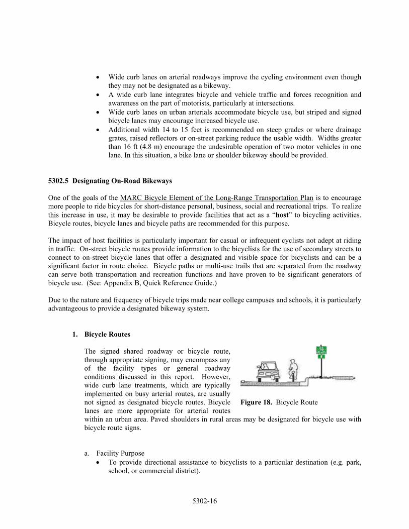
1. Bicycle Routes
The signed shared roadway or bicycle route, through appropriate signing, may encompass any of the facility types or general roadway conditions discussed in this report. However, wide curb lane treatments, which are typically implemented on busy arterial routes, are usually not signed as designated bicycle routes. Bicycle lanes are more appropriate for arterial routes within an urban area. Paved shoulders in rural areas may be designated for bicycle use with bicycle route signs.
Figure 18. Bicycle Route
a. Facility Purpose • To provide directional assistance to bicyclists to a particular destination (e.g. park,
school, or commercial district).
5302-16
• To provide continuity between bicycle lanes, shared use paths or other bicycle facilities.
• To indicate to cyclists that there are particular advantages to using a route as compared with alternative routes.
• Informs motorist of preferred bicyclist’s route indicating greater frequency of encounters.
b. Appropriate Applications
• Where signage is desired to guide bicyclists to their destinations. • In order to provide directional information, a standard sign should be supplemented
with arrow plates, names of routes, distances to destinations, etc • Designated routes may follow a combination of facility types: paved shoulders, wide
curb lanes, multi-use trails and general shared roadway conditions that have compatible motor vehicle volumes and speeds.
c. Special Considerations
• Bicycle route signage is not recommended for routine use on major arterials with general shared roadway conditions, or even wide curb lane treatments. The implementation of bicycle lanes, or designation of less traveled alternative routes, are preferred treatments. If no alternative exists, "Share the Road" caution signs may be used until conditions can be improved.
• For reasons of safety and liability, designated bicycle routes should meet national minimum guidelines and hazards to bicycle travel (parallel drainage grates, rough railroad crossings, etc.) should be properly mitigated before they are signed.
d. Retrofit Guidelines for Signing Bicycle Routes
Bicycle routes often comprise the most significant portion of a bikeway system. The bicycle route is selected based on criteria that give the bicyclists a reason to select the preferred route. Bicycle routes may be designated on local streets, with fewer than 2,000 vehicles per day, where traffic speeds are at or below 25 mph or along collector roadways with wide curb lanes (see Appendix C). The MARC Bicycle Element encourages routing bicycle facilities on roadways that do not present potential problems associated with high speed/multi-lane intersections. After bicycle demand corridors are identified, an inventory of roadway characteristics may be used to select specific routes. The inventory might include: traffic volumes, traffic speeds, street width, presence/absence of curbs, availability of parking and parking usage, stop sign presence at each intersection, difficulty crossing major intersections, surface quality, roadway hazards, terrain/topography, connectivity, access, destinations, directness and other relevant observations. Other approaches to bicycle planning and facility design includes: reducing vehicular speeds or traffic volumes to accommodate bicycles on streets that may not be wide enough for striped bike lanes. Traffic calming treatments may be used to improve safety and increase the attractiveness of a corridor. Many local residential streets are not being considered high bicycle demand corridors and the need to designate them as bikeways is unwarranted, regardless of roadway characteristics. Generally, bicycle routes are not recommended along roadways with high traffic volumes above 2,000 ADT and traffic
5302-17
speeds above 25 mph without the provision of wide curb lanes or paved shoulders. Bicycle lanes are better suited along these high bicycle demand corridors where traffic volumes and speeds are greater.
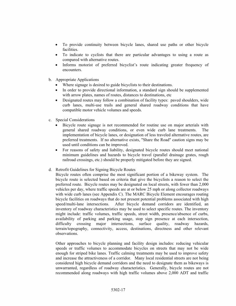
2. Bicycle Lanes
Figure 19. Typical Bicycle Lane
Bicycle lanes are designated portions of a roadway, a minimum of 4 feet wide (5 feet preferred) excluding curb and gutter, that are signed, striped and marked for bicycle use. If the bicycle lane is placed between the parking area and travel lane, the minimum width should be 5 feet.
a. Facility Purpose
• To improve conditions for cyclists of all abilities within a given corridor. • To encourage increased bicycle use on a given roadway by providing a greater
degree of comfort and perceived safety for less skilled cyclists. • Movement by bicyclists and motorists becomes more predictable. • To establish an overall channeling effect and promote an orderly flow of traffic.
b. Appropriate Applications
• Where significant bicycle demand is expected on arterial and collector roadways. Bike lanes should be considered on collector and arterial roadways where the combination of speed and traffic volume suggests a need.
• On streets where lane designation is not complicated by frequent roadway intersections and commercial driveways.
• On streets with high traffic volumes where cyclists and motorists must frequently pass each other.
• When it is desirable to delineate the right-of-way assigned to cyclists and motorists to provide for movements that are more predictable by each.
• When the route is anticipated to serve a high number of less experienced adult, child and recreational bicyclists.
c. Special Considerations
• While the bicycle lane has been shown to increase overall predictability of traffic flow, the bicycle lane can erroneously increase a cyclist’s confidence that motorists will not stray into his path of travel.
• Bicycle lanes must be clearly marked for one-way travel, with designated facilities provided on both sides of a street or roadway.
• Road debris may collect in bike lanes due to the sweeping action of auto and truck traffic. Local agencies should budget for street sweeping to remove debris as needed.
• Special consideration must be given to the treatment of bicycle lanes on roadways with on-street parking.
• Special consideration must be given to the treatment of bicycle lanes at major intersections. Bike lanes tend to complicate left turn movements for bicyclists at
5302-18

intersections. It is also difficult for bicyclists continuing straight while motor vehicular traffic is turning right.
• Bicycle lanes should be separated from motor vehicle travel lanes with a 6-inch solid white line.
• Sufficient width from the face of the curb should be provided so bicyclists can avoid conflicts with motorists while not having to travel too close to the curb. Most new construction includes a 2-foot curb and gutter section. There is a longitudinal seam that is created where the asphalt surface of the roadway meets the concrete gutter. A minimum 4-foot bicycle lane is recommended from edge of the gutter seam to the bicycle lane strip. Older construction sometimes includes a 1-foot curb and gutter section where the seam has been overlaid up to the face of the curb. In this situation, a 5-foot bicycle lane may be stripped from the edge of curb face to the bicycle lane strip. A 4-foot bicycle lane is not recommended in this instance.
d. Design Treatments Not Recommended
• Two-way bicycle lanes located on one side of a roadway is not generally recommended. (See Figure 20) “Bicycle lanes should be one-way facilities and carry bicycle traffic in the same direction as adjacent motor vehicle traffic. Two-way bicycle lanes on one side of the roadway are not recommended when they result in bicycles riding against the flow of motor vehicle traffic. Wrong-way riding is a major cause of bicycle crashes and violates the rules of the road stated in the Uniform Vehicle Code.” AASHTO p. 22.
Figure 20. Two-Way Bicycle Lanes
• Bicycle lanes placed between the curb
and on-street parking are not generally recommended. (See Figure 21) “Bicycle lanes should always be placed between the parking lane and the motor vehicle lanes. Bicycle lanes should never be placed between the parking lane and the curb lane. This can create obstacles for bicyclists from opening car doors and poor visibility at intersections and driveways, and they prohibit bicyclists from making turns.” AASHTO. P. 23.
Figure 21. Bicycle Lanes Between Curb & Parking.
5302-19
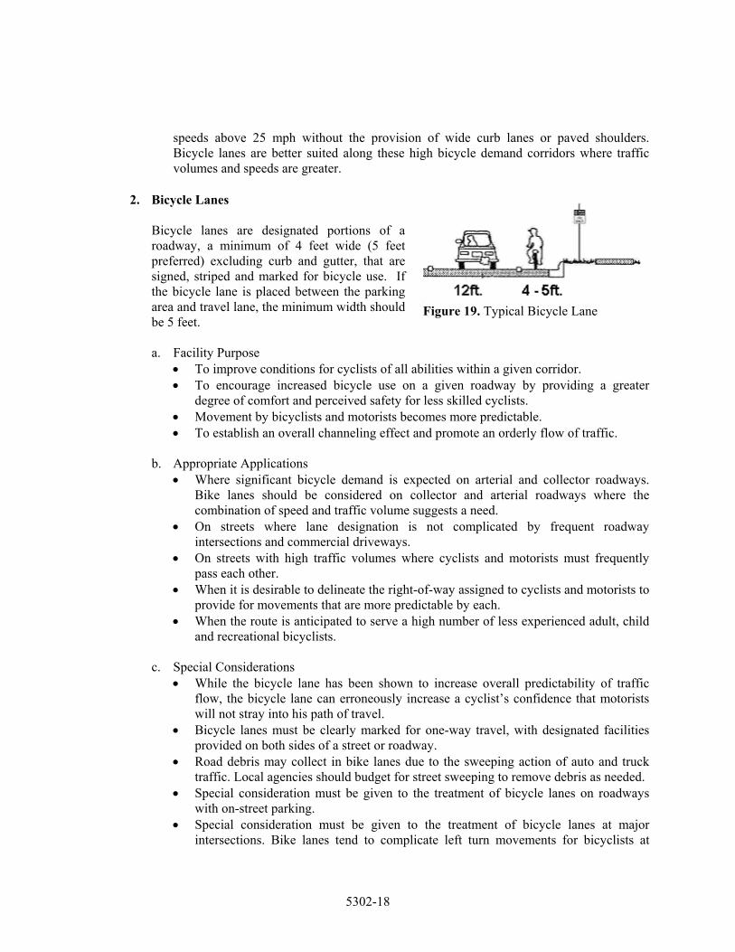
• Continuous right-turn lanes increase conflicts for bicyclists with right-turning and left-turning motorists. Eliminate the continuous right-turn lane, consolidate accesses and create well-defined intersections to improve merging. (See Figure 22)
Figure 22. Continuous right turn lanes
e. Retrofit Guidelines for Bicycle Lanes
Because the population densities and land uses that support bicycling are most often found in the built-up areas of the Kansas City region, retrofitting existing streets and roadways is viewed as a necessity to better accommodate bicycles within urbanized areas. The policy sections of this MARC Bicycle Element address the inclusion of bikeways whenever a road is constructed, reconstructed or relocated; however, existing roadways without bicycle lanes or additional operating width will often act as barriers for bicycle travel throughout the region. The following guidelines are borrowed from the Oregon Department of Transportation to help determine which portions of a roadway may be modified, and by how much to stay within AASHTO minimums, to accommodate on-street bicycle lanes. These modifications can often be made without significantly affecting the safety or operation of a roadway. A traffic engineer should review each project and in some cases a traffic study will be necessary.
f. Reconsider the need for parking
A roadway’s primary function is to move people and goods. It is not to store stationary vehicles. In some cases, parking may only be needed on one side to accommodate residences and/or businesses. Parking can sometimes be narrowed to 7 ft adjacent to a bicycle lane, particularly in areas where traffic calming is being considered.
g. Number of lanes and lane width
In situations where there are four lanes of traffic (two in each direction), and a significant number of left-turn movements, consider the possibility of re-striping for a continuous left-turn lane, two travel lanes and two bicycle lanes.
h. Removal of obstructions
Some older paved or landscaped traffic islands reduce roadway width unnecessarily. If not needed for access control, removal and replacement of raised median islands with
5302-20
pavement markings can often add several feet of useable width. Relocating utility poles, guardrails and other obstructions away from the edge of the roadway can create additional width.
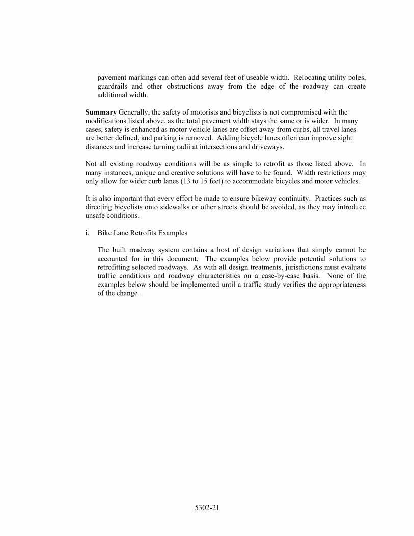
Summary Generally, the safety of motorists and bicyclists is not compromised with the modifications listed above, as the total pavement width stays the same or is wider. In many cases, safety is enhanced as motor vehicle lanes are offset away from curbs, all travel lanes are better defined, and parking is removed. Adding bicycle lanes often can improve sight distances and increase turning radii at intersections and driveways. Not all existing roadway conditions will be as simple to retrofit as those listed above. In many instances, unique and creative solutions will have to be found. Width restrictions may only allow for wider curb lanes (13 to 15 feet) to accommodate bicycles and motor vehicles. It is also important that every effort be made to ensure bikeway continuity. Practices such as directing bicyclists onto sidewalks or other streets should be avoided, as they may introduce unsafe conditions.
i. Bike Lane Retrofits Examples
The built roadway system contains a host of design variations that simply cannot be accounted for in this document. The examples below provide potential solutions to retrofitting selected roadways. As with all design treatments, jurisdictions must evaluate traffic conditions and roadway characteristics on a case-by-case basis. None of the examples below should be implemented until a traffic study verifies the appropriateness of the change.
5302-21
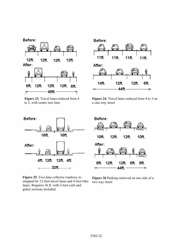
Figure 23. Travel lanes reduced from 4 to 2, with center turn lane
Figure 24. Travel lanes reduced from 4 to 3 on a one-way street
Figure 25. Two-lane collector roadway re-stripped for 12-foot travel lanes and 4-foot bike lanes. Requires 36 ft. with 2-foot curb and gutter sections included.
Figure 26 Parking removed on one side of a two way street
5302-22

5302.6 Providing Designated Off-Road Bicycle Facilities
1. Bike Paths or Shared Use Paths In transportation planning, off-road bicycle facilities are referred to as bicycle paths. However, any path that is open for public use is likely to be popular with walkers, joggers, in-line skaters, pet owners, wheelchair users and others, as well as bicyclists. Hence the terms shared use path and multi-use trail have become synonymous with bicycle path. By any name, these facilities are typically paved trails a minimum of 10 feet wide that are separated from the roadway system and designed for the exclusive use of bicycles and other non-motorized users. The typical trail cross section in Figure 27 depicts minimum path widths and clearances as set by AASHTO. Shared use paths are facilities on exclusive right-of-way and with minimal cross flow by motor vehicles. AASHTO, p. 33.
Figure 27. Shared Use Path
a. Facility Purpose
• To serve significant generators of bicycle use, especially for less skilled cyclists. • To provide enjoyable recreational opportunities as well as desirable commuter routes. • To provide system continuity and linkage in areas where no on-street facilities are
available.
b. Appropriate Applications • Where uninterrupted right-of-way is available to provide long, continuous routes for
commuting or recreation trips. • Within an independent right-of-way such as an abandoned railroad corridor, linear
park, or greenway. • As cut-through between buildings or connections between cul-de-sacs and other
breaks in the street network. • Within a roadway right-of-way only when there is sufficient space or a physical
divider to enforce the concept that the trail functions as an independent highway for bicyclists; and when few streets and driveways intersect with the trail facility.
• It is important to note that bike paths located within a street right-of-way should not be a substitute for bicycle street access. Shared use paths should be thought of as a complementary system of off-road transportation routes for bicyclists that serve as a necessary extension to the roadway network.
c. Special Considerations
• Bicycle paths/multi-use trails attract a variety of user types and therefore need to be designed to accommodate multiple users.
• Recreational trails do not always need to be paved. However, trails should be paved if they are desired to be used for bicycle commuting or transportation trips. Most often, urban and suburban trails are paved to widths of 10 feet or more. Trails in
5302-23
rural areas may be only 8 feet wide and surfaced with limestone screenings or similar material.
• Bike paths/multi-use trails are, by definition, physically separated from motorized traffic. Ideally, they will be grade-separated with a structure at major roadway crossings, unless the crossing roadway volumes are low, or the separation costs are excessively disproportionate to the need or probable use of the bike path.
• Due to safety considerations, sidewalks and walkways immediately adjacent to a roadway are not recommended for designation as bicycle paths or multi-use trail facilities.
• Separated bike paths/multi-use trails parallel to roadways are generally constructed when other types of bikeways are considered hazardous for bicycle travel, such as along heavily traveled metropolitan freeways, and when there is a commitment to provide bike path continuity for an excessive length of the highway corridor.
• Care must be taken to design appropriate transition areas from separated bike paths to on-street bikeways that may include bicycle lanes, wide curb lanes, paved shoulders or general shared-use roadways.
d. Supplemental Design Details The AASHTO Guide covers the design of bicycle paths, intersections and structures on pages 33-46. This detailed discussion is supplemental with the Quick Reference Guide on pages 40-43 of this report and the following text that is intended to further assist the appropriate agencies in developing bicycle paths within the greater Kansas City region.
e. Pavement Structure
Minimum sub-base and asphalt thickness are as recommended in a national trails design guide produced by the Rails-to-Trails Conservancy. However, standard application of this cross section is not recommended without further study. Hard, all-weather pavement surfaces are usually preferred by bicyclists over those of crushed aggregate, sand, clay or stabilized earth since these materials provide a much lower level of service and require higher maintenance. State agencies administering federal funding may add requirements to the type of surface provided if the path is intended for commuting purposes. Each individual bike path must be engineered and designed based upon site-specific sub grade conditions. As a rule, bicycle paths/multi-use trails should be designed to support a minimum design load of 10,000 to 12,500 pounds, which is the weight of a light maintenance truck or ambulance.
f. Trail Widths
Minimum tread widths for bike paths and multi-use trails are generally accepted to be 10 feet. Per AASHTO, an 8-foot width is adequate only where the following conditions prevail: • Bicycle traffic is expected to be low, even on peak days or during peak hours; • Pedestrian use of the facility is not expected to be more than occasional • There will be good horizontal and vertical alignment providing safe and frequent
passing opportunities, and
5302-24

• The path will not be subjected to maintenance vehicle loading conditions that would cause pavement edge damage.
Multi-use trails may need to be even wider to accommodate passing situations for different users traveling at different speeds. Under certain conditions it may be necessary or desirable to increase the width to 12 feet or even 14 feet, due to high traffic, mix of trail users, periodic use by maintenance vehicles, steep grades or poor sight distances.
g. Design Speed
Shared use paths should be designed to accommodate safe travel by the speed of faster bicyclists or in general 20 mph. When a downgrade exceeds 4% or strong prevailing tailwinds exist, 30 mph design speed is advisable. The design speed for unpaved paths is recommended at 15 mph. The maximum super elevation rate to meet Americans with Disabilities requirements (ADA) is 3 percent, and in general, grades should be kept to a maximum of 5 percent. Where unpaved surfaces are used, the grades should be no more than 3 percent to avoid erosion and other maintenance problems.
h. Restriction of Motor Vehicle Traffic
As discussed in AASHTO, entrances to bicycle paths often need some form of physical barrier to prevent unauthorized motor vehicles from using the facilities. The first of two alternatives presented in the AASHTO Guide involves installing posts or bollards in the center and at either edge of the trail. A 5-foot spacing is recommended, as this design allows passage by pedestrians and bicyclists but restricts motor vehicle access. Posts should be at least 3-feet high and reflective for nighttime visibility. The center barrier post may be desired to be a drop-down bollard or removable post that will allow entrance by authorized emergency and maintenance vehicles.
In addition to reflectors or reflective tape on the barrier posts, several state and local agencies have followed California’s lead in recommending 4” yellow pavement striping in an envelope around the posts to assure that their location is well marked and visible to bicyclists, day or night. An alternative design presented by AASHTO is to split the entry way into two 5-foot paths separated by low landscaping to restrict entry to motor vehicles. The Ohio Department of Transportation has further refined this treatment as depicted in Figure 28. This design is the preferred treatment in high volume areas where heavy trail use may limit a bicyclist’s view of the center bollard.
Figure 28. Low Landscape Median Treatment.
5302-25

i. A Design Treatment to Use with Caution “In general, the designated use of a sidewalk (as a signed shared facility) for bicycle travel is unsatisfactory.” AASHTO, p.20 AASHTO goes on to state that, when two-way bike paths are located immediately adjacent to a roadway, some operational problems may occur and that other types of bikeways are likely to be better suited to accommodate bicycle traffic along roadways depending on traffic conditions. Paraphrased, AASHTO, p. 33-35 (See Figure 29)
Figure 29. Bike Path Located Adjacent to a Roadway
Problems with paths immediately adjacent to roadways are summarized below and discussed in greater detail in AASHTO p 33-35 & 58:
1). They require one direction of bicycle traffic to ride against the flow of motor vehicle
traffic, contrary to normal rules of the road. 2). Bicyclists approaching and leaving the path tend to travel on the wrong side of the
street, a major cause of bicycle/motor vehicle crashes. 3). At intersections, motorists often do not notice bicyclists on adjacent paths. 4). Signs posted for roadway users cannot be seen by bicyclists traveling against traffic. 5). When constructed within a narrow road right-of-way, shoulders are often sacrificed,
thus decreasing the safety for roadway users. 6). Many bicyclists will use the roadway instead of the shared use path because of
convenience or safety. 7). Bicyclists on the path must stop or yield often, while bicyclists on the roadway
usually have priority over cross traffic. Bicyclists frequently ignore yield and stop signs.
8). Stopped vehicles exiting side streets or driveways may block the bike path crossing. 9). Barriers are often needed between the path and street, and may create additional
obstructions and maintenance problems. 10). Bicyclist flow is complicated at intersections because it is contrary to the normal flow
of vehicular traffic; pedestrian flow further complicates this design and creates confusion.
5302.7 Special Design Treatments AASHTO acknowledges that bicycle lanes tend to complicate both bicycle and motor vehicle turning movements at intersections. This problem is further complicated at major interchanges where the bicyclist is proceeding straight and the motorist is turning right. The MARC Bicycle Element encourages routing bicycle facilities on roadways that do not present potential problems associated with high speed/multi-lane intersections or cloverleaf freeway interchanges. However, access limitations may necessitate bicycle travel through these areas.
5302-26
In such circumstances, or any situation where it is difficult for cyclists to traverse the undefined area created by right-lane merge movements, the following supplemental guidance is offered. As with all guidance being provided to the various jurisdictions within the Kansas City region, professional judgment and sound engineering practices must be used on the site-specific application of any design treatment. A. Innovative Bicycle Lane and Bicycle Route Designs
MARC encourages innovative bicycle design treatments where appropriate. Several design variations have been tried in other metropolitan communities. These innovative solutions may be used to solve a problem in a particular location or overcome particular barriers to bicycling.
1. Contra-flow Bicycle Lanes
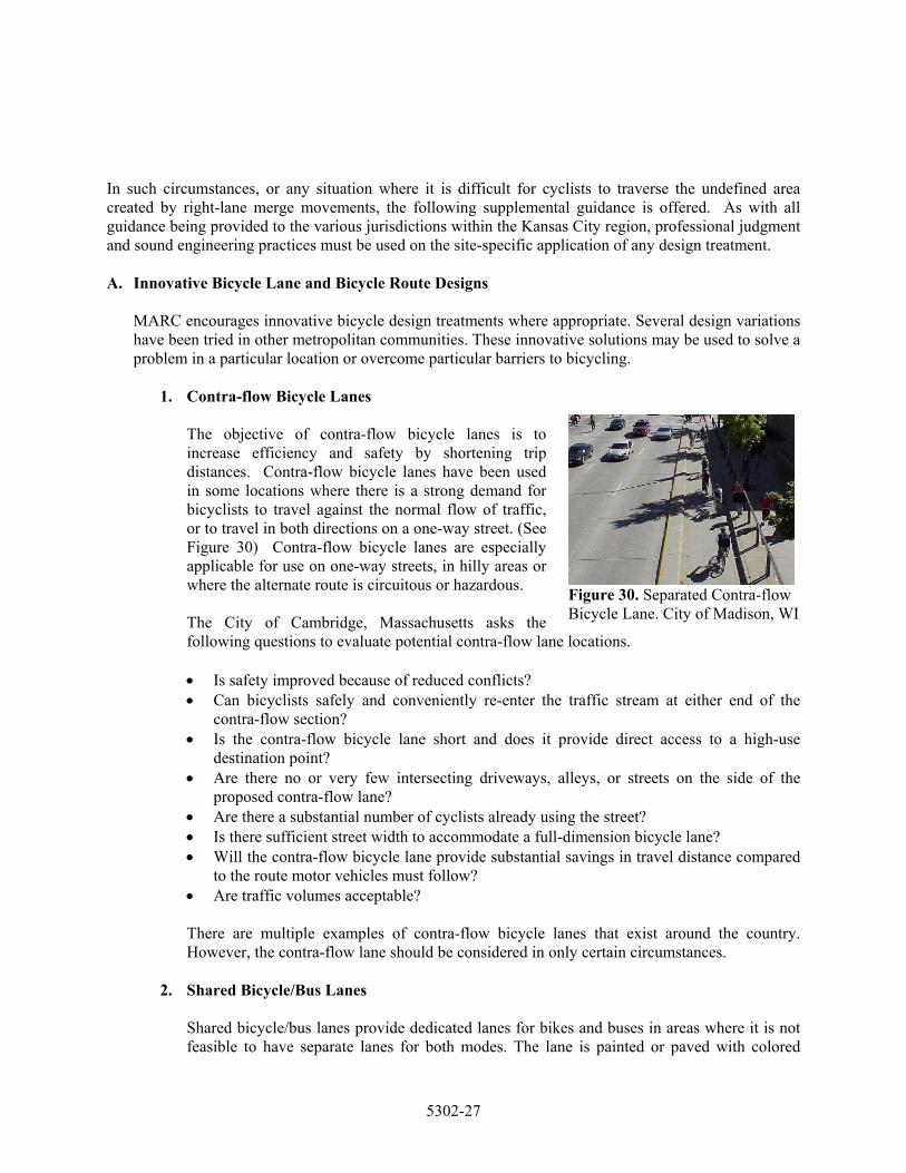
The objective of contra-flow bicycle lanes is to increase efficiency and safety by shortening trip distances. Contra-flow bicycle lanes have been used in some locations where there is a strong demand for bicyclists to travel against the normal flow of traffic, or to travel in both directions on a one-way street. (See Figure 30) Contra-flow bicycle lanes are especially applicable for use on one-way streets, in hilly areas or where the alternate route is circuitous or hazardous. The City of Cambridge, Massachusetts asks the following questions to evaluate potential contra-flow lane locations.
Figure 30. Separated Contra-flow Bicycle Lane. City of Madison, WI
• Is safety improved because of reduced conflicts? • Can bicyclists safely and conveniently re-enter the traffic stream at either end of the
contra-flow section? • Is the contra-flow bicycle lane short and does it provide direct access to a high-use
destination point? • Are there no or very few intersecting driveways, alleys, or streets on the side of the
proposed contra-flow lane? • Are there a substantial number of cyclists already using the street? • Is there sufficient street width to accommodate a full-dimension bicycle lane? • Will the contra-flow bicycle lane provide substantial savings in travel distance compared
to the route motor vehicles must follow? • Are traffic volumes acceptable?
There are multiple examples of contra-flow bicycle lanes that exist around the country. However, the contra-flow lane should be considered in only certain circumstances.
2. Shared Bicycle/Bus Lanes
Shared bicycle/bus lanes provide dedicated lanes for bikes and buses in areas where it is not feasible to have separate lanes for both modes. The lane is painted or paved with colored
5302-27
asphalt to emphasize the lane designation. The lane should be wide enough to allow cyclists to pass a stopped bus. The right lane is stenciled as a diamond lane, with supporting signage and pavement legends that designate the lane for buses and bicycles only. (See Figure 31)
Shared bicycle/bus lanes are commonly used in downtowns where it is difficult to find room for dedicated bicycle lanes. Considerations of shared bicycle/bus lanes include: bicyclists must pass stopped buses on the left whether there is a bicycle lane or not; a dedicated bicycle lane is often unnecessary; provides separation of faster and slower moving traffic; bikes and buses travel at approximately the same average speed and travel time for buses and bikes is improved as they are not hindered by congested auto traffic. Disadvantages of shared bicycle/bus lane include: there is a leap frog effect of buses and bikes; if not designed well, or if turning traffic is allowed use of the lane, benefits of the lane will be reduced. Examples currently include Tucson, AZ.; Madison, WI; Toronto, Ontario; Vancouver, BC; and Philadelphia, PA. These lanes often are used as dedicated right turn lanes.
Philadelphia, PA colors this shared lane red to add emphasis.
Figure 31. Bus/Bike lane, City of Philadelphia, PA.
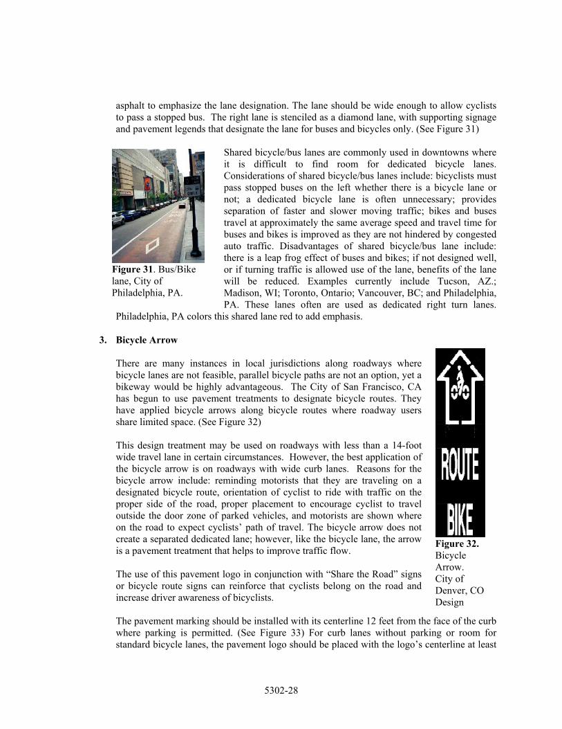
3. Bicycle Arrow
Figure 32. Bicycle Arrow. City of Denver, CO Design
There are many instances in local jurisdictions along roadways where bicycle lanes are not feasible, parallel bicycle paths are not an option, yet a bikeway would be highly advantageous. The City of San Francisco, CA has begun to use pavement treatments to designate bicycle routes. They have applied bicycle arrows along bicycle routes where roadway users share limited space. (See Figure 32) This design treatment may be used on roadways with less than a 14-foot wide travel lane in certain circumstances. However, the best application of the bicycle arrow is on roadways with wide curb lanes. Reasons for the bicycle arrow include: reminding motorists that they are traveling on a designated bicycle route, orientation of cyclist to ride with traffic on the proper side of the road, proper placement to encourage cyclist to travel outside the door zone of parked vehicles, and motorists are shown where on the road to expect cyclists’ path of travel. The bicycle arrow does not create a separated dedicated lane; however, like the bicycle lane, the arrow is a pavement treatment that helps to improve traffic flow. The use of this pavement logo in conjunction with “Share the Road” signs or bicycle route signs can reinforce that cyclists belong on the road and increase driver awareness of bicyclists. The pavement marking should be installed with its centerline 12 feet from the face of the curb where parking is permitted. (See Figure 33) For curb lanes without parking or room for standard bicycle lanes, the pavement logo should be placed with the logo’s centerline at least
5302-28
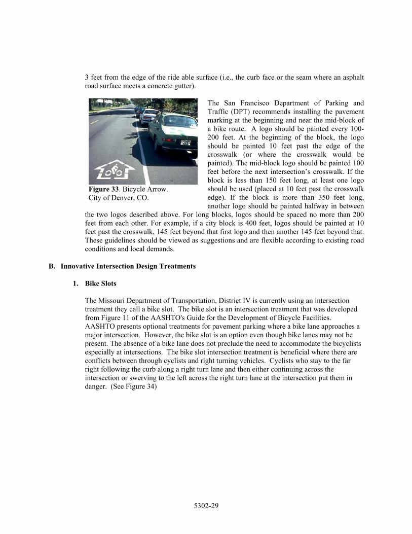
3 feet from the edge of the ride able surface (i.e., the curb face or the seam where an asphalt road surface meets a concrete gutter).
The San Francisco Department of Parking and Traffic (DPT) recommends installing the pavement marking at the beginning and near the mid-block of a bike route. A logo should be painted every 100-200 feet. At the beginning of the block, the logo should be painted 10 feet past the edge of the crosswalk (or where the crosswalk would be painted). The mid-block logo should be painted 100 feet before the next intersection’s crosswalk. If the block is less than 150 feet long, at least one logo should be used (placed at 10 feet past the crosswalk edge). If the block is more than 350 feet long, another logo should be painted halfway in between
the two logos described above. For long blocks, logos should be spaced no more than 200 feet from each other. For example, if a city block is 400 feet, logos should be painted at 10 feet past the crosswalk, 145 feet beyond that first logo and then another 145 feet beyond that. These guidelines should be viewed as suggestions and are flexible according to existing road conditions and local demands.
Figure 33. Bicycle Arrow. City of Denver, CO.
B. Innovative Intersection Design Treatments
1. Bike Slots
The Missouri Department of Transportation, District IV is currently using an intersection treatment they call a bike slot. The bike slot is an intersection treatment that was developed from Figure 11 of the AASHTO's Guide for the Development of Bicycle Facilities. AASHTO presents optional treatments for pavement parking where a bike lane approaches a major intersection. However, the bike slot is an option even though bike lanes may not be present. The absence of a bike lane does not preclude the need to accommodate the bicyclists especially at intersections. The bike slot intersection treatment is beneficial where there are conflicts between through cyclists and right turning vehicles. Cyclists who stay to the far right following the curb along a right turn lane and then either continuing across the intersection or swerving to the left across the right turn lane at the intersection put them in danger. (See Figure 34)
5302-29
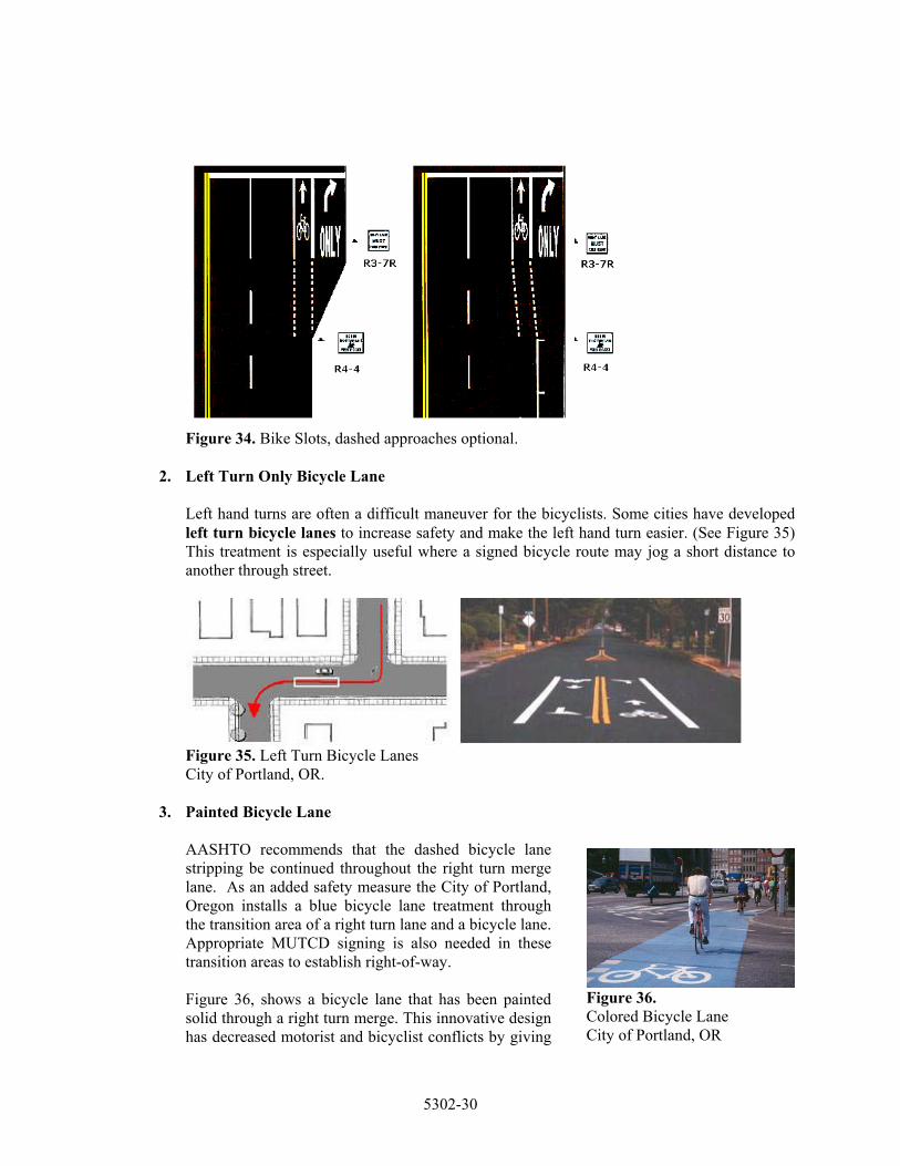
Figure 34. Bike Slots, dashed approaches optional.
2. Left Turn Only Bicycle Lane
Left hand turns are often a difficult maneuver for the bicyclists. Some cities have developed left turn bicycle lanes to increase safety and make the left hand turn easier. (See Figure 35) This treatment is especially useful where a signed bicycle route may jog a short distance to another through street.
Figure 35. Left Turn Bicycle Lanes City of Portland, OR.
3. Painted Bicycle Lane
AASHTO recommends that the dashed bicycle lane stripping be continued throughout the right turn merge lane. As an added safety measure the City of Portland, Oregon installs a blue bicycle lane treatment through the transition area of a right turn lane and a bicycle lane. Appropriate MUTCD signing is also needed in these transition areas to establish right-of-way.
Figure 36. Colored Bicycle Lane City of Portland, OR
Figure 36, shows a bicycle lane that has been painted solid through a right turn merge. This innovative design has decreased motorist and bicyclist conflicts by giving
5302-30
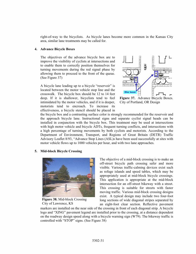
right-of-way to the bicyclists. As bicycle lanes become more common in the Kansas City area, similar lane treatments may be called for.
4. Advance Bicycle Boxes
The objectives of the advance bicycle box are to improve the visibility of cyclists at intersections and to enable them to correctly position themselves for turning movements during the red signal phase by allowing them to proceed to the front of the queue. (See Figure 37) A bicycle lane leading up to a bicycle “reservoir” is located between the motor vehicle stop line and the crosswalk. The bicycle box should be 12 to 14 feet deep. If it is shallower, bicyclists tend to feel intimidated by the motor vehicles, and if it is deeper, motorists tend to encroach. To increase its effectiveness, a bicycle stencil should be placed in the bicycle box and a contrasting surface color is strongly recommended for the reservoir and the approach bicycle lane. Instructional signs and separate cyclist signal heads can be installed in conjunction with the bicycle box. This treatment may be used at intersections with high motor vehicle and bicycle ADTs, frequent turning conflicts, and intersections with a high percentage of turning movements by both cyclists and motorists. According to the Department of Environment, Transport, and Regions of Great Britain (DETR) Traffic Advisory Leaflet 8/93, “Advance Stop Lines (ASL)s have been used successfully at sites with motor vehicle flows up to 1000 vehicles per hour, and with two lane approaches.
Figure 37. Advance Bicycle Boxes. City of Portland, OR Design
5. Mid-block Bicycle Crossing
The objective of a mid-block crossing is to make an off-street bicycle path crossing safer and more visible. Various traffic-calming devices exist such as refuge islands and speed tables, which may be appropriately used at mid-block bicycle crossings. This application is appropriate at the mid-block intersection for an off-street bikeway with a street. This crossing is suitable for streets with faster moving traffic. Various mid-block crossing designs exist. A typical design may include two four-foot long sections of wide diagonal stripes separated by an eight-foot clear section. Reflective pavement
markers are installed on the near side of the crossing in front of each diagonal strip. A bicycle logo and “XING” pavement legend are installed prior to the crossing, at a distance dependent on the roadway design speed along with a bicycle warning sign (W79). The bikeway traffic is controlled with “STOP” signs. (See Figure 38)
Figure 38. Mid-block Crossing City of Lawrence, KS
5302-31
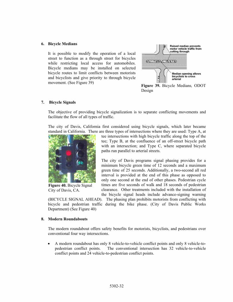
6. Bicycle Medians
Figure 39. Bicycle Medians, ODOT Design
It is possible to modify the operation of a local street to function as a through street for bicycles while restricting local access for automobiles. Bicycle medians may be installed on selected bicycle routes to limit conflicts between motorists and bicyclists and give priority to through bicycle movement. (See Figure 39)
7. Bicycle Signals The objective of providing bicycle signalization is to separate conflicting movements and facilitate the flow of all types of traffic. The city of Davis, California first considered using bicycle signals, which later became standard in California. There are three types of intersections where they are used: Type A, at
tee intersections with high bicycle traffic along the top of the tee; Type B, at the confluence of an off-street bicycle path with an intersection; and Type C, where separated bicycle paths run parallel to arterial streets.
The city of Davis programs signal phasing provides for a minimum bicycle green time of 12 seconds and a maximum green time of 25 seconds. Additionally, a two-second all red interval is provided at the end of this phase as opposed to only one second at the end of other phases. Pedestrian cycle times are five seconds of walk and 18 seconds of pedestrian clearance. Other treatments included with the installation of the bicycle signal heads include advance-signing warning
(BICYCLE SIGNAL AHEAD). The phasing plan prohibits motorists from conflicting with bicycle and pedestrian traffic during the bike phase. (City of Davis Public Works Department) (See Figure 40)
Figure 40. Bicycle Signal City of Davis, CA.
8. Modern Roundabouts
The modern roundabout offers safety benefits for motorists, bicyclists, and pedestrians over conventional four way intersections.
• A modern roundabout has only 8 vehicle-to-vehicle conflict points and only 8 vehicle-to-
pedestrian conflict points. The conventional intersection has 32 vehicle-to-vehicle conflict points and 24 vehicle-to-pedestrian conflict points.
5302-32
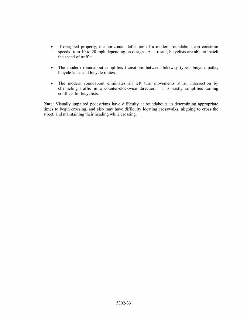
• If designed properly, the horizontal deflection of a modern roundabout can constrain speeds from 10 to 20 mph depending on design. As a result, bicyclists are able to match the speed of traffic.
• The modern roundabout simplifies transitions between bikeway types, bicycle paths,
bicycle lanes and bicycle routes.
• The modern roundabout eliminates all left turn movements at an intersection by channeling traffic in a counter-clockwise direction. This vastly simplifies turning conflicts for bicyclists.
Note: Visually impaired pedestrians have difficulty at roundabouts in determining appropriate times to begin crossing, and also may have difficulty locating crosswalks, aligning to cross the street, and maintaining their heading while crossing.
5302-33
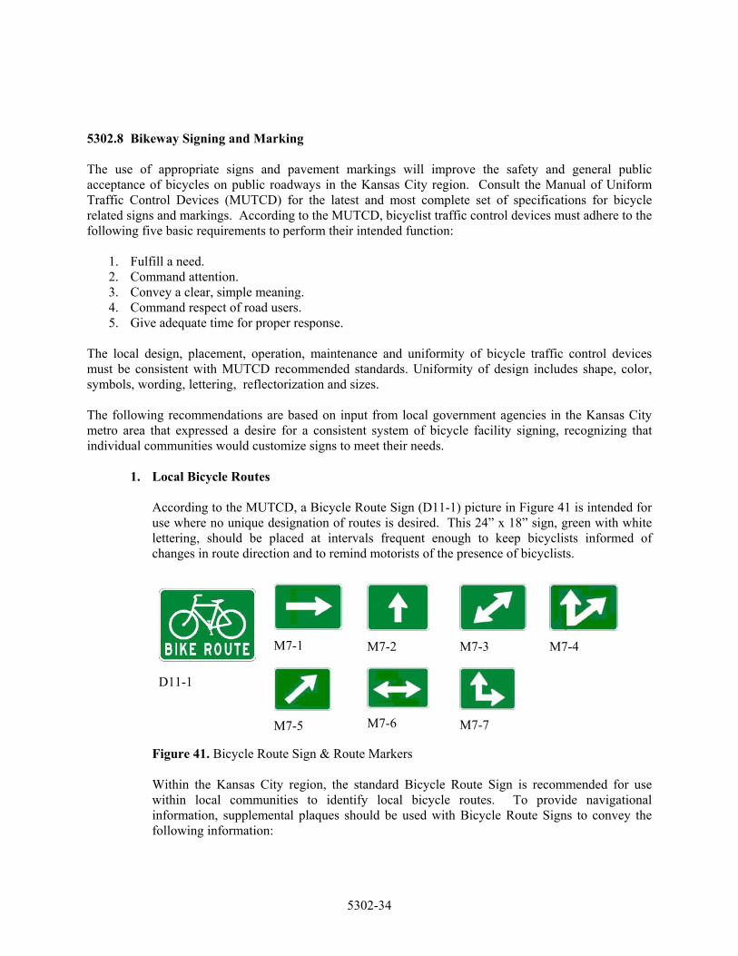
5302.8 Bikeway Signing and Marking The use of appropriate signs and pavement markings will improve the safety and general public acceptance of bicycles on public roadways in the Kansas City region. Consult the Manual of Uniform Traffic Control Devices (MUTCD) for the latest and most complete set of specifications for bicycle related signs and markings. According to the MUTCD, bicyclist traffic control devices must adhere to the following five basic requirements to perform their intended function:
1. Fulfill a need. 2. Command attention. 3. Convey a clear, simple meaning. 4. Command respect of road users. 5. Give adequate time for proper response.
The local design, placement, operation, maintenance and uniformity of bicycle traffic control devices must be consistent with MUTCD recommended standards. Uniformity of design includes shape, color, symbols, wording, lettering, reflectorization and sizes. The following recommendations are based on input from local government agencies in the Kansas City metro area that expressed a desire for a consistent system of bicycle facility signing, recognizing that individual communities would customize signs to meet their needs.
1. Local Bicycle Routes
According to the MUTCD, a Bicycle Route Sign (D11-1) picture in Figure 41 is intended for use where no unique designation of routes is desired. This 24” x 18” sign, green with white lettering, should be placed at intervals frequent enough to keep bicyclists informed of changes in route direction and to remind motorists of the presence of bicyclists.
M7-1
M7-2
M7-3
D11-1
M7-5
M7-6
M7-7
M7-4
Figure 41. Bicycle Route Sign & Route Markers Within the Kansas City region, the standard Bicycle Route Sign is recommended for use within local communities to identify local bicycle routes. To provide navigational information, supplemental plaques should be used with Bicycle Route Signs to convey the following information:
5302-34

• Destination of the route • Distance to the desired destination • Direction of travel
As desired or deemed appropriate, supplemental plaques may also be placed above or below the D11-1 for the following purposes:
• To clarify which community a bicycle route serves • To identify a specific route by local name
2. Regional Bikeways
The region should be served by an interconnected system of bikeways. Recent planning activities such as the City of Kansas City, Missouri Transportation Bicycle Initiative, the Riverfront Heritage Trail, Northland Trails Plan and the update of MetroGreen are aimed at developing an on-road and off-road bikeway system. The MUTCD recommends a Bicycle Route Marker (M1-9) for use where it is desired to establish a unique identification through route designation of a state, regional or local bicycle route. As presented within the MUTCD, the marker should have a numerical designation within a green background on a reflectorized white legend or border. However, due to the multiplicity of jurisdictions responsible for bikeway implementation within the Kansas City metro area, it would be difficult to coordinate a logical and meaningful numbering system across the region that could evolve and expand with new opportunities for bicycle facility construction. For this reason, and because the MUTCD allows for variance in sign design where messages other than those provided in the MUTCD are needed, the following regional signage system is proposed.
Figure 42. Sample MetroGreen Sign
“MetroGreen” route markers (see Figure 42) are appropriate for use in the following situations: • Multi-jurisdictional routes that connect one or more communities • Multi-jurisdictional routes between counties or states • Segments of the MetroGreen system
5302-35
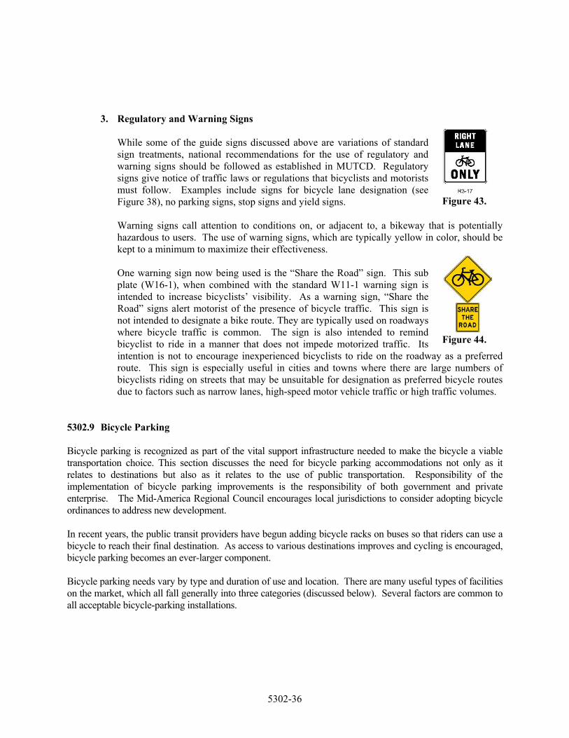
3. Regulatory and Warning Signs
Figure 43.
While some of the guide signs discussed above are variations of standard sign treatments, national recommendations for the use of regulatory and warning signs should be followed as established in MUTCD. Regulatory signs give notice of traffic laws or regulations that bicyclists and motorists must follow. Examples include signs for bicycle lane designation (see Figure 38), no parking signs, stop signs and yield signs. Warning signs call attention to conditions on, or adjacent to, a bikeway that is potentially hazardous to users. The use of warning signs, which are typically yellow in color, should be kept to a minimum to maximize their effectiveness. One warning sign now being used is the “Share the Road” sign. This sub plate (W16-1), when combined with the standard W11-1 warning sign is intended to increase bicyclists’ visibility. As a warning sign, “Share the Road” signs alert motorist of the presence of bicycle traffic. This sign is not intended to designate a bike route. They are typically used on roadways where bicycle traffic is common. The sign is also intended to remind bicyclist to ride in a manner that does not impede motorized traffic. Its intention is not to encourage inexperienced bicyclists to ride on the roadway as a preferred route. This sign is especially useful in cities and towns where there are large numbers of bicyclists riding on streets that may be unsuitable for designation as preferred bicycle routes due to factors such as narrow lanes, high-speed motor vehicle traffic or high traffic volumes.
Figure 44.
5302.9 Bicycle Parking Bicycle parking is recognized as part of the vital support infrastructure needed to make the bicycle a viable transportation choice. This section discusses the need for bicycle parking accommodations not only as it relates to destinations but also as it relates to the use of public transportation. Responsibility of the implementation of bicycle parking improvements is the responsibility of both government and private enterprise. The Mid-America Regional Council encourages local jurisdictions to consider adopting bicycle ordinances to address new development. In recent years, the public transit providers have begun adding bicycle racks on buses so that riders can use a bicycle to reach their final destination. As access to various destinations improves and cycling is encouraged, bicycle parking becomes an ever-larger component. Bicycle parking needs vary by type and duration of use and location. There are many useful types of facilities on the market, which all fall generally into three categories (discussed below). Several factors are common to all acceptable bicycle-parking installations.
5302-36
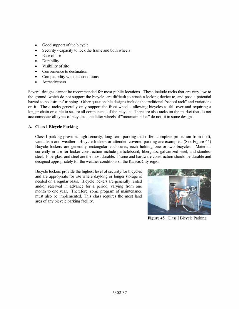
• Good support of the bicycle • Security - capacity to lock the frame and both wheels • Ease of use • Durability • Visibility of site • Convenience to destination • Compatibility with site conditions • Attractiveness
Several designs cannot be recommended for most public locations. These include racks that are very low to the ground, which do not support the bicycle, are difficult to attach a locking device to, and pose a potential hazard to pedestrians' tripping. Other questionable designs include the traditional "school rack" and variations on it. These racks generally only support the front wheel - allowing bicycles to fall over and requiring a longer chain or cable to secure all components of the bicycle. There are also racks on the market that do not accommodate all types of bicycles - the fatter wheels of "mountain bikes" do not fit in some designs. A. Class I Bicycle Parking
Class I parking provides high security, long term parking that offers complete protection from theft, vandalism and weather. Bicycle lockers or attended covered parking are examples. (See Figure 45) Bicycle lockers are generally rectangular enclosures, each holding one or two bicycles. Materials currently in use for locker construction include particleboard, fiberglass, galvanized steel, and stainless steel. Fiberglass and steel are the most durable. Frame and hardware construction should be durable and designed appropriately for the weather conditions of the Kansas City region. Bicycle lockers provide the highest level of security for bicycles and are appropriate for use where daylong or longer storage is needed on a regular basis. Bicycle lockers are generally rented and/or reserved in advance for a period, varying from one month to one year. Therefore, some program of maintenance must also be implemented. This class requires the most land area of any bicycle parking facility.
Figure 45. Class I Bicycle Parking
5302-37
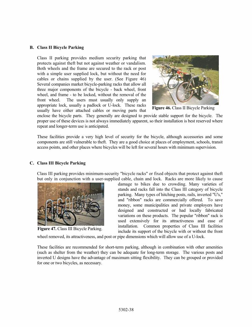
B. Class II Bicycle Parking
Class II parking provides medium security parking that protects against theft but not against weather or vandalism. Both wheels and the frame are secured to the rack or post with a simple user supplied lock, but without the need for cables or chains supplied by the user. (See Figure 46) Several companies market bicycle-parking racks that allow all three major components of the bicycle - back wheel, front wheel, and frame - to be locked, without the removal of the front wheel. The users must usually only supply an appropriate lock, usually a padlock or U-lock. These racks usually have either attached cables or moving parts that enclose the bicycle parts. They generally are designed to provide stable support for the bicycle. The proper use of these devices is not always immediately apparent, so their installation is best reserved where repeat and longer-term use is anticipated.
Figure 46. Class II Bicycle Parking
These facilities provide a very high level of security for the bicycle, although accessories and some components are still vulnerable to theft. They are a good choice at places of employment, schools, transit access points, and other places where bicycles will be left for several hours with minimum supervision.
C. Class III Bicycle Parking
Class III parking provides minimum-security "bicycle racks" or fixed objects that protect against theft but only in conjunction with a user-supplied cable, chain and lock. Racks are more likely to cause
damage to bikes due to crowding. Many varieties of stands and racks fall into the Class III category of bicycle parking. Many types of hitching posts, rails, inverted "U's," and "ribbon" racks are commercially offered. To save money, some municipalities and private employers have designed and constructed or had locally fabricated variations on these products. The popular "ribbon" rack is used extensively for its attractiveness and ease of installation. Common properties of Class III facilities include its support of the bicycle with or without the front
wheel removed, its attractiveness, and post or pipe dimensions which will allow use of a U-lock.
Figure 47. Class III Bicycle Parking.
These facilities are recommended for short-term parking, although in combination with other amenities (such as shelter from the weather) they can be adequate for long-term storage. The various posts and inverted U designs have the advantage of maximum sitting flexibility. They can be grouped or provided for one or two bicycles, as necessary.
5302-38

D. Short-Term vs. Long-Term Bicycle Parking
Short-term bicycle parking is provided for shoppers, customers, messengers and other visitors who generally park for two hours or less. Class II or III facilities are appropriate in this case. A good rule of thumb is that short-term parking should be located within 50 feet of a main entrance of the destination. It is a good idea to distribute short-term parking where there is more than one building on a site, or
where a building has more than one main entrance; the parking must be distributed to serve all buildings or main entrances. Long-term bicycle parking is provided for employees, students, residents, commuters and others who generally stay at a site for several hours. This parking is typically more secure and weather-protected than short-term parking. Class I or II bicycle parking facilities are most appropriate for long-term parking.
Figure 48. Short-term Parking.
Figure 49. Long-term Parking.
1. Bicycle Parking Location
The location of bicycle parking should be determined first. This location should meet the needs of potential users. Lack of adequate bicycle parking facilities and fear of theft are major deterrents for all bicyclists. The visibility of parking and ability of the rack to secure the bike are two important considerations. Bicycle parking should be sited wherever bicycle traffic is expected, in convenient locations. High priority locations include recreational destinations, schools and universities, places of employment, and commercial/retail centers. Consideration may be given to the conversion of auto parking spaces to the bicycle, since six to eight bicycles may be parked in the same space as one car. During installation, it is important to understand how the rack or facility will be used so as not to block access or face the facility in the wrong direction.
2. Additional Considerations
There are several additional features of bicycle parking improvements that can increase their attractiveness to users. Weather protection (roof or canopy) can greatly enhance any Class II or III facility, which will be used for commuting or other long-term uses. Placing facilities in high traffic areas or where they are visible to an attendant will improve security.
5302-39
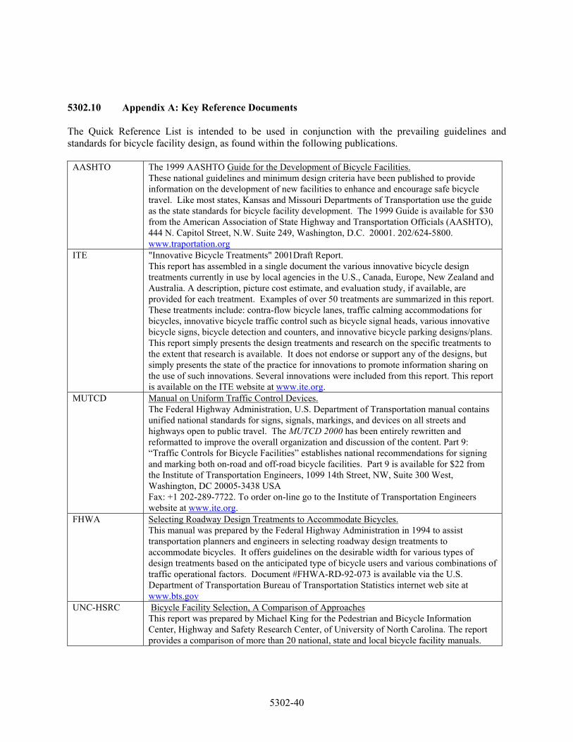
5302.10 Appendix A: Key Reference Documents The Quick Reference List is intended to be used in conjunction with the prevailing guidelines and standards for bicycle facility design, as found within the following publications.
AASHTO The 1999 AASHTO Guide for the Development of Bicycle Facilities. These national guidelines and minimum design criteria have been published to provide information on the development of new facilities to enhance and encourage safe bicycle travel. Like most states, Kansas and Missouri Departments of Transportation use the guide as the state standards for bicycle facility development. The 1999 Guide is available for $30 from the American Association of State Highway and Transportation Officials (AASHTO), 444 N. Capitol Street, N.W. Suite 249, Washington, D.C. 20001. 202/624-5800. www.traportation.org
ITE "Innovative Bicycle Treatments" 2001Draft Report. This report has assembled in a single document the various innovative bicycle design treatments currently in use by local agencies in the U.S., Canada, Europe, New Zealand and Australia. A description, picture cost estimate, and evaluation study, if available, are provided for each treatment. Examples of over 50 treatments are summarized in this report. These treatments include: contra-flow bicycle lanes, traffic calming accommodations for bicycles, innovative bicycle traffic control such as bicycle signal heads, various innovative bicycle signs, bicycle detection and counters, and innovative bicycle parking designs/plans. This report simply presents the design treatments and research on the specific treatments to the extent that research is available. It does not endorse or support any of the designs, but simply presents the state of the practice for innovations to promote information sharing on the use of such innovations. Several innovations were included from this report. This report is available on the ITE website at www.ite.org.
MUTCD Manual on Uniform Traffic Control Devices. The Federal Highway Administration, U.S. Department of Transportation manual contains unified national standards for signs, signals, markings, and devices on all streets and highways open to public travel. The MUTCD 2000 has been entirely rewritten and reformatted to improve the overall organization and discussion of the content. Part 9: “Traffic Controls for Bicycle Facilities” establishes national recommendations for signing and marking both on-road and off-road bicycle facilities. Part 9 is available for $22 from the Institute of Transportation Engineers, 1099 14th Street, NW, Suite 300 West, Washington, DC 20005-3438 USA Fax: +1 202-289-7722. To order on-line go to the Institute of Transportation Engineers website at www.ite.org.
FHWA Selecting Roadway Design Treatments to Accommodate Bicycles. This manual was prepared by the Federal Highway Administration in 1994 to assist transportation planners and engineers in selecting roadway design treatments to accommodate bicycles. It offers guidelines on the desirable width for various types of design treatments based on the anticipated type of bicycle users and various combinations of traffic operational factors. Document #FHWA-RD-92-073 is available via the U.S. Department of Transportation Bureau of Transportation Statistics internet web site at www.bts.gov
UNC-HSRC Bicycle Facility Selection, A Comparison of Approaches This report was prepared by Michael King for the Pedestrian and Bicycle Information Center, Highway and Safety Research Center, of University of North Carolina. The report provides a comparison of more than 20 national, state and local bicycle facility manuals.
5302-40

5302.11 Appendix B: Quick Reference Guide The following quick reference guide has been assembled to assist local professionals in planning and designing bicycle facilities in the Kansas City region The listing is intended to serve as a convenient reference point for applicable standards and guidelines pertaining to various elements of bicycle projects. The list contains both references to this document and external documents listed in Appendix A. For comprehensive guidance and specific interpretation, the user is referred to detailed discussions located within the other publications, as identified below. Table 1. Quick Reference Guide
Item Notes Source Page Drainage Grates Do not use a parallel-bar grate AASHTO p. 18 Pavement markings for obstructions
THIS DOCUMENT p. 5,6
MUTCD p.9C-7 Railroad Crossings Crossing angle ideally, cross at 90 degree angle AASHTO p. 60 Widen travel way if <45 degree angle THIS DOCUMENT p. 6 Warning signs 115 feet min. before crossing MUTCD p.9B.18 Pavement markings 65 feet min. before crossing MUTCD p. 9B.18 Traffic Control Devices Bicycle detectors diagonal quadruple loops For shared use roadways; Quadruple loops for bicycle lanes THIS DOCUMENT p.7 Video Camera THIS DOCUMENT p.7 RTMS THIS DOCUMENT p.8 Push Button THIS DOCUMENT p.9 Clearance interval Bicycle speed of 10 mph with AASHTO p. 64 3.0 – 6.0 sec. clearance time Signage Lateral placement 3 feet min./6 feet max. MUTCD p.9B-1 Height 4 feet min/5 feet max MUTCD p.9B-1 Maintenance Practices Bikeway standards Same or greater maintenance AASHTO p. 73 standard than vehicular travel way Adequate maintenance THIS DOCUMENT p.10 Paved Shoulders General purpose/application THIS DOCUMENT p. 11-13 Roadway cross sections THIS DOCUMENT p. 46 Shoulder Width At 35 mph 4 feet min. AASHTO p.16 At speeds >35 mph > 4 feet At speeds >50 mph 5’ and 5’ with guardrail or other Roadside barrier As dependent on vehicular volumes and speeds FHWA p. 16-21 Wide Curb Lanes General purpose/application THIS DOCUMENT p. 15,16 Roadway cross sections THIS DOCUMENT p. 46
5302-41
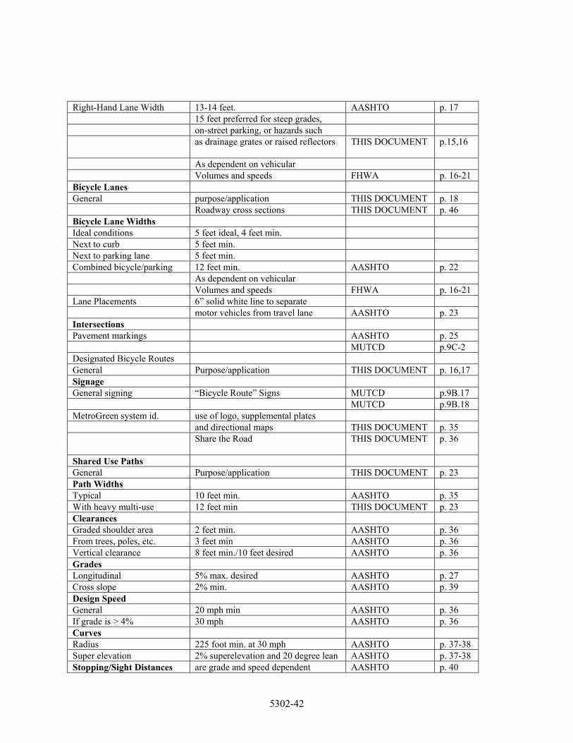
Right-Hand Lane Width 13-14 feet. AASHTO p. 17 15 feet preferred for steep grades, on-street parking, or hazards such as drainage grates or raised reflectors THIS DOCUMENT
p.15,16
As dependent on vehicular Volumes and speeds FHWA p. 16-21 Bicycle Lanes General purpose/application THIS DOCUMENT p. 18 Roadway cross sections THIS DOCUMENT p. 46 Bicycle Lane Widths Ideal conditions 5 feet ideal, 4 feet min. Next to curb 5 feet min. Next to parking lane 5 feet min. Combined bicycle/parking 12 feet min. AASHTO p. 22 As dependent on vehicular Volumes and speeds FHWA p. 16-21 Lane Placements 6” solid white line to separate motor vehicles from travel lane AASHTO p. 23 Intersections Pavement markings AASHTO p. 25 MUTCD p.9C-2 Designated Bicycle Routes General Purpose/application THIS DOCUMENT p. 16,17 Signage General signing “Bicycle Route” Signs MUTCD p.9B.17 MUTCD p.9B.18 MetroGreen system id. use of logo, supplemental plates and directional maps THIS DOCUMENT p. 35 Share the Road THIS DOCUMENT
p. 36
Shared Use Paths General Purpose/application THIS DOCUMENT p. 23 Path Widths Typical 10 feet min. AASHTO p. 35 With heavy multi-use 12 feet min THIS DOCUMENT p. 23 Clearances Graded shoulder area 2 feet min. AASHTO p. 36 From trees, poles, etc. 3 feet min AASHTO p. 36 Vertical clearance 8 feet min./10 feet desired AASHTO p. 36 Grades Longitudinal 5% max. desired AASHTO p. 27 Cross slope 2% min. AASHTO p. 39 Design Speed General 20 mph min AASHTO p. 36 If grade is > 4% 30 mph AASHTO p. 36 Curves Radius 225 foot min. at 30 mph AASHTO p. 37-38 Super elevation 2% superelevation and 20 degree lean AASHTO p. 37-38 Stopping/Sight Distances are grade and speed dependent AASHTO p. 40
5302-42
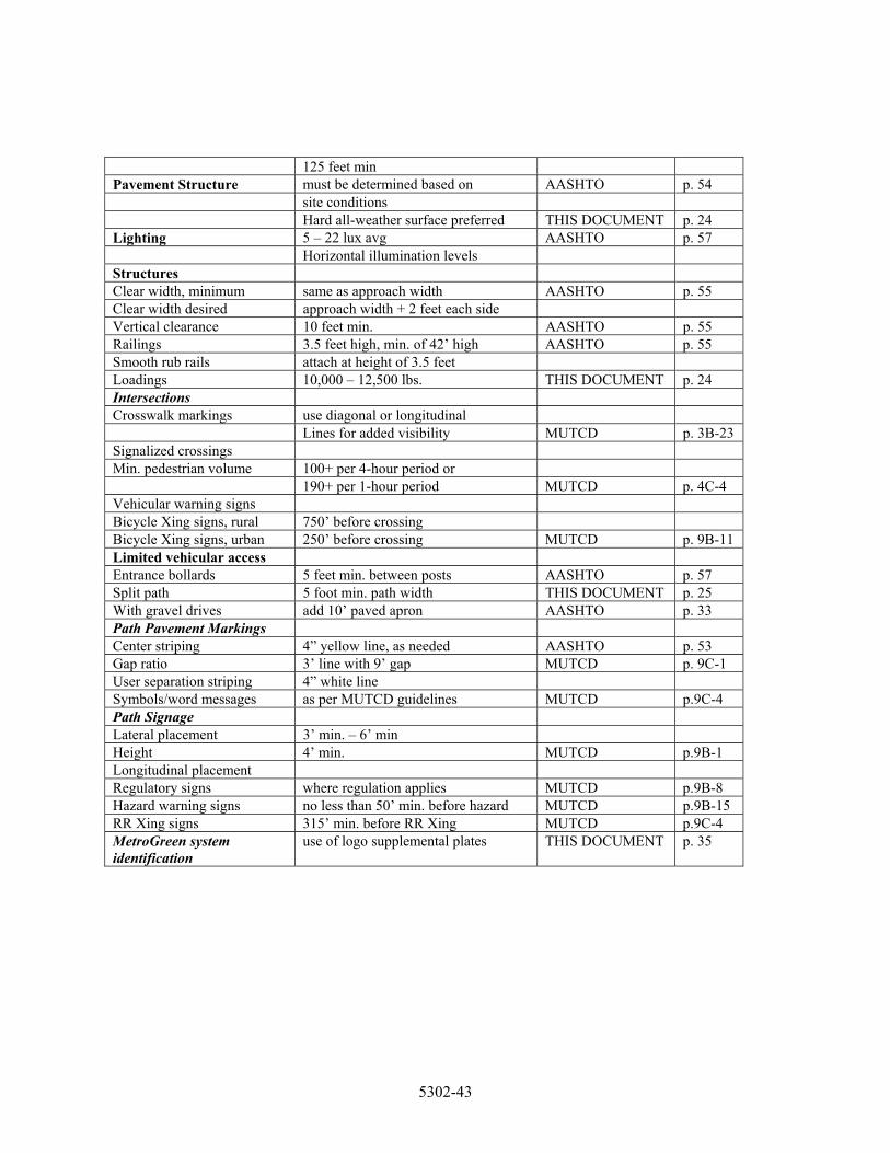
125 feet min Pavement Structure must be determined based on AASHTO p. 54 site conditions Hard all-weather surface preferred THIS DOCUMENT p. 24 Lighting 5 – 22 lux avg AASHTO p. 57 Horizontal illumination levels Structures Clear width, minimum same as approach width AASHTO p. 55 Clear width desired approach width + 2 feet each side Vertical clearance 10 feet min. AASHTO p. 55 Railings 3.5 feet high, min. of 42’ high AASHTO p. 55 Smooth rub rails attach at height of 3.5 feet Loadings 10,000 – 12,500 lbs. THIS DOCUMENT p. 24 Intersections Crosswalk markings use diagonal or longitudinal Lines for added visibility MUTCD p. 3B-23 Signalized crossings Min. pedestrian volume 100+ per 4-hour period or 190+ per 1-hour period MUTCD p. 4C-4 Vehicular warning signs Bicycle Xing signs, rural 750’ before crossing Bicycle Xing signs, urban 250’ before crossing MUTCD p. 9B-11 Limited vehicular access Entrance bollards 5 feet min. between posts AASHTO p. 57 Split path 5 foot min. path width THIS DOCUMENT p. 25 With gravel drives add 10’ paved apron AASHTO p. 33 Path Pavement Markings Center striping 4” yellow line, as needed AASHTO p. 53 Gap ratio 3’ line with 9’ gap MUTCD p. 9C-1 User separation striping 4” white line Symbols/word messages as per MUTCD guidelines MUTCD p.9C-4 Path Signage Lateral placement 3’ min. – 6’ min Height 4’ min. MUTCD p.9B-1 Longitudinal placement Regulatory signs where regulation applies MUTCD p.9B-8 Hazard warning signs no less than 50’ min. before hazard MUTCD p.9B-15 RR Xing signs 315’ min. before RR Xing MUTCD p.9C-4 MetroGreen system identification
use of logo supplemental plates THIS DOCUMENT p. 35
5302-43
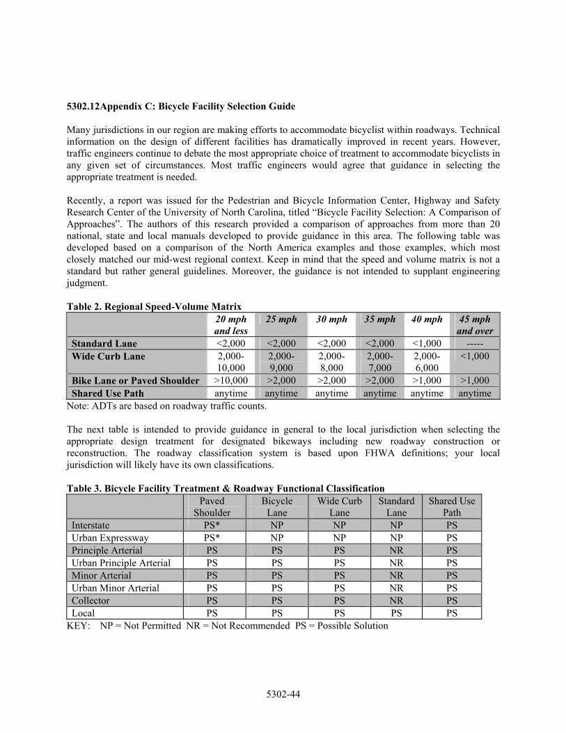
5302.12 Appendix C: Bicycle Facility Selection Guide Many jurisdictions in our region are making efforts to accommodate bicyclist within roadways. Technical information on the design of different facilities has dramatically improved in recent years. However, traffic engineers continue to debate the most appropriate choice of treatment to accommodate bicyclists in any given set of circumstances. Most traffic engineers would agree that guidance in selecting the appropriate treatment is needed. Recently, a report was issued for the Pedestrian and Bicycle Information Center, Highway and Safety Research Center of the University of North Carolina, titled “Bicycle Facility Selection: A Comparison of Approaches”. The authors of this research provided a comparison of approaches from more than 20 national, state and local manuals developed to provide guidance in this area. The following table was developed based on a comparison of the North America examples and those examples, which most closely matched our mid-west regional context. Keep in mind that the speed and volume matrix is not a standard but rather general guidelines. Moreover, the guidance is not intended to supplant engineering judgment. Table 2. Regional Speed-Volume Matrix 20 mph
and less 25 mph 30 mph 35 mph 40 mph 45 mph
and over Standard Lane <2,000 <2,000 <2,000 <2,000 <1,000 ----- Wide Curb Lane 2,000-
10,000 2,000-9,000
2,000-8,000
2,000-7,000
2,000-6,000
<1,000
Bike Lane or Paved Shoulder >10,000 >2,000 >2,000 >2,000 >1,000 >1,000 Shared Use Path anytime anytime anytime anytime anytime anytime
Note: ADTs are based on roadway traffic counts. The next table is intended to provide guidance in general to the local jurisdiction when selecting the appropriate design treatment for designated bikeways including new roadway construction or reconstruction. The roadway classification system is based upon FHWA definitions; your local jurisdiction will likely have its own classifications. Table 3. Bicycle Facility Treatment & Roadway Functional Classification
Paved Shoulder
Bicycle Lane
Wide Curb Lane
Standard Lane
Shared Use Path
Interstate PS* NP NP NP PS Urban Expressway PS* NP NP NP PS Principle Arterial PS PS PS NR PS Urban Principle Arterial PS PS PS NR PS Minor Arterial PS PS PS NR PS Urban Minor Arterial PS PS PS NR PS Collector PS PS PS NR PS Local PS PS PS PS PS
KEY: NP = Not Permitted NR = Not Recommended PS = Possible Solution
5302-44

NOTE: An asterisk (*) indicates that this solution may be considered when all other reasonable alternatives treatments are not practical and routing is necessary to provide continuity of bicycle routes. An example of this would be major river bridges (such as the Heart of America Bridge over the Missouri River).
5302-45
5302.13 Appendix D: Bikeway Facility Cross-Section The Kansas City Metropolitan Chapter of the American Public Works Association has developed a series of “Street Section Details” to accommodate bicycle vehicular traffic. Where bicycles are expected or along corridors that that a local jurisdiction has identified in a planned bikeway network the following street sections are recommended at a minimum.
SEE Street_sections.pdf
5302-46
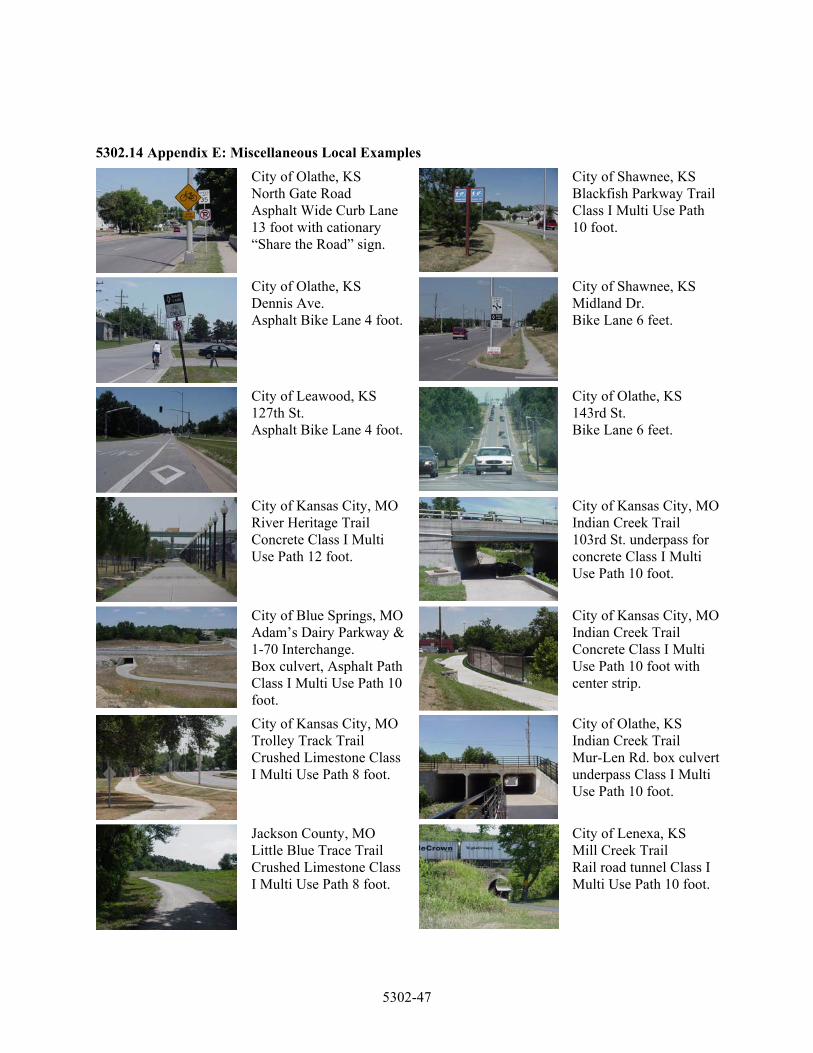
5302.14 Appendix E: Miscellaneous Local Examples
City of Olathe, KS North Gate Road Asphalt Wide Curb Lane 13 foot with cationary “Share the Road” sign.
City of Shawnee, KS Blackfish Parkway Trail Class I Multi Use Path 10 foot.
City of Olathe, KS Dennis Ave. Asphalt Bike Lane 4 foot.
City of Shawnee, KS Midland Dr. Bike Lane 6 feet.
City of Leawood, KS 127th St. Asphalt Bike Lane 4 foot.
City of Olathe, KS 143rd St. Bike Lane 6 feet.
City of Kansas City, MO River Heritage Trail Concrete Class I Multi Use Path 12 foot.
City of Kansas City, MO Indian Creek Trail 103rd St. underpass for concrete Class I Multi Use Path 10 foot.
City of Blue Springs, MO Adam’s Dairy Parkway & 1-70 Interchange. Box culvert, Asphalt Path Class I Multi Use Path 10 foot.
City of Kansas City, MO Indian Creek Trail Concrete Class I Multi Use Path 10 foot with center strip.
City of Kansas City, MO Trolley Track Trail Crushed Limestone Class I Multi Use Path 8 foot.
City of Olathe, KS Indian Creek Trail Mur-Len Rd. box culvert underpass Class I Multi Use Path 10 foot.
Jackson County, MO Little Blue Trace Trail Crushed Limestone Class I Multi Use Path 8 foot.
City of Lenexa, KS Mill Creek Trail Rail road tunnel Class I Multi Use Path 10 foot.
5302-47