Embed Size (px)
Citation preview

Discontinuous Galerkin methods for plasma physics in the scrape-off
layer of tokamaks
C. MichoskiX ? †, D. Meyerson‡, T. Isaac?, F. Waelbroeck‡,Institute for Fusion Studies (IFS)‡, Department of Physics‡
Institute for Computational Engineering and Sciences (ICES)?,
Department of Aerospace Engineering and Engineering Mechanics†
University of Texas at Austin, Austin, TX 78712
Abstract
A new parallel discontinuous Galerkin solver, called ArcOn, is developed to describe the inter-mittent turbulent transport of filamentary blobs in the scrape-off layer (SOL) of fusion plasma.The model is comprised of an elliptic subsystem coupled to two convection-dominated reaction-diffusion-convection equations. Upwinding is used for a class of numerical fluxes developed to ac-commodate cross product driven convection, and the elliptic solver uses SIPG, NIPG, IIPG, Brezzi,and Bassi-Rebay fluxes to formulate the stiffness matrix. A novel entropy sensor is developed forthis system, designed for a space-time varying artificial diffusion/viscosity regularization algorithm.Some numerical experiments are performed to show convergence order on manufactured solutions,regularization of blob/streamer dynamics in the SOL given unstable parameterizations, long-timestability of modon (or dipole drift vortex) solutions arising in simulations of drift-wave turbulence,and finally the formation of edge mode turbulence in the scrape-off layer under turbulent saturationconditions.
Keywords: Nodal/modal, discontinuous Galerkin, unified formulation, elliptic, hyperbolic, parabolic,plasma physics, fusion, tokamaks, verification, blobs, modons, scrape-off layer, interior penalty, turbulence,upwinding, artificial diffusion, massively parallel.
Contents
§1 Introduction 2
§2 The governing equations 4
§3 The discretization procedure 5
3.1 The approximation procedure . . . . . . . . . . . . . . . . . . . . . . . . . . . . . . . . . 6
3.1.1 The continuity equation . . . . . . . . . . . . . . . . . . . . . . . . . . . . . . . . 6
3.1.2 The ion polarization . . . . . . . . . . . . . . . . . . . . . . . . . . . . . . . . . . 7
3.1.3 The convective fluxes . . . . . . . . . . . . . . . . . . . . . . . . . . . . . . . . . . 7
3.1.4 The elliptic subsystems . . . . . . . . . . . . . . . . . . . . . . . . . . . . . . . . 9
3.2 The formulation . . . . . . . . . . . . . . . . . . . . . . . . . . . . . . . . . . . . . . . . 11
XCorresponding author, †[email protected]
1

2 DG methods for plasma physics in the scrape-off layer of tokamaks
§4 Numerical tests 12
4.1 Elliptic verification . . . . . . . . . . . . . . . . . . . . . . . . . . . . . . . . . . . . . . . 13
4.2 Hyperbolic-parabolic verification . . . . . . . . . . . . . . . . . . . . . . . . . . . . . . . 13
4.3 Streamer validation . . . . . . . . . . . . . . . . . . . . . . . . . . . . . . . . . . . . . . 16
§5 Regularization processes 18
5.1 Artificial diffusion and gradient driven flow . . . . . . . . . . . . . . . . . . . . . . . . . 18
§6 Physical solutions 22
6.1 Modon solutions . . . . . . . . . . . . . . . . . . . . . . . . . . . . . . . . . . . . . . . . 22
6.2 Turbulence . . . . . . . . . . . . . . . . . . . . . . . . . . . . . . . . . . . . . . . . . . . 25
§7 Conclusion 27
§8 Acknowledgements 28
§1 Introduction
In magnetic fusion devices, a large fraction of the thermal power flows to an actively cooled strike-plate through a narrow layer called the scrape-off layer (SOL) [44]. This layer lies at the boundarybetween closed field lines and field lines that connect to the wall, and its width is determined by thecompetition between the turbulent transport across the magnetic field and the very rapid transportalong the field. This width determines the heat flux density on the wall and impacts wall erosion,recycling, and density control. Transport in the SOL is known to be highly intermittent and dominatedby the ejection of coherent plasma filaments known as“blobs”or“streamers” [22, 35, 64]. The modelingof this turbulent transport is important in order to predict and understand the dependence of the SOLwidth on the plasma parameters and machine size.
The equations that govern SOL blob dynamics have been formulated and analyzed [5, 26, 35, 62],but many questions remain open. From a mathematical point of view the dynamics of existing SOLplasma models can be characterized as systems of equations that are driven by operators that arenonlinear and contain multiple signatures (e.g. elliptic, parabolic, dispersive, hyperbolic operators,etc.) displaying weak regularity features in the coupling. As the consistency, stability, and accuracyof numeric methods are strongly constrained by the behavior of the underlying mathematical models,the difficulties posed by these complicated SOL plasma dynamics raise interesting and challengingtechnical questions.
As a potential solution to the difficulties that can arise, we explore the use of a discontinuousGalerkin (DG) finite element method for modeling blob dynamics in the SOL. The discontinuousGalerkin method is a high order numerical method, that has been found to provide formidable accuracy,stability, and robustness in many areas of nonlinear dynamics [15, 16, 25, 37]. Moreover, DG methodsare unified in the sense that they are well-suited for rigorous analysis of both the physics as well as thenumerics and mathematics of the system. They demonstrate high order convergence rates [2, 4], arewell-established as candidates for computationally optimal adaptive technologies (e.g. hp-adaptivityand r-adaptivity) [21, 52], are extremely scalable (especially on state-of-the-art architectures withhigh thread parallel arithmetic intensity, such as GPUs and coprocessors) [1, 34, 73, 75], and areoften noted as being remarkably flexible for accurately modeling large categories of coupled systems of

§1 Introduction 3
initial-boundary value problems with strongly nonlinear forcings. This aspect of DG methods makesthem particularly appealing for studying scrape-off layer dynamics, as the system of PDEs in questionin the scrape-off layer is often highly variable, requires great flexibility in representation, possess weakregularity features, and may involve complicated geometries (e.g. in the presence of magnetic chaos)with nonlinear boundary forcings that are befitting to finite element methods in general.
The application of DG methods to problems arising in plasma physics and nuclear engineeringhave established a high benchmark. Dawson, Wheeler and Proft studied neutron transport in [20].In [31, 32] Hesthaven and Jacobs addressed DG plasma building block models, along with providinghigh resolution insight into the basic aspects of applying DG methods to plasma problems. Warburtonand Karniadakis developed a turbulent DNS solver for unsteady viscous MHD in [72], and Cheng, Li,Qiu, and Xu [14] have recently studied specialized positivity preserving DG methods in the contextof ideal MHD. In plasma kinetic theory, Heath, Gamba, Morrison, Cheng, and Michler [13, 28] havedeveloped some impressive high dimensional Vlasov-Poisson schemes, where Rossmanith and Seal havesimilarly implemented DG schemes for Vlasov-Poisson, though in the Semi-Lagrangian setting [61].Edge turbulence models have recently worked their way into some studies of Peterson and Hammet[59],while some of the most well-established DG results in computational plasma physics are those from themultifluid models of Shumlak, Loverich, Hakim, Srinivasan, and Meier et al. [45, 46, 48, 67, 68], whichhave not only been thoroughly validated, but thoroughly benchmarked against established codes inthe community.
The present paper represents an interdisciplinary effort to apply general discontinuous Galerkinmethods to the modeling of plasma dynamics in tokamak scrape-off layers. This work draws heavilyfrom a number of disciplines, in the context of trying to serve as a powerful staging ground for furtherand deeper analysis of tokamak reactors. In this direction, the code architecture we have developedfor this study has been given the moniker ArcOn. The code itself is explicit in time and consists ofthree coupled equations that require two local discontinuous solves, and a global linear solve in theelliptic subsystem (to be described below). It has been written (primarily) in C++, and utilizes anumber of external libraries, including: deal.II [7], p4est [12], and PETSc [6]. The development ofArcOn has required the modification of deal.II, which required a fundamental update/extension tocore functionality in order to provide inter-software support for periodic boundary data over massivelyparallel distributed meshes. We mention this process briefly here, as it was quite time-consuming andintroduced a nontrivial technical challenge in the computer science aspect of the code development.These modifications were performed in consultation with project leaders, and have subsequently beenopenly distributed to their respective communities for broad use.
All computations below were run in parallel on the Texas Advanced Computing Center’s (TACC’s)10 PetaFLOPS Dell Linux Cluster based Stampede system, comprised of 6,400+ Dell PowerEdgeserver nodes, each outfitted with 2 Intel Xeon E5 (Sandy Bridge) processors and an Intel Xeon PhiCoprocessor (MIC Architecture). For this study, relatively small meshes were used at low polynomialorder, that ranged from tens of thousands of degrees of freedom, to tens of millions. All runs wereperformed in parallel on between 16 to 256 cores.
An outline of the paper is as follows. In section 2 we present the physics-based SOL model forfilamentary blob transport. Here we provide motivation for the system formulation, and heuristicallydiscuss its features, scope, and limitations. In section 3 we review the formulation of the discontinuousGalerkin method applied to the mathematical model presented in section 2. We address some salientfeatures of ArcOn, including the ability to use both multiple solvers (e.g. SIPG, NIPG, etc.) andvarious basis functions, including both nodal and modal finite elements. We also describe the upwind-

4 DG methods for plasma physics in the scrape-off layer of tokamaks
ing flux schemes used in the approximate Riemann-type solvers, and the strong stability preservingtemporal discretization scheme employed. In section 4 we discuss the parameters of a classical verifi-cation study by way of a manufactured solution, and perform numerical experiments that demonstratethe optimal (to super-optimal in places) convergence order in each operator subsystem of ArcOn. Insection 5 we discuss some of the basic stability features of the DG method, and how regularizationprocedures can be used to ensure numerical stability. We present here a basic blob example adjoined toa new artificial diffusion scheme, and run using a CFL-based variable timestepping algorithm. Finallyin section 6 we show a modon solution to the physics of the system, briefly analyze and vlaidate someof the cogent numerical properties of blobs, and demonstrate the effectiveness of ArcOn in solvingturbulent plasma dynamics at saturation..
§2 The governing equations
We use a two-dimensional model for the SOL turbulence that describes the evolution of the densityn, the vorticity U , and the electrostatic potential φ. The latter plays the role of a stream-functionfor the ion velocity, which is given by the perpendicular E ×B drift velocity VE×B ∼ b ×∇φ (hereb = B/B and E = −∇φ is the electric field). The ez direction is chosen to lie along the magnetic field,ez = b. The model is based on the assumption that due to rapid transport along the magnetic field,the quantities of interest have negligible variation in the z direction except at the boundary betweenthe plasma and the wall where sheath physics enters the equations as a sink term. The coordinatealong the normal to the plasma surface is denoted by x, and the coordinate in the binormal direction(perpendicular to both ex and the magnetic field) is denoted by y. The model equations are solvedusing the variables (x, y, t) ∈ Ω × (0, T ), where Ω is a domain of the (x, y) plane extending over theSOL in the x direction. The spatial units are normalized relative to a ratio of the ion acoustic speedcs and the ion gyrofrequency ωci, given in terms of the Bohm gyro-radius ρcs. The equations are
∂tn+ [φ, n] = −α0n+D∇2⊥n, n|t=0 = n0, n = nb on ∂Ω, (2.1)
∂tU + [φ,U ] = αφ− β[x, lnn] + µ∇2⊥U, U |t=0 = U0, U = Ub on ∂Ω, (2.2)
U = ∇2⊥φ, φ|t=0 = φ0, φ = φb on ∂Ω, (2.3)
corresponding to the continuity, vorticity and Poisson equations respectively. The brackets are definedfor scalar-valued functions a and b by, [a, b] = ez · (∇⊥a×∇⊥b). The left-hand sides of (2.1) and (2.2)represents the convective derivative with respect to the ion fluid. We will also use ∇⊥ ·∇⊥ = ∇2
⊥ = ∆⊥frequently throughout to represent orthogonal operators. In addition, we will frequently represent ourcoordinate chart by pairs in vector form, x = (x, y).
The first equation (2.1) indicates mass conservation of the plasma density n = n(x, t). Theplasma (mass) diffusion on the right is driven by the diffusion coefficient D. The reaction-type termα0n represents the competition between ionization sourcing and parallel loss at the wall, with α0 ∼(kα − L‖/cs), where L‖ is the parallel length from the mid-plane to the wall and cs the ion-acousticspeed.
The second equation (2.2) is frequently referred to as a conservation equation for the vorticityU = U(x, t). Note that the vorticity variable U is introduced for the sake of clarity, so as to separatethe elliptic equation (2.3) and the dynamic equation (2.2) into two well-defined mathematical subsys-tems that will be treated individually in our numerical methods. The vorticity, up to a rescaling, is

§3 The discretization procedure 5
determined by the electric field potential φ = φ(x, t), leading to the Boussinesq approximation in theion polarization term,
∇ · DDt
(nMc2
B2∇⊥φ
)∝ ∂tU + [φ,U ], (2.4)
where M is the ion mass, and c is the speed of light. The term proportional to β represents the effectsof ∇B (caused by toroidal curvature) on the system dynamics. Lastly, the term proportional to µ canbe viewed as a manifestation of classical viscosity, though in practice its magnitude is generally chosenso that it serves as a numerical regularization term [26, 35].
Below we will occasionally make the implicit assumption that β is a linear function of n, β = Cnfor C a constant, such that the leading n−1 term can be dropped, leading to a stabilized form aboutthe vacuum, n ≈ 0 (though this instability can always be removed through a basic rescaling argument,as presented in section 6).
§3 The discretization procedure
Let us discretize our spatial domain Ω. Consider the open set Ω ⊂ R2 with physical boundary ∂Ω,given T > 0 such that QT = Ω × (0, T ). Let Th denote the partition of the closure of the polygonalmesh of Ω, which we denote Ωh, into a finite number of polygonal elements denoted Ωe, such thatTh = Ωe1 ,Ωe2 , . . . ,Ωene, for ne ∈ N the number of elements in Ωh. Here and below the meshdiameter h is chosen to satisfy h = minij(dij) for the distance function dij = d(xi,xj) and elementwiseface vertices xi,xj ∈ ∂Ωe when the mesh is structured and regular. For unstructured or irregularmeshes we provide a range over the mesh.
Now, let Γij denote the face shared by two neighboring elements Ωei and Ωej , and for i ∈ I ⊂Z+ = 1, 2, . . . define the indexing set r(i) = j ∈ I : Ωej is a neighbor of Ωei. Let us denote all Ωei
containing the boundary ∂Ωh by Sj and letting IB ⊂ Z− = −1,−2, . . . define s(i) = j ∈ IB : Sj isa face of Ωei such that Γij = Sj for Ωei ∈ Ωh when Sj ∈ ∂Ωei , j ∈ IB. Then for Ξi = r(i) ∪ s(i), wehave
∂Ωei =⋃
j∈Ξ(i)
Γij , and ∂Ωei ∩ ∂Ωh =⋃j∈s(i)
Γij .
We are interested in obtaining an approximate solution to (2.1)-(2.3) at time t on the finite dimen-sional space of piecewise polynomial functions over Ω restricted to Th, given as
Sph(Ωh,Th) = v : v|Ωei∈Pp(Ωei) ∀Ωei ∈ Th
for Pp(Ωei) the space of degree of (at most) p polynomials over Ωei .
Choosing a set of basis functions Nl for l = 0, . . . , np the corresponding degrees of freedom indexedby the (spatial) spectral order p of the local element, we can denote the three local solutions in themodal basis over a finite element cell Ωei as
nihp(t,x) =
np∑l=0
nil(t)Nil (x), and U ihp(t,x) =
np∑l=0
U il (t)Nil (x), ∀ x ∈ Ωei ,
φihp(t,x) =
np∑l=0
φil(t)Nil (x), ∀ x ∈ Ωei ,

6 DG methods for plasma physics in the scrape-off layer of tokamaks
where the N il ’s are the finite element shape functions. Let us consider j arbitrary finite dimensional
test functions ζj characterized by
ζij(x) =
np∑l=0
ζilNil (x), ∀ (x) ∈ Ωei ,
where ζij are the modal coordinates in each Ωei . These functions are chosen as members of the brokenSobolev space over the partition Th defined by
W k,q(Ωh,Th) = ω : ω|Ωei∈W k,q(Ωei) ∀Ωei ∈ Th.
In particular, when q = 2 and k = 0 we have the standard L2-norm, such that ζj ∈ L2loc with piecewise
polynomials representations ζij ∈ Sph(Ωh,Th). For the d-dimensional vector basis (in our case the spatial
dimension dim = d = 2) we will denote the j arbitrary finite dimensional test functions ξj characterizedas the direct product space, such that in the usual sense, when ζj ∈ L2 with piecewise polynomialsζij ∈ S
ph(Ωh,Th), this implies that ξj ∈ [L2]2 with piecewise polynomials ξij ∈ [Sph(Ωh,Th)]2, and so on.
We can equivalently recast the modal discontinuous Galerkin solution into the nodal basis (i.e. thenodal discontinuous Galerkin solution), by choosing np support points in each finite element cell,
V ihp(t,x) =
np∑l=0
V il(t)ζ
il (x) =
np∑`=0
V i`(x
i`, t)ϕ
i`(x), ∀ x ∈ Ωei ,
for nodal basis ϕi`. It should be observed that the nodal and modal solutions are not equivalent, asdiscussed in detail in [30]. We also note that ArcOn at present supports 19 different basis functions,including discontinuous tensor products of Legendre polynomials, Lagrange nodal polynomials, etc.
3.1 The approximation procedure
Next we recast (2.1)–(2.3) in the auxiliary mixed formulation, as satisfying the six simultaneous equa-tions
∂tn+ [φ, n] = −αn+D∇⊥ · O, O = ∇⊥n, (3.1)
∂tU + [φ,U ] = αφ− β[x, lnn] + µ∇⊥ ·U , U = ∇⊥U, (3.2)
∇⊥ ·E⊥ = U, E⊥ = ∇⊥φ, (3.3)
where we note that substitutions can be made in terms of the “auxiliary variables” O,U ,E⊥.
3.1.1 The continuity equation
In order to recover the weak (or variational) form for the finite element solution, we multiply eachequation by a different finite element test function ζ and integrate by parts. Thus the coupled equationsof (6.2) become the pair
d
dt
∫Ωei
nζi1dxdy =
∫∂Ωei
DOζi1 · ndxdy −∫
Ωei
ζi1 (∇⊥φ×∇⊥n) dxdy
−∫
Ωei
αnζi1dxdy −∫
Ωei
DO∇⊥ζi1dxdy,∫Ωei
O · ξi1dxdy =
∫∂Ωei
nξi1 · ndxdy −∫
Ωei
n∇⊥ · ξi1dxdy.
(3.4)

§3 The discretization procedure 7
This variational formulation is then projected into the discrete discontinuous space. The massdiffusion terms on the RHS of (3.4) are solved using the unified mixed method form for elliptic andparabolic solutions to PDEs [2, 4, 60], where we denote the boundary term by Di(O i
hp, nihp, ζ
i1). In
this generalized setting we are able to select from a large collection of diffusive numerical fluxes,such as the local discontinuous Galerkin flux (LDG), the interior penalty Galerkin flux (IPG), thesymmetric interior penalty Galerkin flux (SIPG), and the nonsymmetric interior penalty Galerkin flux(NIPG), etc. Effectively this reduces to selecting a particular type of numerical behavior that relatesto stability, consistency, and convergence properties of the numerical solution, which will be discussedin more detail below. The auxiliary equation in (3.4) is formatted in essentially the same way, wherehere the boundary flux is represented by Ni(n
ihp, ξ
i1).
3.1.2 The ion polarization
The variational form of the vorticity equation (6.3) is almost the same, but with the addition of thecurvature term:
d
dt
∫Ωei
ζi2Udxdy = −∫
Ωei
ζi2 (∇⊥φ×∇⊥U) dxdy −∫
Ωei
ζi2β(∇⊥x× n−1∇⊥n
)dxdy
+
∫Ωei
ζi2αφdxdy +
∫∂Ωei
ζi2µU · ndxdy −∫
Ωei
µU ∇⊥ζi2dxdy,∫Ωei
ξi2 ·U dxdy =
∫∂Ωei
ξi2 · Undxdy −∫
Ωei
U∇⊥ · ξi2dxdy,
(3.5)
where again the cross products in the ion polarization term represent the same choices as those givenabove.
As above with the continuity equation, we now project the weak formulation into the piecewisepolynomial representation space. The diffusive terms of (3.5) are solved in the same way as thosein (3.4), where Mi(U i
hp, φihp, ζ
i2) represents the diffusive boundary term, and the auxiliary numerical
boundary term is given by Qi.
3.1.3 The convective fluxes
The convective fluxes for this system demonstrate some unique difficulties in comparison to thosepresented by standard divergence form flux-based solvers. Namely, the bracketed term is a crossproduct of gradients that has no exact algebraic divergence form Jacobian. That is, even though forexample [a, b] = ∇ · (aez × ∇b), the arguments to the divergence operator are differential and notalgebraic. Hence the usual Jacobian matrix of the term is different than those often encountered incomputational fluid dynamics, where standard implementations of Riemann solvers such as Roe orLax-Friedrichs are straight forward to implement. These bracketed fluxes are however, quite commonin plasma physics, and thus must be addressed. We do so here by applying a standard upwindingapproach to each equation separately, thus inducing a slightly weaker coupling than the some commonRiemann solvers (e.g. the Roe solver). It remains an open question what flux formulation might beused to strengthen this coupling, but in this direction we point the reader to the potential of usingcosymplectic forms [56] to tensorialize the flux Jacobian into an eigenproblem.

8 DG methods for plasma physics in the scrape-off layer of tokamaks
To form our upwinding scheme, we first notice that expanding the cross product term of the massequation generates twisted mixed partials,
−∫
Ωei
ζi1 (∇⊥φ×∇⊥n) dxdy = −∫
Ωei
ζi1∂φ
∂x
∂n
∂ydxdy +
∫Ωei
ζi1∂n
∂x
∂φ
∂ydxdy. (3.6)
that drives the convective transport of the density.A naive coupling can be chosen that simply linearizes the solution relative to the auxiliary terms,
corresponding to an electric field E⊥ = ∇⊥φ = (Ex, Ey) and density gradient O = (Ox,Oy), such that(3.6) can be written as
The quasistrong flux :∫
Ωeiζi1 (∇⊥φ×∇⊥n) dxdy =
∫Ωei
ζi1 (E⊥ × O) dxdy. (3.7)
This form of (3.6) is characterized as a quasistrong linearization as it forces the convective transportthrough the diffusive fluxes, as can be seen more explicitly below.
An alternative to (3.7) is to expand (3.6) into a stronger form, by rebalancing the components of(3.6) across the boundary terms, thus inducing a proper convective flux as:
The strong flux :
−∫
Ωeiζ2∂φ∂x
∂n∂y dxdy = −1
2
∫∂Ωei
ζ2φOynxdxdy + 12
∫Ωei
φOy∂ζ2∂x dxdy
−12
∫∂Ωei
ζ2nExnydxdy + 12
∫Ωei
nEx∂ζ2∂y dxdy,∫
Ωeiζ2∂n∂x
∂φ∂y dxdy = 1
2
∫∂Ωei
ζ2φOxnydxdy − 12
∫Ωei
φOx∂ζ2∂y dxdy
+12
∫∂Ωei
ζ2nEynxdxdy − 12
∫Ωei
Eyn∂ζ2∂x dxdy.
(3.8)
In the vorticity equation, the first term on the RHS of (3.5) can be split up in the same way as thecross product terms from the density equation (3.6), where again the vector splits into its componentsU = (Ux,Uy). Again we can choose the quasistrong representation:
The quasistrong flux :∫
Ωeiζi2 (∇⊥φ×∇⊥U) dxdy =
∫Ωei
ζi2 (E⊥ ×U ) dxdy, (3.9)
that utilized the linearized variables for convection transport. Similarly, as with the mass equation,the strong case follows here as well
The strong flux :
−∫
Ωeiζ2∂φ∂x
∂U∂y dxdy = −1
2
∫∂Ωei
ζ2φUynxdxdy + 12
∫Ωei
φUy∂ζ2∂x dxdy
−12
∫∂Ωei
ζ2UOxnydxdy + 12
∫Ωei
UOx∂ζ2∂y dxdy,∫
Ωeiζ2∂U∂x
∂φ∂y dxdy = 1
2
∫∂Ωei
ζ2φUxnydxdy − 12
∫Ωei
φUx∂ζ2∂y dxdy
+12
∫∂Ωei
ζ2EyUnxdxdy − 12
∫Ωei
EyU∂ζ2∂x dxdy.
(3.10)
The major difference in the vorticity equation is the inclusion of the curvature term, β∂y lnn. Hereagain we are presented with a choice of convective flux in the upwinding. Phenomenologically it isoften that case that the scaling of the β curvature flux is small relative to the ion polarization flux.As a consequence the semistrong flux can be written:
The semistrong flux :−∫
Ωeiζi2β
(∇⊥x× n−1∇⊥n
)dxdy = −
∫Ωei
ζi2β(∇⊥x× n−1O
)dxdy.
(3.11)

§3 The discretization procedure 9
By semistrong we mean that this weaker version of the curvature term (3.11) is coupled to the strongerversion of the ion polarization term (3.10). When the quasistrong flux is used, the entirety of the fluxsystem is characterized as quasistrong. However, in this context we can again restrict to the completelystrong flux form:
The strong flux :−∫
Ωeiβζ2
∂ lnn∂y dxdy = −
∫∂Ωei
β lnnζ2nydxdy +∫
Ωeiβ lnn∂ζ2∂y dxdy. (3.12)
We will show some numerical results for these different choice of fluxes below.
3.1.4 The elliptic subsystems
As it turns out, solving elliptic subsystems (such as the Poisson equation) is somewhat more involvedthan solving convection dominated subsystems, as elliptic problems for example require solving a globallinear system numerically. Thus we will use the Poisson subsystem to demonstrate how the numericalfluxes can be chosen in order to form a well-conditioned linear system.
First note that (3.3) can be written as,∫∂Ωei
ζi3E⊥ · ndxdy −∫
Ωei
E⊥ ·∇⊥ζi3dxdy =
∫Ωei
ζi3Udxdy,∫Ωei
E⊥ · ξi3dxdy =
∫∂Ωei
ξi3 · nφdxdy −∫
Ωei
φ∇⊥ · ξi3dxdy,(3.13)
where the second equation provides the solution to the electric field. Approximating the first equationof (3.13) componentwise, we find that the first term on the LHS and the source term on the RHS areeach approximated in the usual way:∫
Ωei
E⊥ ·∇⊥ζi3dxdy ≈∫
Ωei
(E⊥)ihp ·∇⊥ζi3dxdy and
∫Ωei
ζ3Udxdy ≈∫
Ωei
ζ3Uihpdxdy.
The remaining term leads to another numerical flux Ei, such that
Ei((E⊥)ihp, ζi3) =
∑j∈Ξ(i)
∫Γij
Ei((E⊥)ihp|Γij , (E⊥)ihp|Γji) · nijζi3|Γijdxdy
≈∑j∈Ξ(i)
∫Γij
dim∑l=1
((E⊥)ihp)l(nij)lζi3|ΓijdΞ.
Likewise the first and last terms in the auxiliary equation of (3.13) are approximated using,∫Ωei
E⊥ · ξi3dxdy ≈∫
Ωei
(E⊥)ihp · ξi3dxdy and
∫Ωei
φ∇⊥ · ξi3dxdy ≈∫
Ωei
φihp∇⊥ · ξi3dxdy
where the numerical flux Ti becomes:
Ti(θihp, ξ
i3) =
∑j∈Ξ(i)
∫Γij
Ti(θihp|Γij , θ
ihp|Γji)nij · ξi3|Γijdxdy
≈∑j∈Ξ(i)
∫Γij
dim∑l=1
(θihp)|Γij (nij)l(ξi3)|ldΞ.
(3.14)

10 DG methods for plasma physics in the scrape-off layer of tokamaks
First we define the jump J·K and average · for a vector v on the shared interior faces as,
JvK = v1 · n1 + v2 · n2, and v =1
2(v1 + v2) .
If we further let the union of the discrete boundaries of the domain be denoted by Γ and define theedge values without the physical boundary as Γ0 = Γ \ ∂Ω, then using this notation, it is a directcomputation to check that we can rewrite our fluxes, for example (3.14), in the form:
Ti(θihp, ξ
i3) =
∑j∈Ξ(i)
∫Γij
Ti(θihp|Γij , θ
ihp|Γji)nij · ξi3|Γijdxdy
=
∫ΓJTiK · ξi3dxdy +
∫Γ0
TiJξi3Kdxdy.(3.15)
If we use this form on both the numerical fluxes in (3.13) and perform another integration by partson the last term in the auxiliary equation, we have that the full auxiliary equation can be written:∫
Ωei
E⊥ · ξi3dxdy =
∫ΓJTi − φihpK · ξi3dxdy +
∫Γ0
Ti − φihpJξi3Kdxdy +
∫Ωei
ξi3 ·∇⊥φihpdxdy. (3.16)
Now we define the lifting operators over the shared edges Γ, as∫Ωe
r(v) · ξdxdy = −∫
Γv · ξdxdy, and
∫Ωe
l(w) · ξdxdy = −∫
Γ0
wJξKdxdy
such that (3.16) can be rewritten in the primal formulation as,∫Ωei
E⊥ · ξi3dxdy =
∫Ωei
ξi3 ·∇⊥φihpdxdy −∫
Γr(JTi − φihpK)ξi3dxdy −
∫Γ0
l(Ti − φihp)ξi3dxdy. (3.17)
Applying these same operations to the equations in (3.13), where we substitute (3.16) into the firstequation of (3.13) by substituting for ξi3 the term ∇⊥ζi3, then we arrive with the following bilinearprimal form of the first equation,∫
Ωei
E⊥ ·∇⊥ζi3dxdy +
∫Γ
(JTi − φihpK · ∇⊥ζi3 − EiJζi3K
)dxdy
+
∫Γ0
(Ti − φihpJ∇⊥ζi3K− JEiKζi3
)dxdy = −
∫Ωei
ζi3Udxdy
(3.18)
It is this formulation (3.18) and (3.17) from which arises the“choice”of numerical fluxes in parabolicand elliptic subsystems. There are large classes of such fluxes to choose from, many of which havebeen studied in depth with specific aims in mind, such as particular advantages in stability, efficiency,and/or rates of convergence. One of the more robust of these methods is the classic interior penaltymethod [3]. The classical choice of fluxes for the IPG method corresponding to the Poisson equationwould be
Ti = φihp on Γ0, Ti = 0 on ∂Ω, and Ei = ∇⊥φihp − σJφihpK on Γ.
§3 The discretization procedure 11
Plugging these fluxes in (3.18) and (3.17) then directly yields,∫Ωei
E⊥ ·∇⊥ζi3dxdy −∫
Γ
(JφihpK · ∇⊥ζi3+ E⊥ · Jζi3K + σiJφihpKJζ
i3K)dxdy = −
∫Ωei
ζi3Udxdy,
(3.19)where σi is the penalty parameter.
More generally, we can rewrite (3.19) in terms of a parameter %,∫Ωei
E⊥ ·∇⊥ζi3dxdy −∫
Γ
(JφihpK · ∇⊥ζi3+ %E⊥ · Jζi3K + σiJφihpKJζ
i3K)dxdy = −
∫Ωei
ζi3Udxdy,
(3.20)such that % = 1 gives the classic IPG method (or symmetric interior penalty method, SIPG), % = 0gives the incomplete interior penalty method (IIPG) [18], and % = −1 gives the nonsymmetric interiorpenalty method (NIPG) [58]. Also note that whenever appropriate σi is chosen to satisfy the super-penalization property [60] in order to improve the convergence order.
Notice thus far that this only provides a solution up to the boundary ∂Ω terms. To recover thenonperiodic boundary forcing we apply Nitsche’s weak boundary conditions, setting
−∫∂Ωeb
ζb3∂φbhp∂n
dxdy =
∫∂Ωeb
σbζb3
(φbhp,b − φbhp
)dxdy, (3.21)
and integrating by parts. In this way we recover the total linear system for the initial-boundaryproblem (3.15), (3.17), and (3.21), which we rewrite as:∫
Ωei
E⊥ ·∇⊥ζi3dxdy −∫
Γ
(JφihpK · ∇⊥ζi3+ %E⊥ · Jζi3K + σiJφihpKJζ
i3K)dxdy
−∫∂Ωeb
∂
∂n
(ζb3φ
bhp
)− φbhp
∂ζb3∂n
dxdy = −
∫Ωei
ζb3Udxdy +
∫∂Ωeb
σbζb3
(φbhp,b − φihp
)dxdy.
(3.22)
The above formulation is referred to in the literature as the primal formulation for an ellipticsystem, and is essential for constructing a stiffness matrix. However, the fluxes arising in the parabolicsubsystems of the convection dominated flows above (i.e. the diffusion component of the mass andvorticity conservation equations) can be directly obtained in a time–explicit solver simply by insertingthe fluxes. For this purpose, we employ the consistent and stable Brezzi flux [11]
Ti = φihp on Γ0, Ti = 0 on ∂Ω, and Ei = (E⊥)ihp − σJφihpK on Γ,
where the penalty is a positive constant σ > 0.
3.2 The formulation
The semi-discrete form of the solution can be achieved by collecting the terms above. First define thestate vectors V i
hp = (nihp, φihp)>, ζi = (ζi1, ζ
i2)> and Σi
hp = (O ihp,U
ihp)>, ξi = (ξi1, ξ
i2)>. Now define the
product terms by setting
χihp =((E⊥)hp × Ohp,
(E⊥)ihp ×U i
hp
)+ β
((∇⊥x× (nihp)
−1O ihp)))>
,
γihp = (αnihp,−αφihp)>, and I ihp = (DO i
hp, µU ihp)>,

12 DG methods for plasma physics in the scrape-off layer of tokamaks
the numerical fluxes can be set such that F ihp = (Di,Mi)
> and Ahp = (Ni,Qi)>, and we further
define:
ΓG =
∫Γ
(JφihpK · ∇⊥ζi3+ %E⊥ · Jζi3K + σiJφihpKJζ
i3K)dxdy,
Then setting Xhp =∑
Ωei∈ThX ihp, and letting the generalized scalar product
(ahp, bhp)ΩG =∑
Ωei∈Thp
∫Ωei
aihp · bhp dxdy,
we can write our semidiscrete approximate solution to (2.1)-(2.2) as the pair of functions (Vhp,Σhp)for all t ∈ (0, T ) satisfying:
The semidiscrete discontinuous Galerkin formulation
a) Vhp ∈ C1([0, T );Sph), Σhp ∈ Sph,b) Vhp(0) = ΠhpV0,
c) (Uhp, ξ)ΩG = Ahp − (Uhp,∇⊥ · ξ)ΩG ,
d)d
dt(Vhp, ζ)ΩG = Fhp − (χhp, ζ)ΩG − (γhp, ζ)ΩG − (Ihp,∇⊥ζ)ΩG ,
e) (E⊥,∇⊥ζ3)ΩG − ΓG = −(ζ3, Uhp)ΩG + boundary terms
(3.23)
where Πhp is the projection/interpolation operator onto the space of discontinuous piecewise polyno-mials Sph. In the modal basis we utilize the standard L2–projection, given for a function f0 ∈ L2(Ωei)such that our approximate projection f0,h ∈ L2(Ωei) is obtained by solving,
∫Ωei
f0,hζdx =∫
Ωeif0ζdx.
In the nodal DG setting, on the other hand, we use the interpolation operator.The discretization in time follows now directly from (3.23), where we employ the family of SSP
(strong stability preserving, or often “total variation diminishing (TVD)”) Runge–Kutta schemes dis-cussed in [36, 38, 63, 66]. These schemes are chosen as (3.23) is a convection dominated evolutionequation, and thus the above SSPRK schemes are well-suited for enhancing the stability regions ofthe associated spectrum of the hyperbolic operators (in the usual sense of linear von Neumann analy-sis). In the case of reaction-type or diffusion-type dominated system, the RKSSP family chosen is notnecessarily ideal, which is directly analyzed in a concurrent work [51].
§4 Numerical tests
The numerical residual eh for any solution component (e.g. we use φ here) is given by eh = φ − φhp,where φ is the solution to (2.3) and φhp its discrete approximate counterpart. This measure willbe enough to determine the convergence order and many aspects of the numerical behavior of thesolution relative to its analytic counterpart. Notice that since ArcOn utilizes both modal and nodalbasis functions, there is a potential ambiguity that arises in the error measures. Namely, the initialstate of the system φhp|t=0 must be either projected or interpolated into the appropriate discrete basis.This projection error in the modal DG case, or interpolation error in the nodal DG case, is frequentlynonzero (e.g. always nonzero for analytic functions), and has a convergence order of its own relativeto the exact solution.
For the remainder of the paper we will restrict to the nodal DG case, and focus rather on the modelerror and not the way in which the truncation error distributes about the representation space. In

§4 Numerical tests 13
this sense, since we expect our variational strong solutions in the L2-norm to inherit an inner productspace, we will concern ourselves with the L2-norm of the model error,
‖eh‖L2(Ωh) =
(∫Ωh
e2hdxdy
)1/2
.
Without having performed the error analysis on (2.1)–(2.3), we assume (as is conventional) that givensmooth initial data with well-constrained boundary behavior, the solution converges at the optimalerror rate ‖e‖L2(Ωh) ≤ Chp+1. We can estimate the error rate in our numerical tests C by computingthe slope,
C =1
ln(2)ln
(‖eh‖L2(Ωh)
‖eh/2‖L2(Ωh)
),
where this measure C is characterized as the convergence rate of the method.
4.1 Elliptic verification
Let us proceed by demonstrating the numerical convergence of the components of our system for somenumerically well-behaved problems. First we begin with the elliptic solver. Consider the Poissonequation with Dirichlet boundary data
U = ∇2⊥φ, φb = Ub = 0 on ∂Ω.
A solution is chosen so as to satisfy
φ = 1× 10⁻²e(−x2/2−y2/2)
over the domain x ∈ [−30, 30], y ∈ [−20, 20].The mesh is chosen to be uniform and quadrangular, where for the sake of brevity, we utilize
the classic IP method (SIPG) here. Here the stiffness matrix is preconditioned using a BoomerAMGalgebraic multigrid preconditioner from the LLNL HYPRE suite coupled through PETSc. The conver-gence threshold is set to 1×10⁻¹² and superpenalization is used. The case was tested in parallel usingbetween 16 and 96 processors, for twelve test cases with p ∈ 1, 2, 3 and h ∈ 1/8, 1/16, 1/32, 1/64.Note that h here is set relative to dy which has a 1 : 3/2 aspect ratio to dx; thus, h = 64 implieshere that dy/64 and dx/96, etc. The finite element space used here were nodal Lagrange interpolatingpolynomials with support points at the Gauss-Legendre quadrature points. The resulting convergencerates and errors are provided in Table 1, indicating the expected behavior.
The graphs in figure 1 are provided to help develop an intuition for the error weighting across aGaussian type solution in the local spatially spectral basis. It should be duly noted here that in theSIPG method, eh is highly dependent on the penalty term σ. In the graphs of figure 1 the penaltyterm is held constant σ = 1000, and the error residual eh is plotted; hence it is important to realizethat these do not represent fully convergent cases.
4.2 Hyperbolic-parabolic verification
Next we address the convergence properties of the explicit convection-diffusion problems. Here weconsider the continuity equation:
∂tn+ [φ, n] + αn−D∇2⊥n = f, n|t=0 = n0, n = nb on ∂Ω, (4.1)

14 DG methods for plasma physics in the scrape-off layer of tokamaks
Figure 1: The residual α2 = eh of the Poisson convergence tests, in clockwise order from top, exactsolution, (p = 1, h = dx/12, dy/8), (p = 2, h = dx/12, dy/8), (p = 3, h = dx/12, dy/8), (p = 7, h =dx/12, dy/8), and (p = 3, h = dx/96, dy/64).
p σ L2(Ωh) h C
1 134 7.46285× 10⁻³ dx/96, dy/64 2.0483
2 12 7.583588× 10⁻⁴ dx/96, dy/64 3.0512
3 90 8.228863× 10⁻⁵ dx/96, dy/64 4.0376
Table 1: The L2-error and convergence behavior of the nodal DG solution for the Poisson solver. Thedistance dx = 60 and dy = 40.
and use the standard manufactured solutions method. We set,
n = te−(x2+y2)/2, φ = γ cos(x) cos(y).

§4 Numerical tests 15
p γ,D L2(Ωh) h C
1 0.1, 0.01 3.07778× 10⁻² π/16 2.5772
2 0.1, 0.01 1.33313× 10⁻² π/16 3.0362
3 0.1, 0.01 7.48107× 10⁻⁵ π/16 4.3602
Table 2: The L2-error and convergence behavior of the nodal DG solution for the continuity equation.To completely quench CFL related errors and temporal error, the timestep taken is dt = 1×10⁻⁴ withSSPRK(6,4). Errors are taken to 200 timesteps, or T = 0.02.
The reaction term, when viewed through the lens of a fractional multistep method, is simply a linearfirst order ordinary differential equation whose numerical stiffness can be scaled by α, as |α| is thestiffness index. As such, it is fairly well-understand, and thus not the focus of our present study.Hence, we set α = 0 for the convergence test. Let us note here that fast reaction modes may be splitusing operator splitting techniques, though this topic lies beyond the scope of this present review (see[52] for previous work in this area), and we can assume that diffusion and reactions modes operate onsimilar timescales for our present purposes.
The test domain is chosen as Ω = [−2π, 2π]2 with fully periodic boundary conditions, such that inorder to satisfy the exact equation the manufactured source term must be set to:
f =(1 + txγ cos(x) sin(y)− tyγ sin(x) cos(y) + 2Dt−Dtx2 −Dty2
)e(−(x2−y2)/2,
where γ = 0.1 and D = 0.01. These results are notated in Table 2 where we are pleased to observethat in this particular instance, ArcOn is demonstrating superconvergence in h for p odd. This isnotable as we have set the penalty σ from the Brezzi flux to machine epsilon, effectively reducing to astandard Bassi-Rebay type flux [8], which has good convergence properties but may want for stabilitywhen employed for highly nonlinear applications. Also we have set the convective fluxes here to thestrong flux form (3.8).
For the vorticity equation we perform a similar periodic test case,
∂tU + [φ,U ]− αφ+ β[x, lnn]− µ∇2⊥U = g U |t=0 = U0, U = Ub on ∂Ω,
where using the same rational as above α = 0. In this case the following exact forms are chosen forthe three fields:
U = (t+ 1)e(x2+y2)/2, φ = cos(x) cos(y), lnn = γesech(x)sechy.
Now the source term over the same physical domain Ω becomes:
g = f − γsech(x)sech(y) tanh(y)esech(x)sech(y).
The convergence results are shown in Table 3 and Table 4 and run using equidistant nodal Lagrangepolynomial spaces evaluated using Gauss-Lobatto cubature rules. What is most notable here is thatthe strong and the quasistrong fluxes demonstrate essentially equivalent convergence behavior for thistest case. Even in figure 2 the error residual is indistinguishable between the two solutions. Furthertesting of these flux formulations has demonstrated that the quasistrong and semistrong fluxes havevery similar behavior to the strong form in the standard settings We will return to this in slightlymore detail in section 5.1.

16 DG methods for plasma physics in the scrape-off layer of tokamaks
Figure 2: The residual α2 = eh of the vorticity convergence tests. In clockwise order from topleft, p = 1, h = π/16 strong flux, p = 2, h = π/16 strong flux, p = 3, h = π/16 strong flux, andp = 3, h = π/16 quasistrong flux.
p γ,D L2(Ωh) h C
1 0.1, 0.01 6.21249× 10⁻³ π/64 2.3311
2 0.1, 0.01 1.57556× 10⁻³ π/64 3.5003
3 0.1, 0.01 7.48107× 10⁻⁵ π/64 4.9782
Table 3: The L2-error and convergence behavior of the nodal DG solution for the vorticity equationusing the strong fluxes (3.10) and (3.12). As above the timestep taken is dt = 1×10⁻⁴ with SSPRK(6,4)and T = 0.015.
4.3 Streamer validation
A simple physically relevant case to test the system on, is blob formation in the scrape-off layer oftokamaks. Here we set the domain to Ωh = [−7, 7]× [−12, 12], setting periodic boundary conditions.The initial state of the system scaled to dimensionless units [5] is:
n0 = e−(x2+y2)/2 and φ0 = U0 = 0.

§4 Numerical tests 17
p γ,D L2(Ωh) h C
1 0.1, 0.01 6.24371× 10⁻³ π/64 2.3311
2 0.1, 0.01 1.56755× 10⁻³ π/64 3.5077
3 0.1, 0.01 1.28545× 10⁻⁵ π/64 4.9705
Table 4: The L2-error and convergence behavior of the nodal DG solution for the vorticity equationusing the quasistrong fluxes (3.9) and (3.11). As above the timestep taken is dt = 1 × 10⁻⁴ withSSPRK(6,4) and T = 0.015.
Figure 3: Here we see the SOL streamer with D = µ = 3 × 10⁻² at T = 13.2. The top images showthe strong flux solution, and the bottom show the quasistrong solution. In order the variables shownfrom left to right are: O, φ, U,E⊥, and U .
The boundaries conditions are periodic in x, and transmissive (or radiative) in y, meaning that thesolution on the outer face is set equal to the value taken on the inner face at the boundary.
We have benchmarked this traveling blob solution as shown in figure 10 against BOUT++ [23]and Garcia, Bian, and Fundamenski [26], and found (as similarly discussed by Aydemir [5] though ina different context, see Fig. 5) that the formation of sharp gradients in the leading blob edge portendthe formation of instabilities. In the low viscosity/diffusion limits (e.g. Ra < 10−8) artificial diffusionas discussed in section 5, can be used to dampen these effects, and done so with very satisfying results.
In figure 3 we show a slightly different view of the solution, comparing various numerical features.In this test, as in the remainder of the paper, we use a discontinuous tensor product of Lagrange
18 DG methods for plasma physics in the scrape-off layer of tokamaks
polynomials with arbitrary nodal support points in order to preserve the diagonal mass matrix. Hereα = α0 = 0 and β = 1. We use 8192 quadrangular elements, p = 3 giving 1179648 degrees of freedom.The elliptic subsystem was solved using SIPG with the same settings from section 4.1, given thepenalty parameter σ = 75, and the variable timestepper described in section 5 is also used. All testswere run on 64 processors.
In figure 3 some of the aspects of the solution are shown, where again it is clear that little differenceexists between the strong and the quasistrong fluxes. The nuance that exists between the differentflux forms can be found in the semistrong flux relative to the formulation of the system of equations.Namely, when (2.1)-(2.3) is solved relative to the n-independent toroidal curvature term β. In thiscase, given an absence of scale separation in the background plasma density, the leading term in (3.11)becomes unmanageable in the semistrong flux, and the only alternative is to use a numerical cutoffaround the vacuum in the strong flux form. However, when the curvature term is reformulated, thenthe semistrong flux shows similar behavior to the strong and quasistrong fluxes, since then it is merelya mixture between the two. It is also worth noting that preliminary numerical tests suggest thatthe strong form may in some cases be better suited for numerical runs utilizing the regularizationtechniques discussed in section 5, in order to recover solutions in stable parameter spaces under moreamenable timestepping constraints. The quasistrong and semistrong fluxes in the linear case, however,show better stability and performance features as the diffusion coefficients µ and D are increased.This observation indicates a subtle and delicate interplay between the flux forms when coupled withregularization techniques, and requires careful and further analysis, particularly as the regularizationtechniques require tuning parameters. Finally a notable feature of the solution is the structuralconsistency in the vorticity U and gradient of the vorticity U in figure 3. Indeed the sharp leadingedge of the vorticity gradient can be a source of instability in blob simulations, and the recovery ofthese profiles indicates a noteworthy robustness in the numerical formulation.
§5 Regularization processes
As the system of equations (2.1)–(2.3) is convection-dominated, dispersive, gradient driven and non-local, it presents its own set of numerical complications and nuances. For example, the cross productterms induce convective nonlinearities that are driven by dispersive modes. As a result, in a strictmathematical sense the natural function space that support solutions to such a system is highly ir-regular, and in all likelihood local in its signature behavior (e.g. Lploc(Ω)). While this bodes wellfor justifying the use of a method such as DG, which is able to probe such a space with high orderaccuracy, it also introduces instabilities into the space. There are a number of methods for regularizinga DG solution, some of the most popular of which have traditionally included slope or flux limitingmethods [39–41] , energy stabilization techniques [52, 54], and spectral filtering [55]. Here we regular-ize (2.1)–(2.3) by way of artificial diffusion, which is capable of preserving physical nonlinearities inthe solution to higher resolution in p.
5.1 Artificial diffusion and gradient driven flow
A frequent source of concern in nonlinear numerics is the development of instabilities that pollutesolution accuracy. In a DG method these instabilities are augmented by the fact that interelementjumps are usually nonzero, and thus whenever large gradients become dominant, numerical shocks canlead to local pollution of solution accuracy order [55]. A particularly nice solution to such behavior

§5 Regularization processes 19
is provided by the addition of so-called artificial diffusion/viscosity into the right hand side operator[71, 76]. The basic idea is to preserves solution nonlinearities by exploiting the high order behavior ofthe Laplace operator, while simultaneously stymieing local instability formation. This approach can bephysically motivated in that the methodology is very closely related to the artificial viscosity techniquesthat arise in classical large eddy simulation models for fluids [10, 47], with the only significancedifference being in the details of the smoothing algorithm, which is here tuned for (2.1)-(2.3). Likethose models, the extra viscosity/diffusion that is added can be interpreted a priori as arising fromfine scale dissipation effects due to locally large energy gradients, though this interpretation requirescare and further study to be made precise, and to confirm that the affects of the smoothing operationcan, or in some parameter regimes might be physically motivated.
Formulating the artificial diffusion/viscosity is achieved by supplementing the diffusion componentsof (2.1) and (2.2) with the slightly perturbed system
∂tn+ [φ, n] = −α0n+ (D + ε1)∇2⊥n, n|t=0 = n0, n = nb on ∂Ω, (5.1)
∂tU + [φ,U ] = αφ− β[x, lnn] + (µ+ ε2)∇2⊥U, U |t=0 = U0, U = Ub on ∂Ω, (5.2)
U = ∇2⊥φ, φ|t=0 = φ0, φ = φb on ∂Ω, (5.3)
where the εi = εi(t,x) are functions of space and time, and represent the stabilizing artificial diffu-sion/viscosity parameters.
These parameters are determined by using local regularity (or entropy) measures that are meantto sense the onset and formation of locally destabilizing numerical shock fronts. These sensors areoften formed by way of modal truncation or through the use of mathematical entropies. In our case,since we are concerned with a gradient driven dispersive flow, we develop a regularity sensor thatidentifies large local variations in the solution by way of sensing the norm of the gradient over theglobal maximun. That is, for a vector v we set the entropy sensor
Sij(t,x) =
(L∞loc(∇⊥vih)
supΩhvh
)for Ωi ∈ ΩH and j = 1, 2
where j runs over the indices of the state vector. Note that the gradient here is approximated in themixed form here by the support variables O,U ,E⊥.
This sensor is used to determine which cells Ωi should be “regularized.” Each component of theartificial diffusion εj is calculated cell-wise Ωi by setting
εij =
0, if Si < S0 − κεi2 ∗ sin
(π(Si−S0+κ
2κ
)), if S0 − κ ≤ Si < S0 + κ
εi, if Si ≥ S0 + κ
Reasonably good starting points for the tuning parameters are S0 ∼ maxΩhS(0,x), ε ∼ h/p, and
κ ∼ AvgΩhS(0,x).
In addition to the artificial regularization above, we implement a CFL-based variable timesteppingalgorithm. The basic algorithm is inspired by [19], where the timestep is approximated by a CFL-type constraint, though in [19] the variable timestepper is determined locally in space, meaning thatsubdomains have different timesteps. Here our variable timestepper varies only in time, not in space,and is based on a single spatially global estimate of the most restrictive CFL condition. That is, we

20 DG methods for plasma physics in the scrape-off layer of tokamaks
Figure 4: The top row is the SOL blob with εi = 0, D = µ = 3 × 10⁻², at the middle row withεi = 3× 10⁻², D = µ = 1× 10⁻⁸, S0 = 2, κ = 1.9, and the bottom row is εi = 0, D = µ = 1× 10⁻⁸.See the text for which timesteps are being shown.

§5 Regularization processes 21
set dt = minΩhh/(2p+ 1)E, where E(t) is the maximum wavespeed at any timestep. This timestep is
not optimal for p > 2 but does guarantee that the CFL constraint is maintained throughout [17, 69].In figure 4 we show results from the streamer validation tests in section 4.3 using variable timestep-
ping and setting Ωh = [−5, 5]× [−20, 20] where the y-direction is elongated to reduce boundary effectsfrom the electric field. We solve this system over a small domain of 3072 uniform finite elements dis-tributed across 64 processors. There are 3 components, with degree p = 3 polynomials, making 442368total degrees of freedom in the computation. The wall clock time is approximately 5 minutes, runningto 3600 timesteps. The top row of the figure shows the results with no artificial diffusion/viscosity,but with enough native diffusion/viscosity to maintain a stable solution; namely D = µ = 3× 10⁻².
The five snapshots are at approximate times due to the variable timestepper, T ≈ 0, 3, 6, 14, 17where this corresponds to timesteps 0, 100, .300, 1000, 1300. Similar snapshots are shown in the secondrow where artificial diffusion/viscosity has been added, setting εi = 3 × 10⁻², D = µ = 1 × 10⁻⁸,S0 = 2, κ = 1.9 corresponding to timesteps 0, 200, 600, 2300, 3000. Clearly the artificial regularizationadds some expense to the computation in terms of computational complexity. The faster travelingmodes in the lower diffusion case also restricts the CFL-based variable timestepper, leading to moretotal timsteps as well. It is important to note that adjusting κ and S0 can have a fairly large impacton the solution behavior. Moreso, we see what we might qualitatively expect from a solution withglobally lower effective diffusion, which is a fster traveling blob that demonstrates the formation ofmore fine-scale features in the flow. Finally the third row shows the low diffusion solution without anyregularization. Here the snapshots are at T ≈ 0, 2.6, 2.8 corresponding to timesteps 0, 5000, 10000. It isclear that sharp gradients start to form early in the calculation, leading to sharp numerical instabilitiesalong the leading edges, and jump discontinutities that rapidly pollute the solution and send the CFLcondition towards machine epsilon.
A more difficult problem is the case of turbulent edge modes at high resolution. To demonstratethe numerical behavior of ArcOn under such conditions, we take (2.1)-(2.3) with the addition ofnon-vanishing parallel loss at the wall α0 6= 0, and a plasma sourcing
η =
| sin(y/10)|/100 if x ≤ 0,
0 otherwise,
transforming (2.1) into∂tn+ [φ, n] = −α0n+ η +D∇2
⊥n.
Here the initial state of the system is initialized with,
n0 = e−(x2+y2)/100/100 and φ0 = U0 = 0,
effectively producing a density cascade into the dipole center (i.e. the central vanishing isocontour ofφ) at y = 0 as the streamers develop.
This case demonstrates one of the basic difficulties that can emerge in turbulence studies, werelarge dynamic gradients form in the solution and turbulent vortices cascade into each other at highfrequencies. We show this basic result in figure 5. Here 32768 finite elements with discontinuous tensorproduct of Lagrange polynomials and arbitrary nodal support points are used with p = 3 elementssolved over 256 processors. The diffusion parameters are set to D = µ = 0.05 and the strong fluxforms are used.
In figure 5 we push with a sourcing that is quite strong, as η ∼100α0 leading to plasma accumulationalong the edge. Here we have used the alternative form of the equations as in [26], where β = 5α0n

22 DG methods for plasma physics in the scrape-off layer of tokamaks
Figure 5: The top graphs show n,E⊥ and U at T = 1133.8, while the bottom shows the samecomponents at T = 1979.6.
and α = 10−4. In this case we are able to recover the solution using the strong flux, and as is clearin figure 5, sharp profiles along edges are being nicely captured, even without the addition of artificialviscosity.
§6 Physical solutions
6.1 Modon solutions
Physical modons (or dipole drift vortices) emerge as important solutions in a number of fields, suchas geophysical fluid dynamics [42], coastal dynamics [65] and atmospherics [27, 57]. Intuitively theseobjects are often discussed in tandem with their counterpart, monopolar vortices, which in the parlanceof atmospheric science correspond to phenomena such as cyclones. In plasma physics applications,monopolar and dipolar drift vortices (modons) [49] are often described as the coherent structures thatserve as the fundamental constituents comprising strong drift-wave turbulence. Plasma modons havebeen used extensively to develop an understanding of magnetized [33] and electrostatic [70] plasmas.
Here we use a modon solution for (2.1)–(2.3) as developed in [49]. The basic features of the solutionare such that in the vanishing diffusion/viscosity limit the plasma density becomes a linear functionof the electrostatic potential n(φ), characterized by,
n = (λ/c)(φ− cx),
where λ and c are parameters.
The potential φ is a composite C2(Ω) function (see figure 6), that takes the form
φ(r, θ) =
AK1(κr/a) cos θ for r > a
(Br/a) cos θ + CJ1(γr/a) cos θ for r ≤ a(6.1)

§6 Physical solutions 23
Figure 6: Here we show the C2(Ω) function φ and its derivatives as a function of r. In dashed blue isφ, dotted magenta is φ′ = ∂rφ, and solid yellow is φ′′ = ∂rrφ.
Figure 7: On the top left the electrostatic potential α1 = φ of the modon solution and the top rightthe modulus of its gradient σ1 = |∇⊥U |, shown after the initial interpolation. The bottom left is acloseup of the mesh along the halo r = a for σ1, and the bottom right is a closer zoom-in showing thepresence of Gibbs phenomena.
where J1 and K1 are Bessel functions of the first and second kind, respectively, r =√x2 + y2,
κ = a√λβ/c, A = ca/K1(κ), B = ca(1+κ2/γ2), C = (κ2ca)/(γ2J1(γ), and γ is determined by solving

24 DG methods for plasma physics in the scrape-off layer of tokamaks
Figure 8: The electrostatic potential φ of the modon solution, shown at t = 0, 0.16, 0.45, 0.97. Theartificial diffusion parameters for the potential field φ are S0 = 77 and κ = 80.
the roots ofK2(κ)
κK1(κ)= − J2(γ)
γJ1(γ).
The modon solution here poses a challenging numerical problem, as somewhat analogous to [29], thecomposite function that comprises the potential, plasma density, and vorticity, does not demonstrateenough regularity to smoothly project/interpolate into the expected solution space. Namely here, thecontinuity equation provides that ∂tφ = c∂yφ, so that the momentum equation is characterized bythird order time-independent spatial differential operators. However, φ ∈ C2 prescribes no higherorder continuity in the field by construction. The initial state of the system must be constructed firstfrom computing the Laplacian of φ to recover the vorticity. This means that ∇⊥U , which drives theconvective transport in the flux, demonstrates a discontinuity in the initial state (e.g. the third spatialderivative of a C2 function) that not surprisingly generates numerical Gibb’s oscillations in the initialdata that can be seen to high spatial refinement (see again figure 6, where the interpolation is shownin figure 7 for p = 4 and h = 1.52× 10⁻⁵).
Normally such solutions pose substantial problems for DG solution systems, as given an unstableinitial state, the high order accuracy/basis of DG schemes tend to amplify singular irregularities, asthey comprise inherent features of the mathematical formulation that drive the system. However, itis also the case that physical models of composite systems are often formulated to obey Cj continuityfor j smaller than expected as a formal necessity of developing meaningful predictive models. Thatis, many of the discontinuities that present themselves in these formulations are “nonphysical” in thatthey are but artifacts of the system numerics that do not emerge as compelling physical features inthe validation of the laboratory experiments.
As such, the artificial diffusion from section 5 serves as a panacea of sorts for coupling to systemscharacterized by these particular types of mathematical pliability. The modon is a perfect exampleof such a case. Here, with the addition of a weak and locally sharp (or confined) artificial diffu-sion/viscosity, a stable solution is obtained indefinitely in (0, T ]. The results are shown in figure 8.The problem is run with periodic boundaries in y, radiation boundaries in x, and the strong form ofthe numerical fluxes are used. Notice here that the modon itself is not a periodic solution, as theelectrostatic potential distorts the electric field once the leading edge is close enough to the periodicboundary to impact the tail of the solution from the other side (i.e. this modon solution “runs intoitself”). Also note that up to t = 0.1185 the average modon velocity is 1.0015± 0.0174, such that themodon has traveled ∼12 of the domain (this is slightly before the second snapshot in figure 8), which
§6 Physical solutions 25
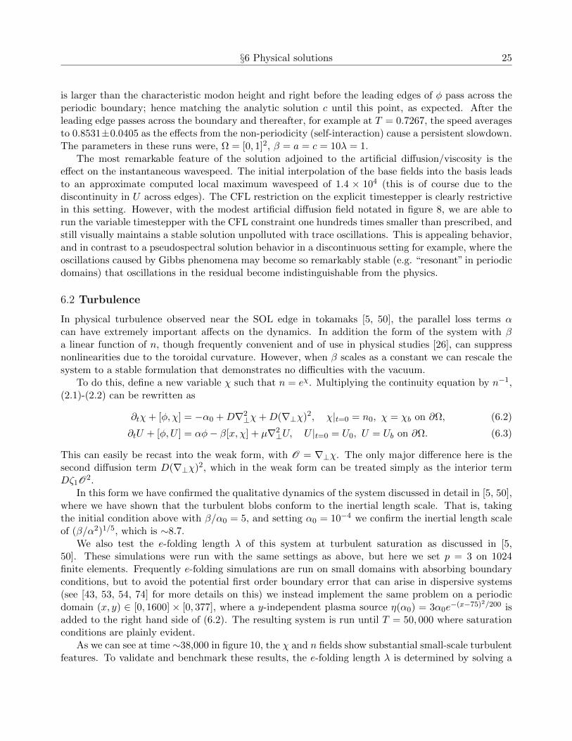
is larger than the characteristic modon height and right before the leading edges of φ pass across theperiodic boundary; hence matching the analytic solution c until this point, as expected. After theleading edge passes across the boundary and thereafter, for example at T = 0.7267, the speed averagesto 0.8531±0.0405 as the effects from the non-periodicity (self-interaction) cause a persistent slowdown.The parameters in these runs were, Ω = [0, 1]2, β = a = c = 10λ = 1.
The most remarkable feature of the solution adjoined to the artificial diffusion/viscosity is theeffect on the instantaneous wavespeed. The initial interpolation of the base fields into the basis leadsto an approximate computed local maximum wavespeed of 1.4 × 10⁴ (this is of course due to thediscontinuity in U across edges). The CFL restriction on the explicit timestepper is clearly restrictivein this setting. However, with the modest artificial diffusion field notated in figure 8, we are able torun the variable timestepper with the CFL constraint one hundreds times smaller than prescribed, andstill visually maintains a stable solution unpolluted with trace oscillations. This is appealing behavior,and in contrast to a pseudospectral solution behavior in a discontinuous setting for example, where theoscillations caused by Gibbs phenomena may become so remarkably stable (e.g. “resonant” in periodicdomains) that oscillations in the residual become indistinguishable from the physics.
6.2 Turbulence
In physical turbulence observed near the SOL edge in tokamaks [5, 50], the parallel loss terms αcan have extremely important affects on the dynamics. In addition the form of the system with βa linear function of n, though frequently convenient and of use in physical studies [26], can suppressnonlinearities due to the toroidal curvature. However, when β scales as a constant we can rescale thesystem to a stable formulation that demonstrates no difficulties with the vacuum.
To do this, define a new variable χ such that n = eχ. Multiplying the continuity equation by n−1,(2.1)-(2.2) can be rewritten as
∂tχ+ [φ, χ] = −α0 +D∇2⊥χ+D(∇⊥χ)2, χ|t=0 = n0, χ = χb on ∂Ω, (6.2)
∂tU + [φ,U ] = αφ− β[x, χ] + µ∇2⊥U, U |t=0 = U0, U = Ub on ∂Ω. (6.3)
This can easily be recast into the weak form, with O = ∇⊥χ. The only major difference here is thesecond diffusion term D(∇⊥χ)2, which in the weak form can be treated simply as the interior termDζ1O2.
In this form we have confirmed the qualitative dynamics of the system discussed in detail in [5, 50],where we have shown that the turbulent blobs conform to the inertial length scale. That is, takingthe initial condition above with β/α0 = 5, and setting α0 = 10−4 we confirm the inertial length scaleof (β/α2)1/5, which is ∼8.7.
We also test the e-folding length λ of this system at turbulent saturation as discussed in [5,50]. These simulations were run with the same settings as above, but here we set p = 3 on 1024finite elements. Frequently e-folding simulations are run on small domains with absorbing boundaryconditions, but to avoid the potential first order boundary error that can arise in dispersive systems(see [43, 53, 54, 74] for more details on this) we instead implement the same problem on a periodicdomain (x, y) ∈ [0, 1600] × [0, 377], where a y-independent plasma source η(α0) = 3α0e
−(x−75)2/200 isadded to the right hand side of (6.2). The resulting system is run until T = 50, 000 where saturationconditions are plainly evident.
As we can see at time ∼38,000 in figure 10, the χ and n fields show substantial small-scale turbulentfeatures. To validate and benchmark these results, the e-folding length λ is determined by solving a

26 DG methods for plasma physics in the scrape-off layer of tokamaks
Figure 9: The center of mass and center of mass velocity plots on the right show single blob validationagainst BOUT++ [50] and Garcia [26] et al. To the left is a turbulent saturation test at T ∼38,000,where the top graph shows the density n, the middle graph shows the density field with φ contoursoverlaid, and the bottom its associated χ field.
least squares fit of L−1y
∫y ndy = e−x/λ for λ, where Ly = 377, and the Rayleigh number Ra = 10−4.
These results are compared to an exact simulation of BOUT++ [50] to find an nearly exact e-foldinglength of λ = 43 between the two codes.

§7 Conclusion 27
0 20 40 60 80 100 120 140 160 180−5
−4
−3
−2
−1
0
1
x
log(
∫t 2 t 1
1 Ly
∫ Ωyndydt)
e-folding length, λ
ArcOn raw data
ArcOn linear regression
ArcOn top prediction bounds at 99%
ArcOn bottom prediction bounds at 99%
BOUT++ raw data
BOUT++ linear regression
BOUT++ top prediction bounds at 99%
BOUT++ bottom prediction bounds at 99%
Figure 10: Here we show the equivalent slope and the prediction bound overlap between BOUT++and ArcOn at turbulent saturation relative to the e-folding length.
§7 Conclusion
We have presented a new architecture called ArcOn for studying the dynamics of filamentary blobstransported through the scrape-off layer of tokamaks. In this regard we have implemented a fullydiscontinuous Galerkin method for solving (2.1)-(2.3). In contrast to mixed form finite element meth-ods, for example, which use continuous Galerkin projections [53] to recover solutions to Poisson, ourpresent approach preserves the discontinuous function spaces throughout the computation, thus ex-panding the well-posedness of the space of admissible solutions. Our formulation is novel, in thatis supports multiples basis functions, and is run using modal, nodal, or mixed nodal/modal finiteelements. In addition, we have developed and analyzed three classes of upwinding schemes, whichwe discern here as the strong, semistrong, and quasistrong flux formulations developed to handle theparticular cross-product driven fluxes that arise in (2.1)-(2.2). We further implement a Poisson solverusing a unified implementation that supports, SIPG, NIPG, IIPG, LDG, Brezzi, and Bassi-Rebayfluxes. Future work in this direction include adding functionality to support LDG, LDG2, HDG andBaumann-Oden formulations [9], as well as developing a strongly coupled Riemann solver for thebracketed convective fluxes.
We have carried out a program of thorough numerical verification of the code, which is seen toconverge to the prescribed order in each of its respective subsystems, providing numerically smoothinitial data. We then discussed some of the regularization aspects of DG methods that render themremarkably flexible. Along these lines we have developed a novel artificial diffusion/viscosity algorithmpredicated on a heuristic entropy measure of the relative local variation in the base variable. Thisregularity sensor Sij is shown in a number of examples to produce robust solutions.
We have validated ArcOn on a collection of physical test cases. The evolution of modon solutionsto (2.1)-(2.3), which introducd a number of numerical difficulties (singular behavior in the initial stateof the system) are easily managed with modest εi. ArcOn was then validated against blob dynamicsand benchmarked against BOUT++ [24] and Garcia [26] et al. Finally turbulent saturation behaviorwas benchmarked against BOUT++ [24]. The direction of future work in these areas include theexpansion of the physics in our model to include advanced turbulent features of the flow, such as theeffects of electron temperature gradients and magnetic chaos.

28 DG methods for plasma physics in the scrape-off layer of tokamaks
§8 Acknowledgements
The first author would like to thank Phillip Schmitz, John Evans, Jed Brown, Timo Heister, AmmarHakim, Paul Bauman, Georg Stadler, Logan Moon, Kyle Mandli, Andy Terrel, Clint Dawson, andIrene Gamba for fun, insightful, and incredibly helpful discussions. This work was supported by theU.S. Department of Energy under Contract No. DE-FG02-04ER-54742.
References
[1] C. Altmann, A. Beck, A. Birkefeld, F. Hindenlang, M. Staudenmaier, G. Gassner, and C.-D.Munz. Discontinuous Galerkin for high performance computational fluid dynamics (hpcdg). InW. E. Nagel, D. B. Kroner, and M. M. Resch, editors, High Performance Computing in Scienceand Engineering ’11, pages 277–288. Springer Berlin Heidelberg, 2012.
[2] D. Arnold, F. Brezzi, B. Cockburn, and D. Marini. Discontinuous Galerkin methods for ellipticproblems. In Discontinuous Galerkin methods (Newport, RI, 1999), volume 11 of Lect. NotesComput. Sci. Eng., pages 89–101. Springer, Berlin, 2000.
[3] D. N. Arnold. An interior penalty finite element method with discontinuous elements. SIAM J.Numer. Anal., 19(4):742–760, 1982.
[4] D. N. Arnold, F. Brezzi, B. Cockburn, and L. D. Marini. Unified analysis of discontinuous Galerkinmethods for elliptic problems. SIAM J. Numer. Anal., 39(5):1749–1779, 2001/02.
[5] A. Aydemir. Convective transport in the scrape-off layer of tokamaks. Physics of Plasmas, 12(6),Jun 2005.
[6] S. Balay, J. Brown, , K. Buschelman, V. Eijkhout, W. D. Gropp, D. Kaushik, M. G. Knepley,L. C. McInnes, B. F. Smith, and H. Zhang. PETSc users manual. Technical Report ANL-95/11- Revision 3.4, Argonne National Laboratory, 2013.
[7] W. Bangerth, T. Heister, G. Kanschat, et al. deal.II Differential Equations Analysis Library,Technical Reference. http://www.dealii.org.
[8] F. Bassi and S. Rebay. A high-order accurate discontinuous finite element method for the nu-merical solution of the compressible Navier-Stokes equations. J. Comput. Phys., 131(2):267–279,1997.
[9] C. Baumann and J. Oden. A discontinuous hp finite element method for convection-diffusionproblems. Computer Methods in Applied Mechanics and Engineering, 175(3-4):311–341, JUL 21999.
[10] J. Borggaard, T. Iliescu, and J. P. Roop. A Bounded Artificial Viscosity Large Eddy SimulationModel. SIAM Journal on Numerical Analysis, 47(1):622–645, 2009.
[11] F. Brezzi, G. Manzini, D. Marini, P. Pietra, and A. Russo. Discontinuous finite elements fordiffusion problems. in Atti Convegno in onore di F. Brioschi (Milan, 1997), Istituto Lombardo,Accademia di Scienze e Lettere, Milan, Italy, pages 197–217, 1999.

REFERENCES 29
[12] C. Burstedde, L. C. Wilcox, and O. Ghattas. p4est: Scalable algorithms for parallel adaptivemesh refinement on forests of octrees. SIAM Journal on Scientific Computing, 33(3):1103–1133,2011.
[13] Y. Cheng, I. M. Gamba, and P. J. Morrison. Study of conservation and recurrence of Runge-Kuttadiscontinuous Galerkin schemes for Vlasov-Poisson systems. Journal of Scientific Computing,56(2):319–349, AUG 2013.
[14] Y. Cheng, F. Li, J. Qiu, and L. Xu. Positivity-preserving DG and central DG methods for idealMHD equations. Journal of Computational Physics, 238:255–280, Apr 1 2013.
[15] B. Cockburn, S.-Y. Lin, and C.-W. Shu. TVB Runge-Kutta local projection discontinuousGalerkin finite element method for conservation laws. III. One-dimensional systems. J. Com-put. Phys., 84(1):90–113, 1989.
[16] B. Cockburn and C.-W. Shu. The runge-kutta discontinuous galerkin method for conservationlaws v: Multidimensional systems. Journal of Computational Physics, 141(2):199 – 224, 1998.
[17] B. Cockburn and C.-W. Shu. Runge-Kutta discontinuous Galerkin methods for convection-dominated problems. J. Sci. Comput., 16(3):173–261, 2001.
[18] C. Dawson, S. Sun, and M. F. Wheeler. Compatible algorithms for coupled flow and transport.Comput. Methods Appl. Mech. Engrg., 193(23-26):2565–2580, 2004.
[19] C. Dawson, C. J. Trahan, E. J. Kubatko, and J. J. Westerink. A parallel local timestepping Runge-Kutta discontinuous Galerkin method with applications to coastal ocean modeling. ComputerMethods in Applied Mechanics and Engineering, 259:154–165, Jun 1 2013.
[20] C. Dawson, M. Wheeler, and J. Proft. Adaptive stencil and discontinuous Galerkin methods fortransport equations on triangular grids. Technical Report, 1999.
[21] A. Dedner and M. Ohlberger. A new hp-adaptive DG scheme for conservation laws based on errorcontrol. In Hyperbolic problems: theory, numerics, applications, pages 187–198. Springer, Berlin,2008.
[22] D. A. D’Ippolito, J. R. Myra, and S. J. Zweben. Convective transport by intermittent blob-filaments: Comparison of theory and experiment. Physics of Plasmas, 18(6):060501, 2011.
[23] B. D. Dudson, M. V. Umansky, X. Q. Xu, P. B. Snyder, and H. R. Wilson. BOUT++: Aframework for parallel plasma fluid simulations. Computer Physics Communications, 180(9):1467–1480, SEP 2009.
[24] B. D. Dudson, M. V. Umansky, X. Q. Xu, P. B. Snyder, and H. R. Wilson. BOUT++: Aframework for parallel plasma fluid simulations. COMPUTER PHYSICS COMMUNICATIONS,180(9):1467–1480, SEP 2009.
[25] M. Feistauer and V. Kucera. On a robust discontinuous Galerkin technique for the solution ofcompressible flow. J. Comput. Phys., 224(1):208–221, 2007.
[26] O. E. Garcia, N. H. Bian, and W. Fundamenski. Radial interchange motions of plasma filaments.Physics of Plasmas, 13(8), AUG 2006.

30 DG methods for plasma physics in the scrape-off layer of tokamaks
[27] M. Ghil, M. Kimoto, and J. Neelin. Nonlinear dynamics and predictability in the atmosphericsciences. Reviews of Geophysics, 29(1, S):46–55, 1991.
[28] R. E. Heath, I. M. Gamba, P. J. Morrison, and C. Michler. A discontinuous Galerkin method forthe Vlasov-Poisson system. Journal of Computational Physics, 231(4):1140–1174, Feb 20 2012.
[29] J. Hesthaven, J. Lynov, and J. Nycander. Dynamics of nonstationary dipole vortices. Physics ofFluids a-Fluid Dynamics, 5(3):622–629, MAR 1993.
[30] J. S. Hesthaven and T. Warburton. Nodal discontinuous Galerkin methods, volume 54 of Texts inApplied Mathematics. Springer, New York, 2008. Algorithms, analysis, and applications.
[31] G. Jacobs and J. Hesthaven. High-order nodal discontinuous Galerkin particle-in-cell method onunstructured grids. Journal of Computational Physics, 214(1):96–121, May 1 2006.
[32] G. B. Jacobs and J. S. Hesthaven. Implicit-explicit time integration of a high-order particle-in-cellmethod with hyperbolic divergence cleaning. Computer Physics Communications, 180(10):1760–1767, OCT 2009.
[33] D. Jovanovic and P. K. Shukla. Structures and Zonal Flows in Magnetized Plasmas. In Elias-son, B and Shukla, PK, editor, New Frontiers in Advanced Plasma Physics, volume 1306 of AIPConference Proceedings, pages 150–159. Abdus Salam Int Ctr Theoret Phys, 2010. ICTP Inter-national Advanced Workshop on the Frontiers of Plasma Physics, Abdus Salam Int Ctr TheoretPhys, Trieste, Italy, Jul 05-16, 2010.
[34] A. Kloeckner, T. Warburton, J. Bridge, and J. S. Hesthaven. Nodal discontinuous Galerkinmethods on graphics processors. Journal of Computational Physics, 228(21):7863–7882, Nov2009.
[35] S. I. Krasheninnikov, D. A. D’Ippolito, and J. R. Myra. Recent theoretical progress in understand-ing coherent structures in edge and SOL turbulence. Journal of Plasma Physics, 74(5):679–717,OCT 2008.
[36] E. Kubatko, C. Dawson, and J. Westerink. Time step restrictions for Runge-Kutta discontinuousGalerkin methods on triangular grids. J. Comput. Phys., 227(23):9697–9710, 2008.
[37] E. J. Kubatko, J. J. Westerink, and C. Dawson. hp discontinuous Galerkin methods for advec-tion dominated problems in shallow water flow. Computer Methods in Applied Mechanics andEngineering, 196(1-3):437–451, 2006.
[38] E. J. Kubatko, J. J. Westerink, and C. Dawson. Semi discrete discontinuous galerkin methods andstage-exceeding-order, strong-stability-preserving runge-kutta time discretizations. J. Comput.Phys., 222(2):832–848, Mar. 2007.
[39] D. Kuzmin. A vertex-based hierarchical slope limiter for p-adaptive discontinuous Galerkin meth-ods. J. Comput. Appl. Math., 233(12):3077–3085, 2010.
[40] D. Kuzmin, M. J. Shashkov, and D. Svyatskiy. A constrained finite element method satisfying thediscrete maximum principle for anisotropic diffusion problems. Journal of Computational Physics,228(9):3448–3463, May 20 2009.

REFERENCES 31
[41] D. Kuzmin and S. Turek. High-resolution FEM-TVD schemes based on a fully multidimensionalflux limiter. Journal of Computational Physics, 198(1):131–158, Jul 20 2004.
[42] V. D. Larichev and G. M. Reznik. Two-dimensional solitary rossby waves. Dokl. Akad. NaukSSSR, 231:1077, 1976.
[43] I. Lie. Well-posed transparent boundary conditions for the shallow water equations. Appl. Numer.Math., 38(4):445–474, 2001.
[44] A. Loarte, B. Lipschultz, A. Kukushkin, G. Matthews, P. Stangeby, N. Asakura, G. Counsell,G. Federici, A. Kallenbach, K. Krieger, A. Mahdavi, V. Philipps, D. Reiter, J. Roth, J. Strachan,D. Whyte, R. Doerner, T. Eich, W. Fundamenski, A. Herrmann, M. Fenstermacher, P. Ghendrih,M. Groth, A. Kirschner, S. Konoshima, B. LaBombard, P. Lang, A. Leonard, P. Monier-Garbet,R. Neu, H. Pacher, B. Pegourie, R. Pitts, S. Takamura, J. Terry, E. Tsitrone, the ITPA Scrape-offLayer, and D. P. T. Group. Chapter 4: Power and particle control. Nuclear Fusion, 47(6):S203–S263, 2007.
[45] J. Loverich, A. Hakim, and U. Shumlak. A Discontinuous Galerkin Method for Ideal Two-FluidPlasma Equations. Communications in Computational Physics, 9(2):240–268, Feb 2011.
[46] J. Loverich and U. Shumlak. A discontinuous Galerkin method for the full two-fluid plasma model.Computer Physics Communications, 169(1-3):251–255, Jul 1 2005. Europhysics Conference onComputational Physics, Genoa, ITALY, SEP 01-04, 2004.
[47] A. Mani, J. Larsson, and P. Moin. Suitability of artificial bulk viscosity for large-eddy simulationof turbulent flows with shocks. Journal of Computational Physics, 228(19):7368–7374, OCT 202009.
[48] E. T. Meier, A. H. Glasser, V. S. Lukin, and U. Shumlak. Modeling open boundaries in dissipativeMHD simulation. Journal of Computational Physics, 231(7):2963–2976, Apr 1 2012.
[49] J. Meiss and W. Horton. Solitary vortices in the presence of magnetic shear. Phys. Plasmas,26(4):990–997, April 1983.
[50] D. Meyerson, C. Michoski, W. Horton, and F. Waelbroeck. Radial interchange driven turbulenceand transport across chaotic magnetic field lines. In preparation, 2014.
[51] C. Michoski, A. Alexanderian, C. Dawson, and E. Kubatko. Numerical stability analysis forexplicit runge-kutta methods in nonlinear discontinuous systems. preprint, 2014.
[52] C. Michoski, J. Evans, and P. Schmitz. Discontinuous Galerkin hp-adaptive Methods for Multi-scale Chemical Reactors I: Quiescent Reactors. preprint, 2014.
[53] C. Michoski, J. A. Evans, P. G. Schmitz, and A. Vasseur. Quantum hydrodynamics with trajec-tories: the nonlinear conservation form mixed/discontinuous Galerkin method with applicationsin chemistry. J. Comput. Phys., 228(23):8589–8608, 2009.
[54] C. Michoski, J. A. Evans, P. G. Schmitz, and A. Vasseur. A discontinuous Galerkin method forviscous compressible multifluids. J. Comput. Phys., 229(6):2249–2266, 2010.

32 DG methods for plasma physics in the scrape-off layer of tokamaks
[55] C. Michoski, C. Mirabito, C. Dawson, E. Kubatko, D. Wirasaet, and J. Westerlink. Adaptivehierarchic transformations over dynamic p-enriched schemes applied to generalized DG systems.J. Comput. Phys., submitted, 2010.
[56] P. Morrison. A paradigm for joined hamiltonian and dissipative systems. Physica D, 18(1-3):410–419, Jan 1986.
[57] E. Neven. Linear stability of modons on a sphere. Journal of the Atmospheric Sciences,58(16):2280–2305, 2001.
[58] J. T. Oden, I. Babuska, and C. E. Baumann. A discontinuous hp finite element method fordiffusion problems. J. Comput. Phys., 146(2):491–519, 1998.
[59] J. L. Peterson and G. W. Hammett. Positivity preservation and advection algorithms with ap-plications to edge plasma turbulence. SIAM Journal on Scientific Computing, 35(3):B576–B605,2013.
[60] B. Riviere. Discontinuous Galerkin methods for solving elliptic and parabolic equations, volume 35of Frontiers in Applied Mathematics. Society for Industrial and Applied Mathematics (SIAM),Philadelphia, PA, 2008. Theory and implementation.
[61] J. A. Rossmanith and D. C. Seal. A positivity-preserving high-order semi-Lagrangian discon-tinuous Galerkin scheme for the Vlasov-Poisson equations. Journal of Computational Physics,230(16):6203–6232, Jul 10 2011.
[62] D. A. Russell, J. R. Myra, and D. A. D’Ippolito. Saturation mechanisms for edge turbulence.Physics of Plasmas, 16(12):122304, 2009.
[63] S. Ruuth. Global optimization of explicit strong-stability-preserving Runge-Kutta methods. Math.Comp., 75(253):183–207 (electronic), 2006.
[64] S. K. Saha and S. Chowdhury. Intermittent transport in the scrape-off layer of the SINP tokamak.Physics of Plasmas, 13(9), SEP 2006.
[65] H. Sakuma and M. Ghil. Stability of propagating modons for small-amplitude perturbations.Physics of Fluids a-Fluid Dynamics, 3(3):408–414, MAR 1991.
[66] C.-W. Shu and S. Osher. Efficient implementation of essentially nonoscillatory shock-capturingschemes. J. Comput. Phys., 77(2):439–471, 1988.
[67] U. Shumlak, R. Lilly, N. Reddell, E. Sousa, and B. Srinivasan. Advanced physics calculationsusing a multi-fluid plasma model. Computer Physics Communications, 182(9, SI):1767–1770, SEP2011.
[68] B. Srinivasan, A. Hakim, and U. Shumlak. Numerical Methods for Two-Fluid Dispersive FastMHD Phenomena. Communications in Computational Physics, 10(1):183–215, Jul 2011.
[69] T. Toulorge and W. Desmet. CFL conditions for runge–kutta discontinuous galerkin methodson triangular grids. Journal of Computational Physics, 230(12):4657 – 4678, 2011.
REFERENCES 33
[70] F. Waelbroeck, P. Morrison, and W. Horton. Hamiltonian formulation and coherent structuresin electrostatic turbulence. Plasma Physics and Controlled Fusion, 46(9):1331, 2004.
[71] Z. J. Wang, K. Fidkowski, R. Abgrall, F. Bassi, D. Caraeni, A. Cary, H. Deconinck, R. Hartmann,K. Hillewaert, H. T. Huynh, N. Kroll, G. May, P.-O. Persson, B. van Leer, and M. Visbal. High-order CFD methods: current status and perspective. International Journal for Numerical Methodsin Fluids, 72(8):811–845, Jul 20 2013.
[72] T. Warburton and G. Karniadakis. A discontinuous Galerkin method for the viscous MHDequations. Journal of Computational Physics, 152(2):608–641, Jul 1 1999.
[73] L. Wilcox, G. Stadler, C. Burstedde, and O. Ghattas. A high-order discontinuous Galerkin methodfor wave propagation through coupled elastic-acoustic media. Journal of Computational Physics,229(24):9373–9396, DEC 10 2010.
[74] D. Wirasaet, S. Brus, C. Michoski, E. Kubatko, J. Westerink, and C. Dawson. Artificial boundarylayers in the discontinuous Galerkin shallow water solution in channels. preprint, 2013.
[75] D. Wirasaet, S. Tanaka, E. J. Kubatko, J. J. Westerink, and C. Dawson. A performance com-parison of nodal discontinuous Galerkin methods on triangles and quadrilaterals. InternationalJournal for Numerical Methods in Fluids, 64(10-12):1336–1362, Dec 30 2010. 15th InternationalConference on Finite Elements in Flow Problems, Tokyo, Japan, Apr 01-03, 2009.
[76] V. Zingan, J.-L. Guermond, J. Morel, and B. Popov. Implementation of the entropy viscositymethod with the discontinuous Galerkin method. Computer Methods in Applied Mechanics andEngineering, 253:479–490, JAN 1 2013.
![A discontinuous Galerkin method for two-temperature plasmas€¦ · to develop effective high-order methods for plasma flows have been reported in [19–21]. Discontinuous Galerkin](https://img.dokumen.tips/doc/110x75/60620c3d0c6374232b4a1d95/a-discontinuous-galerkin-method-for-two-temperature-plasmas-to-develop-eiective.jpg)


![Discontinuous Galerkin Methods - [Groupe Calcul]](https://img.dokumen.tips/doc/110x75/61fb86042e268c58cd5f2ee4/discontinuous-galerkin-methods-groupe-calcul.jpg)