Embed Size (px)
Citation preview

Diffraction of sound around corners and over wide barriers*
Allan D. Pierce t
Acoustics and Vibrations Laboratory, Massachusetts Institute of Technology, Cambridge, Massachusetts 02139
(Received 19 December 1972; revised 9 July 1973)
Formulas and procedures are described for the estimation of sound pressure ß amplitudes at locations partially shielded from the source by a barrier. The analytical development is based on the idealized models of a wave from a point or extended source incident on a rigid wedge or a three-sided semi-infinite barrier. Versions of the uniform asymptotic solution for the wedge problem which are convenient for numerical predictions are derived in terms of auxiliary Fresnel functions by means of complex variable techniques previously employed by Pauli from a generalization of the exact integral solution developed by Sommerfeld, MacDonald, Bromwich, and others and are interpreted within the spirit of Keller's geometrical theory of diffraction. The Kirchhoff approximation in terms of the Fresnel number is obtained in the limit of small angular deflections from shadow zone boundaries. An approximate and relatively simple expression for the double-edge diffraction by a thick three-sided barrier is given based on the single wedge diffraction solution and on concepts inherent to the geometrical theory of diffraction which reduces to finite and realistic limits when either source or
listener are near the extended plane of the barrier's top. A simple approximation suggested by Maekawa based on the replacement of actual barriers by an equivalent thin screen with diffraction treated by the Kirchhoff approximation is discussed in terms of the present theory and it is concluded that in some instances this approximation may lead to sizeable errors. An alternate scheme is suggested whereby one approximates the actual barrier by a three-sided barrier wholly contained within the actual barrier.
Subject Classification: 28.40; 20.30.
INTRODUCTION
The possibility of using barriers as a means of re- ducing noise near highways 1 and airport runways has revived interest in the classical problem of predicting the diffraction of sound around a barrier. Within the
broader context of wave diffraction in general, an exten- sive literature, much of which is far from new, per- tains to this problem. In actual practice, however, the techniques most commonly employed are based on the idealized problem of diffraction by a thin rigid screen. A standard and often used solution for this particular case is that due in essence to Kirchhoff which leads to
the result •'a that diffracted amplitudes at large distances from the barrier may, apart from multiplicative factors embodying geometrical spreading of the incident wave, be expressed in terms of a single dimensionless param- eter, the Fresnel number. Computations are according- ly reduced to that of evaluating the Fresnel number and then referring to readily available plots of barrier at- tenuation 4-6 versus Fresnel number. Alternately, one may make computations based on Sommerfeld's exact solution v for the problem. Kurze and Anderson, 6 for example, h•fve discussed the use of Keller' s expression 8'9 for the asymptotic form of the counterpart of Sommer- feld's solution when the incident wave is generated by a point source. Since, in its quoted form, this solution diverges at the boundary of the shadow zone, Kurze and Anderson suggest a transition formula to remove this singularity. Alternate expressions accomplishing the
same purpose in terms of Fresnel integrals and related transcendental functions can be deduced from the more
recent work on uniform approximations by Ahluwalia, Lewis, and Boersma lø for the case of a plane screen and by Ahluwalia u for the case of a wedge of arbitrary angle. Both of these latter theories are based on Lud- wig's general method • for obtaining uniform approxi- mations. More restricted forms of uniform asymptotic solutions were obtained somewhat earlier by Whipple, zs by Pauli, •4 and by Oberhettinger. •s
Although Maekawa • has suggested an ingenious tech- nique for replacing barriers of more general shape by an equivalent thin screen, there appears to be relatively little theoretical basis to this technique except in the case of small angle diffraction by wedges. Thus there would appear to be some need for a theory applicable to barriers not readily idealized as plane screens. It is to this purpose that the present paper is devoted. Spe- cifically, it discusses the diffraction of waves by a wedge of arbitrary angle and by three-sided infinite barriers, the sides of which are planar, and suggests that the results of the analysis of these two general classes of problems may be used to estimate diffraction around barriers of more general shapes.
Although diffraction by wedges has been extensively treated 17-•'4 in the literature, the nature of the solutions given is not necessarily the most convenient for compu- tations of diffracted amplitudes in cases of practical
941 J. Acoust. Soc. Am., Vol. 55, No. 5, May 1974 Copyright ¸ 1974 by the Acoustical Society of America 941
Downloaded 26 Aug 2013 to 129.173.72.87. Redistribution subject to ASA license or copyright; see http://asadl.org/terms
942 A.D. Pierce: Diffraction around corners and over barriers 942
interest. In the present paper, suitable uniform asymp- totic expressions are exhibited for waves generated by a point source in the vicinity of a barrier applicable at points both near and far from shadow zone boundaries. These expressions and their generalization to the case of waves from a spatial distribution of sources are given in Sec. I. Although similar expressions accom- plishing the same purpose can be deduced from the more general results of Ahluwalia, u an independent but ab- breviated derivation is given here for completeness. The emphasis is primarily on giving the results in a form which facilitates numerical predictions.
While the wedge problem is of significance in the dif- fraction of sound around corners, such as around the corner of a building, our primary purpose of treating it here is that it be available as a building block for the development of a theory (double-edge diffraction) for the diffraction of sound around a three-sided barrier.
Earlier work on this problem such as, for example, that by Jones •'5 on the diffraction of waves by thick semi- infinite plates, appears to be difficult to use in numerical computations unless one restricts his attention tobarrier thicknesses less than or comparable to a wavelength. Maekawa, Fujiwara, Nagano, and Morimoto •'6 have re- cently introduced one approximate scheme based onknown results for diffraction of waves by thin screens, but un- fortunately this scheme has very little theoretical basis. The method proposed in the present paper is guided by concepts inherent in Keller's 8'9'•'7 geometrical theory of diffraction. Although Keller's theory has been used by Hutchins and Kouyoumijan •'8 in the prediction of the far- field radiation pattern of a baffled array and has been widely cited in more recent work on the uniform theory of diffraction, it would appear that its application to acous- tical problems has not yet become widespread. The
,
existence of the Keller theory and of the literature per- taining to its application makes it a relatively straight- forward task for one to derive an asymptotic expression
SOURCE
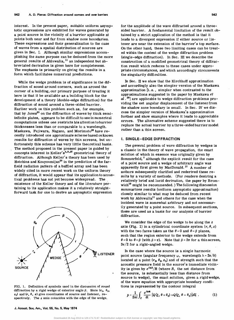
FIG. 1. Definition of symbols used in the discussion of sound diffraction by a rigid wedge of exterior angle fl. Here (r0, 00, z0) and 0% 0, z) give coordinates of source and listener, re- spectively. The z axis coincides with the edge of the wedge.
for the amplitude of the wave diffracted around a three- sided barrier. A fundamental limitation of the result ob-
tained by a strict application of the method is that it leads to a divergent expression if either source or lis- tener are near the extension of the barrier's top surface. On the other hand, these two limiting cases can be treat- ed within the context of the wedge diffraction problem (single-edge diffraction). In Sec. III we describe the construction of a modified geometrical theory of diffrac- tion result which reduces to these cases under appro- priate circumstances, and which accordingly circumvents the singularity difficulties.
In Sec. II we show that the Kirchhoff approximation and accordingly also the simpler version of the Maekawa approximation [i.e., simpler when contrasted to the approximations suggested in the paper by Maekawa et al. •'6] are applicable to wedge diffraction problems pro- viding the net angular displacement of the listener from the shadow zone boundary is small. In Sec. IV we dis- cuss the simpler version of Maekawa's approximation further and show examples where it leads to appreciable errors. The alternative scheme suggested there is to replace the actual barrier by a three-sidedbarrier model rather than a thin screen.
I. SINGLE-EDGE DIFFRACTION
The general problem of wave diffraction by wedges is a classic in the theory of wave propagation, the exact solution of'which in essence was originally given by Sommerfeld, ? although the explicit result for the case of a point source and a wedge of arbitrary angle was apparently first given by MacDonald. •? A number of authors subsequently clarified and rederived these re- sults by a variety of methods. (For readers desiring a relatively brief and lucid derivation, the paper by Brom- wich •9 might be recommended. ) The following discussion summarizes results (uniform asymptotic approximation) closely similar to what may be deduced from recent work by Ahluwalia • and others for the case when the incident wave is somewhat arbitrary and not necessar- ily generated by a point source. In subsequent sections, these are used as a basis for our analysis of barrier diffraction.
We consider the edge of the wedge to be along the z axis (Fig. 1) in a cylindrical coordinate system (r, O,z) with the two faces taken as the 0 = 0 and 0 = • planes, such that the region exterior to the wedge extends from 0 = 0 to 0 = • (with • > •). Note that • = 2• for a thin screen, 3•/2 for a right-angled wedge.
In the case where the source is a single harmonic point source (angular frequency •0, wavelength X = 2•'/k) located at a point (r0, 00, z0) and of strength such that the acoustic pressure field in the source's immediate vicin- ity is given by e•kR/R (where R, the net distance from the source, is substantially less than distance from source to wedge), the exact solution, given a rigid wedge, of the wave equation with appropriate boundary condi- tions is represented by the contour integral
1 /c P: 2-• • [Q(•' 0 + 0o) +Q(•, 0 - Oo)]d•; . (1)
J. Acoust. Soc. Am., Vol. 55, No. 5, May 1974
Downloaded 26 Aug 2013 to 129.173.72.87. Redistribution subject to ASA license or copyright; see http://asadl.org/terms

943 A.D. Pierce: Diffraction around corners and over barriers 943
B RANCH
POLES
= I •r 2•r •R
(a) (b)
•R
FIG. 2. Integration paths in the complex • plane for the evaluation of the contour integral solution of the wedge diffraction problem. (a) Form of path similar to that specified in paper by Bromwich. (b) Deformed contour. Paths C 1 and C•. are paths of steepest descent, while C 3 encircles all poles on the real axis between 0 and v.
Here the complex function (R is given by
= [r + r0 + - - 2rr0 cos] (2) and is defined such that it is real and positive all along the real axis. Branch cuts extend vertically upwards or downwards from branch points at 2n• +is or 2n•r- is, respectively, where n is any integer and where • is a real positive quantity defined such that (R =0 at a branch point.
The other function Q (•, 8) in the integrand is given for arbitrary argume. nt pair (•, 8) by
Q(•, 8) = - v sin(v•)/[cos(v•) - cos(vS)] , (3)
where •= •/•. The contour C is as sketched in Fig. 2(a). In Eq. 1, we adhere to the usual convention of suppress- ing the time variation factor e '•'• in discussions of steady waves. (While the above solution has not been explicitly taken per se from the existing literature, it is easily obtained from Bromwich's expressions with a slight change in nomenclature. )
The generalization of the above to the case when the
source is not a single point source, but a spatial dis- tribution of point sources, each of frequency • and each lying on the plane 8 = 80, is also given by Eq. 1, only with e•/(R replaced by p•(z, 80 +•, z), where for real 8, p•(r, 8, z) is the acoustic pressure (incident wave) as heard at point (r, 8, z) in the absence of the wedge. For complex •, p•(z, 80 + •, •) can in principle be obtained from analytic continuation of its values along the real axis and from the requirement that it be analytic every- where in the • plane with the possible exception of the branch lines where Re(i ) is an integer multiple of 2•. One may note that this generalization includes as spe- cial cases that (i)when the source is a line source, and (ii) when the incident wave is a plane wave with direc- tion of propagation parallel to the 8= 80 plane.
Of principal interest here is the field when sources
and listener are all at distances large compared to a wavelength from the diffracting edge. Asymptotic ex- pressions for the integral in Eq. I (i.e., the single point source expression) may be obtained after first deform- ing the contour C to one comprised of segments, each of which is a path of steepest descent passing through a saddle point of exp(ik(R), with due account taken via the residue theorem of any poles passed over during the con- tour deformation. Such a deformed contour might be taken [Fig. 2(b)] as the path combination C• +C•.+Cs, where C• and C•. are the paths of steepest descent pass- ing through the saddle points at • = 0 and •, respectively, while C s encircles all poles (if any) lying on the real axis between 0 and • in the counterclockwise sense. One
may verify that the residue contribution from any given pole corresponds either to the incident wave or a spec- ularly reflected wave. Thus, in the sense that any wave phenomena not explicable in terms of geometrical acous- tics must be diffraction, the contribution from the steep- est descent paths must give the diffracted wave.
In the event the incident wave is not generated by a single point source, the choice of contour deformation still remains similar to that of Fig. 2(b). To facilitate the analysis, we assume that in all regions of interest, the incident wave p• may be represented by the geomet- ricai acoustics form Ae •'"" where the amplitude A and the "eikonal" •' are considered slowly varying functions of position over distances comparable to a wavelength. Here •'(r, 8, z) may be interpreted as the relative time at which a given wavefront (i.e., surface of constant phase) arrives at the point (r, 8, z). The two quantities A and •' are considered to approximately satisfy the equations (V•')•'= c '•' and V' (A•'v•')= 0 which may be de- rived •'• from the requirement that Ae •'"" satisfy the wave equation in the geometrical acoustics approximation.
J. Acoust. Soc. Am., Vol. 55, No. 5, May 1974
Downloaded 26 Aug 2013 to 129.173.72.87. Redistribution subject to ASA license or copyright; see http://asadl.org/terms

944 A.D. Pierce: Diffraction around corners and over barriers 944
J
J PDIR •:•o• + PD, FFR /
I
,I
/.•o PDIR + PREFL,,• / •
+ PDIFFR
SOURe
(a)
PDI FF R
•.I / SOURCE
/i \
PDIR 'j' PDIFFR
? .i. PDIFF R (b)
FIG. 3. Sketches of regions in which various types of waves may be heard for two general categories of source locations. The dashed
lines indicate boundaries between
the various regions. Here PDZR iS the direct wave from the source,
PDzrrR is the diffracted wave, Ps•.rL,• are waves reflected from. the wedge faces at 0 = 0 and 0 =fi, respectively.
The interpretation of contours C• and C•. in Fig. 2(b) within the context of the generalization of Eq. 1 to the case of an arbitrary incident wave is that they should be steepest descent paths of exp[i•o•'(y, •0 +•, z)] which pass through the saddlepoints at • = 0 and •. respectively. That these are actual saddlepoints follows since the assumption that sources be confined to the plane 8 = 8 0 guarantees that T be symmetric with respect to this plane
and thus that its 8 derivatives at 8 0 and 8 0 + •r vanish.
If one labels the C 1 and C s contributions as ibDlffr cor- responding to a diffracted wave and evaluates the C s con- tribution explicitly by the residue theorem, he readily finds the general result
(4)
where ibD•r is the incident or direct wave, J•Refl,• is a wave reflected from the 8= • face, and ibs.f•,0 is a wave reflected from the 8=0 face. Any of the first three terms will be zero ff the corresponding ray paths cannot be constructed according to elementary notions of geo- metrical acoustics. As regards their explicit express- ions, one may write each of these terms in the generic form j)•(y, 8wa,. ,z)Uwa,. where the subscript "Wave" is a dummy "stand-in" for one of the three subscripts"Dir," "Refl, f]," or "Refl, 0." The appropriate angular coor- dinates, 8wa,. , are given by 8, 8- 2(•- 80), and respectively. The various functions Uwa,. are defined to be unity or zero depending on whether or not the lis- tener may "see" the plane 8= 80 or its image planes formed by reflection through the wedge faces at • and 0 for the "Dir," "Refl,/•," and "Refl, 0" waves, respec- tively. Thus •fDir-- 1 if 18- 80l< •T and UDlr=0, otherwise. Analogous relations for U•.i• and U•.f•, 0 can readily be derived. In Fig. 3, we depict, for two general catego- ries of source locations, the various regimes in which one may expect to receive the various categories of waves.
Suitable expressions for the uniform asymptotic limit of the diffracted wave PDl•r are readily derived with a slight extension of the technique previously used by Pauli 14 which in turn represents an extension of the well- known saddlepoint approximation. s0 Since Q(•, 8 + 80) is odd in • and since the steepest descents path through • =0 is even about • =0 one finds the contribution from
C• to vanish identically. As regards the C s integration, the simplest version of the saddlepoint approximation would be to set Q(•, 8 + 80) in the integrand equal to Q(•r, 8+ 80) , but this unfortunately leads to singular ex- pressions near the boundaries or 2•- 7r- 80) separating the regions (Fig. 3) where (i) there are both direct and reflected waves, (ii) only direct waves, or (iii) no direct or reflected waves. Pauli's technique of circumventing this difficulty was originally applied to the case when the incident wave is planar but is also applicable to the general case considered here. We here consider two moOifications of the basic tech- nique. The simplest gives an expression which is gener- ally applicable at large distances with the possible ex- ception of the case when the wedge angle • is very close to 7r (i.e., wedges deviating only slightly from a flat surface). The second expression is somewhat more cumbersome but avoids this difficulty. In most cases of interest, the two give comparable numerical predictions.
To obtain the first such expression, the contour inte- gration C•. is approximated as follows: (i) the denomi- nator of Eq. 3 fo• Q(•, •) is expanded in a power series in •- 7r and terms of second or higher order are dis- carded. The numerator is approximated by simply re- placing • by •r. (ii) The amplitude factor (R '• or A(r, 8 o +•,z), which would appear in the integrand of Eq. I is approximated by letting 80 +• in the argument be set equal to 80+ •r. (iii) The exponent, ik6{ or iwT(r, 8 o +•,Z), is expanded in a power series in $- 7r with third or high- er terms neglected. Since • = 7r is a saddlepoint, the
J. Acoust. Soc. Am., Vol. 55, No. 5, May 1974
Downloaded 26 Aug 2013 to 129.173.72.87. Redistribution subject to ASA license or copyright; see http://asadl.org/terms

945 A.D. Pierce: Diffraction around corners and over barriers 945
first-order term vanishes identically and one in effect keeps only the zeroth and second-order terms. (iv) The original path of steepest descent is deformed to that corresponding to the truncated e i•' and the limits of in- tegration are formally considered as being at infinity.
The second such expression is derived similarly, ex- cept that step (i) above is modified such that terms up to and including seco.nd order in •- rr are included in both numerator and denominator of the expression for Q(•, 0). Then, since the remainder of the integrand (as well as the contour) is even in •- •r, one can, with no further approximation, replace Q by its symmetric part, i.e., just one-half of the sum of values of Q at equal and opposite values of •- •r. Once this is done and the resulting symmetric expression is algebraically sim- plified to a single ratio of polynomials, the numerator and denominator are further approximated by the discard of terms of greater than second order in •- •r. The re- suiting integral may then, after some algebra, be ex- pressed in terms of tabulated functions. The first der- ivation sketched above leads to the result (in terms of symbols defined further below)
p=,,,=(r, O,z )= [ei•Z/œ][e i'/ •/•f2][AoX ,) + AoX.) ] (5a)
while the second derivation gives
pr,,•,. = [e't'Z/L ][ei'/4/j"2-] {S, + S_} , (5b) with
S.= [(1 + a.)•rW. AD(W.)-- a+]/•rX+ (5c) and with an analogous expression for S..HereL = [(r + r0) a + (z- z0)Z] x/z for the point source case. For the gener- alized case, etkZ/L is replaced by Px(r, 00 + % z). In the above, X.=X(0+00) , X.=X(O-0o) ,W+=W(0+00) , etc., where the various functionsX(O), W(0), and A(0) are defined
x(e)=rM.e) , (6a)
W(0)= FN.,(0) , (6b)
cosv•r cosv•r- cosvO
A(0) - 2 1 -- cosv•r cosy O ' where (again with v = •r/B)
cosv7r- cosvO
My(O)- v sinv• '
cosvTr-- cosy 0
Nv(O)=v[1 - cosv•r cosvO] f/•' '
(6c)
(7a)
F= [2ror/(•tL)] •/•' (point source) , (8a)
F = [- (w/,r) r" (r, 0 o + •r,z)]t/•' (generalized source) . (8b)
In Eq. 8b, vt, is abbreviated notation for the function d•'v(•, •, z)/d• •. It is understood here that vt•(•', •0+•r,z) should be negative, corresponding to the assertion that, given the sources are located in the 0 = •0 plane, the incident wavefronts for given (•', z) arrive earlier at 00 +x than they do at adjacent values of 0. (An equivalent and somewhat conceptually simpler expression for r is developed in the latter part of this section. See Eq. 12.)
The function An(X ) [or An(W)] which appears in Eqs. 5 may be defined as the integral
V•-f o• ½ - u •'d u AD(X)= • -•, [Or/2)t/aX - = sign(X) [f( Ix I) - ig(
(9a)
which may in turn be expressed in terms of Fresnel integrals. The auxiliary Fresnel functionsf(X) andg(X) (here termed the diffraction functions)are equivalently defined by Eqs. 7.1.4, 7.3.5, 6, 23, 24 and are tabu- lated on pages 323-324 of the NBS Handbook of Mathe- matical Functions. at The latter expression above incor- porates the facts that AnX) is odd in X and discontinu- ous at X = 0. Note also that it requires only a definition off(X) and g(X) for positive arguments. On the basis of relations given in the NBS compilation, we can con- clude that, for small X,
f(X) = (1/2) - (rr/4)X z + (rr/3)X 3 -... , (10a)
g(x) = -x + , (0b)
while, for large X,
f(X) = 1/(rrX)- 3/(trax •) +... ,
g(x) = :) - 5/(rr4xh +...
(11a)
(11b)
The leading terms in these asymptotic series would appear to suffice for IX] > 2. This is verified in Fig. 4 where we plot f(X), g(X), along with their corresponding asymptotic forms for X < - 2. [If one neglects g(X) and uses only the leading term in Eq. 11a, the unmodified saddlepoint approximation result is obtained from either of Eqs. 5aandSb.]
The author knows of no other instance where the two
functions fiX) and g(X) have been used in the acoustical literature, so it may be of some interest to summarize here their relationship to the better known Fresnel in- tegrals
C (X) = foXcos([1/ 2]•rt•)dt , $(X) = f0Xsin([1/2]xt•)dt.
In terms of these quantities, one has
f(X): [( 1/2 ) - S] cos ([ 1/2] rrX •') - [(1/2) - C] s in([ 1/2 ]rrX •) , g(X) = [(1/2)- C] cos([1/2]rrX •') +[(1/2) -S] sin([1/2]rrX •') .
In the present paper, the quantities f(X) and g(X) are used because {i) they simplify the writing of the equations; (ii) given the fact that tabulated values and asymptotic limits are available, their use is more convenient for numerical computations; and (iii) because of the fact that, unlike the Fresnel integrals, these functions are monotonic, certain general trends (such as the mono- tonic decrease in amplitude in the shadow zone with increasing angular separation from the shadow zone boundary) are more readily apparent.
Although the diffracted wave is discontinuous wherever X(9+ 90) or X(0-00) changes sign [or, equivalently, wherever W(O +00) or W(O- 00) changes sign since W and X always have the same sign], the sum (see Eq. 4) of direct, reflected, and diffracted waves remains continu- ous. Note that the boundaries demarking regions where X+ or X. are of fixed sign coincide with the boundaries
J. Acoust. Soc. Am., Vol. 55, No. 5, May 1974
Downloaded 26 Aug 2013 to 129.173.72.87. Redistribution subject to ASA license or copyright; see http://asadl.org/terms

946 A.D. Pierce: Diffraction around corners and over barriers 946
.6
.5
z
0.4 0.8 1.2 .6 2.O
DIMENSIONLESS PARAMETER x
FIG. 4. Plots of diffraction functionsf(X) and g(X) versus X for X-<2. Also plotted (dashed lines) are the leading terms in their asymptotic expansions.
separating reception and nonreception of PDlr, PRen,•, or PRen,0' (See Fig. 3.) If X(0- •0) is negative there is a direct wave, while if it is positive there is no direct wave. Similarly, if • +•0<•r thenX(e+00)<0 and there is a PRell,0 term but no PRell,8 term; while if •r < • +e 0 < 2•-•r, then X(0 +e0)< 0 and there are no reflected wave terms; and if 8 + e0 > 2/• - v, one has X(e + e0) > 0 again and there is a PRen,• term, but no PRen,0 term. In general, one may note that whenever X(8 + 80) or X(8-e0), considered as functions of •, changes sign from negative to positive, a term vanishes in the sum of Eq. 4. The net increase ApDl•r in PD•f• when this occurs is just p•(r, •o + •, z) and this equals the value of the term deleted from the sum, as may be readfly veri- fied. Consequently, as previously asserted. the total sum remains a continuous function of e.
One may readily verify that both Eqs. 5a and 5b re- duce to zero for the case when e0 = •, /•= 2• correspond- ing to waves incident from a source on the extended plane of a thin rigid screen, thus Eq. 4 is exact in this instance. The limitations of Eq. 5a are apparent when one sets e = 0, e0 = • and lets /•-• (i.e., the limiting case of a flat surface). In this case, Eq. 5a predicts a nonzero diffracted wave, while 5b predicts PD•= = 0 (as should actually be the case).
The two different expressions, Eqs. 5a and 5b, given above for the diffracted wave can readilybedemonstrated to agree in the limit r >> 1 and r >> 2• Icot(•v) I. If the latter inequality is not satisfied (i.e., • close to •), Eq. 5b is to be preferred. Otherwise, from the stand- point of simplicity, Eq. 5a is to be preferred. The equivalence in the limit just mentioned is demonstrated in the following manner. First, one may note that if, say, both I W+ land IX+I are greater than 2, bothAr(X+ ) and S, are very nearly equal to 1/(•X0. (See Eqs. 11 and Fig. 4) Thus the only discrepancy between the two expressions, 5a and 5b, would occur when one of the quantities IX+l, IX.I, IW, I, or IW.I is less than 2. Since F >> 1 is presumed to be the case, this would imply that ½ = cos•r - cos•(8 + •0) is such that l½ I << 1, which would in turn imply that e is near one of the boundary surfaces (e = e0- •, 2/] - v - e0, etc. ) sketched in Fig. 3.
If one starts from the premise that, say, one of the quantities, IX+I or IW+ ], is less than 2, this, plus the assumed limit F >> 2• ] cot(•r) ], allows one (after consid- erable manipulation of inequalities) to show that ]½+] < (6•/F)] sin•r]. These inequalities in turn all imply that ]X+/W+ ]differs from unity by a negligible amount, that l a+ I << 1 and that l a+/X+ I << IAr(W+) I. Thus S+ re- duces to At(X,). The equivalence of the two expressions 5a and 5b for all possible cases, providing r>> 1, r >> 2•l cotter l, follows accordingly.
In regards to the diffracted wave PDlffr, it may be of assistance in computations or interpretation to derive an alternate expression for the r"(r, •0 + •, z) which appears in Eq. 8b. Since the incident wave's eikonal r(r, 8, z) is presumed to satisfy the eikonal equation, (Vr) 2= 1/c 2, one may always pick a local Cartesian coor- dinate system (x•, x•., x•) such that the x• axis is every- where normal to surfaces of constant r (wavefronts) and thus such that the xx axis is a ray. Two quantities +xx and Bs +x• may be interpreted as the principal radii of curvature of a wavefront surface near a point (xx, 0, 0), ff B•. and Bs are the corresponding radii of curvature at X•=0.
Let us note that any point (r• 8 0 + •r, z •) for given r • and z • must lie on a ray (wavefront normal). of the incident wave which just grazes the diffracting edge. We choose the x• axis to coincide with this ray, x• being zero at {he edge. The x•. axis is chosen to be perpendicular to the plane formed by the ray and the edge, while the x a axis is selected such that the three axes are orthogonal and oriented in the right-handed sense. Since the sources of the incident wave are presumed to be on the • = •o plane, symmetry requires that these x•. and x a directions be principal tangent directions of the incident wavefront all along the x• axis. Let z• be the point on the edge which intersects the incident ray and let y be the angie between the positive x axis and the outgoing incident ray (Fig. 5). The parameters B•. and B a may then be identi- fied as the two principal radii of curvature of the wave- front at the point x• on the edge. With the above choice of (x•,x•.,xa) coordinate system, one may easily derive expressions for x•,x•. or x a in terms of r, •, and •- x•.
J. Acoust. Soc. Am., Vol. 55, No. 5, May 1974
Downloaded 26 Aug 2013 to 129.173.72.87. Redistribution subject to ASA license or copyright; see http://asadl.org/terms

947 A.D. Pierce: Diffraction around corners and over barriers 947
RADIUS
Bz
RADIUS
(b)
FIG. 5. Description of incident wave near a point zE on a diffracting edge. (a) The xl axis is a ray path which intersects the edge (z axis) with angle T, while the x 2 axis is perpendicular to the plane formed by xl axis and edge. B2 and B 3 are principal radii of curvature of the incident wavefront at the edge (xl = 0, z = zE). (b) Simplified sketch for the case when T=90 ø and the incident wave is excited by a point source. Note that, in this case, B• is distance of source from edge, B•+xl is wavefront radius of curvature.
One next derives an expression valid to second order in x•. and x s for w(x•, x•., xs) from the eikonal equation given the above specifications concerning rays and radii of curvature. After expressing this in terms of r, 8, and z-zE, differentiating twice with respect to 8, followed by a setting of both x•. and x s equal to zero, one finds after some algebra a relatively simple expression for w t', such that Eq. 8b becomes
r = sin?/x(s.
Here it should be uoted that x• = r/siny is distance along the incident ray from the point z• on the edge to the point (r, 80+?r, z ) and B•. is the incident wavefront's ra- dius of curvature when viewed at the edge in a plane con- taining the ray, this plane being perpendicular to the plane formed by edge and incident ray. (See Fig. 5. ) In the event the incident wavefront is generated by a single point source at (r 0, 80, z0) one has B•. sin), = r 0 and B•+x• = L such that F reduces to the value given by Eq. 8a.
Since it is assum• that the incident wave propagates according to the geometric• acoustic equations, one may t•e the factor p•(r, •o+•, z) which replaces in Eq. 5 for the general•ed source case to be given by
p•(r, eo+•,z)= (Ba+xO(B3+x• e •(O,z s) , (13) where p•(O,z•) is the incident acoustic pressure at the point z• on the dfffracting edge. Here, the product (B•+x•)(Bs +x•) may be considered to be proportional to ray tube •ea.
In the nomin• asymptotic limit [where f(X)• 1/(•X), g(X)• 0], which should hold to a go• approximation ever•here in the farfield except near the reception-no- reception boundaries sketched in Fig. 3, Eqs. 12 and 13 •1ow one to put the diffracted wave contribution of either of Eqs. 5 in the form
I B.3 •1 pDtf•r(•', O, Z) = 2w(Bs +xx)kr sin
fM 1 1 t p,(O, zE) . x •(• + 80) + Mv(8 - O o
Here x• may be interpreted as previously or, equiva- lently, as the length of the line (diffracted ray) which m•es an angle of y with the edge and which connects the point z• on the edge with the listener location.
• pointed out by Keller, 0,9,•, an expression such as that •ove is readily amenable to a geometrical acoustics interpretation. The diffracted wave's phase at any point is largely •ven by kx• +wr(O, zs), where wr(O,z•) is the ph•e ofpz(0, z•). •rfaces of const•t phase of the diffracted wave are thus very nearly surfaces of revolu- tion •out the z •is. The diffracted rays could be de- fined as those lines which are everywhere locally nor- m• to these surfaces. •sofar as these surfaces are
truly figures of revolution, these rays appear to em•ate from the dfffracting edge and to be straight.
That the same value of y applies for both incident •d diffracted rays which meet at a given point on the edge is Keller's law of diffraction. The two princip• rMii of curvature of the cotresending approximate diffracted wavefront passing t•ough a given •int are just B a +x• and r. Thus the diffracted ray tube area is proportion•
to (B a +x•)r and thus Eq. 14 is consistent with the geometri- cal acousti cs result that the amplitude along a ray should yaw as the inverse squ•e root of ray tube area. [It should be noted that M•(• +•0) and M•(O - 00)are constant along •y given diffracted ray. ]
II. DIFFRACTION BOUNDARY LAYERS
The simpler asymptotic formula represented by Eq. 14 for single edge diffraction is not applicable in the vicinity of the boundaries separating reception or non- reception of direct or reflected waves. (See Fig. 3. ) The
J. Acoust. $oc. Am., Vol. 55, No. 5, May 1974
Downloaded 26 Aug 2013 to 129.173.72.87. Redistribution subject to ASA license or copyright; see http://asadl.org/terms

948 A.D. Pierce: Diffraction around corners and over barriers 948
• LISTENER
xl// e
SOURCE
FIG. 6. Definition of angles •Bd and A•b used in the discussion of diffraction near shadow zone boundaries.
regions immediately adjacent to such boundaries are here termed diffraction boundary layers. 32 in the pres- ent section, an interpretation and approximate relations are developed for the field within such a boundary layer. In so doing, we develop a clarification and a limited justification for some approximate calculation procedures devised and previously discussed by Redfearn, 2 F ehr, 3 Rathe, 4 Maekawa, •6 and by Kurze and Anderson. 6 In particular, a clarification is given of the circumstances under which it is justifiable to use the Kirchhoff diffrac- tion theory.
For simplicity, since wedge angles • very close to • are of little practical interest, we limit our discussion here to Eq. 5a. We consider the case where the source and listener locations are such that the quantity r de- fined by Eqs. 8 or alternately by Eq. 12 is substantially larger than 1. However, in a diffraction boundary layer, by definition, either I X(8 + 80)[ or [ X(8 - 00)[ is less than 2. Thus, we may consider either M•(0 + d0) or M•(0 - d0) (see Eq. 7a) to be substantially less than unity in abso- lute magnitude. This suggests we expand the appropriate function M•(d ñ 00) in a power series in d- dBd, where dBd is the boundary angle in the center of the boundary layer. If one does this, he finds to first order that, if a given M•(dñ 00) vanishes at d= dBd, thenM• + (8-•) = A•b where the signs are selected such that M is nega- tive on the illuminaled side, positive on the "shadow" side of the plane d= •Bd. The angle A(• is defined ac- cordingly. (See Fig. 6.)
Typically, within a diffraction boundary layer, one of the two terms, AD(X+) or AD(X.), dominates in Eq. 5a. The exceptions are the cases when the sources are nearly adjacent to a wedge wall or to its extension beyond the diffracting edge such that two of the bound- aries in Fig. 3 very nearly coincide. For simplicity, we neglect the latter possibility and accordingly set
AD(X+) + AD(X.) • Av(r •) (15)
within a diffraction boundary layer.
The quantity F A•b which appears in the argument O f the function A D in Eq. 15 can in turn be approximated to a form capable of a simple geometrical interpreta-
tion. Let end and eft. (FE for "from edge") be unit vectors each of which make an angle T with the z axis and which lie, respectively, in planes 0Bd and •, such that, to second order in A•b,
end' eft. = cos2T + sin•TcosA•b,
= 1 - (1/2) (A•b) 2 sinaT, (16a)
2L(L - R)= L 2 - R z,
= 2B• xx [sina T] (A•b)a, (1 6b)
where we have abbreviated L = B Then, with reference to the above and to Eq. 12, one may readily show that (FAsb) 2= 2N where the Fresnel number N is here defined as
N= (Path Difference)/(X/2) (17)
in accordance with usage in the existing literature. Here k = 2•/k is the wavelength and
Path Difference = L - R. (18)
This path difference may be interpreted as the difference in lengths between a path of length L which goes from "source" to edge to listener and one of length R which is the direct path frorn "source" to listener. Here the terrn "source" is used loosely and denotes the apparent location (real or image) of the source of the waves norni- nally expected in the absence of diffraction which would propagate with wavefront normal in the •Bd plane on the illuminated side of the boundary. This apparent source location is at zzez- B•eBd, i.e., back a distance equal to the curvature radius Bz in the -end direction from the point zr on the edge. The listener location (by definition of pararneters T, zr, and xt) is at zzez+ xte•s. Thus, Bz is distance from "source" to edge along the "incident" ray; xt is distance from edge to listener along the dif- fracted ray; while [ B•.end+ xte•sl = R is direct distance from "source" to listener.
With the approximation represented by (rA•b) 2= 2N, the dominant part of the diffracted wave in Eq. 5a within the diffraction boundary layer is, for the point source
,
case,
pv•= = sign(a•b) • {f[(2N) 1/2] - ig[(2N)•/•']} ß The corresponding result for the generalized case may be obtained by the replacement of e•/L by the quantity in Eq. 13. One should note that in either case the result is independent of the wedge angle •. In this sense, all diffraction boundary layers are similar, the appropriate similitude parameter being the Fresnel number N.
Equation 19 is in essence the result which would be obtained by Kirchhoff's approximation, where the dif- fracted wave is represented via Green's theorem as an integral over, say, the plane 8=•r, with the fluid velocity in the integrand taken to be that of the incident wave. This is easily verified for the case of an incident plane wave. Moreover, it should be noted that the Kirchhoff result must of necessity be independent of the wedge angle/•, which is the case for the result represented by Eq. 19. We are accordingly led to the conclusion that, insofar as the asymptotic field is concerned, the
J. Acoust. Soc. Am., Vol. 55, No. 5, May 1974
Downloaded 26 Aug 2013 to 129.173.72.87. Redistribution subject to ASA license or copyright; see http://asadl.org/terms
A.D. Pierce: Diffraction around corners and over barriers 949
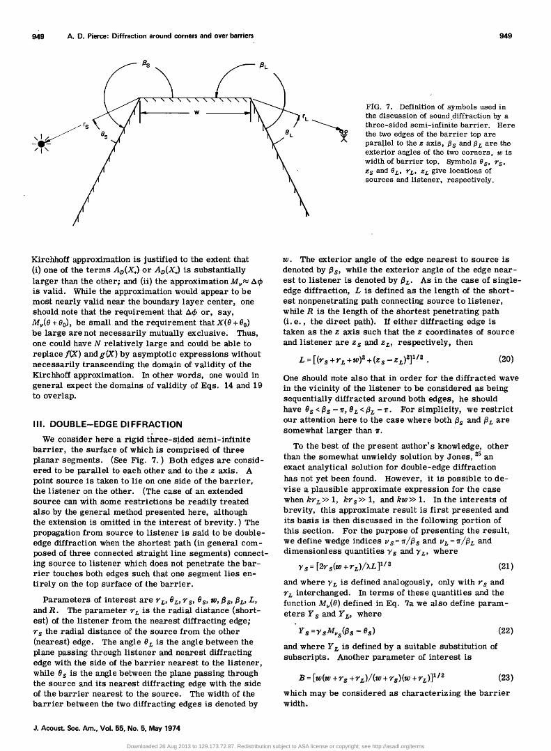
x• x x •L 8 rL W FiG. 7. Definition of symbols used in the discussion of sound diffraction by a three-sided semi-infinite barrier. Here
the two edges of the barrier top are parallel to the z axis, •$ and •L are the exterior angles of the two corners, w is width of barrier top. Symbols 05, rs, z$ and OL, rL, zz give locations of sources and listener, respectively.
Kirchhoff approximation is justified to the extent that (i) one of the terms Ao(X+) or Ao(X.) is substantially larger than the other; and (it) the approximation Mv• A•b is valid. While the approximation would appear to be most nearly valid near the boundary layer center, one should note that the requirement that A•b or, say, My(8 +80), be small and the requirement that X(8 be large are not necessarily mutually exclusive. Thus, one could have N relatively large and could be able to replace f(X) and g(X) by asymptotic expressions without necessarily transcending the domain of validity of the Kirchhoff approximation. In other words, one would in general expect the domains of validity of Eqs. 14 and 19 to overlap.
III. DOUBLE-EDGE DIFFRACTION
We consider here a rigid t•ree-sided semi-infinite barrier, the surface of which is comprised of three planar segments. (See Fig. 7. ) Both edges are consid- ered to be parallel to each other and to the z axis. A point source is taken to lie on one side of the barrier, the listener on the other. (The case of an extended source can w{th some restrictions be readily treated also by the general method presented here, although the extension is omitted in the interest of brevity. ) The propagation from source to listener is said to be double- edge diffraction when the shortest path (in general com- posed of three connected straight line segments) connect- ing source to listener which does not penetrate the bar- rier touches both edges such that one segment lies en- tirely on the top surface of the barrier.
Parameters of interest are rr., Or., r s, 8 s, w, •s, i3r., L, and R. The parameter rr. is the radial distance (short- est) of the listener from the nearest diffraeting edge; rs the radial distance of the source from the other (nearest) edge. The angle Or. is the angie between the plane passing through listener and nearest diffraeting edge with the side of the barrier nearest to the listener, while O s is the angle between the plane passing through the source and its nearest diffraeting edge with the side of the barrier nearest to the source. The width of the
barrier between the two diffraeting edges is denoted by
w. The exterior angle of the edge nearest to source is denoted by 13s, while the exterior angie of the edge near- est to listener is denoted by l•r.. As in the case of single- edge diffraction, L is defined as the length of the short- est nonpenetrating path connecting source to listener, while R is the length of the shortest penetrating path (i.e., the direct path). If either diffracting edge is taken as the z axis such that the z coordinates of source
and listener are z s and z•;, respectively, then
œ = [(rs + + + (z s - ß (20)
One should note also that in order for the diffracted wave
in the vicinity of the listener to be considered as being sequentially diffracted around both edges, he should have 8s<13s-•,Sr.<t•r.-•. For simplicity, we restrict our attention here to the ease where both/•s and/•z are somewhat larger than •r.
To the best of the present author's knowledge, other than the somewhat unwieldy solution by Jones, •.5 an exact analytical solution for double-edge diffraction has not yet been found. However, it is possible to de- vise a plausible approximate expression for the ease when krz>> 1, krs>> 1, and kw>> 1. In the interests of brevity, this approximate result is first presented and its basis is then discussed in the following portion of this section. For the purpose of presenting the result, we define wedge indices v s = •r//•s and vr, = •r//•z and dimensionless quantities Ys and ¾L, where
•' s = [2r s(W + rr.)/XL ]•/•' (21)
and where •'r. is defined analogously, only with rs and rz interchanged. In terms of these quantities and the function Mv(O) defined in Eq. 7a we also define param- eters Y s and Yz, where
Ys =Y sM•s(19s - 8s) (22) and where Yz is defined by a suitable substitution of subscripts. Another parameter of interest is
B = [w(w + r s + rz)/(w + rs)(W + rr.)] •/a (23) which may be considered as characterizing the barrier width.
J. Acoust. Soc. Am., Vol. 55, No. 5, May 1974
Downloaded 26 Aug 2013 to 129.173.72.87. Redistribution subject to ASA license or copyright; see http://asadl.org/terms

950 A.D. Pierce: Diffraction around corners and over barriers 950
(a)
(b)
FIG. 8. Two limiting cases of double-edge diffraction whose approximate solutions are given by those for diffraction by wedges of exterior angles fir and fi$, respectively. (a) Source on extension plane of barrier top. (b) Listener on extension plane of barrier top.
In terms of the symbols introduced above, the sug- gested approximate expression for the acoustic pressure at the listener location for double-edge diffraction, given that the pressure near the source (assumed not to lie exactly on a wall) is of the form eik•/R and given that neither •z or •s are close to v, is
1) = {ie'kZ/L}[f(Y>) - iK(Y>)][f(BY<) -/g (BY<)], (24)
where Y> and Y< are the greater and smaller, respect- ively, of the quantities Ys and Yr. defined in Eq. 22 and its L subscript counterpart. The functions f(X) and g(X) are the diffraction functions defined previously in Eq. 9 and which are plotted in Fig. 4.
In the writing of Eq. 24, the primary consideration is that it reduce correctly to what are believed to be three relatively well-understood limiting cases, which are, respectively (see Fig. 8):
A. Source on extension plane of barrier top (0s=•s-•)
P = -V• [f(Y•;)-/g(Y•;)] ' (25) B. Listeneron extension plane ofbarriertop
P = • •/• ([f(Y s) - ig(Y s)] ß (26) C. Both source and listener considerably removed from extension plane of barrier top (both BY< and Y> greater than 2)
pm . (27) •'BY s Y r•
Note that Eqs. 25 and 26 follow from Eq. 24 since Ys-OorYz-O, respectively, if Os-•s-• or [see Eqs. ?a and 22] and since f(0)- ig(O)=e'i'/•/x/-•.
Equation 27 also follows from Eq. 24 since g(X) is neg- ligible compared to f(X) at large X and since f(X)- 1/ (•X) (see Eq. 11) at large X.
To demonstrate that these limiting formulas are reasonable approximations for the corresponding cases, we invoke a chain of reasoning within the general spirit of Keller's geometrical theory of diffractionß •'• Suppose first that the source lies just below the extension plane
ß -- 0+• of the barrier's top, i.e , Os 2s-•- If the second edge were not present (w-•), then the single-edge dif- fraction formulas developed in Sec. I (with •0 = •+) give the acoustic pressure just above the top surface (•= 0) as being equal to e•S/R, since in Eq. 5a for this case, p•=e•/R, X+=X.=0 +, p•=ei•/R and, in Ea. 4, the only nonzero term is Pr)tffr. Thus, we may infer that, providing the barrier is sufficiently wide, the wave im- pinging on the second diffraeting edge is just e•S/R. This, however, is the same result one would have if there were no first edge and if there were a virtual source of half the "size" [with very near field (1//2)e•k•/R] at nearly the same position as the actual source, only slightly above the extended rigid barrier top. (See Fig. 8. ) The field of this virtual source plus its image would give the e•S/R along the barrier top. With the suppo- sition that the diffracted wave on the far side of the bar-
rier is determined largely by the wavefield near the second diffraeting edge, one can accordingly approximate the field at the listener location as the singly diffracted field of a point source of half-size above one side of a semi-infinite wedge of exterior angie •z. For large krz, Eq. 5a would then apply and one would identify p• =(1/2)e•Z/L, X.=X.= Yz,O=Oz, 00=• z [note thatM(O-0o) =M•(O+0o) in this ease], ro=rs+w, r=r•:, r=• (see Eqs. 8a and 21), such that the net result is just that given in Eq. 25. (This discussion assumes that the bar- rier is perfectly rigid and that the reflection coefficient is always one, regardless 'of the angie of incidence. Of course, for any real material the reflection coefficient tends to be more nearly - 1 at grazing incidence. How- ever, for nearly rigid barriers, the transition from a reflection coefficient of nearly 1 to one of nearly - 1 occurs within a very small range of angles near grazing incidence. Thus, the limiting ease based on a perfectly rigid barrier model may be expected to be applicable to configurations only slightly different from that where the source and listener both lie on the extended plane of the top surface of the barrier. From this point of view, it does not seem unreasonable to require that a formula applicable to a wide variety of source-listener configu- rations reduce to this limit. One should, however, not necessarily expect good agreement with experimental data for real barriers in such limiting eases. )
The plausibility of the limiting ease 26 follows from the application of the principle of reciprocity to the ease of Eq. 25. One may imagine a source located at what had previously been called the listener position, charac- terized by parameters (0z, rz, zz) and a listener located at what had previously been called the source position, characterized by parameters (0s, rs, Zs). Then, if 0•;-2•;-,r, we expect the field at the new listener loca- tion (old source location) to be given by Eq. 25, only with •z, 0z;, rz, zz; interchanged with • s, 0 s, rs. Zs. If one
J. Acoust. Soc. Am., Vol. 55, No. 5, May 1974
Downloaded 26 Aug 2013 to 129.173.72.87. Redistribution subject to ASA license or copyright; see http://asadl.org/terms

951 A.D. Pierce' Diffraction around corners and over barriers 951
next interchanged the source and listener locations (such that they both occupied their original positions), one should have the same numerical value for the acoustic
pressure at the listener location in both cases. Thus, since Eq. 26 differs from Eq. 25 only in the interchange of œ and S subscripts, it should apply for the limiting case when the listener angle 0 z approaches t3 z
The plausibility of the other required limit, represented by Eq. 27, follows from two successive applications of the "large X" single-edge diffraction formula, Eq. 14, or equivalently, Eq. 5a with Av(X ) approximated by 1/(,rX). The first application is based on diffraction of sound by the first edge only and gives the acoustic pres- sure on the top as
M.(O s - ' (28) where F x is identified as [2rsrr/(X.L)] •'/•'.
Here • is the length of the shortest nonpenetrating line from the source to a point with polar coordinates r•,, z •, (r r is radial distance from first edge, z •, is dis- tance parallel to the edge) on the top of the barrier. In deriving this, we have identified •0 = 13 s - es, • = 0 and
have noted that Mrs (e0) is even in 00 and periodic with period 2t3s.
When the first diffracted wave of Eq. 28 impinges on the second edge, it gives rise to a doubly diffracted wave which may be approximately expressed by Eq. 14 with appropriate identifications of the various mathe- matical symbols. Note that the new incident wave is
just (1/2)Pr)iffr, •. The factor (1/2) comes from the supposi- tion that the first diffracted wave originates at the first diffraeting edge. Since this is on the top surface of the barrier, one would have to consider the actual wave on the top of the barrier to represent a sum of an incident wave plus an (identical)wave reflected from the top surface in the limit as the source moves from slightly above the top surface to identically on the top surface. The incident wave to be used in the single-edge diffrac- tion formulas is accordingly just half the tote wave and
Px(0, zE) in Eq. 14 is interpreted as (1/2)pr)iffr,• with replaced by z E and rr replaced by the barrier top width W.
Other identifications in Eq. 14 are that
r S +;13 r S +;13 +r L 7rL siny - =--, (29) œ Z x•
where y is the angie the incident and diffracted wave- front normals make with the second edge. The two prin- cipal radii of curvature B•. and B a of the incident wave- front at the second edge are identified as B•.= w, Ba= L. Also, one has • = 0 L, Oo=BL, such that Mv(O +•0) and Mv(O-•0) are identical. One may also note that
= +w z ' Thus the doubly diffracted wave can be expressed
I (31) x •'•'Mvz,(Oz,-i•z,)M,,s(Os -i•s) '
which, after some algebra, is readily shown to be iden- tical to the expression of Eq. 27.
As may be noted from the derivation above, a strict application of the geometrical theory of diffraction would give Eq. 27 or, equivalently, Eq. 31 rather than the ap- parently more general expression of Eq. 24. However, Eq. 31 is clearly invalid if 0 z =/•z - ,r or 0 s =/•s - ,r (lis- tener or source on extension plane of top surface of the barrier) since in these limiting cases one of the corre-
sponding functions M•t (0 z - •z) or M•_ (O s - t•s) both van- ish. Also, the Eq. 31 gives the unre•ilistic result that the amplitude of the double-diffracted wave is indepen- dent of z s . One may view our writing of Eq. 24 as an attempt to give an expression which overcomes these limitations. The attempt is successful in that it accom- plishes these objectives and in that, moreover, it re- duces to the correct limiting expressions 25 and 26 in the appropriate limits. Also, it conforms to the prin- ciple of reciprocity and, furthermore, is continuous with variations in positions of source and listener. It is not, however, analytic near points where Yz = Ys. If, how- ever, both BY z and BY s are larger than 2, the departure from an analytic function is negligible in computations to the accuracy normally employed in noise control en- gineering computations. Just how much faith one should place in the overall validity of Eq. 24 remains of course a topic for further investigation and experimentation.
IV. CRITIQUE OF THE MAEKAWA APPROXIMATION
AND A SUGGESTED ALTERNATIVE
In engineering estimates of the noise reducing quali- ties of barriers of various shapes, a common technique introduced originally by Maekawa is to consider the dif- fraction by an "equivalent" thin screen rather than the actual physical barrier. This equivalent screen (Fig. 9a) is taken to extend sufficiently far up above the actual barrier's surface that its top just barely lies within the line of sight of both source and listener. Computations of the barrier's noise reduction are then based on the
Kirchhoff approximation. The general. result is the same as implicitly expressed by Eq. 19 in the present paper. In particular, if the source is a point source, one has
where P•B is the acoustic pressure at the listener loca- tion in the absence of the barrier, R is the straight line distance from source to listener, and L is the length (B•. +x•) of the shortest path which goes from source to edge to listener.
The parameter N is the Fresnel number (L-R)/(X/2). A most convenient feature of the above expression is that, once given a general plot of the quantity fz +g•. in braces versus Fresnel number N, the computation of any barrier's noise reduction becomes trivial.
There are two general reasons for which the simple approximation suggested by Maekawa may be faulted.
J. Acoust. Soc. Am., Vol. 55, No. 5, May 1974
Downloaded 26 Aug 2013 to 129.173.72.87. Redistribution subject to ASA license or copyright; see http://asadl.org/terms

952 A.D. Pierce: Diffraction around corners and over barriers 952
j SCREENii II .
(a)
•/I EQUIV. //4 THREE-SIDED •,
y BARRIER •,• • FIG. 9. Sketches illustrating (a) a technique suggested by Maekawa for estimating the amplitude of sound diffracted by an arbitrarily shaped barrier and (b) an alternate technique of re- placing the actual barrier by a three sided semi-infinite barrier wholly contained within the actual barrier. In (a) note that height of equivalent screen is shch that top is just visible to source and listener.
One is the use of the Kirchhoff approximation (which has already been commented upon by Kurze and Anderson, and the other is the manner of construction of the equiv- alent thin screen. As noted in Sec. II, the Kirchhoff approximation is in reality a small deflection (small approximation and may be expected to be increasingly less valid the further the listener is from the edge of the shadow zone. For example, suppose the listener and source are on opposite sides of a thin rigid screen (see Fig. 10a) suchthatz=z0, r=r0, e=0, e0=2• , •=2•. If the acoustic pressure is e•'R/R in the absence of the barrier, then Eq. 5a gives, for kr>> 1,
P•- L V• •
where L = 2r. On'the other hand, the Kirchhoff approxi- mation (with N = 2L/X) gives just 1/V• times the above; and hence underestimates the pressure amplik•de by a factor of 8 '•/•' corresponding to 9 dB.
One may note, however, that the Maekawa technique could easily, be modified to use the more exact thin screen diffraction formula, (which in the context of the present paper is represented by Eq. 5a with appropriate iden- tification of the various mathematical symbols), so the use of the Kirchhoff approximation does not by itself represent a serious limitation.
As regards the replacement of a real thick barrier by an equivalent screen, it is not difficult to conceive of a situation in which Maekawa's technique would give highly erroneous results. One may consider a three-sided (two walls and a top) semi-infinite rectangular barrier with source and listener each adjacent to the walls, but on opposite sides of the barrier (Fig. 10b). The equiv-
J. Acoust. Soc. Am., Vol. 55, No. 5, May 1974
alent screen constructed according to Maekawa's tech- nique would have infinite height and, accordingly, the Maekawa technique would predict zero acoustic pres- sure at the listener location, regardless of whether one did or did not use the Kirchhoff approximation. In con- trast, the double-edge diffraction formulas listed in the preceding section would give a nonzero, albeit possibly small, value.
An alternate to the simple Maekawa approximation which might give reasonable approximate results for a wide variety of barriers is to replace the acb. ml barrier by a wedge or a three-sided barrier and to use either the single-edge or double-edge diffraction formulas de- veloped in Secs. I and III. The "equivalent" barrier could be selected such as to fall entirely within the vol- ume enclosed by the acb. ml barrier (see Fig. 9b). A preferable method to either of the two just mentioned for the case of barriers with smooth convex surfaces
might be one based on Ludwig's recent uniform approxi- mation theory 33 of wave diffraction by such surfaces, al- though the details of how one might apply Ludwig's some- what general theory to noise engineering problems un- doubtedly deserve further exposition. The scheme il- lustrated by Fig. 9b could nevertheless be used if only a rough estimation were desired. Were the barrier actually of a three-sided shape [as well may be in a num- ber of cases of interest] then Ludwig's formulation would be inapplicable.
An important question as regards the idealization of an actual barrier by one for which some approximate theoretical diffraction formulas are known is just when one may have some confidence that it leads to an under- estimate of the diffracted sound. From the standpoint of one who might be designing a barrier to achieve a
• _.....-- THIN CREEN
N• •'
• WIDE , BARRIER
',,
/ix•
(o) (b)
FIG. 10. Two limiting cases for which the Maekawa approxima- tion gives substantially incorrect predictions. Source and lis- tener on opposite sides of (a) thin rigid screen and (b) a wide rectangular barrier. In (b) the dashed lines would intersect at the top of the equivalent thin screen. The height of the screen becomes arbitrarily large when source and listener are brought close to the barrier walls.
Downloaded 26 Aug 2013 to 129.173.72.87. Redistribution subject to ASA license or copyright; see http://asadl.org/terms
953 A.D. Pierce: Diffraction around corners and over barriers 953
specified standard of noise reduction, it would be pref- erable that he employ a computation scheme that con- sistently overestimates the diffracted noise, such that he might insure that any barrier designed on the basis of his computations be a conservative design. Maekawa's simple approximation clearly does not satisfy this cri- terion since, for the examples in Fig. 10, it underesti- mates tl•e diffracted amplitudes. Whether or not the scheme represented by Fig. 9b gives conservative esti- mates remains a topic for further study. At present, the author doubts that this is universally the case, al- though he suspects that it will give higher estimates of diffracted wave amplitudes if the top of the hypothetical barrier is everywhere lower than that of the actual bar- rier and if the sides of the actual barrier coincide with
those of the hypothetical barrier. This is in accordance with the plausible conjecture that higher barriers pro- vide better shielding than shorter barriers of the same "thickness."
V. SUMMARY OF FORMULAS FOR ESTIMATING
DIFFRACTED PRESSURE AMPLITUDES
In the assessment of noise reduction from small
(ideally, point) sources by barriers, it is convenient to compare the amplitude of the diffracted pressure field with that expected at some equivalent distance L from the source were no barrier present. The distance L is taken to be the shortest (diffracted path) distance from source to listener which goes around the barrier. The square of the ratio of these quantities, in the case of single-edge diffraction, according to Eq. 5a, is givenby
PDiffr
Pat œ
2
= « {If (X.) +f (X.)] z + [g(X.)+g (X.)]z}. (33)
In the case of double-edge diffraction, the corresponding quantity may be estimated by (see Eq. 24)
I PDiffr Pat œ
2
= Ira'(Y>) +gZ(Y>)][f•'(BY<) +g•'(BY<)]. (34)
Here the various symbols in Eq. 33 are as defined in Sec. I, while those in Eq. 34 are as defined in Sec. III.
Computations of Eqs. 33 and 34 are readily feasible without the aid of a digital computer. All one needs is a plot or tabulation of the functions f and g for small to moderate arguments plus a knowledge of their asymp- totic forms, both of which are given in the present paper and which also may be extracted from the NB$ H•dbook of Mathematical Functions. 3•
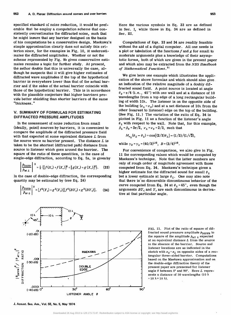
We give here one example which illustrates the appli- cation of the above formulas and which should also give. an indication of the relative magnitude of a doubly dif- fracted sound field. A point source is located at angle Os =•r/4 (i.e., 45 ø) with one wall and at a distance of 10 wavelengths from a top edge of a long rectangular build- ing of width 10X. The listener is on the opposite side of the building (zL = z s) and at a net distance of 10X from the other (nearest to listener) edge on the top of the building. (See Fig. 11.) The variation of the ratio of Eq. 34 is plotted in Fig. 11 as a function of the listener's angle 0L with respect to the wall. Note that, for this example, /3•=/3s=3V/2 , u•=Us=2/3 , such that
Mv•(O • - OL)= cos[(2/3)0•]- (1/2)/(1/V•),
while 7s = 7• = (40/3) •/z, B = (3/4) •/•' .
For convenience of comparison, we also give in Fig. 11 the corresponding values which would be computed by Maekawa's technique. Note that the latter numbers are only of rough order of magnitude agreement with those computed from Eq. 34. Maekawa's technique gives a higher estimate for_ the diffracted sound for small 0• but a lower estimate at large 0•. One may also note that there is"no discernible discontinuous behavior of the curve computed from Eq. 34 at 9L=45 ø, even though the arguments BY< and Y> are each discontinuous in deriva- tive at that particular angle.
IOX. IOX
/I
• Z
.Ol
(-2o dB)
.OOl
(- 30 d B)
.0001
(-40 dB) o*
i i ' "1 I ' i
.
,' 30* 6o* 90 ø
LISTENER ANGLE O
FIG. 11. Plot of the ratio of square of dif- fracted sound pressure amplitude PDIFFR to the square of the amplitude PAT L expected at an equivalent distance L from the source in the absence of the barrier. Source and
listener locations are as indicated in the
sketch with z$ =zœ on opposite sides of a rec- tangular three-sided barrier. Computations based on the Maekawa approximation and on the double-edge diffraction theory of the present paper are presented for listener angle 0 between 0 ø and 90 ø. Here L repre- sents a distance of 30 wavelengths (10 X +10 X+10 X).
J. Acoust. Soc. Am., Vol. 55, No. 5, May 1974
Downloaded 26 Aug 2013 to 129.173.72.87. Redistribution subject to ASA license or copyright; see http://asadl.org/terms

954 A.D. Pierce: Diffraction around corners and over barriers 954
VI. CONCLUDING REMARKS
Although the results presented are for .the case of a constant frequency source, they may in principle be used with appropriate spectral decomposition and super- position to predict the diffracted response of any source of specified time dependence. In particular, if the in- coming wave is a •andom ergodic function 34 of time, then Eqs. 33 and 34 give the ratio of the diffracted wave's spectral density to that nominally expected at distance L from the source in the barrier's absence.
Certain cautions should, however, be expressed in the application of the mathematical formulas given here. The reader- should realize in particular that the analysis is based on the idealization of a semi-infinite rigid bar- rier. Actual barriers may be absorbing and may also allow a partial transmission of energy. Also, they will of necessity be of finite extent and may rest on a partial- ly absorbing and reflecting ground. These facts do not necessarily nullify the utility of the present theory, but they do require that one exercise some judgment in the interpretation of any quantitative predictions. In this regard, it is suggested that the reader study a recent paper by Jonasson 35 which outlines a technique for taking the finite impedance of barriers into account.
Another idealization is that the propagating medium (typically, air) be homogeneous and quiescent. This is not necessarily a realistic idealization when one con- siders diffraction of sound around buildings or barriers located in the open air. The presence of an ambient wind and its associated turbulence may refract or scatter sound into the shadow zone with attendant large departures from estimates based on the homogenous atmosphere model. •6
Also, it must be emphasized that, even within the context of idealized models, the relations derived here are approximate. While the author has attemptedto point out the nature of the approximations made within the text, the mathematical complexity of the problem, especially for the case of double-edge diffraction, necessitated some departure from normal standards of mathematical rigor, and some interjection of assertions which, how- ever plausible, represent approximations whose nature is as yet incompletely understood. The general topic of sound diffraction by thick barriers thus continues to merit further analytic efforts. Pending the outcome of such investigations, the computational simplicity of the theory presented here in conjunction with what appears to be at least a more plausible theoretical basis than exists for any alternative computational scheme of com- parable simplicity presently described in the literature would appear to recommend its application as a means of obtaining tentative estimates of barrier diffraction.
ACKNOWLEDGMENTS
The research reported in this paper was supported in part by the U.S. Department of Transportation. The author would like to thank his colleagues, Richard H. Lyon and Huw Davies, for their encouragement and in- terest during the development of .the ideas presented here. The author would also like to express his apprecia-
tion for a number of helpful comments which were made by reviewers of an earlier draft of this paper. Additional helpful comments in correspondence with U. Kurze and Z. Maekawa are also gratefully acknowledged.
*Presented at the ASA-NBS Symposium on Atmospheric Acous- tics and Noise Propagation, Gaithersburg, Maryland, 27-29 September 1972.
$Present address: School of Mechanical Engineering, Georgia Institute of Technology, Atlanta, Ga. 30332.
1C. G. Gordan, W. J. Galloway, D. L. Nelson, and B. A. Kugler, "Evaluation of Highway Noise," BBN Report 1861 sub- mitted by Bolt, Beranek and Newman, Inc. to Highway Re- search Board, Engineering Division, National Academy of Sciences, Washington, D.C. (January 1970).
•'S. W. Redfearn, "Some Acoustical Source-Observer Prob- lems," Phil. Mag. 30, 223--236 (1940).
3R. O. Fehr, The Reduction of Industrial Machine Noise, Pro- ceedings of the 2rid Annual Noise Abatement Symposium (Armour Research Foundation, Chicago, 1951), pp. 93-103.
4E. J. Rathe, "Note on Two Common Problems of Sound Prop- agation," J. Sound Vib. 10,, 472-479 (1969); correction by R. M. Ellis, Sound Vib. 1•' 503-508 (1970).
5U. J. Kurze and L. L. Beranek, "Sound Propagation Out- doors," in Noise and Vibration Control, edited by L. L. Beranek (McGraw-Hill, New York, 1971), pp. 164-193.
•U. J. Kurze and G. S. Anderson, "Sound Attenuation by Bar- riers," Appl. Acoust. 4, 35-53 (1971).
vA. Sommerfeld, "Mathematische Theorie der Diffraction," Math. Ann. 47, 317-374 (1896); "Uber Verzweigte Potentiale im Raum," P. roc. Lond. Math. Soc. 27, 395-429 (1897).
8j. B. Keller, "Diffractionby an Aperture," J. Appl. Phys. 28, 426-444 (1957).
9j. B. Keller, "The Geometrical Theory of Diffraction," J. Opt. Soc. Am. 52, 116-130 (1962).
løD. S. Ahluwalia, R. M. Lewis, and J. Boersma, "Uniform Asymptotic Theory of Diffraction by a Plane Screen," SIAM J. Appl. Math. 16, 783-807 (1968).
llD. S. Ahluwalia, "Uniform Asymptotic Theory of Diffraction by the Edge of a Three Dimensional Body," SIAM J. Appl. Math. 18, 287-301 (1970).
12D. Ludwig, "Uniform Asymptotic Expansions at a Caustic," Commun. Pure Appl. Math. 19, 215-250 (1966).
13F. J. Whipple, "Diffraction by a Wedge and Kindred Prob- lems," Proc. Lond. Math. Soc. 16, 481-500 (1919).
laW. Pauli, "On Asymptotic Series for Functions in the Theory of Diffraction of Light," Phys. Rev. 54, 924-931 (1938).
15F. Oberhettinger, "On Asymptotic Series for Functions Occur- ring in the Theory of Diffraction of Waves by Wedges," J. Math. Phys. 34, 245-255 (1956).
16Z. Maekawa, "Noise Reduction by Screens," Appl. Acoust. 1, 157-173 (1968).
I?H. M. MacDonald, Electric Waves (Cambridge U. P., Cambridge, England, 1902), p. 186; "A Class of Diffraction Problems," Proc. Lond. Math. Soc. 14, 410-427 (1915).
18A. Weigrefe, "Uber einige Mehrwertige Losungen der Wel- lengleichung Au + b2u = 0 und ihre Anwendungen in der Beugungs- theorie," Ann. Phys. 39, 449-484 (1912).
19T. J. Bromwich, "Diffraction of Waves by a Wedge," Proc. Lond. Math. Soc. 14, 450-463 (1915).
2øH. S. Carslaw, "Some Multiform Solutions of the Partial Dif- ferential Equations of Physics and Mathematics and their Ap- plications," Proc. Lond. Math. Soc. 30, 121-163 (1899).
21H. S. Carslaw, "Diffraction of Waves by a Wedge of any Angle," Proc. Lond. Ma•h. Soc. 18, 291-306 (1920).
•'•'F. Oberhettinger, "Diffraction of Waves by a Wedge," Com- mun. Pure Appl. Math. 7, 551-564 (1954).
•.3j. j. Bowman and T. B. A. Senior, "The Wedge," Chap. 6 in Electromagnetic and Acoustic Scattering by Simple Shapes,
J. Acoust. Soc. Am., Vol. 55, No. 5, May 1974
Downloaded 26 Aug 2013 to 129.173.72.87. Redistribution subject to ASA license or copyright; see http://asadl.org/terms

955 A.D. Pierce: Diffraction around corners and over barriers 955
edited by J. J. Bowman, T. B. A. Senior, and P. L. E. Uslenghi [North-Holland, Amsterdam, 1969], pp. 252-283.
24j. B. Keller and A. Blank, "Diffraction and Reflection of Pulses by Wedges and Corners," Commun. Pure Appl. Math. 4, 75-95 (1951).
2•D. S. Jones, "Diffraction by a Thick Semi-Infinite Plate," Proc. R. Soc. A 217, 153-175 (1953).
•Z. Maekawa, F. Fujiwara, N. Nagano, and M. Morimoto, "Some Problems on Noise Reduction by Barriers, "Paper No. 4.8 from Symposium on Noise Prevention, Miskolc, Hungary, 37-30 August 1971, pp. 4.8.1-4.8.6.
•7j. B. Keller, "A Geometrical Theory of Diffraction," in Cal- culus of Variations and its Applications, Proceedings of Sym- posia in Applied Math., edited by L. M. Graves (McGraw- Hill, New York, 1958), Vol. 8, pp. 27-52.
•SD. L. Hutchins and R. G. Kouyoumijan, "Calculation of the Field of a Baffled Array by the Geometrical Theory of Dif- fraction," J. Acoust. Soc. Am. 45, 485-492 (1969).
29D. Blokhintzev, "The Propagation of Sound in an Inhomoge- neous Moving Medium," J. Acoust. Soc. Am. 18, 322-334 (1946).
3øG. F. Carrier, M. Krook, and C. E. Pearson, Functions of a Complex Variable: theory and technique (McGraw-Hill, New York, 1966), pp. 241-283.
31W. Gautschi, "Error Function and Fresnel Integrals," in Handbook of Mathematical Functions, edited by M. Abram- owitz and I. A. Stegun (Dover, New York, 1965), pp. 295-329.
32R. N. Buchal and J. B. Keller, "Boundary Layer Problems in Diffraction Theory," Commun. Pure Appl. Math. 13, 783- 807 (1960).
33D. Ludwig, "Uniform Asymptotic Expansion of the Field Scat- tered by a Convex Object at High Frequencies," Commun. Pure Appl. Math. 20, 103-138 (1967).
34S. H. Crandall and W. D. Mark, Random Vibration in Mech- anical Systems (Academic, New York, 1963), pp. 27-34, 71.
35H. G. Jonasson, "Diffraction by Wedges of Finite Acoustic Impedance with Application to Depressed Roads," J. Sound Vib. 25, 577-585 (1972).
36K. U. Ingard, "Interaction of Sound and Fluid Flow," paper presented at ASA-NBS Symposium on Atmospheric Acoustics and Noise Propagation, Gaithersburg, Maryland, 27 Sept. 1972.
J. Acoust. Soc. Am., Vol. 55, No. 5, May 1974
Downloaded 26 Aug 2013 to 129.173.72.87. Redistribution subject to ASA license or copyright; see http://asadl.org/terms