Embed Size (px)
Citation preview
Journal of Constructional Steel Research 72 (2012) 61–74
Contents lists available at SciVerse ScienceDirect
Journal of Constructional Steel Research
Development of a consistent buckling design procedure for tapered columns
Liliana Marques a,⁎, Andreas Taras b, Luís Simões da Silva a, Richard Greiner b, Carlos Rebelo a
a ISISE, Department of Civil Engineering, University of Coimbra, Coimbra, Portugalb Graz University of Technology, Institute for Steel Structures, Graz, Austria
⁎ Corresponding author at: Department of Civil EnginPolo II, Pinhal de Marrocos, 3030-290 Coimbra, Portufax: +351 239 797217.
E-mail address: [email protected] (L. Marques).
0143-974X/$ – see front matter © 2011 Elsevier Ltd. Aldoi:10.1016/j.jcsr.2011.10.008
a b s t r a c t
a r t i c l e i n f oArticle history:Received 15 June 2011Accepted 6 October 2011Available online 17 November 2011
Keywords:StabilityEurocode 3Non-uniform membersTapered columnsFEMSteel structures
EC3–EN 1993-1-1 provides several methodologies for the stability verification of members and frames.When dealing with the verification of non-uniform members in general, with tapered cross-section, irregulardistribution of restraints, non-linear axis, castellated, etc., the code mentions the possibility of carrying out averification based on 2nd order theory; however, several difficulties are noted when doing so, in particularwhen the benefit of plasticity should be taken into consideration.Other than this, there are yet no guidelines on how to apply standardized, easily reproducible rules as thosecontained in Section 6.3.1 to 6.3.3 of the code to non-uniform members. As a result, practical safety verifica-tions for these members are often carried out using conservative assumptions, not accounting for the advan-tages non-uniform members provide. In this paper, firstly, available approaches for the stability verificationof non-uniform members are discussed. An Ayrton–Perry formulation is then derived for the case of non-uniform columns. Finally, and followed by a numerical parametric study covering a range of slenderness,cross-sections and fabrication process, a design proposal is made for the relevant case of in-plane flexuralbuckling of linearly tapered columns subject to constant axial force. The proposal is consistent with currentrules for uniform columns provided in EC3-1-1, i.e., clause 6.3.1.
© 2011 Elsevier Ltd. All rights reserved.
1. Introduction
The stability of uniform members in EC3-1-1 [1] is checked by theapplication of clauses 6.3.1— stability of columns; clause 6.3.2— stabilityof beams and clause 6.3.3 — interaction formulae for beam-columns.
Regarding the stability of a tapered member, clauses 6.3.1 to 6.3.3do not apply and verification should be performed either by a cross-sectional verification based on second-order internal forces or, withsome difficulties, according to clause 6.3.4 (the so-called “GeneralMethod”, see [2,3]). Alternatively, as the most advanced but oftenpractically not feasible variant, the resistance may also be checkedby a numerical analysis that accounts for (geometrical and/or material)imperfections and (material and/or geometrical) nonlinearities, hence-forth denoted as GMNIA.
However, for the “General Method”, several difficulties are notedfor the verification of a non-uniform member [4]. These are:(i) shape and magnitude of imperfections (geometrical and materi-al); (ii) choice of an appropriate buckling curve and, as a result, ofan adequate imperfection factor; (iii) definition of cross-sectionclass; (iv) determination of cross-section properties for verification(or critical design location) — this problem also exists with respectto the application of clauses 6.3.1 to 6.3.3. For the application of
eering, University of Coimbra,gal. Tel.: +351 239 797260;
l rights reserved.
advanced numerical analysis (GMNIA), besides the lack of guidanceconcerning the shape and magnitude of imperfections, the volumeof work is still incompatible with practical application and a highlyexperienced engineer is required [5]. Moreover, there are no guide-lines yet to overcome any of these issues.
In this paper, the case of columns subject to in-plane bucklingwith varying cross-section and with constant axial force is studied.It is the purpose of this paper to: (i) discuss the current difficultiesin performing stability verification of non-uniformmembers; (ii) pre-sent the theoretical background for non-uniform columns; (iii) carryout a parametric study of FEM numerical simulations of non-uniformcolumns; and (iv) develop a proposal for the stability verification ofin-plane buckling of tapered columns with constant axial force.
2. Available approaches for the stability verification ofnon-uniform members
2.1. General
Fig. 1(a) and (b) illustrates recent examples of the use of curvedand tapered members or members with polygonal centroidal axis.The evaluation of the buckling resistance of suchmembers lies outsidethe range of application of the interaction formulae of EC3-1-1 andraises some new problems to be solved.
Firstly, taking as an example the case of beam-columns (uniformor not) with varying ratios of MEd to NEd over the member length,the cross-sectional classification changes from cross-section to cross-

Notations
A Cross-section areaE Modulus of elasticityFEM Finite Element MethodGMNIA Geometrical and Material Non-linear Analysis with
ImperfectionsImin Minimum 2nd moment of areaIy,eq Equivalent 2nd moment of area, y-y axisL Member lengthLeq Equivalent Member lengthLEA Linear Eigenvalue AnalysisMEd Design bending momentMR Resistant bending momentMy,Ed Design bending moment, y-y axisNEd Design normal forceNconc Concentrated axial forceNcr,tapered Elastic critical force of the tapered columnNpl Plastic resistance to normal force at a given cross-sectionNR Resistant normal forceQ Shear forcea, b Auxiliary terms for application of proposedmethodologya,b,c,d Class indexes for buckling curvesb Cross section widthbmax Maximum cross section widthbmin Minimum cross section widthe0 Maximum amplitude of a member imperfectionfy Yield strengthh Cross section heighthmax Maximum cross section heighthmin Minimum cross section heightn(x) Distributed axial force;nEd(x) Design distributed axial force;tf Flange thicknesstw Web thicknessx-x Axis along the memberx0 First order failure cross-section (with h=hmin)xc Location of the critical cross-sectiony-y Cross-section axis parallel to the flangesy (x) Displacement at a given positiony0 (x) Initial imperfectionycr(x) Critical displacement at a given positionz-z Cross-section axis perpendicular to the flangesα, αEC3 Imperfection factor according to EC3-1-1αb Load multiplier which leads to the flexural buckling
resistance of the columnαcr Load multiplier which leads to the elastic critical
resistanceβ Generalized imperfection factor accounting for taper-
ing of the memberγ Taper ratioε Utilization ratio at a given cross-sectionεM Utilization ratio regarding the bending moment M the
at a given cross-sectionεN Utilization ratio regarding the axial force N at a given
cross-sectionη Generalized imperfectionη″ CurvatureηEC3, ηuniform Generalized imperfection for the prismatic mem-
ber (considering cross-section properties at the criti-cal position)
ηnon-uniform
Generalized imperfection for the tapered memberηnum Generalized imperfection (numerical)
�λ xð Þ Non-dimensional slenderness at a given position�λy Non-dimensional slenderness for flexural buckling, y-y
axisξ. η Rectangular coordinates, longitudinal and transversalχ(x) Reduction factor at a given positionχnum Reduction factor (numerical)
62 L. Marques et al. / Journal of Constructional Steel Research 72 (2012) 61–74
section, see the example of Fig. 2. On the safe side, an elastic verifica-tion considering class 3 cross-section is likely to be performed al-though a qualitative analysis of the example shows that the stressesin the interval corresponding to class 3 cross-section are not criticalcompared to the stresses in the remainder of the member.
Secondly, the determination of an adequate buckling curve is alsonecessary and leads to inconsistencies, such as:
(i) The buckling curves in the code are geared towards specificbuckling cases. That is why the interaction formulae and coef-ficients for uniform members have to take into account thetransitions from one failure mode to the other (flexural buck-ling to lateral–torsional buckling, etc.) The “general method”can only treat these transitions in a very superficial way, by in-terpolation (not recommended by [7]) or, on the other hand,by a time-consuming specific calibration, not practical;
(ii) If the method is applied to a tapered member, the question alsoarises of how to categorize the member in terms of buckling
(a) Curved and tapered elements – BarajasAirport, Madrid, Spain
(b) Members with polygonal centroidal axis (stairs) –Italy pavilion, World Expo 2010 – Shanghai
Fig. 1. Non-uniform elements.Pictures obtained from [6)
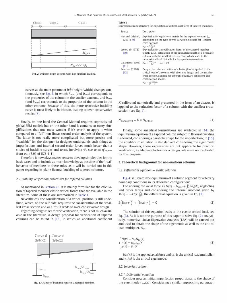
Table 1Expressions from literature for calculation of critical axial force of tapered members.
Source Description
Hirt and Crisinel,(2001) [9]
Expression for equivalent inertia for the tapered column, Ieq,depending on the type of web variation. Suitable for I-shapedcross-sections.Ncr ¼ π2EIy;eq
L2
Lee et. al (1972)[10]
Expression for a modification factor of the tapered memberlength, g, i.e., calculation of the equivalent length of a prismaticcolumn with the smallest cross-section which leads to thesame critical load. Suitable for I-shaped cross-sections.
Galambos (1998)[11]
Ncr ¼ π2EIy;min
Leq2; Leq ¼ g⋅L
Petersen (1980)[12]
Design charts for extraction of a factor β to be applied to thecritical load of a column with the same length and the smallestcross-section. Suitable for different boundary conditions andcross-section shapes.Ncr ¼ 1
β2π2EImin
L2
Class 3 Class 2 Class 1
My,Ed
NEd <<< Afy
Fig. 2. Uniform beam-column with non-uniform loading.
63L. Marques et al. / Journal of Constructional Steel Research 72 (2012) 61–74
curves as the main parameter h/b (height/width) changes con-tinuously, see Fig. 3, in which hmin (and bmin) corresponds tothe properties of the column in the smaller extreme, and hmax
(and bmax) corresponds to the properties of the column in theother extreme. Because of this, the more restrictive bucklingcurve is most likely to be chosen, leading to over conservativeresults [8].
Finally, on one hand the General Method requires sophisticatedglobal FEM models but on the other hand it contains so many sim-plifications that one must wonder if it's worth to apply it whencompared to a “full” non-linear second-order analysis of the system.The latter is not really more complicated but more precise and“readable” for the designer (a designer understands such things asimperfections and internal second-order forces much better than achoice of buckling curves and terms involving y″, see term η″cr,max
from eq. (5.9) of EC3-1-1).Therefore it nowadays makes sense to develop simple rules for the
basic cases and to include as much knowledge as possible of the “real”behavior of members in these rules, as it will be carried out in thispaper regarding in-plane flexural buckling of tapered columns.
2.2. Stability verification procedures for tapered columns
As mentioned in Section 2.1, it is mainly formulae for the calcula-tion of tapered member elastic critical forces that are available in theliterature. Some of these are summarized in Table 1.
Nevertheless, the consideration of a critical position is still unde-fined, which, on the safe side, requires the consideration of the smal-lest cross-section and as a result leads to over-conservative design.
Regarding design rules for the verification, there is not much avail-able in the literature. A design proposal for verification of taperedcolumns can be found in [13], in which an additional coefficient
Curve d(h/b>2)
Curve c(h/b≤2)
hmax
bmax
bmin≤bmax
hmin≤hmax
Fig. 3. Change of buckling curve in a tapered member.
K, calibrated numerically and presented in the form of an abacus, isapplied to the reduction factor of a column with the smallest cross-section (see Eq. 1):
Nb;rd;Tapered ¼ K � Nb;rd;Min ð1Þ
Finally, some analytical formulations are available: in [14] theequilibrium equation of a tapered column subject to flexural bucklingis derived, considering a parabolic shape for the imperfection; in [15],the equilibrium equation is also derived, considering the eigenmodeshape. However, these expressions are not applicable for practicalverification, as adequate factors for a design rule were not calibratedfor this purpose.
3. Theoretical background for non-uniform columns
3.1. Differential equation — elastic solution
Fig. 4: illustrates the equilibrium of a column segment for arbitraryboundary conditions in its deformed configuration:
Considering the axial force as N xð Þ ¼ Nconc þ ∫Lxn ξð Þdξ, neglecting
2nd order terms and considering the internal moment given byM xð Þ ¼ −EI xð Þ d2ydx2, the differential equation is given in Eq. (2):
E I xð Þ⋅y″� �
″ þ N xð Þ⋅y′� �
′ ¼ 0 ð2Þ
The solution of this equation leads to the elastic critical load, seeEq. (3). As it is not the purpose of this paper to solve Eq. (2) analyti-cally, numerical Linear Eigenvalue Analysis (LEA) will be carried outand used to obtain the shape of the eigenmode as well as the criticalload multiplier, αcr.
N xð Þ ¼ αcrNEd xð Þn xð Þ ¼ αcrnEd xð Þy xð Þ ¼ ycr xð Þ
8<: ð3Þ
NEd(x) is the applied axial force and αcr is the critical loadmultiplier,and ycr(x) is the critical eigenmode.
3.2. Imperfect column
3.2.1. Differential equationConsider now an initial imperfection proportional to the shape of
the eigenmode (ycr(x)). Considering a similar approach to paragraph

n(x)
Nconc
x
x
y
dxdx
dMM +
dxdx
dNN +
M
N
Q
dx
dxdx
dQQ +
dy
A
B
n(x)
y
dx
dy
B
n(x)
A
ξη
(a) Non-uniform column (b) Equilibrium of forces (c) Detail regarding distributed force
Fig. 4. Equilibrium of a column segment.
64 L. Marques et al. / Journal of Constructional Steel Research 72 (2012) 61–74
3.1 and assuming that the internal forces are independent of theimperfection, the differential equation, Eq. (2), becomes
EI xð Þy″� �
″ þ N xð Þy′ þ N xð Þy′0� �
′ ¼ 0 ð4Þ
Defining N(x)=αbNEd(x), where αb is the load multiplier whichleads to the flexural buckling resistance of the column, the solutionto Eq. (4) is given by
y xð Þ ¼ αb
αcr−αby0 xð Þ ð5Þ
This leads to a second order bending moment of
M xð Þ ¼ −EI xð Þy″ xð Þ ¼ −EI xð Þ αb
αcr−αby0
″ xð Þ� �
ð6Þ
Defining the utilization ratio ε as the ratio between the appliedforces and the corresponding, and considering a linear interaction be-tween moment and axial force, the utilization ratio at each section ofthe column is given by
ε xð Þ ¼ αbNEd xð ÞNR xð Þ þ M xð Þ
MR xð Þ ¼αbNEd xð ÞNR xð Þ þ
EI xð Þ αbαcr−αb
−y0″ xð Þ
� �h iMR xð Þ ð7Þ
As a result, considering a first yield criterion, for a certain load mul-tiplier αb, the utilization ratio attains a maximum of ε=1 at the criticalposition of the column, xc. As only one equation is given (Eq. (7)), buttwo variables are unknown (αb and xc), an iterative procedure is neededto obtain the solution.
3.2.2. Assumptions for the magnitude of the imperfectionAs already mentioned, a similar derivation was carried out in [15]
applicable to flexural buckling in general, in which, for the magnitudeof the initial imperfection, equation (5.9) of EC3-1-1 was considered.It will be shown in this section that this assumption leads to an ex-pression matching clause 6.3.1 of EC3-1-1 for uniform columns atthe critical position. This topic will be further discussed in this paper.
Two cases are then considered for the proportionality factor of theeigenmode deformed shape:
a) Imperfection consistent with the derivation of the column buck-ling curves — the amplitude of this deflection is given by e0;
b) Imperfection according to equation (5.9) of EC3-1-1 (equivalentgeometric imperfection) — the amplitude of the critical mode isgiven multiplied by e0 and an additional factor. This derivationmay be found in [15];
In the above, e0 denotes the maximum amplitude of a memberimperfection.
3.2.2.1. Imperfection consistent with European column buckling curvesformulation. Following a similar approach as for the derivation of theEuropean Column Buckling Curves, the imperfection is given by
y0 xð Þ ¼ ycr xð Þe0 ð8Þ
The utilization ratio ε considering this imperfection can now bederived
ε xð Þ ¼ αbNEd xð ÞNR xð Þ þ M xð Þ
MR xð Þ ¼αbNEd xð ÞNR xð Þ þ
EI xð Þ αb
αcr−αb⋅ −1ð Þ y″cr xð Þe0
� �−y″0
24
35
MR xð Þð9Þ
Considering
�λ xð Þ ¼ffiffiffiffiffiffiffiffiffiffiffiffiffiffiffiffiffiffiffiffiffiffiffiffiffiffiffiffiNR xð Þ=NEd xð Þ
αcr
s;χ xð Þ ¼ αb
NR xð Þ=NEd xð Þ ð10Þ
After some manipulations and reorganizing terms, the utilizationratio ε becomes (Eq. (11)):
ε xð Þ ¼ χ xð Þ þ χ xð Þ⋅ 11− αb
αcr
e0NR xcð ÞMR xcð Þ
� � EI xð Þ −y″cr xð Þ� �
NEd xð Þαcr
24
35 NR xð Þ
NR xcð ÞMR xcð ÞMR xð Þ
� �
ð11Þ
At the position x=xc, ε(xc)=1,
ε xcð Þ ¼ 1 ¼ χ xcð Þ þ χ xcð Þ1−�λ2 xcð Þχ xcð Þ e0
NR xcð ÞMR xcð Þ
� � EI xcð Þ: −y″cr xcð Þ� �
αcr :NEd xcð Þ
24
35 ð12Þ
Considering
e0NR xcð ÞMR xcð Þ
� �¼ αEC3
�λ xcð Þ−0:2� � ð13Þ
where αEC3=αEC3(xd).
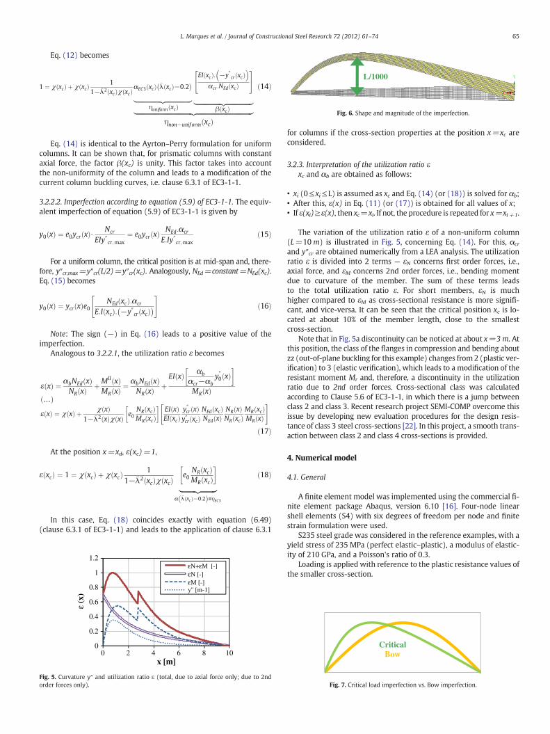
L/1000
Fig. 6. Shape and magnitude of the imperfection.
65L. Marques et al. / Journal of Constructional Steel Research 72 (2012) 61–74
Eq. (12) becomes
1 ¼ χ xcð Þ þ χðxcÞ1
1−�λ2 xcð Þχ xcð ÞαEC3 xcð Þ �λ xcð Þ−0:2� �
|fflfflfflfflfflfflfflfflfflfflfflfflfflfflfflfflfflffl{zfflfflfflfflfflfflfflfflfflfflfflfflfflfflfflfflfflffl}ηuniform xcð Þ
EI xcð Þ: −y″cr xcð Þ� �
αcr:NEd xcð Þ
24
35
|fflfflfflfflfflfflfflfflfflfflfflfflfflfflfflfflfflfflffl{zfflfflfflfflfflfflfflfflfflfflfflfflfflfflfflfflfflfflffl}|fflfflfflfflfflfflfflfflfflfflfflfflfflfflfflfflfflfflfflfflfflfflfflfflfflfflfflfflfflfflfflfflfflfflfflfflfflfflfflfflfflffl{zfflfflfflfflfflfflfflfflfflfflfflfflfflfflfflfflfflfflfflfflfflfflfflfflfflfflfflfflfflfflfflfflfflfflfflfflfflfflfflfflfflffl}β xcð Þηnon−unif orm xcð Þ
ð14Þ
Eq. (14) is identical to the Ayrton–Perry formulation for uniformcolumns. It can be shown that, for prismatic columns with constantaxial force, the factor β(xc) is unity. This factor takes into accountthe non-uniformity of the column and leads to a modification of thecurrent column buckling curves, i.e. clause 6.3.1 of EC3-1-1.
3.2.2.2. Imperfection according to equation (5.9) of EC3-1-1. The equiv-alent imperfection of equation (5.9) of EC3-1-1 is given by
y0 xð Þ ¼ e0ycr xð Þ⋅ Ncr
EIy″cr;max¼ e0ycr xð Þ NEd:αcr
E:Iy″cr;maxð15Þ
For a uniform column, the critical position is at mid-span and, there-fore, y″cr,max=y″cr(L/2)=y″cr(xc). Analogously, NEd=constant=NEd(xc).Eq. (15) becomes
y0 xð Þ ¼ ycr xð Þe0NEd xcð Þ:αcr
E:I xcð Þ: −y″cr xcð Þ� �" #
ð16Þ
Note: The sign (−) in Eq. (16) leads to a positive value of theimperfection.
Analogous to 3.2.2.1, the utilization ratio ε becomes
ε xð Þ ¼ αbNEd xð ÞNR xð Þ þMII xð Þ
MR xð Þ ¼αbNEd xð ÞNR xð Þ þ
EI xð Þ αb
αcr−αby″0 xð Þ
� �MR xð Þ
…ð Þε xð Þ ¼ χ xð Þ þ χ xð Þ
1−�λ2 xð Þχ xð Þ e0NR xcð ÞMR xcð Þ
� �EI xð ÞEI xcð Þ
y″cr xð Þy″cr xcð Þ
NEd xcð ÞNEd xð Þ
NR xð ÞNR xcð Þ
MR xcð ÞMR xð Þ
" #
ð17Þ
At the position x=xd, ε(xc)=1,
ε xcð Þ ¼ 1 ¼ χ xcð Þ þ χ xcð Þ 11−�λ2 xcð Þχ xcð Þ e0
NR xcð ÞMR xcð Þ
� �|fflfflfflfflfflfflfflfflffl{zfflfflfflfflfflfflfflfflffl}
α �λ xcð Þ−0:2ð Þ≡ηEC3
ð18Þ
In this case, Eq. (18) coincides exactly with equation (6.49)(clause 6.3.1 of EC3-1-1) and leads to the application of clause 6.3.1
0
0.2
0.4
0.6
0.8
1
1.2
0 2 4 6 8 10
ε (x
)
x [m]
εN+εM [-]εN [-]εM [-]y'' [m-1]
Fig. 5. Curvature y″ and utilization ratio ε (total, due to axial force only; due to 2ndorder forces only).
for columns if the cross-section properties at the position x=xc areconsidered.
3.2.3. Interpretation of the utilization ratio εxc and αb are obtained as follows:
• xi (0≤xi≤L) is assumed as xc and Eq. (14) (or (18)) is solved for αb;• After this, ε(x) in Eq. (11) (or (17)) is obtained for all values of x;• If ε(xi)≥ε(x), then xc=xi. If not, the procedure is repeated for x=xi+1.
The variation of the utilization ratio ε of a non-uniform column(L=10 m) is illustrated in Fig. 5, concerning Eq. (14). For this, αcr
and y″cr are obtained numerically from a LEA analysis. The utilizationratio ε is divided into 2 terms — εN concerns first order forces, i.e.,axial force, and εM concerns 2nd order forces, i.e., bending momentdue to curvature of the member. The sum of these terms leadsto the total utilization ratio ε. For short members, εN is muchhigher compared to εM as cross-sectional resistance is more signifi-cant, and vice-versa. It can be seen that the critical position xc is lo-cated at about 10% of the member length, close to the smallestcross-section.
Note that in Fig. 5a discontinuity can be noticed at about x=3 m. Atthis position, the class of the flanges in compression and bending aboutzz (out-of-plane buckling for this example) changes from2 (plastic ver-ification) to 3 (elastic verification), which leads to a modification of theresistant moment Mr and, therefore, a discontinuity in the utilizationratio due to 2nd order forces. Cross-sectional class was calculatedaccording to Clause 5.6 of EC3-1-1, in which there is a jump betweenclass 2 and class 3. Recent research project SEMI-COMP overcome thisissue by developing new evaluation procedures for the design resis-tance of class 3 steel cross-sections [22]. In this project, a smooth trans-action between class 2 and class 4 cross-sections is provided.
4. Numerical model
4.1. General
A finite element model was implemented using the commercial fi-nite element package Abaqus, version 6.10 [16]. Four-node linearshell elements (S4) with six degrees of freedom per node and finitestrain formulation were used.
S235 steel grade was considered in the reference examples, with ayield stress of 235 MPa (perfect elastic–plastic), a modulus of elastic-ity of 210 GPa, and a Poisson's ratio of 0.3.
Loading is applied with reference to the plastic resistance values ofthe smaller cross-section.
CriticalBow
Fig. 7. Critical load imperfection vs. Bow imperfection.

0.5 fy
0.5 fy
0.5 fy 0.8h
0.2b
fy
0.25 fy
(a) Hot Rolled (h/b ≤ 1.2) (b) Welded
Fig. 8. Residual stresses: + Tension and − Compression.
Fig. 9. Fabrication procedure for hot-rolled tapered elements.
Table 2Analysis of the shape of the imperfection.
Taper ratiohmax/hmin (≡bmax/bmin)
Axial force αb,GMNIA Diff(%)
Critical Bow
1 Concentrated 0.0505 0Distributed 0.0935 0.0938 −0.32
3 Concentrated 0.2496 0.2522 −1.04Distributed 0.3495 0.3635 −4.01
5 Concentrated 0.5211 0.5462 −4.82Distributed 0.6454 0.7050 −9.23
66 L. Marques et al. / Journal of Constructional Steel Research 72 (2012) 61–74
Table 3Parametric study.
Taperratio γ
Reference cross-section(i.e. with hmin, at x=x0)
Reference columnslenderness �λ x0ð Þ ¼
ffiffiffiffiffiffiffiffiffiffiffiffiffiffiffiffiffiffiNR x0ð Þ=NEd
αcr
q Fabricationprocedure
1 … 8 IPE 200 (h=200mm;b=100mm; tf=19mm;tw=11mm)
0 … 3 WeldedHot-rolled(0.5 fy)
HEB 300(h=b=300mm;
4.2. Geometrical imperfections
Regarding global imperfections, a geometrical imperfection pro-portional to the eigenmode deflection is considered with a maximumvalue of L/1000 (Fig. 6). This is consistent with the values consideredduring the development of the European column buckling curves [17]:
y0 xð Þ ¼ ycr xð Þe0 ¼ ycr xð Þ L1000
ð19Þ
The difference between considering either bow or eigenmode im-perfections (see Fig. 7) is analyzed in Table 2. It can be observed thatthe consideration of bow imperfections leads to an over-evaluation ofresistance with the increase of the level of taper and/or the shape ofthe normal force diagram relatively to a concentrated axial force.The Taper Ratio γ is defined as the ratio between the maximumheight and the minimum height (hmax/hmin), or the maximum widthand the minimum width (bmax/bmin).
As for local imperfections, these were not considered, neither inthe numerical models, nor in the analytical models (effective cross-section properties). However, this will not influence these results as,for the analyzed cases, the critical position is always (at the most)in a class 3 zone of the column.
4.3. Material imperfections
The material imperfections, residual stress patterns correspondingboth to stocky hot-rolled (i.e. with a magnitude of 0.5fy) and weldedcross-sections were considered. Fig. 8 shows the adopted residualstress pattern.
In Fig. 9, a possible fabrication procedure for the rolled case is il-lustrated (cutting of the web along the length of the column). Thischoice allowed the direct observation of the influence of the taperby comparing buckling curves for tapered members with curves formembers without taper, but with otherwise the same residual stressdistribution (Fig. 8(a)).
5. Parametric study
5.1. Definition
Table 3 summarizes the sub-set of cases to be compared with theadvanced numerical simulations. The case of in-plane flexural buck-ling of linearly web-tapered columns subject to uniform axial forceis considered. More than 350 numerical simulations with shell ele-ments were carried out. Both GMNIA (Geometrical and MaterialNon-linear Analysis with Imperfections) numerical simulations con-strained in-plane and LEA (Linear Eigenvalue Analysis) are carriedout to provide data for application of the analytical formulationsand for calibration of necessary parameters. Table 3 summarizes theparametric study, where the Taper Ratio is defined as γ=hmax/hmin.
5.2. Methodology
Table 4 summarizes the alternative procedures to obtain the resis-tance of the tapered column:
The first two cases (a) were already described in Section 3.2.3. Re-garding the other cases (b), no iteration procedure is needed becausethe critical location xc is assumed to be known from the numericalmodel. The procedure is implemented as follows:
1. Extraction of xc from GMNIA model and of the critical load multi-plier αcr from LEA model;
2. Calculation of �λ xcð Þ ¼ffiffiffiffiffiffiffiffiffiffiffiffiffiffiffiffiffiffiffiffiffiffiffiNR xcð Þ=NEd xcð Þ
αcr
q, see Eq. (10);
3. Calculation of the generalized imperfection ηnon-uniform(xc) (whenapplicable) defined in Eq. (14) as ηnon−unif orm xcð Þ ¼ ηuniform xcð Þ �β xcð Þ ¼ αEC3 xcð Þ �λ xcð Þ−0:2
� �� EI xcð Þ: −y″cr xcð Þð Þαcr :NEd xcð Þ
� �.
4. Calculation of the reduction factor χ(xc) and finally of αb, given byαb=χ(xc).NR(xc)/NEd(xc), see see Eq. (10).
tf=19mm; tw=11mm)
100×100×10×10(h=b=100mm;tf=tw=10mm)
Table 4Considered procedures for stability verification.
Method Description
Eq. (11) (a) Solution of the equation by an iterative procedureEq. (17) (a) Solution of the equation by an iterative procedureEq. (14) (b) Direct application — xc is extracted numericallyEq. (18) (b) Direct application — xc is extracted numerically
≡Eq. (14) considering β(xc)=1EC3-1-1 ≡Eq. (14) considering xc at the smaller cross-section and β(xc)=1
or≡Eq. (18) considering xc at the smaller cross-section
GMNIA –

xc
Fig. 10. Critical position according to GMNIA analysis.
67L. Marques et al. / Journal of Constructional Steel Research 72 (2012) 61–74
Finally, concerning nonlinear numerical calculations, the maxi-mum load factor of GMNIA analysis corresponds to αb load multiplier.The critical position xc is also extracted from the numerical modelcorresponding to the element with the maximum strain at the maxi-mum load factor, αb, see Fig. 10.
Results are represented relatively to the location of the smallestcross-section, x0. Because NR(x0)=NEd, Eq. (10) becomes:
�λ x0ð Þ ¼ffiffiffiffiffiffiffiffiffiffiffiffiffiffiffiffiffiffiffiffiffiffiffiffiffiffiffiffiffiffiffiffiffiNR x0ð Þ=NEd x0ð Þ
αcr
s¼ 1ffiffiffiffiffiffiffi
αcrp ;χ x0ð Þ
¼ αb
NR x0ð Þ=NEd x0ð Þ ¼ 1→χ x0ð Þ≡αbð20Þ
0.1
0.3
0.5
0.7
0.9
1.1
0.0 0.5 1.0 1.5 2.0 2.5
αb
λy (x0)
EC3 Curve bEulerγ=1 | GMNIAγ=1 | Model
EC3 Curve bEulerγ=2.5 | GMNIAγ=2.5 | Model
EC3 Curve bEulerγ=5.0 | GMNIAγ=5.0 | Model
0.1
0.3
0.5
0.7
0.9
1.1
0.0 0.5 1.0 1.5 2.0 2.5
αb
λy (x0)
λy (x0)
0.1
0.3
0.5
0.7
0.9
1.1
0.0 0.5 1.0 1.5 2.0 2.5
αb
(a.1) γ=1
(b.1) γ=2.5
(c.1) γ=5
Fig. 11. Analytical derivation Eq. (11) against numerical calculations GMNIA. (.1) Resistance
5.3. Results
5.3.1. Accuracy of the analytical modelFig. 11 illustrates the numerical results from GMNIA analyses
against results from Eq. (11) for different Taper Ratios γ, regardingthe maximum load factor αb and the relative critical position xc/L. Acolumn consisting of the hot-rolled cross-section 100×100×10×10defined in Table 3 is chosen for illustration. Although differencesof −5% (unsafe) to 7% (safe) are noticed, it can be seen that the ana-lytical model characterizes the behavior of the tapered columnwell when compared to the numerical model. This was also foundfor other cases of Table 3 (not shown in Fig. 11). It is also noticeablean increase of up to 20% in terms of resistance with the increase of ta-pering at a slenderness range of �λ x0ð Þ ¼ 0:5 to �λ x0ð Þ ¼ 1, which showsthe relevance of Eq. (11). Eq. (11) was solved considering an imper-fection factor αEC3=0.34 (curve b of EC3-1-1), in agreement withthe adopted residual stresses of 0.5fy. Finally, in Fig. 11(a), the TaperRatio of γ=1, i.e., prismatic column, is shown for comparison. It isexpected that the relative critical location is located at mid-spanwhere the curvature is maximum and therefore xc/L=0.5 (seeFig. 11(a.2)). Moreover, Eq. (11) should give the same results as theEC3 curve b. This is visible in Fig. 11(a.1).
0.0 0.5 1.0 1.5 2.0 2.50.0
0.1
0.2
0.3
0.4
0.5
0.6
xc/L
λy (x0)
0.0 0.5 1.0 1.5 2.0 2.5 3.0
0.1
0.2
0.3
0.4
0.5
0.6
xc/L
λy (x0)
γ=1 | GMNIAγ=1 | Model
γ=2.5 | GMNIAγ=2.5 | Model
γ=5.0 | GMNIAγ=5.0 | Model
(a.2) γ=1
(b.2) γ=2.5
(c.2) γ=5
0.0
0.0 0.5 1.0 1.5 2.0 2.5 3.0
0.1
0.2
0.3
0.4
0.5
xc/L
λy (x0)
0.0
αb≡χ(x0) against slenderness �λ x0ð Þ; (.2) Critical position xc/L against slenderness �λ x0ð Þ.

0.2
0.4
0.6
0.8
1.0
0 0.5 1 1.5
γ=1 γ=1.5γ=2 γ=3γ=6 EC3-bEuler
γ=1 γ=2γ=3 γ=5γ=8 EC3-bEuler
(a) 100x100x10x10 Hot-Rolled (b) 100x100x10x10 Welded
γ=1 γ=1.25γ=1.5 γ=2γ=3 γ=5EC3-b Euler
γ =1 γ=1.33γ =2 γ=3γ =5 EC3-bEuler
(c)IPE200 Welded (d) HEB300 Welded
αb
0.2
0.4
0.6
0.8
1.0
αb
0.2
0.4
0.6
0.8
1.0
αb
0.2
0.4
0.6
0.8
1.0
αb
λy (x0)0 0.5 1 1.5
λy (x0)
0 0.5 1 1.5
λy (x0)0 0.5 1 1.5
λy (x0)
Fig. 12. Numerical calculations GMNIA organized by Taper Ratio. Resistance αb≡χ(x0) against slenderness �λ x0ð Þ.
0.4
0.6
0.8
1.0
0 1
αb
λy(x0)
No xc | No βxc | No βxc | βEC3-bGMNIAEuler
0.5 1.5
Fig. 13. Influence of the critical position and of the imperfection in the resistance of thetapered column.
68 L. Marques et al. / Journal of Constructional Steel Research 72 (2012) 61–74
5.3.2. Influence of the taper ratio, γ=hmax/hmin
Fig. 12 illustrates GMNIA results of resistance against slender-ness (based on Npl of the smallest cross-section) organized byTaper Ratio. Curve b of EC3-1-1 is shown for comparison.Note that, for the welded cross-section cases, the numericalcurve corresponding to the uniform element (γ=1) shows devia-tions that fall below the code curve results for the relevant slen-derness range up to 1. This will be discussed in Section 6 —
Verification procedure.A smooth increase in the resistance with the increase of Taper
Ratio γ along all slenderness ranges can be observed in all cases ofFig. 12. It also shows to be less significant for higher levels of TaperRatio.
5.3.3. Analysis of the critical position xc and of an additional factor β(xc)to the generalized imperfection ηuniform
The importance of identification of the critical location has alreadybeen discussed. Nowadays, there is no straight-forward procedure toobtain this location. Therefore, most designers in practice will use thesmallest cross-section properties for verification according to clause6.3.1 of EC3-1-1.
Moreover, an additional factor β(xc) derived in Section 3.2.2.1and given in Eq. (17) characterizes the increase of resistance ofthe tapered member relatively to the uniform member. This factorattains a limit for the case of uniform members, reaching unityfor those cases. When associated to the generalized imperfectionof the uniform member ηuniform to give a generalized imperfectionof the tapered member ηnon-uniform, see Eq. (14), the latter becomes
lower and, as a consequence the resistance of the tapered memberbecomes higher.
β xcð Þ ¼EI xcð Þ: −y″cr xcð Þ
� �αcr :NEd xcð Þ ð21Þ
Fig. 13 illustrates the influence of these two parameters for amemberwith an initial cross-section of 100×100×10×10 (hot-rolled) and γ=4(hmax=400mm). Table 5 shows results for the case of �λy x0ð Þ ¼ 0:74. In

0
0.1
0.2
0.3
0.4
0.5
0.6
0.7
0.8
0.9
1
0 1 2 3
β(xc)
λy(xc)
1.00
1.50
2.00
2.50
3.00
4.00
5.00
6.00
γ=
0.5 1.5 2.5 3.5
Fig. 15. Additional imperfection factorβ(xc) against the relative slenderness �λy xcð Þ, all cases.
Table 5Influence of the critical position and of the imperfection in the resistance of the taperedcolumn (�λy x0ð Þ ¼ 0:74; αcr=1.85).
Case xc/L β(xc) �λy xcð Þ χ(xc) αb=χ(xc)NRk/NEd Diff (%)
No xc | No β 0 1 0.735 0.764 0.764 17.5xc | No β 0.10 (GMNIA) 1 0.773 0.741 0.820 11.5xc | β 0.10 (GMNIA) 0.48 0.773 0.842 0.932 −0.6GMNIA 0.10 – – – 0.926 –
69L. Marques et al. / Journal of Constructional Steel Research 72 (2012) 61–74
order to obtain resistance for the cases considering xc, the numerical po-sition was considered. Moreover, to calculate β(xc), ycr is extractedfrom LEA analysis. It can be seen that factor β has a great influencein the resistance of the column. Regarding the case in which xc is con-sidered with current EC3 imperfection (no β), note that the first 3cases coincide with current EC3 buckling curve b. This happens becauseat this slenderness range and regarding this taper ratio, the 2nd orderfailure cross-section (or xc) is the same as the 1st order failure cross-section (smaller end). Table 5 shows an imperfection decrease ofmore than 50% (β(xc)=0.48) for the analyzed case of �λy x0ð Þ ¼ 0:74.
Finally, it can also be observed that the relative critical location xc/Land the additional imperfection factor β(xc) are independent of thefabrication process or of the initial cross-section proportions, seeFigs. 14 and 15, computed for all the analyzed cases.
5.3.4. Influence of the function for the magnitude of the imperfectionIn Section 3.2.2 Assumptions for the magnitude of the imperfection,
two cases are considered. Results have been shown regarding the am-plitude of the imperfection given by e0 (Section 3.2.2.1), i.e., consistentwith the derivation of the column buckling curves of EC3-1-1. Fig. 16compares the solution of Eqs. (11) and (17), in which for the latter,Eq. (16) (equation (5.9) of EC3-1-1) is considered for the imperfection.This derivation is also given in [15]. Two representations of resistanceare considered and illustrated concerning a Taper Ratio of γ=4 andthe reference cross-section 100×100×10×10 (hot-rolled): Fig. 16(a)illustrates the reduction factor �λ x0ð Þas a function of the reduction factorχ(x0)≡αb, and, therefore, resistance can be directly compared;Fig. 16(b) illustrates the reduction factor �λ xcð Þas a function of the reduc-tion factorχ(xc)— it is stated in [15] that when equation (5.9) of EC3-1-1 (Eq. (16)) is considered for the imperfection, results of the reductionfactorχ(xc) coincidewith current buckling curves for columns (see alsoFig. 16(b)) and that good agreement is achieved with numericalmodels. This is to be expected if the imperfections considered in the nu-merical models are also obtained from Eq. (16). However, and as al-ready mentioned in Section 2.2, the magnitude of the geometrical
0
0.05
0.1
0.15
0.2
0.25
0.3
0.35
0.4
0.45
0.5
0 1 1.5 2 3 3.5
xc/L
λy(x0)
1.00
1.17
1.33
1.50
2.00
3.00
5.00
8.00
γ=
2.50.5
Fig. 14. Relative critical position xc/L against the relative slenderness �λy x0ð Þ, all cases.
imperfection should only be dependent on the member length [18].Moreover, for the calibration of EC3 imperfection factors for columns,this magnitude was given by e0=L/1000 (and additional residual stres-ses for the material imperfections). The same approach is consideredin this study. Both Fig. 16(a) and (b) show a better agreement withthe EC3 consistent approach regarding Eq. (11).
Note that concerning Fig. 16(b), GMNIA is also illustrated in terms ofthe reduction factor χ(xc), in which xc is obtained from the numericalmodel. Finally, Fig. 17(a) and (b) respectively illustrate resistance αb
and relative critical location xc/L regarding all Taper Ratios of the analyzedcross-section 100×100×10×10 (hot-rolled). A higher spread is noticedfor Eq. (17).
6. Design methodology
6.1. Introduction
Considering the developed analytical formulation and the numer-ical calculations, a verification procedure for the stability of taperedcolumns subject to in-plane bending is now proposed.
In a first step, regarding the imperfection factor for uniformwelded cross-sections it was noticed that, for I-sections, the imperfec-tion factor α=0.34 provides unsafe results for slenderness up to ap-proximately 1 (differences of 8% were observed, see Fig. 12(b), (c)and (d)). Because this proposal has, as a reference limit, the case ofuniform members (γ=1), it was decided to calibrate new imperfec-tion factors for welded cross-sections for that purpose.
In a second step, the development of a verification procedure fortapered columns is done. Here, expressions for the critical locationxc and the additional imperfection factor β(xc) are calibrated againstnumerical results shown in Figs. 14 and 15.
6.2. Imperfection factors for flexural buckling of uniform welded columns
Ayrton–Perry formulation for uniform columns is given by
1 ¼ χ þ χ1
1−�λ2χe0
NR
MR
� �α �λ xcð Þ−0:2� �
≡ηEC3→ …ð Þ→ηEC3
¼ α �λ xcð Þ−0:2� � ¼ 1−�λ2χ
� �1− 1
χ
� ð22Þ
The generalized imperfection ηEC3 for in-plane buckling of uniformcolumns is given by Eq. (23), for a flange thickness tf≤100mm
ηEC3 ¼ α �λ xcð Þ−0:2� � ¼ 0:34 �λ xcð Þ−0:2
� � ð23Þ
Fig. 18(a) illustrates the generalized imperfection of EC3-1-1 ηEC3compared to the generalized imperfection ηnum of about 100

0.1
0.3
0.5
0.7
0.9
1.1
0.0 0.5 1.0
χ(x0) χ(xc)≡αb
λy (x0)
EC3 -b
Euler
GMNIA
Eq. (11)
Eq. (17)
0.1
0.3
0.5
0.7
0.9
1.1EC3 -b
Euler
GMNIA
Eq. (11)
Eq. (17)
(a) Resistance αb≡χ(x0) against slenderness (x0)λ (b) Resistance χ(xc) against slenderness (xc)λ
1.5 2.0 2.5 0.0 0.5 1.0
λy (xc)1.5 2.0 2.5
Fig. 16. Influence of imperfection magnitude — buckling curve representation.
0
0.2
0.4
0.6
0.8
1
1.2
0 0.2 0.4 0.6 0.8 1 1.2
α b (
Equ
atio
n)
αE (GMNIA)
Eq. (18)
Eq. (12)
0
0.1
0.2
0.3
0.4
0.5
0.6
0 0.1 0.2 0.3 0.4 0.5 0.6
x c/L
(Equ
atio
n)
xc/L (GMNIA)
Eq. (17)
Eq. (11)
(a) Resistance αb (b) Critical location xc/L
Fig. 17. Influence of imperfection magnitude — 100×100×10×10 (hot rolled), all Taper Ratios.
70 L. Marques et al. / Journal of Constructional Steel Research 72 (2012) 61–74
numerical calculations covering a range of uniform columnswith differ-ent h/b ratios varying from 0.95 (HEA200) to 2.5 (IPE500) and slender-ness varying from �λy ¼ 0:1 to �λy ¼ 2:0. The value ηnum is calculatedaccording to Eq. (24), see also [19], in which χ is extracted numericallyand corresponds to the maximum load factor of GMNIA calculation, αb:
ηnum ¼ 1−�λ2χnum
� �1−1
χnum
�ð24Þ
0
0.05
0.1
0.15
0.2
0.25
0.3
0.35
0.4
0.45
0.5
0.0 2.0
ηy
λy
α=0.34 (EC3)
α=0.45 (Best fit)
Cut-off
(a) Generalized imperfection η against slenderness λy
1.51.00.5
Fig. 18. Generalized imperfection of in-plan
Fig. 18(a) shows the difference, on the unsafe side, in consideringfor the imperfection factor α the value of 0.34. A value of α=0.45 wasshown to fit the reduction factor χy very accurately up to slendernessof 1. However, in order not to get too conservative for slendernessabove 1 and to take into account the buckling behavior of columnswith a welded residual stress pattern for that slenderness range,a cut-off of η ¼ α �λ−0:2
� �≤0:27was also shown to be adequate. If
the cut-off of 0.27 is applied, for higher slenderness of about�λy ¼ 1:5, imperfection becomes unsafe again. However, for high
λy
0.3
0.4
0.5
0.6
0.7
0.8
0.9
1
0.0 0.5 1.0 1.5
χy
α=0.34 (EC3)α=0.45 (Best fit)α=0.45 + Cut-offEuler
λy(b) Resistance χy against slenderness
e flexural buckling of welded columns.
0
0.1
0.2
0.3
0.4
0.5
0.6
0.7
0.8
0.9
1
β(xc)
λy(xc)0 0.5 1 1.5 2 2.5 3 3.50.2
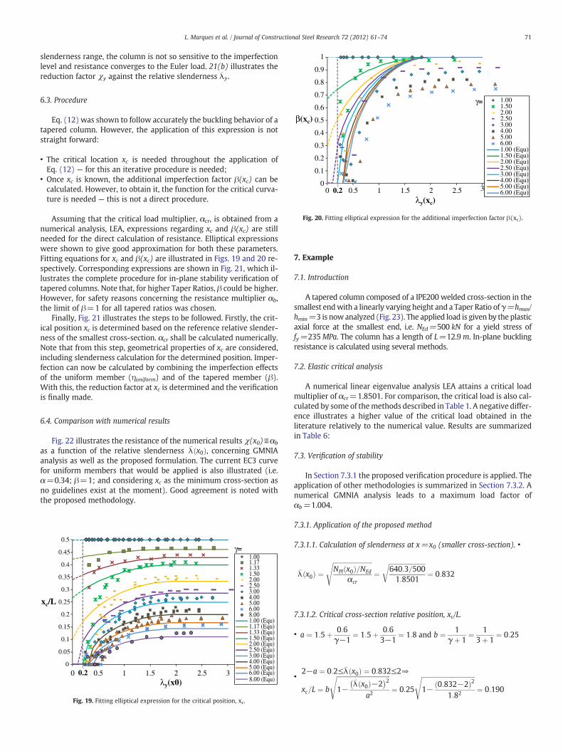
1.001.502.002.503.004.005.006.001.00 (Equ)1.50 (Equ)2.00 (Equ)2.50 (Equ)3.00 (Equ)4.00 (Equ)5.00 (Equ)6.00 (Equ)
γ=
Fig. 20. Fitting elliptical expression for the additional imperfection factor β(xc).
71L. Marques et al. / Journal of Constructional Steel Research 72 (2012) 61–74
slenderness range, the column is not so sensitive to the imperfectionlevel and resistance converges to the Euler load. 21(b) illustrates thereduction factor χy against the relative slenderness �λy.
6.3. Procedure
Eq. (12) was shown to follow accurately the buckling behavior of atapered column. However, the application of this expression is notstraight forward:
• The critical location xc is needed throughout the application ofEq. (12) — for this an iterative procedure is needed;
• Once xc is known, the additional imperfection factor β(xc) can becalculated. However, to obtain it, the function for the critical curva-ture is needed — this is not a direct procedure.
Assuming that the critical load multiplier, αcr, is obtained from anumerical analysis, LEA, expressions regarding xc and β(xc) are stillneeded for the direct calculation of resistance. Elliptical expressionswere shown to give good approximation for both these parameters.Fitting equations for xc and β(xc) are illustrated in Figs. 19 and 20 re-spectively. Corresponding expressions are shown in Fig. 21, which il-lustrates the complete procedure for in-plane stability verification oftapered columns. Note that, for higher Taper Ratios, β could be higher.However, for safety reasons concerning the resistance multiplier αb,the limit of β=1 for all tapered ratios was chosen.
Finally, Fig. 21 illustrates the steps to be followed. Firstly, the crit-ical position xc is determined based on the reference relative slender-ness of the smallest cross-section. αcr shall be calculated numerically.Note that from this step, geometrical properties of xc are considered,including slenderness calculation for the determined position. Imper-fection can now be calculated by combining the imperfection effectsof the uniform member (ηuniform) and of the tapered member (β).With this, the reduction factor at xc is determined and the verificationis finally made.
6.4. Comparison with numerical results
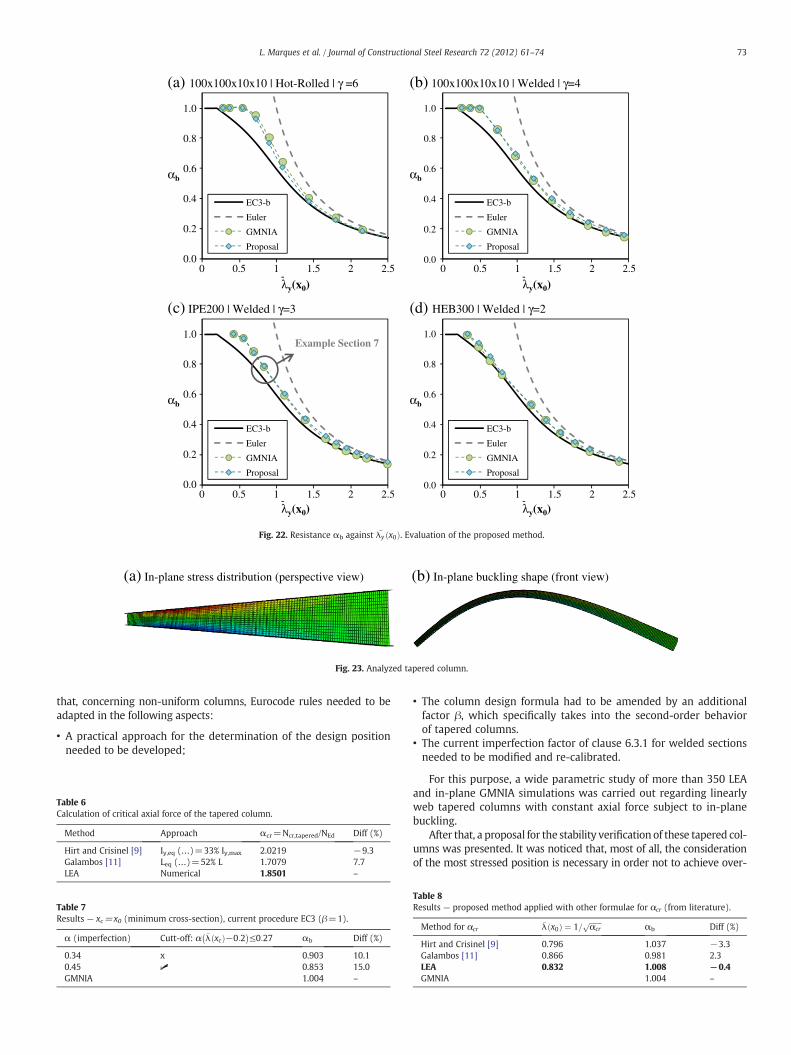
Fig. 22 illustrates the resistance of the numerical results χ(x0)≡αb
as a function of the relative slenderness �λ x0ð Þ, concerning GMNIAanalysis as well as the proposed formulation. The current EC3 curvefor uniform members that would be applied is also illustrated (i.e.α=0.34; β=1; and considering xc as the minimum cross-section asno guidelines exist at the moment). Good agreement is noted withthe proposed methodology.
0
0.05
0.1
0.15
0.2
0.25
0.3
0.35
0.4
0.45
0.5
0 1 2 3 3.5
xc/L
λy(x0)0.2
1.001.171.331.502.002.503.004.005.006.008.001.00 (Equ)1.17 (Equ)1.33 (Equ)1.50 (Equ)2.00 (Equ)2.50 (Equ)3.00 (Equ)4.00 (Equ)5.00 (Equ)6.00 (Equ)8.00 (Equ)
γ=
2.51.50.5
Fig. 19. Fitting elliptical expression for the critical position, xc.
7. Example
7.1. Introduction
A tapered column composed of a IPE200 welded cross-section in thesmallest endwith a linearly varying height and a Taper Ratio of γ=hmax/hmin=3 is nowanalyzed (Fig. 23). The applied load is given by the plasticaxial force at the smallest end, i.e. NEd=500 kN for a yield stress offy=235MPa. The column has a length of L=12.9m. In-plane bucklingresistance is calculated using several methods.
7.2. Elastic critical analysis
A numerical linear eigenvalue analysis LEA attains a critical loadmultiplier of αcr=1.8501. For comparison, the critical load is also cal-culated by some of themethods described in Table 1. A negative differ-ence illustrates a higher value of the critical load obtained in theliterature relatively to the numerical value. Results are summarizedin Table 6:
7.3. Verification of stability
In Section 7.3.1 the proposed verification procedure is applied. Theapplication of other methodologies is summarized in Section 7.3.2. Anumerical GMNIA analysis leads to a maximum load factor ofαb=1.004.
7.3.1. Application of the proposed method
7.3.1.1. Calculation of slenderness at x=x0 (smaller cross-section). •
�λ x0ð Þ ¼ffiffiffiffiffiffiffiffiffiffiffiffiffiffiffiffiffiffiffiffiffiffiffiffiffiNPl x0ð Þ=NEd
αcr
s¼
ffiffiffiffiffiffiffiffiffiffiffiffiffiffiffiffiffiffiffiffiffiffiffi640:3=5001:8501
r¼ 0:832
7.3.1.2. Critical cross-section relative position, xc/L.
• a ¼ 1:5þ 0:6γ−1
¼ 1:5þ 0:63−1
¼ 1:8 and b ¼ 1γ þ 1
¼ 13þ 1
¼ 0:25
•2−a ¼ 0:2≤�λ x0ð Þ ¼ 0:832≤2⇒ffiffiffiffiffiffiffiffiffiffiffiffiffiffiffiffiffiffiffiffiffiffiffiffiffiffiffiffiffiffiffiffiffiffi� �2s ffiffiffiffiffiffiffiffiffiffiffiffiffiffiffiffiffiffiffiffiffiffiffiffiffiffiffiffiffiffiffiffiffiffi
2s
xc=L ¼ b 1−�λ x0ð Þ−2
a2¼ 0:25 1− 0:832−2ð Þ
1:82 ¼ 0:190

Required data
Critical Position, xc
Slenderness at xc
Account for Imperfection
Reduction factor
Verification
( )
>
≤≤−−
−
≤−<
=
2)(,
2)(2,2)(
1
2.0)(2)(,0
/
0
02
20
00
xb
xaa
xb
xorax
Lxc
λ
λλ
λλ
1
1;
1
6.05.1;;
/)()( minmax
00 +
=−
+===γγ
γα
λ bahhNxN
xcr
EdRk
cr
EdcRkc
NxNx
αλ /)(
)( =
( )
>
≤≤−−
−
≤−<
=
2)(,1
2)(2,2)(
1
2.0)(2)(,0
)(2
2
c
cc
cc
c
x
xaa
x
xorax
x
λ
λλ
λλ
β
( )
27.0
45.034.0
2.0)(
≤−
−
−=
Uniform
Uniform
cUniformUniform
WeldedRolledHot
where
x
ηα
λαη
( )=
++=≤−+
=)()(
)()(15.0)(,1
)()()(
1)(
2
22cUniformc
ccc
ccc
cxx
xxxwith
xxxx
βηηληφ
λφφχ
)()()( 0xNxNxN RkcRkcEd ≤≤ χ
Fig. 21. Design proposal.
72 L. Marques et al. / Journal of Constructional Steel Research 72 (2012) 61–74
7.3.1.3. Calculation of slenderness at x=xc.
•NPl xcð Þ ¼ A xcð Þf y ¼ 740:5 kN⇒ffiffiffiffiffiffiffiffiffiffiffiffiffiffiffiffiffiffiffiffiffiffiffiffiffi
N xð Þ=Ns ffiffiffiffiffiffiffiffiffiffiffiffiffiffiffiffiffiffiffiffiffiffiffi
740:5=500r
�λ xcð Þ ¼ Pl c Ed
αcr¼
1:8501¼ 0:895
7.3.1.4. Determination of imperfection, η.
• Additional Imperfection factor β(xc)
2−a ¼ 0:5≤�λ xcð Þ ¼ 0:895≤2⇒
β xcð Þ ¼ffiffiffiffiffiffiffiffiffiffiffiffiffiffiffiffiffiffiffiffiffiffiffiffiffiffiffiffiffiffiffiffiffiffi1−
�λ xcð Þ−2� �2
a2
s¼
ffiffiffiffiffiffiffiffiffiffiffiffiffiffiffiffiffiffiffiffiffiffiffiffiffiffiffiffiffiffiffiffiffiffi1− 0:895−2ð Þ2
1:82
s¼ 0:789
• ηnon−unif orm ¼ ηuniform � β xcð Þ ¼ 0:27� 0:789 ¼ 0:213
7.3.1.5. Reduction factor at x=xc.
• ϕ xcð Þ ¼ 0:5 1þ ηþ �λ2 xcð Þ� �
¼ 0:5 1þ 0:213þ 0:8952� �
¼ 1:007
• χ xcð Þ ¼ 1
ϕ xcð Þ þffiffiffiffiffiffiffiffiffiffiffiffiffiffiffiffiffiffiffiffiffiffiffiffiffiffiffiffiffiffiffiffiϕ2 xcð Þ−�λ2 xcð Þ
q ¼ 1
1:007þffiffiffiffiffiffiffiffiffiffiffiffiffiffiffiffiffiffiffiffiffiffiffiffiffiffiffiffiffiffiffiffiffiffi1:0072−0:8952
p
¼ 0:681≤1
7.3.1.6. Verification.
• Nb;Rd ¼ χ xcð ÞNPl xcð Þ ¼ 0:681� 740:5 ¼ 504:2kN≤NPl x0ð Þ
•Nb;Rd≥NEd→504:2 > 500→Design check verified!αb ¼ Nb;Rd=NEd ¼ 504:2=500 ¼ 1:008 GMNIA;αb ¼ 1:004ð Þ
7.3.2. Summary of resultsResults are summarized in Tables 7 and 8.Firstly, from results of Section 7.3.1, the resistance calculated
according to the proposed methodology of Section 6.3 is practicallycoincident with the GMNIA resistance (0.4% of difference).
Table 7 summarizes results considering the smallest cross-section forverification. Note that, in this case, the case corresponding to α=0.34leads to a smaller difference (10%) because current buckling curves forwelded columns lead to unsafe results in this slenderness range. There-fore, the comparable correct difference is 15%, which corresponds to pro-posed buckling curve with α=0.45 considering the cut-off of η≤0.27.
Finally, considering [11] or [9] for αcr calculation leads to differentrelative slenderness �λy x0ð Þ. Considering [9] with the proposed verifi-cation procedure leads to unsafe level of resistance.
8. Conclusions
In this paper an analytical derivation of non-prismatic columns wascarried out and compared against numerical simulations. It was shown
(a) In-plane stress distribution (perspective view) (b) In-plane buckling shape (front view)
Fig. 23. Analyzed tapered column.
0.0
0.2
0.4
0.6
0.8
1.0
0 1 2
αb αb
λy(x0)
EC3-b
Euler
GMNIA
Proposal
0.0
0.2
0.4
0.6
0.8
1.0
EC3-b
Euler
GMNIA
Proposal
(a) 100x100x10x10 | Hot-Rolled | γ =6 (b) 100x100x10x10 | Welded | γ=4
EC3-b
Euler
GMNIA
Proposal
Example Section 7
EC3-b
Euler
GMNIA
Proposal
(c) IPE200 | Welded | γ=3 (d) HEB300 | Welded | γ=2
0.5 1.5 2.5 0 1 2
λy(x0)0.5 1.5 2.5
0.0
0.2
0.4
0.6
0.8
1.0
0 1 2
αb αb
λy(x0)
0.0
0.2
0.4
0.6
0.8
1.0
0.5 1.5 2.5 0 1 2
λy(x0)0.5 1.5 2.5
Fig. 22. Resistance αb against �λy x0ð Þ. Evaluation of the proposed method.
73L. Marques et al. / Journal of Constructional Steel Research 72 (2012) 61–74
that, concerning non-uniform columns, Eurocode rules needed to beadapted in the following aspects:
• A practical approach for the determination of the design positionneeded to be developed;
Table 6Calculation of critical axial force of the tapered column.
Method Approach αcr=Ncr,tapered/NEd Diff (%)
Hirt and Crisinel [9] Iy,eq (…)=33% Iy,max 2.0219 −9.3Galambos [11] Leq (…)=52% L 1.7079 7.7LEA Numerical 1.8501 –
Table 7Results — xc=x0 (minimum cross-section), current procedure EC3 (β=1).
α (imperfection) Cutt-off: α �λ xcð Þ−0:2� �
≤0:27 αb Diff (%)
0.34 x 0.903 10.10.45 ✓ 0.853 15.0GMNIA 1.004 –
• The column design formula had to be amended by an additionalfactor β, which specifically takes into the second-order behaviorof tapered columns.
• The current imperfection factor of clause 6.3.1 for welded sectionsneeded to be modified and re-calibrated.
For this purpose, a wide parametric study of more than 350 LEAand in-plane GMNIA simulations was carried out regarding linearlyweb tapered columns with constant axial force subject to in-planebuckling.
After that, a proposal for the stability verification of these tapered col-umns was presented. It was noticed that, most of all, the considerationof the most stressed position is necessary in order not to achieve over-
Table 8Results — proposed method applied with other formulae for αcr (from literature).
Method for αcr�λ x0ð Þ ¼ 1=
ffiffiffiffiffiffiffiαcr
pαb Diff (%)
Hirt and Crisinel [9] 0.796 1.037 −3.3Galambos [11] 0.866 0.981 2.3LEA 0.832 1.008 −0.4GMNIA 1.004 –

74 L. Marques et al. / Journal of Constructional Steel Research 72 (2012) 61–74
conservative levels of resistance. The above-mentioned factor βwas de-veloped based on the prior analytical formulation and calibrated withnumerical results. Finally, a new generalized imperfection for weldeduniform columnswas also calibrated in order to obtain improved resultsfor the tapered cases. The next step is to perform a reliability analysisof the proposal and determine γM1 [20,21]. Moreover, the same topicwill be analyzed for other tapering shapes and loading.
Acknowledgment
Financial support from the Portuguese Ministry of Science andHigher Education (Ministério da Ciência e Ensino Superior) under con-tract grant SFRH/BD/37866/2007 is gratefully acknowledged.
References
[1] CEN. Eurocode 3, EN-1993-1-1:2005, Eurocode 3: design of steel structures— Part1–1: general rules and rules for buildings. Brussels, Belgium: European Committeefor Standardization; 2005.
[2] Müller C (2003). “Zum Nachweis ebener Tragwerke aus Stahl gegen seitlichesAusweichen”, PhD Thesis, RWTH Aachen, Germany.
[3] Simões da Silva L, Marques L, Rebelo C. Numerical validation of the General Methodin EC3-1-1 for prismatic members. J Constr Steel Res 2010;66(4):575–90.
[4] Simões da Silva L, Gervásio H, Simões R. Design of steel structures. ECCS EurocodeDesign Manuals. ECCS Press and Ernst & Sohn; 2010.
[5] Simões da Silva L, Gervásio H. Manual de Dimensionamento de EstruturasMetálicas:Métodos Avançados. Coimbra, Portugal: cmm Press; 2007.
[6] www.steelconstruct.com, in June 16th, 2010.[7] ECCS TC8. “Resolution of ECCS/TC8 with respect to the general method in EN
1993-1-1”, ECCS TC8 Stability; 2006.
[8] Marques L, Simões da Silva L, Rebelo C. Application of the general method for theevaluation of the stability resistance of non-uniform members. Proceedings ofICASS, Hong Kong, 16–18 December; 2009.
[9] Hirt MA, Crisinel M. Charpentes Métaliques — Conception et Dimensionnement desHalles et Bâtiments. Traité de Génie Civil, vol. 11. Lausanne: Press Polytechniqueset Universitaires Romandes; 2001.
[10] Lee GC, Morrell ML, Ketter RL. Design of tapered members. Weld Res Counc BullJune 1972(173):1–32.
[11] Galambos TV, editor. Guide to Stability Design Criteria for Metal Structures. FifthEdition. John Wiley & Sons Inc.; 1998
[12] Petersen C. Stahlbau. Wiesbaden: Vieweg Verlag; 1993.[13] Baptista AM, Muzeau JP. Design of tapered compression members according to
Eurocode 3. J Constr Steel Res 1998;46(1–3):146–8.[14] Raftoyiannis I, Ermopoulos J. Stability of tapered and stepped steel columns with
initial imperfections. Eng Struct 2005;27(2005):1248–57.[15] Naumes (2009). “Biegeknicken und Biegedrillknicken von Stäben und Stabsystemen
auf einheitlicher Grundlage”, PhD thesis, RWTH Aachen, Germany.[16] Abaqus. v.6.10, Dassault Systems/Simulia, Providence, RI, USA; 2010.[17] Beer H, Schulz G. Die Traglast des planmä βig mittig gedrückten Stabes mit
Imperfektionen. VDI-Zeitschrift 1969;21:1537–41 1683–1687, 1767–1772.[18] Greiner R, Taras A. New design curves for LT and TF buckling with consistent
derivation and code-conform formulation. Steel Constr 2010;3(3):176–86.[19] Taras A, Greiner R. New design curves for lateral-torsional buckling — proposal
based on a consistent derivation. J Constr Steel Res 2010;66:648–63.[20] Rebelo C, Lopes N, Simões da Silva L, Nethercot D, Vila Real P. Statistical evaluation
of the lateral–torsional buckling resistance of steel I-beams— Part 1: Variability ofthe Eurocode 3 design model. J Constr Steel Res 2008;65(4):818–31.
[21] Simões da Silva L, Rebelo C, Nethercot D, Marques L, Simões R, Vila Real P. Statisti-cal evaluation of the lateral–torsional buckling resistance of steel I-beams— Part 2:variability of steel properties. J Constr Steel Res 2008;65(4):832–49.
[22] Greiner R, Kettler M, Lechner A, Jaspart J-P, Weynand K, Ziller C, Örder R. SEMI-COMP+: valorisation action of plastic member capacity of semi-compact steelsections— a more economic design, RFS2-CT-2010-00023. Background Documen-tation, Research Programme of the Research Fund for Coal and Steel — RTD; 2011.