Embed Size (px)
Citation preview

d " "
~,_ ! '/- "~ 7 "
M I N I S T R Y OF A V I A T I O N
R. & M. No. 3324
AERONAUTICAL RESEARCH COUNCIL
REPORTS AND MEMORANDA
The Buckling of Plates Tapered in Planform
By G. G. POPE, M . S c . ( E n g . )
LONDON: HER MAJESTY'S STATIONERY OFFICE
i963 TEN SHILLINGS NET

The Buckling of Plates Tapered in Planform By G. G. POPE, M.Sc.(Eng.)
COMMUNICATED BY THE DEPUTY CONTROLLER AIRCRAFT (RESEARCH AND DEVELOPMENT),
MINISTRY OF AVIATION
Reports and Memoranda No. 3324 *
April, ~962
Summary.
An analysis is given of the buckling of a plate of constant thickness tapered symmetrically in planform and subjected to uniform compressive loading on the parallel ends. Two cases are considered.
(1) Different uniform loads applied normal to the ends, equilibrium being maintained by shear flows along the sides.
(2) Equal uniform stresses applied normal to the ends, with displacement of the sides prevented normal to the direction of taper.
Opposite pairs of edges are either simply-supported or clamped.
1. Introduction.
In a recent report 1 the author gives an analysis of the buckling of rectangular plates tapered in thickness and loaded in the direction of taper. In this report a similar method is used to analyse the buckling of a plate of constant thickness tapered symmetrically in planform and subjected to uniform compressive loading on the parallel ends. Two cases are considered.
(1) Different uniform normal loads applied to the ends, equilibrium being maintained by shear flows along the sides.
(2) Equal uniform stresses applied normal to the ends with displacement of the sides prevented normal to the direction of taper.
Results are given graphically for plates with opposite pairs of edges either simply-supported or clamped.
The analysis is based on the assumption that the buckled shape normal to the direction of taper differs little from the buckled shape across a rectangular plate of constant thickness under uniform end load with the same boundary conditions along the sides, but simply-supported at the ends. Assuming this transverse buckled form, a linear differential equation with variable coefficients is obtained for the longitudinal deflected shape using a form of the Rayleigh-Ritz method which has previously been applied extensively by Kantorovich 2. A series solution is derived to this equation.
Replaces R.A.E. Report No. Structures 274--A.R.C. 23,973.

Klein 3, ~ has analysed the buckling of a simply-supported isosceles plate tapered in thickness and
in planform by expressing the deflected shape along the axis of symmetry as a Fourier series, and
evaluating the coefficients by a collocation method. The results obtained here, which themselves
represent an upper limit on the buckling load, are often significantly lower than those calculated by Klein.
2. Assumptions.
(1) The plate is perfectly elastic.
(2) The transverse buckled shape is the same as that across a rectangular plate of constant
thickness under uniform end load with the same boundary conditions along the sides, but simply-
supported at the ends.
I t is difficult to determine the range of validity of the second assumption, but this analysis should
give a good estimate of the buckling load when the sides make an angle of less than, say, 15 ° with
the axis of symmetry.
3. General Analysis.
An analysis is given here of the buckling of a plate tapered symmetrically in planform and subjected to different uniform normal loads N m and Nx~ along the parallel ends x = 0 and x = a. The axes
and notation used are shown in Fig. 1. The deflection w of the plate can be represented approximately. in the form
g O
W - - f ( X ) ~(0) a
where x y
n X = l + p - , Y a bl '
b~ 1, 0 - Y P - b 1 X
and b 1 and b 2 are the widths of the plate at x = 0 and x = a respectively. The function O(0)
represents an assumed deflected shape normal to the x axis and the function f ( X ) can be found by
an energy method. The most general system of middle-surface forces considered here can be expressed as
where
) ~j = rio + f l lX ,
~xy = y Y
~x = -~ - 12(1 - v2)D etc.,
(1)
and the coefficients c~ i, fii and y are constants.

I t is s h o w n in A p p e n d i x I that , for this sys tem of midd le - su r face forces, the f u n c t i o n f ( X ) satisfies
the fo l lowing differential equat ion.
p4X4f ' ' + paXaf '' + (P~ + q~X 9 + r2XS)X~f " +
+ (Pl + ql X~ + r i X a ) X f ' + (Po + qo X2 + roX~)f = 0 (2)
w h e r e
f , d f = dxx etc. and
Po = P4(l~ + 121a + 36l~ + 24/1) + 2p~ff2(s~ + 6sl + 6So) + ff~rno, a
p~ = - 404(/3 + 6l 2 + 6/1) - 4p2t~2(Sl + 2So) ,
P2 = 604(/~ + 2/1) + 202ff2So,
P8 = - 4p4ll,
P4 = p41o,
qo = - 12(1 - v 2) {p2~o(/2 + 2/1) + ff2fioSo} , (3)
ql = 24(1 - v~)p~c~oll,
q2 = - 12(1 - v~)p~olo,
ro = - 12 (1 - ~2) { 0 % ( I ~ + 2l~) + ~ , o - 2 ~ o ~ ( z ~ + &)},
r~ = 2 4 ( 1 - ~ ) o l 1 ( 0 ~ - ~ ) ,
r~ = - 12(1 - v~)p2aflo
w h e r e a
ff = b-~'
l t = 0~@ dO, l o = q~2dO, d - ~ / 2 ~ ,J - ~12
+, /o d i+2~ +'/2 d4O (4) s i = ( OiO dO, m o = ~ • dO
J-~1.~ ~ ~-~l~ d ~ "
Equa t i on (2) can be solved by e x p a n d i n g f as a p o w e r series. T o i m p r o v e the conve rgence of the
series at the ends of the plate at X = 1 and X = 1 + P, the expans ion is p e r f o r m e d abou t
X = 1 + 0 .5 0 by subs t i tu t ing oo
f = Z~ .E a~Z~ ~ ' = 0
w h e r e Z = X - ~ t
and ~ = 1 + 0 . S p .
T h e index c is found by equa t ing the coefficient o f Z ~-a in equa t ion (2) to zero, g iving the indicial equa t ion
c ( c - 1 ) ( c - 2 ) ( c - 3 ) = O.
3
(87116) A 2

Thus, as equation (2) is linear, the required complete solution is 09
f = ~, a~Z ~ (5) 1 ' = 0
where the coefficients a0, al, a 2 and a 3 are arbitrary. In general a coefficient an+ 4 is obtained by equating the coefficient of Z ~ in equation (2) to zero, giving
It0 + (~-3)r~ + (~--3)(~-4)r~]a~_3 +
+ [% + 3~ro + ( ~ - 2) (q, + 4~r~) + ( ~ - 2) ( ~ - 3) (q~ + 5~)]a~_~ +
+ [2% + 3Ar o + 3 ( n - 1)(q~+ 2~r~) + ( n - 1 ) ( n - 2 ) ( 4 q 2 + lOAr2) ] Aa._z +
+ [Po + ~2qo + A~ro + n(p~ + 3?t2q~ + 4A3r~) + n ( n - 1) (Pz + 6A~q~ + lO~r2) +
+ n(n - 1) ( n - 2)pa + n(n - 1) (n - 2) (n - 3)p4]a ~ + (n + 1) [pa +/~Zq~ + ASr~ +
+ n(2p2 + 4~q2 + 5A3r2) + 3n(n- 1)p 8 + 4 n ( n - 1) ( n - 2)p~]Aa,~+~ +
+ ( n + 2 ) ( n + 1)[P2 + A2q2 + Aar~ + 3riP3 + 6n(n-1)p~];~2a~+2 +
+ ( n + 3 ) ( n + Z ) ( n + l ) [ p 3 + 4np4]Aaa~+a + (n+4)(n+3)(n+2)(n+l)?~a~+a = 0. (6)
Coefficients with negative suffices which occur in equation (6) when n is less than 3 are zero by
definition. If the stress coefficients ev~ and Y.~v~ are assumed to be proportional to ex~, the latter can be used
as the buckling coefficient. This is evaluated using a digital computer. A value of e ~ is first assumed which is known to be numerically less than the correct solution, the coefficients a,~ of the series are then calculated in terms of the arbitrary constants a0, a~, az and aa using equation (6). Four linear simultaneous equations are obtained for these constants from the boundary conditions along the ends. The buckling condition is satisfied only if the determinant of the coefficients of these equations is zero. This determinant is evaluated for the assumed value of e~, which is then adjusted until the determinant changes sign. Subsequent approximations to e ~ are made by interpolating and re- evaluating the determinant.
4. Middle-Surface Forces.
The most general system of middle-surface forces considered here is made up of a linear variation of N x along the plate with a consistent Nxy distribution. In this section expressions are derived for N v under the prescribed conditions on the sides of the plate.
Nx, N v and Nxv are related by the middle-surface force function
W = N~I y2 -2 + (Nx~- Nxl ) xY~ + g ( ~ )
so that Nx = N~ + (Nx~-N~I) -~ 'i
' a
= N ~ 1 + - ~ + ( N x ~ - N ~ I ) - - , p
N v = g"(X) , , (7) P
= _ _ o - , - - o
t z
4

If the sides make an angle ~? with the x axis as shown in Fig. 1, the normal and shear forces Ny, and Nx' v' along them are given by
N v, = N x sin ~ + Ny cos ~ ~ + Nxu sin 2~ (8)
N x , y, = Nx, cos2v - ½ ( N y - N x ) s i n 2 v .
Two kinds of loading are considered here:
(1) No load normal to the sides.
_A,rj is obtained in terms of N m and Nx2 by substituting equations (7) in equation (8) and putting N v, = 0. Expressing tan ~ in terms of p and/z, this gives
p~ IN~I (1 + ! ) N ~ 3 p X - 4~-2(Nx~-N:~) . = 71-
Thus the loading can be expressed in the notation of equations (1) as
% exl/Z2 ( 1 ~ ) - /z2A -- __ ~ o~ 1 ~ 0 " x l - p
where
A - Nx~ 1.
(2) Constant longitudinal stress and no displacement of the sides normal to the direction of taper.
Here N~I = N~2, % = v~l~ 2,
N U = uN~:, rio = ve~l/~2,
N~v = 0, ~ = P~ = 7 = 0.
5. Applications.
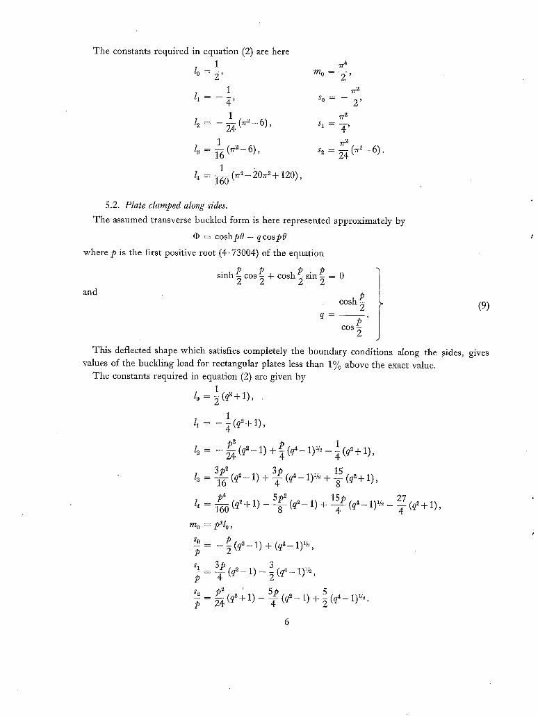
The preceding analysis has been computed for plates with opposite pairs of edges either simply- supported or clamped. Expressions are given in Sections 5.1 and 5.2 for the constants required in equation (2) under these conditions and a list of the results plotted is given in Section 5.3.
5.1. Plate Simply-Supported along Sides.
The assumed transverse buckled form, which is here given by
= cosTr0,
does not completely satisfy the conditio n of simple support along the sides of the plate. It is shown in Appendix II however that the total work done on the plate by the spurious moments introduced along the sides is zero. The analysis given in Appendix I thus remains valid.
The constants required in equation (2) are here 1
10=~,
1 4 ' 1
12 - 24 (~'~ - 6) ,
l~ = 1 (~.2_ 6) ,
1 /4 = 1-~ ( ~ - 2 0 ~ + 120),
7r 4
m 0 = ~-,
T-2
S 0 : 2 ~
7r 2 S 1 = -~-~
71-2 s~ = ~ (rr 2 - 6).
5.2. Plate clamped along sides.
The assumed transverse buckled form is here represented approximately by
= cosh/>0 - qcospO
where/> is the first positive root (4. 73004) of the equation
sinh~ cos p + coshP sin p = 0
and cosh/>
q m I
COS
This deflected shape which satisfies completely the boundary conditions along the sides, values of the buckling load for rectangular plates less than 1% above the exact value.
The constants required in equation (2) are given by 1 (q~+ 1),
l o=~
1 /1 = - ~ (q~ + 1),
/>~ p 1 l~ = - 2-~(q2-1) + (q4-1)1/~- g (q~+l ) ,
/>4 l~ ] 6 0 (q~+ 1) - 5/>2 15p 27
= - 8 - (q2- 1) + T (q~- 1)~/~ - (q2+ 1) T mo = / > % ,
So _ /> ( q ~ - 1) + (q~ - 1)1/2, /> 2
s I 3p 3 p - 4 ( q 2 _ l ) _ ~ ( q 4 1)1t2,
s~_ p~ ' ~ 5 p 24 (q~+ 1) - (qS_ 1) + ~ (q~- 1),~.
(9)
gives

5.3. Results.
The variation of the buckling coefficient exl with a/b 1 is plotted for a series of values of bz/bt and Nx2/Nxl in the figures listed below with various combinations of the boundary conditions. The corresponding curves for rectangular plates, which are also given in these figures, have been obtained where possible from R.Ae.S. data sheets; other cases have been calculated by a method similar to that given in this report.
(a) Buckling coefficient of plate with no normal load along sides.
End boundary conditions
simply-supported 7,
clamped
simply-supported
clamped
Side boundary conditions
simply-supported
~J
clamped
Nx2
0.8 1 1.2 0.8 1 1.2 0.8 1 1.2 0.8 1 1.2
Fig.
2 3 4 5 6 7 8 9
10 11 12 13
(b) Buckling coefficient of plate with no displacement of the sides normal to the direction of taper.
End boundary conditions
simply-supported clamped
simply-supported damped
Side boundary conditions
simply-supported
clamped l,
Nx2 Fig.
14 15 16 17
Specimen buckled shapes for the above loadings are shown in Figs. 18 and 19.
7

N O T A T I O N (See Fig. 1)
Suffices 1 and 2 on stress, middle-surface force and length symbols indicate values at x = 0
and x = a respectively.
a, b Length and width of plate
t Plate thickness
x, y Cartesian co-ordinates
! t x , y Local Cartesian co-ordinates on side
w Deflection
X, Y
bg p - 1
bl
x y = 1 + P a ' b ~
Y 0 -
X
gO W -
a
a /x - -
b l
= 1 + 0 . 5 p
Angle made by sides with x axis
E Young 's modulus
Poisson's ratio (taken as 0.3 in computat ions)
D Flexural rigidity = Et3/12(1 - v ~)
N x , Ny , N xy
O'x~ O'y~ 'Txy
O'x, O'y~ TXy
Middle-surface forces
Middle-surface stresses
E etc.
A
~F
0
f
~ 2 1 (;xl
Middle-surface force function such that N z - 3y~
Assumed transverse deflected shape
Funct ion of X
-- - - etc.
V 2
V 4
P, q
4, mi, si
Pi, qi, ri
ai
T
U
Mx,
T'
NOTATION--continued
Laplacian differential operator
Biharmonic differential operator
Defined by equations (9)
Coefficients defined by equations (1)
Coefficients defined by equations (4)
Coefficients defined by equations (3)
Coefficients defined by equations (5)
Work done by middle-surface forces
Strain energy
Moments referred to x, y axes
Moment about side
Work done on one side of plate by moment distribution Mx,.
No. Author(s)
1 G.G. Pope . . . .
2 L.V. Kantorovich and V. I. Kryloy
3 B. Klein . . . .
4 B. Klein . . . . . . . .
5 S.P. Timoshenko and S. Woinowsky-Krieger . . . .
REFERENCES
Title, etc.
The buckling of plates tapered in thickness. A.R.C.R. & M. 3309. October, 1961.
Approximate methods of higher analysis. Chapter 4. English translation of 3rd Russian edition by
C. D. Benster. Noordhoff. 1958.
Buckling of plates tapered in planform. J. App. Mech. (Trans. ASME). Vol. 78. June, 1956.
The buckling of tapered plates in compression. Aircraft Engineerh,g. December, 1956.
Theory of plates and shells. Chapters 4 and 10. 2nd edition, McGraw-Hill. 1959.

APPENDIX I
Basic Analysis of the Buckling of an Isosceles Trapezoidal Plate of Constant Thickness
In classical small-deflection theory s, the strain energy of bending of a plate is given by
u = ~- (V2w) ~ - 2 (1- , ) L~x2 ~y~ \ ~ @ / j dxdy.
The increment of the strain energy due to an infinitesimal arbitraryvariation 3w of the deflection
is thus
Lax ~ Oy 2 + ax ~ Oy 2, OxOy OxayJ dxdy.
Provided the variation 8w satisfies the boundary conditions of the plate and the flexural rigidity D is
constant, this expression can be integrated by parts twice to give
(10)
The work done on the plate by the middle-surface forces Nx,N u and N~ u is given by
ffl r - 2 N~ \Ox] + Ny \Oy] + 2Nxy dxdy. ~x ~y
Thus the increment of the work done due to the variation 8w is given by
ff{ ( } ~w ~ w ~w ~ w ~w ~ w __ ~ w ~ ~T = - Nx ~x ~x + N~ ~y ~y + Nx~ t ~x --~y + ~y Ox ] dxdy.
Provided both the deflection w and the variation 8w are zero along the edges of the plate and the middle-surface forces are in equilibrium, the increment 8 T of the work done can be integrated by parts to give
~ r = ~w Nx~-Zx~ + Nv-@y~ + 2Nxv oxoy/ dxdy, (11)
Equating expressions (10) and (11), we obtain
~w V4w- -~ N ~ + N v ~ + 2N~v oxoy]t
which may be rewritten in the non-dimensional form
~ + 2pzlz ~ OXzOy--~ ~ + tx ~ - - 1 2 ( 1 - v~)/x ~ + Y~ \
~ W ~ W ii + evl~ ~ ~ + 2~vpt, ~ ] d X d Y = 0 (12)
where x y
w = - W X = 1 + 0 - Y = - a a b I '
b2 a
bl 1, /z = ~ ,
e x - 12(1-v~)tz~D- % , ev = cry etc.
and b 1 and b 2 are the widths of the plate at x = 0 and x = a as shown in Fig. 1.
10

If W were the true deflected shape of the plate and the variation 3 W were completely arbitrary, this integral would yield the differential equation for the deformation of the plate. In the present analysis however W is represented approximately by the expression
W = f (X)cb(O) where
Y 0 = - -
X
and q) is an assumed function. The ordinary 'differential equation for f is found by considering a restricted variation 3 W such that
~ W = ~ f .
As the variation 3fis arbitrary, the integration sign with respect to X can be removed from expression (12), leaving
q) O 4 - - 12(1 v2)tz ~ %p" O~W d-x~2 ~ X x + 2pZlX2 0X~3 y2 + tz~ --~ y4 - - - ° ~ +
] I + evt, 2 ~ + 2vxvptz ~ ] d Y = 0. (13)
Now the most general system of middle-surface forces considered here is
= rio + lx,
~u = ~Y,
where the coefficients ai, fi~ and 7 are constants. Substituting for W in terms o f f and (I) in equation (13) and integrating with respect to Y, the
following differential equation is obtained for f.
P~_X~f ' ' + PaXaf '' + (P2 + q2 X2 + r2X3)X~f " + (Pl + q~ X2 + r ~ X S ) X f ' +
+ ( p o + q o X 2 + r o X a ) f = 0 (2')
where the coefficients are defined by equations (3) and (4). The arbitrary constants in the solution of equation (2') are found from the boundary conditions
at the ends of the plate. When the ends are clamped these conditions are satisfied completely; when the ends are simply-supported however the condition of zero moment cannot be satisfied exactly, hut is represented approximately by the expression
2 Zof" - X . l f' = o
which satisfies the requirement that the variation 3f should do no work on the boundary.
11

APPENDIX II
Plates with Simply-Supported Sides
In this report the buckled form of plates simply-supported along the sides has been expressed in the form
W = f ~
where the function (I~ satisfies the boundary conditions
dq~ [flP]0=±~/2 = [~"]0=±~/2 = 0, where q ) ' = ~ etc.
The bending-moment distribution Mx, about the sides of the plate which would strictly be necessary for the plate to assume this buckled form is given by
1 = - - [M~ + My]0=±~. 04) Mx, 1 + ,
Now the bending moments M x and M u are given by
+ v/z ~ ~-ff] My = a /z2 (iS)
where the derivatives of W can be expressed as
~2W 1 O~W 1 - - - , - 0 ' 7 . ( 1 6 ) OX 2 Xz [qJX~f " 20qYXf' + O( OO" +2*') f] O Y ~ X 2
Substituting equations (15) and (16) in equation (14), we obtain
p~D(P' M ~ , - aX 2 ( X f ' - f ) . (17)
Now the slope of the plate normal to the side 0 = $ is given by
F ~ , ] = ~W ~ W . L~y d0=~/~ t~ ~ cos ~7 + P ~ sin ~7
Osin ~fO ' = ~ c o s ~ - ~ ~ } ~ . (18)
Hence from equations (17) and (18) the total work done on the side 0 = ½ by the moment Mx,
,, _
is given by P2DO'2 (
2a I~
P2Dq)'~ ( 4a
P sin ( X f ' - f ) d X cos,) - ~ "~ .Jl
Psin )[/"] cos ~ - )_. ~ L 2 ~ j 1 .
Now the deflection at the ends of the plates considered in this report is zero, hence
T' = O.
Similarly integrating M x, along the side 0 = ½, it can be shown that the moments along each side are self-equilibrating.
12

,5
l N=..,
{1,
Fie. 1. Axes and notation.
ILl - 1

1,3.
I 0
0 - 4 o . 6 0 " 8 I ' 0
o. 3 +
Fla. 2. Buckling-stress diagram. Sides and ends simply-supported. No stress normal to sides.
I 0
B
4-
0 0
FIG. 3.
0 . 4 0 '6 0 '8 I ' 0
0.
Buckling-stress diagram. Sides and ends simply-supported. No stress normal to sides.
¢,
Nx21Nx, = 0 - 8 . N J N ~ , = 1.

I0
6
.-- ¢rml
4-
0"4- ~ 0 ' 8 " - - - " ~ " ' - - " 0 ' 8
I ' 0
0
0 I ~ 3 4 o.
Fro. 4. Buckling-stress diagram. Sides and ends simply-supported. No stress normal to sides.
N ~ / N ~ = 1.2.
14
12
I0
8
- - C I ' ~ 1
4
O 0
/
i \ \ 2. 3 4 cL
G
FIG. 5. Buckling-stress diagram. Sides simply- supported. Ends clamped. No stress normal to sides.
tV.2 /N~I = 0 . 8 .
0 : 4 -
O. 6 ~ z
O . e, .6. I I , O

14
Io
8
6
2 B 4 0.
FIG, 6, Buckling-stress diagram. Sides s imply- supported, Ends clamped, No stress normal to sides.
Nx2/Nxl = 1.0.
0.6 - ~
o'a ~ 1,0
12
I O
8
- ~ : n 6
4-
2
0 0
\ \
t' o.~ ~-~
~ ' - - ' ~ - - - o . B
I - 0
2. 5 .... el .
FIO. 7. Buckling-stress diagram. Sides s imply- supported. Ends clamped. No stress normal to sides.
N J N ~ = 1.2 .

14
IO
8
-o-m,
a.o
/
4
0 0 ~ 3
O.
Fro. 8. Buckling-stress diagram. Sides clamped. Ends simply-supported. No stress normal to sides.
N ~ / N~I = O" 8.
o . 4 O. 6 ~r~
I . 0 ~rl
14
I0
8
-o '~ l
6
4
o 0
0 - 4
2 3 4- O.
FIG. 9. Buckl ing-stress diagram. Sides clamped. Ends s imply-supported. No stress normal to sides.
Nx~/N~ 1 = 1 . 0 .
). 6 .~. ) - 8 _ _ • 0 ~r,

1 4
4-
A . /
o,
FIG. 10. Buckling-stress diagram. Sides clamped. Ends simply-supported. No stress normal to sides.
Nx2/Nxl = 1 . 2 .
0 - 4 - O ' G 0 ° 8
I 'O
18

- - l O ' : c !
2O
18
16
I,l-
I 0
4-
0 0
0 " 6
3 4 Q.
~r
FIG, 11, Buckling-stress diagram, Sides and ends clamped. No stress normal to sides.
N x z / N x l = O" 8.
19

m
- O ' ~ l
~ 0
[8
16
14
I0
8
t
£
0
0 • 2 3
G~
FIG. i2. Buckling-stress diagram. Sides and ends clamped. No stress normal to sides.
N J N ~ I = 1 .0 .
0"4
0.6
0-8
I'0
81
20

18
16
14-
12.
I o
4-
2.
0 . 6 ~2
0 " 8
I ' 0
O 1 2 8
Flo. 13. Budding-stress diagram. Sides and ends damped. No stress normal to sides.
N~I%~ = 1.2.
21

t,o
8
0
0 2 3 4 8 .
FIG. 14. Buckling-stress diagram. Sides and ends simply-supported. No strain normal to axis of taper.
gJNxl = 1 - 0 .
I O
5
4
2
o 0
t
".4,.,
2 CL
FIG. 15. Buckling-stress diagram. Sides simply- supported. Ends clamped. No strain normal to axis
of taper. N x . . / N x l = 1"0.
0 . 4 0 -5 0 - 8 ~r2 1 - 0 ~l
4-

k~ t . . ,o
14
Io
4
o
Fro. 16.
% 4 (l
g 5
Buckling-stress diagram. Sides clamped. Ends s imply-supported. No strain normal to axis of
taper. Nx~/Nxl = 1.0.
0 , 4 o . 6 ~ o. 8 Z"~ 1.0
16
|4
14
IO
O 0
/ \
Fm. 17.
I
~ ~ 0.6 ,&.~_ 0.8 "~(
I-0
a.
Buckling-stress diagram. Sides and ehds • clamped. No strain normal to axis of t a p e r .
N~2/Nxl = 1 "0.

.,.1
i/1
I11
I--
u1 P,
:E
0
LIJ LIJ
g N D 6
6 I M P L Y - S U P P O R T E D
E N D 8
C L A M P E D
~ EN0~
6 1 M P £ Y - ~ U P P O R T E D
w
~ EN~a Z
C L A M P E D o z
b ~ I-LI E:
I.,- I.- o
..=,,,, x ~ t.t.I . ~
"=CO - J I - - el. V L . J
o ~
E N D S
, 5 I M P L Y - S U P P O R T E D
END,.5
C L A M P , E O
0-=2 6" N~2 =I ~, ' T, = ° ' 4 ' N=,
l.iJ i~ ¢~la_
I.L.i.~. Do
=~_ ILl><
a-._l
O~ ~Z
END6
61M PLY-6UPPORTF.D
E N D 6
C L A M P E D
--=2 --O'4 ~ = I
FIe. 18. Specimen buckled shapes, sides simply-supported. FIG. 19. Specimen buckled shapes, sides clamped.

Publications of the Aeronautical Research Council
A N N U A L T E C H N I C A L R E P O R T S O F T H E A E R O N A U T I C A L
R E S E A R C H C O U N C I L ( B O U N D V O L U M E S )
I942 Vol. I. Aero and Hydrodynamics, Aerofoils, Airscrews, Engines. 75s. (post 2s. 9d.) Vol. II. Noise, Parachutes, Stability and Control, Structures, Vibration, Wind Tunnels. 47 s. 6d. (post 2s. 3d.)
x943 Vol. I. Aerodynamics, Aerofoils, Airscrews. 8os. (post 2s. 6d.) Vol. II. Engines, Flutter, Materials, Parachutes, Performance, Stability and Control, Structures.
9os. (post 2s. 9d.) 2944 Vol. I. Aero and Hydrodynamics, Aerofoils, Aircraft, Airscrews, Controls. 84 s. (post 3s.)
Vol. II. Flutter and Vibration, Materials, Miscellaneous, Navigation, Parachutes, Performance, Plates and Panels, Stability, Structures, Test Equipment, Wind Tunnels. 84s. (post 3s.)
t945 Vol. I. Aero and Hydrodynamics, Aerofoils. I3os. (post 3 s. 6d.) Vol. II. Aircraft, Airscrews, Controls. i3os. (post 3s. 6d.) Vol. I IL Flutter and Vibration, Instruments, Miscellaneous, Parachutes, Plates and Panels, Propulsion.
z3os. (post 3s. 3d.) Vol. IV. Stability, Structures, Wind Tunnels, Wind Tunnel Technique. I3os. (post 3s. 3d.)
2946 Vol. I. Accidents, Aerodynamics, Aerofoils and Hydrofoils. i68s. (post 3s. 9d.) Vol. II. Airscrews, Cabin Cooling, Chemical Hazards, Controls, Flames, Flutter, Helicopters, Instruments and
Instrumentation, Interference, Jets, Miscellaneous, Parachutes. 268s. (post 3 s. 3d.) Vol. III. Performance, Propulsion, Seaplanes, Stability, Structures, Wind Tunnels. 168s. (post 3s. 6d.)
~947 Vol. I. Aerodynamics, Aerofoils, Aircraft. i68s. (post 3s. 9d.) Vol. II. Airscrews and Rotors, Controls, Fintter, Materials, Miscellaneous, Parachutes, Propulsion, Seaplanes,
Stability, Structures; Take-off and Landing. i68s. (post 3s. 9d.)
i948 Vol. L Aerodynamics, Aerofoils, Aircraft, Airscrews, Controls, Flutter and Vibration, Helicopters, Instruments, Propulsion, Seaplane, Stability, Structures, Wind Tunnels. I3os. (post 3s. 3d.)
Vol. II. Aerodynamics, Aerofoils, Aircraft, Airscrews, Controls, Flutter and Vibration, Helicopters, Instruments, Propulsion, Seaplane, Stability, Structures, Wind Tunnels. I zos. (post 3 s. 3d.)
Special Volumes Vol. I. Aero and Hydrodynamics, Aerofoils, Controls, Flutter, Kites, Parachutes, Performance, Propulsion,
Stability. i26s. (post 3s.) Vol. II. Aero and Hydrodynamics, Aerofoils, Airscrews, Controls, Flutter, Materials, Miscellaneous, Parachutes,
Propulsion, Stability, Structures. I47s. (post 3s.) Vol. III. Aero and Hydrodynamics, Aerofoils, Airscrews, Controls, Flutter, Kites, Miscellaneous, Parachutes,
Propulsion, Seaplanes, Stability, Structures, Test Equipment. I89s. (post 3s. 9d.)
Reviews of the Aeronautical Research Council I939-48 3 s. (post 6d.) I949-54 5s- (post 5d.)
Index to all Reports and Memoranda published in the Annual Technical Reports i9o9-i947 R. & M. 2600 (out of print)
Indexes to the Reports and Memoranda of the Aeronautical Research Council Between Nos. 2351-2449 Between Nos. 2451-2549 Between Nos. 2551-2649 Between Nos. 2651-2749 Between Nos. 2751-2849 Between Nos. 2851-2949 Between Nos. 2951-3o49 Between Nos. 3o5x-3149
R. & M. No. 2450 as. (post 3d.) R. & M. No. 2550 2s. 6d. (post 3d.) R. & M. No. 265o 2s. 6d. (post 3d.) R. & M. No. 275o 2s. 6d. (post 3d.) R. & M. No. 285o 2s. 6d. (post 3d.) R. & M. No. 295o 3s. (post 3d.) R . & M . No. 3o5o 3 s.6d. (post 3d.) R. & M. No. 315o 3s. 6d. (post 3d.)
HER MAJESTY'S STATIONERY OFFICE from the addresses overleaf
R. & M. No. 3324
© Crown copyright i963
Printed and published by HER MAJESTY'S STATIONERY OFFICE
To be purchased from York House, Kingsway, London w.c.2
423 Oxford Street, London w.x I3A Castle Street, Edinburgh 2
Io9 St. Mary Street, Cardiff 39 King Street, Manchester
5 ° Fairfax Street, Bristol I 35 Smallbrook, Ringway, Birmingham 5
80 Chichester Street, Belfast x or through any bookseller
Printed in England
Ro & Mo No. 3324
S.Oo Code No. 23-3324