Embed Size (px)
Citation preview
Journal of Computational Engineering and Physical Modeling 1-2 (2018) 59-69
CEPM is an open access journal under the CC BY license (http://creativecommons.org/licenses/BY/4.0/)
Contents lists available at CEPM
Journal of Computational Engineering and Physical Modeling
Journal homepage: http://www.jcepm.com/
Buckling of Tapered Columns with Polygon Cross-Section
M. I. Salama1*
1. Civil Engineering Dept., Faculty of Engineering, Kafrelsheikh University, Kafelshekh, Egypt
Corresponding author: [email protected]
http://dx.doi.org/10.22115/CEPM.2018.136082.1032
ARTICLE INFO
ABSTRACT
Article history:
Received: 16 March 2018
Revised: 22 June 2018
Accepted: 22 June 2018
This paper is concerned with the elastic stability of slender
tapered columns of regular polygon cross-section with
constant volume is presented. Various end conditions of the
tapered columns such as pinned ends, clamped -pinned ends
and clamped ends are considered in this paper. The analysis
is developed using finite element method for linear,
parabolic and sinusoidal tapers assuming firstly circular
cross-section. The polygon cross-sections other the circular
one are studied by investigating a direct relation between the
side number of the polygon cross-section and the critical
load parameter. The main parameter in this study is the
section ratio that defined as the ratio between the section
depths at the mid-span of the considered column to that at
the column ends. The obtained numerical results are
introduced in many curves to describe the relation between
the buckling load and the section ratio considering linear,
parabolic and sinusoidal tapers and various side number of
the polygon cross-section for each end conditions. The
obtained results of the buckling factor are simple with
satisfactory accuracy compared with results that obtained in
other theoretical studies.
Keywords:
Stability,
Tapered Columns,
Buckling loads,
Finite element,
Constant volume.
1. Introduction
Stability of columns is an important item in structural engineering so that the critical buckling
loads of columns and its behavior’s under different cases of loading and different cases of end
conditions have been studied and documented in many researches and texts such as Timoshenko
60 M. I. Salama/ Journal of Computational Engineering and Physical Modeling 1-2 (2018) 59-69
[1]. The main goals of the design are the safety and economic so that increasing of the critical
loads of specific span length columns without increasing the column volume, are important in
the viewpoint of optimal design. Also, for architecture proposes, tapered columns may be
required.
Many studies for columns with constant volume are carried out by Keller [2], Tadjbakhsh and
Kelller [3], Barnes [4] and Cox and Overton [5] to determine the critical load and the strongest
columns. Lee and Oh [6] developed Numerical methods to solve elastic and critical buckling
loads of simply supported tapered column with constant volume. Also, Lee, Oh and Li [7]
studied the stability of tapered columns with polygon cross-section considering the case of
clamped ends only. The differential equation governing the buckled shape of solid tapered
columns with polygon cross-section having a constant volume is derived by Lee, Karr and Kim
[8] that solved numerically.
In this paper, stability study of slender solid tapered columns having constant volume with
regular polygon cross-section is carried out using finite element method assuming linear,
parabolic and sinusoidal tapers and considering various end conditions. Also, the effect of the
number of sides of the cross-section in the critical load is introduced in a direct relation.
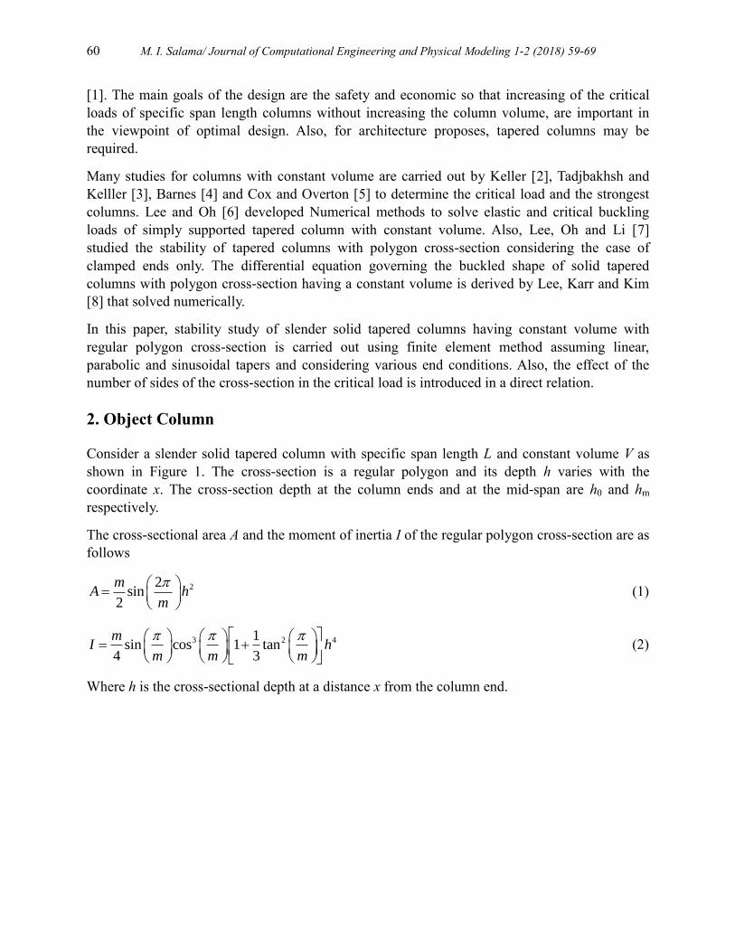
2. Object Column
Consider a slender solid tapered column with specific span length L and constant volume V as
shown in Figure 1. The cross-section is a regular polygon and its depth h varies with the
coordinate x. The cross-section depth at the column ends and at the mid-span are h0 and hm
respectively.
The cross-sectional area A and the moment of inertia I of the regular polygon cross-section are as
follows
22sin
2
mA h
m
(1)
3 2 41sin cos 1 tan
4 3
mI h
m m m
(2)
Where h is the cross-sectional depth at a distance x from the column end.
M. I. Salama/ Journal of Computational Engineering and Physical Modeling 1-2 (2018) 59-69 61
Fig. 1. Tapered column with regular polygon cross-section.
For linear taper, the variable depth h as a function of x is determined as follows
01 2 1x
h n hL
0 2x L (3-a)
01 2 1 2 1x
h n n hL
2L x L (3-b)
Where, the section ratio n is a non-dimensional parameter as follows
0
mhn
h (4)
Then, the volume V can be determined as follows
2
00
sin cos ,L
V Adx m Lhm m
21
13
n n (5)
Second, for parabolic taper, the cross-section depth h and volume V are obtained as follows
2
01 4 1 4 1x x
h n n hL L
(6)
2
00
sin cos ,L
V Adx m Lhm m
21
8 4 315
n n (7)
Finally, for the sinusoidal taper, the cross-section depth h and volume V are obtained as follows
01 1 sinx
h n hL
(8)
L/2
y yL
/2
h m
ho
h
x
L
xx
h
Cross Section

62 M. I. Salama/ Journal of Computational Engineering and Physical Modeling 1-2 (2018) 59-69
2
00
sin cos ,L
V Adx m Lhm m
21 41 1 1
2n n
(9)
Generally, Eqs (3, 6 and 8) can be written in the following form
0h h (10)
Where is a function of n and x
Then,
2
2sin cos
LV m h
m m
(11)
Substituting Eq. (11) in Eq. (2)
2 4
2 2
1 1cot tan
3 4
VI
m m m L
(12)
Assuming a column having a uniform circular cross-section with volume V .The moment of
inertia of its cross-sectional area Ie can be easily determined as follows
2
24e
VI
L (13)
Substituting Eq. (13) in Eq. (12)
4
2
1cot tan
3eI I
m m m
(14)
Thus, the critical buckling load for columns under study can be assumed as
2
2,e
cr
EIP
L
1 2. (15)
Where,
E is the modulus of elasticity of the column material,
is the buckling load parameter
represents the effect of the side number of the polygon section as cleared above. This factor
doesn't depend on the type of the taper (linear, parabolic, or sinusoidal) and can be expressed as
follows:
1
1cot tan
3m m m
(16)
M. I. Salama/ Journal of Computational Engineering and Physical Modeling 1-2 (2018) 59-69 63
But the factor represents the effect of taper type and the section ratio n that will be obtained
numerically by finite element method on the next section.
The factor can be determined as shown in Table 1
Table 1.
Effect of the side number of the polygon section m in buckling factor.
m 3 4 5 8 ∞
1.209 1.047 1.017 1.002 1.000
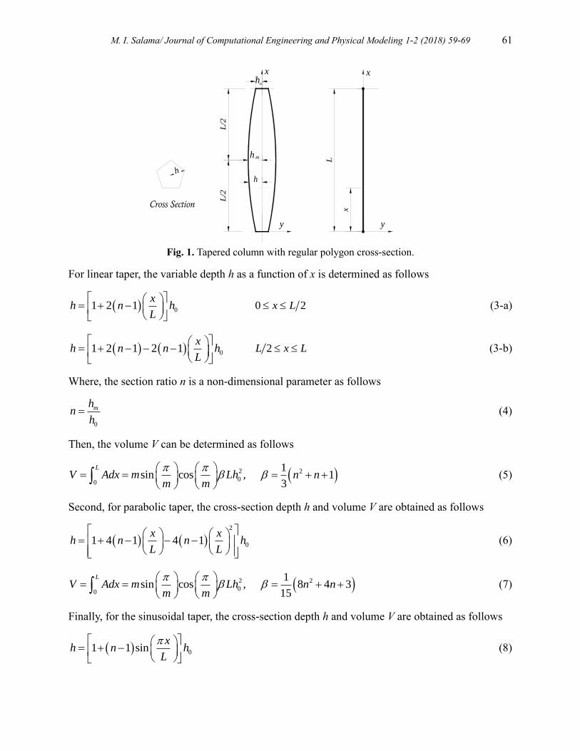
3. Method and assumptions
The column under study is modeled as a solid element as shown in Figure 2 with circular cross-
section (m = ∞) where the effect of the side number of the polygon section can be determined as
discussed by Eq. (16) and Table 1. The column length is divided by twenty segments and the
diameter of each segment cross-section is calculated by using Eqs (3, 6 and 8) for linear,
parabolic and sinusoidal tapered columns with different values of section ratio n. Different end
conditions such as pinned ends, clamped-pinned, ends and clamped ends are considered in the
models under study. The critical buckling loads for the column under study have been obtained
using SAP2000 program based on the finite element method.
n >1.0 n = 1.0 n < 1.0
Fig. 2. Finite element model of the Column under study.
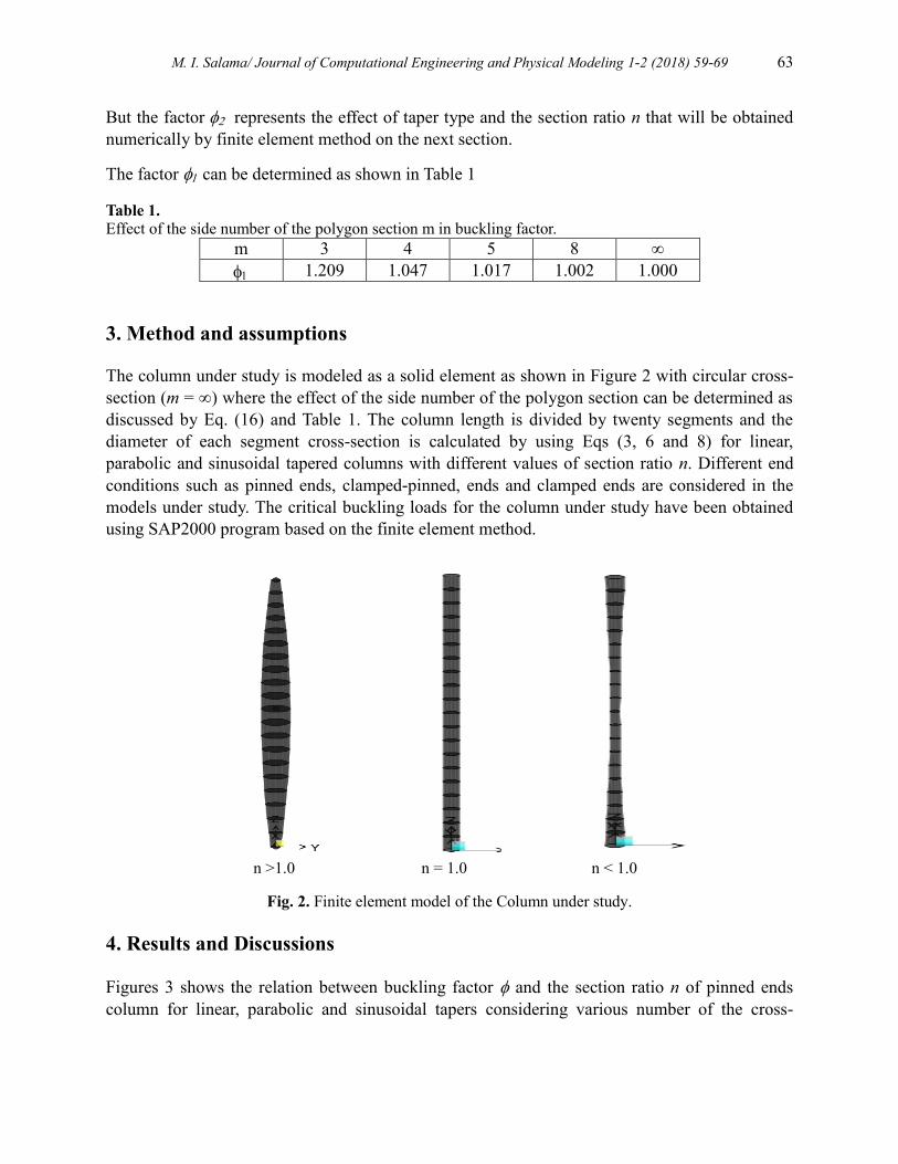
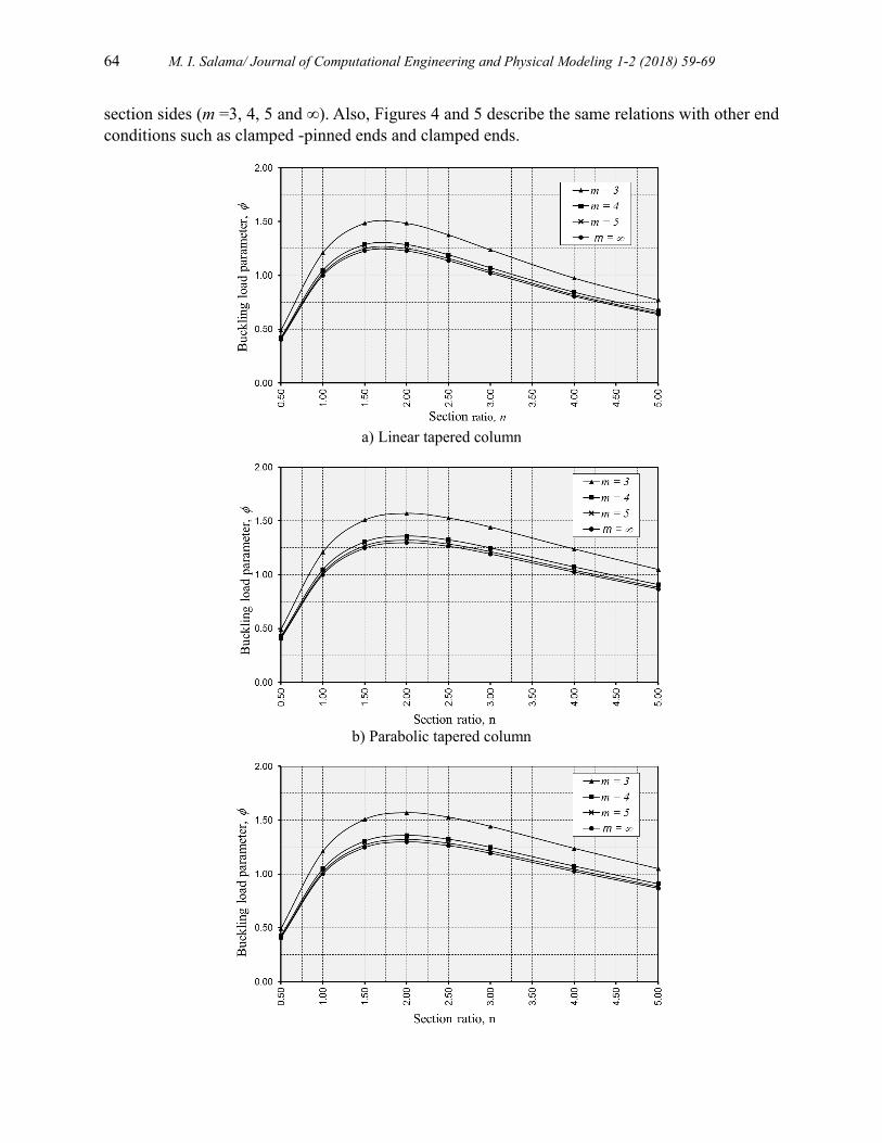
4. Results and Discussions
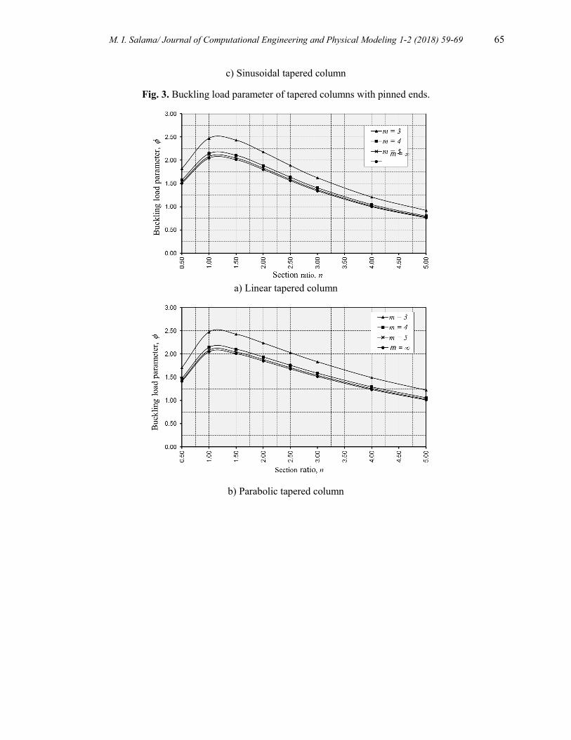
Figures 3 shows the relation between buckling factor and the section ratio n of pinned ends
column for linear, parabolic and sinusoidal tapers considering various number of the cross-
64 M. I. Salama/ Journal of Computational Engineering and Physical Modeling 1-2 (2018) 59-69
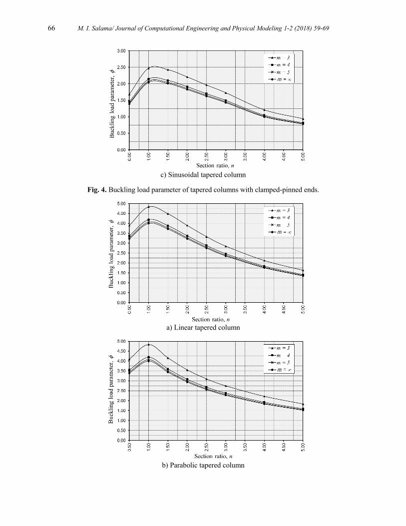
section sides (m =3, 4, 5 and ∞). Also, Figures 4 and 5 describe the same relations with other end
conditions such as clamped -pinned ends and clamped ends.
a) Linear tapered column
b) Parabolic tapered column
M. I. Salama/ Journal of Computational Engineering and Physical Modeling 1-2 (2018) 59-69 65
c) Sinusoidal tapered column
Fig. 3. Buckling load parameter of tapered columns with pinned ends.
a) Linear tapered column
b) Parabolic tapered column
66 M. I. Salama/ Journal of Computational Engineering and Physical Modeling 1-2 (2018) 59-69
c) Sinusoidal tapered column
Fig. 4. Buckling load parameter of tapered columns with clamped-pinned ends.
a) Linear tapered column
b) Parabolic tapered column
M. I. Salama/ Journal of Computational Engineering and Physical Modeling 1-2 (2018) 59-69 67
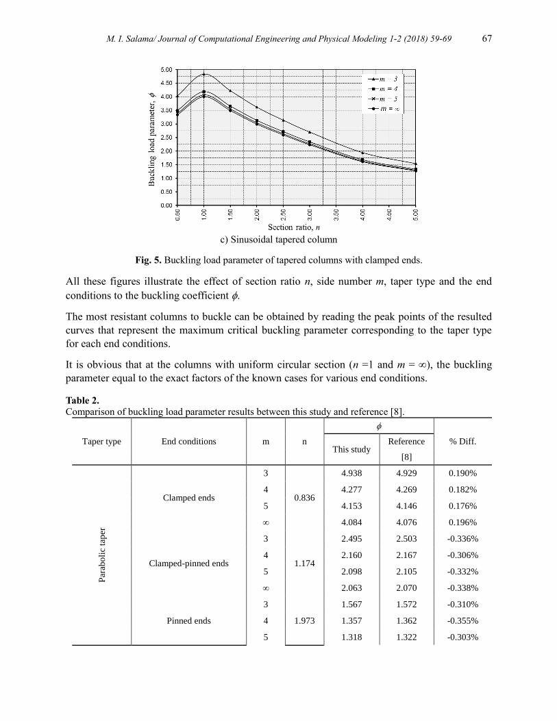
c) Sinusoidal tapered column
Fig. 5. Buckling load parameter of tapered columns with clamped ends.
All these figures illustrate the effect of section ratio n, side number m, taper type and the end
conditions to the buckling coefficient .
The most resistant columns to buckle can be obtained by reading the peak points of the resulted
curves that represent the maximum critical buckling parameter corresponding to the taper type
for each end conditions.
It is obvious that at the columns with uniform circular section (n =1 and m = ∞), the buckling
parameter equal to the exact factors of the known cases for various end conditions.
Table 2. Comparison of buckling load parameter results between this study and reference [8].
Taper type End conditions m n
% Diff. This study
Reference
[8]
Par
abo
lic
tap
er
Clamped ends
3
0.836
4.938 4.929 0.190%
4 4.277 4.269 0.182%
5 4.153 4.146 0.176%
∞ 4.084 4.076 0.196%
Clamped-pinned ends
3
1.174
2.495 2.503 -0.336%
4 2.160 2.167 -0.306%
5 2.098 2.105 -0.332%
∞ 2.063 2.070 -0.338%
Pinned ends
3
1.973
1.567 1.572 -0.310%
4 1.357 1.362 -0.355%
5 1.318 1.322 -0.303%
68 M. I. Salama/ Journal of Computational Engineering and Physical Modeling 1-2 (2018) 59-69
∞ 1.296 1.300 -0.308%
Sin
uso
idal
tap
er
Clamped ends
3
0.854
4.909 4.904 0.109%
4 4.252 4.247 0.109%
5 4.129 4.125 0.095%
∞ 4.060 4.056 0.099%
Clamped-pinned ends
3
1.183
2.499 2.507 -0.312%
4 2.164 2.171 -0.306%
5 2.102 2.108 -0.290%
∞ 2.067 2.073 -0.299%
Pinned ends
3
1.850
1.556 1.558 -0.113%
4 1.348 1.349 -0.093%
5 1.309 1.310 -0.088%
∞ 1.287 1.288 -0.078%
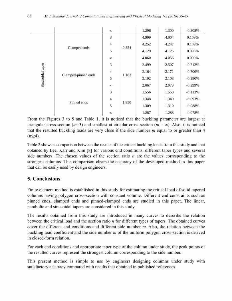
From the Figures 3 to 5 and Table 1, it is noticed that the buckling parameter are largest at
triangular cross-section (m=3) and smallest at circular cross-section (m = ∞). Also, it is noticed
that the resulted buckling loads are very close if the side number m equal to or greater than 4
(m≥4).
Table 2 shows a comparison between the results of the critical buckling loads from this study and that
obtained by Lee, Karr and Kim [8] for various end conditions, different taper types and several
side numbers. The chosen values of the section ratio n are the values corresponding to the
strongest columns. This comparison clears the accuracy of the developed method in this paper
that can be easily used by design engineers.
5. Conclusions
Finite element method is established in this study for estimating the critical load of solid tapered
columns having polygon cross-section with constant volume. Different end constraints such as
pinned ends, clamped ends and pinned-clamped ends are studied in this paper. The linear,
parabolic and sinusoidal tapers are considered in this study.
The results obtained from this study are introduced in many curves to describe the relation
between the critical load and the section ratio n for different types of tapers. The obtained curves
cover the different end conditions and different side number m. Also, the relation between the
buckling load coefficient and the side number m of the uniform polygon cross-section is derived
in closed-form relation.
For each end conditions and appropriate taper type of the column under study, the peak points of
the resulted curves represent the strongest column corresponding to the side number.
This present method is simple to use by engineers designing columns under study with
satisfactory accuracy compared with results that obtained in published references.
M. I. Salama/ Journal of Computational Engineering and Physical Modeling 1-2 (2018) 59-69 69
References
[1] Timoshenko, S. P., and Gere, J. M. (1983) “Theory of Elastic Stability”, McGraw-Hill Book
Company, London.
[2] Keller, J. B., (1960) “The shape of the strongest column”, Archive for Rational Mechanics and
Analysis, Vol. 5, pp. 275-285.
[3] Tadjbakhsh, I. and Keller, J. B., (1962) “Strongest columns and isoperimetric inequalities for
eigenvalues”, Journal of Applied Mechanics, ASME, Vol. 29, pp. 159-164.
[4] Barnes, D., C., (1988) “The shape of the strongest column is arbitrarily close to the shape of the
weakest column”, Quarterly of applied mathematics, Vol. 46, pp. 605-609.
[5] Cox, S., J. and Overton, M. I., (1992) “On the optimal design of columns against buckling”, SIAM
Journal of Mathematical analysis, Vol. 23, pp. 287-325.
[6] Lee, B. K. and Oh, S. J., (2000) “Elastica and buckling load of simple tapered column with
constant volume”, International Journal of solids and structures, Vol. 37, No. 18, pp. 2507-2518.
[7] Lee, B. K., Oh, S. J. and Li, G., (2002) “Buckling loads of columns of regular polygon cross-
section with constant volume and clamped ends”, Electronic Journal of structural engineering, Vol.
2, pp. 76-84.
[8] Lee, B. K., Carr, A. J. and Li, G., (2006) “Buckling loads of columns with constant volume”,
Journal of sound and vibration, Vol. 294, pp. 381-397.