Embed Size (px)
Citation preview

13. Buckling of ColumnsCHAPTER OBJECTIVES• Discuss the behavior of
columns.• Discuss the buckling of
columns.Determine the a ial load• Determine the axial loadneeded to buckle an idealcolumn.
• Analyze the buckling withbending of a column.
• Discuss methods used to design concentric andeccentric columns.
©2005 Pearson Education South Asia Pte Ltd 1

13. Buckling of ColumnsCHAPTER OUTLINE
1. Critical Load2. Ideal Column with Pin Supports2. Ideal Column with Pin Supports3. Columns Having Various Types of Supports
Design of Columns for Concentric Loading
©2005 Pearson Education South Asia Pte Ltd 2
Design of Columns for Eccentric Loading4.5.

13. Buckling of Columns13.1 CRITICAL LOAD
• Long slender members subjected to axialcompressive force are called columns.
• The lateral deflection that occurs iscalled buckling.
• The maximum axial load a column cansupport when it is on the verge ofbuckling is called the critical load, Pcr.
©2005 Pearson Education South Asia Pte Ltd 3

13. Buckling of Columns13.1 CRITICAL LOAD
• Spring develops restoring force F = k∆, whileapplied load P develops two horizontalcomponents, Px = P tan θ, which tends to push thepin further out of equilibrium.
• Since θ is small,∆ = θ(L/2) and tan θ ≈ θ.
• Thus, restoring springforce becomesF = kθL/2 andF = kθL/2, anddisturbing force is2P = 2Pθ.
©2005 Pearson Education South Asia Pte Ltd 4
2Px 2Pθ.

13. Buckling of Columns13.1 CRITICAL LOAD
• For kθL/2 > 2Pθ,
kL
• For kθL/2 < 2Pθ
mequilibriustable4
kLP <
• For kθL/2 < 2Pθ,
mequilibriuunstablekLP >
F kθL/2 2Pθ
mequilibriuunstable4
P >
• For kθL/2 = 2Pθ,
mequilibriuneutralkLPcr =
©2005 Pearson Education South Asia Pte Ltd 5
q4cr

13. Buckling of Columns13.2 IDEAL COLUMN WITH PIN SUPPORTS
• An ideal column is perfectly straight before loading,made of homogeneous material, and upon whichmade of homogeneous material, and upon whichthe load is applied through the centroid of the x-section.
• We also assume that the material behaves in alinear-elastic manner and the column buckles orbends in a single plane.
©2005 Pearson Education South Asia Pte Ltd 6

13. Buckling of Columns13.2 IDEAL COLUMN WITH PIN SUPPORTS
• In order to determine the critical load and buckledshape of column, we apply Eqn 12-10,
( )1-132
2M
dxdEI =υ
• Recall that this eqn assumethe slope of the elasticcurve is small andcurve is small anddeflections occur only inbending. We assume thatthe material behaves in alinear-elastic manner andthe column buckles or
©2005 Pearson Education South Asia Pte Ltd 7
the column buckles orbends in a single plane.

13. Buckling of Columns13.2 IDEAL COLUMN WITH PIN SUPPORTS
• Summing moments, M = −Pν, Eqn 13-1becomesbecomes
( )2-1302
2=⎟
⎠⎞
⎜⎝⎛+ υυ
EIP
dxd
• General solution is
( )313i ⎞⎜⎛⎞
⎜⎛ PCPC
• Since ν = 0 at x = 0 then C = 0
( )3-13cossin 21⎠⎞
⎜⎝⎛+
⎠⎞
⎜⎝⎛= x
EIPCx
EIPCυ
• Since ν = 0 at x = 0, then C2 = 0.Since ν = 0 at x = L, then
⎞⎛ P
©2005 Pearson Education South Asia Pte Ltd 8
0sin1 =⎟⎠⎞
⎜⎝⎛ L
EIPC

13. Buckling of Columns13.2 IDEAL COLUMN WITH PIN SUPPORTS
• Disregarding trivial soln for C1 = 0, we get⎞
⎜⎛ P
• Which is satisfied if
0sin =⎠⎞
⎜⎝⎛ L
EIP
Which is satisfied if
πnLEIP
=
• orEI
32122 EInP π ,...3,2,12 == n
LEInP π
©2005 Pearson Education South Asia Pte Ltd 9

13. Buckling of Columns13.2 IDEAL COLUMN WITH PIN SUPPORTS
• Smallest value of P is obtained for n = 1, so criticalload for column is 2EIP π
• This load is also referred to2L
Pcr =
as the Euler load. Thecorresponding buckledh i d fi d bshape is defined by
LxC πυ sin1=
• C1 represents maximumd fl ti hi h
L
©2005 Pearson Education South Asia Pte Ltd 10
deflection, νmax, which occursat midpoint of the column.

13. Buckling of Columns13.2 IDEAL COLUMN WITH PIN SUPPORTS
©2005 Pearson Education South Asia Pte Ltd 11

13. Buckling of Columns13.2 IDEAL COLUMN WITH PIN SUPPORTS
• A column will buckle about the principal axis of thex-section having the least moment of inertia(weakest axis).
• For example, the meter stick shown willb kl b t th i d tbuckle about the a-a axis and notthe b-b axis.Th i l t b d ll t• Thus, circular tubes made excellentcolumns, and square tube or thoseshapes having I ≈ I are selectedshapes having Ix ≈ Iy are selectedfor columns.
©2005 Pearson Education South Asia Pte Ltd 12

13. Buckling of Columns13.2 IDEAL COLUMN WITH PIN SUPPORTS
• Buckling eqn for a pin-supported long slendercolumn, 2column,
( )5-132
2
LEIPcr
π=
Pcr = critical or maximum axial load on column just before it begins to buckle. This load must not causebefore it begins to buckle. This load must not cause the stress in column to exceed proportional limit.
E = modulus of elasticity of materialyI = Least modulus of inertia for column’s x-sectional
area.
©2005 Pearson Education South Asia Pte Ltd 13
L = unsupported length of pinned-end columns.

13. Buckling of Columns13.2 IDEAL COLUMN WITH PIN SUPPORTS
• Expressing I = Ar2 where A is x-sectional area ofcolumn and r is the radius of gyration of x-sectionalarea.
( )( )6-132
2
rLE
crπσ =
σcr = critical stress, an average stress in column just before the column buckles. This stress is an elastic
( )
stress and therefore σcr≤ σY
E = modulus of elasticity of materialL = unsupported length of pinned-end columns.r = smallest radius of gyration of column, determined
√
©2005 Pearson Education South Asia Pte Ltd 14
from r = √(I/A), where I is least moment of inertia of column’s x-sectional area A.

13. Buckling of Columns13.2 IDEAL COLUMN WITH PIN SUPPORTS
• The geometric ratio L/r in Eqn 13-6 is known as theslenderness ratio.
• It is a measure of the column’s flexibility and will beused to classify columns as long, intermediate orshort.
©2005 Pearson Education South Asia Pte Ltd 15

13. Buckling of Columns13.2 IDEAL COLUMN WITH PIN SUPPORTS
IMPORTANT• Columns are long slender members that areg
subjected to axial loads.• Critical load is the maximum axial load that a
column can support when it is on the verge ofbuckling.
• This loading represents a case of neutralequilibrium.
©2005 Pearson Education South Asia Pte Ltd 16

13. Buckling of Columns13.2 IDEAL COLUMN WITH PIN SUPPORTS
IMPORTANT• An ideal column is initially perfectly straight, madey p y g
of homogeneous material, and the load is appliedthrough the centroid of the x-section.
• A pin-connected column will buckle about theprincipal axis of the x-section having the least
t f i t timoment of intertia.• The slenderness ratio L/r, where r is the smallest
radius of gyration of x section Buckling will occurradius of gyration of x-section. Buckling will occurabout the axis where this ratio gives the greatestvalue.
©2005 Pearson Education South Asia Pte Ltd 17
value.

13. Buckling of Columns13.2 IDEAL COLUMN WITH PIN SUPPORTS
©2005 Pearson Education South Asia Pte Ltd 18Smallest allowable slenderness ratio

13. Buckling of ColumnsEXAMPLE (6th Ed.)
A 7.2-m long A-36 steel tube having the x-section shown is to gbe used a pin-ended column. Determine the maximum
ll bl i l l d th lallowable axial load the column can support so that it does not bucklebuckle.
©2005 Pearson Education South Asia Pte Ltd 19
ππ 2EI=
L2PPcr

13. Buckling of ColumnsEXAMPLE (SOLN)
Use Eqn 13-5 to obtain critical load with Est = 200 GPa.st
2
2= π
LEIPcr 2L
kN2228= kN2.228=
©2005 Pearson Education South Asia Pte Ltd 20
13. Buckling of ColumnsEXAMPLE (SOLN)
This force creates an average compressive stress in the column of
( )( ) ( )[ ]mm7075
N/kN1000kN2.228222==
ππσ
APcr
cr ( ) ( )[ ]MPa100N/mm2.100
mm70752 ==
−ππA
Since σcr < σY = 250 MPa, application of Euler’s eqn is appropriate.pp p
©2005 Pearson Education South Asia Pte Ltd 21

13. Buckling of ColumnsEXAMPLE 13.1The A-36 steel W200×46 member shown is to be used as a pin-connected column. Determine the largest axial load it can support before it either begins to buckle
th t l i ldor the steel yields.
©2005 Pearson Education South Asia Pte Ltd 22
ππ 2EI=
L2PPcr

13. Buckling of ColumnsEXAMPLE 13.1 (SOLN)From table in Appendix B, column’s x-sectional area and moments of inertia are A = 5890 mm2, Ix = 45.5×106 mm4,and Iy = 15.3×106 mm4.By inspection, buckling will occur about the y-y axis.Applying Eqn 13-5, we have
2π EIP
( )[ ] ( )( )( )mm1000/m1mm10315kN/m10200 444262
2=π
LPcr
( )[ ] ( )( )( )( )m4
mm1000/m1mm103.15kN/m102002
44262=π
©2005 Pearson Education South Asia Pte Ltd 23
kN6.1887=

13. Buckling of ColumnsEXAMPLE 13.1 (SOLN)When fully loaded, average compressive stress in column is ( )N/kN1000kN6.1887Pcr ( )
2
2
N/5320
mm5890N/kN1000kN6.1887
==A
Pcrcrσ
Since this stress exceeds yield stress (250 N/mm2),
2N/mm5.320=
Since this stress exceeds yield stress (250 N/mm ), the load P is determined from simple compression:
N/250 2 P
kN51472mm5890
N/mm250 22
=
=
P
©2005 Pearson Education South Asia Pte Ltd 24
kN5.1472=P

13. Buckling of ColumnsCOLUMNS HAVING VARIOUS TYPES OF SUPPORTS
©2005 Pearson Education South Asia Pte Ltd 25

13. Buckling of Columns13.3 COLUMNS HAVING VARIOUS TYPES OF SUPPORTS
• Thus, smallest critical load occurs when n = 1, sothat 2EIπthat
• By comparing with Eqn 13-5 a column fixed-
( )9-134 2L
EIPcrπ
=
By comparing with Eqn 13 5, a column fixedsupported at its base will carry only one-fourth thecritical load applied to a pin-supported column.
©2005 Pearson Education South Asia Pte Ltd 26

13. Buckling of Columns13.3 COLUMNS HAVING VARIOUS TYPES OF SUPPORTS
Effective length• If a column is not supported by pinned-ends then• If a column is not supported by pinned-ends, then
Euler’s formula can also be used to determine thecritical load.
• “L” must then represent the distance between thezero-moment points.
• This distance is called the columns’ effective length,Le.
©2005 Pearson Education South Asia Pte Ltd 27

13. Buckling of Columns13.3 COLUMNS HAVING VARIOUS TYPES OF SUPPORTS
Effective length
©2005 Pearson Education South Asia Pte Ltd 28

13. Buckling of Columns13.3 COLUMNS HAVING VARIOUS TYPES OF SUPPORTS
Effective length• Many design codes provide column formulae that• Many design codes provide column formulae that
use a dimensionless coefficient K, known as theeffective-length factor.g
• Thus, Euler’s formula can be expressed as( )10-13KLLe =
Thus, Euler s formula can be expressed as
( )( )11-132
2EIPcrπ
=( )
( )
( )12132
2
E
KLcr
πσ =
©2005 Pearson Education South Asia Pte Ltd 29
( )( )12-132rKL
crσ =

13. Buckling of Columns13.3 COLUMNS HAVING VARIOUS TYPES OF SUPPORTS
Effective length• Here (KL/r) is the column’s effective-slenderness• Here (KL/r) is the column s effective-slenderness
ratio.
©2005 Pearson Education South Asia Pte Ltd 30

13. Buckling of ColumnsEXAMPLE 13.2A W150×24 steel column is 8 m long and is fixed at its ends as gshown. Its load-carrying capacity is increased by bracing it about th i i t t th tthe y-y axis using struts that are assumed to be pin-connected to its mid-height Determine theto its mid-height. Determine the load it can support so that the column does not buckle nor material exceed the yield stress. Take Est = 200 GPa and σY = 410 MPa.
©2005 Pearson Education South Asia Pte Ltd 31
st Y

13. Buckling of ColumnsEXAMPLE 13.2 (SOLN)Buckling behavior is different about the x and yyaxes due to bracing. Buckled shape for each case is shown. The effective length for buckling about the x-x axis is (KL)x = 0.5(8 m) = 4 m.F b kli b t thFor buckling about the y-yaxis, (KL)y = 0.7(8 m/2) = 2.8 m.W t I 13 4 106 4 d I 1 83 106 4
©2005 Pearson Education South Asia Pte Ltd 32
We get Ix = 13.4×106 mm4 and Iy = 1.83×106 mm4
from Appendix B.

13. Buckling of ColumnsEXAMPLE 13.2 (SOLN)Applying Eqn 13-11,
( ) ( )[ ] ( )m10413kN/m10200 462622 −EI ππ( )( )
( )[ ] ( )( )
( ) kN21653m4
m104.13kN/m1020022 ==
x
xxcr
PKL
EIP ππ
( )
( ) ( )[ ] ( )m1083.1kN/m10200
kN2.1653462622
=
−y
xcr
EIP
P
ππ( )
( )( )[ ] ( )
( )( ) kN8460
m8.2 22
=
==y
yycr
P
KLP
By comparison, buckling will occur about the y-yaxis
( ) kN8.460=ycrP
©2005 Pearson Education South Asia Pte Ltd 33
axis.

13. Buckling of ColumnsEXAMPLE 13.2 (SOLN)
Area of x-section is 3060 mm2, so average compressive stress in column will becompressive stress in column will be
( ) 22
3N/mm6.150
3060N108.460===
APcr
crσ
Since σ < σ = 410 MPa buckling will occur before
2m3060A
Since σcr < σY = 410 MPa, buckling will occur before the material yields.
©2005 Pearson Education South Asia Pte Ltd 34

13. Buckling of ColumnsEXAMPLE 13.2 (SOLN)
NOTE: From Eqn 13-11, we see that buckling always occur about the column axis having the largest slenderness ratio. Thus using data for the radius of gyration from table in Appendix B,
( ) 4.60mm2.66mm/m1000m4 ==⎟
⎠⎞
⎜⎝⎛
xrKL
( ) 3.114mm5.24
mm/m1000m8.2==⎟
⎠⎞
⎜⎝⎛
yrKL
Hence, y-y axis buckling will occur, which is the same conclusion reached by comparing Eqns 13-11 for
y
©2005 Pearson Education South Asia Pte Ltd 35
y p g qboth axes.

13. Buckling of ColumnsEXAMPLE 13.3 (SOLN)
©2005 Pearson Education South Asia Pte Ltd 36

13. Buckling of ColumnsEXAMPLE 13.3 (SOLN)
©2005 Pearson Education South Asia Pte Ltd 37

13. Buckling of Columns*13.6 DESIGN OF COLUMNS FOR CONCENTRIC LOADING
• To account for behavior of different-length columns,design codes specify several formulae that will bestg yfit the data within the short, intermediate, and longcolumn range.
Steel columns• Structural steel columns are designed on the basis
of formulae proposed by the Structural StabilityResearch Council (SSRC).F t f f t li d t th f l d• Factors of safety are applied to the formulae andadopted as specs for building construction by theAmerican Institute of Steel Construction (AISC)
©2005 Pearson Education South Asia Pte Ltd 38
American Institute of Steel Construction (AISC).

13. Buckling of Columns*13.6 DESIGN OF COLUMNS FOR CONCENTRIC LOADING
Steel columns• For long columns the Euler formula is used A• For long columns, the Euler formula is used. A
factor of safety F.S. = 23/12 ≈ 1.92 is applied. Thusfor design,g ,
( )( )21-13200
/2312
2
2≤≤⎟
⎠⎞
⎜⎝⎛=
rKL
rKL
rKLE
callow
πσ
• Value of slenderness ratio obtained by( )
2 2EKL π⎞⎛ ( )22-132Yc
Er
KLσπ
=⎟⎠⎞
⎜⎝⎛
©2005 Pearson Education South Asia Pte Ltd 39
13. Buckling of Columns*13.6 DESIGN OF COLUMNS FOR CONCENTRIC LOADING
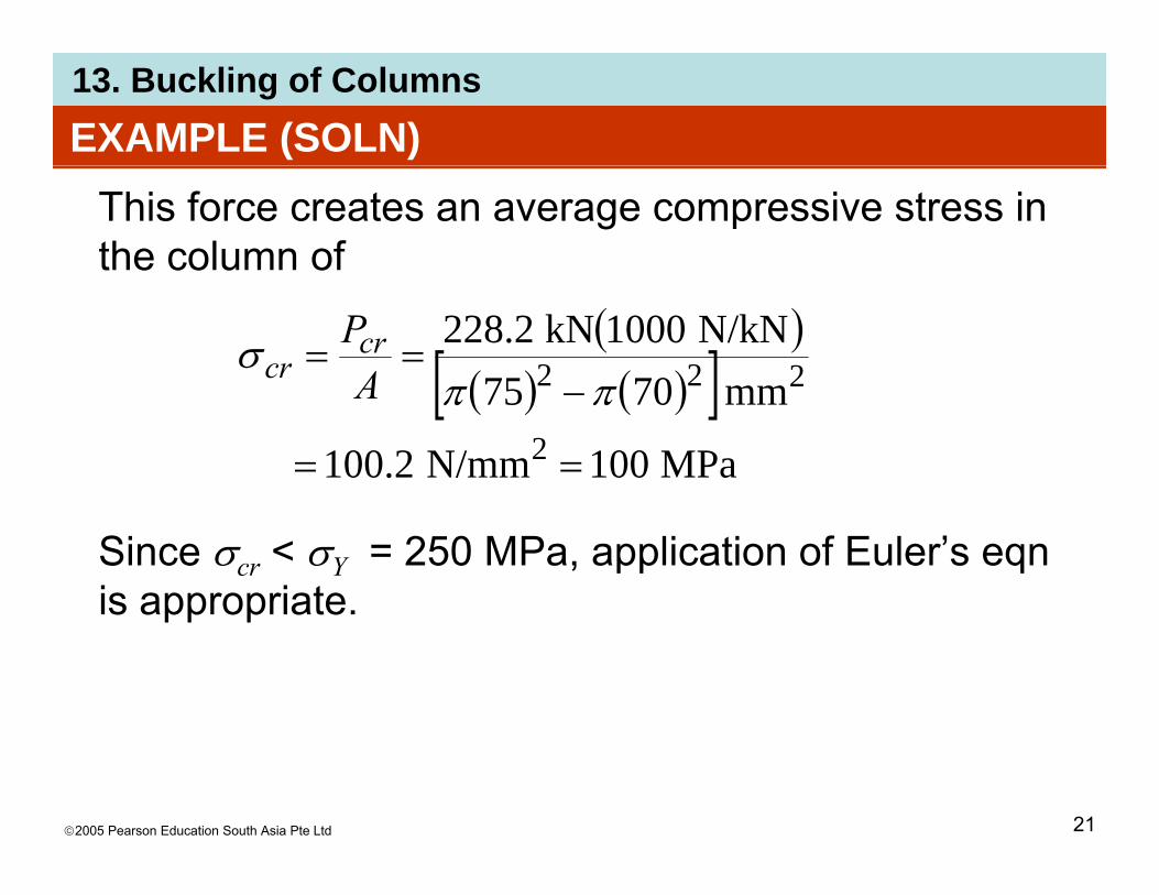
Steel columns• For slenderness ratio lesser than (KL/r) the design• For slenderness ratio lesser than (KL/r)c, the design
eqn is ( )( )
/1 2
2
⎥⎥⎤
⎢⎢⎡− Y
rKL σ( ) ( )23-13
3
/23
2
⎥⎤
⎢⎡ ⎞⎜⎛
⎥⎤
⎢⎡ ⎞
⎜⎛
⎥⎥⎦⎢
⎢⎣=
Yc
allowKLKL
rKLσ
}88
3
35{ 3
⎥⎥⎥⎥
⎢⎢⎢⎢
⎞⎜⎛
⎠⎜⎝−
⎥⎥⎥
⎢⎢⎢
⎞⎜⎛
⎠⎜⎝+⎟
⎠⎞
⎜⎝⎛
KLr
KLr
88 ⎥⎦
⎢⎣ ⎠
⎞⎜⎝⎛
⎥⎥⎦⎢
⎢⎣ ⎠⎜⎝ cc rr
©2005 Pearson Education South Asia Pte Ltd 40

13. Buckling of Columns*13.6 DESIGN OF COLUMNS FOR CONCENTRIC LOADING
Steel columns
©2005 Pearson Education South Asia Pte Ltd 41
13. Buckling of Columns*13.6 DESIGN OF COLUMNS FOR CONCENTRIC LOADING
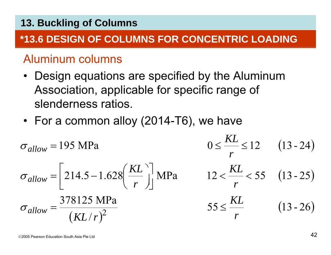
Aluminum columns• Design equations are specified by the AluminumDesign equations are specified by the Aluminum
Association, applicable for specific range ofslenderness ratios.
• For a common alloy (2014-T6), we have
( )2413120MP195 KL≤≤ ( )
( )25135512MPa62815214
24-13120MPa195
KLKLr
ll
allow
<<⎥⎤
⎢⎡ ⎞
⎜⎛=
≤≤=
σ
σ
( )
( )26-1355MPa378125
25-135512MPa628.15.214
KLrr
ll
allow
≤=
<<⎥⎦⎢⎣ ⎠⎜⎝
−=
σ
σ
©2005 Pearson Education South Asia Pte Ltd 42
( )( )26-1355
/ 2 rrKLallow ≤=σ

13. Buckling of Columns*13.6 DESIGN OF COLUMNS FOR CONCENTRIC LOADING
Aluminum columns
©2005 Pearson Education South Asia Pte Ltd 43

13. Buckling of Columns*13.6 DESIGN OF COLUMNS FOR CONCENTRIC LOADING
Timber columns• Timber design formulae published by the National• Timber design formulae published by the National
Forest Products Association (NFPA) or AmericanInstitute of Timber Construction (AITC).( )
©2005 Pearson Education South Asia Pte Ltd 44

13. Buckling of Columns*13.6 DESIGN OF COLUMNS FOR CONCENTRIC LOADING
Timber columns• NFPA’s formulae for short, intermediate and longNFPA s formulae for short, intermediate and long
columns having a rectangular x-section ofdimensions b and d (smallest dimension),
( )27-13110MPa25.8 ≤≤=d
KLallowσ
( )28-132611MPa026/
31125.8
2≤<
⎥⎥⎦
⎤
⎢⎢⎣
⎡⎟⎠⎞
⎜⎝⎛−=
dKLdKL
d
allowσ
( )( )29-135026MPa3718
0.263
2 ≤<=
⎥⎦⎢⎣ ⎠⎝
dKL
d
allowσ
©2005 Pearson Education South Asia Pte Ltd 45
( )( )
/ 2 ddKLallow

13. Buckling of Columns*13.6 DESIGN OF COLUMNS FOR CONCENTRIC LOADING
Procedure for analysisColumn analysisColumn analysis• When using any formula to analyze a column, or to
find its allowable load, it is necessary to calculate, ythe slenderness ratio in order to determine whichcolumn formula applies.
• Once the average allowable stress has beencomputed, the allowable load in the column isd t i d f P Adetermined from P = σallowA.
©2005 Pearson Education South Asia Pte Ltd 46

13. Buckling of Columns*13.6 DESIGN OF COLUMNS FOR CONCENTRIC LOADING
Procedure for analysisColumn designColumn design• If a formula is used to design a column, or to
determine the column’s x-sectional area for a givengloading and effective length, then a trial-and-checkprocedure generally must be followed if the columnhas a composite shape, such as a wide-flangesection.O i t th l ’ ti l• One way is to assume the column’s x-sectional
©2005 Pearson Education South Asia Pte Ltd 47
area A', and calculate the corresponding stressσ'= P/A'.

13. Buckling of Columns*13.6 DESIGN OF COLUMNS FOR CONCENTRIC LOADING
Procedure for analysisColumn designColumn design• Also, with A' use an appropriate design formula to
determine the allowable stress allow.• From this, calculate the required column area
Areq’d = P/σallow.req d allow
• If A' > Areq’d, the design is safe. When makingcomparison, it is practical to require A' to be close tobut greater than Areq’d, usually within 2-3%. Aredesign is necessary if A' < Areq’d.
©2005 Pearson Education South Asia Pte Ltd 48

13. Buckling of Columns*13.6 DESIGN OF COLUMNS FOR CONCENTRIC LOADING
Procedure for analysisColumn designColumn design• Whenever a trial-and-check procedure is repeated,
the choice of an area is determined by theypreviously calculated required area.
• In engineering practice, this method for design isg g p gusually shortened through the use of computersoftware or published tables and graphs.
©2005 Pearson Education South Asia Pte Ltd 49

13. Buckling of Columns*13.6 DESIGN OF COLUMNS FOR CONCENTRIC LOADING
Procedure for analysisColumn designColumn design
©2005 Pearson Education South Asia Pte Ltd 50
• The flowchart summarizes the analysis procedure
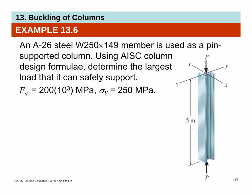
13. Buckling of ColumnsEXAMPLE 13.6An A-26 steel W250×149 member is used as a pin-supported column. Using AISC column gdesign formulae, determine the largest load that it can safely support. Est = 200(103) MPa, σY = 250 MPa.
©2005 Pearson Education South Asia Pte Ltd 51

13. Buckling of ColumnsEXAMPLE 13.6 (SOLN)
From Appendix B,A = 19000 mm2; r = 117 mm; r = 67 4 mmA = 19000 mm ; rx = 117 mm; ry= 67.4 mm.Since K = 1 for both x and y axes buckling, slenderness ratio is largest if r is used Thusslenderness ratio is largest if ry is used. Thus
( )( )( )
18.74mm467
mm/m1000m51 ==r
KL
From Eqn 13-22, ( )mm4.67r
2 2=⎞
⎜⎛ π EKL
( )( )MPa102002 32
=⎠
⎜⎝
π
σYcr
©2005 Pearson Education South Asia Pte Ltd 52
( )( ) 66.125MPa250
MPa102002==
π

13. Buckling of ColumnsEXAMPLE 13.6 (SOLN)Here 0 < KL/r < (KL/r)c, so Eqn 13-23 applies
( )1874 2 ⎤⎡ ( )( )( ) ( )1874187435
MPa25066.1252
18.741
3
2
⎤⎡⎤⎡⎞⎛
⎥⎦
⎤⎢⎣
⎡−
=allowσ( )( )
( )( )66.1258
18.7466.125818.743
35
3
3⎥⎦
⎤⎢⎣
⎡−⎥⎦
⎤⎢⎣⎡+⎟
⎠⎞
⎜⎝⎛
Allowable load P on column is
MPa85.110=
Allowable load P on column is
mm19000N/mm85.110; 2
2 == PA
Pallowσ
©2005 Pearson Education South Asia Pte Ltd 53
kN2106N2106150 ==P

13. Buckling of Columns
©2005 Pearson Education South Asia Pte Ltd 54

13. Buckling of Columns
©2005 Pearson Education South Asia Pte Ltd 55

13. Buckling of ColumnsEXAMPLE 13.8A bar having a length of 750 mm is used to support an axial compressive load of 60 kN. It is pin-supported at its ends and made f 2014 T6 l i llfrom a 2014-T6 aluminum alloy.Determine the dimensions of its x-sectional area if its width is to bex-sectional area if its width is to be twice its thickness.
©2005 Pearson Education South Asia Pte Ltd 56

13. Buckling of ColumnsEXAMPLE 13.8 (SOLN)
Since KL = 750 mm is the same for x-x and y-y axes buckling, largest slenderness ratio is determinedbuckling, largest slenderness ratio is determined using smallest radius of gyration, using Imin = Iy:
( ) 125987501KLKL ( )( ) ( ) ( )[ ]
( )11.25982/212/1
7501/ 3 bbbbbAI
KLrKL
yy===
Since we do not know the slenderness ratio, we apply Eqn 13-24 first,q ,
( )( )
N/mm1952
N1060;N/mm195 23
2 ==bbA
P
©2005 Pearson Education South Asia Pte Ltd 57
( )mm40.12=b
13. Buckling of ColumnsEXAMPLE 13.8 (SOLN)
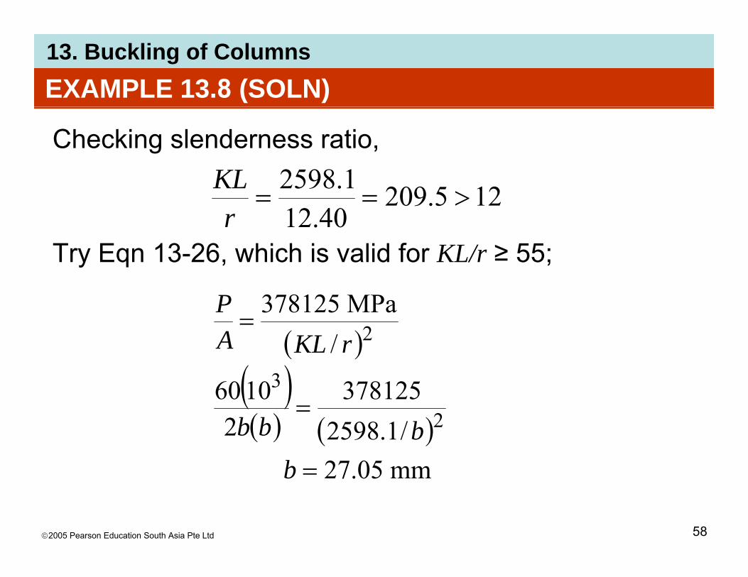
Checking slenderness ratio, 12598KL
Try Eqn 13 26 which is valid for KL/r ≥ 55;
125.20940.12
1.2598>==
rKL
Try Eqn 13-26, which is valid for KL/r ≥ 55;
MPa378125=
P( )
( ) 3781251060
/3
2rKLA
( )( ) ( )
mm0527/1.2598
3781252
10602
=
=
bbbb
©2005 Pearson Education South Asia Pte Ltd 58
mm05.27=b

13. Buckling of ColumnsEXAMPLE 13.8 (SOLN)
From Eqn (1),
O !00961.2598KL
Note: It would be satisfactory to choose the x section
OK!5500.9605.27
1.2598>==
rKL
Note: It would be satisfactory to choose the x-section with dimensions 27 mm by 54 mm.
©2005 Pearson Education South Asia Pte Ltd 59

13. Buckling of ColumnsEXAMPLE 13.9A board having x-sectional dimensions of 150 mm by 40 mm yis used to support an axial load of 20 kN. If the board is assumed to be pin-supported at its top and base, determine its greatest allo abledetermine its greatest allowable length L as specified by the NFPA.
©2005 Pearson Education South Asia Pte Ltd 60

13. Buckling of ColumnsEXAMPLE 13.9 (SOLN)By inspection, board will buckle about the y axis. In the NFPA eqns, d = 40 mm. Assuming that Eqn 13-29 applies, we have
MP3718P( )
( )/MPa3718
2=dKLA
P
( )( )( ) ( )mm40/1
N/mm3718mm40mm150
N10202
23=
L( )mm1336=L
©2005 Pearson Education South Asia Pte Ltd 61

13. Buckling of ColumnsEXAMPLE 13.9 (SOLN)
Here ( ) 4.33mm40
mm13361==
dKL
Since 26 < KL/d ≤ 50 the solution is valid
mm40d
Since 26 < KL/d ≤ 50, the solution is valid.
©2005 Pearson Education South Asia Pte Ltd 62

13. Buckling of Columns*13.7 DESIGN OF COLUMNS FOR ECCENTRIC LOADING
• A column may be required tosupport a load acting at its
d l b k tedge or on an angle bracketattached to its side.
• The bending moment M = Pe• The bending moment M = Pe,caused by eccentric loading,must be accounted for whencolumn is designed.
Use of available column formulaeSt di t ib ti ti ti l f• Stress distribution acting over x-sectional area ofcolumn shown is determined from both axial force Pand bending moment M = Pe.
©2005 Pearson Education South Asia Pte Ltd 63
and bending moment M Pe.

13. Buckling of Columns*13.7 DESIGN OF COLUMNS FOR ECCENTRIC LOADING
Use of available column formulae• Maximum compressive stress isMaximum compressive stress is
( )30-13max IMc
AP+=σ
• A typical stress profile is also shown here.• If we assume entire x-section is subjected to uniform• If we assume entire x-section is subjected to uniform
stress σmax, then we can compare it with σallow, whichis determined from formulae given in chapter 13.6.g p
• If σmax ≤ σallow, then column can carry the specifiedload.
©2005 Pearson Education South Asia Pte Ltd 64

13. Buckling of Columns*13.7 DESIGN OF COLUMNS FOR ECCENTRIC LOADING
Use of available column formulae• Otherwise, the column’s area A is increased and aOtherwise, the column s area A is increased and a
new σmax and σallow are calculated.• This method of design is rather simple to apply andg p pp y
works well for columns that are short or intermediatelength.
• Calculations of σallow is usually done using thelargest slenderness ratio for the column regardless
f th i b t th l i b diof the axis about the column experiences bending.
©2005 Pearson Education South Asia Pte Ltd 65

13. Buckling of Columns*13.7 DESIGN OF COLUMNS FOR ECCENTRIC LOADING
Interaction formula• It is sometimes desirable to see how the bendingIt is sometimes desirable to see how the bending
and axial loads interact when designing aneccentrically loaded column.
• We will consider the separate contributions made tothe total column area from the axial force and themoment.
• If allowable stress for axial load is (σa)allow, theni d f th l d d t t threquired area for the column needed to support the
load P isPA =
©2005 Pearson Education South Asia Pte Ltd 66
( )allowaaA
σ=

13. Buckling of Columns*13.7 DESIGN OF COLUMNS FOR ECCENTRIC LOADING
Interaction formula• Similarly, if allowable bending stress is (σb)allow, thenSimilarly, if allowable bending stress is (σb)allow, then
since I = Ar2, required area of column needed toresist eccentric moment is determined from flexureformula,
( ) 2r
McA
allowbb σ=
©2005 Pearson Education South Asia Pte Ltd 67

13. Buckling of Columns*13.7 DESIGN OF COLUMNS FOR ECCENTRIC LOADING
Interaction formula• Thus, total area A for the column needed to resistThus, total area A for the column needed to resist
both axial force and bending moment requires that
( ) ( )2
2 ≤+=+allowballowa
ba Ar
McPAAσσ
( ) ( )
( )
1// 2
≤+allowballowa
ArMcAPor
σσσσ
( ) ( ) ( )31-131≤+allowb
b
allowa
a
σσ
σσ
©2005 Pearson Education South Asia Pte Ltd 68

13. Buckling of Columns*13.7 DESIGN OF COLUMNS FOR ECCENTRIC LOADING
Interaction formulaσa = axial stress caused by force P and determinedσa axial stress caused by force P and determined
from σa = P/A, where A is the x-sectional area of the column.
σb = bending stress caused by an eccentric load or applied moment M; σb is found from σb = Mc/I, where I is the moment of inertia of x-sectional area computed about the bending or neutral axis.
( ) ( ) 1
Mcallowb
b
allowa
a ≤+σσ
σσ
©2005 Pearson Education South Asia Pte Ltd 69
( ) ( ) ( )31-132 Ar
McP
allowballowa
≤+σσ
13. Buckling of Columns*13.7 DESIGN OF COLUMNS FOR ECCENTRIC LOADING
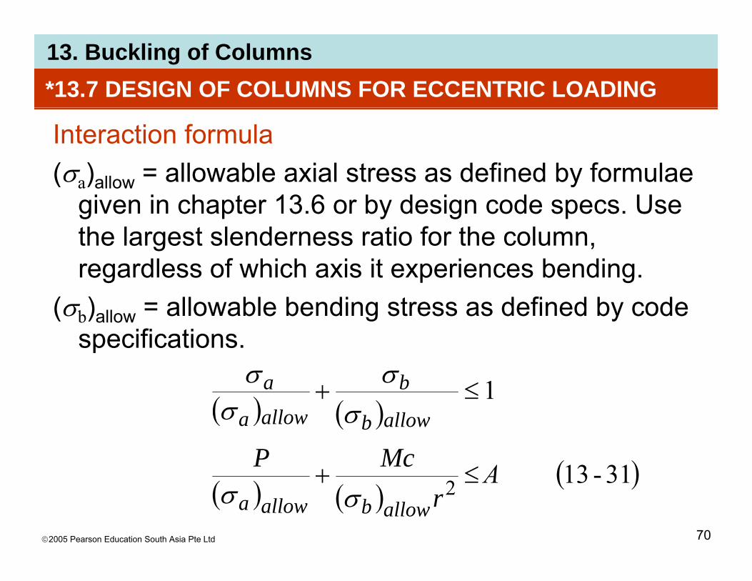
Interaction formula(σa)allow = allowable axial stress as defined by formulae(σa)allow allowable axial stress as defined by formulae
given in chapter 13.6 or by design code specs. Use the largest slenderness ratio for the column, regardless of which axis it experiences bending.
(σb)allow = allowable bending stress as defined by code specifications.
( ) ( )1≤+ ba σσ
( ) ( )
( )3113≤+McP
allow allowba σσ
©2005 Pearson Education South Asia Pte Ltd 70
( ) ( )( )31-13A2 ≤+
rallowballowa σσ

13. Buckling of Columns*13.7 DESIGN OF COLUMNS FOR ECCENTRIC LOADING
Interaction formula• Eqn 13-31 is sometimes referred to as theEqn 13 31 is sometimes referred to as the
interaction formula.• This approach requires a trial-and-check procedure.pp q p• Designer needs to choose an available column and
check to see if the inequality is satisfied.q y• If not, a larger section is picked and the process
repeated.• American Institute of Steel Construction specifies
the use of Eqn 13-31 only when the axial-stress ratio
©2005 Pearson Education South Asia Pte Ltd 71
σa/(σa)allow ≤ 0.15.

13. Buckling of ColumnsEXAMPLE 13.10Column is made of 2014-T6 aluminum alloy and is used to ysupport an eccentric load P. Determine the magnitude of P that
b t d if l i fi dcan be supported if column is fixed at its base and free at its top. Use Eqn 13-30Eqn 13-30.
©2005 Pearson Education South Asia Pte Ltd 72

13. Buckling of ColumnsEXAMPLE 13.10 (SOLN)
K = 2. Largest slenderness ratio for column is( )mm16002KL ( )
( )( )( )[ ] ( )( )[ ]1.277
mm80mm40/mm408012/1mm160023mm
==r
KL
By inspection, Eqn 13-26 must be used (277.1 > 55).MP378125MP378125
( ) ( )MPa92.4
1.277MPa378125MPa378125
22allow ===rKL
σ
©2005 Pearson Education South Asia Pte Ltd 73

13. Buckling of ColumnsEXAMPLE 13.10 (SOLN)
Actual maximum compressive stress in the column is determined from the combination of axial load anddetermined from the combination of axial load and bending. ( )
IcPe
AP
max +=σ
( )( )( )
( )( )( )PP
mm80mm4012/1mm40mm20
mm80mm40 3+=
Assuming that this stress is uniform over the x-
( ) ( )( )( )P00078125.0=
Assuming that this stress is uniform over the xsection, instead of just at the outer boundary,
00078125.092.4;maxallow == Pσσ
©2005 Pearson Education South Asia Pte Ltd 74
kN30.6N6.6297;maxallow
==P

13. Buckling of ColumnsEXAMPLE 13.11The A-36 steel W150×30 column is pin-connected at its ends and subjected to eccentric load P. Determine the maximum
ll bl l f P i thallowable value of P using the interaction method if allowable bending stress isbending stress is (σb)allow = 160 MPa, E = 200 GPa, and σY = 250 MPa.Y
©2005 Pearson Education South Asia Pte Ltd 75

13. Buckling of ColumnsEXAMPLE 13.11 (SOLN)
K = 1. The geometric properties for the W150×30 are taken from the table in Appendix B.taken from the table in Appendix B.
mm101.17mm3790 462 ×== IA x
We consider r as it lead to largest value of the
mm157mm2.38 == dry
We consider ry as it lead to largest value of the slenderness ratio. Ix is needed since bending occurs about the x axis (c = 157 mm/2 = 78.5 mm). To ( )determine the allowable bending compressive stress, we have ( )( ) 71104mm/m1000m41KL
©2005 Pearson Education South Asia Pte Ltd 76
( )( ) 71.104mm2.38
==r

13. Buckling of Columns
©2005 Pearson Education South Asia Pte Ltd 77
13. Buckling of ColumnsEXAMPLE 13.11 (SOLN)
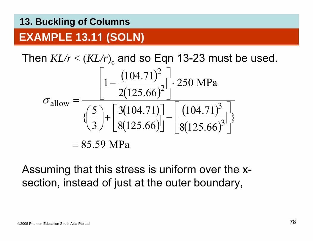
Then KL/r < (KL/r)c and so Eqn 13-23 must be used.( )71104 2 ⎤⎡ ( )( )( ) ( )
MPa25066.125271.1041
3
2
allow ⎤⎡⎤⎡⎞⎛
⋅⎥⎦
⎤⎢⎣
⎡−
=σ( )( )
( )( )
}66.125871.104
66.125871.1043
35{ 3
3allow
⎥⎦
⎤⎢⎣
⎡−⎥⎦
⎤⎢⎣⎡+⎟
⎠⎞
⎜⎝⎛
A i th t thi t i if th
MPa59.85=
Assuming that this stress is uniform over the x-section, instead of just at the outer boundary,
©2005 Pearson Education South Asia Pte Ltd 78

13. Buckling of ColumnsEXAMPLE 13.11 (SOLN)
Applying the interaction formula Eqn 13-31 yieldsbσσ
( ) ( )( )( ) ( ) mm10117/2/mm157mm750mm3790/
1
462
≤+
PPallowb
b
allowa
a
σσ
σσ
( )( ) ( )
kN6540
1N/mm160
mm101.17/2/mm157mm750N/mm59.85
mm3790/22
=
=+
P
PP
Checking application of interaction method for steel section we require
kN65.40=P
section, we require
( ) ( ) OK!1501250mm3790/N1065.40 23<==aσ
©2005 Pearson Education South Asia Pte Ltd 79
( ) ( ) OK!15.0125.0N/mm59.85 2 <==
allowσ

13. Buckling of ColumnsEXAMPLE 13.12Timber column is made from two boards nailed together so gthe x-section has the dimensions shown. If column is fixed at its base and free at its top, use Eqn 13-30 to determine the eccentric load Pdetermine the eccentric load Pthat can be supported.
©2005 Pearson Education South Asia Pte Ltd 80

13. Buckling of ColumnsEXAMPLE 13.12 (SOLN)
K = 2. Here, we calculate KL/d to determine which eqn to use. Since σallow is determined using theeqn to use. Since σallow is determined using the largest slenderness ratio, we choose d = 60 mm.This is done to make the ratio as large as possible, g p ,and thus yield the lowest possible allowable axial stress.This is done even though bending due to P is about the x axis. ( )mm12002KL ( ) 40
mm60mm12002
==d
KL
©2005 Pearson Education South Asia Pte Ltd 81

13. Buckling of ColumnsEXAMPLE 13.12 (SOLN)
Allowable axial stress is determined using Eqn 13-29 since 26 < KL/d < 50. Thussince 26 KL/d 50. Thus
( ) ( )MPa324.2
40MPa3718
/MPa3718
22 ===dKL
allowσ
Applying Eqn 13-30 with σallow = σmax, we have( ) ( )40/ dKL
( )( )6080
allow +=
PPI
McAPσ
( )( )( )mm60mm80
mm120mm60N/mm324.2 3
2 =PP
©2005 Pearson Education South Asia Pte Ltd 82
kN35.3=P(1/12)(60 mm)(120 mm)

13. Buckling of ColumnsCHAPTER REVIEW
• Buckling is the sudden instability that occurs incolumns or members that support an axial load.
• The maximum axial load that a member cansupport just before buckling occurs is called thecritical load Pcr.
• The critical load for an ideal column is determinedfrom the Euler eqn, Pcr = π2EI/(KL)2, whereK = 1 for pin supports, K = 0.5 for fixed supports,K = 0 7 for a pin and a fixed support and K = 2 forK = 0.7 for a pin and a fixed support, and K = 2 fora fixed support and a free end.
©2005 Pearson Education South Asia Pte Ltd 83