Embed Size (px)
Citation preview

DEVELOPMENT AND DESIGN OF A RF-MEASUREMENT MACHINE FOR THE EUROPEAN XFEL CAVITY FABRICATION
J. Iversen*, Th. Buettner, A. Goessel, D. Klinke, G. Kreps, W.-D. Moeller, C. Mueller DESY, 22603 Hamburg, Germany
Abstract
Radio frequency measurements on parts and subassemblies of superconducting cavities during its fabrication are a proper method of quality management and quality assurance. During the fabrication of 1.3 GHz cavities for FLASH, a simple device was used for measuring the half cells, dumb-bells and end groups. Because of the long test duration the device is not applicable for mass production of 800 cavities. A semi-automated RF measurement machine was designed and built. This machine performs an easy load of the parts, consistent RF contacts, automated RF measurements and documentation. We describe the functionality of the RF-measurement machine and performance of the prototype during fabrication of 40 cavities for FLASH.
MOTIVATION The standard half-cell forming method for the
production of 1.3GHz niobium cavities is deep drawing. Precise optical 3D-measurements done on deep drawn half-cells have shown that a shape accuracy of 0.4 mm is the realistic achievable tolerance for fine grain niobium.
Furthermore the final shape of the cavity cells is coming to an undefined condition because the cavity is completed with the equator welding seams. After the cell is welded at the equator it will be deformed again because of the high temperature during welding and the stress relaxation. The correct shape has to be determined by a frequency measurement.
DESY developed a so-called “trimming procedure” to compensate the deviation of the theoretical RF-shape [1]. This procedure was used as a quality management tool which guarantees the expected length and resonance frequency of the finished 9-cell cavity.
For the execution of the frequency measurement a simple device (Fig.: 1) was built and used for the fabrication of 72 cavities for FLASH.
The fabrication of 800 cavities for XFEL and consequently a strong increasing amount of about 30000 RF measurements requires new arrangements concerning ergonomic and economic aspects.
These arguments gave us the motivation to develop and design a RF-measurement machine which will be described in the following.
The RF-measurement machine was named “HAZEMEMA” as an abbreviation for the German word Halbzellenmessmaschine (engl. half cell measurement machine).
Figure 1: Simple RF-measurement device with clamped
dumb-bell.
PRINCIPLES OF THE RF-MEASUREMENT ON DIFFERENT PARTS Length and frequency control
The shape error of half cells, welding shrinkage at the equator and iris change the frequency. The tuning of the whole cavity to a flat field profile at the right frequency by deformation of cells in longitudinal direction results in additional errors in length. To achieve both: the right frequency and the right length - the equator of every dumb-bell and end group are trimmed before the equators of a 9-cell cavity will be EB-welded.
For the RF-measurement on half cells or dumb-bells the parts are placed between two contact plates (Fig.: 1+3). In the centre of each plate is a small antenna connected to the Network Analyzer (NWA). The resonance frequency in the test setup is compared to the calculated frequency. An overlength at the equator and iris are included in the calculation. The dumb-bell has two resonant frequencies of 0-mode and π–mode. Equator trimming is calculated from the deviation of the π–mode frequency and includes the plan of cavity tuning after welding. The contact plates are made from niobium to avoid pollution of the test objects before welding. A good RF contact, especially at the equator, is crucial for the frequency measurement. Therefore clamps are used to press the equator against the contact plate. At the same time a deformation of the cell has to be avoided. The quality factor of the resonance is used to check the contact between the test objects and the contact plate.
Asymmetry of the dumb-bells is measured by comparing the frequency change from perturbation bead placed through the holes in the contact plates (Fig.: 3).
These quality control steps are applied next:
THPPO071 Proceedings of SRF2009, Berlin, Germany
09 Cavity preparation and production
786

• Frequency measurement of half cells to check the shape and reproducibility of deep drawing procedure.
• Frequency measurement of end half cell units to check before and after reshaping.
• Frequency measurement of dumb-bells and end groups to calculate the trimming value.
• Frequency measurement of dumb-bells and end groups after equator trimming as a check before the cavity welding and to sort the positions of dumb-bells in the cavity.
Frequency Measurement of Half Cells and Dumb-Bells
There are three different contact plates for the measurement of all existing test objects. The contact plates are designed in a way that avoids deformation of the plates during pressing to the half cell. The clamping forces are limited for the equator to ≤1000N and for the iris to ≤100N (effective force value at the part).
Frequency Measurement of End Half Cells, End Half Cell Units and End Groups
The shape of the end half cell is differs from to the shape of a normal half cell. The frequency of end half cell elongated with a “cut off tube” should be equal to the frequency of π–mode. An additional cut off tube has to be used for the frequency measurement of the end half unit (Fig.: 2).
CONCEPTUAL CONFIGURATION The minimum requirements of the machine concept
which should be realized during development and design were defined before starting the project. The RF measurement machine has to be a portable, robust and compact test stand for its application near to the fabrication areas e.g. workshop. It should be mostly equipped with industrial mechanical parts, hardware and software; “One-man” operation must be possible.
Because of the high amount of measurements for a mass production of 800 cavities for XFEL the test duration must be extremely reduced compared to the old, simple device.
It requires a high grade of automation that none experts can operate HAZEMEMA too.
DEVELOPMENT In 2006 we started with the development and design of
a prototype of HAZEMEMA. After completing the technical drawings, the fabrication and ordering of parts, assembly and first commissioning took ca. 10 months. Mid of 2007 the first HAZMEMA was completed and ready for use.
Since then HAZMEMA was used during the fabrication of 41 cavities for FLASH.
Because the machine fulfilled all requirements and because of the good experiences in using HAZEMEMA two more machines were ordered in 2008. DESY will
provide the manufacturer of the European XFEL cavities with these machines.
DESIGN General
The general requirements are based on the conceptual configuration and on the use of the existing contact plate system (Fig.: 3) from the old manually operated device.
Mechanical Design The mechanical design was done by using the 3D-CAD
system “Solide Edge”. A simulation of the motion-sequences was done to avoid collision damages while clamping movements. RF-measurement on six different parts and subgroups (Fig.: 2) of the 1.3GHz 9-cell cavity must be realized.
Figure 2: Measurable parts of the 1.3GHz 9-cell cavity
Clamping and Contact Plate System It was a special task to realize full automated clamping
of the test objects with appropriate electrical contact but without deforming the test objects as well as the contact plates too. A deformation during RF-measurement must be avoided because that gives an unacceptable error of the frequency measurement. The problem was generally solved by using well defined clamping forces and applying the force at the right position.
Covering of the RF-volume is done with niobium discs which were multiple slotted in the contact area (Fig.: 5) to ensure good electrical contact in the case that the equator surface is not planar. The contact plate is supported by a spring system to avoid deformation from its own weight.
Proceedings of SRF2009, Berlin, Germany THPPO071
09 Cavity preparation and production
787

Figure 3: Covered dumb-bell in clamped position
Figure 4: Detail view of the contact area
Figure 5: The top view of the contact plate showing 107 slots in the equator area for sufficient electrical contact.
Pneumatic System The first design of the pneumatic circuit/concept and
the main linear actuator was done by FESTO using standard components of the FESTO product line.
During assembly and testing of the prototype we redesigned the pneumatics for a better handling and for safer pneumatic movements.
Safety Interlock At this machine high forces and clamping speed
develop when niobium test objects are pressed.
Therefore it is necessary to minimize squeezing dangers for the operator. For this reason a safety interlock was manufactured by DESY. This system was built according to all valid European regulations, like VDE, EN, and CE-guidelines.
All electrical parts are established and proven. These were supplied by well-known manufacturers.
System Controller The system / machine controller consist of the
following parts: • The main controller is a PC, running GNU Linux OS
(Ubuntu). • The slave controllers are two PLCs (Programmable
Logic Controllers) from FESTO, here it is called analog and digital PLC, because we separated the IO channels in these categories.
• A motor controller from Phytron. • The NWA, measuring the resonance frequency and
quality factor (Q). • The safety controllers, which observe the closed
cabinet (Fig. 6) during the measurement and also cut the power if the emergency-off button is pressed.
The Phytron motor controller takes care of the initialisation of the movable upper clamping system (Fig.: 6), its position, speed, acceleration and of stopping the movement in the right place. The initialisation is done only once, when the plate is driven to the home switch. After this, the main controller sends only the command where the plate should drive to. Because of different test object dimensions, we usually do not stop at a predefined position, the virtual target is the maximal drivable range of the plate and the stop command will be generated by a sensor signal (light barriers or force detectors) which will be selected by the digital PLC.
The analog PLC is running in remote-IO mode only. That means all IO channels (0/4..20mA) are accessed by the main controller directly via Ethernet. The sensors are pressure detectors and position transmitters, used on all pneumatic cylinders, where the plunger usually will not reach its final limit. These are all clamp cylinders and cell movers, which will center the object before it is clamped. The clamp cylinders are fed with air pressure. Pressure and flow can be adjusted; therefore the analog outputs of this PLC are used. For safety reasons the power of this PLC actors will be cut, if the cabinet (Fig.: 6) is open or the measurement procedure for an object is finished.
The digital PLC is running in PLC-controller-mode, which permits full remote-IO access in parallel. For this mode, the IO address needs to be configured by hand, in order to be compatible with the remote-IO mode. All digital sensors (except the motor home position and the safety switches) are connected to this PLC. These are mainly: • Position switches from pneumatic cylinders. • Force detectors. • Some status bits from the safety unit.
THPPO071 Proceedings of SRF2009, Berlin, Germany
09 Cavity preparation and production
788
The pneumatic valves directly build in the PLC unit (for the object positioning and the electrical field disturbance). The load voltage of this PLC will be switched off only by the emergency trip system (not by opening the cabinet). The reason to run this PLC as PLC controller is to select only some of the "end switch" sensors for the motor controller. In parallel, also the machine status, shown as a traffic light, now will be managed by the logic in this PLC, which makes it independent from the main running program.
The main controlling program is designed in LabView, running on GNU Linux OS (Ubuntu). This computer contains two network interfaces; one is used to connect the machine to the outer world, where it takes the IP numbers via DHCP and will be accessible via ssh (for maintenance) and http (to access the measured data). The second network interface is used as local machine network for the PLCs and the NWA. The computer itself acts as DHCP server for the network devices and uses Easy-IP (UDP protocol from FESTO) for the PLCs, VISA for the data access and VNC for the maintenance of the NWA. The motor controller is connected on a RS232 interface.
The LabView program is separated in state driven sub groups for: • The cell (object) positioning system; which enables
the cell barriers and moves the cell against it. • The table clamping system; adjusting force and
speed of the clamps and checking that the active clamp is finally no longer moving (thereby the resonance frequency in the object should be stable).
• The plate clamping system; this is a copy of the table type.
• The electrical field disturbance; controlling a plastic stick in the table and in the movable contact plates.
• The linear actuator system: controls the motor, enables end switches (e.g., light barriers) and checks the type of the mounted contact-plate.
• The auxiliary part; where the main air and power will be observed.
• The NWA part: it finds the resonances in a far frequency range, reduces the span and finally measures each resonance frequency and Q value.
To use the machine in a normal fabrication process, some data exchange is needed. In the moment it is possible to use scp (secure copy) or a memory stick in order to transfer the object names and parameters to the machine and to get the measurement results back from it. For the final version it is planned to use a local web server to access the measured data (and maybe also to upload the object names and parameters). Thus the operator only needs to select the right object, which is inserted for the measurement. Alternatively it is always possible to enter the data by hand prior to measurement, and to read it conventionally from the screen.
EXPERIENCES DURING CAVITY FABRICATION
General The prototype machine was used for the DESY cavity
production groups 6, 8 and 9. All in all 41 cavities were fabricated by using HAZEMEMA. More than 1600 RF-measurements were done.
Test Duration and “One-Man” Operation HAZEMEMA was used without restriction of any kind
by one operator. The test duration could be considerably decreased compared to the manual operation (see Tab. 1).
Table 1: Test duration
Test object Decreased test duration
Realized test duration (min)
Half cell 67% 1
Dumb-bell 80% 2
End half cell unit 67% 1
End group 67% 1
IMPROVEMENTS After commissioning and first use of the prototype
machine some reasonable improvements were done. • In the recent clamping system the clamps (Fig.: 3)
were equipped with a soft ring to avoid damages on the niobium test objects. Due to the fact that this ring absorbed too much of the clamping forces, we removed it.
• Because of unexpected high loss of clamping force due to the chosen design it was not always sufficient to apply adequate electrical contact. Therefore we optimized the set of levels (Fig.: 3) and together with a redesign of the pneumatic system the theoretical value of the clamping forces was increased by about 20% without deforming the cells.
EC CONFORMITY OPERATION Because the RF-measurement machine will be placed
on the market (delivered to the cavity fabrication companies by DESY) it has to comply with essential health and safety requirements and has to be designed, built and documented in accordance to the Machinery Directive 2006/42/EC of the European Community (EC). The so called “conformity assessment procedures” are mainly consisting of the execution and documentation of risk assessment, creating a user manual and declaration of “CE conformity” formally. (CE = Conformité Européenne). At the end of the procedure each machine gets a unique serial number and can be “CE certified” by marking it with the official label (Fig.:7).
Figure 7: Official label for CE marking
Proceedings of SRF2009, Berlin, Germany THPPO071
09 Cavity preparation and production
789
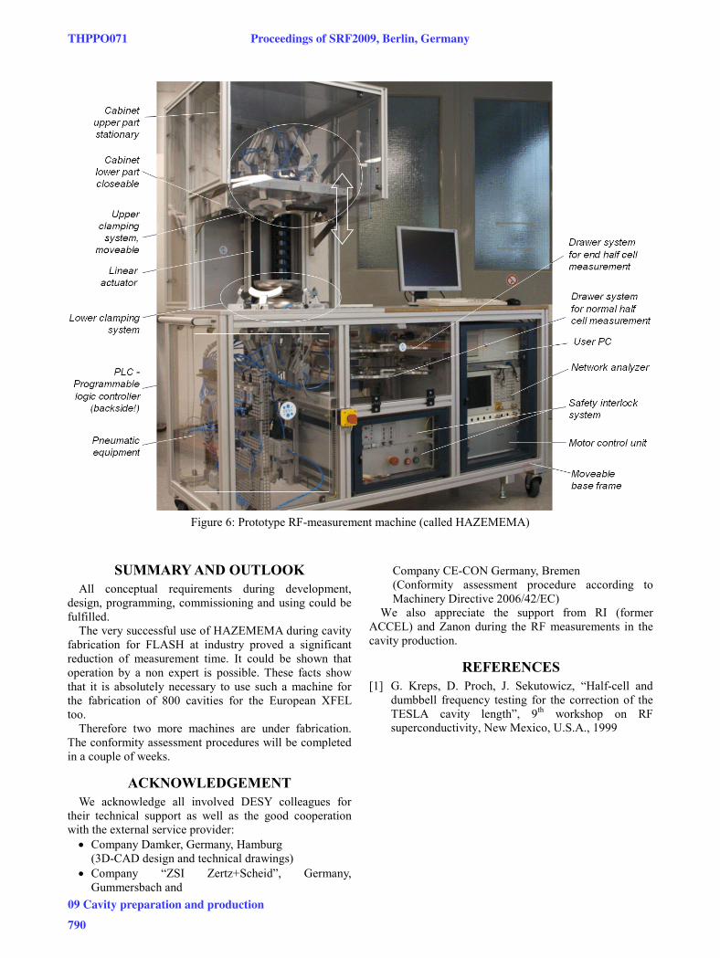
Figure 6: Prototype RF-measurement machine (called HAZEMEMA)
SUMMARY AND OUTLOOK All conceptual requirements during development,
design, programming, commissioning and using could be fulfilled.
The very successful use of HAZEMEMA during cavity fabrication for FLASH at industry proved a significant reduction of measurement time. It could be shown that operation by a non expert is possible. These facts show that it is absolutely necessary to use such a machine for the fabrication of 800 cavities for the European XFEL too.
Therefore two more machines are under fabrication. The conformity assessment procedures will be completed in a couple of weeks.
ACKNOWLEDGEMENT We acknowledge all involved DESY colleagues for
their technical support as well as the good cooperation with the external service provider: • Company Damker, Germany, Hamburg
(3D-CAD design and technical drawings) • Company “ZSI Zertz+Scheid”, Germany,
Gummersbach and
Company CE-CON Germany, Bremen (Conformity assessment procedure according to Machinery Directive 2006/42/EC)
We also appreciate the support from RI (former ACCEL) and Zanon during the RF measurements in the cavity production.
REFERENCES [1] G. Kreps, D. Proch, J. Sekutowicz, “Half-cell and
dumbbell frequency testing for the correction of the TESLA cavity length”, 9th workshop on RF superconductivity, New Mexico, U.S.A., 1999
THPPO071 Proceedings of SRF2009, Berlin, Germany
09 Cavity preparation and production
790