Embed Size (px)
Citation preview

INT-0322-XX Page 1
Precision Mass Flow Controller
Model 829 Series
Operating Manual

INT-0322-XX
Warranty
This product is warranted to the original purchaser for a period of one year from the date of purchase to be free of defects in material or workmanship. Under this warranty the product will be repaired or replaced at manufacturer’s option, without charge for parts or labor when the product is carried or shipped prepaid to the factory together with proof of purchase. This warranty does not apply to cosmetic items, nor to products that are damaged, defaced or otherwise misused or subjected to abnormal use. Where consistent with state law, the manufacturer shall not be liable for consequential economic, property, or personal injury damages. The manufacturer does not warrant or assume responsibility for the use of its products in life support applications or systems.
Conformity / Supplemental Information: The product complies with the requirements of the Low Voltage Directive 2006/95/ EC and the EMC Directive 2004/108/EC and carries the CE Marking accordingly. Contact the manufacturer for more information.
Notice: The manufacturer reserves the right to make any changes and improvements to the products described in this manual at any time and without notice. This manual is copyrighted. This document may not, in whole or in part, be copied, reproduced, translated, or converted to any electronic medium or machine readable form, for commercial purposes, without prior written consent from the copyright holder.
Note: Although we provide assistance on our products both personally and through our literature, it is the complete responsibility of the user to determine the suitability of any product to their application.
The manufacturer does not warrant or assume responsibility for the use of its products in life support applications or systems.

INT-0322-XX 3
Thank you for purchasing a Matheson Mass Flow Controller.
Please take the time to read the information contained in this manual. This will
help to ensure that you get the best possible service from your instrument. This
manual covers the following Matheson instruments:
829 Series Mass Gas Flow Controllers
Unless otherwise noted, the instructions in this manual are applicable to all of
the above instruments.
Full specifications for each device can be found on pages 42 and 43.
Please contact Matheson at 1-800-828-4313 if you have any questions
regarding the use or operation of this device.

INT-0322-XX 4
TABLE OF CONTENTS Page
GETTING STARTED 6
MOUNTING 6
PLUMBING 7
POWER AND SIGNAL CONNECTIONS 8
INPUT SIGNALS 8
Analog Input Signal 8
RS-232 Digital Input Signal 10
OUTPUT SIGNALS 10
RS-232 Digital Output Signal 10
Standard Voltage (0-5 Vdc) Output Signal 10
Optional Current (4-20 mA) Output Signal 11
DISPLAYS AND MENUS 11
MAIN 11
Gas Absolute Pressure 11
Gas Temperature 11
Set-Point. 11
Volumetric Flow Rate 12
Mass Flow Rate 12
Flashing Error Message 13
SELECT MENU 14
CONTROL SETUP 15
Set-Point Source 15
Loop Variable 16
On / Off Auto-tare 16
PID Tuning 17
GAS SELECT 19
Composer 20
COMMUNICATION SELECT 22
Unit ID 22
Baud 22
MISCELLANEOUS 22
MISC1 23
Zero Band 23
Pressure Averaging 23
Flow Averaging 23
LCD Contrast 23
MISC2 24
Standard Temperature and Pressure 24
DIAG TEST 25
Rotate Display 25
MANUFACTURER DATA 25
RS-232 Output and Input 26

INT-0322-XX 5
Configuring HyperTerminal® 26
Streaming Mode 27
Changing from Streaming to Polling Mode 27
Sending a Set-Point via RS-232 28
To adjust the P & D terms via RS-232 28
Gas Select 29
Creating and Deleting Gas Mixtures using RS-232 30
Collecting Data 31
Data Format 32
Sending a Simple Script File to HyperTerminal® 33
Operating Principle 33
Standard Gas Data Tables 32
Gas Lists with Viscosities, Densities and Compressibilities 36
Troubleshooting 39
Maintenance and Recalibration 41
829 Technical Specifications 42
RJ45 Pin-Out Diagram 44

INT-0322-XX 6
GETTING STARTED
Mass Flow Controller shown with an upstream valve configuration and connection
port fittings
MOUNTING
829 -Series Gas Flow Controllers have holes on the bottom for mounting to
flat panels. See page 43.
Small valve controllers can usually be mounted in any position.
No straight runs of pipe are required upstream or downstream of the controller.
Control Valve
Power Jack
RJ45 Connector
Display Screen
Inlet Connection Port
Outlet Connection Port
Flow Direction Arrow

INT-0322-XX 7
PLUMBING
Your controller is shipped with plastic plugs fitted in the port openings.
To lessen the chance of contaminating the flow stream do not remove
these plugs until you are ready to install the device.
Make sure that the gas will flow in the direction indicated by the flow arrow.
Standard 829 Series Gas Flow Controllers have compression inlet and outlet
port connections. Other fittings such as NPT , VCR, and other specialty fittings
are available.
The inlet and outlet port sizes (process connections) for different flow ranges
are shown on page 42.
Do not use thread sealing Teflon® tape on compression fittings.
On NPT threaded connections, Do not wrap the first two threads. This will
minimize the possibility of getting tape into the flow stream and flow body.
Do not use pipe dopes or sealants on the process connections as these
compounds can cause permanent damage to the controller should they get
into the flow stream.
When changing fittings, carefully clean any tape or debris from the port threads.
We recommend the use of in-line sintered filters to prevent large particulates
from entering the measurement head of the instrument. Suggested maximum
particulate sizes are as follows:
15 microns for units with FS flow ranges between 0-2 sccm and 0-1 slpm.
50 microns for units with FS flow ranges of 0-1 slpm or more.
PRESSURE
Maximum operating line pressure is 150 psig (1 MPa).
If the line pressure is higher than 150 psig (1 MPa), use a pressure regulator upstream
from the flow controller to reduce the pressure to 150 psig (1 MPa) or less.
INT-0322-XX 8
POWER AND SIGNAL CONNECTIONS
Power can be supplied to your controller through either the power jack or the RJ45
connector.
An AC to DC adapter which converts line AC power to DC voltage and current as
specified below is required to use the power jack.
829 controllers require a 12-30Vdc power supply with a 2.1 mm female
positive center plug capable of supplying 250 mA.
NOTE: 4-20mA analog output requires at least 15 Vdc.
1 2 3 4 5 6 7 8
RJ45 Device
8 7 6 5 4 3 2 1
RJ45 Cable
INPUT SIGNALS
Analog Input Signal
Apply analog input to Pin 7.
1. RS-232 Receive 2. Ground 3. Analog Output 4. RS-232 Transmit 5. Power Supply 6. Power Supply 7. Analog Input 8. Ground
Standard 0-5 Vdc is the standard analog input signal. Apply the 0-5 Vdc input
signal to pin 7, with common ground on pin 8.
Optional 4-20 mA: If specified at time of order, a 4-20 mA input signal can be
applied to pin 7, with common ground on pin 8.
NOTE: This is a current sinking device. The receiving circuit is essentially a
250 ohm resistor to ground.

INT-0322-XX 9

INT-0322-XX 10
RS-232 Digital Input Signal
To use the RS-232 input signal, connect the RS-232 Output Signal (Pin 5), the
RS-232 Input Signal (Pin 3), and Ground (Pin 8) to your computer serial port as
shown below. (See page 25 for details on accessing RS-232)
Serial Cable End PC Serial Port
OUTPUT SIGNALS
RS-232 Digital Output Signal
To use the RS-232 output signal, it is necessary to connect the RS-232 Output
Signal (Pin 4), the RS-232 Input Signal (Pin 1), and Ground (Pin 8) to your
computer serial port as shown. (See page 25 for details on accessing RS-232
output.)
Standard Voltage (0-5 Vdc) Output Signal
829 -Series flow controllers equipped with a 0-5 Vdc (optional 0-10 Vdc) will
have this output signal available on Pin 3. This output is generally available in
addition to other optionally ordered outputs. This voltage is usually in the range
of 0.010 Vdc for zero flow and 5.0 Vdc for full-scale flow. The output voltage is
linear over the entire range. Ground for this signal is common on Pin 8.
Optional Current (4-20 mA) Output Signal
If your controller was ordered with a 4-20 mA current output signal, it will
be available on Pin 3. (See the Calibration Data Sheet that shipped with your
controller to determine which output signals were ordered.) The current signal
is 4 mA at 0 flow and 20 mA at the controller’s full scale flow. The output
current is linear over the entire range. Ground for this signal is common on Pin
8. (Current output units require 15-30Vdc power.)
5 4 3 2 1
9 8 7 6
1 2 3 4 5
6 7 8 9

INT-0322-XX 11
DISPLAYS AND MENUS
The device screen defaults to Main display as soon as power is applied to the controller.
Note: See page 24 to rotate the display 180°.
Main
The Main display shows pressure,
temperature, set-point, volumetric flow
and mass flow.
Pressing the button adjacent to a
parameter will make that parameter
the primary display unit.
By hitting the MENU button at the
bottom right of the screen you will
enter the Select Menu display.
Select Menu
From Select Menu you can change
the selected gas, interact with your
RS-232 settings, read manufacturer’s
data or access the control set-up
display.
Push MAIN to return to the Main display.
GAS SELECT
CONTROL SETUP
PSI #+13.60 +21.50 0.00
SET
SCCM
+0.00 CCM
+0.00 CCM
MENU/ TOTAL
Select Menu

INT-0322-XX 12
MAIN
This mode defaults on power up, with mass flow as the primary displayed parameter.
The following parameters are displayed in the Main mode.
Gas Absolute Pressure: This sensor references hard vacuum and reads incoming pressure both above and below local atmospheric pressure. This parameter is moved to the primary display by pushing the button above PSIA.
The engineering unit associated with absolute pressure is pounds per square inch absolute (psia). This can be converted
to gage pressure (psig) by subtracting local atmospheric pressure from the absolute pressure reading:
PSIG = PSIA – (Local Atmospheric Pressure)
Gas Temperature: 829 Series flow controllers measure the incoming temperature of the gas flow. The temperature is displayed in degrees Celsius (°C). This parameter is moved to the primary display by pushing the button above °C.
Pushing the button again allows you to select 0C (Celsius), 0K (Kelvin), 0F (Fahrenheit) or 0R (Rankine) for the temperature scale.
To select a temperature scale, use the UP and DOWN buttons to position the arrow in front of the desired scale.
Press SET to record your selection and return to the MAIN display. The selected
temperature scale will be displayed on the screen.
Set Point: The set-point (SETPT) is shown in the upper right of the display.
For information on changing the set-point see SETPT SOURCE, page 18.
Volumetric Flow Rate: This parameter is located in the lower left of the display. It is moved to the primary display by pushing the button below CCM in this example. Your display may show a different unit of measure.
PSIA
+13.
#C +21.50
SET+0.00
+0.00 CCM
+0.00 MENU/ SCCM TOTAL
SE

INT-0322-XX 13
Mass Flow Rate: The mass flow rate is the volumetric flow rate corrected to a
standard temperature and pressure (typically 14.696 psia and 21.1 °C).
This parameter is located in the lower middle of the display. It can be moved to
the primary display by pushing the button below SCCM in this example. Your
display may show a different unit of measure preceded by the letter S.
To get an accurate volumetric or mass flow rate, the gas being measured
must be selected. See Gas Select, page 18.
MENU: Pressing MENU switches the screen to the Select Menu display.
Flashing Error Message: An error message (MOV = mass overrange, VOV
= volumetric overrange, POV = pressure overrange, TOV = temperature
overrange) flashes when a measured parameter exceeds the range of the
sensor. When any item flashes, neither the flashing parameter nor the
mass flow measurement is accurate. Reducing the value of the flashing parameter
to within specified limits will return the unit to normal operation and accuracy.
If the unit does not return to normal operation contact Matheson.

INT-0322-XX 14
MISC1
BA M
UNIT IDA
BAUD 1920
BA M
SELECT MENU
From Select Menu you can change the selected gas, interact with your
RS-232 settings, read manufacturer’s data and access the control setup and
miscellaneous screens.
Press the button next to the desired operation to bring that function to the screen.
Manufacturer Data
Control Setup
An explanation for each screen can be found on the following pages.
Miscellaneous Communications Select
UP
PA SETPT 0.000 Select Menu
GAS SELECT
CONTROL
+ SCCM Air
+0.0 +0.0
SELE
Gas Select Main
SETPT
SETPT +0.0
ON

INT-0322-XX 15
SETPT SOUR
LOV
SETPT +0.
AUO
PI M
CONTROL SETUP
Control Setup is accessed by pressing the button below Control Setup on the
Select Menu display. From this screen you can select your set-point source,
choose a loop variable and adjust the PID terms.
Press BACK to return to the Select Menu
display.
Press MAIN to return to the MAIN display
SETPT SOURCE – Pressing the button
above SETPT SOURCE will allow you to
select how the set point will be conveyed
to your controller.
Use the line-up and line-down buttons
to move the arrow in front of the desired
option. Then press SET.
Press CANCEL to return to the previous
display.
The controller will ignore any set-point
except that of the selected set-point source and it will remember which input is
selected even if the power is disconnected.
RS-232 refers to a remote digital RS-232
set-point applied via a serial connection
to a computer or PLC as described in the
installation and RS-232 sections of this
manual. Use this setting with the BCL-9
and control or mixing software.
Front Panel refers to a set-point applied
directly at the controller.
Front Panel input must be selected
prior to changing the set-point at
the device.
Analog refers to a remote analog set-
point applied to Pin 7 of the RJ45 connector as described in the installation
section of this manual.
Use this setting when connecting to Matheson’s 8284A Dynablender Plus, or
827A single channel controller.
The standard analog input is 0-5 Vdc. If nothing is connected to Pin 7, and the
controller is set for analog control, the device will generate random set-point
values.
SETPT refers to the set-point. This parameter may be changed using the display
only if FRONT PANEL is selected as the Input. Press SETPT. Then use SELECT to
choose the decimal with the arrow and the UP and DOWN buttons to change
the value. Press SET to record your value. Press CLEAR to return to zero.
UP
>RS232
DO
FRONT PANEL ANALOG
CANCEL SET
INT-0322-XX 16
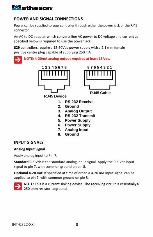
CONTROL SETUP (continued) LOOP VAR—Pressing the LOOP VAR
button on the Control Setup screen will
allow you to change what variable is
controlled.
Use the line-up and line-down buttons
to move the arrow in front of the desired
option.
When the mass flow controller is supplied
with the control valve upstream of the
electronics portion of the system, the unit
can be set to control on outlet pressure
(absolute pressures only) or volumetric
flow rate, instead of mass flow rate.
The change from mass to volume can
usually be accomplished without much, if
any, change in the P and D settings.
When you change from controlling
flow to controlling pressure,
sometimes fairly radical changes
must be made to the P & D variables. See
page 16 – PID TUNING.
Contact Matheson if you are having
difficulties with this procedure.
ON AUTO / OFF AUTO—refers to the
standard auto-tare or “auto-zero” feature.
The auto-tare feature automatically tares
(takes the detected signal as zero) the unit when it receives a zero set-point for
more than two seconds.
A zero set-point results in the closing of the valve and a known “no flow”
condition. This feature makes the device more accurate by periodically
removing any cumulative errors associated with drift.
It is recommended that the controller be left in the default auto-tare ON
mode unless your specific application requires that it be turned off.
U DO>Mass Volumetric Pressure
CANCEL
SETPT SOUR
LOV
SETPT +0.
AUO
PI M

INT-0322-XX 17
PID TUNING
PID Values determine the performance
and operation of your proportional control
valve. These terms dictate control speed,
control stability, overshoot and oscillation.
All units leave the factory with a generic
tuning designed to handle most applications.
If you encounter issues with valve stability,
oscillation or speed, fine tuning these
parameters may resolve the problem.
Matheson controllers allow you to adjust
the Proportional, Integral and Differential
terms of the PID control loop.
To change the PID loop parameters, push
the button below PID.
Press LOOP TYPE. Then use the UP and
DOWN buttons to select the appropriate
PID control algorithm. Press SET.
See the following page for descriptions
of the PID Loop Types (PID Control
Algorithms).
P refers to the Proportional term of the
PID loop.
I refers to the Integral term of the PID loop.
D refers to the Differential term of the PID
loop.
Press P, I or D. Then use SELECT to choose
the digit with the arrow and the UP and
DOWN buttons to change the value. Press
SET to record your value. Press CLEAR to
return to zero.
Before changing the P, I or D
parameter, please record the initial
value so that it can be returned to
the factory setting if necessary.
Valve tuning can be complex. If you
would like assistance, please contact
Matheson for technical support.
P 00100
0000I
0250D
BALOTY M
U DO> PD PD2I
CAN SE
SETPT SOURCE LOOP
VAR SETPT +0.0
AUTO ON
PID MAIN

INT-0322-XX 18
The PD algorithm is the PID algorithm used on most Matheson controllers.
It is divided into two segments:
The first compares the process value to the set-point to generate a proportional
error. The proportional error is multiplied by the ‘P’ gain, with the result added
to the output drive register.
The second operates on the present process value minus the process value during
the immediately previous evaluation cycle. This ‘velocity’ term in multiplied by
the ‘D’ gain, with the result subtracted from the output drive register.
The above additions to and subtractions from the output drive register
are carried over from process cycle to process cycle, thus performing the
integration function automatically.
Increasing the ‘P’ gain will promote the tendency of the system to overshoot,
ring, or oscillate.
Increasing the ‘D’ gain will reduce the tendency of the system to overshoot.
The PD2I algorithm is a PID algorithm used primarily for high performance
pressure and flow control applications.
It exhibits two basic differences from the PD algorithm that most controllers utilize.
1. Instead of applying a damping function based upon the rate of change of the
process value, it applies a damping function based upon the square of the rate of
change of the process value.
2. The damping function is applied directly to the proportional error term
before that term is used in the proportional and integral functions of the
algorithm. This provides a certain amount of ‘look ahead’ capability in the
control loop.
Because of these differences, you will note the following:
1. Increasing ‘P’ gain can be used to damp out overshoot and slow oscillations
in pressure controllers. You will know that ‘P’ gain is too high, when the
controller breaks into fast oscillations on step changes in set-point. On flow
controllers, too high a ‘P’ gain results in slower response times. Too low a ‘P’
gain results in overshoot and/or slow oscillation. A good starting value for ‘P’
gain is 200.
2. If the unit was originally shipped with the PD2I algorithm selected, the
‘D’ gain value should be left at or near the factory setting because it relates
primarily to the system phase lags. If you are changing from the default
algorithm to the PD2I algorithm, you should start with a ‘D’ gain value of 20.
3. The ‘I’ gain is used to control the rate at which the process converges
to the set-point, after the initial step change. Too low a value for ‘I’ gain
shows up as a process value that jumps to near the set-point and then takes
awhile to converge the rest of the way. Too high a value for ‘I’ gain results in
oscillation. A good starting value for the ‘I’ gain is 200.

INT-0322-XX 19
GAS SELECT
Gas Select allows you to set your
device to up to 150 standard gases and
mixes. You can also use COMPOSER to
program and store up to 20 additional
gas mixes.
Gas Select is accessed by pressing the
button below GAS SELECT on the Select
Menu display.
To select a gas, use the UP and DOWN
buttons to position the arrow in front of
the desired gas category.
» Recent: Eight most recent selections
» Standard: Gases and mixes (page 33)
» Factory Custom: Present only if customer
requested gases were added at the factory
» COMPOSER User Mixes: Gas mixes
programmed by the user (page 19)
» Bioreactor (page 35)
» Breathing (page 36)
» Chromatography (page 38)
» Fuel (page 37)
» Laser (page 37)
» O2 Concentrator (page 38)
» Pure Non-Corrosive (page 33)
» Stack (page 38)
» Welding (page 34)
Press PAGE to view a new page in the
gas category list.
Press SELECT to view the gases in the
selected category. Align the arrow with the desired gas. Press SET to record your
selection and return to the MAIN display. The selected gas will be displayed on
the screen.
Note: Gas Select may not be available on units ordered with a custom gas or blend.
See pages 33 -38 for a full list of gases in each category.
UP DOWN
CANCEL
U DOWN
Laser

INT-0322-XX 20
COMPOSER
Composer allows you to program
and save up to 20 custom gas mixes
containing 2 to 5 component gases
found in the gas lists (pages 33-38). The
minimum resolution is 0.01%.
Composer is accessed by selecting
COMPOSER User Mixes on the GAS
SELECT display.
Press SET when the arrow is aligned
with Add Mix.
Name the mix by pressing the UP and
DOWN buttons for letters, numerals
and symbols.
CHANGE CASE – Toggles the letter
case. Letters remain in selected case
until CHANGE CASE is pushed again.
Press SET to save the name.
After naming the mix, press ADD GAS
and select the gas category and the
component gas.
Select the digit with arrow and adjust
the % with the UP and DOWN buttons.
Press set to save. Add up to 4 more
gases as needed. The total must equal
100% or an error message will appear.
GAS OPTNS allows you to adjust the
percentage of the constituents or
delete a gas from the mix. Gas mixes
cannot be adjusted after they have
been saved.
UP DOWN
CAN SE
UP DOWN
CANCELBACK/
SE
EDIT NAME
OPTNS
CANCELBAC
SE

INT-0322-XX 21
Once the mix has been saved, you
may press CREATE SIMILAR to
compose an additional mix based
on the mix you have just saved.
This CREATE SIMILAR option is not
available after leaving this screen.
Press CREATE NEW to add a
completely new mix.
Press SELECT MIXTURE to bring the
custom mix onto the MAIN display.
SELECTDIGIT
Percent of
50.0
BACK/
SELECTDIGIT
Percent of Ar
30.0
BACK/
SELECTDIGIT
Percent of He
20.0
BACK/
ADD GAS GAS
OPTNS
COMPOSER Mix: MyGAS
50% Air
CREATENEW
CREATE SIMILAR
COMPOSER USER MIX
MyGas
SELECT

INT-0322-XX 22
COMMUNICATION SELECT
Access Communication Select by pressing
the button above RS232 COMM on the
Select Menu display.
Unit ID – Valid unit identifiers are the
letters A-Z and @. The identifier allows
you to assign a unique address to each
device so that multiple units can be
connected to a single RS-232 computer
port.
Press UNIT ID. Use the UP and DOWN
buttons to change the Unit ID. Press SET to
record the ID. Press Reset to return to the
previously recorded Unit ID.
Any Unit ID change will take effect when
Communication Select is exited.
If the symbol @ is selected as the Unit
ID, the device will enter streaming mode
when Communication Select is exited.
See RS-232 Communications (page 25) for
information about the streaming mode.
Baud – Both this instrument and your
computer must send/receive data at the
same baud rate. The default baud rate for
this device is 19200 baud.
Press BAUD. Use the UP and DOWN
buttons to select the baud rate that
matches your computer. The choices are
38400, 19200, 9600, or 2400 baud. Press
SET to record the baud rate.
Any baud rate change will not take effect
until power to the unit is cycled.
UNIT ID UP C DOWN
C SET
BAUD DOWN UP
19200
UNIT IDA
1920BAUD
BACK MAIN

INT-0322-XX 23
MISCELLANEOUS
Miscellaneous is accessed by pressing the MISC button on the Select Menu display.
Next select either MISC1 or MISC2.
MISC1 will display as shown at left.
ZERO BAND refers to Display Zero Deadband. Zero
deadband is a value below which the display jumps
to zero. This deadband is often desired to prevent
electrical noise from showing up on the display as
minor flows or pressures that do not exist. Display
Zero Deadband does not affect the analog or
digital signal outputs.
ZERO BAND can be adjusted between 0 and
3.2% of the sensor’s Full Scale (FS).
Press ZERO BAND. Then use SELECT to choose
the digit with the arrow and the UP and DOWN
buttons to change the value. Press SET to record
your value. Press CLEAR to return to zero.
Pressure Averaging and Flow Averaging may
be useful to make it easier to read and interpret
rapidly fluctuating pressures and flows. Pressure
and flow averaging can be adjusted between 1
(no averaging) and 256 (maximum averaging).
These are geometric running averages where
the number between 1 and 256 can be
considered roughly equivalent to the response
time constant in milliseconds.
This can be effective at “smoothing” high frequency process oscillations such as
those caused by diaphragm pumps.
Press PRESS AVG. Then use SELECT to choose the digit with the arrow and the UP and
DOWN buttons to change the value. Press SET to record your value. Press CLEAR to
return to zero.
Press FLOW AVG. Then use SELECT to choose the digit
with the arrow and the UP and DOWN buttons to
change the value. Press SET to record your value. Press
CLEAR to return to zero.
Setting a higher number will equal a smoother
LCD CONTRAST: The display contrast can be
adjusted between 0 and 30, with zero being the
lightest and 30 being the darkest. Use the UP and
DOWN buttons to adjust the contrast. Press SET
when you are satisfied. Press CANCEL to return to
the MISC display.
display.
ZERO BAND
PRESS AVG
FLOW AVG
BACK CONTRAST MAIN
UP DOWN SELECT
0.0
UP DOWN
11
>

INT-0322-XX 24
MISC2 will display as shown at left.
STP refers to the functions that allow your
selection of standard temperature and
pressure conditions. This feature is generally
useful for comparison purposes to other
devices or systems using different STP
parameters.
The STP menu is comprised of the STP TEMP
and STP PRESS screens.
STP TEMP allows you to select from seven
standard temperature protocols. The arrow
position will automatically default to the
currently stored value.
Once a selection has been made and recorded
using the SET button, a change acknowledgement
message will be displayed on screen.
Selecting RETURN will revert screen to the
Main display. If the SET selection is already
the currently stored value, a message
indicating that fact will appear.
STP PRESS enables you to select from one of
two standard pressure settings.
The arrow position will automatically default
to the currently stored value.
Once a selection has been made and recorded using the SET button, a change
acknowledgement message will be displayed on screen.
Selecting RETURN will revert screen to the Main display. If the SET selection is
already the currently stored value, a message indicating that fact will appear.
STP TEMP Display STP PRESS Display
UP DOWN 0 C 15
> 20 15.56 C
21.11 C 25 C 37 C
STP CHANGED
RETURN SET
UP DOWN
> 1 atm 14.696 1 bar 100KPa
--- STP ALREADY SET --- RETURN SET
STP TEST DIAG ROTATE
DISP
BACK MAIN
TEMP STP
PRESS STP
BACK MAIN

INT-0322-XX 25
MOD MTRN-10090
10/7/20110/9/2014
D
BACK MAIN
DIAG TEST: This diagnostic screen displays
the initial register values configured by the
factory, which is useful for noting factory
settings prior to making any changes. It
is also helpful for troubleshooting with
Matheson customer service personnel.
Select the DIAG TEST button from the MISC2
screen to view a list of select register values.
Pressing the SCROLL button will cycle the
display through the register screens. An
example screen is shown at left.
Press ROTATE DISP and SET to Inverted 180° if your device is inverted. The
display and buttons will rotate together.
MANUFACTURER DATA
Manufacturer Data is accessed by pressing
the MFG DATA button on the Select Menu
display.
The initial display shows the name and
telephone number of the manufacturer.
Press MODEL INFO to show important
information about your flow device
including the model number, serial
number, and date of manufacture.
Press BACK to return to the MFG DATA
display.
Push MAIN to return to the Main display.
SCROLL R8: AP Sig 7871 R9: Temp Sig 39071 R10: DP Side 9986 R11: DP Brdg 36673 R13: AP Brdg 36673 R16: Meter Func199 R18: Power Up 32768
BACK MAIN

INT-0322-XX 26
RS-232 Output and Input
Configuring HyperTerminal®:
1. Open your HyperTerminal® RS-232 terminal program (installed under the
“Accessories” menu on all Microsoft Windows® operating systems).
2. Select “Properties” from the file menu.
3. Click on the “Configure” button under the “Connect To” tab. Be sure the
program is set for: 19,200 baud (or matches the baud rate selected in the RS-
232 communications menu on the meter) and an 8-N-1-None (8 Data Bits,
No Parity, 1 Stop Bit, and no Flow Control) protocol.
4. Under the “Settings” tab, make sure the Terminal Emulation is set to ANSI
or Auto Detect.
5. Click on the “ASCII Setup” button and be sure the “Send Line Ends with Line
Feeds” box is not checked and the “Echo Typed Characters Locally” box and
the “Append Line Feeds to Incoming Lines” boxes are checked. Those settings
not mentioned here are normally okay in the default position.
6. Save the settings, close HyperTerminal® and reopen it.
Streaming Mode
In the default Polling Mode, the screen should be blank except the blinking cursor. In
order to get the data streaming to the screen, hit the “Enter” key several times to clear
any extraneous information. Type “*@=@” followed by “Enter” (or using the RS-232
communication select menu, select @ as identifier and exit the screen). If data still
does not appear, check all the connections and COM port assignments.
Streaming Mode – Advanced
The streaming data rate is controlled by register 91. The recommended default rate
of data provision is once every 50 milliseconds and this is suitable for most purposes.
If a slower or faster streaming data rate is desired, register 91 can be changed to a
value from 1 millisecond to 65535 milliseconds, or slightly over once every minute.
Below approximately 40 milliseconds, data provision will be dependent upon
how many parameters are selected. Fewer data parameters can be streamed
more quickly than more. It is left to the user to balance streaming speed with
number of parameters streamed.
To read register 91, type “*r91” followed by “Enter”.
To modify register 91, type “*w91=X”, where X is a positive integer from 1 to
65535, followed by “Enter”.
To return to the recommended factory default streaming speed, type “*w91= 50”.
Changing From Streaming to Polling Mode:
When the meter is in the Streaming Mode, the screen is updated approximately
10-60 times per second (depending on the amount of data on each line) so that
the user sees the data essentially in real time. It is sometimes desirable, and
necessary when using more than one unit on a single RS-232 line, to be able to
poll the unit.
In Polling Mode the unit measures the flow normally, but only sends a line of data
when it is “polled”. Each unit can be given its own unique identifier or address.

INT-0322-XX 27
Unless otherwise specified each unit is shipped with a default address of capital A.
Other valid addresses are B thru Z.Once you have established communication
with the unit and have a stream of information filling your screen:
1. Type *@=A followed by “Enter” (or using the RS-232 communication select
menu, select A as identifier and exit the screen) to stop the streaming mode
of information. Note that the flow of information will not stop while you
are typing and you will not be able to read what you have typed. Also, the
unit does not accept a backspace or delete in the line so it must be typed
correctly. If in doubt, simply hit enter and start again. If the unit does not
get exactly what it is expecting, it will ignore it. If the line has been typed
correctly, the data will stop.
2. You may now poll the unit by typing A followed by “Enter”. This does an
instantaneous poll of unit A and returns the values once. You may type A
“Enter” as many times as you like. Alternately you could resume streaming
mode by typing *@=@ followed by “Enter”. Repeat step 1 to remove the
unit from the streaming mode.
3. To assign the unit a new address, type *@=New Address, e.g. *@=B. Care
should be taken not to assign an address to a unit if more than one unit is
on the RS-232 line as all of the addresses will be reassigned. Instead, each
should be individually attached to the RS-232 line, given an address, and
taken off. After each unit has been given a unique address, they can all be
put back on the same line and polled individually.
Sending a Set-point via RS-232: To send a set-point via RS-232, “Serial” must be
selected under the “Input” list in the control set up mode.
Method 1: Set-point may be set in floating point in serial communication using
serial command (UnitID)SX.YZ
Example: AS4.54 results in Unit ID A changing set-point to 4.54.
Method 2: Type in a number between 0 and 65535 (2% over range), where 64000
denotes full-scale flow rate, and hit “Enter”.
The set-point column and flow rates should change accordingly. If they do not,
try hitting “Enter” a couple of times and repeating your command. The formula
for performing a linear interpolation is as follows:
Value = (Desired Set-point X 64000) / Full Scale Flow Range
For example, if your device is a 100 slpm full-scale unit and you wish to apply a
set-point of 35 slpm you would enter the following value:
22400 = (35 slpm X 64000) / 100 slpm
If the controller is in polling mode as described in Changing from Streaming
Mode to Polling Mode, the set-point must be preceded by the address of the
controller. For example, if your controller has been given an address of D, the
set-point above would be sent by typing:D22400 followed by “Enter”

INT-0322-XX 28
To adjust the Proportional and Differential (P&D) terms via RS-232:
Type *@=A followed by “Enter” to stop the streaming mode of information.
To adjust the “P” or proportional term of the PID controller, type *R21 followed
by “Enter”.
The computer will respond by reading the current value for register 21 between
0-65535. It is good practice to write this value down so you can return to the
factory settings if necessary. Enter the value you wish to try by writing the new
value to register 21. For example, if you wished to try a “P” term of 220, you
would type *W21=220 followed by “Enter” where the bold number denotes the
new value.
The computer will respond to the new value by confirming that 21=220. To
see the effect of the change you may now poll the unit by typing A followed
by “Enter”. This does an instantaneous poll and returns the values once. You
may type A “Enter” as many times as you like. Alternately you could resume
streaming mode by typing *@=@ followed by “Enter”. Repeat step 3 to remove
the unit from the streaming mode.
To adjust the “D” or proportional term of the PID controller, type *R22 followed
by “Enter”.
The computer will respond by reading the current value for register 22 between
0-65535. It is good practice to write this value down so you can return to the
factory settings if necessary. Enter the value you wish to try by writing the new
value to register 22. For example, if you wished to try a “D” term of 25, you
would type *W22=25 followed by “Enter” where the bold number denotes the
new value.
The computer will respond to the new value by confirming that 22=25. To see the
effect of the change you may now poll the unit by typing A followed by “Enter”.
This does an instantaneous poll and returns the values once. You may type A
“Enter” as many times as you like. Alternately you could resume streaming mode
by typing *@=@ followed by “Enter”. Repeat.
You may test your settings for a step change by changing the set-point. To do
this type A32000 (A is the default single unit address, if you have multiple
addressed units on your RS-232 line the letter preceding the value would change
accordingly.) followed by “Enter” to give the unit a ½ full scale set-point. Monitor
the unit’s response to the step change to ensure it is satisfactory for your needs.
Recall that the “P” term controls how quickly the unit goes from one set-point to
the next, and the “D” term controls how quickly the signal begins to “decelerate”
as it approaches the new set-point (controls the overshoot).

INT-0322-XX 29
Gas Select – The selected gas can be changed via RS-232 input. To change the
selected gas, enter the following commands:
In Polling Mode: Address$$#<Enter> (e.g. B$$#<Enter>)
Where # is the number of the gas selected from the table below. Note that
this also corresponds to the gas select menu on the flow controller screen (the
Standard gas category is shown in the example below):
# GAS
0 Air Air 1 Argon Ar 2 Methane CH4 3 Carbon Monoxide CO 4 Carbon Dioxide CO2 5 Ethane C2H6 6 Hydrogen H2 7 Helium He 8 Nitrogen N2 9 Nitrous Oxide N2O
10 Neon Ne 11 Oxygen O2 12 Propane C3H8 13 normal-Butane n-C4H10 14 Acetylene C2H2 15 Ethylene C2H4 16 iso-Butane i-C4H10 17 Krypton Kr 18 Xenon Xe 19 Sulfur Hexafluoride SF6 20 75% Argon / 25% CO2 C-25 21 90% Argon / 10% CO2 C-10 22 92% Argon / 8% CO2 C-8 23 98% Argon / 2% CO2 C-2 24 75% CO2 / 25% Argon C-75 25 75% Argon / 25% Helium HE-75 26 75% Helium / 25% Argon HE-25
27 90% Helium / 7.5% Argon / 2.5% CO2
(Praxair - Helistar® A1025) A1025
28 90% Argon / 8% CO2 / 2% Oxygen
(Praxair - Stargon® CS) Star29
29 95% Argon / 5% Methane P-5
For example, to select Propane, enter: $$12<Enter>

INT-0322-XX 30
Creating and Deleting Gas Mixtures with COMPOSER™ using RS-232
Note: All commands must be prefixed with the unit ID letter. The unit should not be in streaming mode.
You may create and store up to 20 gas mixtures containing up to five constituent gases each. The constituent gases must be chosen from the existing list of gases installed on the device (which may vary model to model). Please see pages 40 – 47 for lists of gases and their corresponding gas numbers.
Create a Gas Mixture
To create a gas mixture, enter a single-line command according to the following formula:
[Unit ID] GM [Gas Name] [Gas Mix Number] [Percent 1] [Gas Number 1]
[Percent 2] [Gas Number 2] …etc. etc.
Notes: Do not type the brackets. There should be only one space between all items. Any percentages less than 1, should have a leading zero before the decimal (i.e. 0.25 for .25%). Trailing zeros are not necessary but they are allowed to help visualize the percentages on screen (as in the example). The sum of all percentages must be 100.00 otherwise an error will occur.
Here is an example of a three gas mixture for a new gas called “MyMix1” (50% O2, 49.5% Helium, and .5% Neon), stored in user location #236, where the unit ID of the device is “A”:
A GM MyMix1 236 50.00 11 49.50 7 0.50 10 <ENTER>
Gas Name: Name your mixture using a maximum of 6 characters.
Gas Mix Number: COMPOSER™ user mixes have Matheson gas numbers between 236 and 255. You can assign any number in this range to your new mixture. If another mixture with the same number exists, it will be overwritten, even if that gas is currently selected on the unit. If you enter a 0 here, the new mix will be assigned the next available number between 236 and 255.
Percent 1: The percentage of the first constituent gas. The percentage of each constituent must be between 0.01 and 99.99. Values entered beyond two decimal points will be rounded to the nearest 0.01%.
Gas Number 1: The Matheson gas number of the first constituent gas.
Percent 2: The percentage of the second constituent gas. Values entered
beyond two decimal points will be rounded to the nearest 0.01%.
Gas Number 2: The Matheson gas number of the second constituent gas.
Additional Gases: (Optional) The above pattern of [Percent] + [Gas Number]
may be repeated for additional constituent gases (up to a total of five).
Upon success, the unit ID (if set) is returned followed by a space. The number of the gas mixture is then returned, followed by the percentages and names of each constituent in the mix. If the gas mix is not successfully created, a "?" is returned, and you must start over.
Delete a Gas Mixture
To delete a gas mixture, enter: [Unit ID]GD [Gas Number]: The number of the
COMPOSER™ user mixture you wish to delete from the unit
Only COMPOSER™ user mixtures can be deleted with this command.
On success, the unit ID (if set) is returned followed by a space and the number of the gas deleted. If the gas is not successfully deleted, a "?" is returned.

INT-0322-XX 31
Collecting Data:
The RS-232 output updates to the screen many times per second. Very short-term events can be captured simply by disconnecting (there are two telephone symbol icons at the top of the HyperTerminal® screen for disconnecting and connecting) immediately after the event in question. The scroll bar can be driven up to the event and all of the data associated with the event can be selected, copied, and pasted into Microsoft® Excel® or other spreadsheet program as described below.
For longer term data, it is useful to capture the data in a text file. With the desired data streaming to the screen, select “Capture Text” from the Transfer Menu. Type in the path and file name you wish to use. Push the start button. When the data collection period is complete, simply select “Capture Text” from the Transfer Menu and select “Stop” from the sub-menu that appears.
Data that is selected and copied, either directly from HyperTerminal® or from a text file can be pasted directly into Excel®. When the data is pasted it will all be in the selected column. Select “Text to Columns...” under the Data menu in Excel® and a Text to Columns Wizard (dialog box) will appear.
Make sure that “Fixed Width” is selected under Original Data Type in the first dialog box and click “Next”. In the second dialog box, set the column widths as desired, but the default is usually acceptable. Click on “Next” again. In the third dialog box, make sure the column data format is set to “General”, and click “Finish”. This separates the data into columns for manipulation and removes symbols such as the plus signs from the numbers. Once the data is in this format, it can be graphed or manipulated as desired. For extended term data capture see page 31.
Data Format:
The data stream on the screen represents the flow parameters of the main mode in the units shown on the display.
For mass flow controllers, there are six columns of data representing pressure, temperature, volumetric flow, mass flow, set-point, and the selected gas
The first column is absolute pressure (normally in psia), the second column is temperature (normally in °C), the third column is volumetric flow rate (in the units specified at time of order and shown on the display), the fourth column is mass flow (also in the units specified at time of order and shown on the display), the fifth column is the currently selected set-point value, the sixth column designates the currently selected gas. For instance, if the controller was ordered in units of scfm, the display on the controller would read 2.004 scfm and the last two columns of the output below would represent volumetric flow and mass flow in cfm and scfm respectively.
+014.70 +025.00 +02.004 +02.004 2.004 Air
+014.70 +025.00 +02.004 +02.004 2.004 Air
+014.70 +025.00 +02.004 +02.004 2.004 Air
+014.70 +025.00 +02.004 +02.004 2.004 Air
Pressure Temp Vol. Flow Mass Flow Set Point Gas
829 -Series Mass Flow Controller Data Format

INT-0322-XX 32
Sending a Simple Script File to HyperTerminal®
It is sometimes desirable to capture data for an extended period of time. Standard
streaming mode information is useful for short term events, however, when
capturing data for an extended period of time, the amount of data and thus the
file size can become too large very quickly. Without any special programming
skills, the user can use HyperTerminal® and a text editing program such as
Microsoft® Word® to capture text at user defined intervals.
1. Open your text editing program, MS Word for example.
2. Set the cap lock on so that you are typing in capital letters.
3. Beginning at the top of the page, type A<Enter> repeatedly. If you’re using MS
Word, you can tell how many lines you have by the line count at the bottom of the
screen. The number of lines will correspond to the total number of times the flow
device will be polled, and thus the total number of lines of data it will produce.
For example: A
A
A
A
A
will get a total of six lines of data from the flow meter, but you can enter as
many as you like.
The time between each line will be set in HyperTerminal.
4. When you have as many lines as you wish, go to the File menu and select save.
In the save dialog box, enter a path and file name as desired and in the “Save as
Type” box, select the plain text (.txt) option. It is important that it be saved as a
generic text file for HyperTerminal to work with it.
5. Click Save.
6. A file conversion box will appear. In the “End Lines With” drop down box, select
CR Only. Everything else can be left as default.
7. Click O.K.
8. You have now created a “script” file to send to HyperTerminal. Close the file
and exit the text editing program.
9. Open HyperTerminal and establish communication with your flow device as
outlined in the manual.
10. Set the flow device to Polling Mode as described in the manual. Each time you
type A<Enter>, the meter should return one line of data to the screen.
11. Go to the File menu in HyperTerminal and select “Properties”.
12. Select the “Settings” tab.
13. Click on the “ASCII Setup” button.
14. The “Line Delay” box is defaulted to 0 milliseconds. This is where you will tell
the program how often to read a line from the script file you’ve created. 1000
milliseconds is one second, so if you want a line of data every 30 seconds, you

INT-0322-XX 33
would enter 30000 into the box. If you want a line every 5 minutes, you would
enter 300000 into the box.
15. When you have entered the value you want, click on OK and OK in the
Properties dialog box.
16. Go the Transfer menu and select “Send Text File…” (NOT Send File…).
17. Browse and select the text “script” file you created.
18. Click Open.
19. The program will begin “executing” your script file, reading one line at a time
with the line delay you specified and the flow device will respond by sending one
line of data for each poll it receives, when it receives it.
You can also capture the data to another file as described in the manual under
“Collecting Data”. You will be simultaneously sending it a script file and capturing
the output to a separate file for analysis.
Operating Principle
All 829 -Series Gas Flow Controllers are based on the accurate measurement of
volumetric flow. The volumetric flow rate is determined by creating a pressure drop
across a unique internal restriction, known as a Laminar Flow Element (LFE), and
measuring differential pressure across it. The restriction is designed so that the gas
molecules are forced to move in parallel paths along the entire length of the passage;
hence laminar (streamline) flow is established for the entire range of operation of the
device. Unlike other flow measuring devices, in laminar flow meters the relationship
between pressure drop and flow is linear.
STANDARD GAS DATA TABLES: Matheson has incorporated the latest data sets
from NIST (including their REFPROP 9 data where available) in our products’
built-in gas property models. Be aware that the calibrators that you may be
using may be checking against older data sets such as the widely distributed Air
Liquide data. This may generate apparent calibration discrepancies of up to 0.6%
of reading on well behaved gases and as much as 3% of reading on some gases
such as propane and butane, unless the standard was directly calibrated on the
gas in question.
As the older standards are phased out, this difference in readings will cease to
be a problem. If you see a difference between the Matheson meter and your
in-house standard, in addition to calling Matheson at 800-828-4313, call the
manufacturer of your standard for clarification as to which data set they used in
their calibration. This comparison will in all likelihood resolve the problem.

GAS SELECT > Standard:
829 Controllers will display: Acetylene, Air, Argon, Butane, Carbon Dioxide, Carbon Monoxide, Ethane, Ethylene (Ethene), Helium, Hydrogen, Iso-Butane, Krypton, Methane, Neon, Nitrogen, Nitrous Oxide, Oxygen, Propane, Sulfur Hexafluoride, Xenon, A-25, A-75, A1025, C-2, C-8, C-10, C-25, C-75, P-5, Star29.
PURE NON-CORROSIVE GASES 25°C 0°C
Gas Number
Short Nam
Long Name Absolut
e Viscosit
Density 14.696 PSIA
Compressibilty 14.696 PSIA
Absolute Viscosit
Density 14.696 PSIA
Compressibilty 14.696 PSIA 14 C2H2 Acetylene 104.44800 1.07200 0.9928000 97.374 1.1728 0.9905
0 Air Air 184.89890 1.18402 0.9996967 172.574 1.2930 0.9994 1 Ar Argon 226.23990 1.63387 0.9993656 210.167 1.7840 0.9991
16 i-C4H10 i-Butane 74.97846 2.44028 0.9735331 68.759 2.6887 0.9645 13 n-C4H10 n-Butane 74.05358 2.44930 0.9699493 67.690 2.7037 0.9591 4 CO2 Carbon Dioxide 149.31840 1.80798 0.9949545 137.107 1.9768 0.9933 3 CO Carbon Monoxide 176.49330 1.14530 0.9996406 165.151 1.2505 0.9993
60 D2 Deuterium 126.59836 0.16455 1.0005970 119.196 0.1796 1.0006 5 C2H6 Ethane 93.54117 1.23846 0.9923987 86.129 1.3550 0.9901
15 C2H4 Ethylene (Ethene) 103.18390 1.15329 0.9942550 94.697 1.2611 0.9925 7 He Helium 198.45610 0.16353 1.0004720 186.945 0.1785 1.0005 6 H2 Hydrogen 89.15355 0.08235 1.0005940 83.969 0.0899 1.0006
17 Kr Krypton 251.32490 3.43229 0.9979266 232.193 3.7490 0.9972 2 CH4 Methane 110.75950 0.65688 0.9982472 102.550 0.7175 0.9976
10 Ne Neon 311.12640 0.82442 1.0004810 293.822 0.8999 1.0005 8 N2 Nitrogen 178.04740 1.14525 0.9998016 166.287 1.2504 0.9995 9 N2O Nitrous Oxide 148.41240 1.80888 0.9945327 136.310 1.9779 0.9928
11 O2 Oxygen 205.50210 1.30879 0.9993530 191.433 1.4290 0.9990 12 C3H8 Propane 81.46309 1.83204 0.9838054 74.692 2.0105 0.9785 19 SF6 Sulfur Hexafluoride 153.53200 6.03832 0.9886681 140.890 6.6162 0.9849 18 Xe Xenon 229.84830 5.39502 0.9947117 212.157 5.8980 0.9932
33

WELDING GASES 25°C 0°C Gas
NumbeShort
Long Name Absolute
Density 14.696
Compressibilty 14.696
Absolute
Density 14.696
Compressibilty 14.696
23 C-2 2% CO2 / 98% Ar 224.71480 1.63727 0.9993165 208.673 1.7877 0.998993 22 C-8 8% CO2 / 92% Ar 220.13520 1.64749 0.9991624 204.199 1.7989 0.9987964 21 C-10 10% CO2 / 90% Ar 218.60260 1.65091 0.9991086 202.706 1.8027 0.9987278
140 C-15 15% CO2 / 85% Ar 214.74960 1.65945 0.9989687 198.960 1.8121 0.9985493 141 C-20 20% CO2 / 80% Ar 210.86960 1.66800 0.9988210 195.198 1.8215 0.9983605 20 C-25 25% CO2 / 75% Ar 206.97630 1.67658 0.9986652 191.436 1.8309 0.9981609
142 C-50 50% CO2 / 50% Ar 187.53160 1.71972 0.9977484 172.843 1.8786 0.9969777 24 C-75 75% CO2 / 25% Ar 168.22500 1.76344 0.9965484 154.670 1.9271 0.995401 25 He-25 25% He / 75% Ar 231.60563 1.26598 0.9996422 216.008 1.3814 0.9999341
143 He-50 50% He / 50% Ar 236.15149 0.89829 0.9999188 220.464 0.9800 1.00039 26 He-75 75% He / 25% Ar 234.68601 0.53081 1.0001954 216.937 0.5792 1.000571
144 He-90 90% He / 10% Ar 222.14566 0.31041 1.0003614 205.813 0.3388 1.00057 27 A1025 90%He/7.5%Ar/2.5%CO2 214.97608 0.31460 1.0002511 201.175 0.3433 1.000556
28 Star29 Stargon CS 90%
Ar / 8% CO2 / 2% O2
219.79340 1.64099 0.9991638 203.890 1.7918 0.998798
34
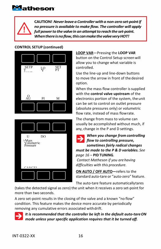
BIOREACTOR GASES 25°C 0°C Gas
NumbeShort
Long Name Absolute
Density 14.696
Compressibilty 14.696
Absolute
Density 14.696
Compressibilty 14.696
145 Bio-5M 5% CH4 / 95% CO2 148.46635 1.75026 0.9951191 136.268 1.9134 0.9935816 146 Bio-10M 10% CH4 / 90% CO2 147.54809 1.69254 0.9952838 135.383 1.8500 0.993893 147 Bio-15M 15% CH4 / 85% CO2 146.55859 1.63484 0.9954484 134.447 1.7867 0.9941932 148 Bio-20M 20% CH4 / 80% CO2 145.49238 1.57716 0.9956130 133.457 1.7235 0.994482 149 Bio-25M 25% CH4 / 75% CO2 144.34349 1.51950 0.9957777 132.407 1.6603 0.9947594 150 Bio-30M 30% CH4 / 70% CO2 143.10541 1.46186 0.9959423 131.290 1.5971 0.9950255 151 Bio-35M 35% CH4 / 65% CO2 141.77101 1.40424 0.9961069 130.102 1.5340 0.9952803 152 Bio-40M 40% CH4 / 60% CO2 140.33250 1.34664 0.9962716 128.834 1.4710 0.9955239 153 Bio-45M 45% CH4 / 55% CO2 138.78134 1.28905 0.9964362 127.478 1.4080 0.9957564 154 Bio-50M 50% CH4 / 50% CO2 137.10815 1.23149 0.9966009 126.025 1.3450 0.9959779 155 Bio-55M 55% CH4 / 45% CO2 135.30261 1.17394 0.9967655 124.462 1.2821 0.9961886 156 Bio-60M 60% CH4 /40% CO2 133.35338 1.11642 0.9969301 122.779 1.2193 0.9963885 157 Bio-65M 65% CH4 /35% CO2 131.24791 1.05891 0.9970948 120.959 1.1564 0.9965779 158 Bio-70M 70% CH4 / 30% CO2 128.97238 1.00142 0.9972594 118.987 1.0936 0.9967567 159 Bio-75M 75% CH4 / 25% CO2 126.51146 0.94395 0.9974240 116.842 1.0309 0.9969251 160 Bio-80M 80% CH4 / 20% CO2 123.84817 0.88650 0.9975887 114.501 0.9681 0.9970832 161 Bio-85M 85% CH4 / 15% CO2 120.96360 0.82907 0.9977533 111.938 0.9054 0.9972309 162 Bio-90M 90% CH4 / 10% CO2 117.83674 0.77166 0.9979179 109.119 0.8427 0.9973684 163 Bio-95M 95% CH4 / 5% CO2 114.44413 0.71426 0.9980826 106.005 0.7801 0.9974957
35

BREATHING GASES 25°C 0°C
Gas Number
Short Nam
Long Name Absolute Viscosit
Density 14.696 PSIA
Compressibilty 14.696 PSIA
Absolute Viscosit
Density 14.696 PSIA
Compressibilty 14.696 PSIA164 EAN-32 32% O2 / 68% N2 186.86315 1.19757 0.9996580 174.925 1.3075 0.9993715
165 EAN 36% O2 / 64% N2 187.96313 1.20411 0.9996401 175.963 1.3147 0.9993508 166 EAN-40 40% O2 / 60% N2 189.06268 1.21065 0.9996222 176.993 1.3218 0.9993302 167 HeOx-20 20% O2 / 80% He 217.88794 0.39237 1.0002482 204.175 0.4281 1.000593 168 HeOx-21 21% O2 / 79% He 218.15984 0.40382 1.0002370 204.395 0.4406 1.000591 169 HeOx-30 30% O2 / 70% He 219.24536 0.50683 1.0001363 205.140 0.5530 1.000565 170 HeOx-40 40% O2 / 60% He 218.59913 0.62132 1.0000244 204.307 0.6779 1.000502 171 HeOx-50 50% O2 / 50% He 216.95310 0.73583 0.9999125 202.592 0.8028 1.000401 172 HeOx-60 60% O2 / 40% He 214.82626 0.85037 0.9998006 200.467 0.9278 1.000257 173 HeOx-80 80% O2 / 20% He 210.11726 1.07952 0.9995768 195.872 1.1781 0.9998019 174 HeOx-99 99% O2 / 1% He 205.72469 1.29731 0.9993642 191.646 1.4165 0.9990796 175 EA-40 Enriched Air-40% O2 189.42518 1.21429 0.9996177 177.396 1.3258 0.9993261 176 EA-60 Enriched Air-60% O2 194.79159 1.24578 0.9995295 182.261 1.3602 0.9992266 177 EA-80 Enriched Air-80% O2 200.15060 1.27727 0.9994412 186.937 1.3946 0.9991288
178 Metabol Metabolic Exhalant (16% O2
/ 78.04% N2 / 5% CO2 / 0.96% Ar)
180.95936 1.20909 0.9994833 170.051 1.3200 0.9992587
36

FUEL GASES 25°C 0°C
Gas Number
Short Nam
Long Name Absolute Viscosit
Density 14.696 PSIA
Compressibilty 14.696 PSIA
Absolute Viscosit
Density 14.696 PSIA
Compressibilty 14.696 PSIA185 Syn Gas-
1 40% H2 + 29% CO+ 20% CO2 + 11% CH4 155.64744 0.79774 0.9989315 144.565 0.8704 0.9992763
186 Syn Gas-2
64% H2 + 28% CO+ 1% CO2 + 7% CH4 151.98915 0.43715 1.0001064 142.249 0.4771 1.000263 187 Syn Gas-
3 70% H2 + 4% CO+ 25% CO2 + 1% CH4 147.33686 0.56024 0.9991225 136.493 0.6111 0.9997559
188 Syn Gas-4
83%H2+14%CO+3%CH4 133.63682 0.24825 1.0003901 125.388 0.2709 1.000509 189 Nat Gas-1 93%CH4/3%C2H6/1%C3H8/2%N2/1%C
O2 111.77027 0.70709 0.9979255 103.189 0.7722 0.9973965
190 Nat Gas-2 95% CH4 / 3% C2H6 / 1% N2 / 1% CO2 111.55570 0.69061 0.9980544 103.027 0.7543 0.9974642
191 Nat Gas-3 95.2% CH4 / 2.5% C2H6 / 0.2% C3H8 /
0.1% C4H10 / 1.3% N2 / 0.7% CO2
111.49608 0.68980 0.9980410 102.980 0.7534 0.9974725
192 Coal Gas 50% H2 / 35% CH4 / 10% CO/ 5% C2H4 123.68517 0.44281 0.9993603 115.045 0.6589 0.996387 193 Endo 75% H2 + 25% N2 141.72100 0.34787 1.0005210 133.088 0.3797 1.000511 194 HHO 66.67% H2 / 33.33% O2 180.46190 0.49078 1.0001804 168.664 0.5356 1.000396
195 HD-5 LPG 96.1% C3H8 / 1.5% C2H6 /
0.4% C3H6 / 1.9% n-C4H10
81.45829 1.83428 0.9836781 74.933 2.0128 0.9784565
196 HD-10 LPG 85% C3H8 / 10% C3H6 / 5% n-C4H10
81.41997 1.85378 0.9832927 74.934 2.0343 0.9780499
LASER GASES 25°C 0°C
Gas Numbe
Short
Long Name Absolute
Density 14.696
Compressibilty 14.696
Absolute
Density 14.696
Compressibilty 14.696
179 LG-4.5 4.5% CO2 / 13.5% N2 / 82% He 199.24300 0.36963 1.0001332 187.438 0.4033 1.000551 180 LG-6 6% CO2 / 14% N2 / 80% He 197.87765 0.39910 1.0000471 186.670 0.4354 1.00053 181 LG-7 7% CO2 / 14% N2 / 79% He 197.00519 0.41548 0.9999919 186.204 0.4533 1.000514 182 LG-9 9% CO2 / 15% N2 / 76% He 195.06655 0.45805 0.9998749 184.835 0.4997 1.000478 183 HeNe-9 9% Ne / 91% He 224.68017 0.22301 1.0004728 211.756 0.2276 1.000516 184 LG-9.4 9.4% CO2 / 19.25% N2 / 71.35% 193.78311 0.50633 0.9998243 183.261 0.5523 1.000458
37

O2 CONCENTRATOR GASES 25°C 0°C Gas
NumbeShort
Long Name Absolute
Density 14.696
Compressibilty 14.696
Absolute
Density 14.696
Compressibilty 14.696
197 OCG-89 89% O2 / 7% N2 / 4% Ar 204.53313 1.31033 0.9993849 190.897 1.4307 0.9990695 198 OCG-93 93% O2 / 3% N2 / 4% Ar 205.62114 1.31687 0.9993670 191.795 1.4379 0.9990499 199 OCG-95 95% O2 / 1% N2 / 4% Ar 206.16497 1.32014 0.9993580 192.241 1.4414 0.99904
STACK GASES 25°C 0°C
Gas Numbe
Short
Long Name Absolute
Density 14.696
Compressibilty 14.696
Absolute
Density 14.696
Compressibilty 14.696
200 FG-1 2.5% O2 / 10.8% CO2 / 85.7% N2 / 1% 175.22575 1.22550 0.9992625 165.222 1.3379 0.9990842 201 FG-2 2.9% O2 / 14% CO2 / 82.1% N2 / 1%
Ar 174.18002 1.24729 0.9991056 164.501 1.3617 0.9989417
202 FG-3 3.7% O2 / 15% CO2 / 80.3% N2 / 1% Ar
174.02840 1.25520 0.9990536 164.426 1.3703 0.9988933
203 FG-4 7% O2 / 12% CO2 / 80% N2 / 1% Ar 175.95200 1.24078 0.9991842 166.012 1.3546 0.9990116
204 FG-5 10% O2 / 9.5% CO2 / 79.5% N2 / 1% 177.65729 1.22918 0.9992919 167.401 1.3419 0.9991044 205 FG-6 13% O2 / 7% CO2 / 79% N2 / 1% Ar 179.39914 1.21759 0.9993996 168.799 1.3293 0.9991932
CHROMATOGRAPHY GASES 25°C 0°C
Gas Numbe
Short
Long Name Absolute
Density 14.696
Compressibilty 14.696
Absolute
Density 14.696
Compressibilty 14.696
29 P-5 5% CH4 / 95% Ar 223.91060 1.58505 0.9993265 207.988 1.7307 0.9990036 206 P-10 10% CH4 90% Ar 221.41810 1.53622 0.9992857 205.657 1.6774 0.99895
38

39
INT-0322-X
TROUBLESHOOTING
Display does not come on or is weak.
Check power and ground connections. Please reference the technical specifications
(page 42) to assure you have the proper power for your model.
Flow reading is approximately fixed either near zero or near full scale
regardless of actual line flow.
Differential pressure sensor may be damaged. A common cause of this problem
is instantaneous application of high-pressure gas as from a snap acting solenoid
valve upstream of the meter. If you suspect that your pressure sensor is
damaged please discontinue use of the controller and contact Matheson.
Displayed mass flow, volumetric flow, pressure or temperature is flashing and
message MOV, VOV, POV or TOV is displayed:
Our flow meters and controllers display an error message (MOV = mass
overrange, VOV = volumetric overrange, POV = pressure overrange, TOV =
temperature overrange) when a measured parameter exceeds the range of the
sensors in the device. When any item flashes on the display, neither the flashing
parameter nor the mass flow measurement is accurate. Reducing the value of
the flashing parameter to within specified limits will return the unit to normal
operation and accuracy. If the unit does not return to normal contact Matheson.
After installation, there is no flow.
Matheson 829 controllers incorporate normally closed valves and require a set-
point to operate. Check that your set-point signal is present and supplied to
the correct pin and that the correct set-point source is selected under the SETPT
SOURCE list in the control set up display. Also check that the unit is properly
grounded.
The flow lags below the set-point.
Be sure there is enough pressure available to make the desired flow rate. If
either the set-point signal line and/or the output signal line is relatively long, it
may be necessary to provide heavier wires (especially ground wiring) to negate
voltage drops due to line wire length. An inappropriate PID tuning can also
cause this symptom if the D term is too large relative to the P term. See pages
20 and 21 for more information on PID tuning.
Controller is slow to react to a set-point change or imparts an oscillation to the flow.
An inappropriate PID tuning can cause these symptoms. Use at conditions
considerably different than those at which the device was originally set up
can necessitate a re-tuning of the PID loop. See pages 16 and 17 for more
information on PID tuning.
The output signal is lower than the reading at the display.
This can occur if the output signal is measured some distance from the meter,
as voltage drops in the wires increase with distance. Using heavier gauge wires,
especially in the ground wire, can reduce this effect.

40
Meter does not agree with another meter I have in line.
Volumetric meters are affected by pressure drops. Volumetric flow meters
should not be compared to mass flow meters. Mass flow meters can be
compared against one another provided there are no leaks between the two
meters and they are set to the same standard temperature and pressure. Both
meters must also be calibrated (or set) for the gas being measured. 819 Series
mass flow meters are normally set to Standard Temperature and Pressure
conditions of 21.1 ° C and 14.696 psia. Note: it is possible to special order
meters with a customer specified set of standard conditions. The calibration
sheet provided with each meter lists its standard conditions.
When performing this comparison it is best to use the smallest transition
possible between the two devices. Using small transitions will minimize lag and
dead volume.
RS-232 Serial Communications is not responding.
Check that your meter is powered and connected properly. Be sure that the
port on the computer to which the meter is connected is active. Confirm that
the port settings are correct per the RS-232 instructions in this manual (Check
the RS-232 communications select screen for current meter readings). Close
Hyperterminal® and reopen it. Reboot your PC. See pages 9 and 25 for more
information on RS-232 signals and communications.
Slower response than specified.
829 Series Controllers feature a programmable Geometric Running Average
(GRA). Depending on the full scale range of the meter, it may have the GRA
set to enhance the stability/readability of the display, which would result in
slower perceived response time. Please see “Pressure Averaging” and “Flow
Averaging” on page 22.
Jumps to zero at low flow.
829 -Series Controllers feature a programmable zero dead band. The factory
setting is usually 0.5% of full scale. This can be adjusted between NONE and
3.2% of full scale. See page 22.
Discrepancies between old and new units.
Please see “Standard Gas Data Tables” explanation on page 32.

41
Maintenance and Recalibration
General: 829 Series Flow Controllers require minimal maintenance. They
have no moving parts. The single most important thing that affects the life
and accuracy of these devices is the quality of the gas being measured. The
controller is designed to measure CLEAN, DRY, NON-CORROSIVE gases.
Moisture, oil and other contaminants can affect the laminar flow elements.
We recommend the use of in-line sintered filters to prevent large particulates
from entering the measurement head of the instrument. Suggested maximum
particulate sizes are as follows:
20 microns for units with FS flow ranges between 0-2 sccm and 0-1 slpm.
50 microns for units with FS flow ranges of 0-1 slpm or more.
Recalibration: The recommended period for recalibration is once every year. A
label located on the side of the controller lists the most recent calibration date.
The controller should be returned to the factory for recalibration within one
year from the listed date. Before calling to schedule a recalibration, please note
the serial number on the back of the instrument. The Serial Number, Model
Number, and Date of Manufacture are also available on the Model Info display
(page 24).
Cleaning: 829 Series Flow Controllers require no periodic cleaning. If
necessary, the outside of the controller can be cleaned with a soft dry cloth.
Avoid excess moisture or solvents.
For repair, recalibration or recycling of this product contact:
Matheson
166 Keystone Drive
Montgomeryville, PA 18936
Ph: 800-828-4313
Web: www.mathesongas.com

42
Technical Data for Matheson 829 Mass Flow Controll ers 0 to 100 sccm Full Scale through 0 to 10 slpm Full Scale
Standard Operating Specifications (Contact Matheson for available options) Performance 829 Mass Flow Controller
Accuracy at calibration conditions after tare
± (0.8% of Reading + 0.2% of Full Scale)
High Accuracy at calibration conditions after tare
± (0.4% of Reading + 0.2% of Full Scale) High Accuracy option not available for units ranged under 5 sccm or over 500 slpm.
Repeatability ± 0.2% Full Scale
Zero Shift and Span Shift 0.02% Full Scale / ºCelsius / Atm Operating Range / Turndown
Ratio 0.5% to 100% Full Scale / 200:1 Turndown
Maximum Controllable Flow Rate 102.4% Full Scale
Typical Response Time 100 ms (Adjustable)
Warm-up Time < 1 Second
Operating Conditions 829 Mass Flow Controller
Mass Reference Conditions (STP) 25ºC & 14.696 psia (standard — others available on request)
Operating Temperature −10 to +50 ºCelsius
Humidity Range (Non–Condensing) 0 to 100%
Max. Internal Pressure (Static) 145 psig
Proof Pressure 175 psig
Mounting Attitude Sensitivity None
Valve Type Normally Closed
Ingress Protection IP40
Wetted Materials
303 & 302 Stainless Steel, Viton®, Heat Cured Silicone Rubber, Glass Reinforced Polyphenylene Sulfide, Heat Cured Epoxy, Aluminum, Gold, Brass, 430FR Stainless Steel, Silicon, Glass. If your application demands a different material, please contact Matheson.
Communications / Power 829 Mass Flow Controller
Monochrome LCD Display with integrated touchpad
Simultaneously displays Mass Flow, Volumetric Flow, Pressure and Temperature
Digital Input/Output Signal1 RS-232 Serial
Analog Input/Output Signal2 0-5 Vdc / 4-20 mA
Electrical Connection Options RJ45
Supply Voltage 12 to 30 Vdc (15-30 Vdc for 4-20 mA outputs)
Supply Current 0.250 Amp
1. The Digital Output Signal communicates Mass Flow, Volumetric Flow, Pressure and Temperature 2. The Analog Output Signal communicate your choice of Mass Flow, Volumetric Flow, Pressure or Temperature
Range Specific Specifications Full Scale Flow Mass
Controller Pressure Drop at FS Flow
(psid) venting to atmosphere Mechanical Dimensions
Process Connections 1
100 sccm to 500 sccm 1.0
4.1”H x 3.6”W x 1.1”D
1/8” NPT Female 1 slpm 1.5 2 slpm 3.0 5 slpm 2.0
10 slpm 5.5
1. Compatible with, Swagelok® tube, Parker®, face seal, push connect and compression adapter fittings. VCR and SAE connections upon request.

43
829 -Series: 0 - 100 sccm 0 - 200 sccm 0 - 500 sccm 0 - 1 slpm 0 - 2 slpm 0 - 3 slpm 0 - 5 slpm 0 - 10 slpm
100 sccm to 10 slpm approximate weight: 1.2lb

44
RJ45 Connector Pin-Outs
1 2 3 4 5 6 7 8
RJ45 Device
8 7 6 5 4 3 2 1
RJ45 Cable
1. RS-232 Receive 2. Ground 3. Analog Output 4. RS-232 Transmit 5. Power Supply 6. Power Supply 7. Analog Input 8. Ground
Serial Number:
Model Number:

Notes: