Embed Size (px)
Citation preview

S. Kotthoff, A. Goessel, C. Mueller, DESY, 22603 Hamburg, Germany
Abstract
For the series production of XFEL cryo modules, it isplanned to test all complete modules prior the installationin the XFEL tunnel. For the test stands in the AcceleratorModule Test Facility (AMTF), we have developed a newtechnical interlock. The interlock allows the observationof 8 individual analog signals per device (like temperature,pressure, light, free electrons) and can be fully remote con-trolled. Each channel has its own upper and lower remotecontrolled threshold. The channels will be customized withsensor specific module cards, which adapt the power needsand signal conditioning to the specifications of the differ-ent sensors. The local display is used as user interface andthe little space requirement makes the device quite suitable.An overview of functionality, internal features, connectiv-ity and extendability of the device is given.
MOTIVATION
In AMTF we need several new technical interlocks.Each of them, depending on the test stand, should havebetween 2 and 69 channels for different sensor types. InFLASH we are using up to now a modified interlock sys-tem from HERA, which works very stable, but there is sev-eral additional hardware needed (a VME (Versa ModuleEurocard) crate with digital IOs (Input Output), slow andfast ADCs (Analog-to-Digital Converter)), to get it partlyremote controlled. It requires still an operator in the field,if we like to adjust an interlock threshold.
Thus we decided to build for AMTF a more flexible sys-tem, which can be easily adjusted to the different test standsand needs to be available soon. A first proposal of the inter-lock configuration for a module test stand in AMTF can beseen in Fig. 1. There will be also vertical test stands (work-ing with CW (continuous wave) RF (radio frequency)) inthis hall, but there we need much less interlock channels(usual only the vacuum pressure and a He level). We liketo have an interlock, that fits to all of these environments.
REQUIREMENTS
As mentioned there is an existing interlock with somefeatures, which we will not miss in the new one:
• It uses one module card for each channel/sensor forthe signal conditioning, which makes it very flexible.
• This card takes care also for the power requirementof the sensor. E.g., a light detector will get ±15V; aPT100 will get a constant current, and so on.
Figure 1: Block diagram of the interlock configuration fora module test stand in AMTF.
• Each input signal will be filtered and amplified in ana-log technic. The threshold is a defined voltage level,which can be easily used with an analog comparatorin order to generate an alarm, if the input exceeds itslimits. For this reason there is no dead time betweensamples, and there is no external clock or triggeringneeded.
The big disadvantage up to now is the missing remotecontroll and the many external devices which are needed,in order to get some informations into the digital side ofdata processing. Here now the needed new features of theinterlock:
• It has to be fully remote controlled!
• There should be a test function, which makes it possi-ble to check that the sensor is functional including thesignal conditioning. It should no longer be neccessaryto enter an accelerator tunnel, dismount a sensor andfeed in some light (or whatever it likes), only to besure that it is still working right.
• There should be no software included in the interlocklogic. Original we considered to build it in standardTTL (HCMOS), but we realize very early that it will
DEVELOPMENT OF A REMOTE-CONTROLLEDCOUPLER-INTERLOCK FOR THE XFEL ACCELERATOR MODULE
TEST FACILITY (AMTF)
Proceedings of SRF2009, Berlin, Germany THPPO039
08 Ancillary systems
661

not be possible to be small in size. Thus we use acomplex programmable logic device (CPLD), whichworks without an external clock signal!
• As much as possible, the parts of the interlock shouldbe checked by the device itself.
• The device must be easily extendable. In the idealcase, the devices can be directly connected together,without the need of different hardware for this combi-nation.
• There must be some diagnostic possible on the deviceitself, to be fast if something doesn’t work.
In the first steps, we expect only some channels are needed,and we are more focused on the adhoc interlocking some-where in the field. For this application we like to havea standard connector for sensors (6 pins + shield), whichcan be connected directly. For the more fixed installationslike in AMTF we use normally a distribution box. So weplanned to build two different backplanes, one with all sen-sor signals in one connector, and one with the mentionedindividual sensor connectors.
DIAGNOSTICS
The interlock device can be divided in two parts: Thesignal conditioning, comparison and the logic of the in-terlock, which together takes care about the observed sen-sors/components. The second part is the microcontroller,which configures all the thresholds, module cards, interlocklogic and communicates with a DOOCS [3] (DistributedObject Oriented Control System) server via ethernet. Themicrocontroller is not involved in the interlock function it-self, thus in general it is possible to restart it, without anyinfluence on the active running interlock.
Diagnostics Local on the Device
On the front panel there are LEDs (Light EmittingDiode), which are showing in realtime the state of the in-terlock logic. For each channel there is an upper and loweralarm LED (red) and also an upper and lower mask LED(yellow), if such a limitation is not used. A seven segmentdisplay shows which alarm channel comes up first. Thereis also a LED which display if this device was the first onein the group of interlocks or if there is a different devicewhich is the reason (via the lock-line) that this one rises thealarm output. Additionally, there are reset buttons, whichcan reset only this interlock, or with the second button allinterlocks in the same RF group (if there are more than onecombined together).
The microcontroller is using a four line LC-Display,which allows the operator to read individual channel states(including the measured value and thresholds per channelin there calibrated real units, like a temperature in Kelvinshown in Fig. 2). Also all status bits are shown, in order to
get out, if an IC is not answering on one of the i2c (Inter-Integrated Circuit) buses, or a system voltage is missing.The network configuration and status can be seen, whichis the most usefull point, if the device cannot be accessedvia the network (for example if there is a bad/wrong DHCP(Dynamic Host Configuration Protocol) server acting in thesame network segment). (The device can be also config-ured to use static network addresses.)
It is not possible to change any settings through the LCD(Liquid Crystal Display) menu, this has to be done throughthe network connection.
Figure 2: Example of the LC-Display: A measured tem-perature and its high and low alarm limits.
Diagnostics Remotely via Ethernet
What informations we like to know from the de-vice? That depends; roughly there should be somwhere aDOOCS panel, which displays the actual signal values andtheir alarm states.
If there is a problem with this simple informations, thereare many possiblilities, what can go wrong. All stateswhich are shown via the LEDs (interlock state) and are vis-ible in the LC-Display menu are also accessable via ether-net. The ”data-set” structure allows to see the status of anyIC on the i2c buses, the set and readback values (if avail-able) and also if the setting succeeds.
Additionally, there is the possibility to set values via eth-ernet, therefore are two different accounts created. The nor-mal user can set all interlock relevant settings, like thresh-olds, channel masks and manual alarm. The admin ac-count has additionally the permission to change the inter-lock channel calibration or configuration and all system rel-evant settings (like network, module card power, process-ing on the i2c bus, ...). If there is any internal communica-tion channel not working, it will be shown in a sum statusbyte, which is returned on any communication access.
WORKING PRINCIPLE
In the block diagram (Fig. 3) the main functional groupsof the device are shown. The logic of the CPLD will getall individual alarm signals (two per channel) and also thealarm state of the other interlock devices (via the lock-line).It will get the reset information from the front-panel buttonsand also from other devices (via the reset-line). The statuswill be shown directly with several LEDs.
The microcontroller handles the network interface andmeasures the analog values with an internal 12 bit ADCdirectly. It can communicate with the CPLD, the DACs
THPPO039 Proceedings of SRF2009, Berlin, Germany
08 Ancillary systems
662
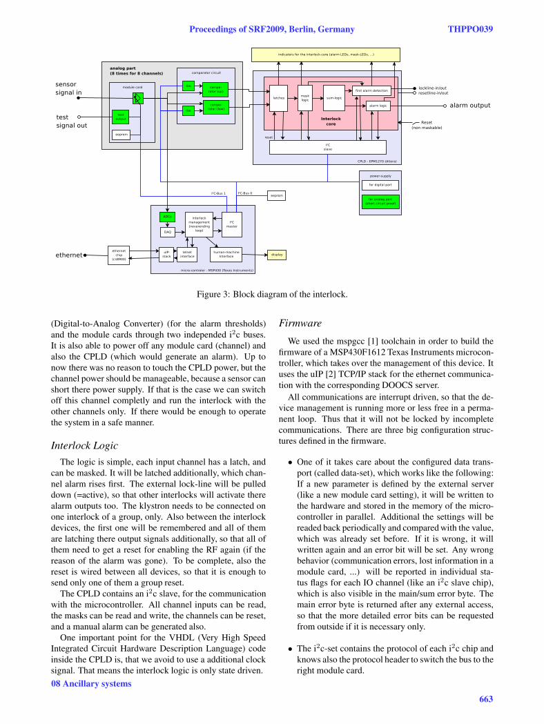
Figure 3: Block diagram of the interlock.
(Digital-to-Analog Converter) (for the alarm thresholds)and the module cards through two independed i2c buses.It is also able to power off any module card (channel) andalso the CPLD (which would generate an alarm). Up tonow there was no reason to touch the CPLD power, but thechannel power should be manageable, because a sensor canshort there power supply. If that is the case we can switchoff this channel completly and run the interlock with theother channels only. If there would be enough to operatethe system in a safe manner.
Interlock Logic
The logic is simple, each input channel has a latch, andcan be masked. It will be latched additionally, which chan-nel alarm rises first. The external lock-line will be pulleddown (=active), so that other interlocks will activate therealarm outputs too. The klystron needs to be connected onone interlock of a group, only. Also between the interlockdevices, the first one will be remembered and all of themare latching there output signals additionally, so that all ofthem need to get a reset for enabling the RF again (if thereason of the alarm was gone). To be complete, also thereset is wired between all devices, so that it is enough tosend only one of them a group reset.
The CPLD contains an i2c slave, for the communicationwith the microcontroller. All channel inputs can be read,the masks can be read and write, the channels can be reset,and a manual alarm can be generated also.
One important point for the VHDL (Very High SpeedIntegrated Circuit Hardware Description Language) codeinside the CPLD is, that we avoid to use a additional clocksignal. That means the interlock logic is only state driven.
Firmware
We used the mspgcc [1] toolchain in order to build thefirmware of a MSP430F1612 Texas Instruments microcon-troller, which takes over the management of this device. Ituses the uIP [2] TCP/IP stack for the ethernet communica-tion with the corresponding DOOCS server.
All communications are interrupt driven, so that the de-vice management is running more or less free in a perma-nent loop. Thus that it will not be locked by incompletecommunications. There are three big configuration struc-tures defined in the firmware.
• One of it takes care about the configured data trans-port (called data-set), which works like the following:If a new parameter is defined by the external server(like a new module card setting), it will be written tothe hardware and stored in the memory of the micro-controller in parallel. Additional the settings will bereaded back periodically and compared with the value,which was already set before. If it is wrong, it willwritten again and an error bit will be set. Any wrongbehavior (communication errors, lost information in amodule card, ...) will be reported in individual sta-tus flags for each IO channel (like an i2c slave chip),which is also visible in the main/sum error byte. Themain error byte is returned after any external access,so that the more detailed error bits can be requestedfrom outside if it is necessary only.
• The i2c-set contains the protocol of each i2c chip andknows also the protocol header to switch the bus to theright module card.
Proceedings of SRF2009, Berlin, Germany THPPO039
08 Ancillary systems
663

• The menu-set contains the function calls in order todisplay the human readable informations on the LCD.It knows also the actual functions of the buttons (up,down, ok, back). It distinguishs between menu dis-plays and function displays. The function displays areable to update the shown informations (like ADC val-ues) without a pressed button.
The firmware provides not only commands for the nor-mal interlock operation. There are also many commandsfor detailed diagnostic as well as the programming of mod-ule cards and the system configuration is foreseen.
MODULE CARDS
The designed module card interface is identical for eachdevice channel, so that the cards can be mixed like it isneeded. The sensor connector uses always 6 pins, whichare defined by the card only, and should contain in generalthe signal to measure, the power supply for the sensor anda test signal from the module card in order to test the rightfunction of the sensor.
The digital part of the card offers 8 free defined bits,which are used for switching between different low passfilters, gains, power supplies, to enable the test function orto enable a LED on the module card which can be used bythe DOOCS server to mark a channel for the maintenance.The memory on the card is used to store the ID, the cardlabel, calibrations and the labels of the 8 individual config-uration bits. The bit labels are used to show a readable stateof each bit in the display of the device.
Actual we build 3 different module cards.
• PT100(0) module card. The test function reduces theconstant current of the sensor.
• Analog-In module card, with a differential input for±1V and ±10V. It supports the sensor with ±15V anda test output with +15V. A low pass filter can be en-abled.
• The e- module card is similar to the Analog-In type,except that it measures the current on a 100 Ohm shuntand contains a floating voltage source (0V, ±15V,±30V).
The analog main board is able to switch off the power ofeach channel individually, if a external sensor is shortingthe power supply.
OUTLOOK
A series prototype of this interlock is just build and willbe tested as soon as possible. All cavity and module teststands for the XFEL will use this interlock type. Onlythe fast sensor channels need additional external ADCs(1MS/s), which are available from the controll system(DOOCS). The system allows to be as flexible as possi-ble, also during the cavity production it would be easilypossible to change the type of a channel.
REFERENCES
[1] mspgcc: A port of the GNU tools to the Texas InstrumentsMSP430 microcontrollers done by Chris Liechti and DmitryDiky. http://mspgcc.sourceforge.net/
[2] The open-source uIP TCP/IP stack was developed byAdam Dunkels of the Networked Embedded Systemsgroup at the Swedish Institute of Computer Science.http://www.sics.se/~adam/uip/index.php/Main Page
[3] K. Rehlich et al, DOOCS: an Object Oriented Control Sys-tem as the integrating part for the TTF Linac, ProceedingsICALEPCS ’97, Beijing, China. http://doocs.desy.de/
THPPO039 Proceedings of SRF2009, Berlin, Germany
08 Ancillary systems
664