Embed Size (px)
Citation preview
DESIGN OF LONGITUDINAL DECK SUPERSTRUCTURES
8.1 INTRODUCTION
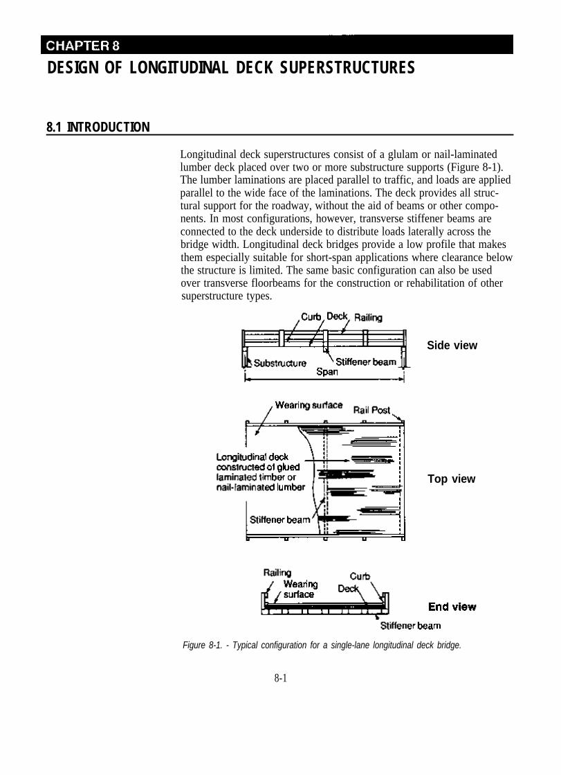
Longitudinal deck superstructures consist of a glulam or nail-laminated lumber deck placed over two or more substructure supports (Figure 8-1). The lumber laminations are placed parallel to traffic, and loads are applied parallel to the wide face of the laminations. The deck provides all structural support for the roadway, without the aid of beams or other components. In most configurations, however, transverse stiffener beams are connected to the deck underside to distribute loads laterally across the bridge width. Longitudinal deck bridges provide a low profile that makes them especially suitable for short-span applications where clearance below the structure is limited. The same basic configuration can also be used over transverse floorbeams for the construction or rehabilitation of other superstructure types.
Side view
Top view
Figure 8-1. - Typical configuration for a single-lane longitudinal deck bridge.
8-1

This chapter discusses the design requirements and considerations for longitudinal deck bridges constructed of glulam and nail-laminated sawn lumber. Railing and wearing surfaces for longitudinal decks are addressed in Chapters 10 and 11, respectively.
8.2 DESIGN CRITERIA AND DEFINITIONS
The design requirements addressed in this chapter are based on the 1983 edition of the AASHTO Standard Specifications for Highway Bridges, including interim specifications through 1987.1 The criteria related to design procedures and examples, loads, materials, live load deflection, and conditions of use are the same as those given for beam superstructures in Chapter 7, with the following exceptions.
LOADS Longitudinal decks are designed for the maximum forces and deflection produced by the design vehicle, assuming that wheel loads act as point loads in the direction of the deck span (AASHTO 3.25.2.3). AASHTO special provisions for reduced wheel loads for H 20-44 and HS 20-44 trucks do not apply to longitudinal decks.
CONDITIONS OF USE All deck components are designed using wet-condition stresses with the exception of transverse stiffener beams for watertight glulam decks. Based on recommendations of AITC, stiffener beams that are treated with oil-type preservatives and are located under a watertight glulam deck are assumed to remain within the range of dry-use conditions.4
8.3 LONGITUDINAL GLULAM DECK BRIDGES
Longitudinal glulam deck bridges consist of a series of glulam panels placed edge to edge across the deck width (Figure 8-2). They are practical for clear spans up to approximately 35 feet and are equally adaptable to single-lane and multiple-lane crossings. The panels are usually not interconnected with dowels or fasteners but are provided with transverse stiffener beams below the deck. These stiffener beams, which are bolted to the panels directly or with brackets, transfer loads between panels and give continuity to the system. They are also frequently used as a point of attachment for railing systems. As with glulam beam bridges, longitudinal glulam deck bridges can be prefabricated in a modular system that is pressure treated with preservatives after all required cuts and holes are made. This improves the bridge economy and longevity and reduces field erection time.
8-2
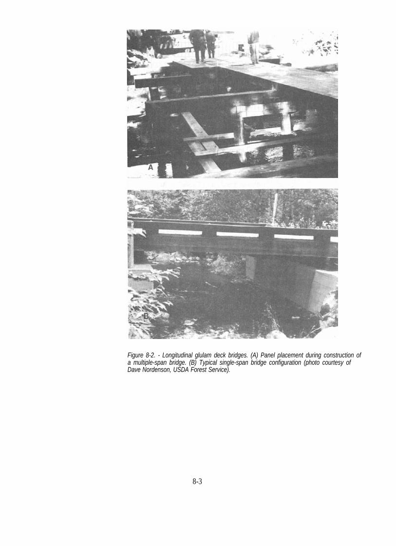
Figure 8-2. - Longitudinal glulam deck bridges. (A) Panel placement during construction of a multiple-span bridge. (B) Typical single-span bridge configuration (photo courtesy of Dave Nordenson, USDA Forest Service).
8-3
DESIGN PROCEDURES
Panel end views
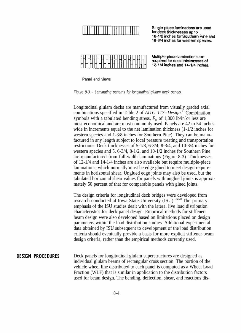
Figure 8-3. - Laminating patterns for longitudinal glulam deck panels.
Longitudinal glulam decks are manufactured from visually graded axial combinations specified in Table 2 of AITC 117--Design.3 Combination symbols with a tabulated bending stress, Fb, of 1,800 lb/in2 or less are most economical and are most commonly used. Panels are 42 to 54 inches wide in increments equal to the net lamination thickness (1-1/2 inches for western species and 1-3/8 inches for Southern Pine). They can be manufactured in any length subject to local pressure treating and transportation restrictions. Deck thicknesses of 5-1/8, 6-3/4, 8-3/4, and 10-3/4 inches for western species and 5, 6-3/4, 8-1/2, and 10-1/2 inches for Southern Pine are manufactured from full-width laminations (Figure 8-3). Thicknesses of 12-1/4 and 14-1/4 inches are also available but require multiple-piece laminations, which normally must be edge glued to meet design requirements in horizontal shear. Unglued edge joints may also be used, but the tabulated horizontal shear values for panels with unglued joints is approximately 50 percent of that for comparable panels with glued joints.
The design criteria for longitudinal deck bridges were developed from research conducted at Iowa State University (ISU).14,27,28 The primary emphasis of the ISU studies dealt with the lateral live load distribution characteristics for deck panel design. Empirical methods for stiffener-beam design were also developed based on limitations placed on design parameters within the load distribution studies. Additional experimental data obtained by ISU subsequent to development of the load distribution criteria should eventually provide a basis for more explicit stiffener-beam design criteria, rather than the empirical methods currently used.
Deck panels for longitudinal glulam superstructures are designed as individual glulam beams of rectangular cross section. The portion of the vehicle wheel line distributed to each panel is computed as a Wheel Load Fraction (WLF) that is similar in application to the distribution factors used for beam design. The bending, deflection, shear, and reactions dis-
8-4

tributed to each panel are assumed to be resisted by the entire panel cross section.
Sequential design procedures for longitudinal glulam deck bridges are given in the following steps. These procedures are based on ISU research and are valid for panels that are 3-1/2 to 4-1/2 feet wide and are provided with transverse stiffener beams. The basic sequence is to (1) estimate a panel thickness and width, (2) determine loads and load distribution criteria, (3) select an initial panel combination symbol based on bending, and (4) check the suitability of the panel in deflection and shear. The process is iterative in nature if panel dimensions are changed at any point during the design process. After a suitable panel size and grade are determined, stiffener beams and bearings are designed.
1. Define deck geometric requirements and design loads.a. Define geometric requirements for bridge span and width. The
effective deck span, L, is the distance measured center-to-center of the bearings. Deck width is the roadway width plus any additional width required for curb and railing systems.
b. Identify design vehicles (including overloads) and other applicable loads and AASHTO load combinations discussed in Chapter 6. Note design requirements for live load deflection and other site-specific requirements for geometry or loading.
2. Estimate panel thickness and width and compute section properties.Deck thickness and width must be estimated for initial calculations. Approximate maximum deck spans that may be used for estimating an initial deck thickness are shown in Table 8-1.
Panel width depends on the out-to-out structure width. Panels are 42 to 54 inches wide in multiples of 1-1/2 inches for western species or 1-3/8 inches for Southern Pine. The panels are normally designed to be of equal width, obtained by dividing the bridge width by a selected number of panels.
Based on the estimated panel dimensions, properties are computed for the panel cross section as follows:
8-5

Table 8-1. - Approximate maximum spans for longitudinal glulam deck bridges for purposes of estimating deck thickness.
A = panel area (in2) = wPt (8-1)
(8-2)
(8-3)
t = panel thickness (in.).
3. Compute panel dead load.Compute the uniform dead load, wDL, of the deck and wearing surface in lb/ft (or lb/in) of panel length using the unit material weights given in Chapter 6. Typical deck dead loads for various panel widths are given in Table 8-2. When railings and curbs are supported by transverse stiffener
8-6

Table 8-2. - Typical dead loads for longitudinal glulam deck panels.
beams, their dead load is normally assumed to be equally distributed to all panels. When railings and curbs are attached to the outside panel, their dead load is included with the dead load of the panel.
4. Determine Wheel Load Fraction for live load distribution.Longitudinal glulam panels are designed as individual members to resist applied loads. In the direction of the deck span, no longitudinal distribution of wheel loads is assumed, and wheel loads act as concentrated loads. The portion of the wheel line laterally distributed to each panel is based on the WLF. For live load moment, vertical shear, and deflection, the WLF is based on the panel width and span in feet and is specified separately for bridges designed for one traffic lane, and bridges designed for two or more traffic lanes (AASHTO 3.25.3.1):
8 -7

For bridges designed for one traffic lane, WLF is computed by
where WLF = the portion of the maximum force or deflection produced by one wheel line that is supported by one deck panel,
W = panel width (ft), andp
L = length of span for simple-span decks and the length of the shortest span for continuous-span decks, measured center to center of the bearings (ft).
For bridges designed for two or more traffic lanes, WF is computed by
5. Determine dead load and live load moment.Compute the maximum panel dead load moment based on the deck dead loads previously determined. Compute live load moment by multiplying the maximum moment for one wheel line of the design vehicle by the WLF:
MLL = MWL (WLF) (8-6)
where MLL = live load moment applied to one panel (in-lb), and
MWL = maximum moment produced by one wheel line of the design vehicle (in-lb).
Maximum simple-span moments for standard AASHTO vehicles are given in Table 16-8. For multiple-span continuous bridges, maximum moments are computed for the controlling truck or lane load by analyzing the deck as a continuous beam.
6. Compute bending stress and select a deck combination symbol.Compute deck bending stress by dividing the sum of the maximum live load and dead load bending moments by the panel section modulus (f b = M/Sy ). Based on the magnitude of the stress, select a panel combination symbol from Table 2 of AITC 117-Design, which provides the required bending capacity. As with transverse glulam decks, the most common combination symbols for longitudinal decks are No. 2 for western species (Fby = 1,800 lb/in2) and No. 47 for Southern Pine ( Fby = 1,750 lb/in2). Applied bending stress, fb must not be greater than the allowable bending stress, Fb', as computed by
8-8
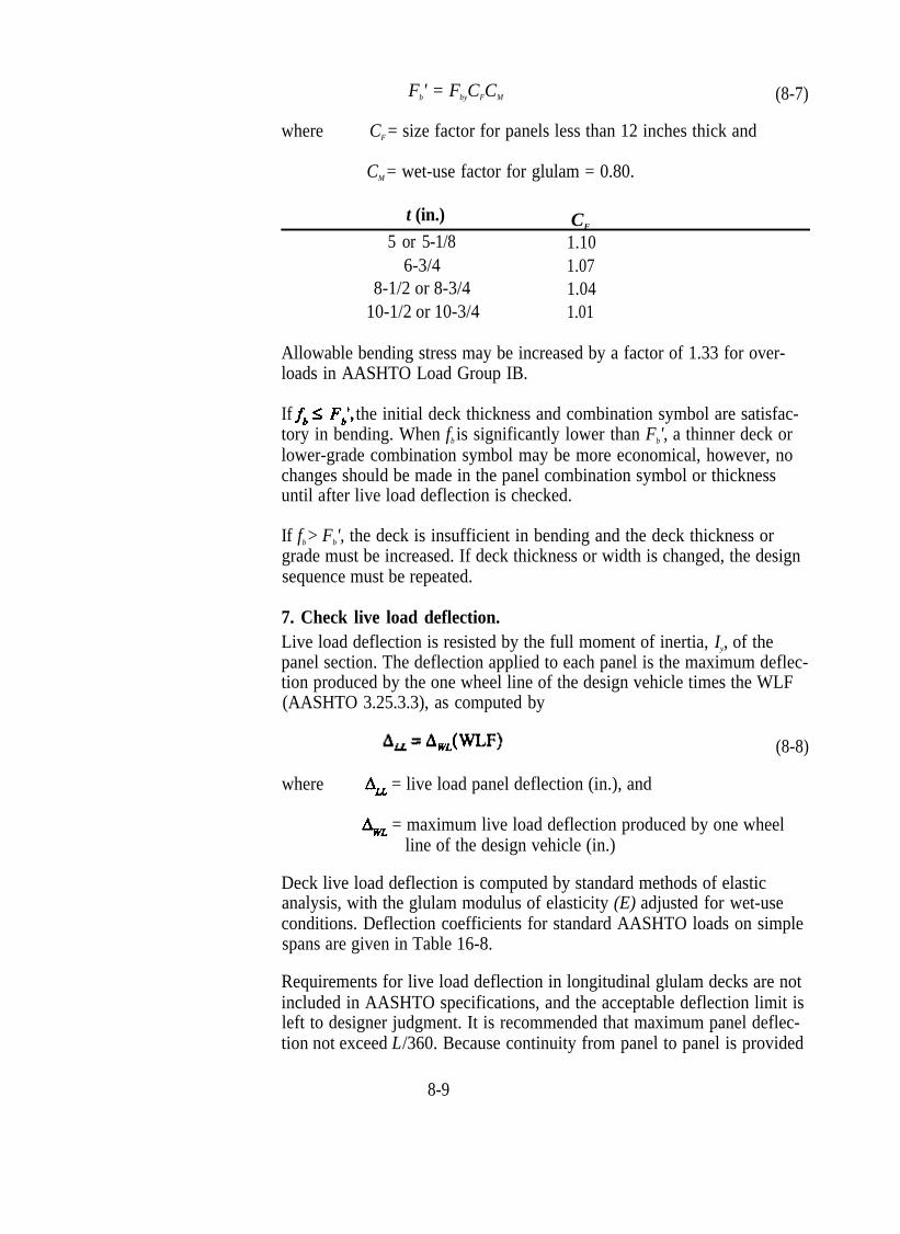
Fb' = FbyCFCM (8-7)
where CF = size factor for panels less than 12 inches thick and
CM = wet-use factor for glulam = 0.80.
t (in.) CF
5 or 5-1/8 1.10 6-3/4 1.07
8-1/2 or 8-3/4 1.04 10-1/2 or 10-3/4 1.01
Allowable bending stress may be increased by a factor of 1.33 for overloads in AASHTO Load Group IB.
If the initial deck thickness and combination symbol are satisfactory in bending. When fb is significantly lower than Fb', a thinner deck or lower-grade combination symbol may be more economical, however, no changes should be made in the panel combination symbol or thickness until after live load deflection is checked.
If fb > Fb', the deck is insufficient in bending and the deck thickness or grade must be increased. If deck thickness or width is changed, the design sequence must be repeated.
7. Check live load deflection.Live load deflection is resisted by the full moment of inertia, Iy, of the panel section. The deflection applied to each panel is the maximum deflection produced by the one wheel line of the design vehicle times the WLF (AASHTO 3.25.3.3), as computed by
(8-8)
where = live load panel deflection (in.), and
= maximum live load deflection produced by one wheel line of the design vehicle (in.)
Deck live load deflection is computed by standard methods of elastic analysis, with the glulam modulus of elasticity (E) adjusted for wet-use conditions. Deflection coefficients for standard AASHTO loads on simple spans are given in Table 16-8.
Requirements for live load deflection in longitudinal glulam decks are not included in AASHTO specifications, and the acceptable deflection limit is left to designer judgment. It is recommended that maximum panel deflection not exceed L/360. Because continuity from panel to panel is provided
8-9
only at stiffener-beam locations, relative panel displacements do occur at locations between these beams. At this time, there is no accurate method for predicting the interpanel displacements between stiffener beams; however, with a maximum panel live load deflection of L/360, ISU studies indicate that the interpanel displacement will not exceed approximately 0.10 inch in most applications (see stiffener-beam design later in thissection). As discussed in Chapter 7, the 0.10-inch limit on relative panel displacement is considered the maximum allowable for acceptable asphalt wearing surface performance. A further reduction in deflection is desirable to reduce the potential for minor asphalt cracks at the panel joints, or when the bridge includes a pedestrian walkway.
8. Check horizontal shear.Horizontal shear is normally not a controlling factor in longitudinal deck design because of the relatively large panel area. It is checked based on the magnitude of the maximum vertical shear occurring at the same locations used for beams (Chapters 5 and 7). Dead load vertical shear is computed at a distance from the support equal to the deck thickness, t, neglecting all loads within the distance t from the supports, using
(8-9)
where VDL = dead load vertical shear at a distance t from the support (lb), and
wDL = uniform panel dead load (lb/ft).
Live load vertical shear is based on the maximum vertical shear occurring at a distance from the support equal to three times the deck thickness (3t) or the span quarter point (L/4), whichever is less. The live load shear applied to each panel is equal to the maximum shear produced by one wheel line of the design vehicle times the WLF for the panel, as computed by
VLL = VWL (WLF) (8-10)
where VLL = live load vertical shear (lb), and
VWL = maximum vertical shear produced by one wheel line of the design vehicle at the lesser distance of 3t or L/4 from the support (lb).
Horizontal shear stress is assumed to be resisted by the total area of the panel cross section. Applied stress must not be greater than the allowable shear stress for the deck combination symbol, as given by
8-10

(8-11)
where
CM = wet-use factor for shear = 0.875.
When f > F ' the only options are to increase the deck thickness or panelv v
width. In both cases the design procedure must be repeated.
9. Determine stiffener spacing and configuration.Transverse stiffener beams are placed across the deck width to distribute loads and deflections among the individual panels (Figure 8-4). As previously discussed, current design criteria for stiffener beams are empirical and are based on analytical and experimental data collected during the ISU studies. A more formal design procedure is currently being developed. In practice, stiffener beams are often used for guardrail post attachment, and therefore, stiffener spacing, strength, and connections may be dictated by more restrictive railing requirements (Chapter 10).
Figure 8-4. - Transverse glulam stiffener beam attached to the underside of a longitudinal glulam deck bridge (photo courtesy of Dave Nordenson, USDA Forest Service).
Stiffener beams typically consist of horizontally laminated glulam beams or shallow steel shapes (Figure 8-5). AASHTO specifications require that a stiffener beam be placed at midspan for all deck spans, and at intermediate spacings not to exceed 10 feet (AASHTO 3.25.3.4). A more restrictive
8-11

intermediate stiffener-beam spacing of 8 feet is recommended by the AITC, which will be used in this chapter.4 Stiffener design consists of sizing the beam so that the stiffness factor, E'I, of the member is not less than 80,000 k-in2; however, this is an approximate value that should not be significantly exceeded. Experimental and analytical tests at ISU have shown that the connection may be overstressed if the stiffness factor is very large, on the order of twice the minimum value. Load distribution between panels is more effectively improved by decreasing stiffener beam spacing, rather than by increasing the beam size substantially above the required minimum.
Figure 8-5. - Types of transverse stiffener-beam configurations for longitudinal glulam deck panels.
Connections between the stiffener beam and the deck panels are placed approximately 6 inches from each panel edge (Figure 8-6). The type of connection depends on the stiffener-beam material and configuration. Through-bolting is used for glulam beams and steel channels. Deck brackets or steel plates are also used for glulam beams, and C-clips are used for
8-12

steel I-beams. A minimum bolt diameter of 3/4 inch is recommended for single through-bolt connections while a minimum 5/8-inch diameter bolt is used for bracket connections. The type of connection is left to designer judgment since all connector types shown in Figure 8-5 were modeled in the ISU study. However, experimental results at ISU indicate that the through-bolt type connections provide more favorable load distribution in the panels and reduce the potential for localized stress conditions in the region of the connection to the stiffener beams. They are also more effective in reducing interpanel displacements that occur between stiffener-beam locations.
Figure 8-6. - Stiffener-beam attachment for longitudinal glulam decks.
10. Determine bearing configuration and check bearing stress.Bearings are designed to resist the vertical and lateral forces in the same manner previously discussed for glulam beams. For longitudinal deck bridges however, the required bearing length is normally controlled by considerations for bearing configuration, rather than stress in compression perpendicular to grain. From a practical standpoint, a bearing length of 10 to 12 inches is recommended for stability and deck attachment. Because of the long, continuous width associated with deck bridges, bearing attachments are normally made through the deck to the supporting cap or sill, or from the deck underside. For short-span crossings, a side attachment using steel angles may also be feasible. Two common configurations are shown in Figure 8-7.
8-13
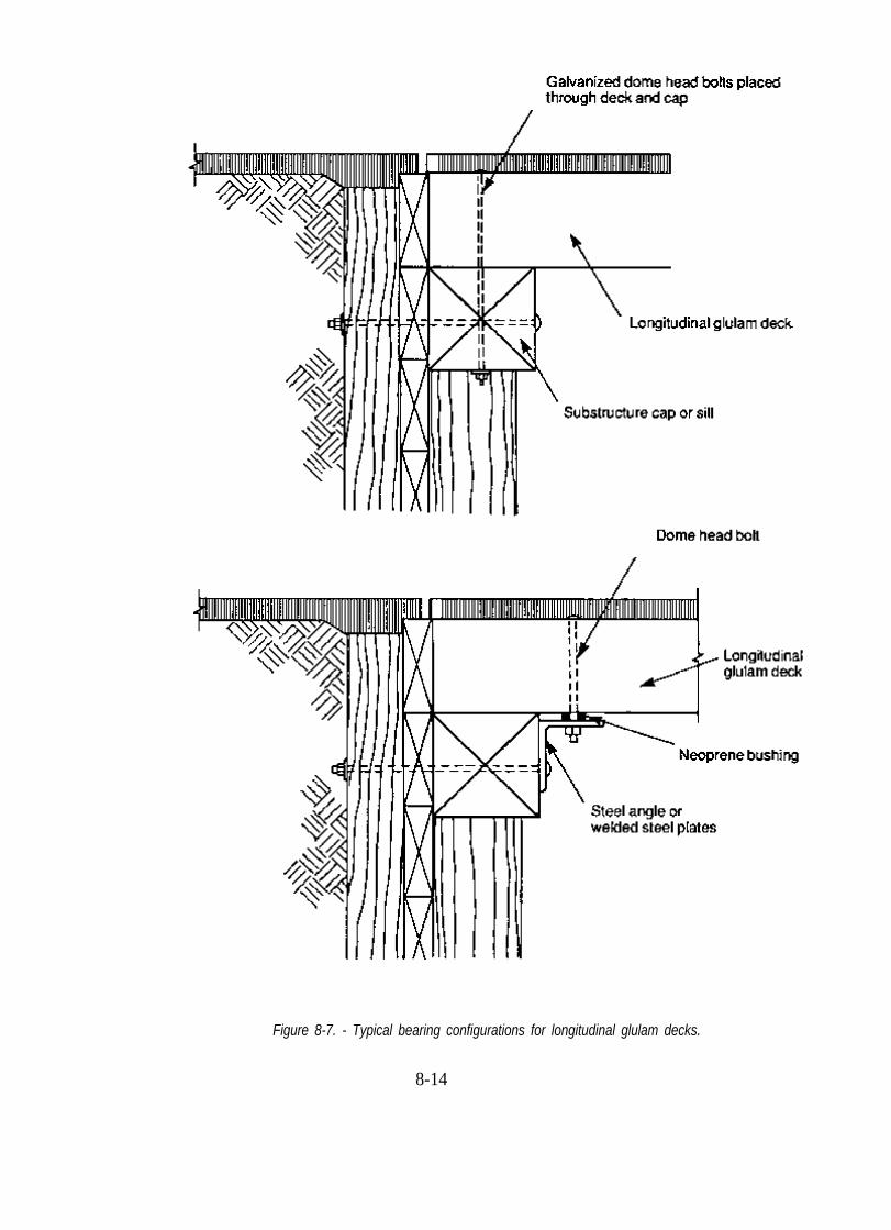
Figure 8-7. - Typical bearing configurations for longitudinal glulam decks.
8-14
Based on the bearing configuration, dead load reactions are computed by conventional methods using the unit dead load of the panel. Live load reactions for single- and multiple-lane bridges are based on the following WLF for reactions (AASHTO 3.25.3.2):
but not less than 1.0 (8-12)
The live load reaction distributed to each panel is the maximum reaction of the design vehicle times the WLF given by Equation 8-12:
RLL = RWL (WLF) (8-13)
where RLL = live load reaction distributed to each deck panel (lb), and
RWL = maximum reaction produced by one wheel line of the design vehicle (lb).
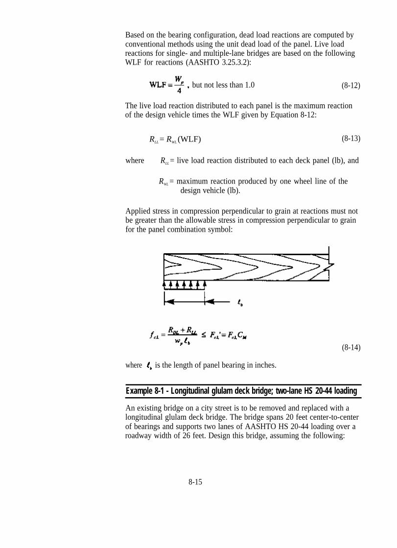
Applied stress in compression perpendicular to grain at reactions must not be greater than the allowable stress in compression perpendicular to grain for the panel combination symbol:
(8-14)
where is the length of panel bearing in inches.
Example 8-1 - Longitudinal glulam deck bridge; two-lane HS 20-44 loading
An existing bridge on a city street is to be removed and replaced with a longitudinal glulam deck bridge. The bridge spans 20 feet center-to-center of bearings and supports two lanes of AASHTO HS 20-44 loading over a roadway width of 26 feet. Design this bridge, assuming the following:
8-15

1. Vehicular railing with a dead load of 55 lb/ft per side is attached to transverse stiffener beams.
2. The rail face extends inward approximately 6 inches from the outside deck edge.
3. The deck will be paved with 3 inches of asphalt pavement.
4. Live load deflection must be limited to L/400.
5. Glulam is visually graded western species.
Solution Define Deck Geometric Requirements and Design Loads With a roadway width of 28 feet, and railing that projects 6 inches inward from each deck edge, a bridge width of 29 feet is required. Design loading will be one HS 20-44 wheel line in AASHTO Load Group I.
Estimate Panel Thickness and Width and Compute Section Properties An initial panel thickness of 10-3/4 inches is selected from Table 8-1. Panel width must be 42 to 54 inches in 1-1/2 inch increments (lamination thickness). The selected configuration will be two outside panels, 51 inches wide, and five interior panels, 49-1/2 inches wide, for a total deck width of 29 feet 1-1/2 inches:
Section properties are computed for the smaller 49.5-inch panel width:
t = 10.75 in.
w = 49.5 in.p
A = t(wp) = 10.75(49.5) = 532.13 in2
8-16

Compute Panel Dead Load From Table 8-2, the dead load of the 49.5inch wide panel with a 3-inch asphalt wearing surface is 339.5 lb/ft. Railing dead load is distributed equally over the deck width. For a total railing load of 2(55) = 110 lb/ft, the load supported by each panel is
An additional estimated dead load of 8 lb/ft will also be applied to each panel for the stiffener beams and associated attachment hardware.
w D L /panel = 339.5 + 15.7 + 8 = 363.2 lb/ft
Determine Wheel Load Fraction for Live Load Distribution By Equation 8-5 for a two-lane bridge,
Therefore, WLF = 0.93WL/panel.
Determine Dead Load and Live Load Moment Dead load moment is computed by assuming each panel is a simply supported beam:
Live load moment is the product of the WLF and the moment produced by one wheel line of the design vehicle. From Table 16-8, the maximum moment from one wheel line of HS 20-44 loading is 80,000 ft-lb:
MLL = 0.93 WL/panel(80,000 ft-lb) = 74,400 ft-lb
M = MDL + MLL = 18,160 + 74,400 = 92,560 ft-lb
8-17

Compute Bending Stress and Select a Deck Combination Symbol
f
F
F
From AITC 117-Design, combination symbol No. 2 is selected with the following tabulated values:
by = 1,800 lb/in2 CM = 0.80
vy = 145 lb/in2 CM = 0.875
= 560 lb/in2 CM = 0.53
E = 1,700,000 lb/in2 CM = 0.833
By Equation 8-7,
Fb' = FbyCFCM = 1,800(1.01)(0.80) = 1,454 lb/in2
b = 1,165 lb/in2 < Fb' = 1,454 lb/in2 so the combination symbol is satisfactory for bending. The combination symbol could be reduced to No. 1 (Fby = 1,450 lb/in2) and still be acceptable in bending; however, it is anticipated that deflection criteria will not be met at the lower E value of 1,500,000 lb/in2. Live load deflection will be checked before changing the combination symbol.
Check Live Load Deflection The deflection coefficient for one wheel line of HS 20-44 loading on a 20-foot span is obtained from Table 16-8:
E' = ECM = 1,700,000(0.833) = 1,416,100 lb/in2
Deck deflection is computed by Equation 8-8:
Live load deflection equals the maximum allowable deflection of L/400. The combination symbol No. 2 panel is retained since any reduction in E will result in excessive deflection.
8-18

tCheck Horizontal Shear Dead load vertical shear is computed at a distance from the support by Equation 8-9:
Live load vertical shear is computed at the lesser distance of 3t or L/4 from the support:
Maximum vertical shear 2.69 feet from the support is computed for one HS 20-44 wheel line:
By Equation 8-10,
Stress in horizontal shear is computed by Equation 8-11:
F ' = F CM = 145 lb/in2(0.875) = 127 lb/in2
v vy
F ' = 127 lb/in2 > f = 53 lb/in2, so shear is satisfactory.v v
Determine Stiffener Spacing and Configuration Maximum spacing for stiffener beams is 8 feet. For this bridge, stiffener beams will be placed at the span third points for a spacing of 6 feet 8 inches:
8-19

The size and stiffness of the stiffener beam must be sufficient to provide a minimum EI value of 80,000 k-in2. Selecting a combination symbol No. 2 glulam stiffener, 6-3/4 inches wide and 4-1/2 inches deep (dry-use conditions may be used for glulam stiffener beams if they are protected by a watertight deck):
E' = ECM = 1,700,000(1.0) = 1,700,000 lb/in2
87,142 k-in2 > 80,000 k-in2, so 6-3/4 by 4-1/2-inch stiffener beams are satisfactory. The beams will be attached to the deck with 3/4-inch-diameter bolts located 6 inches from the panel edge (Figure 8-6).
Checking the stiffener beam dead load,
8-20

4.4 lb/ft is less than the 8 lb/ft assumed, but revision of panel dead load isnot required or warranted.
Determine Bearing Configuration and Check Bearing Stress The length of bearing required for longitudinal glulam deck bridges is generally dictated by requirements for deck attachment to the substructure. In this case, it is assumed that attachment will be by through bolting to a12-inch by 12-inch sill. For a bearing length, of 12 inches:
Dead load reactions are determined by assuming the panel acts as a simple beam between supports. For an out-out panel length of 21 feet,
Live load reactions are computed by multiplying the maximum reaction for one wheel line times the wheel load fraction for reactions (Equation 8-12):
R
From Table 16-8, the maximum reaction for one wheel line of an HS 20-44 vehicle is 20,800 pounds. By Equation 8-13,
L L = R W L(WLF) = (20,800 lb)(1.03) = 21,424 lb
For a length of bearing of 12 inches,
= 297 lb/in2, so a bearing length of 12 inches is satisfactory. The out-to-out length of the panels will be 21 feet.
8-21

Summary The bridge will consist of seven 10-3/4-inch thick glulam panels, 21 feet long, manufactured to AITC 117--Design combination symbol No. 2. The five interior panels are 49-1/2 inches wide and the two outside panels are 51 inches wide. Stiffener beams are 6-3/4-inch by 4-1/2-inch combination symbol No. 2 glulam, placed at the span third points. Stresses and deflection are as follows:
Example 8-2- Longitudinal glulam deck bridge; single-lane with overload
A longitudinal glulam deck bridge with a 14-foot roadway width is to be constructed on a forest road. The bridge will span 15 feet center to center of bearings and support AASHTO HS 20-44 loading with an occasional U80 overload. Design this bridge, assuming the following:
1. Rough-sawn 12-inch by 12-inch curbs are provided along the roadway edges.
2. The deck will be provided with a 4-inch full-sawn lumber wearing surface.
3. Live load deflection for HS 20-44 loads must be limited to L/360.
4. Glulam is visually graded Southern Pine.
Solution Define Deck Geometric Requirements and Design Loads For a roadway width of 14 feet with 12-inch curbs, an out-to-out bridge width of 16 feet is required. Design loading will be an HS 20-44 wheel line in AASHTO Load Group I and a U80 wheel line in AASHTO Load Group IB (33 percent stress increase permitted for occasional overloads).
8-22

Estimate Panel Thickness and Width and Compute Section Properties An initial panel thickness of 8-1/2 inches is estimated from Table 8-1. Panel width will be 48-1/8 inches, rounded to 48 inches for design calculations:
Section properties are as follows:
t = 8.5 in.
w = 48 in.p
A = t(wp ) = 8.5(48) = 408 in2
Compute Panel Dead Load For an 8-1/2-inch deck and 4-inch lumber wearing surface, dead load is computed over the 48-inch panel width:
Curb dead load is assumed to be distributed equally across the deck width. For a total curb load of 2(50 lb/ft) = 100 lb/ft, the load supported by each panel is
With one stiffener beam on a 15 foot span, the dead load of the stiffener beam and attachment hardware will be negligible.
Total wDL per panel = 208.3 + 25 = 233.3 lb/ft.
8-23

Determine Wheel Load Fraction for Live Load Distribution By Equation 8-4 for a one-lane bridge,
WLF = 0.84WL/panel will be used.
Determine Dead Load and Live Load Moment
From Table 16-8 for a 15-foot span, the maximum moment for one wheel line is 60,000 ft-lb for HS 20-44 loading and 100,250 ft-lb for U80 loading.
HS 20-44 MLL = (0.84WL/panel)(60,000) = 50,400 ft-lb
U80 MLL = (0.84WL/panel)(100,250) = 84,210 ft-lb
Compute Bending Stress and Select a Deck Combination Symbol The deck will be designed for the U80 load, then checked for the HS 20-44 load.
M = MDL + U80 MLL = 6,562 + 84,210 = 90,772 ft-lb
F
F
From AITC 117-Design, combination symbol No. 48 is selected with the following tabulated values:
by = 2,000 lb/in2 CM = 0.80
vy = 175 lb/in2 CM = 0.875
= 650 lb/in2 CM = 0.53
E = 1,700,000 lb/in2 CM = 0.833
8-24

Allowable bending stress is computed by Equation 8-7 with a 33-percent increase for group IB loading:
Fb' = 2,213 lb/in2 > fb = 1,885 lb/in2, so the combination symbol is satisfactory in bending for U80 loading.
Check HS 20-44 loading:
M = MDL + MLL = 6,562 + 50,400 = 56,962 ft-lb
Fb' = FbyCFCM = 2,000(1.04)(0.80) = 1,664 lb/in2
Fb' = 1,664 lb/in2 > fb = 1,183 lb/in2, so HS 20-44 loading is also satisfactory.
The combination symbol and deck thickness are acceptable in bending, but the applied stress is considerably lower than the allowable stress. The panel combination symbol could be lowered to a No. 47 (Fb = 1,750 lb/in2), but the E value would be reduced to 1,400,000 lb/in2. Deflection will be checked before any changes are made.
Check Live Load Deflection The deflection coefficient for one wheel line of HS 20-44 loading on a 15-foot span is obtained from Table 16-8:
E' = ECM = 1,700,000(0.833) = 1,416,100 lb/in2
Deck deflection is computed by Equation 8-8:
(WLF) = (0.56 in.)(0.84) = 0.47 in.= L/383
L/383 < L/360, so the deck deflection is acceptable with E = 1,700,000 lb/in2.
For a panel combination symbol No. 47:
E' = ECM = 1,400,000(0.833) = 1,166,200 lb/in2
8-25

The deck deflection for combination symbol No. 47 exceeds the allowable. Combination symbol No. 48 will be retained.
Check Horizontal Shear Dead load vertical shear is computed at a distance t from the support by Equation 8-9:
Live load vertical shear is computed at the lesser of 3t or L/4 from the support:
For U80 loading,
F ' = 169 lb/in2 > f = 87 lb/in2, so shear is satisfactory for the U80.v v
8-26
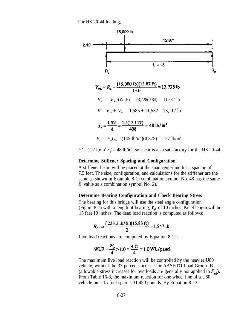
For HS 20-44 loading,
V LL = V W L (WLF) = 13,728(0.84) = 11,532 lb
V = VDL + VLL = 1,585 + 11,532 = 13,117 lb
F ' = F CM = (145 lb/in2)(0.875) = 127 lb/in2
v vy
F ' = 127 lb/in2 > f = 48 lb/in2, so shear is also satisfactory for the HS 20-44.v v
Determine Stiffener Spacing and Configuration A stiffener beam will be placed at the span centerline for a spacing of 7.5 feet. The size, configuration, and calculations for the stiffener are thesame as shown in Example 8-1 (combination symbol No. 48 has the same E' value as a combination symbol No. 2).
Determine Bearing Configuration and Check Bearing Stress The bearing for this bridge will use the steel angle configuration
15 feet 10 inches. The dead load reaction is computed as follows:(Figure 8-7) with a length of bearing, of 10 inches. Panel length will be
Live load reactions are computed by Equation 8-12:
The maximum live load reaction will be controlled by the heavier U80 vehicle, without the 33-percent increase for AASHTO Load Group IB (allowable stress increases for overloads are generally not applied to From Table 16-8, the maximum reaction for one wheel line of a U80 vehicle on a 15-foot span is 31,450 pounds. By Equation 8-13,
8-27

Summary The bridge will consist of four 8-1/2-inch-thick glulam panels, 48-1/8 inches wide, and 15 feet 10 inches long, manufactured to AITC 117--Design combination symbol No. 48. A 6-3/4-inch by 4-1/2-inch combination symbol No. 48 stiffener beam will be placed at the span center. Stresses and deflection are as follows:
HS 20-44 loading U80 overload
8.4 LONGITUDINAL NAIL-LAMINATED LUMBER DECK BRIDGES
Longitudinal nail-laminated deck bridges consist of a series of lumber laminations that are placed on edge and nailed together on their wide faces. They may be constructed either as continuous decks or as panelized decks (Figure 8-8). In continuous decks, each lamination is nailed to the adjacent lamination, making the deck continuous across the bridge width. For panelized decks, laminations are prefabricated into a series of panels that are placed longitudinally between supports and interconnected with transverse stiffener beams. Provisions for panelized decks without distributor beams are also contained in AASHTO, but such decks are not commonly used and are not included in this chapter. Laminations for both continuous and panelized configurations must be one piece over the span length (no butt joints). The bridge clear span is therefore limited by the available length of lumber. Longer crossings are made with a series of simple spans with joints between successive spans over intermediate supports (Figure 8-9).
8-28

Figure 8-8. - Longitudinal nail-laminated lumber decks are constructed as continuous decks and as panelized decks. (A) In continuous decks, laminations are progressively nailed to adjacent laminations to form a continuous deck across the structure width. (B) For panelized decks, lumber is nail-laminated into panels that are interconnected with transverse stiffener beam(s).
Figure 8-9. - Multiple-span longitudinal nail-laminated lumber deck bridge consisting of a series of simple spans (photo courtesy of Wheeler Consolidated, Inc.).
8-29

CONTINUOUS NAILLAMINATED LUMBER BRIDGES
Longitudinal nail-laminated decks are constructed from lumber laminations that are 2 to 4 inches thick, and 5 inches or wider, in the Joist and Plank size classification.11,12 Both continuous and panelized configurations can be constructed from any lumber size provided it is a minimum of 6 inches in nominal depth (AASHTO 3.25.2.2). From a practical standpoint, however, continuous decks are normally constructed of 2-inch nominal material that is 6 to 12 inches wide to facilitate field nailing and handling. Panelized systems commonly use 4-inch nominal material that is 10 to 16 inches wide, which is more economical and practical for shop fabrication.
Continuous nail-laminated lumber bridges are practical for simple spans up to approximately 19 feet for HS 20-44 and H 20-44 loads and 21 feet for HS 15-44 and H 15-44 loads. Load distribution and continuity across the bridge are provided by the nails that are placed through two and one-half laminations, in the same pattern used for transverse nail-laminated decks (Figure 8-10). Transverse stiffener beams are not required. The performance of longitudinal nail-laminated bridges is similar in many respects to transverse nail-laminated decks and depends primarily on the effectiveness of the nails in transferring loads between adjacent laminations. Field experience has shown that many nail-laminated decks demonstrate a tendency to loosen or delaminate from cyclic loading and moisture content changes in the laminations. This subsequently leads to reduced load distribution and deterioration of asphalt wearing surfaces. In longitudinal deck bridges, the potential for delamination is normally higher than for transverse configurations because the deck spans and associated deflections are generally larger. Performance can be improved by limiting live load deflections and using edge-grain lumber for laminations, but these measures may not be totally effective in eliminating deck loosening.
Figure 8-10. - Nailing pattern for continuous longitudinal nail-laminated lumber decks constructed of nominal 2-inch-thick sawn lumber.
8-30

When properly designed, longitudinal nail-laminated deck bridges are generally suitable for low-volume local or rural roads that are not required to carry heavy highway loads. They are not recommended for primary or secondary road systems, or crossings that require an asphalt wearing surface.
Design Procedures Design procedures for longitudinal continuous nail-laminated bridges are similar to those for transverse nail-laminated decks discussed in Chapter 7. For longitudinal decks, however, the span is measured center to center of bearings and different criteria are used for live load distribution (AASHTO 3.25.2). In the longitudinal direction, wheel loads are assumed to act as point loads. In the transverse direction, wheel loads are distributed over a wheel load distribution width, DW, equal to the tire width plus twice the deck thickness (Figure 8-11), as computed by
DW = bt + 2t (8-15)
where
P = wheel load (lb), and
t = deck thickness (in.).
The effective deck section defined by the deck thickness, t, and wheel-load distribution width, DW, is designed as a beam to resist the bending, deflection, shear, and reactions produced by one wheel line of the design
Figure 8-11. - Wheel load distribution width for continuous longitudinal nail-laminated lumber decks.
8-31
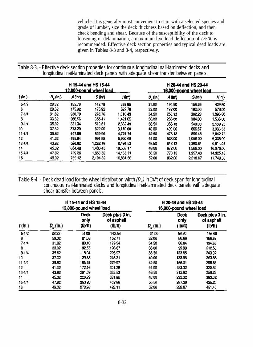
vehicle. It is generally most convenient to start with a selected species and grade of lumber, size the deck thickness based on deflection, and then check bending and shear. Because of the susceptibility of the deck to loosening or delamination, a maximum live load deflection of L/500 is recommended. Effective deck section properties and typical dead loads are given in Tables 8-3 and 8-4, respectively.
Table 8-3. - Effective deck section properties for continuous longitudinal nail-laminated decks and longitudinal nail-laminated deck panels with adequate shear transfer between panels.
Table 8-4. - Deck dead load for the wheel distribution width (DW) in Ib/ft of deck span for longitudinal continuous nail-laminated decks and longitudinal nail-laminated deck panels with adequate shear transfer between panels.
8-32

Example 8.3 - Longitudinal continuous nail-laminated deck; two-lane HS 15-44 loading
A two-lane, 24-foot-wide bridge is to be constructed on a low-volume county road. The bridge spans 19 feet center-to-center of bearings and supports two lanes of AASHTO HS 15-44 loading. Design this bridge as a continuous nail-laminated deck, assuming the following:
1. The deck is covered with a full-width wearing surface of dressed (S4S) 4-inch by 12-inch planks.
2. A modified vehicular railing system will be provided with the rail face extending 8 inches inward from the deck edges. Dead load of the railing is 70 lb/ft per side.
3. Bearing at each end is on a 12-inch by 12-inch timber pile cap.
4. Live load deflection must be limited to L/500.
5. Laminations are dressed 2-inch nominal visually graded Southern Pine.
Solution It is anticipated that the design will be controlled by the maximum live load deflection requirement of L/500. A species of lumber will be selected and the deck initially will be designed based on deflection, then checked for bending and shear.
Define Deck Geometric Requirements and Design Loads For a 24-foot roadway width, and railing that projects 8 inches inward from each deck edge, the total bridge width of 25 feet 4 inches (25.33 feet) is required (203 nominal 1-1/2-inch-thick lumber laminations). Design loading will be one wheel line of an HS 15-44 vehicle in AASHTO Load Group I. Because this bridge is designed for HS 15-44 loads, which are less than H 20-44 loads, the design must also be checked in AASHTO Load Group IA using a 100-percent increase in live load forces and a 50-percent increase in allowable stresses (Chapter 6). This requirement does not apply to live load deflection.
Select a Species and Grade of Lamination From NDS Table 4A, No. 1 visually graded Southern Pine is selected in the J&P size classification from the table “surfaced dry, used at 19%
8-33

maximum m.c.” Per NDS footnotes, stresses for this grade when the moisture content will exceed 19 percent are taken from the table “surfaced green, used any condition”, and further adjustment by CM is not required. Tabulated values are as follows:
Fb = 1,350 lb/in2 (repetitive member uses)
F = 85 lb/in2
v
Determine Deck Thickness Based on Live Load Deflection A deflection of L/500 on a 19-foot span is equivalent to 0.46 inches From Table 16-8, the deflection coefficient for an HS 15-44 vehicle on a 19-foot span is 2.96 x 10⁹ lb-in3. Equating the allowable deflection to the deflection coefficient for one wheel line,
In this case,
E'= ECM = 1,500,000(1.0) = 1,500,000 lb/in2
Rearranging terms, the deflection equation is solved for the required moment of inertia of the effective deck section:
For a minimum I = 4,289.86 in4, an 11-1/4-inch (12-inch nominal) deep lamination is selected from Table 8-3. Effective deck section properties from that table are as follows:
8-34
DW = 39.82 in.
A = 447.98 in2
S = 839.95 in3
I = 4,724.74 in4
The actual live load deflection is computed:
L/543 < L/500, so dressed 2-inch by 12-inch No. 1 Southern Pine laminations are acceptable for live load deflection.
Compute Deck Dead Load The dead load of an 11.25-inch deck and 3.5-inch wearing surface are computed over the effective wheel load distribution width of 39.82 inches:
Dead load of the railing system is uniformly distributed across the deck width:
Total wDL = 203.9 + 18.3 = 222.2 lb/ft
Compute Applied Moments and Bending Stress Dead load moment is computed by assuming the effective deck section is a simply supported beam:
Live load moment is the maximum moment for one wheel line of an HS 15-44 vehicle obtained from Table 16-8:
MLL = 57,000 ft-lb
M = MDL + MLL = 10,027 + 57,000 = 67,027 ft-lb
8-35
Bending stress is computed for the effective deck section:
Fb' = FbCMCF = 1,350(1.0)(1.0) = 1,350 lb/in2
Fb' = 1,350 lb/in2 > fb = 958 lb/in2, so the deck is satisfactory in bending in AASHTO Load Group I. Deflection obviously controls design as indicated by the considerable difference between fb and Fb'.
Bending is next checked for AASHTO Load Group IA loading, using a 100-percent increase in live load moment and a 50-percent increase in allowable bending stress:
M = MDL + 2( M L L) = 10,027 + (2)57,000 = 124,027 ft-lb
Fb' = 1.5(1,350) = 2,025 lb/in2
Fb' = 2,025 lb/in2 > fb = 1,772 lb/in2, so the deck is satisfactory in bending in AASHTO Load Group IA.
Check Horizontal Shear Dead load vertical shear is computed at a distance t from the support, neglecting loads that act within a distance t from the supports:
Live load vertical shear is computed at the lesser of 3t or L/4 from the support:
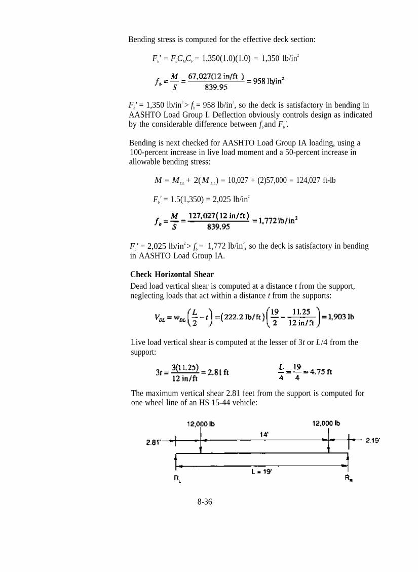
The maximum vertical shear 2.81 feet from the support is computed for one wheel line of an HS 15-44 vehicle:
8-36

V = VDL + VLL = 1,903 + 11,608 = 13,511 lb
F ' = F CM (shear stress modification factor)v v
Using a 2.0 shear stress modification factor (Table 7-17) for nail-laminated lumber treated with oil-type preservatives,
F ' = F CM (2.0) = 85(1.0)(2.0) = 170 lb/in2
v v
F ' = 170 lb/in2 > f = 45 lb/in2, so shear is satisfactory. By examination,v v
shear is also acceptable for AASHTO Load Group IA.
Determine Bearing Configuration and Check Bearing Stress Bearings for this bridge will involve nailing the laminations to a 12-inch by 12-inch pile cap. Dead load reaction is computed as follows, based on a 20-foot bridge length:
The maximum live load reaction for one wheel line of an HS 15-44 is obtained from Table 16-8:
RLL = 15,160 lb
36 lb/in2, so a bearing length of 12 inches is suffi-cient. The out-to-out length of the lumber laminations will be 20 feet.
Determine Nail Size and Pattern Nails must be of sufficient length to penetrate two and one-half laminations. For an actual lamination thickness of 1-1/2 inches, 20d (4-inch long) nails will be used in the pattern shown in Figure 8-10.
8-37

Summary The bridge will consist of 203 nominal 2-inch by 12-inch lumber laminations, 20 feet long. Lumber will be No. 1 or better Southern Pine that is surfaced dry. Stresses and deflection are as follows:
PANELIZED NAILLAMINATED LUMBER BRIDGES
Panelized nail-laminated decks are practical for simple spans up to approximately 34 feet for HS 20-44 and H 20-44 loads and 38 feet for HS 15-44 and H 15-44 loads (Figure 8-12). Load distribution within the panels is provided by spikes placed through the laminations, while load transfer between panels is provided by stiffener beams. Some designs also use a lapped joint between panels to further improve load distribution and continuity between panels (Figure 8-13). Panels for longitudinal nail-laminated bridges are prefabricated before shipment to the construction site and are of approximately equal width, but normally not greater than 7-1/2 feet wide for transportation and erection considerations. Laminations
Figure 8-12. - Panelized longitudinal nail-laminated deck bridges. (A) During construction. (photos courtesy of Wheeler Consolidated, Inc.).
8-38

are spiked together with galvanized 5/16- or 3/8-inch-diameter spikes that are of sufficient length to penetrate four laminations. The placement pattern uses two basic spike patterns involving pairs of adjacent laminations that alternate over the panel width (Figure 8-14). To prevent splitting and reduce potential deterioration, spike lead holes are drilled in the laminations before pressure treatment with preservatives.
Figure 8-12. - Panelized longitudinal nail-laminated deck bridges (continued). (B) Typical multiple-span bridge configuration (photos courtesy of Wheeler Consolidated, Inc.).
Figure 8-13. - Overlap joint configuration for longitudinal nail-laminated lumber deck panels.
8-39

Spike placement in laminations (side view)
Figure 8-14. - Spike placement for longitudinal nail-laminated deck panels constructed of nominal 4-inch-thick lumber laminations.
Because of the larger laminations and increased spike size and length, performance of longitudinal nail-laminated panels is improved over conventional continuous nail-laminated decks. They are commonly used on secondary and local road systems and are capable of supporting repetitive highway loads.
Design Procedures Longitudinal nail-laminated panels are designed using the same basic procedures and live load distribution as continuous longitudinal nail-laminated decks (AASHTO 3.25.2). With panelized decks, however, the live load distribution width cannot exceed the panel width. Transverse stiffener beams are designed for the same requirements used for glulam, with a minimum required stiffness factor, E'I, of 80,000 k-in2. One stiffener is placed at the bridge center, with subsequent stiffeners at intervals not greater than 8 feet. Because of the improved performance of panelized decks over continuous decks, a maximum live load deflection of L/360 is recommended. Effective deck section properties and typical dead loads for panelized decks are given in Tables 8-3 and 8-4.
8-40

Example 8-4 - Longitudinal panelized nail-laminated deck; two-lane, HS 2044 loading
A two-lane, 24-foot-wide bridge is to be constructed on a secondary state road. The bridge spans 31 feet center to center of bearings and supports two lanes of AASHTO HS 20-44 loading. Design this bridge as a panelized nail-laminated deck, assuming the following:
1. The deck is covered with a 3-inch asphalt wearing surface.
2. Vehicular railing is provided with the rail face extending 6 inches inward from the deck edges. Dead load of the railing is 75 lb/ft per side.
3. Bearing at each end will be on a 12-inch by 12-inch timber pile cap.
4. Live load deflection must not exceed L/360.
5. Laminations are 4-inch nominal S4S visually graded Douglas Fir-Larch.
Solution The design sequence for this panelized bridge will follow the same procedures used for the continuous nail-laminated deck in Example 8-3, but will include stiffener beam design similar to that used for longitudinal glulam decks.
Define Deck Geometric Requirements and Design Loads For a 24-foot roadway width, and railing that projects 6 inches inward from each deck edge, the total bridge width of 25 feet is required. Based on an actual lamination thickness of 3-1/2 inches, four panels will be used: two panels of 21 laminations (6 feet 1-1/2 inches wide) and two panels of 22 laminations (6 feet 5 inches wide). The bridge width out-to-out will be 25 feet 1 inch (25.08 feet). Design loading will be one wheel line of an HS 20-44 vehicle in AASHTO Load Group I.
8-41

Select a Species and Grade of Lamination From NDS Table 4A, No. 1 visually graded Douglas Fir-Larch is selected in the J&P size classification. Tabulated values are as follows:
Fb = 1,750 lb/in2 (repetitive member uses) CM = 0.86
Fv = 95 lb/in2 CM = 0.97
= 625 lb/in2 CM = 0.67
E = 1,800,000 lb/in2 CM = 0.97
Determine Deck Thickness Based on Live Load Deflection A deflection of L/360 on a 31-foot span is equivalent to 1.03 inch. From Table 16-8, the deflection coefficient for an HS 20-44 vehicle on a 31-foot span is 2.54 x 10¹⁰ lb-in3:
E' = ECM = 1,800,000(0.97) = 1,746,000 lb/in2
Rearranging terms,
For a minimum I = 14,123.82 in4, a 15-1/4-inch-deep (16-in. nominal) lamination is selected from Table 8-3. Effective deck section properties from that table are as follows:
DW = 50.50 in.
A = 770.13 in2
S = 1,957.40 in3
I = 14,925.18 in4
The actual live load deflection is computed based on the 50.50-inch wheel load distribution width:
L/384 < L/360, so dressed 4-inch by 16-inch No. 1 Douglas Fir-Larch laminations are acceptable for live load deflection.
8-42

Compute Deck Dead Load From Table 8-4, the dead load of a 15.25-inch deck and 3-inch asphalt wearing surface over the wheel distribution width of 50.50 inches is 425.2 lb/ft. An additional dead load of 8 lb/ft will be added for the stiffener beams and attachment hardware. Dead load of the railing system is assumed to be uniformly distributed across the deck width:
Total wDL = 425.2 + 8 + 25.2 = 458.4 lb/ft
Compute Applied Moments and Bending Stress
M
Maximum moment for one wheel line of an HS 20-44 vehicle on a 31-foot span is obtained from Table 16-8:
LL = 148,650 ft-lb
M = MDL + MLL = 55,065 + 148,650 = 203,715 ft-lb
Bending stress is computed for the effective deck section:
Fb' = FbCMCF = 1,750 (0.86)(1.0) = 1,505 lb/in2
Fb' = 1,505 lb/in2 > fb = 1,249 lb/in2, so the deck is satisfactory in bending.
Check Horizontal Shear
Live load vertical shear is computed at the lesser of 3t or L/4 from the support:
The maximum vertical shear 3.81 feet from the support is computed for one HS 20-44 wheel line:
8-43
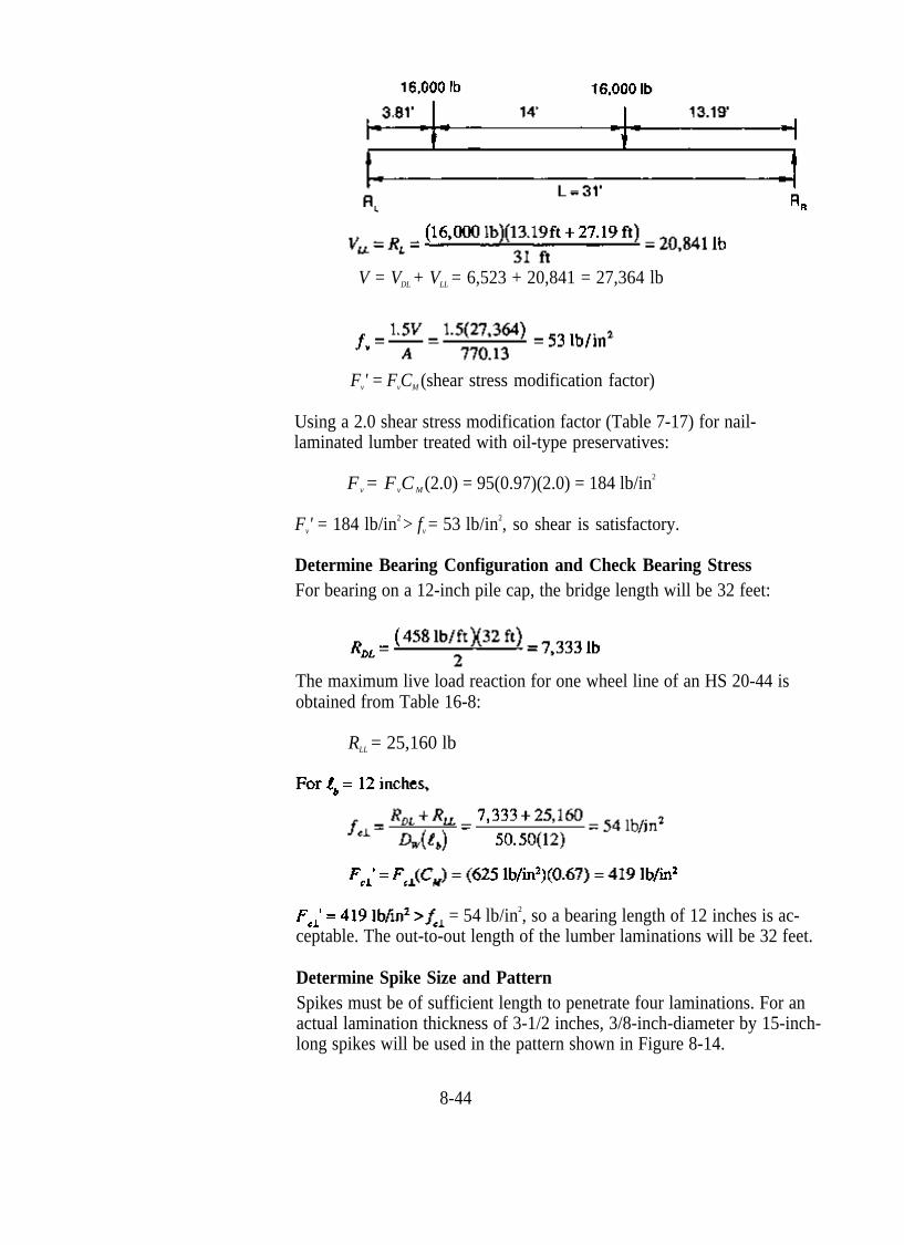
V = VDL + VLL = 6,523 + 20,841 = 27,364 lb
F ' = F CM (shear stress modification factor)v v
Using a 2.0 shear stress modification factor (Table 7-17) for nail-laminated lumber treated with oil-type preservatives:
F = F C M (2.0) = 95(0.97)(2.0) = 184 lb/in2
v v
F ' = 184 lb/in2 > f = 53 lb/in2, so shear is satisfactory.v v
Determine Bearing Configuration and Check Bearing Stress For bearing on a 12-inch pile cap, the bridge length will be 32 feet:
The maximum live load reaction for one wheel line of an HS 20-44 is obtained from Table 16-8:
RLL = 25,160 lb
= 54 lb/in2, so a bearing length of 12 inches is ac-ceptable. The out-to-out length of the lumber laminations will be 32 feet.
Determine Spike Size and Pattern Spikes must be of sufficient length to penetrate four laminations. For an actual lamination thickness of 3-1/2 inches, 3/8-inch-diameter by 15-inch-long spikes will be used in the pattern shown in Figure 8-14.
8-44

Determine Stiffener Spacing and Configuration Design requirements for stiffener beams on panelized nail-laminated decks are the same as those for longitudinal glulam decks. For this bridge, stiffener beams will be placed at the span quarter points for a spacing of 7.75 feet:
The size and stiffness of an individual stiffener beam must be sufficient to provide a minimum E'I value of 80,000 k-in2. A glulam stiffener will be used because of the improved dimensional stability of glulam compared to sawn timber. Selecting a combination symbol No. 2 stiffener, 5-1/8 inches wide and 6 inches deep:
E' = ECM = 1,700,000(0.833) = 1,416,100 lb/in2
130,635 k-in2 > 80,000 k-in2, so 5-1/8-inch by 6-inch stiffener beams are satisfactory. Stiffener attachment will be with 3/4-inch-diameter bolts as described in Example 8-1.
Checking the stiffener beam dead load per panel,
6.5 lb/ft is less than the 8 lb/ft assumed, so no dead load revision isrequired.
Summary The bridge will consist of four nail-laminated panels constructed of S4S 4-inch by 16-inch lumber, 32 feet long. The two outside panels will be 6 feet 5 inches wide (22 laminations) and the two interior panels will be 6 feet 1-1/2 inches wide (21 laminations). Lumber will be No. 1 or better
8-45

Douglas Fir-Larch in the J&P size classification. Stresses and deflection are as follows:
fb = 1,249 lb/in2
F ' = 1,505 lb/in2
b
= 0.97 in. = L /384
f = 53 lb/in2
v
F ' = 184 lb/in2
v
= 54 lb/in2
= 419 lb/in2
Stiffener beams will consist of three 5-1/8-inch-wide by 6-inch-deep by 25-feet-1-inch-long glulam beams, manufactured to combination symbol No. 2.
8.5 LONGITUDINAL DECKS ON TRANSVERSE FLOORBEAMS
One of the primary applications of longitudinal timber decks has been on transverse floorbeams. Floorbeams are transverse beams that either support a longitudinal deck directly or support longitudinal stringers, which in turn support a transverse deck (Figure 8-15). They are used primarily in truss and arch superstructures, and on beam superstructures where the beam spacing exceeds the economical span for transverse deck configurations. Longitudinal decks with floorbeams are used for new structures, but they have also demonstrated distinct advantages in the rehabilitation of existing structures, predominantly as a replacement for deteriorated concrete decks. Not only can a concrete deck be economically replaced with timber, but the lighter dead loads and improved live load distribution frequently result in an increased capacity for existing structures.9 In many cases, dead load is further reduced when existing stringers are removed and the timber replacement deck is placed directly on the floorbeams (Figure 8-16). Longitudinal timber decks have been used in many cases to restore structurally deficient bridges to full capacity for modem highway loads (Chapter 15).
FLOORBEAM DESIGN Floorbeams are designed to support the deck dead load and vehicle live loads over the tributary deck span. Their design follows the same basic beam design procedures discussed in Chapters 5 and 7; however, AASHTO gives specific live load distribution criteria for transverse floorbeams (AASHTO 3.23.3). In both the transverse and longitudinal directions, no wheel load distribution is assumed and the wheel loads are
8-46

Longitudinal deck supported on transverse floorbeams
Transverse deck supported on longitudinal stringers, supported on transverse floorbeams
Figure 8-15. - Timber bridge floorbeam configurations.
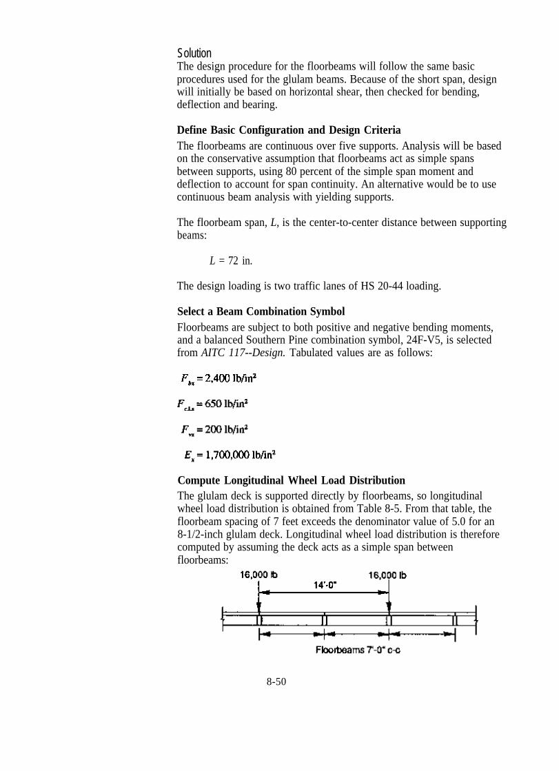
assumed to act as concentrated loads (Figure 8-17). When the deck is supported directly on the floorbeams, the portion of the wheel loads longitudinally distributed to each beam depends on the deck type and the center-to-center floorbeam spacing. For beam spacings of approximately 4-1/2 to 5-1/2 feet, depending on the deck type and thickness, the fraction of the wheel load applied to each floorbeam is determined from empirical equations given in AASHTO (Table 8-5). For greater floorbeam spacings, the load on each beam is the reaction of the wheel loads, assuming the deck acts as a simple span between floorbeams. It should be noted that the AASHTO empirical equations in Table 8-5 are based on the ability of the deck to distribute loads longitudinally among adjacent floorbeams. For floorbeams at bridge ends, longitudinal distribution is limited because there is no adjacent beam on the approach roadway. End floorbeams should therefore be designed for the reaction of the wheel lines, assuming the deck acts as a simple span between beams.
8-47
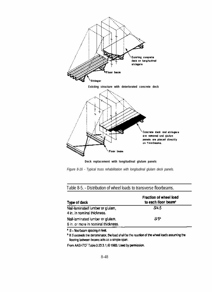
Existing structure with deteriorated concrete deck
Deck replacement with longitudinal glulam panels
Figure 8-16 - Typical truss rehabilitation with longitudinal glulam deck panels.
Table 8-5. - Distribution of wheel loads to transverse floorbeams.
8-48

Figure 8-17. - Wheel load distribution to transverse floorbeams that directly support a longitudinal timber deck.
Example 8-5 - Transverse glulam floorbeam design
A beam bridge carries two lanes of AASHTO HS 20-44 loading on a 26-foot roadway width. The beam system consists of five 10-1/2-inch-wide glulam beams, spaced 6 feet on center. The deck is a series of longitudinal glulam panels that are supported by transverse glulam floorbeams, spaced 7 feet on center. Design the floorbeams for this structure, assuming the following:
1. The deck is 8-1/2 inches thick and is provided with a 3-inch asphalt wearing surface.
2. Floorbeams are visually graded Southern Pine glulam and are provided with continuous lateral support from the deck. Floorbeam attachment to the supporting beams is adequate to prevent sliding or overturning of the floorbeams.
3. The deck is watertight and protects floorbeams from exposure to weathering. With the exception of compression perpendicular to grain, dry condition stresses may be used for design.
4. Floorbeam live load deflection must not exceed L/500.
8-49
Solution The design procedure for the floorbeams will follow the same basic procedures used for the glulam beams. Because of the short span, design will initially be based on horizontal shear, then checked for bending, deflection and bearing.
Define Basic Configuration and Design Criteria The floorbeams are continuous over five supports. Analysis will be based on the conservative assumption that floorbeams act as simple spans between supports, using 80 percent of the simple span moment and deflection to account for span continuity. An alternative would be to use continuous beam analysis with yielding supports.
The floorbeam span, L, is the center-to-center distance between supporting beams:
L = 72 in.
The design loading is two traffic lanes of HS 20-44 loading.
Select a Beam Combination Symbol Floorbeams are subject to both positive and negative bending moments, and a balanced Southern Pine combination symbol, 24F-V5, is selected from AITC 117--Design. Tabulated values are as follows:
Compute Longitudinal Wheel Load Distribution The glulam deck is supported directly by floorbeams, so longitudinal wheel load distribution is obtained from Table 8-5. From that table, the floorbeam spacing of 7 feet exceeds the denominator value of 5.0 for an 8-1/2-inch glulam deck. Longitudinal wheel load distribution is therefore computed by assuming the deck acts as a simple span between floorbeams:
8-50
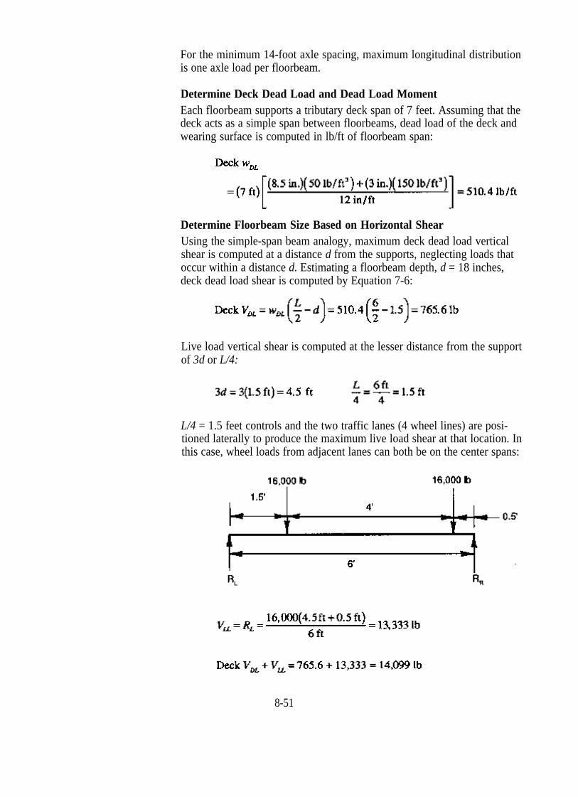
For the minimum 14-foot axle spacing, maximum longitudinal distribution is one axle load per floorbeam.
Determine Deck Dead Load and Dead Load Moment Each floorbeam supports a tributary deck span of 7 feet. Assuming that the deck acts as a simple span between floorbeams, dead load of the deck and wearing surface is computed in lb/ft of floorbeam span:
Determine Floorbeam Size Based on Horizontal Shear Using the simple-span beam analogy, maximum deck dead load vertical shear is computed at a distance d from the supports, neglecting loads that occur within a distance d. Estimating a floorbeam depth, d = 18 inches, deck dead load shear is computed by Equation 7-6:
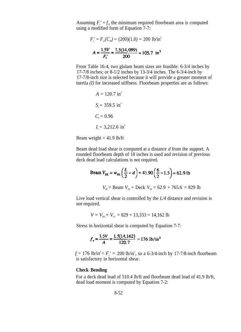
Live load vertical shear is computed at the lesser distance from the support of 3d or L/4:
L/4 = 1.5 feet controls and the two traffic lanes (4 wheel lines) are positioned laterally to produce the maximum live load shear at that location. In this case, wheel loads from adjacent lanes can both be on the center spans:
8-51
Assuming F ' = fv, the minimum required floorbeam area is computedv
using a modified form of Equation 7-7:
F ' = F (CM) = (200)(1.0) = 200 lb/in2
v vx
From Table 16-4, two glulam beam sizes are feasible: 6-3/4 inches by 17-7/8 inches; or 8-1/2 inches by 13-3/4 inches. The 6-3/4-inch by 17-7/8-inch size is selected because it will provide a greater moment of inertia (I) for increased stiffness. Floorbeam properties are as follows:
A = 120.7 in2
S = 359.5 in3
x
CF = 0.96
I = 3,212.6 in4
x
Beam weight = 41.9 lb/ft
Beam dead load shear is computed at a distance d from the support. A rounded floorbeam depth of 18 inches is used and revision of previous deck dead load calculations is not required.
VDL = Beam VDL + Deck VDL = 62.9 + 765.6 = 829 lb
Live load vertical shear is controlled by the L/4 distance and revision is not required.
V = VDL + VLL = 829 + 13,333 = 14,162 lb
Stress in horizontal shear is computed by Equation 7-7:
f = 176 lb/in2 < F ' = 200 lb/in2, so a 6-3/4-inch by 17-7/8-inch floorbeamv v
is satisfactory in horizontal shear.
Check Bending For a deck dead load of 510.4 lb/ft and floorbeam dead load of 41.9 lb/ft, dead load moment is computed by Equation 7-2:
8-52

Live load moment is determined by positioning the wheel loads laterally to produce the maximum moment in the floorbeam. For a 6-foot floorbeam span, maximum moment is produced with one wheel load centered on a span:
Allowable bending stress is computed using the beam size factor, CF
Consideration of lateral stability is not required because the floorbeams are continuously supported by the deck:
fb = 884 lb/in2 is substantially less than Fb'= 2,304 lb/in2, indicating that beam size is controlled by horizontal shear. By examining the various visually graded Southern Pine combination symbols in AITC 117--Design, it is seen that F for most combinations is 200 lb/in2 although Fbxvx
varies from 1,600 lb/in2 to 2,400 lb/in2. In this application, a new balanced combination symbol 16F-V5 is selected with the following section properties:
F = 200 lb/in2
vx
E = 1,400,000 lb/in2
8-53
x
Allowable bending stress is recomputed for the revised combination symbol:
Fb' = (1,600 lb/in2)(0.96) = 1,536 lb/in2 > fb = 884 lb/in2
Check Live Load Deflection Live load deflection is computed with a wheel load centered on a floorbeam span. Using 80 percent of the simple span deflection to account for span continuity,
E' = E (CM) = 1,400,000(1.00) = 1,400,000 lb/in2
x
0.03 in. = L/2,400 < L/500, so live load deflection is acceptable.
Check Bearing Stress Bearing stress between the floorbeam and the longitudinal supporting beam is checked for a bearing area, A, equal to the floorbeam width times beam width, DW :
A = (6.75 in.)(10.50 in.) = 70.88 in2
Dead load and live load reactions are computed by assuming that the deck acts as a simple span between floorbeams. From bending calculations, floorbeams support a dead load of 552.3 lb/ft of deck width. The dead load reaction is computed based on a tributary deck width equal to the spacing of the supporting beams,
RDL = (552.3 lb/ft)(6ft) = 3,314 lb
Maximum live load reaction occurs with one wheel load over the beam,
RLL = 16,000 lb
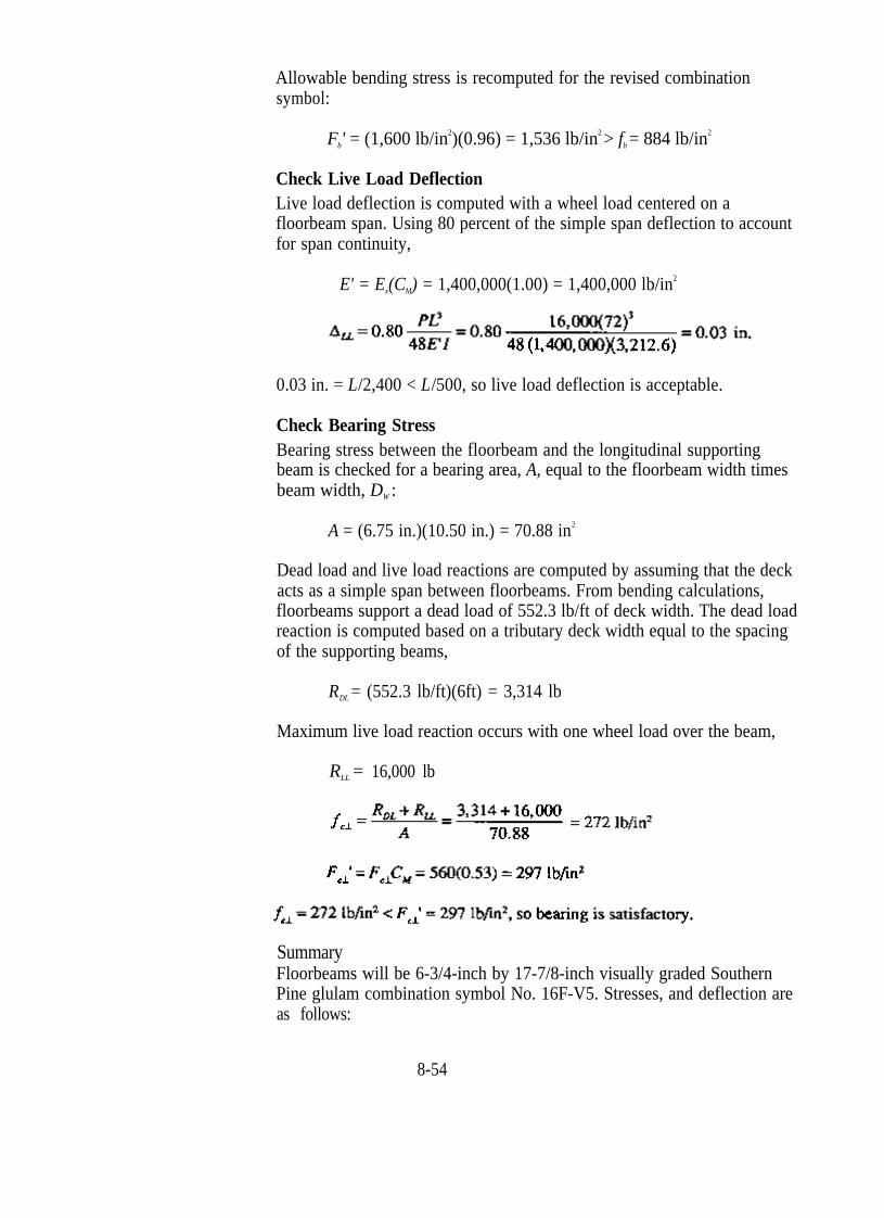
Summary Floorbeams will be 6-3/4-inch by 17-7/8-inch visually graded Southern Pine glulam combination symbol No. 16F-V5. Stresses, and deflection are as follows:
8-54
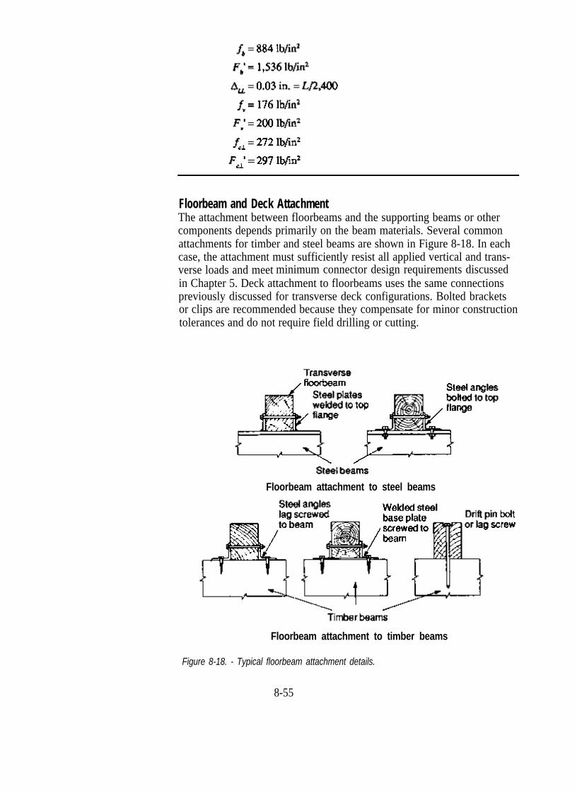
Floorbeam and Deck Attachment The attachment between floorbeams and the supporting beams or other components depends primarily on the beam materials. Several common attachments for timber and steel beams are shown in Figure 8-18. In each case, the attachment must sufficiently resist all applied vertical and transverse loads and meet minimum connector design requirements discussed in Chapter 5. Deck attachment to floorbeams uses the same connections previously discussed for transverse deck configurations. Bolted brackets or clips are recommended because they compensate for minor construction tolerances and do not require field drilling or cutting.
Floorbeam attachment to steel beams
Floorbeam attachment to timber beams
Figure 8-18. - Typical floorbeam attachment details.
8-55

DECK DESIGN The design of glulam or nail-laminated longitudinal decks on transverse floorbeams is basically the same as the design of longitudinal deck bridges. The primary difference is that floorbeam spans are generally less than those typically encountered in superstructure design. Because the longitudinal deck functions specifically as a deck or floor in floorbeam applications, rather than the primary support for the bridge, the design criteria are also slightly different. When used on floorbeams, the deck span, s, is the clear distance between the floorbeams plus one-half the width of one beam, but not greater than the clear span plus the floor thickness (AASHTO 3.25.2.3). In addition, the assumptions used in deck analysis may vary among applications. In continuous multiple-span longitudinal deck bridges, the deck is normally analyzed as a continuous beam. On floorbeams, spans are usually substantially less, and AASHTO permits the deck to be designed as a series of simple spans. If the deck is continuous over more than two spans, the maximum positive moment and deflection from the design truck load are assumed to be 80 percent of those computed for a simple span (AASHTO 3.25.4). This simple span assumption may be adequate for most longitudinal decks on floorbeams, but for long deck spans or unusual configurations the designer should analyze the deck as if it were a continuous member, rather than a series of simple spans.
Longitudinal Glulam Decks Glulam is normally the preferred material for longitudinal decks over floorbeams because of its higher strength, improved performance, and longer panel lengths compared to sawn lumber (Figure 8-19). In longitudinal deck applications, glulam panels may be used with transverse stiffener beams or as noninterconnected panels without stiffener beams. When stiffener beams are used, the deck is designed in the same manner as was the longitudinal deck bridge based on the ISU studies previously discussed. However, for those design criteria to be applicable, a transverse stiffener beam must be provided between floorbeams to provide lateral continuity and load distribution among the panels. Therefore, the glulam panel stiffener-beam configuration is most practical for long deck spans of approximately 8 feet or more.
In addition to longitudinal decks with stiffener beams, a noninterconnected glulam panel configuration is also used on floorbeam spacings of approximately 8 feet or less. Noninterconnected glulam panels function independently, and there is no load distribution among adjacent panels. In the direction of the deck span, wheel loads are assumed to act as point loads. In the transverse direction, the wheel loads are laterally distributed to the panel over a wheel load distribution width, DW, equal to the tire width, bt, plus the deck thickness (Figure 8-20). The deck is then designed as a beam, assuming that the deck section of thickness t and width DW resists the forces produced by one wheel line of the design vehicle. Many of the design limitations and maximum spans for longitudinal noninterconnected
8-56

panels closely parallel those for transverse glulam panels discussed in Chapter 7. Because there is no load sharing among panels, a maximum panel deflection of approximately 0.10 inch is recommended.
Figure 8-19. - Longitudinal glulam deck on transverse glulam floorbeams.
Deck thickness, t
Figure 8-20. - Wheel load distribution width for longitudinal noninterconnected glulam decks.
8-57

Example 8-6 - Longitudinal glulam deck on transverse floorbeams
A steel bridge carries two traffic lanes of AASHTO HS 20-44 loading on a roadway width of 24 feet. Rehabilitation of the structure will involve replacement of the existing concrete deck with a longitudinal glulam deck. The new deck will be placed on 10-inch-wide transverse steel floorbeams that are spaced 6 feet on center. Design a glulam deck for this bridge, assuming the following:
1. The deck will be provided with a 3-inch asphalt wearing surface.
2. The dead load of the railing system is carried by the steel floorbeams.
3. Live load deflection must be limited to 0.10 inch.
4. Glulam deck panels are manufactured from visually graded western species.
Solution For a floorbeam span of 6 feet, noninterconnected glulam deck panels without transverse stiffener beams will be used. The panels will initially be designed for bending, then checked for deflection, shear, and bearing. Although this deck is oriented longitudinally, many of the design aids and equations given in Chapter 7 for transverse noninterconnected decks will also be applicable to this design.
Define Deck Geometric Requirements and Design Loads The deck span, s, is the clear distance between supporting floorbeams plus one-half the width of one beam, but not greater than the clear span plus the deck thickness, t.
8-58
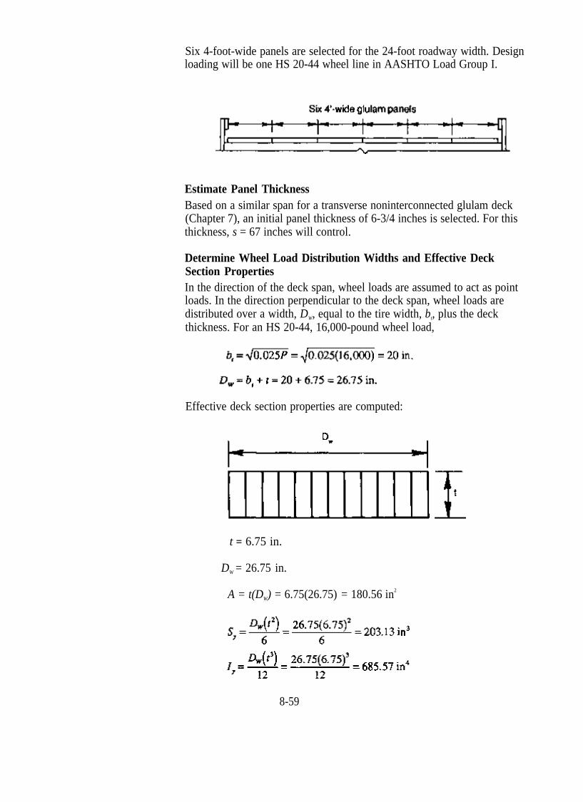
Six 4-foot-wide panels are selected for the 24-foot roadway width. Design loading will be one HS 20-44 wheel line in AASHTO Load Group I.
Estimate Panel Thickness Based on a similar span for a transverse noninterconnected glulam deck (Chapter 7), an initial panel thickness of 6-3/4 inches is selected. For this thickness, s = 67 inches will control.
Determine Wheel Load Distribution Widths and Effective Deck Section Properties In the direction of the deck span, wheel loads are assumed to act as point loads. In the direction perpendicular to the deck span, wheel loads are distributed over a width, DW, equal to the tire width, bt, plus the deck thickness. For an HS 20-44, 16,000-pound wheel load,
Effective deck section properties are computed:
t = 6.75 in.
DW = 26.75 in.
A = t(DW) = 6.75(26.75) = 180.56 in2
8-59

Compute Panel Dead Load and Dead Load Moment For a 6-3/4-inch deck with a 3-inch asphalt wearing surface, dead load is computed for the 26.75-inch distribution width:
Dead load moment is computed by assuming the deck acts as a simple span between floorbeams:
Compute Live Load Moment The maximum live load moment occurs with the 16,000-pound wheel load centered on the deck span:
Compute Bending Stress and Select a Deck Combination Symbol The deck is continuous over more than two spans, so the maximum bending moment is 80 percent of that computed for a simple span to account for span continuity:
M = MDL + MLL = 6,846 + 268,000 = 274,846 in-lb
From AITC 117--Design, combination symbol No. 1 is selected with the following tabulated values:
8-60

Allowable bending stress is computed by Equation 8-7:
Fb' = FbyCFCM = 1,450(1.07)(0.80) = 1,241 lb/in2
Fb' = 1,241 lb/in2 > fb = 1,082 lb/in2, so the combination symbol and deck thickness are satisfactory in bending.
Check Live Load Deflection As with moment, the wheel load is positioned at the span centerline for maximum deflection. Deflection is computed by standard engineering methods using 80 percent of the simple span deflection to account for span continuity:
E' = ECM = 1,500,000(0.833) = 1,249,500 lb/in2
0.09 inch < 0.10 inch, so deck deflection is acceptable.
Check Horizontal Shear Dead load vertical shear is computed by at a distance t from the supports by Equation 8-9:
Live load vertical shear is computed at the lesser distance of 3t or s/4 from the support:
8-61

V = VDL + VLL = 326.4 + 12,000 = 12,326 lb
Fv' = F (CM) = (145 lb/in2)(0.875) = 127 lb/in2
vy
f = 102 lb/in2 < F ' = 127 lb/in2, so shear is satisfactory.v v
Check Bearing Stress Bearing stress between the deck and floorbeam is checked for a bearing area, A, equal to the floorbeam width times the wheel load distribution width, DW:
A = (10 in.)(26.75 in.) = 267.5 in2
Dead load and live load reactions are computed by assuming that the deck acts as a simple span between floorbeams:
R
RDL = s(wDL) = (72 in.)(12.2 lb/in) = 878.4 lb
LL = 16,000 lb
Summary The deck will consist of six 6-3/4-inch glulam panels, 48 inches wide and 68 feet long. The glulam will combination symbol No. 1, manufactured from visually graded western species. Stresses and deflection are as follows:
8-62
Longitudinal Nail-Laminated Lumber Decks Longitudinal nail-laminated decks over floorbeams are designed for the effective span, s, using the same design procedures as longitudinal bridges. The continuous configuration is most practical for spans up to approximately 10 feet where live load deflection can be limited to s/500. For longer spans, the panelized configuration is used with a stiffener beam placed at center span between floorbeams and at maximum intervals of 8 feet for longer spans.
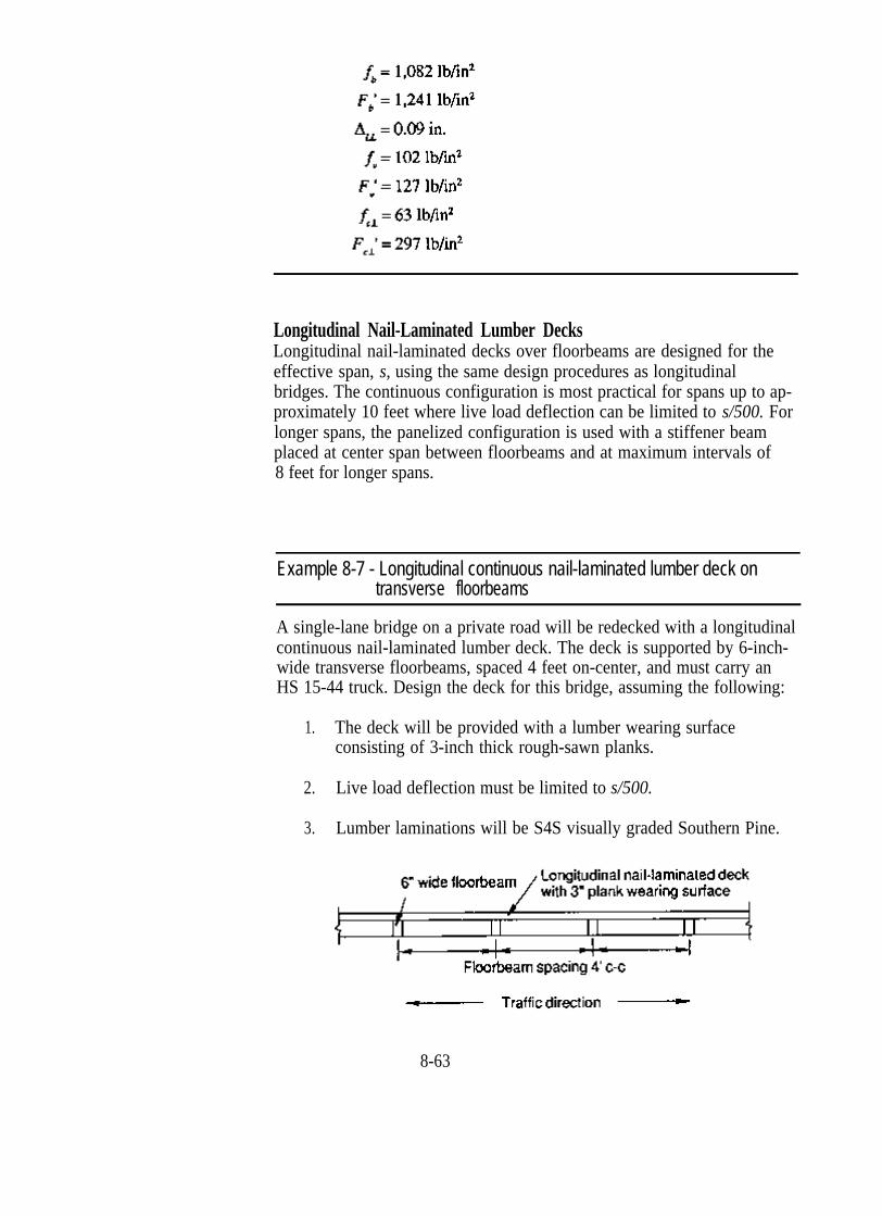
Example 8-7 - Longitudinal continuous nail-laminated lumber deck on transverse floorbeams
A single-lane bridge on a private road will be redecked with a longitudinal continuous nail-laminated lumber deck. The deck is supported by 6-inch-wide transverse floorbeams, spaced 4 feet on-center, and must carry an HS 15-44 truck. Design the deck for this bridge, assuming the following:
1. The deck will be provided with a lumber wearing surface consisting of 3-inch thick rough-sawn planks.
2. Live load deflection must be limited to s/500.
3. Lumber laminations will be S4S visually graded Southern Pine.
8-63
Solution Given the relatively short span, it is anticipated that AASHTO requirements for a minimum nominal deck thickness of 6 inches will control. It is also suspected that horizontal shear will be the controlling stress. The deck initially will be designed for shear, then checked for bending, deflection, and bearing.
Define Deck Geometric Requirements and Design Loads The deck span, s, is the clear distance between supporting floorbeams plus one-half the width of one beam, but not greater than the clear span plus the deck thickness, t.
Clear distance between floorbeams = 48 in. - 6 in. = 42 in.
s = 45 inches will control the effective deck span.
Design loading will be one HS 15-44 wheel load (12,000 pounds) in AASHTO Load Group I.
Select a Species and Grade of Lamination From NDS Table 4A, No. 2 visually graded Southern Pine is selected in the J&P size classification from the table labeled “surfaced dry, used at 19% maximum m.c.” Per NDS footnotes, wet-use values are obtained from the table “surfaced green, used any condition.” Further adjustment by CM is not required.
F b = 1,100 lb/in2 (repetitive member uses)
Estimate Deck Thickness and Compute Section Properties For this short span, the minimum deck thickness of 5-1/2 inches (6 inches nominal) is selected. In the direction perpendicular to the deck span, the wheel load is distributed over a deck width, DW, equal to the tire width plus twice the deck thickness. From Table 8-3,
t = 5.5 in.
DW = 28.32 in.
A = 155.76 in2
8-64

S = 142.78 in3
I = 392.65 in4
Check Horizontal Shear
From Table 8-4, the dead load of the 5-1/2-inch lumber deck and 3-inch plank wearing surface over a distribution width DW = 28.32 inches is 142.6 lb/ft, or 11.9 lb/in. Dead load vertical shear is computed at a distance t from the support by Equation 8-9:
Live load vertical shear is computed at the lesser of 3t or s/4 from the support:
s/4 = 11.25 inches controls:
8-65
v
F ' = F CM (shear stress modification factor)v v
Using a shear stress modification factor of 2.0 for nail-laminated lumber treated with oil-type preservatives (Table 7-17),
F ' = 85(1.0)(2.0) = 170 lb/in2
f = 89 lb/in2 < F ' = 170 lb/in2, so the deck is satisfactory for horizontalv v
shear.
Check Bending Dead load moment is computed by assuming that the effective deck section is a simply supported beam:
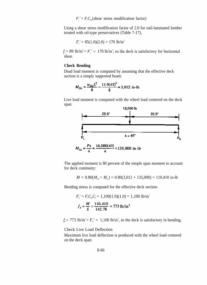
Live load moment is computed with the wheel load centered on the deck span:
The applied moment is 80 percent of the simple span moment to account for deck continuity:
M = 0.80(MDL + MLL) = 0.80(3,012 + 135,000) = 110,410 in-lb
Bending stress is computed for the effective deck section:
Fb' = FbCMCF = 1,100(1.0)(1.0) = 1,100 lb/in2
fb = 773 lb/in2 < Fb' = 1,100 lb/in2, so the deck is satisfactory in bending.
Check Live Load Deflection Maximum live load deflection is produced with the wheel load centered on the deck span:
8-66

E' = ECM = 1,400,000(1.0) = 1,400,000 lb/in2
Using 80 percent of the simple span deflection to account for span continuity,
s/1,500 < s/500, so deflection is acceptable.
Check Bearing Stress Bearing stress between the deck and floorbeam is checked for a bearing area, A, equal to the floorbeam width times the wheel load distribution width, DW:
A = (6 in.)(28.32 in.) = 169.92 in2
Dead load and live load reactions are computed by assuming that the deck acts as a simple span between floor-beams:
R
RDL = (48 in.)(w D L) = (48 in.)( 11.9 lb/in) = 571.2 lb
LL = 12,000 lb
Summary The deck will consist of S4S Southern Pine laminations that are visually graded No. 2 or better. The laminations will be nailed in the pattern shown in Figure 8-10 using 20d nails. Stresses and deflection are as follows:
8-67
8.6 SELECTED REFERENCES
1.
2.
3.
4.
5.
6.
7.
8.
9.
10.
American Association of State Highway and Transportation Officials. 1983. Standard specifications for highway bridges. 13th ed. Washington, DC: American Association of State Highway and Transportation Officials. 394 p. American Association of State Highway and Transportation Officials. 1983. Manual for maintenance inspection of bridges. Washington, DC: American Association of State Highway and Transportation Officials. 50 p. American Institute of Timber Construction. 1987. Design standard specifications for structural glued laminated timber of softwood species. AITC 117-87-Design. Englewood, CO: American Institute of Timber Construction. 28 p. American Institute of Timber Construction. 1988. Glulam bridge systems. Vancover, WA: American Institute of Timber Construction. 33 p. American Institute of Timber Construction. 1985. Timber construction manual. 3d ed. New York: John Wiley and Sons, Inc. 836 p. Commonwealth of Pennsylvania, Department of Transportation. 1984. Standard plans for low cost bridges. Series BLC-540, timber spans. Pub. No. 130. [Pittsburgh, PA]: Commonwealth of Pennsylvania, Department of Transportation. 28 p. Erickson, E.C.O.; Romstad, K.M. 1965. Distribution of wheel loads on timber bridges. Res. Pap. FPL 44. Madison, WI: U.S. Department of Agriculture, Forest Service, Forest Products Laboratory. 62 p. Gutkowski, R.M.; Williamson, T.G. 1983. Timber bridges: state-of-the-art. Journal of Structural Engineering. 109(9): 2175-2191. Klaiber, F.W.; Dunker, K.F.; Wipf, T.J.; Sanders, W.W., Jr. 1987. Methods of strengthening existing highway bridges. National Cooperative Highway Research Program Rpt. 293. Washington, DC: National Research Council, Transportation Research Board. 114 p. Mielke, K.F. 1977. Experimental project for glued-laminated timber deck panels on highway bridges. Juneau, AK: State of Alaska, Department of Highways. [50 p.].
8-68
11. National Forest Products Association. 1986. Design values for wood construction. A supplement to the national design specification for wood construction. Washington, DC: National Forest Products Association. 34 p.
12. National Forest Products Association. 1986. National design specification for wood construction. Washington, DC: National Forest Products Association. 87 p.
13. Ou, F.L. 1986. An overview of timber bridges. In: Trans. Res. Rec. 1053. Washington, DC: National Academy of Sciences, National Research Council, Transportation Research Board: 1-12.
14. Sanders, W.W., Jr.; Klaiber, F.W.; Wipf, T.J. 1985. Load distribution in glued laminated longitudinal timber deck highway bridges. Ames, IA: Iowa State University, Engineering Research Institute. 47 p.
15. Sanders, W.W. 1984. Distribution of wheel loads on highway bridges. National Cooperative Highway Research Program, Synthesis of Highway Practice No. 3. Washington, DC: National Academy of Sciences, National Research Council, Transportation Research Board. 22 p.
16. Sprinkel, M.M. 1985. Prefabricated bridge elements and systems. National Cooperative Highway Research Program, Synthesis of Highway Practice No. 119. Washington, DC: National Academy of Sciences, National Research Council, Transportation Research Board. 75 p.
17. Stacey, W.A. 1935. The design of laminated timber bridge floors. Wood Preserving News 13(4): 44-46, 55-56.
18. State of Wisconsin, Department of Transportation. 1979. Bridge manual. Madison, WI: State of Wisconsin, Department of Transportation. [350 p.].
19. State of Wisconsin, Department of Transportation. 1985. Standard bridge plans. Madison, WI: State of Wisconsin, Department of Transportation. [50 p.].
20. Stone, M.F. [1975]. New concepts for short span panelized bridge design of glulam timber. Tacoma, WA: Weyerhaeuser Co. 8 p.
21. U.S. Department of Transportation, Federal Highway Administration. 1979. Standard plans for highway bridges. Timber Bridges. Washington, DC: U.S. Department of Transportation, Federal Highway Administration. Vol. 3. 19 p.
22. Weyerhaeuser Company. [ 1980]. Digest of five research studies made on longitudinal glued laminated wood bridge decks. St. Paul, MN: Weyerhaeuser Co. 19 p.
23. Weyerhaeuser Company. 1976. Weyerhaeuser bridge deck bracket. SL-495. Tacoma, WA: Weyerhaeuser Co. 4 p.
24. Weyerhaeuser Company. 1980. Weyerhaeuser glulam wood bridge systems. Tacoma, WA: Weyerhaeuser Co. 114 p.
25. Weyerhaeuser Company. 1975. Weyerhaeuser panelized bridge system for secondary roadways, highways & footbridges. SL-1318. Tacoma, WA: Weyerhaeuser Co. 4 p.
8-69

26. Wheeler Consolidated, Inc. 1986. Timber bridge design. St. Louis Park, MN: Wheeler Consolidated, Inc. 42 p.
27. Wipf, T.J.; Funke, R.W.; Klaiber, F.W.; Sanders, W.W., Jr. 1986. Experimental and analytical load distribution behavior of glued laminated timber deck bridges. In: Proceedings of the 2d International Conference on Short and Medium Span Bridges: 63-77. Vol. 2.
28. Wipf, T.J.; Klaiber, F.W.; Sanders, W.W. 1986. Load distribution criteria for glued-laminated longitudinal timber deck highway bridges. In: Trans. Res. Rec. 1053. Washington, DC: National Academy of Sciences, National Research Council, Transportation Research Board: 31-40.
8-70