Embed Size (px)
Citation preview

Sandwiched Graphene�MembraneSuperstructuresAlexey V. Titov, Petr Kral,* and Ryan Pearson
Department of Chemistry, University of Illinois at Chicago, Chicago, Illinois 60607
Recently discovered graphene mono-layers with superb material proper-ties could yield unprecedented ap-
plications,1 such as graphene-based
electronic nanodevices.2�4 The atomically
thin graphene monolayers have very high
strength and rigidity, due to covalent bind-
ing of carbon atoms via planar sp2-orbitals.5
Their semi-metallic electrical conductivity is
provided by massless Dirac electrons in hy-
bridized unsaturated �z molecular orbitals.6
Electronic properties of graphene can be
tuned by doping7,8 and chemical
functionalization.9,10 It would be particu-
larly attractive to stabilize graphene-based
electronic materials directly inside biologi-
cal cells.11
Although graphene is not soluble in po-
lar solvents, it forms stable dispersions in or-
ganic solvents upon chemical functionaliza-
tion.12 Carbon nanotubes (CNT)13,14 and
fullerenes15 form stable assemblies with
lipid bilayers in cellular membranes, com-
posed of layered 1-palmitoyl-2-oleoyl-sn-
glycero-3-phosphocholine phospholipids
(POPC). Planar graphene monolayers could
provide better hybridization with the two-
dimensional cellular membranes. Poten-
tially, these graphene layers, electrically iso-
lated by the POPC layers from physiological
solutions inside the cells, could be electroni-
cally activated and connected with other
biological structures.
In this work, we use molecular dynam-
ics (MD) simulations to test if these super-
structures could be formed. Since the self-
assembly of such composite systems can
take hundreds of nanoseconds,16,17 we re-
sort to coarse-grained molecular dynamics
(CGMD) simulations.18�20 We use the Martini
2.0 force field,21 implemented in the NAMD
package.22�24 Coarse graining of the POPC
molecules is performed through a four-to-one atom-mapping procedure,18 where ev-ery four non-hydrogen atoms in the lipidsare modeled as a single bead. The amineand phosphate head groups of POPC arerepresented by the Qo- and Qa-type beads,respectively.21 The coarse-grained (CG) hy-drophobic tails are represented by the C1-type beads.21 Similarly, every four watermolecules are united into a single P4-typebead. The honeycomb structure ofgraphene is reduced to a triangular latticeof CG beads, where every three carbons inthe all-atom graphene are modeled as aSC4-type bead and the nonbonded interac-tions between the beads are defined in theMartini 2.0 force field (see Simulation De-tails).21
Parametrization of the nonbonded inter-actions is important for a proper descrip-tion of this hybrid system, characterized bythe interplay between the lipid�lipid andlipid�graphene interactions. Recent experi-ments have demonstrated that noncova-lent adsorption of amphiphiles on CNTs pre-serves the electronic structure of the tubesand provides their superior solubility.13,25�27
CGMD modeling of the self-assembly of de-tergents and lipids on CNTs19,20 can be wellmatched to these experiments.13,27 We usethe same approach, but the aromatic
*Address correspondence [email protected].
Received for review November 6, 2009and accepted December 14, 2009.
Published online December 21, 2009.10.1021/nn9015778
© 2010 American Chemical Society
ABSTRACT We demonstrate by molecular dynamics simulations that graphene sheets could be hosted in the
hydrophobic interior of biological membranes formed by amphiphilic phospholipid molecules. Our simulation
shows that these hybrid graphene�membrane superstructures might be prepared by forming hydrated micelles
of individual graphene flakes covered by phospholipids, which can be then fused with the membrane. Since the
phospholipid layers of the membrane electrically isolate the embedded graphene from the external solution, the
composite system might be used in the development of biosensors and bioelectronic materials.
KEYWORDS: graphene · lipid membrane · self-assembly · graphenecomposite · bioelectronics
ARTIC
LE
www.acsnano.org VOL. 4 ▪ NO. 1 ▪ 229–234 ▪ 2010 229
carbons of graphene are approximated slightly differ-ently. The area per CG carbon particle equals �13.49and �11.42 Å in our and the latter models, respectively.Instead of a simple “hydrophobic apolar” bead C, weuse a SC4-type bead, which describes benzene mol-ecules in the Marrink’s force field.21 In this way, thegraphene�lipid tail interaction per bead is 14% smallerthan the lipid�lipid tail interaction, but the averagearea per CG carbon in our graphene model is 18% largerthan in the CG CNT.19 The robustness of this approachhas been verified earlier by varying CNT�lipid interac-tion while keeping the lipid�lipid interaction thesame.19
RESULTS AND DISCUSSIONOnce we establish the model parameters, we simu-
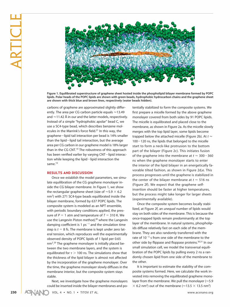
late equilibration of the CG graphene monolayer in-side the CG bilayer membrane. In Figure 1, we showthe rectangular graphene sheet (size of �5.9 � 6.2nm2) with 271 SC4-type beads equilibrated inside thebilayer membrane, formed by 637 POPC lipids. Thecomposite system is modeled as an NPT ensemble,with periodic boundary conditions applied, the pres-sure of P � 1 atm and temperature of T � 310 K. Weuse the Langevin Piston method,28 where the Langevindamping coefficient is 1 ps�1 and the simulation timestep is t � 8 fs. The membrane is kept under zero lat-eral tension, which reproduces well the experimentallyobserved density of POPC lipids of 1 lipid per 0.65nm2.29 The graphene monolayer is initially placed be-tween the two membrane layers, and the system isequilibrated for � � 100 ns. The simulations show thatthe thickness of the lipid bilayer is almost not affectedby the incorporation of the graphene monolayer. Overthe time, the graphene monolayer slowly diffuses in themembrane interior, but the composite system staysstable.
Next, we investigate how the graphene monolayerscould be inserted inside the bilayer membranes and po-
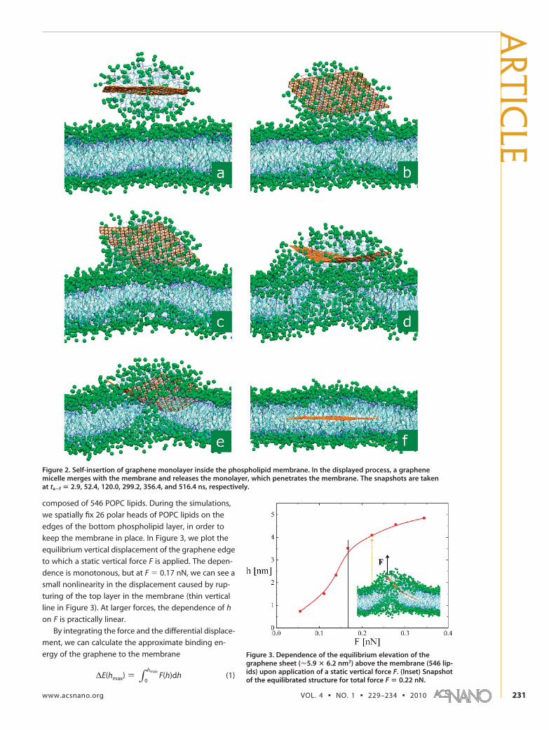
tentially stabilized to form the composite systems. We
first prepare a micelle formed by the above graphene
monolayer covered from both sides by 91 POPC lipids.
The micelle is equilibrated and placed close to the
membrane, as shown in Figure 2a. As the micelle slowly
merges with the top lipid layer, some lipids become
trapped below the attached micelle (Figure 2b). At t �
100�120 ns, the lipids that belonged to the micelle
start to form a neck-like protrusion to the bottom
part of the bilayer (Figure 2c). This initiates fusion
of the graphene into the membrane at t � 300�360
ns when the graphene monolayer starts to enter
the interior of the lipid bilayer in an energetically fa-
vorable tilted fashion, as shown in Figure 2d,e. This
process progresses until the graphene is stabilized in
the center of the bilayer membrane at t � 516 ns
(Figure 2f). We expect that the graphene self-
insertion should be faster at higher temperatures,
but the process might take longer for larger sheets
(experimentally available).
Once the composite system becomes locally stabi-
lized, at Figure 2f, an unequal number of lipids would
stay on both sides of the membrane. This is because the
once-trapped lipids remain predominantly at the top
layer of the membrane. In natural systems, phospholip-
ids diffuse relatively fast on each side of the mem-
brane. They are also randomly transferred with the
rate of 10�5 s from one side of the membrane to the
other side by flippase and floppase proteins.30,31 In our
small simulation cell, we model the transversal equili-
bration of the POPC lipids by pulling every 2 ns a ran-
domly chosen lipid from one side of the membrane to
the other.
It is important to estimate the stability of the com-
posite systems formed. Here, we calculate the work in-
vested into removing the equilibrated graphene mono-
layer from the membrane. We pull the monolayer (�5.9
� 6.2 nm2) out of the membrane (�13.5 � 13.5 nm2)
Figure 1. Equilibrated superstructure of graphene sheet hosted inside the phospholipid bilayer membrane formed by POPClipids. Polar heads of the POPC lipids are shown with green beads, hydrophobic hydrocarbon chains and the graphene sheetare shown with thick blue and brown lines, respectively (water beads hidden).
ART
ICLE
VOL. 4 ▪ NO. 1 ▪ TITOV ET AL. www.acsnano.org230
composed of 546 POPC lipids. During the simulations,
we spatially fix 26 polar heads of POPC lipids on the
edges of the bottom phospholipid layer, in order to
keep the membrane in place. In Figure 3, we plot the
equilibrium vertical displacement of the graphene edge
to which a static vertical force F is applied. The depen-
dence is monotonous, but at F � 0.17 nN, we can see a
small nonlinearity in the displacement caused by rup-
turing of the top layer in the membrane (thin vertical
line in Figure 3). At larger forces, the dependence of h
on F is practically linear.
By integrating the force and the differential displace-
ment, we can calculate the approximate binding en-
ergy of the graphene to the membrane Figure 3. Dependence of the equilibrium elevation of thegraphene sheet (�5.9 � 6.2 nm2) above the membrane (546 lip-ids) upon application of a static vertical force F. (Inset) Snapshotof the equilibrated structure for total force F � 0.22 nN.
Figure 2. Self-insertion of graphene monolayer inside the phospholipid membrane. In the displayed process, a graphenemicelle merges with the membrane and releases the monolayer, which penetrates the membrane. The snapshots are takenat ta�f � 2.9, 52.4, 120.0, 299.2, 356.4, and 516.4 ns, respectively.
∆E(hmax) ) ∫0
hmaxF(h)dh (1)
ARTIC
LE
www.acsnano.org VOL. 4 ▪ NO. 1 ▪ 229–234 ▪ 2010 231
Here, hmax is the final displacement of the graphene,
which depends on the total force F applied to it. From
eq 1, we obtain the graphene binding (extraction) en-
ergy of �E � 41.7 kcal/mol (66.9 kT) if we slowly in-
crease the total force from F � 0 to the chosen maxi-
mum value of Fmax � 0.35 nN. In the linear regime, we
can obtain the graphene binding energies of �E �
1.13 kcal/mol per nm2. These values confirm that
graphene monolayers can be stabilized in the hydro-
phobic interior of the bilayer membrane at room
temperature.
Finally, we briefly investigate if other composite
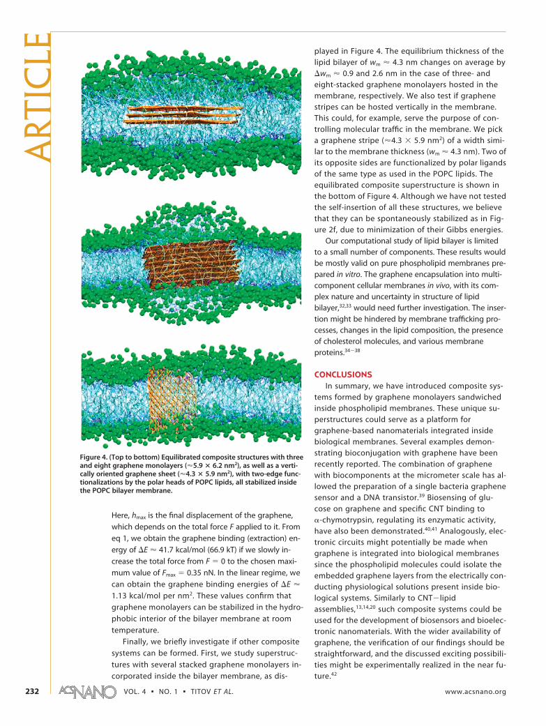
systems can be formed. First, we study superstruc-
tures with several stacked graphene monolayers in-
corporated inside the bilayer membrane, as dis-
played in Figure 4. The equilibrium thickness of thelipid bilayer of wm � 4.3 nm changes on average by�wm � 0.9 and 2.6 nm in the case of three- andeight-stacked graphene monolayers hosted in themembrane, respectively. We also test if graphenestripes can be hosted vertically in the membrane.This could, for example, serve the purpose of con-trolling molecular traffic in the membrane. We picka graphene stripe (�4.3 � 5.9 nm2) of a width simi-lar to the membrane thickness (wm � 4.3 nm). Two ofits opposite sides are functionalized by polar ligandsof the same type as used in the POPC lipids. Theequilibrated composite superstructure is shown inthe bottom of Figure 4. Although we have not testedthe self-insertion of all these structures, we believethat they can be spontaneously stabilized as in Fig-ure 2f, due to minimization of their Gibbs energies.
Our computational study of lipid bilayer is limitedto a small number of components. These results wouldbe mostly valid on pure phospholipid membranes pre-pared in vitro. The graphene encapsulation into multi-component cellular membranes in vivo, with its com-plex nature and uncertainty in structure of lipidbilayer,32,33 would need further investigation. The inser-tion might be hindered by membrane trafficking pro-cesses, changes in the lipid composition, the presenceof cholesterol molecules, and various membraneproteins.34�38
CONCLUSIONSIn summary, we have introduced composite sys-
tems formed by graphene monolayers sandwichedinside phospholipid membranes. These unique su-perstructures could serve as a platform forgraphene-based nanomaterials integrated insidebiological membranes. Several examples demon-strating bioconjugation with graphene have beenrecently reported. The combination of graphenewith biocomponents at the micrometer scale has al-lowed the preparation of a single bacteria graphenesensor and a DNA transistor.39 Biosensing of glu-cose on graphene and specific CNT binding to-chymotrypsin, regulating its enzymatic activity,have also been demonstrated.40,41 Analogously, elec-tronic circuits might potentially be made whengraphene is integrated into biological membranessince the phospholipid molecules could isolate theembedded graphene layers from the electrically con-ducting physiological solutions present inside bio-logical systems. Similarly to CNT�lipidassemblies,13,14,20 such composite systems could beused for the development of biosensors and bioelec-tronic nanomaterials. With the wider availability ofgraphene, the verification of our findings should bestraightforward, and the discussed exciting possibili-ties might be experimentally realized in the near fu-ture.42
Figure 4. (Top to bottom) Equilibrated composite structures with threeand eight graphene monolayers (�5.9 � 6.2 nm2), as well as a verti-cally oriented graphene sheet (�4.3 � 5.9 nm2), with two-edge func-tionalizations by the polar heads of POPC lipids, all stabilized insidethe POPC bilayer membrane.
ART
ICLE
VOL. 4 ▪ NO. 1 ▪ TITOV ET AL. www.acsnano.org232

SIMULATION DETAILSThe graphene is modeled with a triangular lattice of the SC4-
type beads, where the angular force constants and equilibriumangles are given by Kangle � 700 kcal mol�1 rad�2 and 0 � 60°, re-spectively. The dihedral angle force constants, multiplicity, andpotential minima are defined as K� � 3.1 kcal mol�1, n � 2, and� � 180°, respectively. Our CGMD simulation time flows aboutfour times faster than the all-atom MD simulation time.18
Proper modeling of the graphene elasticity is important forthe consistency of the CGMD simulations, even thoughgraphene sheets inside the lipid bilayers are not likely to be sub-jected to large stretching deformations. We calibrate the Young’smodulus in our CGMD model to the experimentally found elas-ticity of graphene. Experiments on bulk graphite give �1 TPa forthe in-plane Young’s modulus,43 while the Young’s modulus ingraphene varies between 0.5 and 1.0 TPa.44,45
To compare Young’s modulus with the macroscopic values,we keep one edge of the graphene sheet (�5.9 � 6.2 nm2) fixedand apply a constant force to the opposite edge. The normalstress is found as
where n is the number of CG beads with applied tensile force F,wg is the width and tg is the thickness of the graphene (separa-tion of graphene layers in graphite), respectively. In classical me-chanics the Young’s modulus is defined as
where l and �l are the equilibrium length of the graphene sheetand its change with the applied force, respectively. Our initial all-atom model of graphene yields its Young’s modulus of E � 0.9TPa, where the used bond and angular constants are 322.5 kcalmol�1 Å�2 and 53.35 kcal mol�1 rad�2, respectively. We have re-alized that, in order to have a similar Young’s modulus in theCGMD model, we need to adjust these constants to 700 kcalmol�1 Å �2 and 700 kcal mol�1 rad�2, respectively. When westretch this system in simulations and use eqs 2 and 3, we ob-tain ECGMD � 928 GPa for the graphene sheet with n � 9, wg �5.9 nm, tg � 0.34 nm, F � 69.47 pN, and �l/l � 0.00034. How-ever, the stiffness of the model graphene is less important for thebehavior of the described composite planar systems, as con-firmed in our modeling.
Acknowledgment. We acknowledge Aleksei Aksimentiev andRogan Carr for discussions of the CG simulations. A.T. acknowl-edges the UIC Office of Research for support.
Supporting Information Available: Video of graphene inser-tion into the POPC bilayer. This material is available free ofcharge via the Internet at http://pubs.acs.org.
REFERENCES AND NOTES1. Novoselov, K. S.; Geim, A. K.; Morozov, S. V.; Jiang, D.;
Katsnelson, M. I.; Grigorieva, I. V.; Dubonos, S. V.; Firsov,A. A. Two-Dimensional Gas of Massless Dirac Fermions inGraphene. Nature 2005, 438, 197–200.
2. Miao, F.; Wijeratne, S.; Zhang, Y.; Coskun, U. C.; Bao, W.;Lau, C. N. Phase-Coherent Transport in GrapheneQuantum Billiards. Science 2007, 317, 1530–1533.
3. Castro, E. V.; Novoselov, K. S.; Morozov, S. V.; Peres,N. M. R.; Dos Santos, J. M. B. L.; Nilsson, J.; Guinea, F.; Geim,A. K.; Neto, A. H. C. Biased Bilayer Graphene:Semiconductor with a Gap Tunable by the Electric FieldEffect. Phys. Rev. Lett. 2007, 99, 216802.
4. Ponomarenko, L. A.; Schedin, F.; Katsnelson, M. I.; Yang, R.;Hill, E. W.; Novoselov, K. S.; Geim, A. K. Chaotic DiracBilliard in Graphene Quantum Dots. Science 2008, 320,356–358.
5. Saito, R.; Fujita, M.; Dresselhaus, G.; Dresselhaus, M. S.Electronic Structure of Chiral Graphene Tubules. Appl.Phys. Lett. 1992, 60, 2204–2206.
6. Avouris, P.; Chen, Z. H.; Perebeinos, V. Carbon-BasedElectronics. Nat. Nano 2007, 2, 605–615.
7. Stankovich, S.; Dikin, D. A.; Dommett, G. H. B.; Kohlhaas,K. M.; Zimney, E. J.; Stach, E. A.; Piner, R. D.; Nguyen, S. T.;Ruoff, R. S. Graphene-Based Composite Materials. Nature2006, 442, 282–286.
8. Dikin, D. A.; Stankovich, S.; Zimney, E. J.; Piner, R. D.;Dommett, G. H. B.; Evmenenko, G.; Nguyen, S. T.; Ruoff,R. S. Preparation and Characterization of Graphene OxidePaper. Nature 2007, 448, 457–460.
9. Cervantes-Sodi, F.; Csanyi, G.; Piscanec, S.; Ferrari, A. C.Edge-Functionalized and Substitutionally DopedGraphene Nanoribbons: Electronic and Spin Properties.Phys. Rev. B 2008, 77, 165427.
10. Boukhvalov, D. W.; Katsnelson, M. I. ChemicalFunctionalization of Graphene with Defects. Nano Lett.2008, 8, 4373–4379.
11. Kral, P. Control of Catalytic Activity of Proteins In Vivo byNanotube Ropes Excited with Infrared Light. Chem. Phys.Lett. 2003, 382, 399–403.
12. Konatham, D.; Striolo, A. Molecular Design of StableGraphene Nanosheets Dispersions. Nano Lett. 2008, 8,4630–4641.
13. Richard, C.; Balavoine, F.; Schultz, P.; Ebbesen, T. W.;Mioskowski, C. Supramolecular Self-Assembly of LipidDerivatives on Carbon Nanotubes. Science 2003, 300, 775–778.
14. Thauvin, C.; Rickling, S.; Schultz, P.; Celia, H.; Meunier, S.;Mioskowski, C. Carbon Nanotubes as Templates forPolymerized Lipid Assemblies. Nat. Nano 2008, 3,743–748.
15. Wong-Ekkabut, J.; Baoukina, S.; Triampo, W.; Tang, I.-M.;Tieleman, D. P.; Monticelli, L. Computer Simulation Studyof Fullerene Translocation through Lipid Membranes. Nat.Nano 2008, 3, 363–368.
16. Carr, R.; Weinstock, I. A.; Sivaprasadarao, A.; Muller, A.;Aksimentiev, A. Synthetic Ion Channels via Self-Assembly:A Route for Embedding Porous PolyoxometalateNanocapsules in Lipid Bilayer Membranes. Nano Lett.2008, 8, 3916–3921.
17. Neri, M.; Baaden, M.; Carnevale, V.; Anselmi, C.; Maritan, A.;Carloni, P. Microseconds Dynamics Simulations of theOuter-Membrane Protease T. Biophys. J. 2008, 94, 71–78.
18. Marrink, S.; deVries, A.; Mark, A. Coarse Grained Model forSemiquantitative Lipid Simulations. J. Phys. Chem. B 2004,108, 750–760.
19. Wallace, E. J.; Sansom, M. S. P. CarbonNanotube/Detergent Interactions via Coarse-GrainedMolecular Dynamics. Nano Lett. 2007, 7, 1923–1928.
20. Wallace, E. J.; Sansom, M. S. P. Carbon Nanotube Self-Assembly with Lipids and Detergent: A MolecularDynamics Study. Nanotechnology 2009, 20, 045101.
21. Marrink, S. J.; Risselada, H. J.; Yefimov, S.; Tieleman, D. P.;de Vries, A. H. The MARTINI Force Field: Coarse GrainedModel for Biomolecular Simulations. J. Phys. Chem. B 2007,111, 7812–7824.
22. Phillips, J. C.; Braun, R.; Wang, W.; Gumbart, J.; Tajkhorshid,E.; Villa, E.; Chipot, C.; Skeel, R. D.; Kale, L.; Schulten, K.;Schulten, K. Scalable Molecular Dynamics with NAMD.J. Comput. Chem. 2005, 26, 1781–1802.
23. Humphrey, W.; Dalke, A.; Schulten, K. VMD: VisualMolecular Dynamics. J. Mol. Graph. 1996, 14, 33.
24. Shih, A. Y.; Freddolino, P. L.; Arkhipov, A.; Schulten, K.Assembly of Lipoprotein Particles Revealed by Coarse-Grained Molecular Dynamics Simulations. J. Struct. Biol.2007, 157, 579–592.
25. O’Connell, M. J.; et al. Band Gap Fluorescence fromIndividual Single-Walled Carbon Nanotubes. Science 2002,297, 593–596.
26. Moore, V. C.; Strano, M. S.; Haroz, E. H.; Hauge, R. H.;Smalley, R. E.; Schmidt, J.; Talmon, Y. IndividuallySuspended Single-Walled Carbon Nanotubes in VariousSurfactants. Nano Lett. 2003, 3, 1379–1382.
σ ) nFwgtg
(2)
E ) σ∆l/l
(3)
ARTIC
LE
www.acsnano.org VOL. 4 ▪ NO. 1 ▪ 229–234 ▪ 2010 233

27. Wu, Y.; Hudson, J. S.; Lu, Q.; Moore, J. M.; Mount, A. S.; Rao,A. M.; Alexov, E.; Ke, P. C. Coating Single-Walled CarbonNanotubes with Phospholipids. J. Phys. Chem. B 2006, 110,2475–2478.
28. Feller, S. E.; Zhang, Y. H.; Pastor, R. W.; Brooks, B. R.Constant-Pressure Molecular-Dynamics SimulationOTheLangevin Piston Method. J. Chem. Phys. 1995, 103,4613–4621.
29. Lantzsch, G.; Binder, H.; Heerklotz, H. Surface Area PerMolecule in Lipid/c12en Membranes As Seen byFluorescence Resonance Energy Transfer. J. Fluoresc. 1994,4, 339–343.
30. Liu, J.; Conboy, J. C. Kinetics and Thermodynamics ofAssociation of a Phospholipid Derivative with LipidBilayers in Liquid-Disordered and Liquid-Ordered Phases.Biophys. J. 2005, 89, 2522–2532.
31. Abreu, M. S.; Moreno, M. J.; Vaz, W. L. Kinetics andThermodynamics of Association of a PhospholipidDerivative with Lipid Bilayers in Liquid-Disordered andLiquid-Ordered Phases. Biophys. J. 2004, 87, 353–365.
32. Israelachvili, J. N.; Mitchell, D. J.; Ninham, B. W. Theory ofSelf-Assembly of Hydrocarbon Amphiphiles into Micellesand Bilayers. J. Chem. Soc., Faraday Trans. 2 1976, 72,1525–1568.
33. Nagle, J. F.; Tristram-Nagle, S. Structure of Lipid Bilayers.Biochim. Biophys. Acta 2000, 1469, 159–195.
34. Doyle, D. A.; Cabral, J. M.; Pfuetzner, R. A.; Kuo, A. L.; Gulbis,J. M.; Cohen, S. L.; Chait, B. T.; MacKinnon, R. The Structureof the Potassium Channel: Molecular Basis of K
Conduction and Selectivity. Science 1998, 280, 69–77.35. Ohvo-Rekila, H.; Ramstedt, B.; Leppimaki, P.; Slotte, J. P.
Cholesterol Interactions with Phospholipids inMembranes. Prog. Lipid Res. 2002, 41, 66–97.
36. Palczewski, K.; et al. Crystal Structure of Rhodopsin: A GProtein-Coupled Receptor. Science 2000, 289, 739–745.
37. Peter, B. J.; Kent, H. M.; Mills, I. G.; Vallis, Y.; Butler, P. J. G.;Evans, P. R.; McMahon, H. T. BAR Domains As Sensors ofMembrane Curvature: The Amphiphysin BAR Structure.Science 2004, 303, 495–499.
38. McMahon, H. T.; Gallop, J. L. Membrane Curvature andMechanisms of Dynamic Cell Membrane Remodelling.Nature 2005, 438, 590–596.
39. Mohanty, N.; Berry, V. Graphene-Based Single-BacteriumResolution Biodevice and DNA Transistor: InterfacingGraphene Derivatives with Nanoscale and MicroscaleBiocomponents. Nano Lett. 2008, 8, 4469–4476.
40. Shan, C.; Yang, H.; Song, J.; Han, D.; Ivaska, A.; Niu, L. DirectElectrochemistry of Glucose Oxidase and Biosensing forGlucose Based on Graphene. Anal. Chem. 2009, 81, 2378–2382.
41. Zhang, B.; Xing, Y.; Li, Z.; Zhou, H.; Mu, Q.; Yan, B.Functionalized Carbon Nanotubes Specifically Bind to -Chymotrypsin’s Catalytic Site and Regulate Its EnzymaticFunction. Nano Lett. 2009, 9, 2280–2284.
42. Kim, K. S.; Zhao, Y.; Jang, H.; Lee, S. Y.; Kim, J. M.; Kim, K. S.;Ahn, J.-H.; Kim, P.; Choi, J.-Y.; Hong, B. H. Large-ScalePattern Growth of Graphene Films for StretchableTransparent Electrodes. Nature 2009, 457, 706–710.
43. Blakslee, O. L.; Proctor, D. G.; Seldin, E. J.; Spence, G. B.;Weng, T. Elastic Constants of Compression-AnnealedPyrolytic Graphite. J. Appl. Phys. 1970, 41, 3373–3382.
44. Frank, I. W.; Tanenbaum, D. M.; van der Zande, A. M.;McEuen, P. L. Mechanical Properties of SuspendedGraphene Sheets. J. Vac. Sci. Technol., B 2007, 25,2558–2561.
45. Lee, C.; Wei, X.; Kysar, J. W.; Hone, J. Measurement of theElastic Properties and Intrinsic Strength of MonolayerGraphene. Science 2008, 321, 385–388.
ART
ICLE
VOL. 4 ▪ NO. 1 ▪ TITOV ET AL. www.acsnano.org234