Embed Size (px)
Citation preview
Design and Implementation of Magnetron Power Supply and Emulator
Nourdeen A. Abodhir, Alan J. Watson, Chao Ji, Jon C. Clare
University of Nottingham, Nottingham, NG7 2RD, U.K. Email: [email protected]
Key words: Resonant converter control, variable load, magnetron
Abstract The paper presents a novel resonant based high performance power converter solution for industrial magnetron systems. Based the characteristics of the magnetron, an emulator prototype is also proposed to represent the magnetron load behaviour in a laboratory environment. A detailed design and implementation procedure is presented, including the design and control of the resonant power converter, together with the magnetron emulator in practical aspects. Experimental results are provided in order to demonstrate the feasibility of the proposed converter and emulator.
1-Introduction
Industrial magnetrons are becoming increasingly more common in a wide range of applications such as the production of food-stuffs, chemicals, textiles, paper and wood materials [1]. Since a high DC voltage is required in order to drive magnetrons, the heart of any microwave energy generator contains a high voltage DC power supply [2]. Traditional drive systems for high power radio frequency (RF) applications such as Magnetrons and Klystrons are based on 50/60 Hz line frequency voltage scaling components, which implies a bulky system volume.
Resonant power converters have been considered for their high efficiency and high power density features to replace the traditional approaches. The main advantage of using the resonant converters with high-frequency operation is the smaller size and lighter weight of the passive components used [3]. Also, as demonstrated in [4], it is possible to operate the semiconductors at these higher switching frequencies without significantly compromising converter efficiency.
For various target applications, different load resonant converter topologies with associated modulation and control techniques, such as combined frequency and phase shift modulation (CFPM) and DQ modelling, have been proposed in previous work [5-8]. The CFPM modulation technique can be applied directly to modulate high power resonant converters with fixed load conditions. However, in some industrial microwave applications, it is required to operate with a wide operating range for different output requirements. This essential feature results in a variable load resistance seen by the power converter, which not only affects the converter control and modulation, but also compromises the soft-switching scheme.
With the aim of overcoming the aforementioned limitations, a control method based on three dimensional (3D) lookup tables approach has been developed in order to modulate the load resonant converter whilst maintaining soft switching under variable load conditions. For this method the soft switching points for a whole operating range are pre-calculated and represented in a 3D lookup table. Hence, during the converter modulation, the soft switching point (Zero Current Switching ZCS or Zero Voltage switching) can be tracked by obtaining the online value of the variable load resistance (consequently the load Quality Factor can be calculated) and the control actuation signal.
In this paper a compact power converter is designed to supply a magnetron under variable load conditions. Since the quality of the produced RF energy is a function of Magnetron’s Anode current, a controllable current source is formed, using the load resonant converter in the form of a Series Resonant Series Loaded (SRSL) converter topology. In order to examine the proposed converter topology and associated control strategy, and to avoid unnecessary cost and the production of high voltage; a reduced scale power electronics based magnetron emulator was also proposed and developed.
2-Proposed converter
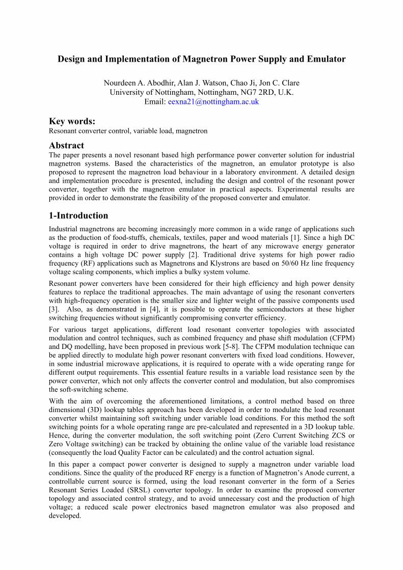
Figure 1 shows the topology of the proposed SRSL power converter for industrial magnetron drives which comprises of a three phase rectifier, DC link capacitors, H-bridge inverter, resonant tank, transformer, rectifier, filter, magnetron equivalent circuit, associated measurement and control system.
Figure 1 SRSL based power converter topology for industrial magnetron drives.
The single phase full bridge inverter excites the resonant tank with a high frequency quasi-square wave voltage. The high frequency, high voltage transformer is utilised to step up the voltage to the necessary level required by the magnetron load. The tank current is rectified and filtered by using a diode bridge rectifier and a capacitance filter to produce a smooth DC output voltage. The input three-phase rectifier can be excluded from the scope of operation analysis and the DC-link capacitor can be treated as a constant DC voltage source.
For simplicity, in the following design and steady state analysis the load is modelled as resistive load, (R). By assuming that the resonant tank is reasonably selective and the inverter is switched around the resonant frequency, the fundamental mode approximation can be utilised to simplify the inverter output analysis [3]. The equivalent circuit of the proposed converter is shown in figure 2, while the specifications and design results are listed in table I.
Figure 2 the equivalent circuit of the proposed converter
Table I: power supply specifications and design results
Description Symbol Value Description Symbol Value
Power Supply
Specifications
Load voltage Vf 180V-300V
Design Results
Tank inductor L 0.787mH Load voltage
ripple Vripple <3% Tank capacitor C 72 nF
Load current Iout 6A-10A Resonant frequency fo 21.14kHz Output power P 1.8kW-3kW Filter capacitor Cf 9.6μF Quality factor Q 2.5 - 5 Emulator capacitor Cemulator 160 μF
Switching frequency
Fsw 21.2-24.3kHz Emulator resistor Remulator 15ohm
DC-Link voltage VDC 400V Slope resistor Rslope 5ohm
3-Magnetron Emulator
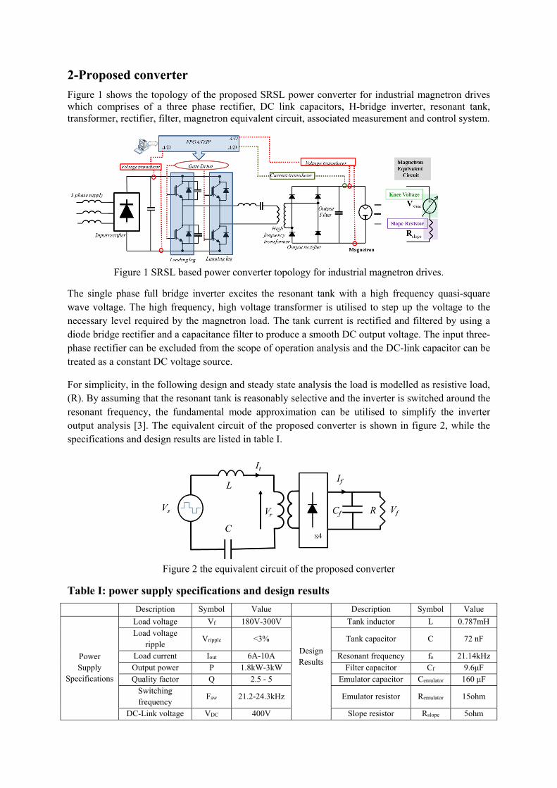
For an industrial magnetron, the quality of the produced radio frequency RF energy is a function of the anode current. The typical relationship between the magnetron anode voltage and current is shown in figure 3. The increase in the anode voltage causes insignificant rise in the anode current until a knee voltage Vknee, is reached. After this knee voltage point the current is raised dramatically giving a dynamic slope resistance (Rslope). For the industrial magnetron to work, the applied anode voltage must be greater than the knee voltage (Va >Vknee).
Figure 3 the typical relationship between the anode voltage and current
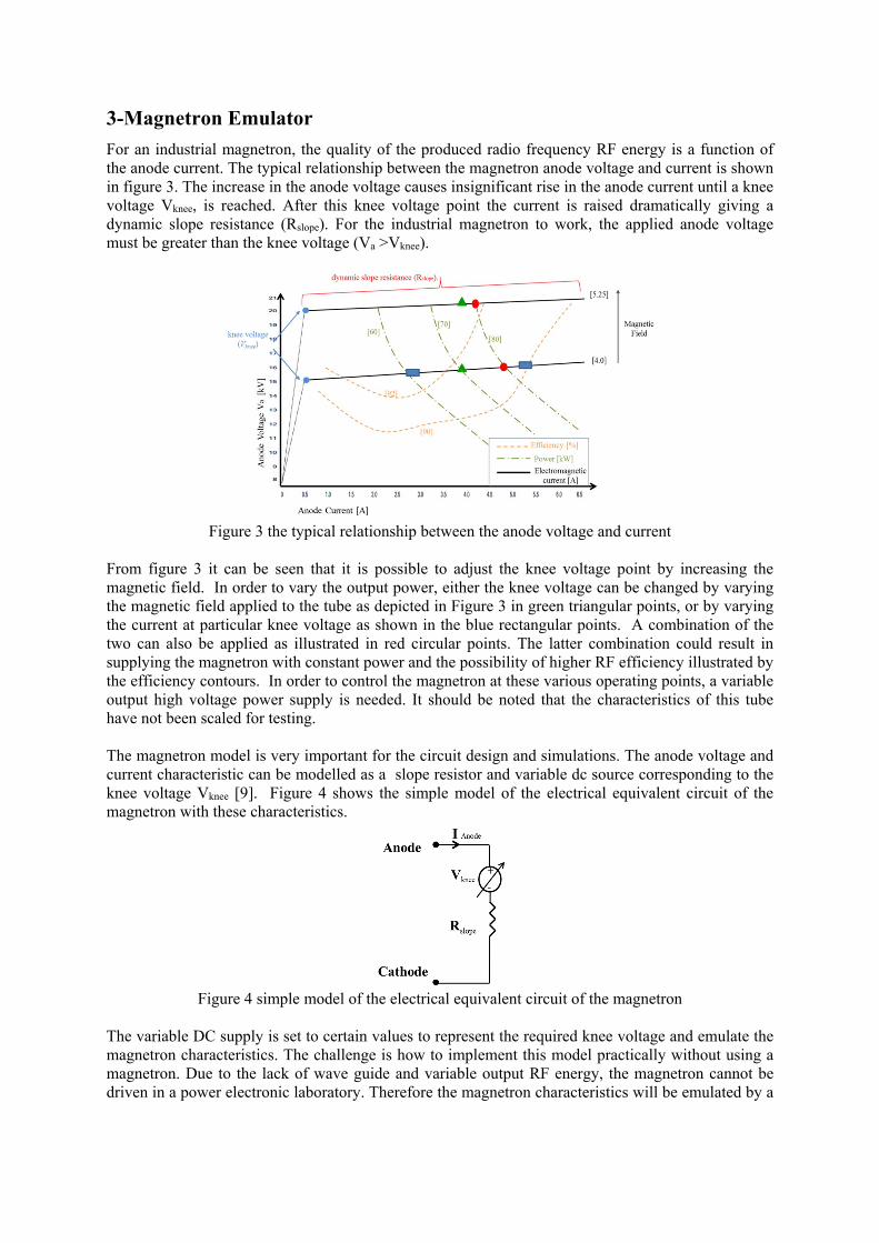
From figure 3 it can be seen that it is possible to adjust the knee voltage point by increasing the magnetic field. In order to vary the output power, either the knee voltage can be changed by varying the magnetic field applied to the tube as depicted in Figure 3 in green triangular points, or by varying the current at particular knee voltage as shown in the blue rectangular points. A combination of the two can also be applied as illustrated in red circular points. The latter combination could result in supplying the magnetron with constant power and the possibility of higher RF efficiency illustrated by the efficiency contours. In order to control the magnetron at these various operating points, a variable output high voltage power supply is needed. It should be noted that the characteristics of this tube have not been scaled for testing. The magnetron model is very important for the circuit design and simulations. The anode voltage and current characteristic can be modelled as a slope resistor and variable dc source corresponding to the knee voltage Vknee [9]. Figure 4 shows the simple model of the electrical equivalent circuit of the magnetron with these characteristics.
Figure 4 simple model of the electrical equivalent circuit of the magnetron
The variable DC supply is set to certain values to represent the required knee voltage and emulate the magnetron characteristics. The challenge is how to implement this model practically without using a magnetron. Due to the lack of wave guide and variable output RF energy, the magnetron cannot be driven in a power electronic laboratory. Therefore the magnetron characteristics will be emulated by a
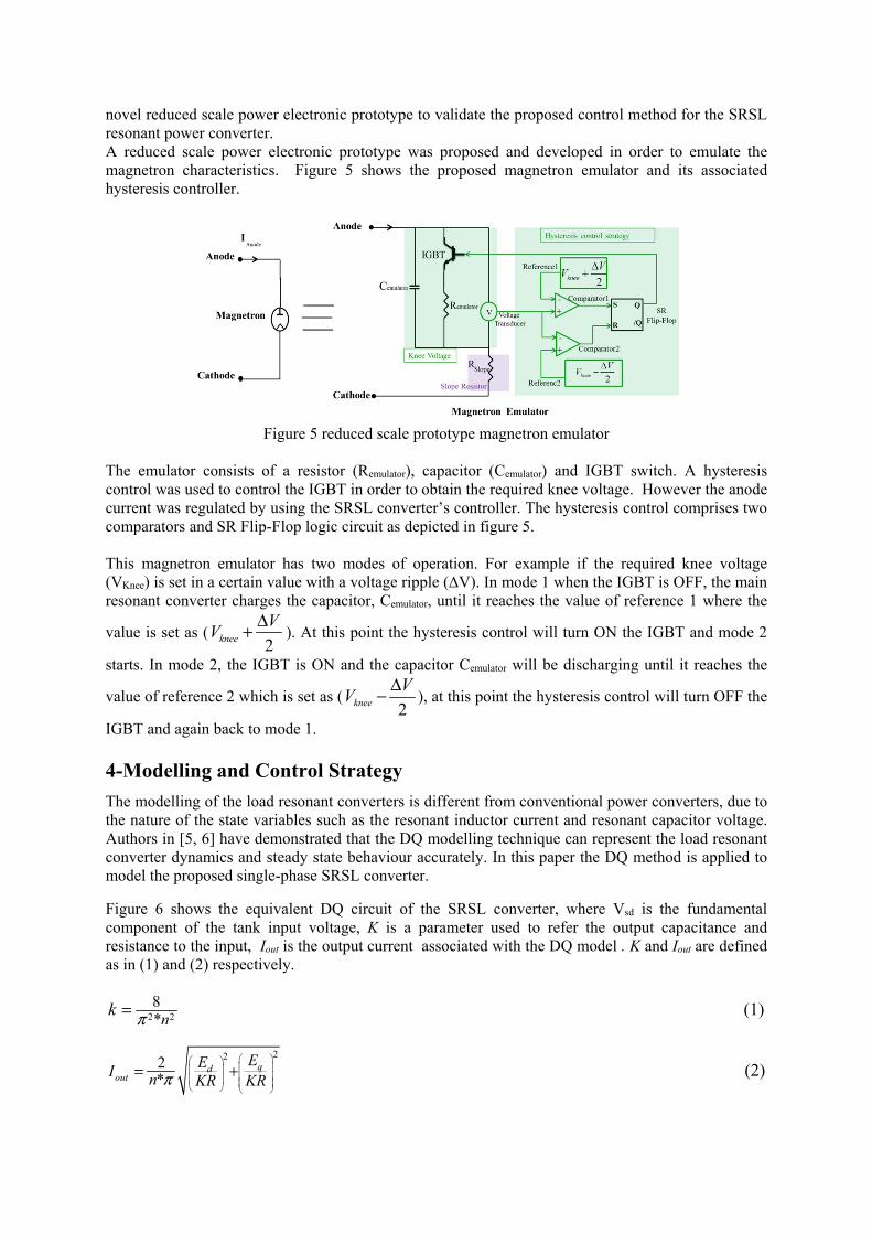
novel reduced scale power electronic prototype to validate the proposed control method for the SRSL resonant power converter. A reduced scale power electronic prototype was proposed and developed in order to emulate the magnetron characteristics. Figure 5 shows the proposed magnetron emulator and its associated hysteresis controller.
Figure 5 reduced scale prototype magnetron emulator
The emulator consists of a resistor (Remulator), capacitor (Cemulator) and IGBT switch. A hysteresis control was used to control the IGBT in order to obtain the required knee voltage. However the anode current was regulated by using the SRSL converter’s controller. The hysteresis control comprises two comparators and SR Flip-Flop logic circuit as depicted in figure 5. This magnetron emulator has two modes of operation. For example if the required knee voltage (VKnee) is set in a certain value with a voltage ripple (∆V). In mode 1 when the IGBT is OFF, the main resonant converter charges the capacitor, Cemulator, until it reaches the value of reference 1 where the
value is set as (2knee
VV
Δ+ ). At this point the hysteresis control will turn ON the IGBT and mode 2
starts. In mode 2, the IGBT is ON and the capacitor Cemulator will be discharging until it reaches the
value of reference 2 which is set as (2knee
VV
Δ− ), at this point the hysteresis control will turn OFF the
IGBT and again back to mode 1. 4-Modelling and Control Strategy
The modelling of the load resonant converters is different from conventional power converters, due to the nature of the state variables such as the resonant inductor current and resonant capacitor voltage. Authors in [5, 6] have demonstrated that the DQ modelling technique can represent the load resonant converter dynamics and steady state behaviour accurately. In this paper the DQ method is applied to model the proposed single-phase SRSL converter.
Figure 6 shows the equivalent DQ circuit of the SRSL converter, where Vsd is the fundamental component of the tank input voltage, K is a parameter used to refer the output capacitance and resistance to the input, Iout is the output current associated with the DQ model . K and Iout are defined as in (1) and (2) respectively.
2 28*n
k π= (1)
222*
qdout
EEI n KR KRπ
= + (2)
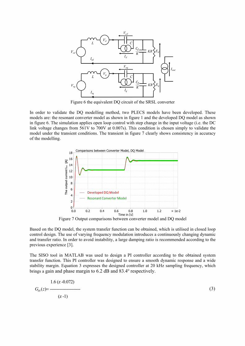
Figure 6 the equivalent DQ circuit of the SRSL converter
In order to validate the DQ modelling method, two PLECS models have been developed. These models are: the resonant converter model as shown in figure 1 and the developed DQ model as shown in figure 6. The simulation applies open loop control with step change in the input voltage (i.e. the DC link voltage changes from 561V to 700V at 0.007s). This condition is chosen simply to validate the model under the transient conditions. The transient in figure 7 clearly shows consistency in accuracy of the modelling.
Figure 7 Output comparisons between converter model and DQ model
Based on the DQ model, the system transfer function can be obtained, which is utilised in closed loop control design. The use of varying frequency modulation introduces a continuously changing dynamic and transfer ratio. In order to avoid instability, a large damping ratio is recommended according to the previous experience [3]. The SISO tool in MATLAB was used to design a PI controller according to the obtained system transfer function. This PI controller was designed to ensure a smooth dynamic response and a wide stability margin. Equation 3 expresses the designed controller at 20 kHz sampling frequency, which brings a gain and phase margin to 6.2 dB and 83.4o respectively.
1.6 (z -0.072)
( ) ----------------------
(z -1)PIG z = (3)
5-Modulation
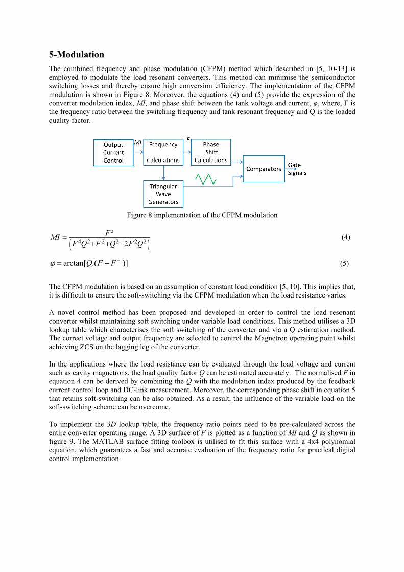
The combined frequency and phase modulation (CFPM) method which described in [5, 10-13] is employed to modulate the load resonant converters. This method can minimise the semiconductor switching losses and thereby ensure high conversion efficiency. The implementation of the CFPM modulation is shown in Figure 8. Moreover, the equations (4) and (5) provide the expression of the converter modulation index, MI, and phase shift between the tank voltage and current, φ, where, F is the frequency ratio between the switching frequency and tank resonant frequency and Q is the loaded quality factor.
Figure 8 implementation of the CFPM modulation
( )2
4 2 2 2 2 22FMI
F Q F Q F Q=
+ + − (4)
1arctan[ .( )]Q F Fϕ −= − (5)
The CFPM modulation is based on an assumption of constant load condition [5, 10]. This implies that, it is difficult to ensure the soft-switching via the CFPM modulation when the load resistance varies. A novel control method has been proposed and developed in order to control the load resonant converter whilst maintaining soft switching under variable load conditions. This method utilises a 3D lookup table which characterises the soft switching of the converter and via a Q estimation method. The correct voltage and output frequency are selected to control the Magnetron operating point whilst achieving ZCS on the lagging leg of the converter. In the applications where the load resistance can be evaluated through the load voltage and current such as cavity magnetrons, the load quality factor Q can be estimated accurately. The normalised F in equation 4 can be derived by combining the Q with the modulation index produced by the feedback current control loop and DC-link measurement. Moreover, the corresponding phase shift in equation 5 that retains soft-switching can be also obtained. As a result, the influence of the variable load on the soft-switching scheme can be overcome. To implement the 3D lookup table, the frequency ratio points need to be pre-calculated across the entire converter operating range. A 3D surface of F is plotted as a function of MI and Q as shown in figure 9. The MATLAB surface fitting toolbox is utilised to fit this surface with a 4x4 polynomial equation, which guarantees a fast and accurate evaluation of the frequency ratio for practical digital control implementation.
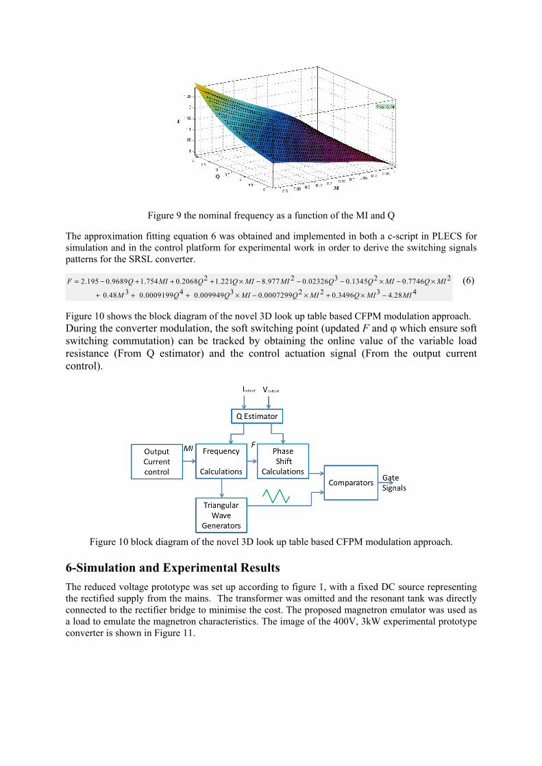
Figure 9 the nominal frequency as a function of the MI and Q
The approximation fitting equation 6 was obtained and implemented in both a c-script in PLECS for simulation and in the control platform for experimental work in order to derive the switching signals patterns for the SRSL converter.
2 2 3 2 22.195 0.9689 1.754 0.2068 1.221 8.977 0.02326 0.1345 0.7746
3 4 3 2 2 3 4 0.48 0.0009199 0.009949 0.0007299 0.3496 4.28
F Q MI Q Q MI MI Q Q MI Q MI
M Q Q MI Q MI Q MI MI
= − + + + × − − − × − ×
+ + + × − × + × −
(6)
Figure 10 shows the block diagram of the novel 3D look up table based CFPM modulation approach. During the converter modulation, the soft switching point (updated F and φ which ensure soft switching commutation) can be tracked by obtaining the online value of the variable load resistance (From Q estimator) and the control actuation signal (From the output current control).
Figure 10 block diagram of the novel 3D look up table based CFPM modulation approach.
6-Simulation and Experimental Results
The reduced voltage prototype was set up according to figure 1, with a fixed DC source representing the rectified supply from the mains. The transformer was omitted and the resonant tank was directly connected to the rectifier bridge to minimise the cost. The proposed magnetron emulator was used as a load to emulate the magnetron characteristics. The image of the 400V, 3kW experimental prototype converter is shown in Figure 11.
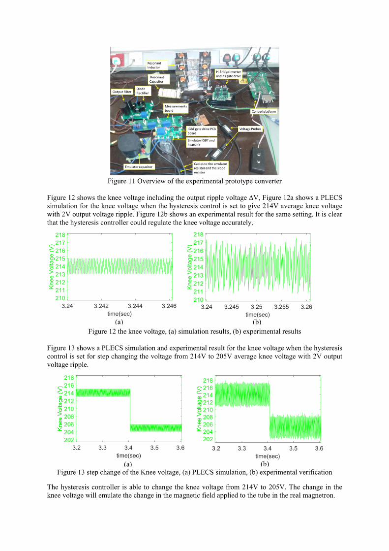
Figure 11 Overview of the experimental prototype converter
Figure 12 shows the knee voltage including the output ripple voltage ∆V, Figure 12a shows a PLECS simulation for the knee voltage when the hysteresis control is set to give 214V average knee voltage with 2V output voltage ripple. Figure 12b shows an experimental result for the same setting. It is clear that the hysteresis controller could regulate the knee voltage accurately.
Figure 12 the knee voltage, (a) simulation results, (b) experimental results Figure 13 shows a PLECS simulation and experimental result for the knee voltage when the hysteresis control is set for step changing the voltage from 214V to 205V average knee voltage with 2V output voltage ripple.
Figure 13 step change of the Knee voltage, (a) PLECS simulation, (b) experimental verification
The hysteresis controller is able to change the knee voltage from 214V to 205V. The change in the knee voltage will emulate the change in the magnetic field applied to the tube in the real magnetron.
time(sec)3.24 3.242 3.244 3.246
Kne
e V
olta
ge (V
)
210211212213214215216217218
time(sec)3.24 3.245 3.25 3.255 3.26
Kne
e V
olta
ge (V
)
210211212213214215216217218
time(sec)3.2 3.3 3.4 3.5 3.6
202204206208210212214216218
time(sec)3.2 3.3 3.4 3.5 3.6
202204206208210212214216218
(a) (b)
(a) (b)
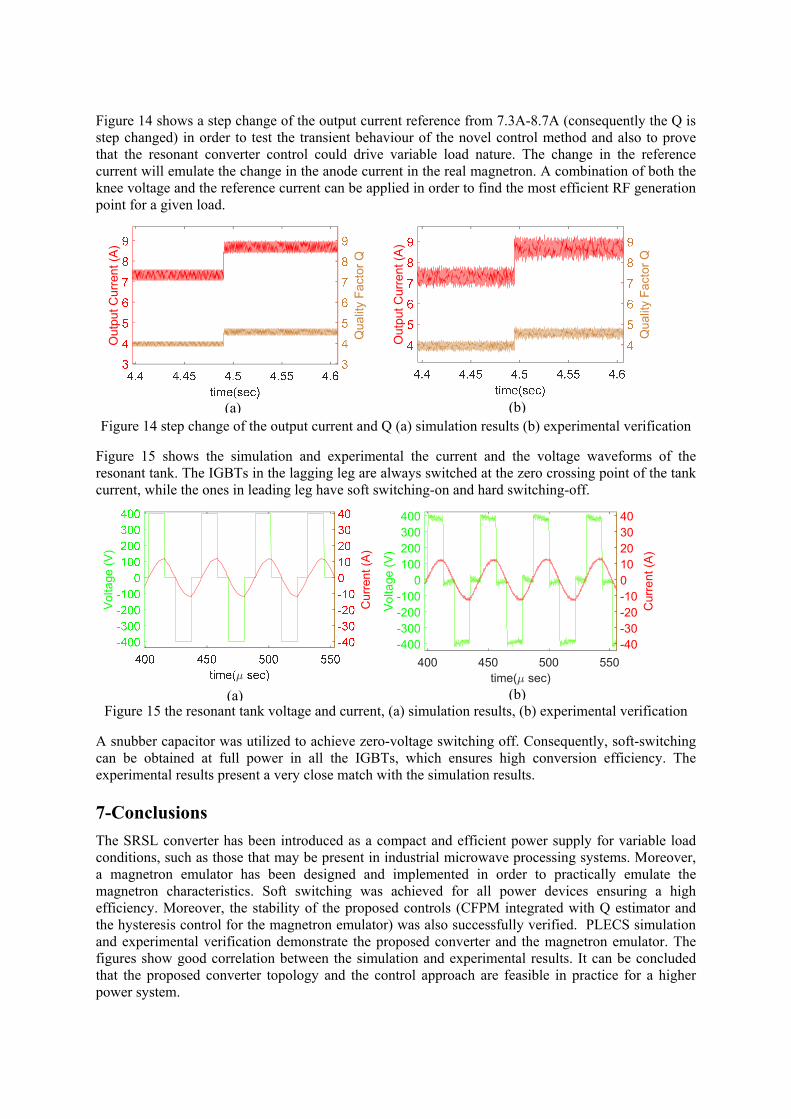
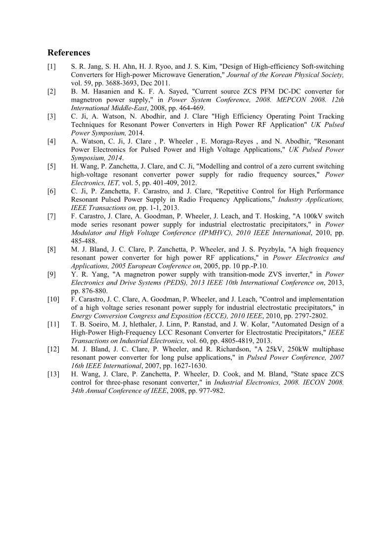
Figure 14 shows a step change of the output current reference from 7.3A-8.7A (consequently the Q is step changed) in order to test the transient behaviour of the novel control method and also to prove that the resonant converter control could drive variable load nature. The change in the reference current will emulate the change in the anode current in the real magnetron. A combination of both the knee voltage and the reference current can be applied in order to find the most efficient RF generation point for a given load.
Figure 14 step change of the output current and Q (a) simulation results (b) experimental verification
Figure 15 shows the simulation and experimental the current and the voltage waveforms of the resonant tank. The IGBTs in the lagging leg are always switched at the zero crossing point of the tank current, while the ones in leading leg have soft switching-on and hard switching-off.
Figure 15 the resonant tank voltage and current, (a) simulation results, (b) experimental verification
A snubber capacitor was utilized to achieve zero-voltage switching off. Consequently, soft-switching can be obtained at full power in all the IGBTs, which ensures high conversion efficiency. The experimental results present a very close match with the simulation results. 7-Conclusions
The SRSL converter has been introduced as a compact and efficient power supply for variable load conditions, such as those that may be present in industrial microwave processing systems. Moreover, a magnetron emulator has been designed and implemented in order to practically emulate the magnetron characteristics. Soft switching was achieved for all power devices ensuring a high efficiency. Moreover, the stability of the proposed controls (CFPM integrated with Q estimator and the hysteresis control for the magnetron emulator) was also successfully verified. PLECS simulation and experimental verification demonstrate the proposed converter and the magnetron emulator. The figures show good correlation between the simulation and experimental results. It can be concluded that the proposed converter topology and the control approach are feasible in practice for a higher power system.
Out
put C
urre
nt (A
)
Qua
lity
Fact
or Q
Out
put C
urre
nt (A
)
Qua
lity
Fact
or Q
Vol
tage
(V)
Cur
rent
(A)
time( sec)400 450 500 550
Vol
tage
(V)
-400-300-200-100
0100200300400
Cur
rent
(A)
-40-30-20-10010203040
(b)
(b)
(a)
(a)
References
[1] S. R. Jang, S. H. Ahn, H. J. Ryoo, and J. S. Kim, "Design of High-efficiency Soft-switching Converters for High-power Microwave Generation," Journal of the Korean Physical Society, vol. 59, pp. 3688-3693, Dec 2011.
[2] B. M. Hasanien and K. F. A. Sayed, "Current source ZCS PFM DC-DC converter for magnetron power supply," in Power System Conference, 2008. MEPCON 2008. 12th International Middle-East, 2008, pp. 464-469.
[3] C. Ji, A. Watson, N. Abodhir, and J. Clare "High Efficiency Operating Point Tracking Techniques for Resonant Power Converters in High Power RF Application" UK Pulsed Power Symposium, 2014.
[4] A. Watson, C. Ji, J. Clare , P. Wheeler , E. Moraga-Reyes , and N. Abodhir, "Resonant Power Electronics for Pulsed Power and High Voltage Applications," UK Pulsed Power Symposium, 2014.
[5] H. Wang, P. Zanchetta, J. Clare, and C. Ji, "Modelling and control of a zero current switching high-voltage resonant converter power supply for radio frequency sources," Power Electronics, IET, vol. 5, pp. 401-409, 2012.
[6] C. Ji, P. Zanchetta, F. Carastro, and J. Clare, "Repetitive Control for High Performance Resonant Pulsed Power Supply in Radio Frequency Applications," Industry Applications, IEEE Transactions on, pp. 1-1, 2013.
[7] F. Carastro, J. Clare, A. Goodman, P. Wheeler, J. Leach, and T. Hosking, "A 100kV switch mode series resonant power supply for industrial electrostatic precipitators," in Power Modulator and High Voltage Conference (IPMHVC), 2010 IEEE International, 2010, pp. 485-488.
[8] M. J. Bland, J. C. Clare, P. Zanchetta, P. Wheeler, and J. S. Pryzbyla, "A high frequency resonant power converter for high power RF applications," in Power Electronics and Applications, 2005 European Conference on, 2005, pp. 10 pp.-P.10.
[9] Y. R. Yang, "A magnetron power supply with transition-mode ZVS inverter," in Power Electronics and Drive Systems (PEDS), 2013 IEEE 10th International Conference on, 2013, pp. 876-880.
[10] F. Carastro, J. C. Clare, A. Goodman, P. Wheeler, and J. Leach, "Control and implementation of a high voltage series resonant power supply for industrial electrostatic precipitators," in Energy Conversion Congress and Exposition (ECCE), 2010 IEEE, 2010, pp. 2797-2802.
[11] T. B. Soeiro, M. J, hlethaler, J. Linn, P. Ranstad, and J. W. Kolar, "Automated Design of a High-Power High-Frequency LCC Resonant Converter for Electrostatic Precipitators," IEEE Transactions on Industrial Electronics, vol. 60, pp. 4805-4819, 2013.
[12] M. J. Bland, J. C. Clare, P. Wheeler, and R. Richardson, "A 25kV, 250kW multiphase resonant power converter for long pulse applications," in Pulsed Power Conference, 2007 16th IEEE International, 2007, pp. 1627-1630.
[13] H. Wang, J. Clare, P. Zanchetta, P. Wheeler, D. Cook, and M. Bland, "State space ZCS control for three-phase resonant converter," in Industrial Electronics, 2008. IECON 2008. 34th Annual Conference of IEEE, 2008, pp. 977-982.