Embed Size (px)
Citation preview
Reactive High Power Impulse Magnetron Sputtering (HiPIMS)
Reactive High Power Impulse MagnetronSputtering (HiPIMS)
Jón Tómas Guðmundsson1, Friðrik Magnus1,2,Tryggvi K. Tryggvason1,3, Ólafur B. Sveinsson1,4,S. Shayestehaminzadeh1, and Sveinn Ólafsson1
1 Science Institute, University of Iceland, Iceland2 Uppsala University, Sweden
3 Lund University, Sweden4 Linköping University, Sweden
60th AVS International Symposium & Exhibition,Long Beach, California
October 28., 2013
Reactive High Power Impulse Magnetron Sputtering (HiPIMS)
Introduction
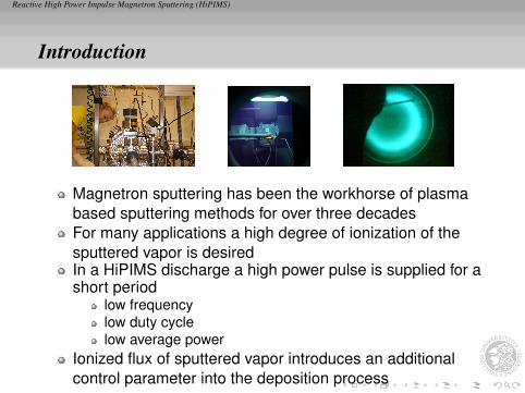
Magnetron sputtering has been the workhorse of plasmabased sputtering methods for over three decadesFor many applications a high degree of ionization of thesputtered vapor is desiredIn a HiPIMS discharge a high power pulse is supplied for ashort period
low frequencylow duty cyclelow average power
Ionized flux of sputtered vapor introduces an additionalcontrol parameter into the deposition process
Reactive High Power Impulse Magnetron Sputtering (HiPIMS)
Introduction
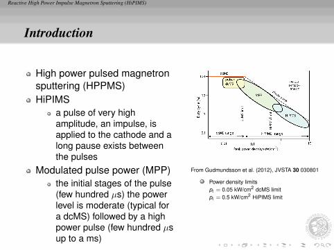
High power pulsed magnetronsputtering (HPPMS)HiPIMS
a pulse of very highamplitude, an impulse, isapplied to the cathode and along pause exists betweenthe pulses
Modulated pulse power (MPP)the initial stages of the pulse(few hundred µs) the powerlevel is moderate (typical fora dcMS) followed by a highpower pulse (few hundred µsup to a ms)
From Gudmundsson et al. (2012), JVSTA 30 030801
Power density limitspt = 0.05 kW/cm2 dcMS limitpt = 0.5 kW/cm2 HiPIMS limit
Reactive High Power Impulse Magnetron Sputtering (HiPIMS)
Reactive HiPIMS - Applications
Reactive High Power Impulse Magnetron Sputtering (HiPIMS)
Application – Film Resistivity
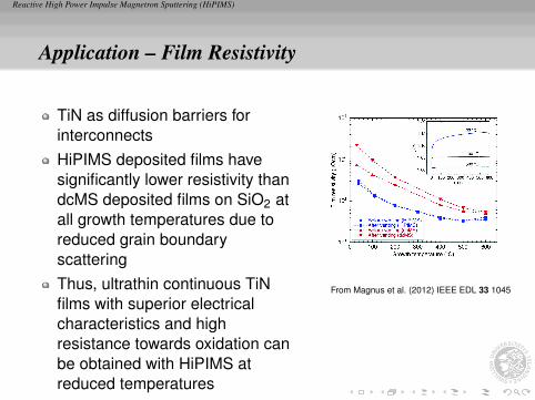
TiN as diffusion barriers forinterconnectsHiPIMS deposited films havesignificantly lower resistivity thandcMS deposited films on SiO2 atall growth temperatures due toreduced grain boundaryscatteringThus, ultrathin continuous TiNfilms with superior electricalcharacteristics and highresistance towards oxidation canbe obtained with HiPIMS atreduced temperatures
From Magnus et al. (2012) IEEE EDL 33 1045
Reactive High Power Impulse Magnetron Sputtering (HiPIMS)
Application – Bragg mirror
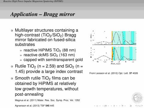
Multilayer structures containing ahigh-contrast (TiO2/SiO2) Braggmirror fabricated on fused-silicasubstrates
reactive HiPIMS TiO2 (88 nm)reactive dcMS SiO2 (163 nm)capped with semitransparent gold
Rutile TiO2 (n = 2.59) and SiO2 (n =1.45) provide a large index contrastSmooth rutile TiO2 films can beobtained by HiPIMS at relativelylow growth temperatures, withoutpost-annealingMagnus et al. (2011) Mater. Res. Soc. Symp. Proc. Vol. 1352
Agnarsson et al. (2013) TSF 545 445
From Leosson et al. (2012) Opt. Lett. 37 4026
Reactive High Power Impulse Magnetron Sputtering (HiPIMS)
Reactive HiPIMS - Voltage - Current - Timecharacteristics
Reactive High Power Impulse Magnetron Sputtering (HiPIMS)
HiPIMS - Voltage - Current - time
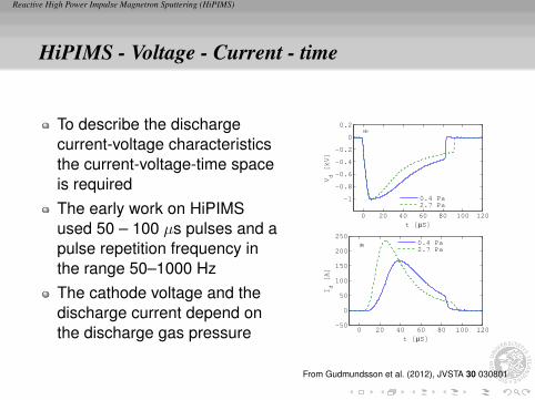
To describe the dischargecurrent-voltage characteristicsthe current-voltage-time spaceis requiredThe early work on HiPIMSused 50 – 100 µs pulses and apulse repetition frequency inthe range 50–1000 HzThe cathode voltage and thedischarge current depend onthe discharge gas pressure
0 20 40 60 80 100 120
−1
−0.8
−0.6
−0.4
−0.2
0
0.2
t [µS]
Vd [kV]
(a)
0.4 Pa
2.7 Pa
0 20 40 60 80 100 120−50
0
50
100
150
200
250
t [µS]
Id [A]
(b) 0.4 Pa
2.7 Pa
From Gudmundsson et al. (2012), JVSTA 30 030801
Reactive High Power Impulse Magnetron Sputtering (HiPIMS)
HiPIMS - Voltage - Current - time
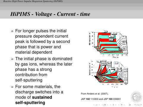
For longer pulses the initialpressure dependent currentpeak is followed by a secondphase that is power andmaterial dependentThe initial phase is dominatedby gas ions, whereas the laterphase has a strongcontribution fromself-sputteringFor some materials, thedischarge switches into amode of sustainedself-sputtering
From Anders et al. (2007),
JAP 102 113303 and JAP 103 039901
Reactive High Power Impulse Magnetron Sputtering (HiPIMS)
HiPIMS - Voltage - Current - time
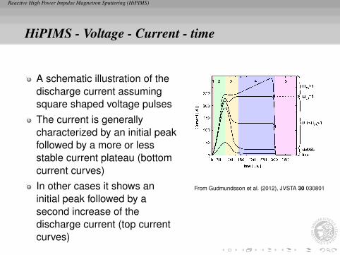
A schematic illustration of thedischarge current assumingsquare shaped voltage pulsesThe current is generallycharacterized by an initial peakfollowed by a more or lessstable current plateau (bottomcurrent curves)In other cases it shows aninitial peak followed by asecond increase of thedischarge current (top currentcurves)
From Gudmundsson et al. (2012), JVSTA 30 030801
Reactive High Power Impulse Magnetron Sputtering (HiPIMS)
HiPIMS - Voltage - Current - time
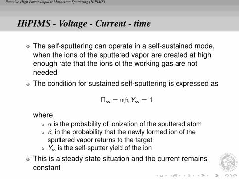
The self-sputtering can operate in a self-sustained mode,when the ions of the sputtered vapor are created at highenough rate that the ions of the working gas are notneededThe condition for sustained self-sputtering is expressed as
Πss = αβtYss = 1
whereα is the probability of ionization of the sputtered atomβt in the probability that the newly formed ion of thesputtered vapor returns to the targetYss is the self-sputter yield of the ion
This is a steady state situation and the current remainsconstant
Reactive High Power Impulse Magnetron Sputtering (HiPIMS)
HiPIMS - Voltage - Current - time
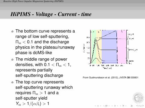
The bottom curve represents arange of low self-sputtering,Πss < 0.1 and the dischargephysics in the plateau/runawayphase is dcMS-likeThe middle range of powerdensities, with 0.1 < Πss < 1,represents partiallyself-sputtering dischargeThe top curve representsself-sputtering runaway whichrequires Πss > 1 and aself-sputter yieldYss > 1/(αβt) > 1
From Gudmundsson et al. (2012), JVSTA 30 030801
Reactive High Power Impulse Magnetron Sputtering (HiPIMS)
HiPIMS - Voltage - Current - time
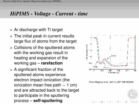
Ar discharge with Ti targetThe initial peak in current resultslarge flux of atoms from the targetCollisions of the sputtered atomswith the working gas result inheating and expansion of theworking gas – rarefactionA significant fraction of thesputtered atoms experienceelectron impact ionization (theionization mean free path ∼ 1 cm)and are attracted back to the targetto participate in the sputteringprocess – self-sputtering
From Magnus et al. (2011) JAP 110 083306
Reactive High Power Impulse Magnetron Sputtering (HiPIMS)
HiPIMS - Voltage - Current - time
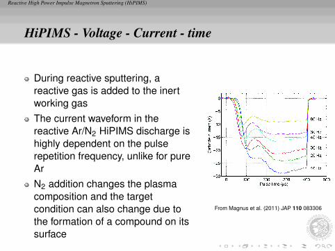
During reactive sputtering, areactive gas is added to the inertworking gasThe current waveform in thereactive Ar/N2 HiPIMS discharge ishighly dependent on the pulserepetition frequency, unlike for pureArN2 addition changes the plasmacomposition and the targetcondition can also change due tothe formation of a compound on itssurface
From Magnus et al. (2011) JAP 110 083306
Reactive High Power Impulse Magnetron Sputtering (HiPIMS)
HiPIMS - Voltage - Current - time
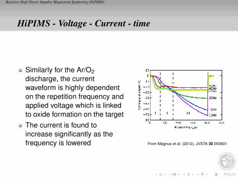
Similarly for the Ar/O2discharge, the currentwaveform is highly dependenton the repetition frequency andapplied voltage which is linkedto oxide formation on the targetThe current is found toincrease significantly as thefrequency is lowered From Magnus et al. (2012), JVSTA 30 050601
Reactive High Power Impulse Magnetron Sputtering (HiPIMS)
HiPIMS - Voltage - Current - time
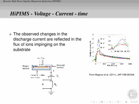
The observed changes in thedischarge current are reflected in theflux of ions impinging on thesubstrate
From Magnus et al. (2011), JAP 110 083306
Reactive High Power Impulse Magnetron Sputtering (HiPIMS)
HiPIMS - Voltage - Current - time
The discharge current Id is the sum of the ion current Ii andthe secondary electron current IiγSE or
Id = Ii(1 + γSE)
where γSE is the secondary electron emission coefficient ofthe target materialAlso
Ii ∝ ni ∝1ET
The total energy loss per electron-ion pair lost from thesystem ET is expected to increase with the addition ofnitrogenWe must turn to the secondary electron emission yield toexplain the self-sputtering runaway and observedfrequency dependence of the current in the reactivedischarge
Reactive High Power Impulse Magnetron Sputtering (HiPIMS)
HiPIMS - Voltage - Current - time
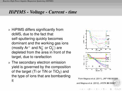
HiPIMS differs significantly fromdcMS, due to the fact thatself-sputtering quickly becomesdominant and the working gas ions(mostly Ar+ and N+
2 or O+2 ) are
depleted from the area in front of thetarget, due to rarefactionThe secondary electron emissionyield is governed by the compositionof the target (Ti or TiN or TiO2) andthe type of ions that are bombardingit
From Magnus et al. (2011), JAP 110 083306
and Magnus et al. (2012), JVSTA 30 050601
Reactive High Power Impulse Magnetron Sputtering (HiPIMS)
HiPIMS - Voltage - Current - time
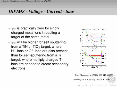
γSE is practically zero for singlycharged metal ions impacting atarget of the same metalγSE will be higher for self sputteringfrom a TiN or TiO2 target, whereN+-ions or O+-ions are also present,than for self-sputtering from a Titarget, where multiply charged Tiions are needed to create secondaryelectrons
From Magnus et al. (2011), JAP 110 083306
and Magnus et al. (2012), JVSTA 30 050601
Reactive High Power Impulse Magnetron Sputtering (HiPIMS)
HiPIMS - Voltage - Current - time
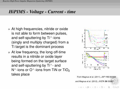
At high frequencies, nitride or oxideis not able to form between pulses,and self-sputtering by Ti+-ions(singly and multiply charged) from aTi target is the dominant processAt low frequency, the long off-timeresults in a nitride or oxide layerbeing formed on the target surfaceand self-sputtering by Ti+- andN+-ions or O+-ions from TiN or TiO2takes place
From Magnus et al. (2011), JAP 110 083306
and Magnus et al. (2012), JVSTA 30 050601
Reactive High Power Impulse Magnetron Sputtering (HiPIMS)
HiPIMS - Voltage - Current - time
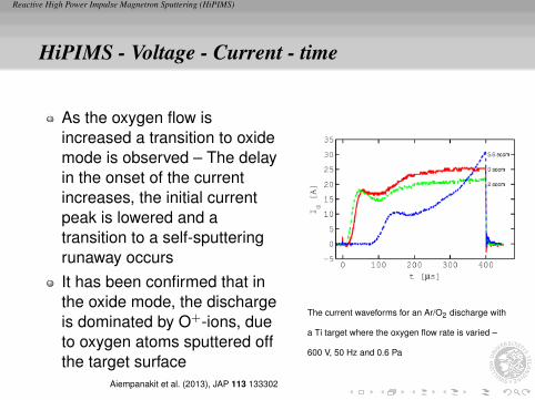
As the oxygen flow isincreased a transition to oxidemode is observed – The delayin the onset of the currentincreases, the initial currentpeak is lowered and atransition to a self-sputteringrunaway occursIt has been confirmed that inthe oxide mode, the dischargeis dominated by O+-ions, dueto oxygen atoms sputtered offthe target surface
Aiempanakit et al. (2013), JAP 113 133302
The current waveforms for an Ar/O2 discharge with
a Ti target where the oxygen flow rate is varied –
600 V, 50 Hz and 0.6 Pa
Reactive High Power Impulse Magnetron Sputtering (HiPIMS)
Summary
Reactive High Power Impulse Magnetron Sputtering (HiPIMS)
Summary
The current-voltage-time waveforms in a reactivedischarge exhibit similar general characteristics as thenon-reactive case
the current rises to a peak, then decays because ofrarefaction before rising to a self-sputtering dominatedphase
At low repetition frequency, the long off-time results in anitride or oxide layer being formed on the target surfaceand self-sputtering by Ti+ and N+ or O+-ions from TiN orTiO2 takes place with an increase in secondary electronemission yield and a corresponding increase in dischargecurrent
Reactive High Power Impulse Magnetron Sputtering (HiPIMS)
ReferencesThe slides can be downloaded athttp://langmuir.raunvis.hi.is/∼tumi/hipims.htmlAgnarsson, B., F. Magnus, T. K. Tryggvason, A. S. Ingason, K. Leosson, S. Olafsson, and J. T. Gudmundsson
(2013). Rutile TiO2 thin films grown by reactive high power impulse magnetron sputtering. Thin Solid Films 545,445–450.
Aiempanakit, M., A. Aijaz, D. Lundin, U. Helmersson, and T. Kubart (2013). Understanding the discharge currentbehavior in reactive high power impulse magnetron sputtering of oxides. Journal of Applied Physics 113(13),133302.
Anders, A., J. Andersson, and A. Ehiasarian (2007). High power impulse magnetron sputtering:Current-voltage-time characteristics indicate the onset of sustained self-sputtering. Journal of AppliedPhysics 102(11), 113303 and 103(3), 039901.
Gudmundsson, J. T., N. Brenning, D. Lundin, and U. Helmersson (2012). High power impulse magnetron sputteringdischarge. Journal of Vacuum Science and Technology A 30(3), 030801.
Leosson K., S. Shayestehaminzadeh, T. K. Tryggvason, A. Kossoy, B. Agnarsson, F. Magnus, S. Olafsson,J. T. Gudmundsson, E. B. Magnusson and I. A. Shelykh (2012). Optics Letters 37 (19), 4026 – 4028 .
Magnus, F., B. Agnarsson, A. S. Ingason, K. Leosson, S. Olafsson, and J. T. Gudmundsson (2011). Mater. Res.Soc. Symp. Proc. vol 1352
Magnus, F., O. B. Sveinsson, S. Olafsson, and J. T. Gudmundsson (2011). Current-voltage-time characteristics ofthe reactive Ar/N2 high power impulse magnetron sputtering discharge. Journal of Applied Physics 110(8),083306.
Magnus, F., A. S. Ingason, S. Olafsson, and J. T. Gudmundsson (2012). Nucleation and resistivity of ultrathin TiNfilms grown by high power impulse magnetron sputtering. IEEE Electron Device Letters 33(7), 1045 – 1047.
Magnus, F., T. K. Tryggvason, S. Olafsson, and J. T. Gudmundsson (2012). Current-voltage-time characteristics ofthe reactive Ar/O2 high power impulse magnetron sputtering discharge. Journal of Vacuum Science andTechnology A 30(5), 050601.


![[PPT]Home-Made DC Magnetron Sputtering System - …faculty.kfupm.edu.sa/.../research_files/magnetron.ppt · Web viewHome-Made DC Magnetron Sputtering System Chamber and Gas supply](https://img.dokumen.tips/doc/110x75/5aa9b1b37f8b9a90188d2f45/ppthome-made-dc-magnetron-sputtering-system-viewhome-made-dc-magnetron-sputtering.jpg)