Embed Size (px)
Citation preview

© 2007 Cisco Systems, Inc. All rights reserved. Cisco PublicPresentation_ID 1
Data Center ManagementHow Cisco IT Operates, Manages, and Protects Its Data Center
A Cisco on Cisco Case Study: Inside Cisco IT

© 2007 Cisco Systems, Inc. All rights reserved. Cisco PublicPresentation_ID 2
Overview
The Cisco® IT Operations Data Center on the San Jose, California campus is one of five Cisco production data centers worldwide
Supports Cisco’s intranet systems, enterprise resource planning (ERP) systems such as financials, data storage, IP telephony infrastructure, and a multitude of other employee-facing applications and databasesHouses the Operations Command Center (OCC), which monitors business-critical resources within Cisco data centers worldwideOccupies 14,269 square feet and consists of four areas:
Cisco IT OCC“Original” data center constructed in 1999Build room“Expanded” data center added in 2001

© 2007 Cisco Systems, Inc. All rights reserved. Cisco PublicPresentation_ID 3
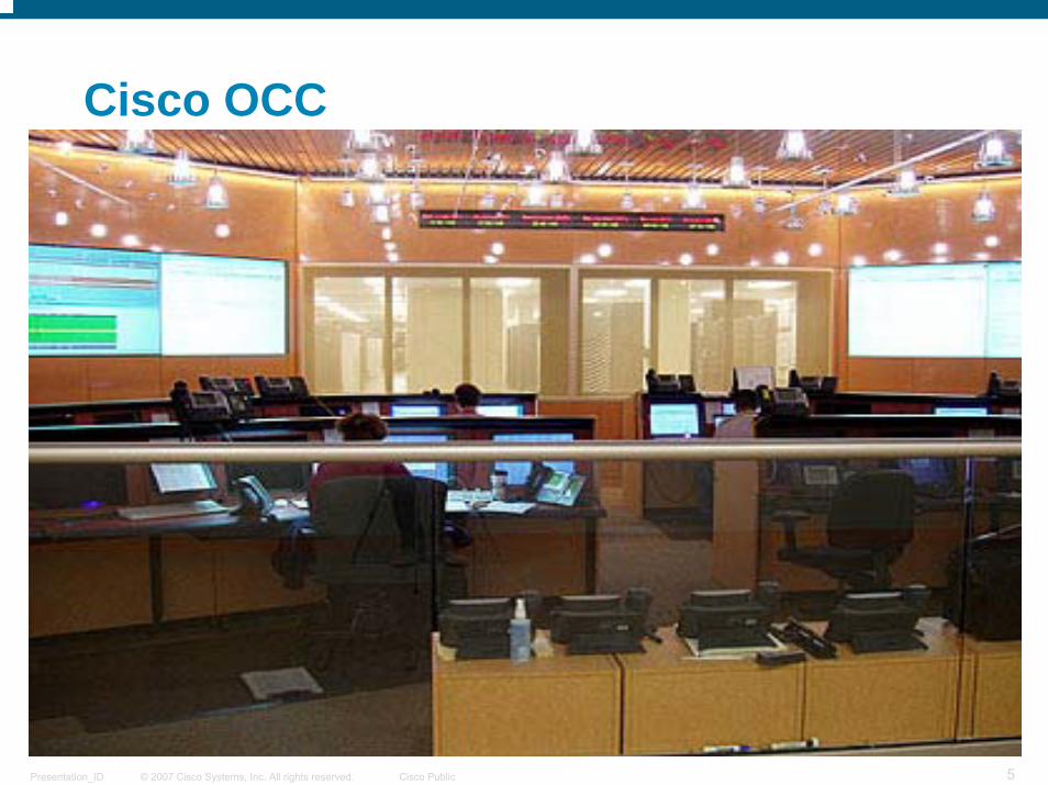
Cisco OCC
Facilitates problem resolution for significant failures that could affect business continuity
Tracks and responds to high-priority issues regarding priority-1 (P1) and priority-2 (P2) systems located in the five production and 41 engineering data centers worldwide
Monitors about 8000 P1 and P2 hosts, including switches, routers, and servers across all operating systems and architectures, in addition to 374 P1 applications and 500 P2 applications

© 2007 Cisco Systems, Inc. All rights reserved. Cisco PublicPresentation_ID 4
Cisco OCC (Contd.)
San Jose OCC staff monitors network 6 a.m. to 6 p.m. Pacific Time
Similar command center within Divyasree data center building in Bangalore, India, monitors network 6 p.m. to 6 a.m. Pacific Time
© 2007 Cisco Systems, Inc. All rights reserved. Cisco PublicPresentation_ID 5
Cisco OCC

© 2007 Cisco Systems, Inc. All rights reserved. Cisco PublicPresentation_ID 6
OCC Responsibilities
San Jose building 12 OCC staff provide communication, coordination, and documentation during incidents involving a P1 or P2 host or application
Communication ― Letting the right business or support groups know about the existence of a down or degraded resource
Coordination ― Getting all duty support responders required to identify and resolve a problem to talk together to keep the resolution process active
Documentation ― Capturing every detail of the incident, from a short-term fix to a full recovery, in real time

© 2007 Cisco Systems, Inc. All rights reserved. Cisco PublicPresentation_ID 7
OCC Monitoring
OCC uses the Enterprise Management (EMAN) monitoring tool to perform resource monitoring, automatic page alerting, change management tracking, and availability measurements
Sends out series of two “pings” every 15 seconds to 10,000+ resources it monitors 24 hours a day
If a resource fails to respond to one of these, EMAN reports a degraded service condition

© 2007 Cisco Systems, Inc. All rights reserved. Cisco PublicPresentation_ID 8
OCC Monitoring (Contd.)
If the resource fails to respond to these pings four times consecutively, EMAN reports zero percent availability—the resource is down
Failures associated with P1 and P2 resources are displayed in red on monitors within OCC

© 2007 Cisco Systems, Inc. All rights reserved. Cisco PublicPresentation_ID 9
OCC Monitoring (Contd.)

© 2007 Cisco Systems, Inc. All rights reserved. Cisco PublicPresentation_ID 10
Other OCC Responsibilities
EMAN supports change management, which is tightly integrated with the EMAN alerting process and availability monitoring
OCC monitors all approved change requests within their window of implementation—approximately 80 each day
OCC team also involved with month-end and quarter-end data processing, a large set of batch jobs run to close the monthly financial cycle
© 2007 Cisco Systems, Inc. All rights reserved. Cisco PublicPresentation_ID 11
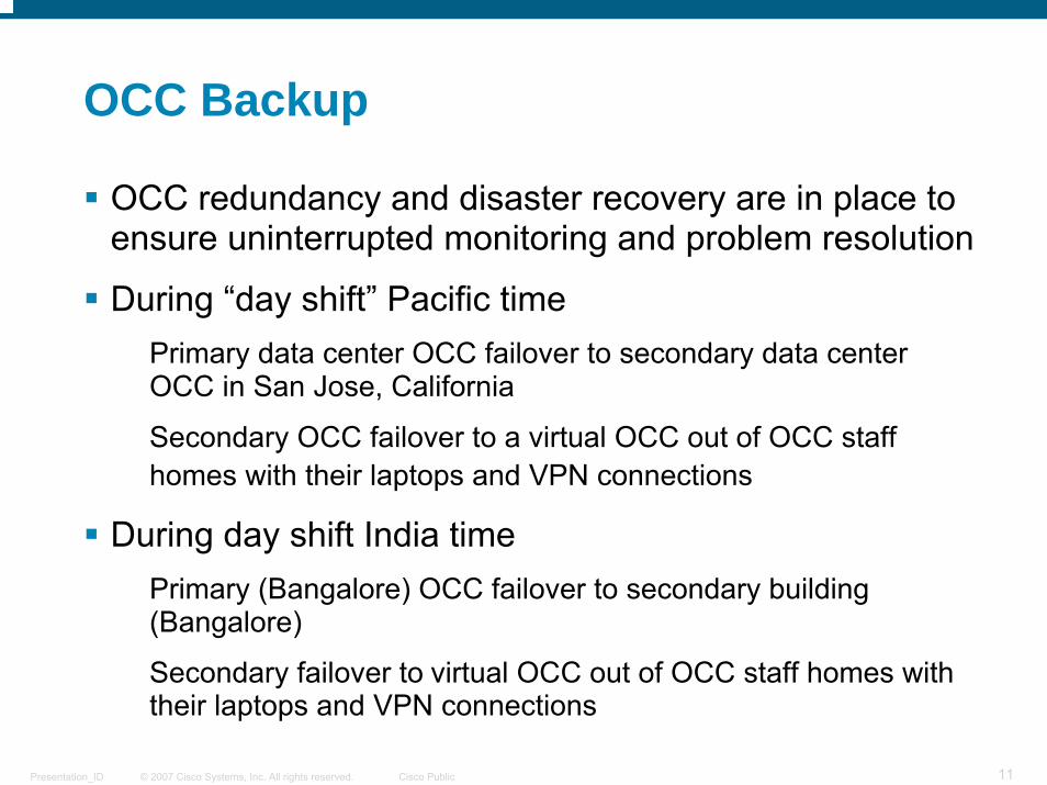
OCC Backup
OCC redundancy and disaster recovery are in place to ensure uninterrupted monitoring and problem resolution
During “day shift” Pacific timePrimary data center OCC failover to secondary data center OCC in San Jose, California
Secondary OCC failover to a virtual OCC out of OCC staff homes with their laptops and VPN connections
During day shift India timePrimary (Bangalore) OCC failover to secondary building (Bangalore)
Secondary failover to virtual OCC out of OCC staff homes with their laptops and VPN connections

© 2007 Cisco Systems, Inc. All rights reserved. Cisco PublicPresentation_ID 12
OCC Backup (Contd.)
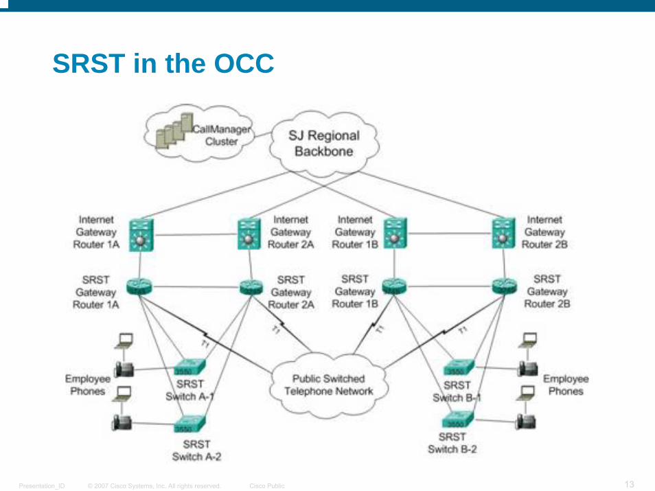
Failover capability and automatic reroute at OCC shift change made possible through IP telephony infrastructure built on Cisco® AVVID (Architecture for Voice, Video and Integrated Data) technology
IP telephony service within the two San Jose OCCs has been equipped with Survivable Remote Site Telephony (SRST) to provide disaster recovery
For data, a disaster in the San Jose building 12 data center would initiate a failover to Research Triangle Park, North Carolina, where all backup ERP and Cisco.com applications and data are stored
© 2007 Cisco Systems, Inc. All rights reserved. Cisco PublicPresentation_ID 13
SRST in the OCC

© 2007 Cisco Systems, Inc. All rights reserved. Cisco PublicPresentation_ID 14
Build Room
Build room provides an area for equipment vendors to rack, stack, configure, and burn in new systems before they go into production and try new equipment and configurations
Cabling and network architecture in the Build room is designed to flexibly support quick equipment changes
Network cabinet in every half row of each of four rows makes connecting and reconnecting new equipment and moving equipment much easier by not having to pull new cable the length of the room

© 2007 Cisco Systems, Inc. All rights reserved. Cisco PublicPresentation_ID 15
Build Room (Contd.)
Cisco® Catalyst® 6500 Series Switch within network cabinet in each half-row of the Build room
Cisco Catalyst 6500 Series used in all Cisco IT data centers to connect data center resources to the desktop LAN
Cisco 3600 Series Router also in each network cabinet
© 2007 Cisco Systems, Inc. All rights reserved. Cisco PublicPresentation_ID 16
Build Room (Contd.)
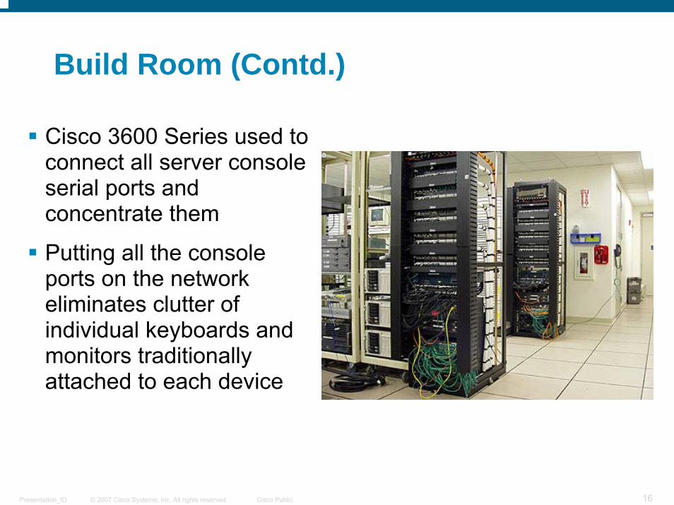
Cisco 3600 Series used to connect all server console serial ports and concentrate them
Putting all the console ports on the network eliminates clutter of individual keyboards and monitors traditionally attached to each device

© 2007 Cisco Systems, Inc. All rights reserved. Cisco PublicPresentation_ID 17
Build Room (Contd.)
Standardized cabling system in Build room
Cable breakout box under each floor tile connected to 12 or 24 fibers and clearly labeled with port numbers

© 2007 Cisco Systems, Inc. All rights reserved. Cisco PublicPresentation_ID 18
Build Room (Contd.)
Connecting a new device is as easy as dropping a patch cable to the breakout box, going to the zonal cabinet—which is clearly labeled with the row, breakout box, and port—and plugging that into Cisco® Catalyst®6500 Series Switch
Engineers no longer must pull a series of floor tiles or cables

© 2007 Cisco Systems, Inc. All rights reserved. Cisco PublicPresentation_ID 19
Data Center
Equipment within the data center, as in the other four production data centers, is largely supported directly by vendors under contract with Cisco ITVendors perform upgrades, changes, and troubleshooting and repair if a problem arises with equipmentBecause support contracts stipulate that equipment is to be left in its vendor state of packaging, much of the equipment is installed with its original cabinetry rather than in standard engineering racksSan Jose building 12 production data center uses a single rack of network equipment at the end of the data center, unlike the Build room where a network rack is situated at the end of every half-row

© 2007 Cisco Systems, Inc. All rights reserved. Cisco PublicPresentation_ID 20
Data Center – Vendor Access
Modems Many of the storage frames have modem boxes to allow vendors to remotely monitor their equipment
If a device experiences a problem, it automatically calls the vendor
Vendor can then dial in through the same modem and diagnose the problem
Analog modems will soon be replaced by a VPN solution over the Cisco® IP network and the Internet

© 2007 Cisco Systems, Inc. All rights reserved. Cisco PublicPresentation_ID 21
Data Center Storage
StorageSan Jose building 12 data center contains about 800 terabytes ofstorage
Nearly all frames connected directly to each host until 2002
Connecting two or three hosts to a storage frame was inefficient, causing storage frames to be underutilized
Now, hundreds of hosts are connected to a group of storage frames through a Storage Area Network (SAN), creating a large, efficient pool of shared storage supported by Cisco® MDS 9509 multilayer director switches
San Jose building 12 data center also provides tape storage for vital records, however, backup storage for San Jose is in the RTP datacenter, which acts as a hot standby site

© 2007 Cisco Systems, Inc. All rights reserved. Cisco PublicPresentation_ID 22
Data Center Servers
ServersSan Jose building 12 data center houses many servers in distributed environments that can be stacked and pooled togetherMost run Linux and Windows OSsSome are large, supporting multiple e-commerce applicationsOthers are smaller and highly specialized, such as the five Cisco® CallManagers, taking up a quarter rack, that replaced a PBX in each of the 51 San Jose campus buildings

© 2007 Cisco Systems, Inc. All rights reserved. Cisco PublicPresentation_ID 23
Data Center Cabling
Cabling Beneath the Raised FloorCable layout under the raised floor in the San Jose building 12 data center and other production data centers has been standardized
Network cables rest in suspended trays closest to the raised tiles
Power cables located near the concrete floor
Provides vertical separation from the network cabling
Horizontal separation created by running network cabling beneath one row of tiles and power beneath another row in each aisle
Copper grounding wire closest to the concrete floor arranged in a two-foot grid pattern throughout the data center

© 2007 Cisco Systems, Inc. All rights reserved. Cisco PublicPresentation_ID 24
Data Center Cabling (continued)

© 2007 Cisco Systems, Inc. All rights reserved. Cisco PublicPresentation_ID 25
Data Center – Fire Suppression
Fire SuppressionTwo forms of fire protection, FM200 and water, are activated in stages within the San Jose building 12 data center
Smoke detection by one of many sensors mounted in the ceiling throughout the data center sets off an alarm, which dispatches Cisco® security
Smoke detection by two sensors begins a 30-second countdown. FM200 will discharge throughout data center unless a technician in the area presses one of the designated panels on the wall to suspend the countdown
When FM200 is released, dry sprinkler pipes fill with water and sufficiently hot fire beneath one or more of the sprinklers will trigger the release of water in area of fire
Smoke Sensor
Water and FM200
Nozzles

© 2007 Cisco Systems, Inc. All rights reserved. Cisco PublicPresentation_ID 26
Data Center – Earthquake Protection
Earthquake ProtectionSeismic isolation platforms in the main San Jose production data center allow equipment to survive an 8.3 earthquake with little or no damage
Platforms contain two parabolic plates with a large ball bearingin between them
Hosts or frames are fastened to the upper seismic plate with nylon straps, which allows the upper portion of the platform to remain relatively stationary while the lower portion and ground move side to side in an earthquake
Extra slack in cabling prevents disconnection in all but the largest tremors

© 2007 Cisco Systems, Inc. All rights reserved. Cisco PublicPresentation_ID 27
Data Center – Earthquake Protection (Contd.)

© 2007 Cisco Systems, Inc. All rights reserved. Cisco PublicPresentation_ID 28
Data Center – Temperature Sensing
Temperature Sensing SystemConcerned with temperature at the frame or host, Cisco® placed temperature sensors in many of the racks and frames, distributed in a grid-like pattern
Sensors connect to an IP-based console network for remote monitoring
Alarm is sent to OCC if temperature at any sensor exceeds threshold
Sensors have eliminated two or three temperature-related system problems a year
TemperatureSensor

© 2007 Cisco Systems, Inc. All rights reserved. Cisco PublicPresentation_ID 29
Data Center – Power Distribution
Power DistributionHosts getting smaller, increasing power drops per rack, and many require redundant power supplies, separate power drops, or both to the same device, putting strain on power distribution system
In newer section of San Jose building 12 data center, three power distribution unit (PDU) cabinets deployed
Drops run from each PDU to three circuit breaker distribution cabinets in each row
Physical circuits run under the floor to each frame, supplying ample connections for power drops and separate power sources for power redundancy where required

© 2007 Cisco Systems, Inc. All rights reserved. Cisco PublicPresentation_ID 30
Data Center – Power Backup
Power Backup and UPSUninterruptible power supply (UPS) system and dual backup generators provide continuous power to data center in the event of power failure
Power flows from the power grid through UPS system, providing the data center with filtered power during normal operation
If grid power lost, battery power from UPS system supports entire data center for up to 20 minutes
Cisco® maintains three UPS systems, but only two are needed to support full design load of data center, providing N+1 redundancy

© 2007 Cisco Systems, Inc. All rights reserved. Cisco PublicPresentation_ID 31
Data Center – Power Backup (Contd.)
Power Backup and GeneratorsWhen power is lost, two backup diesel generators
begin to spin-up to full power within 20 seconds
When fully running and synchronized, generator power is sent through the UPS system, which also recharges the UPS batteries
One generator is sufficient to supply the load for the entire data center, but a second generator provides backup
Because it can be difficult to determine the state of the power supply (grid, UPS, or generator) two lights were installed in the data center: Red for UPS, blue for generator
An IP closed-circuit camera allows the OCC to monitor the lights remotely

© 2007 Cisco Systems, Inc. All rights reserved. Cisco PublicPresentation_ID 32
To read the entire case study, or for additional Cisco IT case studies on a variety of business solutions, visit Cisco on Cisco: Inside Cisco IT
www.cisco.com/go/ciscoit