Embed Size (px)
Citation preview
High Voltage Engineering
Course Code: EE 2316
10/7/2017 Prof. Dr. Magdi El-Saadawi 1
Prof. Dr. Magdi M. El-Saadawi
www.saadawi1.net
E-mail : [email protected]
www.facebook.com/magdi.saadawi
ContentsChapter 1
Introduction to High Voltage Technology
Chapter 2
Generation of High Voltages and Currents
Chapter 3
Measurement of High Voltages and Currents
Chapter 4
Breakdown Mechanism of Gases, Liquid and
Solid Materials210/7/2017
Chapter 2
Generation of High Voltages and Currents
2.1. Introduction
2.2. Generation of High D.C. Voltages2.2.1 Half-Wave Rectifier Circuit
2.2.2 Cascade circuits
2.2.3 Electrostatic Generators
2.3. Generation of High A.C. Voltages2.3.1 Cascaded Transformers
2.3.2 Series Resonant Circuit
2.4. Generation of Impulse Voltages and Currents2.4.1 Impulse Generator Circuits
2.4.2 Multistage Impulse Generator Circuit
2.4.3 Components of a Multistage Impulse Generator
2.5. Solved Examples310/7/2017 Prof. Dr. Magdi El-Saadawi
10/7/2017 4
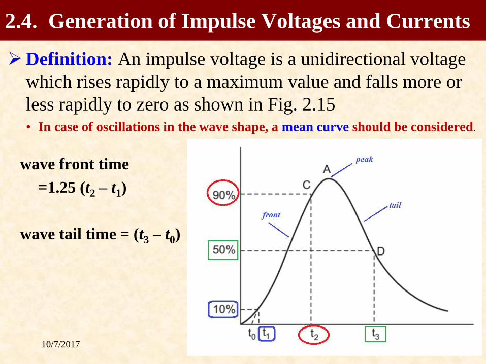
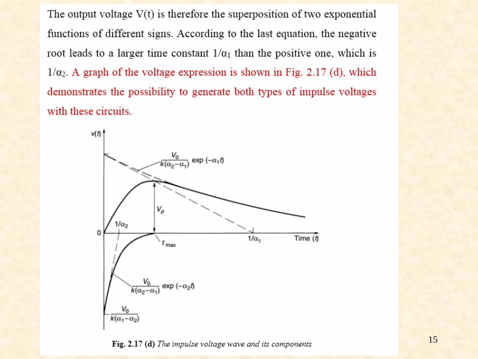
➢Definition: An impulse voltage is a unidirectional voltage
which rises rapidly to a maximum value and falls more or
less rapidly to zero as shown in Fig. 2.15• In case of oscillations in the wave shape, a mean curve should be considered.
wave front time
=1.25 (t2 – t1)
wave tail time = (t3 – t0)
Prof. Dr. Magdi El-Saadawi
2.4. Generation of Impulse Voltages and Currents

10/7/2017 5
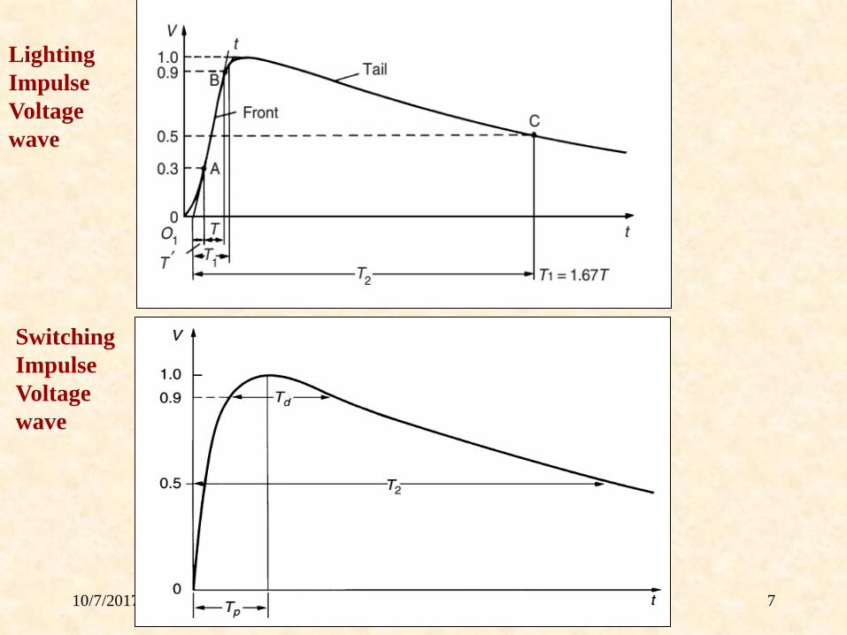
– The wave front is the average rate of rise of voltage between
the points where the voltage is 10% and 90% of the peak value.
Lighting Impulse Voltage wave
– The standard wave shape specified in BSS and ISS is
1/50 micro sec. wave
a wave front of 1 micro sec. + 50%
a wave tail of 50 micro sec. + 20%
– 100 kV, 1/50 micro sec. wave means that peak value of 100 kV
– The wave shape recommended by the American Standard
Association is 1.5/40 micro sec.
– Here wave front time is taken as 1.67 times the time taken by the
wave to rise from 30% to 90% of its peak value and wave tail time
is computed as in BSS or ISS i.e. it is given as (t3 – t0)
2.4. Generation of Impulse Voltages and Currents
10/7/2017 6
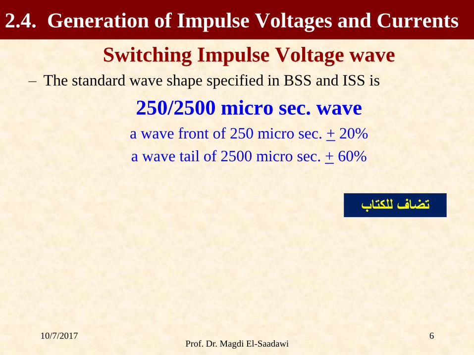
Switching Impulse Voltage wave
– The standard wave shape specified in BSS and ISS is
250/2500 micro sec. wave
a wave front of 250 micro sec. + 20%
a wave tail of 2500 micro sec. + 60%
Prof. Dr. Magdi El-Saadawi
2.4. Generation of Impulse Voltages and Currents
تضاف للكتاب
10/7/2017 Prof. Dr. Magdi El-Saadawi 7
Lighting
Impulse
Voltage
wave
Switching
Impulse
Voltage
wave
10/7/2017 8
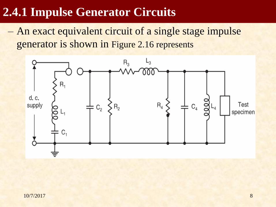
– An exact equivalent circuit of a single stage impulse
generator is shown in Figure 2.16 represents
2.4.1 Impulse Generator Circuits

10/7/2017 9
➢C1 capacitance of a d.c generator
➢L1 inductance of the generator and the leads connecting the
generator to the discharge circuit.
➢R1 inherent series resistance of the capacitances and leads
and often includes additional lumped resistance for output
waveform control.
➢L3, R3 are the external elements which may be connected at
the generator terminal for waveform control.
➢R2 and R4 control the duration of the wave.
R4 also serves as a potential divider when a CRO is used
for measurement purposes.
2.4.1 Impulse Generator Circuits
10/7/2017 10
➢C2 and C4 represent the capacitances to earth of the high
voltage components and leads.
C4 also includes the capacitance of the test object and of
any other load capacitance.
➢L4 represents the inductance of the test object and may also
affect the wave shape appreciably.
➢Usually for practical reasons, one terminal of the impulse
generator is solidly grounded. The polarity of the output
voltage can be changed by changing the polarity of the d.c.
charging voltage
2.4.1 Impulse Generator Circuits
10/7/2017 11
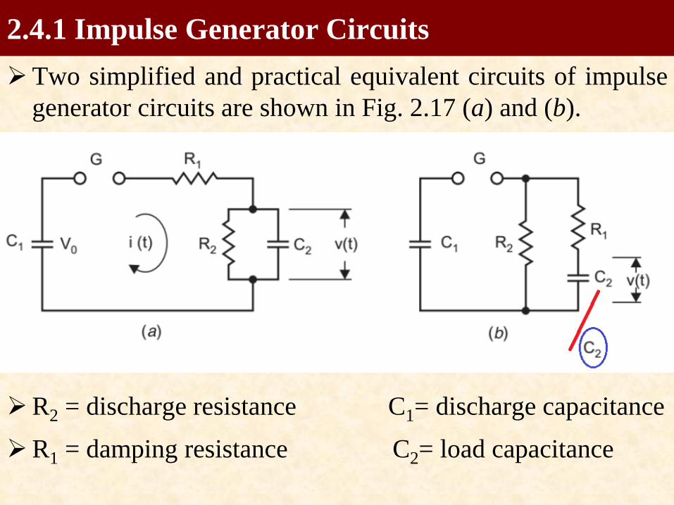
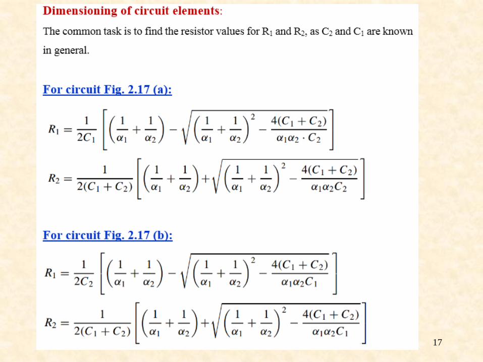
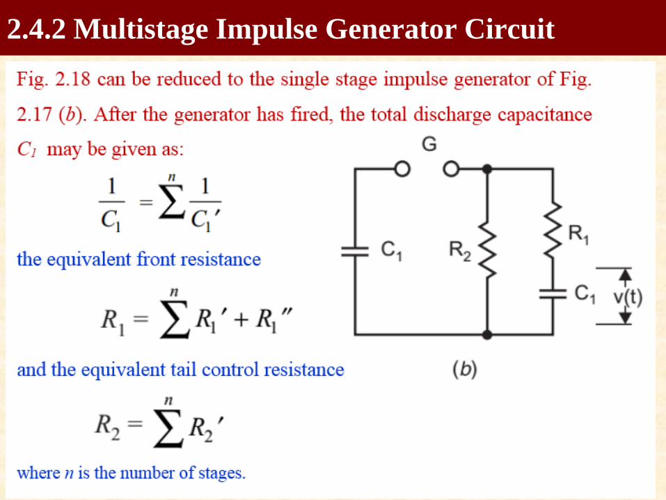
➢Two simplified and practical equivalent circuits of impulse
generator circuits are shown in Fig. 2.17 (a) and (b).
➢R2 = discharge resistance C1= discharge capacitance
➢R1 = damping resistance C2= load capacitance
2.4.1 Impulse Generator Circuits
10/7/2017 12
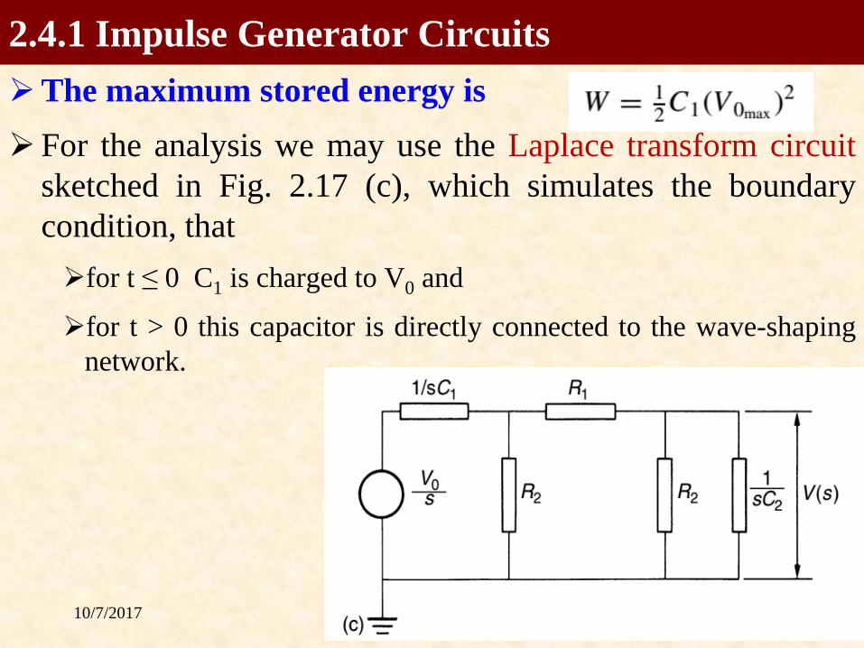
➢The maximum stored energy is
➢ For the analysis we may use the Laplace transform circuit
sketched in Fig. 2.17 (c), which simulates the boundary
condition, that
➢for t ≤ 0 C1 is charged to V0 and
➢for t > 0 this capacitor is directly connected to the wave-shaping
network.
2.4.1 Impulse Generator Circuits
10/7/2017 13
10/7/2017 14
10/7/2017 Prof. Dr. Magdi El-Saadawi 15

10/7/2017 Prof. Dr. Magdi El-Saadawi 16
10/7/2017 Prof. Dr. Magdi El-Saadawi 17
10/7/2017 Prof. Dr. Magdi El-Saadawi 18
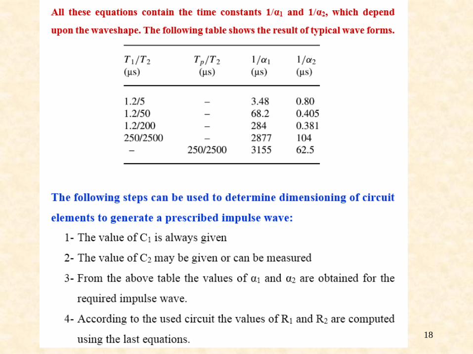
10/7/2017 19
• A single stage circuit is inconvenient to obtain
higher and higher impulse voltage because:(i) The physical size of the circuit elements becomes very large.
(ii) High d.c. charging voltage is required.
(iii) Suppression of corona discharges from the structure and leads
during the charging period is difficult.
(iv) Switching of vary high voltages with spark gaps is difficult.
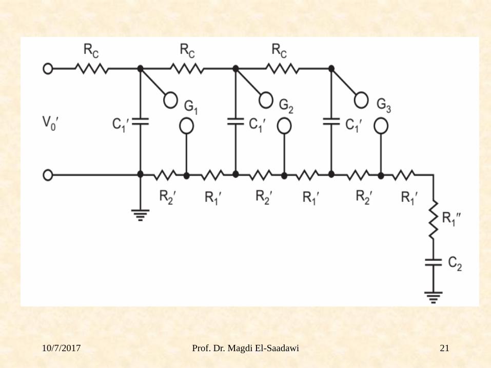
2.4.2 Multistage Impulse Generator Circuit

10/7/2017 20
Fig. 2.18 shows a 3-stage impulse generator circuit due to
Marx employing ‘b’ circuit connections.
➢ The impulse capacitors C1 are charged to the charging
voltage V0 through the high charging resistors Rc in
parallel.
➢ When all the gaps G break down, the C1 capacitances are
connected in series so that C2 is charged through the series
connection of all the wave front resistances R1 and finally
all C1 and C2 will discharge
➢ Usually Rc >> R2 >> R1.
➢ If in Fig. 2.18 the wave tail resistors R2 in each stage are
connected in parallel to the series combination of R1 , G
and C1 , an impulse generator of type ‘a’ is obtained.
2.4.2 Multistage Impulse Generator Circuit
10/7/2017 Prof. Dr. Magdi El-Saadawi 21
10/7/2017 22
2.4.2 Multistage Impulse Generator Circuit
10/7/2017 23
(i) d.c. Charging Set
The charging unit should be capable of giving a
variable d.c. voltage of either polarity to charge the
generator capacitors to the required value.
(ii) Charging Resistors
These will be non-inductive high value resistors of
about 10 to 100 kilo-ohms. Each resistor will be
designed to have a maximum voltage between 50
and 100kV.
2.4.3 Components of a Multistage Impulse Generator

10/7/2017 24
(iii) Generator Capacitors and Spark Gaps
These are arranged vertically one over the other with
all the spark gaps aligned. The capacitors are
designed for several charging and discharging
operations.
On dead short circuit, the capacitors will be capable
of giving 10 kA of current.
The spark gaps will be usually spheres or
hemispheres of 10 to 25 cm diameter. Sometimes
spherical ended cylinders with a central support may
also be used.
2.4.3 Components of a Multistage Impulse Generator
10/7/2017 25
(iv) Wave-shaping Resistors and Capacitors
Resistors will be non-inductive wound type and
should be capable of discharging impulse currents of
1000 A or more.
Each resistor will be designed for a maximum
voltage of 50 to 100 kV. The resistances are bifilar
wound or non-inductive thin flat insulating sheets.
In some cases, they are wound on thin cylindrical
formers and are completely enclosed. The load
capacitor may be of compressed gas or oil filled with
a capacitance of 1to10 μF.
2.4.3 Components of a Multistage Impulse Generator

10/7/2017 26
(v) Triggering System
This consists of trigger إثارة أو اشعال spark gaps to cause
spark breakdown of the gaps
A simple method of controlled tripping consists of
making the first gap a three
electrode gap and firing it from a controlled source.
(vi) Voltage Dividers
Voltage dividers of either damped capacitor or
resistor type and an oscilloscope with recording
arrangement are provided for measurement of the
voltages across the test object.
2.4.3 Components of a Multistage Impulse Generator
10/7/2017 Prof. Dr. Magdi El-Saadawi 27
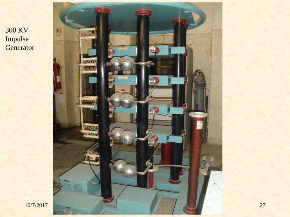
300 KV
Impulse
Generator
10/7/2017 Prof. Dr. Magdi El-Saadawi 28
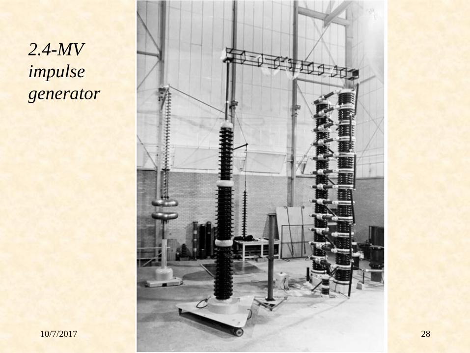
2.4-MV
impulse
generator
10/7/2017 Prof. Dr. Magdi El-Saadawi 29
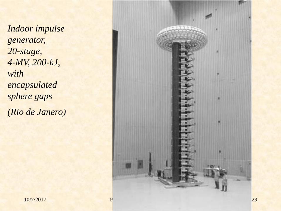
Indoor impulse
generator,
20-stage,
4-MV, 200-kJ,
with
encapsulated
sphere gaps
(Rio de Janero)
10/7/2017 Prof. Dr. Magdi El-Saadawi 30
Video Link
https://www.youtube.com/watch?v=IrQsghadA8A
10/7/2017 Prof. Dr. Magdi El-Saadawi 31