Embed Size (px)
Citation preview
52
Chapter 3 Electric Supply Systems
3.1 Introduction
Electric power is produced at the power stations which are
located at favorable places, generally quite away from the
consumers. It is then transmitted over large distances to load
centers with the help of conductors known as transmission
lines. Finally, it is distributed to a large number of small and
big consumers through a distribution network. In this chapter
we will focus on the various aspects of transmission of electric
power.
The electric supply system can be broadly classified into:
(i) d.c. or a.c. system,
(ii) overhead or underground system.
Nowadays, 3-phase, 3-wire a.c. system is universally adopted
for generation and transmission of electric power as an
economical proposition. However, distribution of electric
power is done by 3-phase, 4-wire a.c. system. The underground
system is more expensive than the overhead system. Therefore,
in Egypt, overhead system is mostly adopted for transmission
and distribution of electric power.
53
3.2 Typical A.C. Power Supply Scheme
The large network of conductors between the power station and
the consumers can be broadly divided into two parts:
transmission system and distribution system. Each part can be
further sub-divided into two: primary transmission and
secondary transmission and primary distribution and secondary
distribution. Fig. 3.1 shows the layout of a typical a.c. power
supply scheme by a single line diagram. It may be noted that it
is not necessary that all power schemes include all the stages
shown in the figure. For example, in a certain power scheme,
there may be no secondary transmission and in another case,
the scheme may be so small that there is only distribution and
no transmission.
(i) Generating station:
In Fig 3.1, G.S. represents the generating station where electric
power is produced by 3-phase alternators operating in parallel.
The usual generation voltage is 11 kV. For economy in the
transmission of electric power, the generation voltage (i.e., 11
kV) is stepped up to 132 kV (or more Depending upon the
length of transmission line and the amount of power to be
transmitted) at the generating station with the help of 3-phase
transformers. The transmission of electric power at high
voltages has several advantages including the saving of
conductor material and high transmission efficiency. It may
appear advisable to use the highest possible voltage for

54
transmission of electric power to save conductor material and
have other advantages. But there is a limit to which this voltage
can be increased. It is because increase in transmission voltage
introduces insulation problems as well as the cost of switchgear
and transformer equipment is increased. Therefore, the choice
of proper transmission voltage is essentially a question of
economics. Generally the primary transmission in Egypt is
carried at 66 kV, 132 kV, 220 kV or 500 kV.
(ii) Primary transmission.
The electric power at 132 kV is transmitted by 3-phase, 3-wire
overhead system to the outskirts الى مشارف of the city. This forms
the primary transmission.
(iii) Secondary transmission.
The primary transmission line terminates at the receiving
station (RS) which usually lies at the outskirts of the city. At
the receiving station, the voltage is reduced to 33 kV by step-
down transformers. From this station, electric power is
transmitted at 33 kV by 3-phase, 3-wire over head system to
various sub-stations (SS) located at the strategic points in the
city. This forms the secondary transmission. It may be
worthwhile to mention here that secondary distribution system
consists of feeders, distributors and service mains.
Fig. 3.2 shows the elements of low voltage distribution system.
Feeders (SC or SA) radiating from the distribution sub-station

55
(DS) supply power to the distributors (AB, BC, CD and AD).
No consumer is given direct connection from the feeders.
Instead, the consumers are connected to the distributors
through their service mains.
(iv) Primary distribution:
The secondary transmission line terminates at the sub-station
(SS) where voltage is reduced from 33 kV to 11kV, 3-phase, 3-
wire. The 11 kV lines run along the important road sides of the
city. This forms the primary distribution. It may be noted that
big consumers (having demand more than 50 kW) are
generally supplied power at 11 kV for further handling with
their own sub-stations.
(v) Secondary distribution.
The electric power from primary distribution line (11 kV) is
delivered to distribution sub-stations (DS). These sub-stations
are located near the consumers’ localities and step down the
voltage to 400 V, 3-phase, 4-wire for secondary distribution.
The voltage between any two phases is 400 V and between any
phase and neutral is 230 V. The single-phase residential
lighting load is connected between any one phase and neutral,
whereas 3-phase, 400 V motor load is connected across 3-
phase lines directly.

56

57
Fig. 3.1 Fig. 3.2
Note:
A practical power system has a large number of auxiliary
equipments (e.g., fuses, circuit breakers, voltage control
devices etc).
However, such equipments are not shown in Fig. 3.1. It is
because the amount of information included in the diagram
depends on the purpose for which the diagram is intended.
Here our purpose is to display general layout of the power
system. Therefore, the location of circuit breakers, relays etc.,
is unimportant.
Further, the structure of power system is shown by a single line
diagram. The complete 3-phase circuit is seldom necessary to
convey even the most detailed information about the system.
3.3 Comparison between D.C. and A.C. Transmission
The electric power can be transmitted either by means of d.c.
or a.c. Each system has its own merits and demerits. It is,
therefore, desirable to discuss the technical advantages and
disadvantages of the two systems for transmitting electric
power.
1. D.C. transmission.
For some years past, the transmission of electric power by d.c.
has been receiving the active consideration of engineers due to
its numerous advantages.

58
Advantages: The high voltage d.c. transmission has the
following advantages over high voltage a.c. transmission
1. It requires only two conductors as compared to three for
a.c. transmission.
2. There is no inductance, capacitance, phase displacement
and surge problems in d.c. transmission.
3. Due to the absence of inductance, the voltage drop in a d.c.
transmission line is less than the a.c. line for the same load
and sending end voltage. For this reason, a d.c.
transmission line has better voltage regulation.
4. There is no skin effect in a d.c. system. Therefore, entire
cross-section of the line conductor is utilized.
5. For the same working voltage, the potential stress on the
insulation is less in case of d.c. system than that in a.c.
system. Therefore, a d.c. line requires less insulation.
6. A d.c. line has lesser interference with communication
circuits.
Disadvantages
1. Electric power cannot be generated at high d.c. voltage
due to commutation problems.
2. The d.c. voltage cannot be stepped up for transmission of
power at high voltages.
3. The d.c. switches and circuit breakers have their own
limitations.
2. A.C. transmission.
59
Nowadays, electrical energy is almost exclusively generated,
transmitted and distributed in the form of a.c.
Advantages
1. The power can be generated at high voltages.
2. The maintenance of a.c. sub-stations is easy and cheaper.
3. The a.c. voltage can be stepped up or stepped down by
transformers with ease and efficiency. This permits to
transmit power at high voltages and distribute it at safe
potentials.
Disadvantages
1. An a.c. line requires more copper than a d.c. line.
2. The construction of a.c. transmission line is more
complicated than a d.c. transmission line.
3. Due to skin effect in the a.c. system, the effective
resistance of the line is increased.
4. An a.c. line has capacitance. Therefore, there is a
continuous loss of power due to charging current even
when the line is open.
Conclusion:
From the above comparison, it is clear that: high voltage d.c.
transmission is superior to high voltage a.c. transmission.
Although at present, transmission of electric power is carried
by a.c., there is an increasing interest in d.c and power
electronic devices have made it possible to convert a.c. into d.c.
transmission. Such devices can operate up to 30 MW at 400 kV

60
in single units. The present day trend is towards a.c. for
generation and distribution and high voltage d.c. for
transmission.
Fig. 3.3 shows the single line diagram of high voltage d.c.
transmission. The electric power is generated as a.c. and is
stepped up to high voltage by the sending end transformer TS.
The a.c. power at high voltage is fed to an a.c./d.c. converter
which convert a.c. into d.c. The transmission of electric power
is carried at high d.c. voltage. At the receiving end, d.c. is
converted into a.c. with the help of a d.c./a.c. converter. The
a.c. supply is stepped down to low voltage by receiving end
transformer TR for distribution.
Fig. 3.3
3.4 Advantages of High Transmission Voltage
The transmission of electric power is carried at high voltages
due to the following reasons:
(i) Reduces volume of conductor material.
Consider the transmission of electric power by a three-phase
line.

61
Let P = power transmitted in watts
V = line voltage in volts
cos φ = power factor of the load
l = length of the line in metres
R = resistance per conductor in ohms
ρ = resistivity of conductor material in ohms metre
a = area of X-section of conductor in sq. metres.
It is clear from the last equation that for given values of P, l, ρ
and W, the volume of conductor material required is inversely
proportional to the square of transmission voltage and power

62
factor. In other words, the greater the transmission voltage,
the lesser is the conductor material required.
(ii) Increases transmission efficiency
𝑷𝒐𝒘𝒆𝒓 𝑳𝒐𝒔𝒔𝒆𝒔 = 𝟑𝑰𝟐𝑹 = 𝟑𝑷𝟐
𝟑 𝑽𝟐𝒄𝒐𝒔𝟐 ∅×𝝆𝒍
𝒂=
𝑷𝟐𝝆𝒍
𝑽𝟐𝒂 𝒄𝒐𝒔𝟐 ∅
Increasing the transmission voltage will reduce the power
losses and hence increasing transmission efficiency
(iii) Decreases percentage line drop
𝑽𝒐𝒍𝒕𝒂𝒈𝒆 𝒍𝒊𝒏𝒆 𝒅𝒓𝒐𝒑 = 𝑰 𝑹 =𝑷 𝝆𝒍
𝑽 × 𝟑 𝒂 𝒄𝒐𝒔 ∅
From the last equation we can observe that increasing the
transmission voltage will reduce the power voltage line drop.
3.4.1 Limitations of high transmission voltage.
From the above discussion, it might appear advisable to use the
highest possible voltage for transmission of power in order to
save conductor material.
However, it must be realized that high transmission voltage
results in:
(i) the increased cost of insulating the conductors
(ii) the increased cost of transformers, switchgear and
other terminal apparatus.
Therefore, there is a limit to the higher transmission voltage
which can be economically employed in a particular case.

63
This limit is reached when the saving in cost of conductor
material due to higher voltage is offset by the increased cost of
insulation, transformer, switchgear etc. Hence, the choice of
proper transmission voltage is essentially a question of
economics. Further discussion on this topic will be discussed
later in this chapter.
3.5 Various Systems of Power Transmission
It has already been pointed out that for transmission of electric
power, 3-phase, 3-wire a.c. system is universally adopted.
However, other systems can also be used for transmission
under special circumstances. The main systems used in
transmission are:
1. D.C. two-wire system.
2. Single-phase A.C. system
3. Three-phase A.C. system
(i) Three-phase three-wire.
(ii) Three-phase four-wire.
It is difficult to say which is the best system unless and until
some method of comparison is adopted. Now, the cost of
conductor material is one of the most important charges in a
system. Obviously, the best system for transmission of power
is that for which the volume of conductor material required is
minimum. Therefore, the volume of conductor material
required forms the basis of comparison between different
systems.

64
Example 3.1: What is the percentage saving in feeder copper
if the line voltage in a 2-wire d.c. system is raised from 200
volts to 400 volts for the same power transmitted over the
same distance and having the same power loss?
Solution:
Let P be the power delivered and W be power loss in both
cases. Let v1 and a1 be the volume and area of X-section for
200 V system and v2 and a2 for that of 400 V system.

65
Example 3.2: A d.c. 2-wire system is to be converted into a.c.
3-phase, 3-wire system by the addition of a third conductor of
the same cross-section as the two existing conductors.
Calculate the percentage additional load which can now be
supplied if the voltage between wires and the percentage loss
in the line remain unchanged. Assume a balanced load of
unity power factor.
Solution:
Solution:
Suppose V is the voltage between conductors for the two cases.
Let R be the resistance per conductor in each case.

66
3.6 Elements of a Transmission Line
For reasons associated with economy, transmission of electric
power is done at high voltage by 3- phase, 3-wire overhead
system. The principal elements of a high-voltage transmission
line are:

67
(i) Conductors: usually three for a single-circuit line and six
for a double-circuit line. The usual material is aluminium
reinforced with steel.
(ii) Step-up and step-down transformers: at the sending and
receiving ends respectively. The use of transformers
permits power to be transmitted at high efficiency.
(iii) Line insulators: which mechanically support the line
conductors and isolate them electrically from the ground.
(iv) Support: which provide support to the conductors.
(v) Protective devices: such as ground wires, lightning
arrestors, circuit breakers, relays etc. They ensure the
satisfactory service of the transmission line.
(vi) Voltage regulating devices: which maintain the voltage at
the receiving end within permissible limits.
3.7 Economics of Power Transmission
While designing any scheme of power transmission, the
engineer must have before him the commercial aspect of the
work entrusted to him. He must design the various parts of
transmission scheme in a way that maximum economy is
achieved. The economic design and layout of a complete power
transmission scheme is outside the scope of this chapter.
However, the following two fundamental economic principles
which closely influence the electrical design of a transmission
line will be discussed:
68
(i) Economic choice of conductor size, and
(ii) Economic choice of transmission voltage
3.7.1 Economic choice of conductor size
The cost of conductor material is generally a very considerable
part of the total cost of a transmission line. Therefore, the
determination of proper size of conductor for the line is of vital
importance. The most economical area of conductor is that
for which the total annual cost of transmission line is
minimum. This is known as Kelvin’s Law after Lord Kelvin
who first stated it in 1881. The total annual cost of transmission
line can be divided broadly into two parts: annual charge on
capital outlay and annual cost of energy wasted in the
conductor.
(i) Annual charge on capital outlay.
This is on account of interest and depreciation on the capital
cost of complete installation of transmission line. In case of
overhead system, it will be the annual interest and depreciation
on the capital cost of conductors, supports and insulators and
the cost of their erection. Now, for an overhead line, insulator
cost is constant, the conductor cost is proportional to the area
of X-section and the cost of supports and their erection is partly
constant and partly proportional to area of X-section of the
conductor. Therefore, annual charge on an overhead
transmission line can be expressed as:

69
Annual charge = P1 + P2 a …. (i)
where P1 and P2 are constants and a is the area of X-section of
the conductor.
(ii) Annual cost of energy wasted.
This is on account of energy lost mainly in the conductor due
to I2R losses. Assuming a constant current in the conductor
throughout the year, the energy lost in the conductor is
proportional to resistance. As resistance is inversely
proportional to the area of X-section of the conductor,
therefore, the energy lost in the conductor is inversely
proportional to area of X-section. Thus, the annual cost of
energy wasted in an overhead transmission line can be
expressed as:
In exp. (iii), only area of X-section a is variable. Therefore, the
total annual cost of transmission line will be minimum if
differentiation of C with respect to a is zero i.e.
70
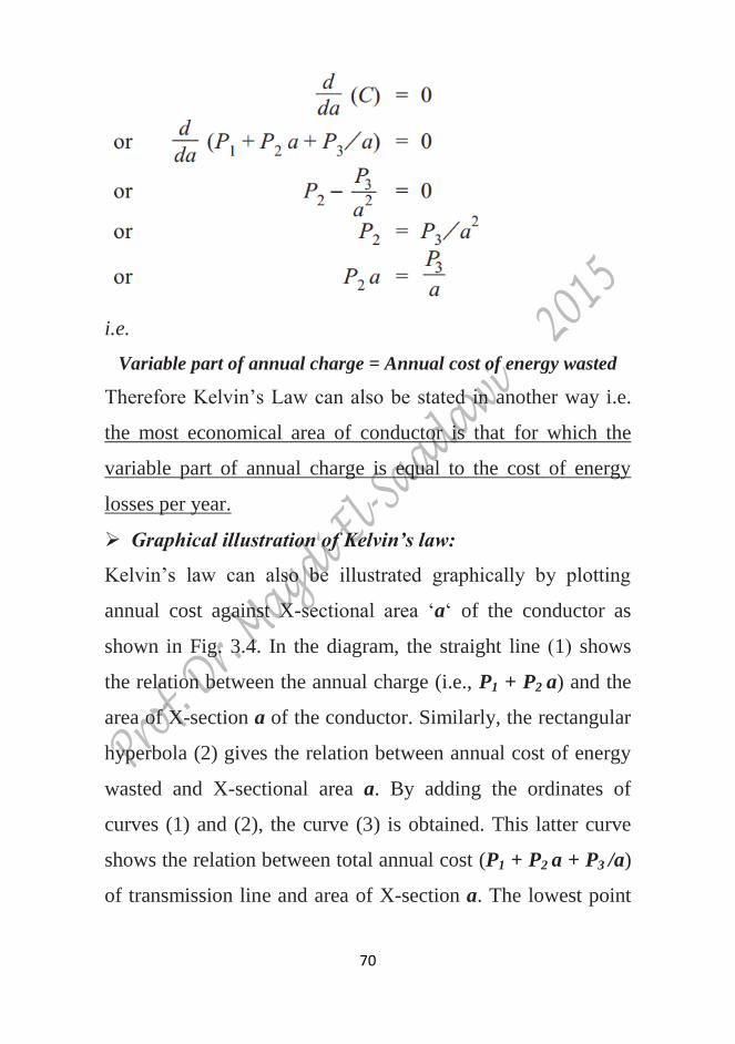
i.e.
Variable part of annual charge = Annual cost of energy wasted
Therefore Kelvin’s Law can also be stated in another way i.e.
the most economical area of conductor is that for which the
variable part of annual charge is equal to the cost of energy
losses per year.
Graphical illustration of Kelvin’s law:
Kelvin’s law can also be illustrated graphically by plotting
annual cost against X-sectional area ‘a’ of the conductor as
shown in Fig. 3.4. In the diagram, the straight line (1) shows
the relation between the annual charge (i.e., P1 + P2 a) and the
area of X-section a of the conductor. Similarly, the rectangular
hyperbola (2) gives the relation between annual cost of energy
wasted and X-sectional area a. By adding the ordinates of
curves (1) and (2), the curve (3) is obtained. This latter curve
shows the relation between total annual cost (P1 + P2 a + P3 /a)
of transmission line and area of X-section a. The lowest point

71
on the curve (i.e., point P) represents the most economical area
of X-section.
Fig. 3.4
Limitations of Kelvin’s law:
Although theoretically Kelvin’s law holds good, there is often
considerable difficulty in applying it to a proposed scheme of
power transmission. In practice, the limitations of this law are:
(i) It is not easy to estimate the energy loss in the line
without actual load curves, which are not available at the
time of estimation.
(ii) The assumption that annual cost on account of interest and
depreciation on the capital outlay is in the form P1 + P2 a
is strictly speaking not true. For instance, in cables neither
72
the cost of cable dielectric and sheath nor the cost of
laying vary in this manner.
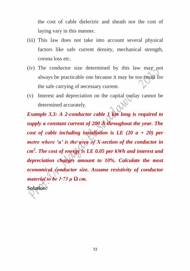
(iii) This law does not take into account several physical
factors like safe current density, mechanical strength,
corona loss etc.
(iv) The conductor size determined by this law may not
always be practicable one because it may be too small for
the safe carrying of necessary current.
(v) Interest and depreciation on the capital outlay cannot be
determined accurately.
Example 3.3: A 2-conductor cable 1 km long is required to
supply a constant current of 200 A throughout the year. The
cost of cable including installation is LE (20 a + 20) per
metre where ‘a’ is the area of X-section of the conductor in
cm2. The cost of energy is LE 0.05 per kWh and interest and
depreciation charges amount to 10%. Calculate the most
economical conductor size. Assume resistivity of conductor
material to be 1·73 µ Ω cm.
Solution:
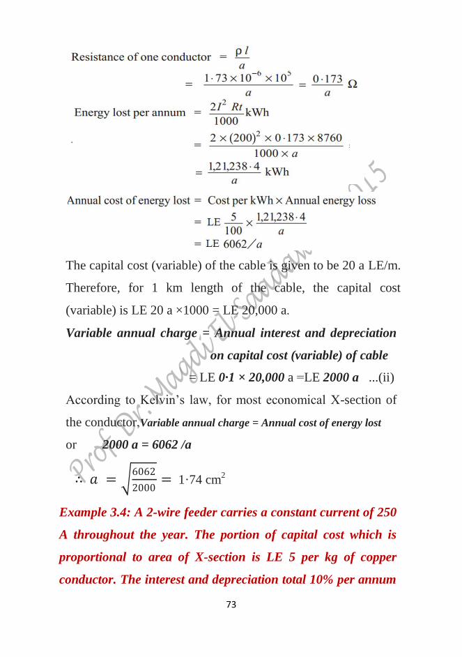
73
The capital cost (variable) of the cable is given to be 20 a LE/m.
Therefore, for 1 km length of the cable, the capital cost
(variable) is LE 20 a ×1000 = LE 20,000 a.
Variable annual charge = Annual interest and depreciation
on capital cost (variable) of cable
= LE 0·1 × 20,000 a =LE 2000 a ...(ii)
According to Kelvin’s law, for most economical X-section of
the conductor,Variable annual charge = Annual cost of energy lost
or 2000 a = 6062 /a
∴ 𝑎 = 6062
2000= 1·74 cm
2
Example 3.4: A 2-wire feeder carries a constant current of 250
A throughout the year. The portion of capital cost which is
proportional to area of X-section is LE 5 per kg of copper
conductor. The interest and depreciation total 10% per annum

74
and the cost of energy is 5 P per kWh. Find the most
economical area of X-section of the conductor. Given that the
density of copper is 8.93 gm/cm3 and its specific resistance is
1.73 × 10⁻⁸
Ω m.
Solution: Consider 1 metre length of the feeder. Let a be the most
economical area of X-section of each conductor in m2.
3.7.2 Economic choice of transmission voltage
It has been shown earlier in the chapter that if transmission
voltage is increased, the volume of conductor material required
is reduced. This decreases the expenditure on the conductor

75
material. It may appear advisable to use the highest possible
transmission voltage in order to reduce the expenditure on
conductors to a minimum. However, it may be remembered
that as the transmission voltage is increased, the cost of
insulating the conductors, cost of transformers, switchgear and
other terminal apparatus also increases. Therefore, for every
transmission line, there is optimum transmission voltage,
beyond which there is nothing to be gained in the matter of
economy. The transmission voltage for which the cost of
conductors, cost of insulators, transformers, switchgear and
other terminal apparatus is minimum: is called economical
transmission voltage.
The method of finding the economical transmission voltage is
as follows. Power to be transmitted, generation voltage and
length of transmission line are assumed to be known. We
choose some standard transmission voltage and work out the
following costs:
(i) Transformers: at the generating and receiving ends of
transmission line. For a given power, this cost increases
slowly with the increase in transmission voltage.
(ii) Switchgear: This cost also increases with the increase in
transmission voltage.
(iii) Lightning arrestor: This cost increases rapidly with the
increase in transmission voltage.
76
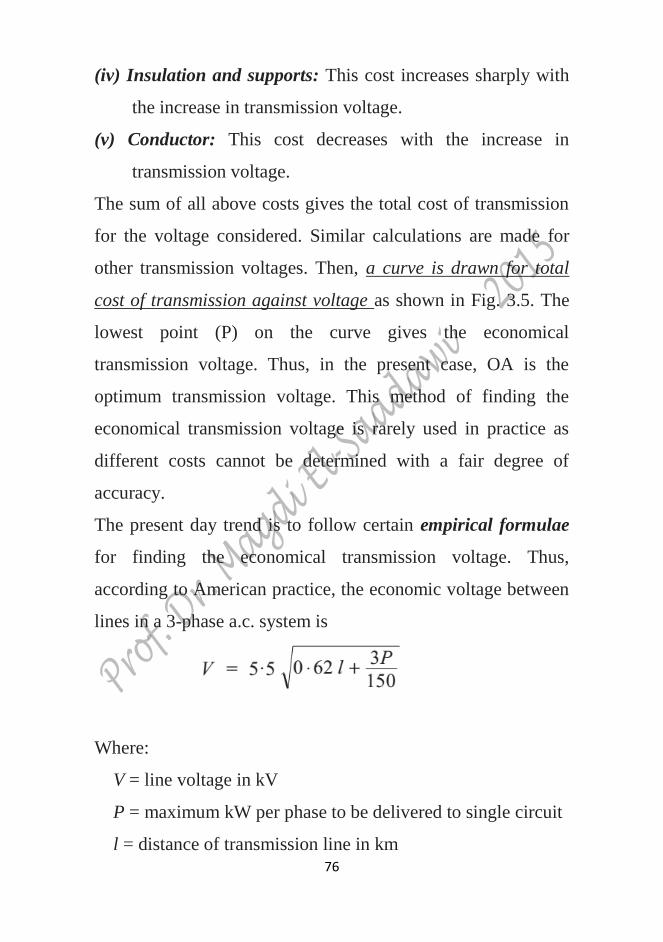
(iv) Insulation and supports: This cost increases sharply with
the increase in transmission voltage.
(v) Conductor: This cost decreases with the increase in
transmission voltage.
The sum of all above costs gives the total cost of transmission
for the voltage considered. Similar calculations are made for
other transmission voltages. Then, a curve is drawn for total
cost of transmission against voltage as shown in Fig. 3.5. The
lowest point (P) on the curve gives the economical
transmission voltage. Thus, in the present case, OA is the
optimum transmission voltage. This method of finding the
economical transmission voltage is rarely used in practice as
different costs cannot be determined with a fair degree of
accuracy.
The present day trend is to follow certain empirical formulae
for finding the economical transmission voltage. Thus,
according to American practice, the economic voltage between
lines in a 3-phase a.c. system is
Where:
V = line voltage in kV
P = maximum kW per phase to be delivered to single circuit
l = distance of transmission line in km

77
It may be noted here that in the above formula, power to be
transmitted and distance of transmission line have been taken
into account. It is because both these factors influence the
economic voltage of a transmission line. This can be easily
explained. If the distance of transmission line is increased, the
cost of terminal apparatus is decreased, resulting in higher
economic transmission voltage. Also if power to be transmitted
is large, large generating and transforming units can be
employed. This reduces the cost per kW of the terminal station
equipment.
Fig. 3.5
3.8 Requirements of Satisfactory Electric Supply

78
The electric power system in India is 3-phase a.c. operating at a
frequency of 50 Hz. The power station delivers power to
consumers through its transmission and distribution systems.
The power delivered must be characterized by constant or
nearly constant voltage, dependability of service, balanced
voltage, and efficiency so as to give minimum annual cost,
sinusoidal waveform and freedom from inductive interference
with telephone lines.
(i) Voltage regulation.
A voltage variation has a large effect upon the operation of
both power machinery and lights. A motor is designed to have
its best characteristics at the rated voltage and consequently a
voltage that is too high or too low will result in a decrease in
efficiency. If the fluctuations in the voltage are sudden, these
may cause the tripping of circuit breakers and consequent
interruptions to service. Usually the voltage at the generator
terminals, where this is done, in some cases the voltage
variations at the load may be made sufficiently small by
keeping the resistance and reactance of the lines and feeders
low.
(ii) Dependability.
One important requirement of electric supply is to furnish
uninterrupted service. The losses which an industrial consumer
sustains due to the failure of electric power supply are usually
vastly greater than the actual value of the power that he would

79
use during this period. It is on account of the expense of idle
workmen and machines and other overhead charges.
Interruptions to service cause irritation and are sometimes
positively dangerous to life and property. For example, failure
of power in hospitals, in crowded theatres and stores may lead
to very grave consequences. Therefore, it is the duty of electric
supply company to keep the power system going and to furnish
uninterrupted service.
(iii) Balanced voltage.
It is very important that the poly-phase voltage should be
balanced. If an unbalanced poly-phase voltage is supplied to a
consumer operating synchronous or induction motors, it will
result in a decrease in the efficiency of his machinery and also
a decrease in its maximum power output. Motors called upon
to deliver full load when their terminal voltages are unbalanced
are liable to considerable damage due to overheating. One
method of maintaining balance of voltage is by having
balanced loads connected to the circuit.
(iv) Efficiency.
The efficiency of a transmission system is not of much
importance in itself. The important economic feature of the
design being the layout of the system as a whole so as to
perform the requisite function of generating and delivering
power with a minimum overall annual cost. The annual cost
can be minimized to a considerable extent by taking care of
80
power factor of the system. It is because losses in the lines and
machinery are largely determined by power factor. Therefore,
it is important that consumers having loads of low power factor
should be penalized by being charged at a higher rate per kWh
than those who take power at high power factors. Loads of low
power factor also require greater generator capacity than those
of high power factor (for the same amount of power) and
produce larger voltage drops in the lines and transformers.
(v) Frequency.
The frequency of the supply system must be maintained
constant. It is because a change in frequency would change the
motor speed, thus interfering with the manufacturing
operations.
(vi) Sinusoidal waveform.
The alternating voltage supplied to the consumers should have
a sine waveform. It is because any harmonics which might be
present would have detrimental effect upon the efficiency and
maximum power output of the connected machinery.
Harmonics may be avoided by using generators of good design
and by avoidance of high flux densities in transformers.
(vii) Freedom from inductive interference.
Power lines running parallel to telephone lines produce
electrostatic and electromagnetic field disturbances. These
fields tend to cause objectionable noises and hums in the
apparatus connected to communication circuits. Inductive
81
interference with telephone lines may be avoided by limiting as
much as possible the amount of zero-sequence and harmonic
current and by the proper transposition of both power lines and
telephone lines.

82
Exercise 3
1. What is the percentage saving in copper feeder if the line
voltage in a 2-wire d.c. system is raised from 220 V to 500 V
for the same power transmitted over the same distance and
having the same power loss? Ans. 80·64%
2. A single phase a.c. system supplies a load of 200 kW and if
this system is converted to 3-phase, 3-wire a.c. system by
running a third similar conductor, calculate the 3-phase load
that can now be supplied if the voltage between the
conductors is the same. Assume the power factor and
transmission efficiency to be the same in the two cases
Ans. 400 kW
3. A 50 km long transmission line supplies a load of 5 MVA at
0·8 p.f. lagging at 33 kV. The efficiency of transmission is
90%. Calculate the volume of aluminium conductor required
for the line when (i) single phase, 2-wire system is used (ii)
3-phase, 3-wire system is used. The specific resistance of
aluminium is 2·85 × 10−8
Ωm. Ans. 16.35 m3, 12.27 m
3
4. A sub-station supplies power at 11 kV, 0·8 p.f. lagging to a
consumer through a single phase transmission line having
total resistance (both go and return) of 0.15 Ω. The voltage
drop in the line is 15%. If the same power is to be supplied
to the same consumer by two wire d.c. system by a new line

83
having a total resistance of 0·05 Ω and if the allowable
voltage drop is 25%, calculate the d.c. supply voltage.
Ans. 4400 V
5. The cost of a 3-phase overhead transmission line is LE
(25000 a + 2500) per km where ‘a’ is the area of X-section
of each conductor in cm2. The line is supplying a load of 5
MW at 33 kV and 0·8 p.f. lagging assumed to be constant
throughout the year. Energy costs 4 P per kWh and interest
and depreciation total 10% per annum. Find the most
economical size of the conductor. Given that specific
resistance of conductor material is 10−6
Ω cm.
Ans. 0.71 cm2
6. Determine the most economical cross-section for a 3-phase
transmission line, 1 km long to supply at a constant voltage
of 110 kV for the following daily load cycle:
6 hours 20 MW at p.f. 0·8 lagging
12 hours 5 MW at p.f. 0·8 lagging
6 hours 6 MW at p.f. 0·8 lagging
The line is used for 365 days yearly. The cost per km of line
including erection is LE (9000+ 6000 a) where ‘a’ is the area
of X-section of conductor in cm2. The annual rate of interest
and depreciation is 10% and the energy costs 6 P per kWh.
The resistance per km of each conductor is 0·176 /a.
Ans. 1·56 cm2