Embed Size (px)
Citation preview

COMMON RAIL INJECTORS TESTER
STARDEX® 0602

Safety rules for working with STARDEX 0602.
Before using the device STARDEX 0602 (further “the test bench”) read this manual
carefully.
The test bench should be plugged only in a three-phase circuit of alternative current 380W
with grounding. In order to power up the test bench use only a supply cable from the
delivery kit.
Getting of electrical charges on the body of the test bench is strongly prohibited!
Getting of liquid inside the test bench is strongly prohibited!
Test bench body is constructed to protect its components from mechanical impact while
operating. Avoid body damage, do not drop the test bench and do not put any heavy
objects on its cover.
At any sign of defect as smoke, sparking or specific smell, unplug the test bench
immediately and contact the nearest STARDEX service center.
All cables connected to the test bench must be supplied with standard plugs without
mechanical damage.
Opening operating test bench is strictly prohibited.
Store and use away from children and pets.
The test bench is designed to work with Common Rail system. A user must understand the
structure and principle of operation of high pressure injection systems.
Incorrect use of the test bench may lead to breakage of the equipment or user’s injury.

Specifications and operation directions
European version of the test bench
Dimensions 1000х620х1530mm
AC power supply Three-phase 400V
Power consumption in stand-by mode 90W
Power consumption in maximum load mode 4KW
Operating temperature from +100С to + 300С
Relative air humidity No more than 90% at 250С
Purpose and range of application.
STARDEX 0602 is a highly professional universal test bench for testing injectors of
Common Rail system of different manufacturers, brands and models.
STARDEX 0602 is reliable and easy to work with. The process of injector testing is
completely automatic and does not require any specific knowledge and skills from an
operator. STARDEX 0602 contains more than 1150 automatic testplans for testing
Bosch, Delphi, Denso, Siemens (Сontinental), Caterpillar injectors. The test bench is
equipped with a measuring unit which measures delivery and return flow quickly and
accurately and automatically puts results into the summary table. It is enough to
install injectors onto STARDEX 0602, select their type and serial number and start
test by pressing only one button, at the end the test bench creates a detail report of
injectors’ test.
The test bench is specified to test from one to four injectors simultaneously.
It works both with electromagnetic and piezoelectric Common Rail injectors.
The test bench is able to produce pressure up to 1700 bar. A protective shroud made
of transparent plexiglas closes the working area, ensures good protection of a user
from every possible accident on high-pressure lines.
There is a mode of hand control for advanced users when an operator can choose
pump revolution speed, width and frequency of injection pulse, pressure in the fuel
rail, measuring units. There is a possibility to create and save own testplans.

STARDEX 0602 enables to conduct a test of current characteristics of an injector,
with the precise diagram which is displayed on the screen.
STARDEX 0602 also enables to get a repair code for Delphi injectors.
The test bench is controlled by a keyboard and a mouse or by navigating buttons on
the front panel. All necessary information is displayed on the colour LCD screen (6.5
in). It is possible to connect the test bench to a detachable screen (included in the
supply kit).
Installing and connecting.
Remove package from the test bench and set it on its wheels.
Distance between the wall and the back panel must be not less than 0,3 m for free
work of the cooling fan.
The front and back panels must be opened with the help of special key from the
supply kit in order to make sure there are no damages of the equipment, wiring and
fuel lines which may be caused by incorrect transporting.

Pour a calibration fluid into the mouth of the tank and open its ventilation by turning
a special valve on the cover of the tank.
Switch on the power module by its button situated on the back panel of STARDEX
0303.

Connect a wireless module for the mouse and the keyboard to a free USB port.
(By option) Connect the detachable screen from the supply kit.
Fix back and front panels on the test bench again.
Plug into a three-phase circuit of alternative current 380W with grounding with the
power cable.

Fix the automatic power valve situated on the left panel of the test bench in ON-
position.
Run the loading of the operation system by the ON button on the front panel of
STARDEX 0303.
The test bench is ready to be used after the operation system is loaded.
The test bench is switched off by the OFF button on the front panel of STARDEX
0303. When the light diode on the front panel of STARDEX 0303 is red, switch the
lever of the automatic power on the left panel of the test bench in OFF-position.
Description of connectors and navigation buttons.
1
2
3
4
5
6 7 8 9
10 11 12 13 14
15
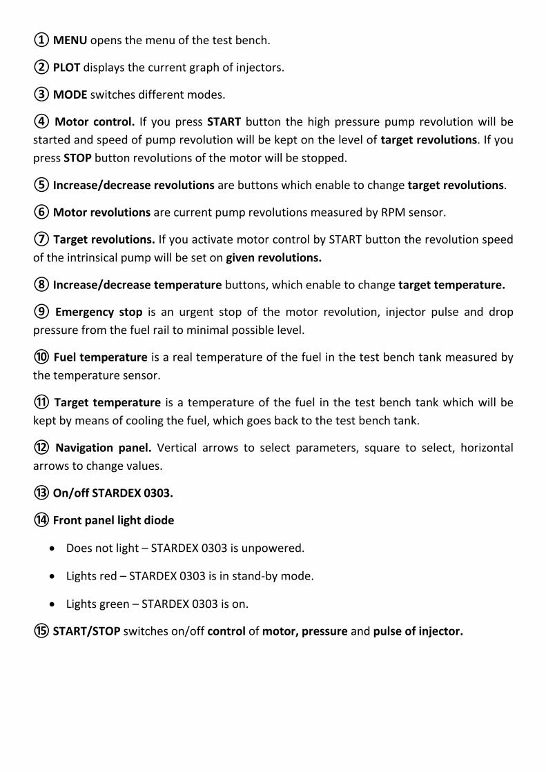
① MENU opens the menu of the test bench.
② PLOT displays the current graph of injectors.
③ MODE switches different modes.
④ Motor control. If you press START button the high pressure pump revolution will be
started and speed of pump revolution will be kept on the level of target revolutions. If you
press STOP button revolutions of the motor will be stopped.
⑤ Increase/decrease revolutions are buttons which enable to change target revolutions.
⑥ Motor revolutions are current pump revolutions measured by RPM sensor.
⑦ Target revolutions. If you activate motor control by START button the revolution speed
of the intrinsical pump will be set on given revolutions.
⑧ Increase/decrease temperature buttons, which enable to change target temperature.
⑨ Emergency stop is an urgent stop of the motor revolution, injector pulse and drop
pressure from the fuel rail to minimal possible level.
⑩ Fuel temperature is a real temperature of the fuel in the test bench tank measured by
the temperature sensor.
⑪ Target temperature is a temperature of the fuel in the test bench tank which will be
kept by means of cooling the fuel, which goes back to the test bench tank.
⑫ Navigation panel. Vertical arrows to select parameters, square to select, horizontal
arrows to change values.
⑬ On/off STARDEX 0303.
⑭ Front panel light diode
Does not light – STARDEX 0303 is unpowered.
Lights red – STARDEX 0303 is in stand-by mode.
Lights green – STARDEX 0303 is on.
⑮ START/STOP switches on/off control of motor, pressure and pulse of injector.

① Fuel rail plug.
② High pressure pump outlet.
③ Injector delivery measuring lines.
④ Injector back flow measuring lines.
⑤ Pressure regulator.
⑥ Back flow of fuel rail.
1
2
3
4
5
1
6
7
8
9
10
⑦ Pressure sensor connector.
⑧ Pressure regulator connector.
⑨ Injector connector.
⑩ Pressure sensor.
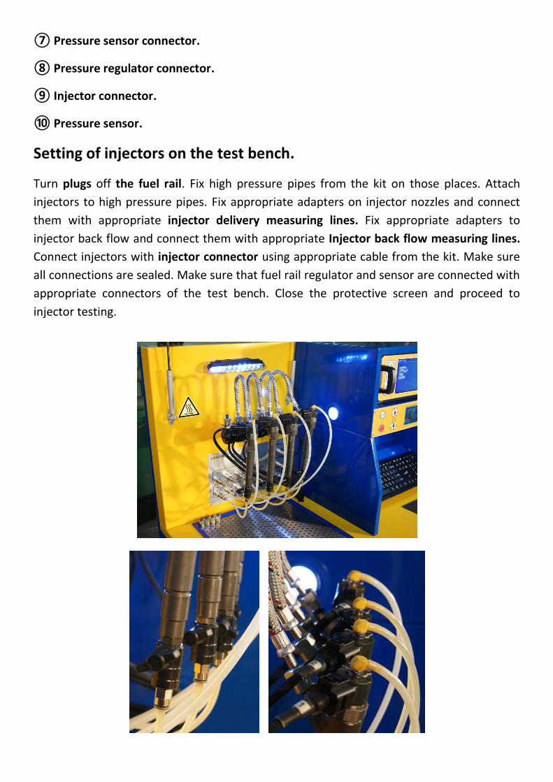
Setting of injectors on the test bench.
Turn plugs off the fuel rail. Fix high pressure pipes from the kit on those places. Attach
injectors to high pressure pipes. Fix appropriate adapters on injector nozzles and connect
them with appropriate injector delivery measuring lines. Fix appropriate adapters to
injector back flow and connect them with appropriate Injector back flow measuring lines.
Connect injectors with injector connector using appropriate cable from the kit. Make sure
all connections are sealed. Make sure that fuel rail regulator and sensor are connected with
appropriate connectors of the test bench. Close the protective screen and proceed to
injector testing.

Main display (INJECTORS).
① MANUAL is a manual mode for testing injectors.
② TESTPLAN is a semi-automatic mode for testing injectors according to testplan.
③ AUTO is an automatic test mode.
④ CODING - getting an injector repair code.
Testing of injectors in TESTPLAN mode.
After going to TESTPLAN the screen for selecting the type of Common Rail injectors will
open.
1
2
3
4
1
2
3
4
5
6
7

① BOSCH – electromagnetic injectors Bosch.
② DELPHI – electromagnetic injectors Delphi.
③ DENSO – electromagnetic injectors Denso.
④ SIEMENS – piezoelectric injectors Siemens.
⑤ PIEZO BOSCH – piezoelectric injectors Bosch.
⑥ CATERPILLAR – electromagnetic injectors Caterpillar.
⑦ Quit to INJECTORS screen.
All Common Rail injectors have different current-voltage characteristics so it is extremely
important to select the type of the tested injector correctly. Incorrect choice may cause
injector or device damage!
After choosing the type of the injector, the screen for selecting serial number will open.
① Filter is a line for inputting a part of a serial number to simplify search in the data base.
Data base records which do not contain the inserted part of the number will be
automatically removed from the screen.
② Quit to INJECTORS screen.
1 2

After selecting injector serial number the screen for testing injectors in TESTPLAN mode will
open.
① Headline is a line where manufacturer and serial number of tested injectors are shown.
② Test step shows the name of the current testing mode, horizontal arrows change
modes.
③ Target revolutions. If you activate motor control using ON/OFF switch in the section
MOTOR or by START/STOP button, the speed of the test bench high pressure pump
revolution will be established on the level of target revolutions.
④ Target pressure. If you activate fuel rail pressure control by ON/OFF switch in the
section PRESSURE or by START/STOP button, real pressure in the fuel rail will be
established on the level of target pressure.
⑤ Pulse width is the exact period of time when the injector is operating, which is called
pulse width of injection or duration of injection, it is measured in microseconds.
⑥ Pulse frequency is the number of complete injections per 1 sec measured in Hz.
⑦ Delivery/back flow data is reference values for results of injector delivery/back flow for
the current test step.
⑧ Result field serves for inserting the value of delivery or back flow of injectors into
report. Numeral on the left of the field corresponds to the number of the injector tested.
1
2
3
4
5
6
7
8
9
10
11
12
13
14
15
16 17
18
19
o

Quantity of fields for inserting displayed on the screen depends on quantity of tested
injectors.
⑨ Information area is an opening section where the mode of the current test step is
described.
⑩ Motor revolutions are real revolutions of the high pressure pump measured by RPM
sensor.
⑪ Real pressure is indication of the pressure sensor in the fuel rail.
⑫ Select buttons are used for choosing the number of injectors tested. Each numeral
corresponds to numerated wire connected to injector.
Selection buttons have 3 states:
Lights red – injector is selected
Winks red – injector is pulsed
Does not light – injector is not selected
⑬ Units of measurement switchable indicator which changes measuring units of
delivery/back flow data as well as units of the result field.
ml/200str – milliliter per 200 cycles.
ml/min – milliliter per minute.
⑭ AUTO is used for automatically inserting measurements taken from the flow meters to
the result field.
⑮ START/STOP switches on/off control of motor, pressure and injector pulse.
⑯ Motor control is ON/OFF switch in the section MOTOR. If the switch is ON, test bench
high pressure pump revolution will be launched and pump revolution will be kept on the
level of target revolutions. If the switch is OFF, revolution of the pump will be stopped.
⑰ Pressure control is ON/OFF switch in the section PRESSURE. If the switch is ON, control
of the reduction valve in the fuel rail will start so that real pressure in the rail will be kept
on the level of target pressure. If the switch is OFF, control of the reduction valve in the rail
will be over and pressure will fall to minimal.
⑱ Injector pulse control is ON/OFF switch in the section INJECTORS. If the switch is ON,
the pulse on selected injectors with given width and frequency will be launched. If the
switch is OFF, the pulse of injectors will be stopped.

⑲ Quit to Main screen.
Install injectors onto the test bench. Select type and serial number of tested injectors.
Select tested injectors by select buttons. Press START/STOP and wait till pump revolutions
and fuel rail pressure are set on the given level. Wait about a minute so that injectors fill
line of the flow meter and make it free from air. Measure quantity of delivery and back flow
using flow meter menu in the right part of the display or by button AUTO. Proceed to the
next test step and continue this succession of actions. After the results of delivery and back
flow are inserted into the last test, press START/STOP in order to stop the test bench. Go to
the result screen.
Injector testing in MANUAL mode.
After going to MANUAL mode and selecting injector type and serial number, the screen for
testing in MANUAL mode will open.
Injector testing in MANUAL mode is similar to TESTPLAN mode with the exception that all
parameters must be set by a user.

Injector testing in AUTO mode.
After selecting AUTO mode, the screen for selecting injector type will open.
① BOSCH – electromagnetic injectors Bosch.
② DELPHI – electromagnetic injectors Delphi.
③ DENSO – electromagnetic injectors Denso.
④ SIEMENS – piezoelectric injectors Siemens.
⑤ PIEZO BOSCH – piezoelectric injectors Bosch.
⑥ CATERPILLAR – electromagnetic injectors Caterpillar.
⑦ Quit to INJECTORS screen.
All Common Rail injectors have different current-voltage characteristics so it is extremely
important to select the type of the tested injector correctly. Incorrect choice may cause
injector or device damage!
1
2
3
4
5
6
7

1 2
1
2
3
4
After choosing the injector type the screen for selecting injector serial number will open.
① Filter is a line for inputting a part of a serial number to simplify search in the data base.
Data base records which do not contain the inserted part of the number will be
automatically removed from the screen.
② Quit to INJECTORS screen.
After selecting injector serial number the screen for testing in AUTO mode will open.
① Headline is a line where type and number of tested injectors are displayed.

1 2
2
② Select buttons are used for choosing the number of injectors tested. Each numeral
corresponds to numerated wire connected to injector.
Lights red – injector is selected
Winks red – injector is pulsed
Does not light – injector is not selected
③ START/STOP is a button which switches on/off the automatic test.
④ Progress indicator shows the progress of the automatic test, when the indicator is filled
to the end the test bench stops its work and the result screen is opened on the display.
Install injectors onto the test bench. Select AUTO mode. Select type and serial number of
tested injectors. Mark tested injectors by select buttons. Press START/STOP and wait till
the automatic test is over. After that the result screen will be opened automatically.
Getting of repair codes for Delphi injectors. CODING mode.
After selecting CODING the display for selecting type of injectors will open (for now only
coding of 16-digit Delphi injectors is available).
After selecting type of injectors, the screen for selecting serial number will open.
① Filter is a line for inputting a part of a serial number to simplify search in the data base.
Data base records which do not contain the inserted part of the number will be
automatically removed from the screen.
② Quit to INJECTORS screen.

1
2
3
4
After selecting serial number the display of CODING test will open.
① Headline is a line where type and number of tested injectors are displayed.
② Select buttons are used for choosing the number of injectors tested. Each numeral
corresponds to numerated wire connected to injector.
Lights red – injector is selected
Winks red – injector is pulsed
Does not light – injector is not selected
③ START/STOP is a button which switches on/off CODING test.
④ Progress indicator shows the progress of the CODING test when the indicator is filled to
the end, the test bench stops its work and the result screen is opened on the display.
Install injectors onto the test bench. Select type and serial number of tested injectors. Mark
tested injectors by select buttons. Press START/STOP and wait till the CODING test is over.
After that the result screen will be opened automatically.

1
1
2
3
4
5
① Repair codes are new codes for tested injectors received as a result of the CODING test.
Additional menu.
If you move the mouse pointer to the right part of the display the additional menu will
appear.
① Current graph.
② Flow meter.
③ Test bench systems

1
2
1
3
4
④ Settings.
⑤ Result screen.
Current graph.
① Return – go back to the previous screen.
② Current scale – intensity of current in the injector circuit measured in Ampere.
③ Time scale – time measured in microseconds.
④ Select buttons – activate/deactivate display of the current graph for selected injector.
Color of graphs corresponds to color of buttons; numbers of buttons correspond to
numerated wire of injectors.

1
2
3
4
5
7 8 9 6 10 11
12
Flow meter.
① Result store is a button which, when pressed, saves current values of delivery and back
flow of injectors into the result screen.
② Measuring tube is a graphical image of delivery and back flow on the display. Four
tubes from the left part of the display show injector delivery, four tubes on the right show
back flow. Figures below each tube show value of injector delivery and back flow. Marks
min/max on tubes are graphical displays of delivery/back flow data. Numbers of tubes
coincide with numerated lines for measuring injector delivery and back flow.
③ Quit to the previous screen.
④ Delivery/back flow data is reference values for results of injector delivery and back
flow for the current test step.
⑤ Delivery measuring units is a switchable indicator which changes measuring units of
delivery/back flow data as well as units of the result field.
ml/200str – milliliter per 200 cycles.
ml/min – milliliter per minute.
⑥ Real revolutions.
⑦ Real pressure.

1
2
⑧ Pulse length.
⑨ Pulse frequency.
⑩ Injector pulse indicator shows the state of the injector pulse
winks – pulse is delivered to injectors
does not wink – pulse is off
⑪ Back flow measuring units is a switchable indicator which, when pressed, changes
measuring units for back flow. Back flow measuring units can be also changed in
delivery/back flow data and result field.
ml/200str – milliliter per 200 cycles.
ml/min – milliliter per minute.
⑫ Reset is a button which, when pressed, starts measuring of delivery and back flow value
for the given step of the test again.
Result screen
① Table column, which contains names of test steps and delivery/back flow data for
injector delivery and back flow.
② Table columns, which contain measurement results of delivery and back flow for every
tested injector.

1
2
3
4
5
6
Settings
① Display resolution sets resolution of an external monitor.
② Pressure sensor type is set according to the type of the pressure sensor connected to
the test bench.
1500 bar
1800 bar
③ Injector delivery measuring units sets used in tests by default measuring units of
injector delivery.
ml/min – milliliters per minute.
ml/200str – milliliters per 200 cycles.
④ Injector recovery measuring units sets used in tests by default measuring units of
injector back flow.
ml/min – milliliters per minute.
ml/200str – milliliters per 200 cycles.
⑤ Return – return to the previous screen.
⑥ Quit – quit to operation system Ubuntu Linux.

Supply kit.
Basic
STARDEX 0602 1 piece
Cable for connecting four Bosch injectors 1 piece
Cable for connecting four Delphi injectors 1 piece
Cable for connecting four Denso injectors 1 piece
Cable for connecting four Siemens/Bosch 1 piece
Multisystem cable for connecting four injectors 1 1 piece
Multisystem cable for connecting four injectors 2 1 piece
High pressure tube 14х1.5 12х1.5 4 pieces
High pressure tube 14х1.5 14х1.5 4 pieces
Plastic back flow connector for Bosch injectors 4 pieces
Plastic back flow connector pipe for Delphi injectors 4 pieces
Plastic tube d6мм 8 m
Quick-split connectors 8 pieces
Wireless mouse 1 piece
Wireless keyboard 1 piece
LCD display 1 piece
Technical description 1 piece


Warranty and technical support.
The equipment has 1 year warranty. The manufacturer is not responsible for the damage
due to violation of the operation terms, misuse including unskillful or mistaken personnel
actions and if there are traces of mechanical impact. Post-warranty service of device is
performed at cost components and the work. The manufacturer reserves the right to design
modifications, equipment and the warranty period without advance notice.
Shipping details.
Weight 250 kg.
Length 1000 mm.
Width 650 mm.
Height 1600 mm.
MANUFACTURED BY:
OY STARDEX LTD
PULTTITIE 2
00880 HELSINKI
FINLAND
+358 (0)44 5523130
www.stardex.fi