Embed Size (px)
Citation preview

© 2011 ANSYS, Inc. 1
Coil and PCB for Inductive Noise Solution for DC-DC Converter
2013.1.8
ANSYS Japan K.K.
Takahiro Koga

© 2011 ANSYS, Inc. 2
• Motivation and Summary
• Solutions
1. Electromagnetic Analysis 1. Coil : Magnetic Saturation (Maxwell)
2. PCB : Magnetic Coupling (Q3D Extractor)
3. Coil and PCB : Magnetic Coupling (Maxwell)
2. Circuit Simulation 1. Easy to Study with simple equivalent circuit (Simplorer)
2. Integrated System Simulation with FEA models (Simplorer)
• Conclusion
• Appendix: How about Harmonic Noise?
Agenda: Coil and PCB for Inductive Noise Solution
© 2011 ANSYS, Inc. 3
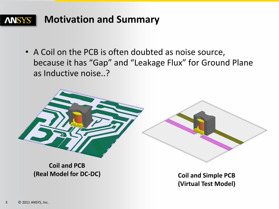
• A Coil on the PCB is often doubted as noise source, because it has “Gap” and “Leakage Flux” for Ground Plane as Inductive noise..?
Motivation and Summary
Coil and PCB (Real Model for DC-DC) Coil and Simple PCB
(Virtual Test Model)
© 2011 ANSYS, Inc. 4
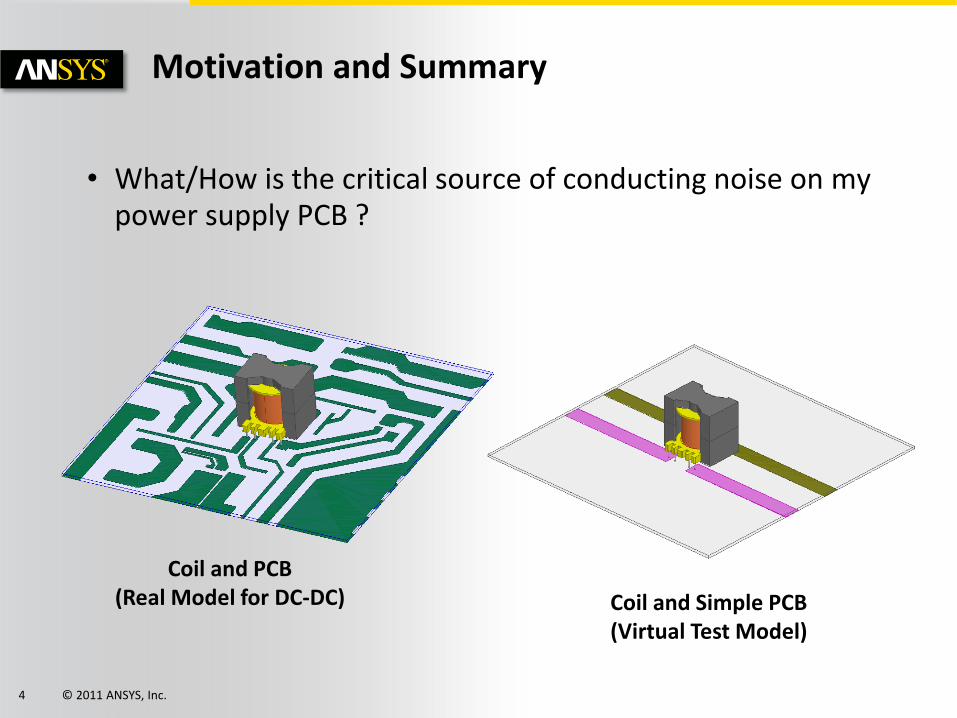
• What/How is the critical source of conducting noise on my power supply PCB ?
Motivation and Summary
Coil and PCB (Real Model for DC-DC) Coil and Simple PCB
(Virtual Test Model)
© 2011 ANSYS, Inc. 5
• Electromagnetics : Maxwell 3D
• Electromagnetics : Q3D Extractor
• Circuit : Simplorer
• Option (for Maxwell, Q3D Extractor)
ALinks for MCAD
Optimetrics
HPC Pack
Suite ANSYS Products

© 2011 ANSYS, Inc. 6
• Inductance vs. Input Current
• Magnetostatic
• Specification Max. Current:10A
• 1A ~ 10A
Sim. 1-1 Coil, Magnetic Nonliear Saturation (Maxwell)
Model
Excitation(Current) Setting
© 2011 ANSYS, Inc. 7
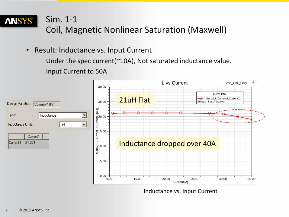
• Result: Inductance vs. Input Current
Under the spec current(~10A), Not saturated inductance value.
Input Current to 50A
Sim. 1-1 Coil, Magnetic Nonlinear Saturation (Maxwell)
0.00 10.00 20.00 30.00 40.00 50.00Current [A]
0.00
5.00
10.00
15.00
20.00
25.00
30.00
Ma
trix
1.L
(Cu
rre
nt1
,Cu
rre
nt1
) [u
H]
2nd_Coil_OnlyL vs Current
Curve Info
Matrix1.L(Current1,Current1)Setup1 : LastAdaptive
Inductance dropped over 40A
Inductance vs. Input Current
21uH Flat

© 2011 ANSYS, Inc. 8
• Result: Field Plot Mag_B on the Core
Not magnetic saturated -> Suitable core design
Sim. 1-1 Coil, Magnetic Nonlinear Saturation (Maxwell)
Max. 0.4[T]
5A
10A
Core’s BH Curve

© 2011 ANSYS, Inc. 9
• Additional Test: Field Plot Mag_B on the Core over 20A
Start to saturate( 0.4T~) over 20A , but still Inductance is sustained.
Sim. 1-1 Coil, Magnetic Nonlinear Saturation (Maxwell)
Max. 0.4[T]
20A 40A 50A
© 2011 ANSYS, Inc. 10
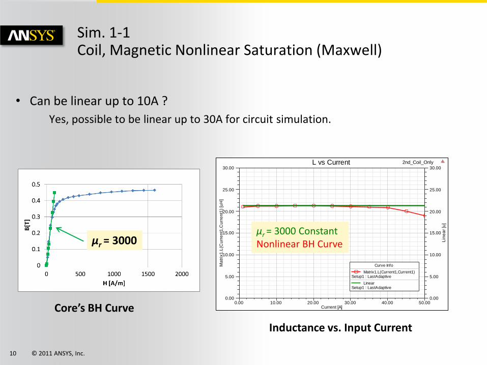
• Can be linear up to 10A ?
Yes, possible to be linear up to 30A for circuit simulation.
Sim. 1-1 Coil, Magnetic Nonlinear Saturation (Maxwell)
0.00 10.00 20.00 30.00 40.00 50.00Current [A]
0.00
5.00
10.00
15.00
20.00
25.00
30.00
Ma
trix
1.L
(Cu
rre
nt1
,Cu
rre
nt1
) [u
H]
0.00
5.00
10.00
15.00
20.00
25.00
30.00
Lin
ea
r [u
]
2nd_Coil_OnlyL vs Current
Curve Info
Matrix1.L(Current1,Current1)Setup1 : LastAdaptive
LinearSetup1 : LastAdaptive
μr = 3000 Constant Nonlinear BH Curve
Core’s BH Curve
μr = 3000
Inductance vs. Input Current
© 2011 ANSYS, Inc. 11
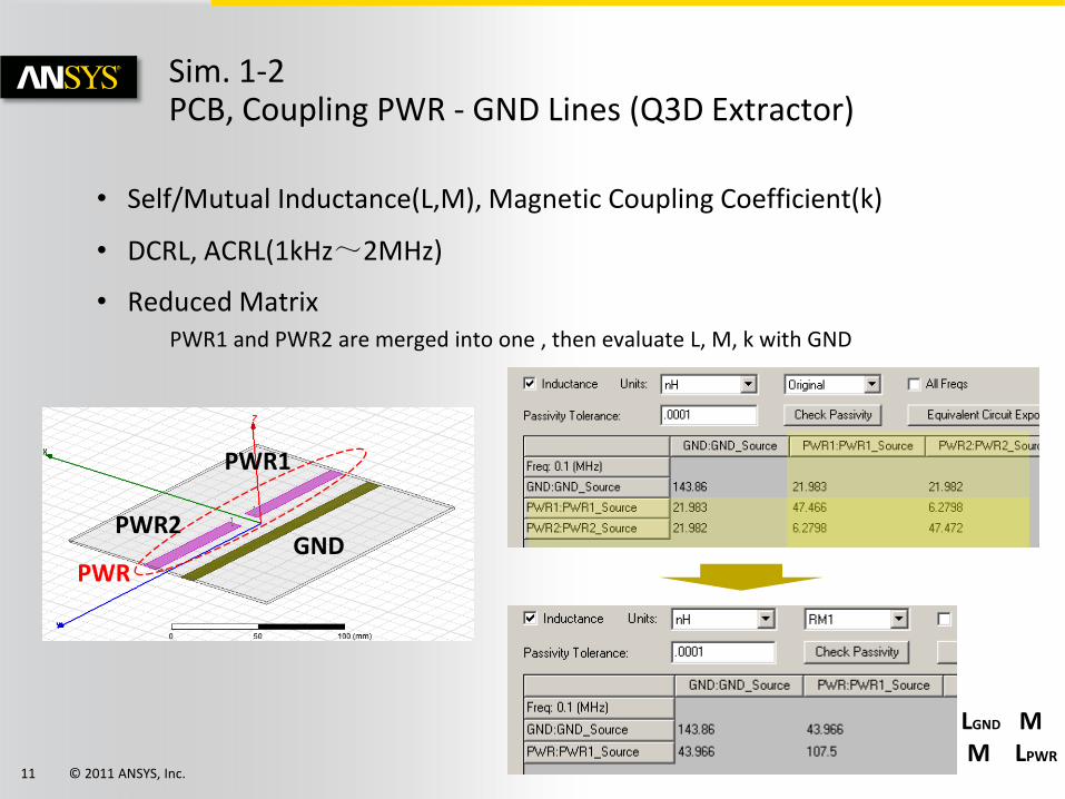
• Self/Mutual Inductance(L,M), Magnetic Coupling Coefficient(k)
• DCRL, ACRL(1kHz~2MHz)
• Reduced Matrix PWR1 and PWR2 are merged into one , then evaluate L, M, k with GND
Sim. 1-2 PCB, Coupling PWR - GND Lines (Q3D Extractor)
GND
PWR1
PWR2
PWR
LGND M M LPWR
© 2011 ANSYS, Inc. 12
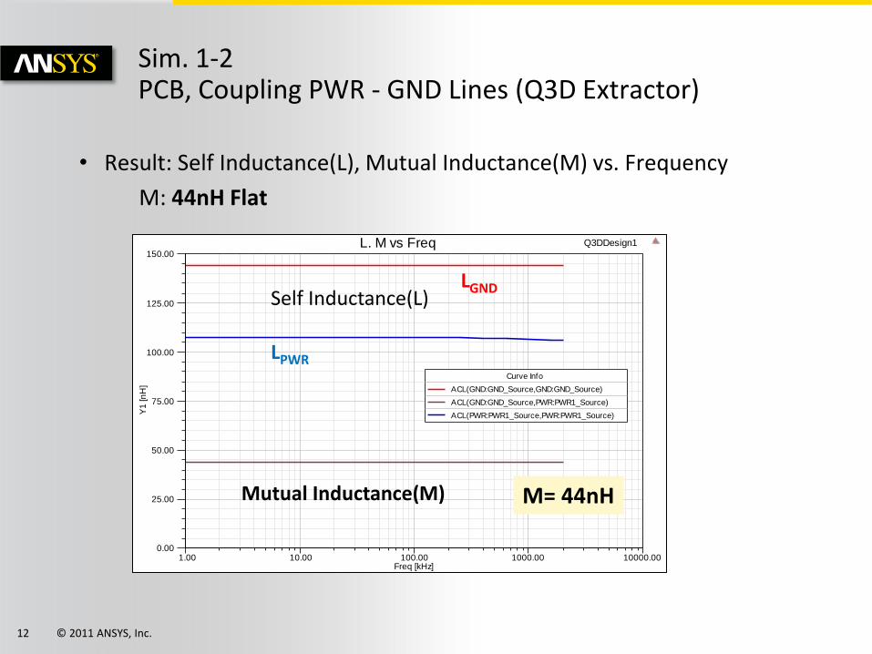
• Result: Self Inductance(L), Mutual Inductance(M) vs. Frequency
M: 44nH Flat
Sim. 1-2 PCB, Coupling PWR - GND Lines (Q3D Extractor)
1.00 10.00 100.00 1000.00 10000.00Freq [kHz]
0.00
25.00
50.00
75.00
100.00
125.00
150.00
Y1
[n
H]
Q3DDesign1L. M vs Freq
Curve Info
ACL(GND:GND_Source,GND:GND_Source)
ACL(GND:GND_Source,PWR:PWR1_Source)
ACL(PWR:PWR1_Source,PWR:PWR1_Source)
Mutual Inductance(M)
Self Inductance(L) LGND
LPWR
M= 44nH

© 2011 ANSYS, Inc. 13
• Result: Magnetic Coupling Coefficient(k) vs. Frequency
k: 0.35 Flat
Sim. 1-2 PCB, Coupling PWR - GND Lines (Q3D Extractor)
0.00 0.01 0.10 1.00 10.00Freq [MHz]
0.00
0.20
0.40
0.60
0.80
1.00
k
Q3DDesign1k vs Freq
Curve Info
kSetup1 : Sw eep1
k= 0.35
© 2011 ANSYS, Inc. 14
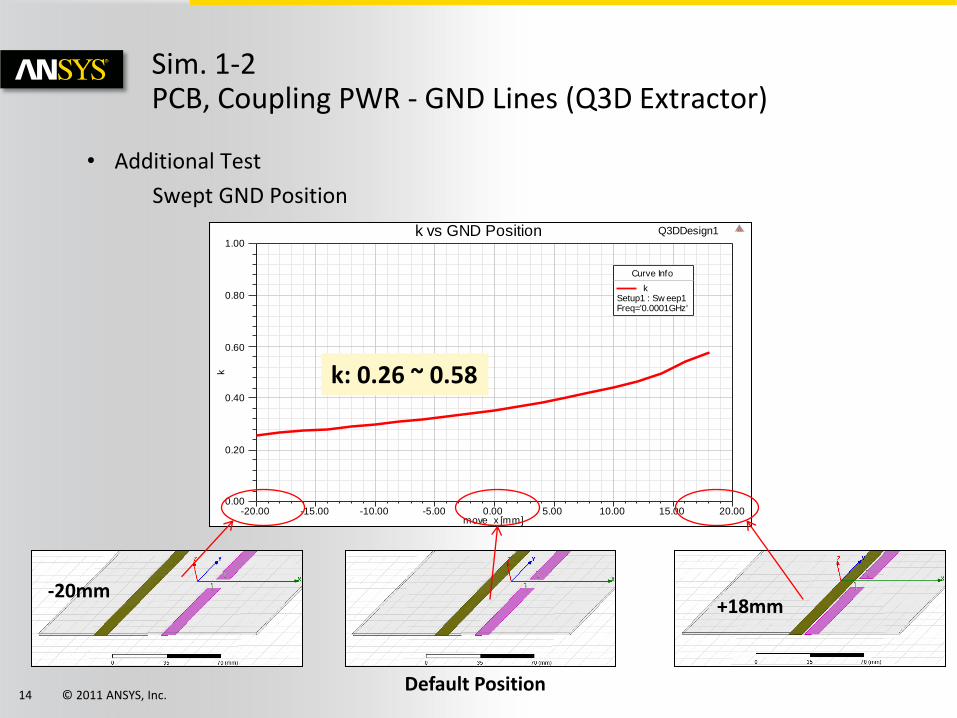
• Additional Test
Swept GND Position
Sim. 1-2 PCB, Coupling PWR - GND Lines (Q3D Extractor)
-20.00 -15.00 -10.00 -5.00 0.00 5.00 10.00 15.00 20.00move_x [mm]
0.00
0.20
0.40
0.60
0.80
1.00
kQ3DDesign1k vs GND Position
Curve Info
kSetup1 : Sw eep1Freq='0.0001GHz'
k: 0.26 ~ 0.58
Default Position
-20mm +18mm

© 2011 ANSYS, Inc. 15
• Self/Mutual Inductance(L,M), Magnetic Coupling Coefficient(k)
• Magnetostatics
• 1A~20A
Sim. 1-3 Coil and PCB, Coupling Coil - GND Lines (Maxwell)
Model
Top of view
GND
Coil
© 2011 ANSYS, Inc. 16
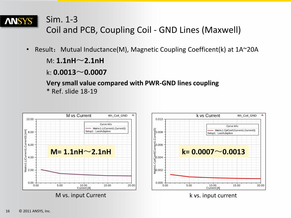
• Result:Mutual Inductance(M), Magnetic Coupling Coefficent(k) at 1A~20A
M: 1.1nH~2.1nH
k: 0.0013~0.0007
Very small value compared with PWR-GND lines coupling * Ref. slide 18-19
Sim. 1-3 Coil and PCB, Coupling Coil - GND Lines (Maxwell)
0.00 5.00 10.00 15.00 20.00Current [A]
0.00
2.00
4.00
6.00
8.00
10.00
Ma
trix
1.L
(Cu
rre
nt1
,Cu
rre
nt3
) [n
H]
4th_Coil_GNDM vs Current
Curve Info
Matrix1.L(Current1,Current3)Setup1 : LastAdaptive
M vs. input Current k vs. input current
M= 1.1nH~2.1nH
0.00 5.00 10.00 15.00 20.00Current [A]
0.000
0.002
0.004
0.006
0.008
0.010
Ma
trix
1.C
plC
oe
f(C
urr
en
t1,C
urr
en
t3)
4th_Coil_GNDk vs Current
Curve Info
Matrix1.CplCoef(Current1,Current3)Setup1 : LastAdaptive
k= 0.0007~0.0013

© 2011 ANSYS, Inc. 17
• Additional Test
Swept GND Position
Sim. 1-3 Coil and PCB, Coupling Coil - GND Lines (Maxwell)
-20.00 -15.00 -10.00 -5.00 0.00 5.00 10.00 15.00 20.00move_x [mm]
-0.0010
-0.0005
0.0000
0.0005
0.0010
Ma
trix
1.C
plC
oe
f(C
urr
en
t1,C
urr
en
t3)
5th_Coil_GND_Lineark vs GND Position
Curve Info
Matrix1.CplCoef(Current1,Current3)Setup1 : LastAdaptive
Default Position
-20mm +18mm
k= 0.00078~-0.00028
© 2011 ANSYS, Inc. 18
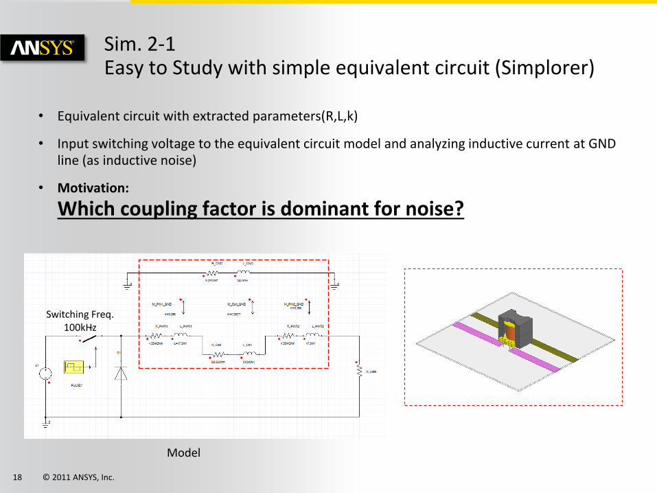
• Equivalent circuit with extracted parameters(R,L,k)
• Input switching voltage to the equivalent circuit model and analyzing inductive current at GND line (as inductive noise)
• Motivation:
Which coupling factor is dominant for noise?
Sim. 2-1 Easy to Study with simple equivalent circuit (Simplorer)
Model
Switching Freq. 100kHz

© 2011 ANSYS, Inc. 19
• Easy to Study Equivalent Circuit
Equivalent Circuit with extracted parameters
Sim. 2-1 Easy to Study with simple equivalent circuit (Simplorer)
Easy to Study Equivalent Circuit
GND
PWR1 PWR2
Coil
M: GND – PW1 M: GND – PWR2 M: GND - Coil
Coil
PWR2
PWR1
GND

© 2011 ANSYS, Inc. 20
• Result #1: Waveform Coil(Power line) Current and Induced Current at GND line
Max 0.84A in the GND Line @ Max. 10A in the Power Line
Sim. 2-1 Easy to Study with simple equivalent circuit (Simplorer)
Current at Coil, PWR line
Current at GND line (Inductive Noise)
100.00 150.00 200.00 250.00 300.00 350.00 400.00Time [us]
-2.00
0.00
2.00
4.00
6.00
8.00
10.00
Y1
[A
]
1st_AllCurrent
Curve Info max rms
R_GND.ITR
0.8394 0.5014
R_PWR1.ITR
9.8561 7.3096

© 2011 ANSYS, Inc. 21
• Result #2: What happens if GND is floated?
No current induced (No noise)
Sim. 2-1 Easy to Study with simple equivalent circuit (Simplorer)
100.00 150.00 200.00 250.00 300.00 350.00 400.00Time [us]
-2.00
0.00
2.00
4.00
6.00
8.00
10.00
Y1
[A
]
2nd_GND_FloatCurrent
Curve Info max rms
R_GND.ITR
0.0000 0.0000
R_PWR1.ITR
9.8545 7.3094
Connect High impedance (1Mohm) to GND
Current at Coil, PWR line
Current at GND line (Inductive Noise)
© 2011 ANSYS, Inc. 22
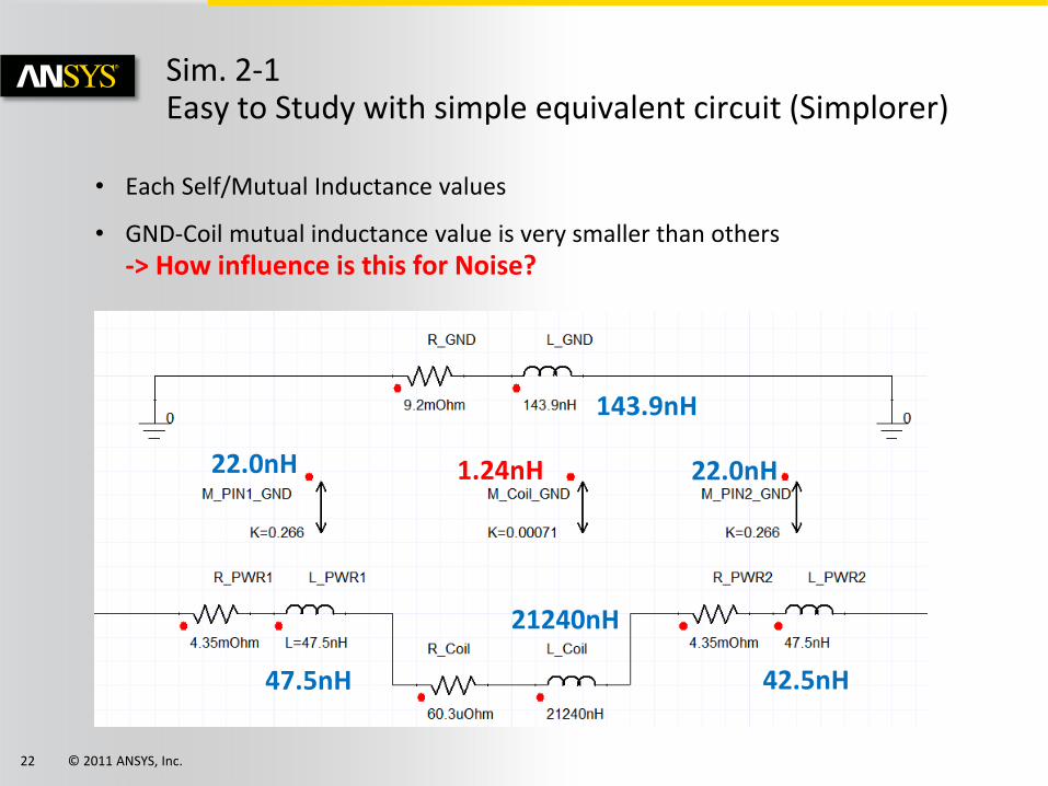
• Each Self/Mutual Inductance values
• GND-Coil mutual inductance value is very smaller than others -> How influence is this for Noise?
Sim. 2-1 Easy to Study with simple equivalent circuit (Simplorer)
47.5nH 42.5nH
143.9nH
21240nH
22.0nH 22.0nH 1.24nH
© 2011 ANSYS, Inc. 23
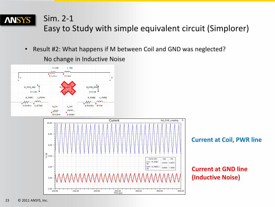
• Result #2: What happens if M between Coil and GND was neglected?
No change in Inductive Noise
Sim. 2-1 Easy to Study with simple equivalent circuit (Simplorer)
100.00 150.00 200.00 250.00 300.00 350.00 400.00Time [us]
-2.00
0.00
2.00
4.00
6.00
8.00
10.00
Y1
[A
]
3rd_EVB_couplingCurrent
Curve Info max rms
R_GND.ITR
0.8163 0.4876
R_PWR1.ITR
9.8560 7.3096
Current at Coil, PWR line
Current at GND line (Inductive Noise)
© 2011 ANSYS, Inc. 24
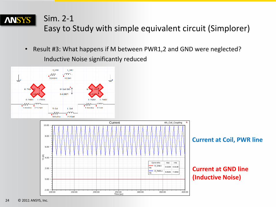
• Result #3: What happens if M between PWR1,2 and GND were neglected?
Inductive Noise significantly reduced
Sim. 2-1 Easy to Study with simple equivalent circuit (Simplorer)
100.00 150.00 200.00 250.00 300.00 350.00 400.00Time [us]
-2.00
0.00
2.00
4.00
6.00
8.00
10.00
Y1
[A
]
4th_Coil_CouplingCurrent
Curve Info max rms
R_GND.ITR
0.0230 0.0138
R_PWR1.ITR
9.8545 7.3094
Current at Coil, PWR line
Current at GND line (Inductive Noise)
© 2011 ANSYS, Inc. 25
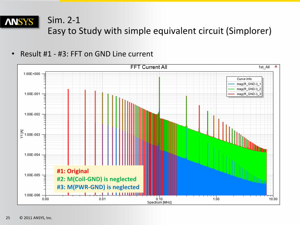
• Result #1 - #3: FFT on GND Line current
Sim. 2-1 Easy to Study with simple equivalent circuit (Simplorer)
#1: Original #2: M(Coil-GND) is neglected #3: M(PWR-GND) is neglected

© 2011 ANSYS, Inc. 26
• Maxwell and Q3D models brought into Simplorer
• Previous analysis confirmed the coupling between the Coil and GND Line can be neglected
Sim. 2-2 Integrated System Simulation with FEA models (Simplorer)
Integrated model
Q3D Extractor
Maxwell
© 2011 ANSYS, Inc. 27
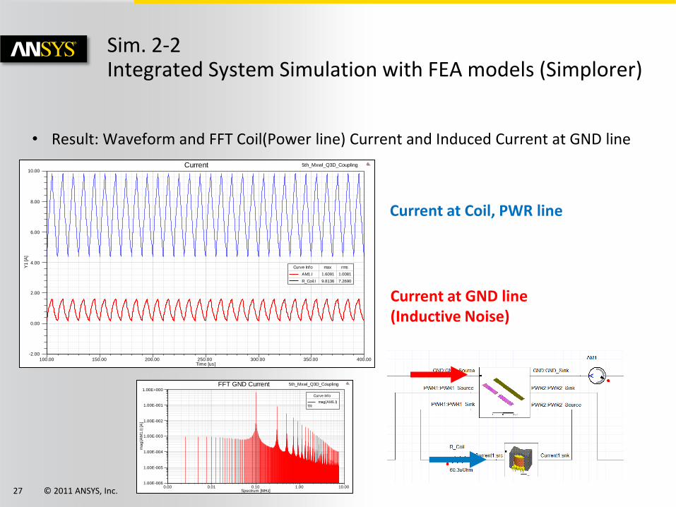
• Result: Waveform and FFT Coil(Power line) Current and Induced Current at GND line
Sim. 2-2 Integrated System Simulation with FEA models (Simplorer)
100.00 150.00 200.00 250.00 300.00 350.00 400.00Time [us]
-2.00
0.00
2.00
4.00
6.00
8.00
10.00
Y1
[A
]
5th_Mxwl_Q3D_CouplingCurrent
Curve Info max rms
AM1.I 1.6091 1.0081
R_Coil.I 9.8136 7.2690
0.00 0.01 0.10 1.00 10.00Spectrum [MHz]
1.00E-006
1.00E-005
1.00E-004
1.00E-003
1.00E-002
1.00E-001
1.00E+000
ma
g(A
M1
.I)
[A]
5th_Mxwl_Q3D_CouplingFFT GND Current
Curve Info
mag(AM1.I)TR
Current at Coil, PWR line
Current at GND line (Inductive Noise)

© 2011 ANSYS, Inc. 28
• Effect of the leakage flux from the coil on the PCB traces is evaluated by simulation
• Possible three factors of the noise source are investigated
• Noise due to the crosstalk coupling among the traces on the PCB is dominant , while crosstalk between the coil and the traces is negligible
• ANSYS can provide the effective noise evaluation solution by EM-Circuit coupled SYSTEM simulation
Conclusion
© 2011 ANSYS, Inc. 29
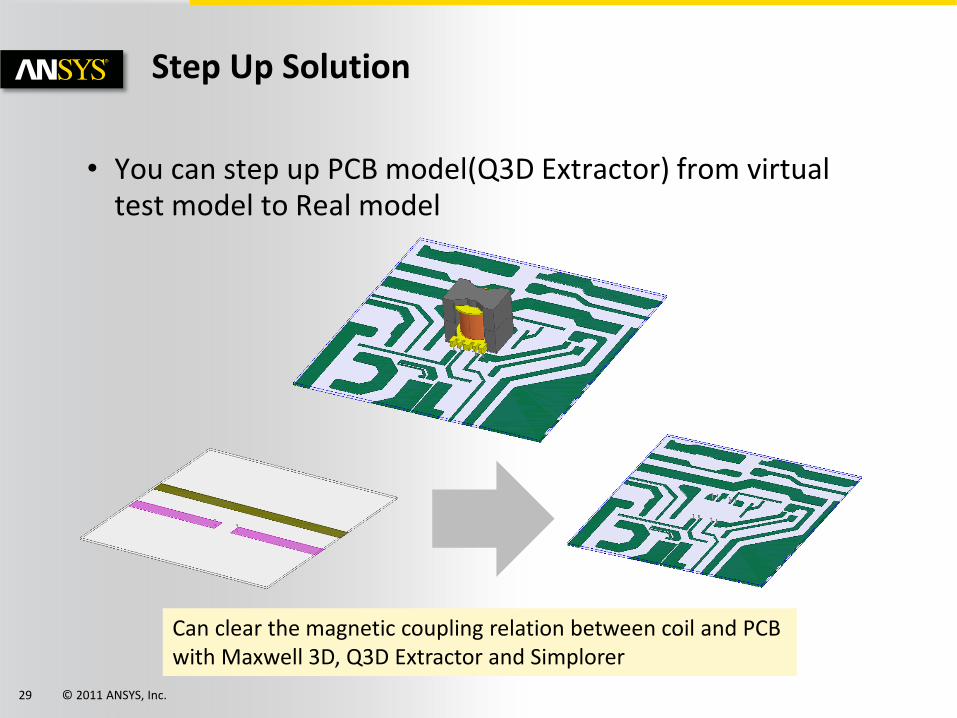
• You can step up PCB model(Q3D Extractor) from virtual test model to Real model
Step Up Solution
Can clear the magnetic coupling relation between coil and PCB with Maxwell 3D, Q3D Extractor and Simplorer