Embed Size (px)
Citation preview

Cisco APIC M3/L3 Server Installation and Service GuideFirst Published: 2018-10-25
Americas HeadquartersCisco Systems, Inc.170 West Tasman DriveSan Jose, CA 95134-1706USAhttp://www.cisco.comTel: 408 526-4000
800 553-NETS (6387)Fax: 408 527-0883

THE SPECIFICATIONS AND INFORMATION REGARDING THE PRODUCTS IN THIS MANUAL ARE SUBJECT TO CHANGE WITHOUT NOTICE. ALL STATEMENTS,INFORMATION, AND RECOMMENDATIONS IN THIS MANUAL ARE BELIEVED TO BE ACCURATE BUT ARE PRESENTED WITHOUT WARRANTY OF ANY KIND,EXPRESS OR IMPLIED. USERS MUST TAKE FULL RESPONSIBILITY FOR THEIR APPLICATION OF ANY PRODUCTS.
THE SOFTWARE LICENSE AND LIMITED WARRANTY FOR THE ACCOMPANYING PRODUCT ARE SET FORTH IN THE INFORMATION PACKET THAT SHIPPED WITHTHE PRODUCT AND ARE INCORPORATED HEREIN BY THIS REFERENCE. IF YOU ARE UNABLE TO LOCATE THE SOFTWARE LICENSE OR LIMITED WARRANTY,CONTACT YOUR CISCO REPRESENTATIVE FOR A COPY.
The following information is for FCC compliance of Class A devices: This equipment has been tested and found to comply with the limits for a Class A digital device, pursuant to part 15of the FCC rules. These limits are designed to provide reasonable protection against harmful interference when the equipment is operated in a commercial environment. This equipmentgenerates, uses, and can radiate radio-frequency energy and, if not installed and used in accordance with the instruction manual, may cause harmful interference to radio communications.Operation of this equipment in a residential area is likely to cause harmful interference, in which case users will be required to correct the interference at their own expense.
The following information is for FCC compliance of Class B devices: This equipment has been tested and found to comply with the limits for a Class B digital device, pursuant to part 15 ofthe FCC rules. These limits are designed to provide reasonable protection against harmful interference in a residential installation. This equipment generates, uses and can radiate radiofrequency energy and, if not installed and used in accordance with the instructions, may cause harmful interference to radio communications. However, there is no guarantee that interferencewill not occur in a particular installation. If the equipment causes interference to radio or television reception, which can be determined by turning the equipment off and on, users areencouraged to try to correct the interference by using one or more of the following measures:
• Reorient or relocate the receiving antenna.
• Increase the separation between the equipment and receiver.
• Connect the equipment into an outlet on a circuit different from that to which the receiver is connected.
• Consult the dealer or an experienced radio/TV technician for help.
Modifications to this product not authorized by Cisco could void the FCC approval and negate your authority to operate the product.
The Cisco implementation of TCP header compression is an adaptation of a program developed by the University of California, Berkeley (UCB) as part of UCB’s public domain version ofthe UNIX operating system. All rights reserved. Copyright © 1981, Regents of the University of California.
NOTWITHSTANDING ANY OTHERWARRANTY HEREIN, ALL DOCUMENT FILES AND SOFTWARE OF THESE SUPPLIERS ARE PROVIDED "AS IS" WITH ALL FAULTS.CISCO AND THE ABOVE-NAMED SUPPLIERS DISCLAIM ALL WARRANTIES, EXPRESSED OR IMPLIED, INCLUDING, WITHOUT LIMITATION, THOSE OFMERCHANTABILITY, FITNESS FOR A PARTICULAR PURPOSE AND NONINFRINGEMENT OR ARISING FROM A COURSE OF DEALING, USAGE, OR TRADE PRACTICE.
IN NO EVENT SHALL CISCO OR ITS SUPPLIERS BE LIABLE FOR ANY INDIRECT, SPECIAL, CONSEQUENTIAL, OR INCIDENTAL DAMAGES, INCLUDING, WITHOUTLIMITATION, LOST PROFITS OR LOSS OR DAMAGE TO DATA ARISING OUT OF THE USE OR INABILITY TO USE THIS MANUAL, EVEN IF CISCO OR ITS SUPPLIERSHAVE BEEN ADVISED OF THE POSSIBILITY OF SUCH DAMAGES.
Any Internet Protocol (IP) addresses and phone numbers used in this document are not intended to be actual addresses and phone numbers. Any examples, command display output, networktopology diagrams, and other figures included in the document are shown for illustrative purposes only. Any use of actual IP addresses or phone numbers in illustrative content is unintentionaland coincidental.
All printed copies and duplicate soft copies of this document are considered uncontrolled. See the current online version for the latest version.
Cisco has more than 200 offices worldwide. Addresses and phone numbers are listed on the Cisco website at www.cisco.com/go/offices.
Cisco and the Cisco logo are trademarks or registered trademarks of Cisco and/or its affiliates in the U.S. and other countries. To view a list of Cisco trademarks, go to this URL: www.cisco.comgo trademarks. Third-party trademarks mentioned are the property of their respective owners. The use of the word partner does not imply a partnership relationship between Cisco and anyother company. (1721R)
© 2018 Cisco Systems, Inc. All rights reserved.

C O N T E N T S
Overview 1C H A P T E R 1
Overview 1
External Features 1
Serviceable Component Locations 3
Summary of Server Features 5
Installing the Server 7C H A P T E R 2
Preparing for Installation 7
Installation Warnings and Guidelines 7
Grounding Requirements 9
Rack Requirements 9
Installing the Server in a Rack 10
Installing the Cable Management Arm (Optional) 12
Reversing the Cable Management Arm (Optional) 13
Initial Server Setup 14
Connecting to the Server Locally For Setup 15
Connecting to the Server Remotely For Setup 16
Setting Up the System With the Cisco IMC Configuration Utility 17
NIC Mode and NIC Redundancy Settings 19
Updating the BIOS and Cisco IMC Firmware 20
Accessing the System BIOS 20
Smart Access Serial 20
Smart Access USB 21
Maintaining the Server 23C H A P T E R 3
Status LEDs and Buttons 23
Cisco APIC M3/L3 Server Installation and Service Guideiii

Front-Panel LEDs 23
Rear-Panel LEDs 26
Internal Diagnostic LEDs 27
Preparing For Component Installation 28
Required Equipment For Service Procedures 29
Shutting Down and Removing Power From the Server 29
Shutting Down Using the Power Button 29
Shutting Down Using The Cisco IMC GUI 30
Shutting Down Using The Cisco IMC CLI 30
Removing the Server Top Cover 30
Serial Number Location 31
Hot Swap vs Hot Plug 31
Removing and Replacing Components 32
Serviceable Component Locations 32
Replacing SAS/SATA Hard Drives or Solid State Drives 34
SAS/SATA Drive Population Guidelines 34
4K Sector Format SAS/SATA Drives Considerations 34
Replacing a SAS/SATA Drive 35
Replacing a Front-Loading NVMe SSD 36
Front-Loading NVMe SSD Population Guidelines 36
Front-Loading NVME SSD Requirements and Restrictions 37
Enabling Hot-Plug Support in the System BIOS 37
Replacing a Front-Loading NVMe SSD 38
Installing a PCIe Cable For Front-Loading NVMe SSDs 39
Replacing HHHL Form-Factor NVMe Solid State Drives 40
HHHL SSD Population Guidelines 40
HHHL Form-Factor NVME SSD Requirements and Restrictions 40
Replacing an HHHL Form-Factor NVMe SSD 41
Replacing Fan Modules 42
Replacing Memory DIMMs 43
DIMM Population Rules and Memory Performance Guidelines 43
Replacing DIMMs 45
Replacing CPUs and Heatsinks 46
CPU Configuration Rules 46
Cisco APIC M3/L3 Server Installation and Service Guideiv
Contents
Tools Required For CPU Replacement 46
Replacing a CPU and Heatsink 47
Additional CPU-Related Parts to Order with RMA Replacement CPUs 53
Additional CPU-Related Parts to Order with RMA Replacement System Chassis 53
Moving an M5 Generation CPU 54
Replacing a Mini-Storage Module 59
Replacing a Mini-Storage Module Carrier 59
Replacing an SD Card in a Mini-Storage Carrier For SD 60
Replacing an M.2 SSD in a Mini-Storage Carrier For M.2 61
Replacing a Micro SD Card 61
Replacing an Internal USB Drive 63
Replacing a USB Drive 63
Enabling or Disabling the Internal USB Port 64
Replacing the RTC Battery 65
Replacing Power Supplies 66
Replacing AC Power Supplies 66
Replacing a PCIe Card 67
PCIe Slot Specifications 67
Replacing a PCIe Card 68
Cisco Virtual Interface Card (VIC) Considerations 70
Replacing an mLOM Card 71
Replacing an mRAID Riser (Riser 3) 72
Replacing a SAS Storage Controller Card (RAID or HBA) 74
Storage Controller Card Firmware Compatibility 74
Replacing a SAS Storage Controller Card (RAID or HBA) 75
Replacing the Supercap (RAID Backup) 76
Replacing a SATA Interposer Card 78
Replacing a Chassis Intrusion Switch 80
Installing a Trusted Platform Module (TPM) 81
TPM Considerations 81
Installing and Enabling a TPM 82
Service Headers and Jumpers 85
Using the Clear CMOS Header (J38, Pins 9 - 10) 86
Using the BIOS Recovery Header (J38, Pins 11 - 12) 86
Cisco APIC M3/L3 Server Installation and Service Guidev
Contents

Procedure 1: Reboot With recovery.cap File 87
Procedure 2: Use BIOS Recovery Header and bios.cap Recovery File 87
Using the Clear Password Header (J38, Pins 13 - 14) 88
Using the Boot Alternate Cisco IMC Image Header (J39, Pins 1 - 2) 89
Using the Reset Cisco IMC Password to Default Header (J39, Pins 3 - 4) 90
Using the Reset Cisco IMC to Defaults Header (J39, Pins 5 - 6) 90
Server Specifications 93A P P E N D I X A
Server Specifications 93
Physical Specifications 93
Environmental Specifications 93
Cisco Virtual Interface Card (VIC) Considerations 94
Power Specifications 95
770 W AC Power Supply 96
1050 W DC Power Supply 96
Power Cord Specifications 97
Storage Controller Considerations 101A P P E N D I X B
Supported Storage Controllers and Cables 101
Storage Controller Card Firmware Compatibility 102
Write-Cache Policy for Cisco 12G SAS Modular RAID Controller 103
Mixing Drive Types in RAID Groups 103
RAID Controller Migration 104
Storage Controller and Backplane Connectors 104
Embedded SATA RAID Controller 106
Embbeded SATA RAID Requirements 106
Embedded SATA RAID Controller Considerations 107
Embedded SATA RAID: Two SATA Controllers 107
Enabling SATA Mode For the Embedded Controllers 108
Accessing the Software RAID Configuration Utility 109
Installing LSI MegaSR Drivers For Windows and Linux 109
Downloading the MegaSR Drivers 109
Microsoft Windows Server Drivers 110
Linux Drivers 111
Cisco APIC M3/L3 Server Installation and Service Guidevi
Contents

For More RAID Utility Information 115
Cisco APIC M3/L3 Server Installation and Service Guidevii
Contents

Cisco APIC M3/L3 Server Installation and Service Guideviii
Contents
C H A P T E R 1Overview
• Overview, on page 1• External Features, on page 1• Serviceable Component Locations, on page 3• Summary of Server Features, on page 5
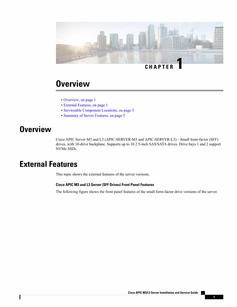
OverviewCisco APIC Server M3 and L3 (APIC-SERVER-M3 and APIC-SERVER-L3)—Small form-factor (SFF)drives, with 10-drive backplane. Supports up to 10 2.5-inch SAS/SATA drives. Drive bays 1 and 2 supportNVMe SSDs.
External FeaturesThis topic shows the external features of the server versions.
Cisco APIC M3 and L3 Server (SFF Drives) Front Panel Features
The following figure shows the front panel features of the small form-factor drive versions of the server.
Cisco APIC M3/L3 Server Installation and Service Guide1

Figure 1: Cisco APIC M3 and L3 Server (SFF Drives) Front Panel
Fan status LED7Drive bays 1 – 10 support SAS/SATA hard diskdrives (HDDs) and solid state drives (SSDs)
1
Network link activity LED8• APIC-Server-M3 and L3: Drive bays 1 and2 support NVMe PCIe SSDs.
2
Temperature status LED9Power button/power status LED3
Pull-out asset tag10Unit identification button/LED4
KVM connector
(used with KVM cable that provides one DB-15VGA, one DB-9 serial, and two USB connectors)
11System status LED5
-Power supply status LED6
Cisco APIC M3 and L3 Server Rear Panel Features
The rear panel features are the same for all versions of the server.
Cisco APIC M3/L3 Server Installation and Service Guide2
OverviewExternal Features

Figure 2: Cisco APIC M3 and L3 Server Rear Panel
Rear unit identification button/LED6USB 3.0 ports (two)1
Power supplies (two, redundant as 1+1)7Dual 1-Gb/10-Gb Ethernet ports (LAN1 andLAN2)
The dual LAN ports can support 1 Gbps and 10Gbps, depending on the link partner capability.
2
PCIe riser 1/slot 1 (x16 lane)8VGA video port (DB-15 connector)3
VIC 1455 with external 10/25-Gigabit Ethernet ports(4)
91-Gb Ethernet dedicated management port4
Threaded holes for dual-hole grounding lug10Serial port (RJ-45 connector)5
The VIC 1455 has 4 ports, port-1, port-2, port-3, and port-4 from left to right.Note
• All ports must have the same speed, either 10-Gigabit or 25-Gigabit.
• Port-1 and port-2 is one pair, corresponding to eth2-1 on APIC and port-3 and port-4 is another pair,corresponding to eth2-2 on APIC. Only one connection is allowed for each pair. For example, you canconnect one cable to either port-1 or port-2, and connect another cable to either port-3 or port-4 (pleasedo not connect two cables on any pair).
Serviceable Component LocationsThis topic shows the locations of the field-replaceable components and service-related items. The view in thefollowing figure shows the server with the top cover removed.
Cisco APIC M3/L3 Server Installation and Service Guide3
OverviewServiceable Component Locations
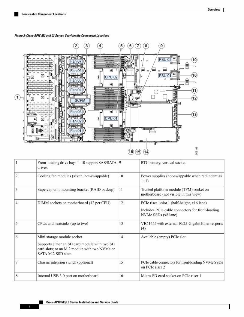
Figure 3: Cisco APIC M3 and L3 Server, Serviceable Component Locations
RTC battery, vertical socket9Front-loading drive bays 1–10 support SAS/SATAdrives.
1
Power supplies (hot-swappable when redundant as1+1)
10Cooling fan modules (seven, hot-swappable)2
Trusted platform module (TPM) socket onmotherboard (not visible in this view)
11Supercap unit mounting bracket (RAID backup)3
PCIe riser 1/slot 1 (half-height, x16 lane)
Includes PCIe cable connectors for front-loadingNVMe SSDs (x8 lane)
12DIMM sockets on motherboard (12 per CPU)4
VIC 1455 with external 10/25-Gigabit Ethernet ports(4)
13CPUs and heatsinks (up to two)5
Available (empty) PCIe slot14Mini storage module socket
Supports either an SD card module with two SDcard slots; or an M.2 module with two NVMe orSATA M.2 SSD slots.
6
PCIe cable connectors for front-loadingNVMeSSDson PCIe riser 2
15Chassis intrusion switch (optional)7
Micro-SD card socket on PCIe riser 116Internal USB 3.0 port on motherboard8
Cisco APIC M3/L3 Server Installation and Service Guide4
OverviewServiceable Component Locations

Summary of Server FeaturesThe following table lists a summary of server features.
DescriptionFeature
One rack-unit (1RU) chassisChassis
Up to two CPUs from the Intel Xeon Processor Scalable Family.This includes CPUs from the following series:
• Intel Xeon Bronze 3XXX Processors
• Intel Xeon Silver 4XXX Processors
• Intel Xeon Gold 5XXX Processors
• Intel Xeon Gold 6XXX Processors
• Intel Xeon Platinum 8XXX Processors
Central Processor
24 DDR4 DIMM sockets on the motherboard (12 each CPU)Memory
Multi-bit error protection is supportedMulti-bit error protection
BMC, running Cisco Integrated Management Controller (CiscoIMC) firmware.
Depending on your Cisco IMC settings, Cisco IMC can beaccessed through the 1-Gb dedicated management port, the1-Gb/10-Gb Ethernet LAN ports, or a Cisco virtual interface card.
Baseboard management
Rear panel:
• One 1-Gb Ethernet dedicated management port (RJ-45connector)
• Two 1-Gb/10-Gb BASE-T Ethernet LAN ports (RJ-45connectors)
The dual LAN ports can support 1 Gbps and 10 Gbps,depending on the link partner capability.
• One RS-232 serial port (RJ-45 connector)
• One VGA video connector port (DB-15 connector)
• Two USB 3.0 ports
Front panel:
• One front-panel keyboard/video/mouse (KVM) connectorthat is used with the KVM cable, which provides two USB2.0, one VGA, and one DB-9 serial connector.
Network and management I/O
Cisco APIC M3/L3 Server Installation and Service Guide5
OverviewSummary of Server Features

DescriptionFeature
One dedicated socket (x16 PCIe lane) that can be used to add anmLOM card for additional rear-panel connectivity.
Modular LOM
The two 1-Gb/10-Gb BASE-T Ethernet LAN ports support thewake-on-LAN (WoL) standard.
WoL
Two power supplies, redundant as 1+1:
• AC power supplies 770 W AC each
Power
The advanced configuration and power interface (ACPI) 4.0standard is supported.
ACPI
Seven hot-swappable fan modules for front-to-rear cooling.Cooling
Two horizontal PCIe expansion slots on a PCIe riser assembly.PCIe I/O
The PCIe bus slots in this server support the InfiniBandarchitecture.
InfiniBand
Cisco APIC M3 and L3 (APIC-SERVER-M3 andAPIC-SERVER-L3)—Small form-factor (SFF) drives, with10-drive backplane. Supports up to 10 2.5-inch SAS/SATA drives.Drive bays 1 and 2 support NVMe SSDs.
Storage, front-panel
The server has these internal storage options:
• One USB port on the motherboard.
• Mini-storage module socket, optionally with either:
• SD card module. Supports up to two SD cards.
• M.2 SSDmodule. Supports either two SATAM.2 SSDsor two NVMe M.2 SSDs.
• One micro-SD card socket on PCIe riser 1.
Storage, internal
The server has a dedicated internal mRAID riser that supportsone of the following storage-controller options:
• A PCIe-style Cisco modular RAID controller card(SAS/SATA).
• A PCIe-style interposer card for the server’s embeddedSATA RAID controller.
Storage management
The server has a mounting bracket near the cooling fans for thesupercap unit that is used with the Cisco modular RAID controllercard.
RAID backup
Integrated VGA video.Integrated video
Cisco APIC M3/L3 Server Installation and Service Guide6
OverviewSummary of Server Features
C H A P T E R 2Installing the Server
• Preparing for Installation, on page 7• Installing the Server in a Rack, on page 10• Initial Server Setup, on page 14• NIC Mode and NIC Redundancy Settings, on page 19• Updating the BIOS and Cisco IMC Firmware, on page 20• Accessing the System BIOS, on page 20• Smart Access Serial, on page 20• Smart Access USB, on page 21
Preparing for InstallationThis section contains the following topics:
Installation Warnings and Guidelines
Before you install, operate, or service a server, review the Regulatory Compliance and Safety Informationfor important safety information.
Note
IMPORTANT SAFETY INSTRUCTIONS
This warning symbol means danger. You are in a situation that could cause bodily injury. Before you workon any equipment, be aware of the hazards involved with electrical circuitry and be familiar with standardpractices for preventing accidents. Use the statement number provided at the end of each warning to locateits translation in the translated safety warnings that accompanied this device.
Statement 1071
Warning
Cisco APIC M3/L3 Server Installation and Service Guide7

To prevent the system from overheating, do not operate it in an area that exceeds the maximum recommendedambient temperature of: 35° C (95° F).
Statement 1047
Warning
The plug-socket combination must be accessible at all times, because it serves as the main disconnectingdevice.
Statement 1019
Warning
Installation of the equipment must comply with local and national electrical codes.
Statement 1074
Warning
This unit is intended for installation in restricted access areas. A restricted access area can be accessed onlythrough the use of a special tool, lock, and key, or other means of security.
Statement 1017
Warning
This product relies on the building's installation for short-circuit (over current) protection. Ensure that theprotective devices is rated not greater than 20A (North America), 16A (Europe),and 13A (UK).
Statement 1005
Warning
To ensure proper airflow it is necessary to rack the servers using rail kits. Physically placing the units on topof one another or “stacking” without the use of the rail kits blocks the air vents on top of the servers, whichcould result in overheating, higher fan speeds, and higher power consumption.We recommend that youmountyour servers on rail kits when you are installing them into the rack because these rails provide the minimalspacing required between the servers. No additional spacing between the servers is required when you mountthe units using rail kits.
Caution
Avoid uninterruptible power supply (UPS) types that use ferroresonant technology. These UPS types canbecome unstable with systems such as the Cisco UCS, which can have substantial current draw fluctuationsfrom fluctuating data traffic patterns.
Caution
To prevent loss of input power, ensure the total maximum loads on the circuits supplying power to the switchare within the current ratings for the wiring and breakers.
Caution
Cisco APIC M3/L3 Server Installation and Service Guide8
Installing the ServerInstallation Warnings and Guidelines
When you are installing a server, use the following guidelines:
• Plan your site configuration and prepare the site before installing the server.
• Ensure that there is adequate space around the server to allow for accessing the server and for adequateairflow. The airflow in this server is from front to back.
• Ensure that the air-conditioningmeets the thermal requirements listed in the Environmental Specifications,on page 93.
• Ensure that the cabinet or rack meets the requirements listed in the Rack Requirements, on page 9.
• Ensure that the site power meets the power requirements listed in the Power Specifications, on page 95.If available, you can use an uninterruptible power supply (UPS) to protect against power failures.
Grounding RequirementsThe switch is sensitive to variations in voltage supplied by the power sources. Overvoltage, undervoltage,and transients (or spikes) can erase data from memory or cause components to fail. To protect against thesetypes of problems, ensure that there is an earth-ground connection for the switch. You can connect the groundingpad on the switch either directly to the earth-ground connection or to a fully bonded and grounded rack.
When you properly install the chassis in a grounded rack, the switch is grounded because it has a metal-to-metalconnection to the rack. Alternatively, you can ground the chassis by using a customer-supplied groundingcable that meets your local and national installation requirements (we recommend 6-AWG wire for U.S.installations) connected to the chassis with a grounding lug (provided in the switch accessory kit) and to thefacility ground.
You automatically ground AC power supplies when you connect them to AC power sources. For DC powersupplies, you must connect a grounding wire when wiring the power supply to the DC power source.
Note
Rack RequirementsThe rack must be of the following type:
• A standard 19-in. (48.3-cm) wide, four-post EIA rack, with mounting posts that conform to Englishuniversal hole spacing, per section 1 of ANSI/EIA-310-D-1992.
• The rack-post holes can be square 0.38-inch (9.6 mm), round 0.28-inch (7.1 mm), #12-24 UNC, or #10-32UNC when you use the Cisco-supplied slide rails.
• The minimum vertical rack space per server must be one rack unit (RU), equal to 1.75 in. (44.45 mm).
Supported Cisco Slide Rail Kits
The server supports the following rail kit options:
Rack Installation Tools Required
The slide rails sold by Cisco Systems for this server do not require tools for installation.
Cisco APIC M3/L3 Server Installation and Service Guide9
Installing the ServerGrounding Requirements

Slide Rail and Cable Management Arm Dimensions
The slide rails for this server have an adjustment range of 24 to 36 inches (610 to 914 mm).
The optional cable management arm (CMA) adds additional length requirements:
• The additional distance from the rear of the server to the rear of the CMA is 5.4 inches (137.4 mm).
• The total length of the server including the CMA is 35.2 inches (894 mm).
Installing the Server in a Rack
To prevent bodily injury when mounting or servicing this unit in a rack, you must take special precautions toensure that the system remains stable. The following guidelines are provided to ensure your safety:
This unit should be mounted at the bottom of the rack if it is the only unit in the rack.
When mounting this unit in a partially filled rack, load the rack from the bottom to the top with the heaviestcomponent at the bottom of the rack.
If the rack is provided with stabilizing devices, install the stabilizers before mounting or servicing the unit inthe rack.
Statement 1006
Warning
Step 1 Attach the inner rails to the sides of the server:a) Align an inner rail with one side of the server so that the three keyed slots in the rail align with the three pegs on the
side of the server.b) Set the keyed slots over the pegs, and then slide the rail toward the front to lock it in place on the pegs. The front slot
has a metal clip that locks over the front peg.c) Install the second inner rail to the opposite side of the server.
Figure 4: Attaching the Inner Rail to the Side of the Server
Inner rail2Front of server1
Step 2 Open the front securing plate on both slide-rail assemblies. The front end of the slide-rail assembly has a spring-loadedsecuring plate that must be open before you can insert the mounting pegs into the rack-post holes.
On the outside of the assembly, push the green-arrow button toward the rear to open the securing plate.
Cisco APIC M3/L3 Server Installation and Service Guide10
Installing the ServerInstalling the Server in a Rack

Figure 5: Front Securing Mechanism, Inside of Front End
Securing plate shown pulled back to the openposition
3Front mounting pegs1
-Rack post betweenmounting pegs and openedsecuring plate
2
Step 3 Install the outer slide rails into the rack:a) Align one slide-rail assembly front end with the front rack-post holes that you want to use.
The slide rail front-end wraps around the outside of the rack post and the mounting pegs enter the rack-post holesfrom the outside-front.
The rack post must be between the mounting pegs and the open securing plate.Note
b) Push the mounting pegs into the rack-post holes from the outside-front.c) Press the securing plate release button, marked PUSH. The spring-loaded securing plate closes to lock the pegs in
place.d) Adjust the slide-rail length, and then push the rear mounting pegs into the corresponding rear rack-post holes. The
slide rail must be level front-to-rear.
The rear mounting pegs enter the rear rack-post holes from the inside of the rack post.
e) Attach the second slide-rail assembly to the opposite side of the rack. Ensure that the two slide-rail assemblies are atthe same height and are level front-to-back.
f) Pull the inner slide rails on each assembly out toward the rack front until they hit the internal stops and lock in place.
Step 4 Insert the server into the slide rails:
This server can weigh up to 64 pounds (29 kilograms) when fully loaded with components. We recommendthat you use a minimum of two people or a mechanical lift when lifting the server. Attempting this procedurealone could result in personal injury or equipment damage.
Caution
a) Align the rear ends of the inner rails that are attached to the server sides with the front ends of the empty slide railson the rack.
b) Push the inner rails into the slide rails on the rack until they stop at the internal stops.c) Slide the inner-rail release clip toward the rear on both inner rails, and then continue pushing the server into the rack
until its front slam-latches engage with the rack posts.
Cisco APIC M3/L3 Server Installation and Service Guide11
Installing the ServerInstalling the Server in a Rack

Figure 6: Inner-Rail Release Clip
Outer slide rail attached to rack post3Inner-rail release clip1
-Inner rail attached to server and inserted intoouter slide rail
2
Step 5 (Optional) Secure the server in the rack more permanently by using the two screws that are provided with the slide rails.Perform this step if you plan to move the rack with servers installed.
With the server fully pushed into the slide rails, open a hinged slam latch lever on the front of the server and insert ascrew through the hole that is under the lever. The screw threads into the static part of the rail on the rack post and preventsthe server from being pulled out. Repeat for the opposite slam latch.
Installing the Cable Management Arm (Optional)
The cable management arm (CMA) is reversible left-to-right. To reverse the CMA, see Reversing the CableManagement Arm (Optional), on page 13 before installation.
Note
Step 1 With the server pushed fully into the rack, slide the CMA tab of the CMA arm that is farthest from the server onto theend of the stationary slide rail that is attached to the rack post. Slide the tab over the end of the rail until it clicks andlocks.
Cisco APIC M3/L3 Server Installation and Service Guide12
Installing the ServerInstalling the Cable Management Arm (Optional)

Figure 7: Attaching the CMA to the Rear Ends of the Slide Rails
CMA tab on width-adjustment slider attachesto end of stationary outer slide rail.
3CMA tab on arm farthest from server attachesto end of stationary outer slide rail.
1
Rear of server4CMA tab on arm closest to the server attachesto end of inner slide rail attached to server.
2
Step 2 Slide the CMA tab that is closest to the server over the end of the inner rail that is attached to the server. Slide the tabover the end of the rail until it clicks and locks
Step 3 Pull out the width-adjustment slider that is at the opposite end of the CMA assembly until it matches the width of yourrack.
Step 4 Slide the CMA tab that is at the end of the width-adjustment slider onto the end of the stationary slide rail that is attachedto the rack post. Slide the tab over the end of the rail until it clicks and locks.
Step 5 Open the hinged flap at the top of each plastic cable guide and route your cables through the cable guides as desired.
Reversing the Cable Management Arm (Optional)
Step 1 Rotate the entire CMA assembly 180 degrees, left-to-right. The plastic cable guides must remain pointing upward.Step 2 Flip the tabs at the ends of the CMA arms so that they point toward the rear of the server.Step 3 Pivot the tab that is at the end of the width-adjustment slider. Depress and hold the metal button on the outside of the tab
and pivot the tab 180 degrees so that it points toward the rear of the server.
Cisco APIC M3/L3 Server Installation and Service Guide13
Installing the ServerReversing the Cable Management Arm (Optional)

Figure 8: Reversing the CMA
Metal button on outside of tab2CMA tab on end of width-adjustment slider1
Initial Server Setup
This section describes how to power on the server, assign an IP address, and connect to server managementwhen using the server in standalone mode.
Note
Server Default Settings
The server is shipped with these default settings:
• The NIC mode is Shared LOM EXT.
Shared LOM EXT mode enables the 1-Gb/10-Gb Ethernet ports and the ports on any installed Ciscovirtual interface card (VIC) to access the Cisco Integrated Management Interface (Cisco IMC). If youwant to use the 10/100/1000 dedicated management ports to access Cisco IMC, you can connect to theserver and change the NICmode as described in Setting Up the SystemWith the Cisco IMCConfigurationUtility, on page 17.
• The NIC redundancy is Active-Active. All Ethernet ports are utilized simultaneously.
• DHCP is enabled.
• IPv4 is enabled.
Cisco APIC M3/L3 Server Installation and Service Guide14
Installing the ServerInitial Server Setup

Connection Methods
There are two methods for connecting to the system for initial setup:
• Local setup—Use this procedure if you want to connect a keyboard and monitor directly to the systemfor setup. This procedure can use a KVM cable (Cisco PID N20-BKVM) or the ports on the rear of theserver.
• Remote setup—Use this procedure if you want to perform setup through your dedicated managementLAN.
To configure the system remotely, you must have a DHCP server on the samenetwork as the system. Your DHCP server must be preconfigured with the rangeof MAC addresses for this server node. The MAC address is printed on a labelthat is on the pull-out asset tag on the front panel. This server node has a rangeof six MAC addresses assigned to the Cisco IMC. The MAC address printed onthe label is the beginning of the range of six contiguous MAC addresses.
Note
This section contains the following topics:
Connecting to the Server Locally For SetupThis procedure requires the following equipment:
• VGA monitor
• USB keyboard
• Either the supported Cisco KVM cable (Cisco PID N20-BKVM); or a USB cable and VGADB-15 cable
Step 1 Attach a power cord to each power supply in your server, and then attach each power cord to a grounded power outlet.
Wait for approximately two minutes to let the server boot to standby power during the first bootup. You can verify systempower status by looking at the system Power Status LED on the front panel. The system is in standby power mode whenthe LED is amber.
Step 2 Connect a USB keyboard and VGA monitor to the server using one of the following methods:
• Connect an optional KVM cable (Cisco PID N20-BKVM) to the KVM connector on the front panel. Connect yourUSB keyboard and VGA monitor to the KVM cable.
• Connect a USB keyboard and VGA monitor to the corresponding connectors on the rear panel.
Step 3 Open the Cisco IMC Configuration Utility:a) Press and hold the front panel power button for four seconds to boot the server.b) During bootup, press F8 when prompted to open the Cisco IMC Configuration Utility.
The first time that you enter the Cisco IMC Configuration Utility, you are prompted to change the defaultpassword. The default password is password. The Strong Password feature is enabled.
Note
The following are the requirements for Strong Password:
Cisco APIC M3/L3 Server Installation and Service Guide15
Installing the ServerConnecting to the Server Locally For Setup

• The password can have minimum 8 characters; maximum 14 characters.
• The password must not contain the user’s name.
• The password must contain characters from three of the following four categories:
• English uppercase letters (A through Z)
• English lowercase letters (a through z)
• Base 10 digits (0 through 9)
• Non-alphabetic characters !, @, #, $, %, ^, &, *, -, _, =, “
Step 4 Continue with Setting Up the System With the Cisco IMC Configuration Utility, on page 17.
Connecting to the Server Remotely For SetupThis procedure requires the following equipment:
• One RJ-45 Ethernet cable that is connected to your management LAN.
Before you begin
To configure the system remotely, you must have a DHCP server on the same network as the system. YourDHCP server must be preconfigured with the range of MAC addresses for this server node. TheMAC addressis printed on a label that is on the pull-out asset tag on the front panel. This server node has a range of sixMAC addresses assigned to the Cisco IMC. The MAC address printed on the label is the beginning of therange of six contiguous MAC addresses.
Note
Step 1 Attach a power cord to each power supply in your server, and then attach each power cord to a grounded power outlet.
Wait for approximately two minutes to let the server boot to standby power during the first bootup. You can verify systempower status by looking at the system Power Status LED on the front panel. The system is in standby power mode whenthe LED is amber.
Step 2 Plug your management Ethernet cable into the dedicated management port on the rear panel.Step 3 Allow your preconfigured DHCP server to assign an IP address to the server node.Step 4 Use the assigned IP address to access and log in to the Cisco IMC for the server node. Consult with your DHCP server
administrator to determine the IP address.
The default user name for the server is admin. The default password is password.Note
Step 5 From the Cisco IMC Server Summary page, click Launch KVM Console. A separate KVM console window opens.Step 6 From the Cisco IMC Summary page, click Power Cycle Server. The system reboots.Step 7 Select the KVM console window.
The KVM console window must be the active window for the following keyboard actions to work.Note
Cisco APIC M3/L3 Server Installation and Service Guide16
Installing the ServerConnecting to the Server Remotely For Setup

Step 8 When prompted, press F8 to enter the Cisco IMC Configuration Utility. This utility opens in the KVM console window.
The first time that you enter the Cisco IMC Configuration Utility, you are prompted to change the defaultpassword. The default password is password. The Strong Password feature is enabled.
Note
The following are the requirements for Strong Password:
• The password can have minimum 8 characters; maximum 14 characters.
• The password must not contain the user’s name.
• The password must contain characters from three of the following four categories:
• English uppercase letters (A through Z)
• English lowercase letters (a through z)
• Base 10 digits (0 through 9)
• Non-alphabetic characters !, @, #, $, %, ^, &, *, -, _, =, “
Step 9 Continue with Setting Up the System With the Cisco IMC Configuration Utility, on page 17.
Setting Up the System With the Cisco IMC Configuration Utility
Before you begin
The following procedure is performed after you connect to the system and open the Cisco IMC ConfigurationUtility.
Step 1 Set the NIC mode to choose which ports to use to access Cisco IMC for server management:
• Shared LOMEXT (default)—This is the shared LOM extended mode, the factory-default setting. With this mode,the Shared LOM and Cisco Card interfaces are both enabled. You must select the default Active-Active NICredundancy setting in the following step.
In this NIC mode, DHCP replies are returned to both the shared LOM ports and the Cisco card ports. If the systemdetermines that the Cisco card connection is not getting its IP address from a Cisco UCSManager system becausethe server is in standalone mode, further DHCP requests from the Cisco card are disabled. Use the Cisco CardNIC mode if you want to connect to Cisco IMC through a Cisco card in standalone mode.
• Shared LOM—The 1-Gb/10-Gb Ethernet ports are used to access Cisco IMC. You must select either theActive-Active or Active-standby NIC redundancy setting in the following step.
• Dedicated—The dedicatedmanagement port is used to access Cisco IMC.Youmust select the NoneNIC redundancysetting in the following step.
• Cisco Card—The ports on an installed Cisco UCS Virtual Interface Card (VIC) are used to access the Cisco IMC.You must select either the Active-Active or Active-standby NIC redundancy setting in the following step.
See also the required VIC Slot setting below.
• VIC Slot—Only if you use the Cisco Card NIC mode, you must select this setting to match where your VIC isinstalled. The choices are Riser1, Riser2, or Flex-LOM (the mLOM slot).
Cisco APIC M3/L3 Server Installation and Service Guide17
Installing the ServerSetting Up the System With the Cisco IMC Configuration Utility
• If you select Riser1, you must install the VIC in slot 1.
• If you select Riser2, you must install the VIC in slot 2.
• If you select Flex-LOM, you must install an mLOM-style VIC in the mLOM slot.
Step 2 Set the NIC redundancy to your preference. This server has three possible NIC redundancy settings:
• None—The Ethernet ports operate independently and do not fail over if there is a problem. This setting can beused only with the Dedicated NIC mode.
• Active-standby—If an active Ethernet port fails, traffic fails over to a standby port. Shared LOM and Cisco Cardmodes can each use either Active-standby or Active-active settings.
• Active-active (default)—All Ethernet ports are utilized simultaneously. The Shared LOM EXT mode must useonly this NIC redundancy setting. Shared LOM and Cisco Card modes can each use either Active-standby orActive-active settings.
Step 3 Choose whether to enable DHCP for dynamic network settings, or to enter static network settings.
Before you enable DHCP, you must preconfigure your DHCP server with the range of MAC addresses forthis server. The MAC address is printed on a label on the rear of the server. This server has a range of sixMAC addresses assigned to Cisco IMC. The MAC address printed on the label is the beginning of the rangeof six contiguous MAC addresses.
Note
The static IPv4 and IPv6 settings include the following:
• The Cisco IMC IP address.
For IPv6, valid values are 1 - 127.
• The gateway.
For IPv6, if you do not know the gateway, you can set it as none by entering :: (two colons).
• The preferred DNS server address.
For IPv6, you can set this as none by entering :: (two colons).
Step 4 (Optional) Make VLAN settings.Step 5 Press F1 to go to the second settings window, then continue with the next step.
From the second window, you can press F2 to switch back to the first window.
Step 6 (Optional) Set a hostname for the server.Step 7 (Optional) Enable dynamic DNS and set a dynamic DNS (DDNS) domain.Step 8 (Optional) If you check the Factory Default check box, the server reverts to the factory defaults.Step 9 (Optional) Set a default user password.
The factory default username for the server is admin. The default password is password.Note
Step 10 (Optional) Enable auto-negotiation of port settings or set the port speed and duplex mode manually.
Auto-negotiation is applicable only when you use the Dedicated NIC mode. Auto-negotiation sets the portspeed and duplexmode automatically based on the switch port to which the server is connected. If you disableauto-negotiation, you must set the port speed and duplex mode manually.
Note
Cisco APIC M3/L3 Server Installation and Service Guide18
Installing the ServerSetting Up the System With the Cisco IMC Configuration Utility

Step 11 (Optional) Reset port profiles and the port name.Step 12 Press F5 to refresh the settings that you made. You might have to wait about 45 seconds until the new settings appear
and the message, “Network settings configured” is displayed before you reboot the server in the next step.Step 13 Press F10 to save your settings and reboot the server.
If you chose to enable DHCP, the dynamically assigned IP and MAC addresses are displayed on the consolescreen during bootup.
Note
What to do next
Use a browser and the IP address of the Cisco IMC to connect to the Cisco IMC management interface. TheIP address is based upon the settings that you made (either a static address or the address assigned by yourDHCP server).
The factory default username for the server is admin. The default password is password.Note
NIC Mode and NIC Redundancy SettingsTable 1: Valid NIC Redundancy Settings For Each NIC Mode
Valid NIC Redundancy SettingsNIC Mode
Active-activeShared LOMEXT
NoneDedicated
Active-active
Active-standby
Shared LOM
Active-active
Active-standby
Cisco Card
Only dedicated mode is supported.
Set the NIC mode to Dedicated, when setting up the CIMC, in the CIMC Configuration Utility. After theCIMC in configured, in the CIMC GUI, verify that you have the following parameters set.
SettingsParameters
Disabled on the VICLLDP
Enabled on the BIOSTPM Support
EnabledTPM Enabled Status
OwnedOwnership
Cisco APIC M3/L3 Server Installation and Service Guide19
Installing the ServerNIC Mode and NIC Redundancy Settings

Updating the BIOS and Cisco IMC Firmware
When you upgrade the BIOS firmware, you must also upgrade the Cisco IMC firmware to the same versionor the server does not boot. Do not power off the server until the BIOS and Cisco IMC firmware are matchingor the server does not boot.
Cisco provides the Cisco Host Upgrade Utility to assist with simultaneously upgrading the BIOS, Cisco IMC,and other firmware to compatible levels.
Caution
The server uses firmware obtained from and certified by Cisco. Cisco provides release notes with each firmwareimage. There are several possible methods for updating the firmware:
• Recommended method for firmware update: Use the Cisco Host Upgrade Utility to simultaneouslyupgrade the Cisco IMC, BIOS, and component firmware to compatible levels.
For the latest firmware release, see the Cisco Host Upgrade Utility Quick Reference Guide.
• You can upgrade the Cisco IMC and BIOS firmware by using the Cisco IMC GUI interface.
• You can upgrade the Cisco IMC and BIOS firmware by using the Cisco IMC CLI interface.
Accessing the System BIOS
Step 1 Enter the BIOS Setup Utility by pressing the F2 key when prompted during bootup.
The version and build of the current BIOS are displayed on the Main page of the utility.Note
Step 2 Use the arrow keys to select the BIOS menu page.Step 3 Highlight the field to be modified by using the arrow keys.Step 4 Press Enter to select the field that you want to change, and then modify the value in the field.Step 5 Press the right arrow key until the Exit menu screen is displayed.Step 6 Follow the instructions on the Exit menu screen to save your changes and exit the setup utility (or press F10). You can
exit without saving changes by pressing Esc.
Smart Access SerialThis server supports the Smart Access Serial feature. This feature allows you to switch between host serialand Cisco IMC CLI.
• This feature has the following requirements:
• A serial cable connection, which can use either the RJ-45 serial connector on the server rear panel,or a DB-9 connection when using the KVM cable (Cisco PIDN20-BKVM) on the front-panel KVMconsole connector.
Cisco APIC M3/L3 Server Installation and Service Guide20
Installing the ServerUpdating the BIOS and Cisco IMC Firmware

• Console redirection must be enabled in the server BIOS.
• Terminal type must be set to VT100+ or VTUFT8.
• Serial-over-LAN (SOL) must be disabled (SOL is disabled by default).
• To switch from host serial to Cisco IMC CLI, press Esc+9.
You must enter your Cisco IMC credentials to authenticate the connection.
• To switch from Cisco IMC CLI to host serial, press Esc+8.
You cannot switch to Cisco IMC CLI if the serial-over-LAN (SOL) feature isenabled.
Note
• After a session is created, it is shown in the CLI or web GUI by the name serial.
Smart Access USBThis server supports the Smart Access USB feature. The board management controller (BMC) in this servercan accept a USB mass storage device and access the data on it. This feature allows you to use the front-panelUSB device as a medium to transfer data between the BMC and the user without need for network connectivity.This can be useful, for example, when remote BMC interfaces are not yet available, or are not accessible dueto network misconfiguration.
• This feature has the following requirements:
• The KVM cable (Cisco PID N20-BKVM) connected to the front panel KVM console connector.
• A USB storage device connected to one of the USB 2.0 connectors on the KVM cable. The USBdevice must draw less than 500 mA to avoid disconnect by the current-protection circuit.
Anymouse or keyboard that is connected to the KVM cable is disconnected whenyou enable Smart Access USB.
Note
• You can use USB 3.0-based devices, but they will operate at USB 2.0 speed.
• We recommend that the USB device have only one partition.
• The file system formats supported are: FAT16, FAT32, MSDOS, EXT2, EXT3, and EXT4. NTFSis not supported.
• The front-panel KVM connector has been designed to switch the USB port between Host OS and BMC.
• Smart Access USB can be enabled or disabled using any of the BMC user interfaces. For example, youcan use the Cisco IMC Configuration Utility that is accessed by pressing F8 when prompted duringbootup.
• Enabled: the front-panel USB device is connected to the BMC.
Cisco APIC M3/L3 Server Installation and Service Guide21
Installing the ServerSmart Access USB

• Disabled: the front-panel USB device is connected to the host.
• In a case where nomanagement network is available to connect remotely to Cisco IMC, a Device FirmwareUpdate (DFU) shell over serial cable can be used to generate and download technical support files to theUSB device that is attached to front panel USB port.
Cisco APIC M3/L3 Server Installation and Service Guide22
Installing the ServerSmart Access USB

C H A P T E R 3Maintaining the Server
• Status LEDs and Buttons, on page 23• Preparing For Component Installation, on page 28• Removing and Replacing Components, on page 32• Service Headers and Jumpers, on page 85
Status LEDs and ButtonsThis section contains information for interpreting front, rear, and internal LED states.
Front-Panel LEDsFigure 9: Front Panel LEDs
Table 2: Front Panel LEDs, Definition of States
StatesLED Name
Cisco APIC M3/L3 Server Installation and Service Guide23

• Off—The hard drive is operating properly.
• Amber—Drive fault detected.
• Amber, blinking—The device is rebuilding.
• Amber, blinking with one-second interval—Drivelocate function activated in the software.
SAS/SATA drive fault
NVMe solid state drive (SSD) drive trayLEDs have different behavior thanSAS/SATA drive trays.
Note
1
SAS
• Off—There is no hard drive in the hard drive tray (noaccess, no fault).
• Green—The hard drive is ready.
• Green, blinking—The hard drive is reading or writingdata.
SAS/SATA drive activity LED2
SAS
• Off—The drive is not in use and can be safelyremoved.
• Green—The drive is in use and functioning properly.
• Green, blinking—the driver is initializing followinginsertion or the driver is unloading following an ejectcommand.
• Amber—The drive has failed.
• Amber, blinking—Adrive Locate command has beenissued in the software.
NVMe SSD drive fault
NVMe solid state drive (SSD) drive trayLEDs have different behavior thanSAS/SATA drive trays.
Note
1
NVMe
• Off—No drive activity.
• Green, blinking—There is drive activity.
NVMe SSD activity2
NVMe
• Off—There is no AC power to the server.
• Amber—The server is in standby power mode. Poweris supplied only to the Cisco IMC and somemotherboard functions.
• Green—The server is in main power mode. Power issupplied to all server components.
Power button/LED3
• Off—The unit identification function is not in use.
• Blue, blinking—The unit identification function isactivated.
Unit identification4
Cisco APIC M3/L3 Server Installation and Service Guide24
Maintaining the ServerFront-Panel LEDs

• Green—The server is running in normal operatingcondition.
• Green, blinking—The server is performing systeminitialization and memory check.
• Amber, steady—The server is in a degradedoperational state (minor fault). For example:
• Power supply redundancy is lost.
• CPUs are mismatched.
• At least one CPU is faulty.
• At least one DIMM is faulty.
• At least one drive in a RAID configuration failed.
• Amber, 2 blinks—There is a major fault with thesystem board.
• Amber, 3 blinks—There is a major fault with thememory DIMMs.
• Amber, 4 blinks—There is a major fault with theCPUs.
System health5
• Green—All power supplies are operating normally.
• Amber, steady—One or more power supplies are ina degraded operational state.
• Amber, blinking—One or more power supplies arein a critical fault state.
Power supply status6
• Green—All fan modules are operating properly.
• Amber, blinking—One or more fanmodules breachedthe non-recoverable threshold.
Fan status7
• Off—The Ethernet LOM port link is idle.
• Green—One or more Ethernet LOM ports arelink-active, but there is no activity.
• Green, blinking—One or more Ethernet LOM portsare link-active, with activity.
Network link activity8
• Green—The server is operating at normal temperature.
• Amber, steady—One or more temperature sensorsbreached the critical threshold.
• Amber, blinking—One or more temperature sensorsbreached the non-recoverable threshold.
Temperature status9
Cisco APIC M3/L3 Server Installation and Service Guide25
Maintaining the ServerFront-Panel LEDs

Rear-Panel LEDsFigure 10: Rear Panel LEDs
Table 3: Rear Panel LEDs, Definition of States
StatesLED Name
• Off—Link speed is 100 Mbps.
• Amber—Link speed is 1 Gbps.
• Green—Link speed is 10 Gbps.
1-Gb/10-Gb Ethernet link speed (on both LAN1 andLAN2)
1
• Off—No link is present.
• Green—Link is active.
• Green, blinking—Traffic is present on the active link.
1-Gb/10-Gb Ethernet link status (on both LAN1 andLAN2)
2
• Off—Link speed is 10 Mbps.
• Amber—Link speed is 100 Mbps.
• Green—Link speed is 1 Gbps.
1-Gb Ethernet dedicated management link speed3
• Off—No link is present.
• Green—Link is active.
• Green, blinking—Traffic is present on the active link.
1-Gb Ethernet dedicated management link status4
• Off—The unit identification function is not in use.
• Blue, blinking—The unit identification function isactivated.
Rear unit identification5
Cisco APIC M3/L3 Server Installation and Service Guide26
Maintaining the ServerRear-Panel LEDs

AC power supplies:
• Off—No AC input (12 V main power off, 12 Vstandby power off).
• Green, blinking—12Vmain power off; 12 V standbypower on.
• Green, solid—12 V main power on; 12 V standbypower on.
• Amber, blinking—Warning threshold detected but 12V main power on.
• Amber, solid—Critical error detected; 12 V mainpower off (for example, over-current, over-voltage,or over-temperature failure).
DC power supplies:
• Off—No DC input (12 V main power off, 12 Vstandby power off).
• Green, blinking—12Vmain power off; 12 V standbypower on.
• Green, solid—12 V main power on; 12 V standbypower on.
• Amber, blinking—Warning threshold detected but 12V main power on.
• Amber, solid—Critical error detected; 12 V mainpower off (for example, over-current, over-voltage,or over-temperature failure).
Power supply status (one LED each power supply unit)6
Internal Diagnostic LEDsThe server has internal fault LEDs for CPUs, DIMMs, and fan modules.
Cisco APIC M3/L3 Server Installation and Service Guide27
Maintaining the ServerInternal Diagnostic LEDs

Figure 11: Internal Diagnostic LED Locations
DIMM fault LEDs (one behind each DIMM socketon the motherboard)
These LEDs operate only when the server is instandby power mode.
• Amber—DIMM has a fault.
• Off—DIMM is OK.
3Fan module fault LEDs (one behind each fanconnector on the motherboard)
• Amber—Fan has a fault or is not fully seated.
• Green—Fan is OK.
1
-CPU fault LEDs (one behind each CPU socket onthe motherboard).
These LEDs operate only when the server is instandby power mode.
• Amber—CPU has a fault.
• Off—CPU is OK.
2
Preparing For Component InstallationThis section includes information and tasks that help prepare the server for component installation.
Cisco APIC M3/L3 Server Installation and Service Guide28
Maintaining the ServerPreparing For Component Installation

Required Equipment For Service ProceduresThe following tools and equipment are used to perform the procedures in this chapter:
• T-30 Torx driver (supplied with replacement CPUs for heatsink removal)
• #1 flat-head screwdriver (supplied with replacement CPUs for heatsink removal)
• #1 Phillips-head screwdriver (for M.2 SSD and intrusion switch replacement)
• Electrostatic discharge (ESD) strap or other grounding equipment such as a grounded mat
Shutting Down and Removing Power From the ServerThe server can run in either of two power modes:
• Main power mode—Power is supplied to all server components and any operating system on your drivescan run.
• Standby power mode—Power is supplied only to the service processor and certain components. It is safefor the operating system and data to remove power cords from the server in this mode.
After a server is shut down to standby power, electric current is still present in the server. To completelyremove power as directed in some service procedures, you must disconnect all power cords from all powersupplies in the server.
Caution
You can shut down the server by using the front-panel power button or the software management interfaces.
Shutting Down Using the Power Button
Step 1 Check the color of the Power button/LED:
• Amber—The server is already in standby mode and you can safely remove power.
• Green—The server is in main power mode and must be shut down before you can safely remove power.
Step 2 Invoke either a graceful shutdown or a hard shutdown:
To avoid data loss or damage to your operating system, you should always invoke a graceful shutdown of theoperating system.
Caution
• Graceful shutdown—Press and release the Power button. The operating system performs a graceful shutdown andthe server goes to standby mode, which is indicated by an amber Power button/LED.
• Emergency shutdown—Press and hold the Power button for 4 seconds to force the main power off and immediatelyenter standby mode.
Step 3 If a service procedure instructs you to completely remove power from the server, disconnect all power cords from thepower supplies in the server.
Cisco APIC M3/L3 Server Installation and Service Guide29
Maintaining the ServerRequired Equipment For Service Procedures

Shutting Down Using The Cisco IMC GUIYou must log in with user or admin privileges to perform this task.
Step 1 In the Navigation pane, click the Server tab.Step 2 On the Server tab, click Summary.Step 3 In the Actions area, click Power Off Server.Step 4 Click OK.
The operating system performs a graceful shutdown and the server goes to standby mode, which is indicated by an amberPower button/LED.
Step 5 If a service procedure instructs you to completely remove power from the server, disconnect all power cords from thepower supplies in the server.
Shutting Down Using The Cisco IMC CLIYou must log in with user or admin privileges to perform this task.
Step 1 At the server prompt, enter:
Example:
server# scope chassisStep 2 At the chassis prompt, enter:
Example:
server/chassis# power shutdown
The operating system performs a graceful shutdown and the server goes to standby mode, which is indicated by an amberPower button/LED.
Step 3 If a service procedure instructs you to completely remove power from the server, disconnect all power cords from thepower supplies in the server.
Removing the Server Top Cover
Step 1 Remove the top cover:a) If the cover latch is locked, use a screwdriver to turn the lock 90-degrees counterclockwise to unlock it.b) Lift on the end of the latch that has the green finger grip. The cover is pushed back to the open position as you lift
the latch.c) Lift the top cover straight up from the server and set it aside.
Step 2 Replace the top cover:a) With the latch in the fully open position, place the cover on top of the server about one-half inch (1.27 cm) behind
the lip of the front cover panel. The opening in the latch should fit over the peg that sticks up from the fan tray.
Cisco APIC M3/L3 Server Installation and Service Guide30
Maintaining the ServerShutting Down Using The Cisco IMC GUI

b) Press the cover latch down to the closed position. The cover is pushed forward to the closed position as you pushdown the latch.
c) If desired, lock the latch by using a screwdriver to turn the lock 90-degrees clockwise.
Figure 12: Removing the Top Cover
Locking cover latch2Top cover1
Serial number label location3
Serial Number LocationThe serial number for the server is printed on a label on the top of the server, near the front.
Hot Swap vs Hot PlugSome components can be removed and replaced without shutting down and removing power from the server.This type of replacement has two varieties: hot-swap and hot-plug.
Cisco APIC M3/L3 Server Installation and Service Guide31
Maintaining the ServerSerial Number Location

• Hot-swap replacement—You do not have to shut down the component in the software or operatingsystem. This applies to the following components:
• SAS/SATA hard drives
• SAS/SATA solid state drives
• Cooling fan modules
• Power supplies (when redundant as 1+1)
• Hot-plug replacement—You must take the component offline before removing it for the followingcomponent:
• NVMe PCIe solid state drives
Removing and Replacing Components
Blank faceplates and cover panels serve three important functions: they prevent exposure to hazardous voltagesand currents inside the chassis; they contain electromagnetic interference (EMI) that might disrupt otherequipment; and they direct the flow of cooling air through the chassis. Do not operate the system unless allcards, faceplates, front covers, and rear covers are in place.
Statement 1029
Warning
When handling server components, handle them only by carrier edges and use an electrostatic discharge (ESD)wrist-strap or other grounding device to avoid damage.
Caution
You can press the unit identification button on the front panel or rear panel to turn on a flashing, blue unitidentification LED on both the front and rear panels of the server. This button allows you to locate the specificserver that you are servicing when you go to the opposite side of the rack. You can also activate these LEDsremotely by using the Cisco IMC interface.
Tip
This section describes how to install and replace server components.
Serviceable Component LocationsThis topic shows the locations of the field-replaceable components and service-related items. The view in thefollowing figure shows the server with the top cover removed.
Cisco APIC M3/L3 Server Installation and Service Guide32
Maintaining the ServerRemoving and Replacing Components

Figure 13: Cisco APIC M3 and L3 Server, Serviceable Component Locations
RTC battery, vertical socket9Front-loading drive bays 1–10 support SAS/SATAdrives.
1
Power supplies (hot-swappable when redundant as1+1)
10Cooling fan modules (seven, hot-swappable)2
Trusted platform module (TPM) socket onmotherboard (not visible in this view)
11Supercap unit mounting bracket (RAID backup)3
PCIe riser 1/slot 1 (half-height, x16 lane)
Includes PCIe cable connectors for front-loadingNVMe SSDs (x8 lane)
12DIMM sockets on motherboard (12 per CPU)4
VIC 1455 with external 10/25-Gigabit Ethernet ports(4)
13CPUs and heatsinks (up to two)5
Available (empty) PCIe slot14Mini storage module socket
Supports either an SD card module with two SDcard slots; or an M.2 module with two NVMe orSATA M.2 SSD slots.
6
PCIe cable connectors for front-loadingNVMeSSDson PCIe riser 2
15Chassis intrusion switch (optional)7
Micro-SD card socket on PCIe riser 116Internal USB 3.0 port on motherboard8
Cisco APIC M3/L3 Server Installation and Service Guide33
Maintaining the ServerServiceable Component Locations

Replacing SAS/SATA Hard Drives or Solid State Drives
You do not have to shut down the server or drive to replace SAS/SATA hard drives or SSDs because theyare hot-swappable. To replace an NVMe PCIe SSD drive, which must be shut down before removal, seeReplacing a Front-Loading NVMe SSD, on page 36.
Note
SAS/SATA Drive Population GuidelinesThe server is orderable in three different versions, each with a different front panel/drive-backplaneconfiguration.
Drive bay numbering is shown in the following figures.
Figure 14: Small Form-Factor Drive Versions, Drive Bay Numbering
Observe these drive population guidelines for optimum performance:
• When populating drives, add drives to the lowest-numbered bays first.
For diagrams of which drive bays are controlled by particular controller cableson the backplane, see Storage Controller and Backplane Connectors, on page 104.For example, in a SFF 10-drive server, drive bays 5 and 10 cannot be controlledby embedded SATA RAID.
Note
• Keep an empty drive blanking tray in any unused bays to ensure proper airflow.
• You can mix SAS/SATA hard drives and SAS/SATA SSDs in the same server. However, you cannotconfigure a logical volume (virtual drive) that contains a mix of hard drives and SSDs. That is, whenyou create a logical volume, it must contain all SAS/SATA hard drives or all SAS/SATA SSDs.
4K Sector Format SAS/SATA Drives Considerations• You must boot 4K sector format drives in UEFI mode, not legacy mode. See the procedures in thissection.
• Do not configure 4K sector format and 512-byte sector format drives as part of the same RAID volume.
• Operating system support on 4K sector drives is as follows:Windows:Win2012 andWin2012R2; Linux:RHEL 6.5, 6.6, 6.7, 7.0, 7.2; SLES 11 SP3, and SLES 12. ESXi/Vmware is not supported.
Procedure
PurposeCommand or Action
Step 1
Cisco APIC M3/L3 Server Installation and Service Guide34
Maintaining the ServerReplacing SAS/SATA Hard Drives or Solid State Drives

Setting Up UEFI Mode Booting in the BIOS Setup Utility
Step 1 Enter the BIOS setup utility by pressing the F2 key when prompted during bootup.Step 2 Go to the Boot Options tab.Step 3 Set UEFI Boot Options to Enabled.Step 4 Under Boot Option Priorities, set your OS installation media (such as a virtual DVD) as your Boot Option #1.Step 5 Go to the Advanced tab.Step 6 Select LOM and PCIe Slot Configuration.Step 7 Set the PCIe Slot ID: HBA Option ROM to UEFI Only.Step 8 Press F10 to save changes and exit the BIOS setup utility. Allow the server to reboot.Step 9 After the OS installs, verify the installation:
a) Enter the BIOS setup utility by pressing the F2 key when prompted during bootup.b) Go to the Boot Options tab.c) Under Boot Option Priorities, verify that the OS you installed is listed as your Boot Option #1.
Setting Up UEFI Mode Booting in the Cisco IMC GUI
Step 1 Use a web browser and the IP address of the server to log into the Cisco IMC GUI management interface.Step 2 Navigate to Server > BIOS.Step 3 Under Actions, click Configure BIOS.Step 4 In the Configure BIOS Parameters dialog, select the Advanced tab.Step 5 Go to the LOM and PCIe Slot Configuration section.Step 6 Set the PCIe Slot: HBA Option ROM to UEFI Only.Step 7 Click Save Changes. The dialog closes.Step 8 Under BIOS Properties, set Configured Boot Order to UEFI.Step 9 Under Actions, click Configure Boot Order.Step 10 In the Configure Boot Order dialog, click Add Local HDD.Step 11 In the Add Local HDD dialog, enter the information for the 4K sector format drive and make it first in the boot order.Step 12 Save changes and reboot the server. The changes you made will be visible after the system reboots.
Replacing a SAS/SATA Drive
Step 1 Remove the drive that you are replacing or remove a blank drive tray from the bay:a) Press the release button on the face of the drive tray.b) Grasp and open the ejector lever and then pull the drive tray out of the slot.c) If you are replacing an existing drive, remove the four drive-tray screws that secure the drive to the tray and then lift
the drive out of the tray.
Step 2 Install a new drive:a) Place a new drive in the empty drive tray and install the four drive-tray screws.
Cisco APIC M3/L3 Server Installation and Service Guide35
Maintaining the ServerSetting Up UEFI Mode Booting in the BIOS Setup Utility
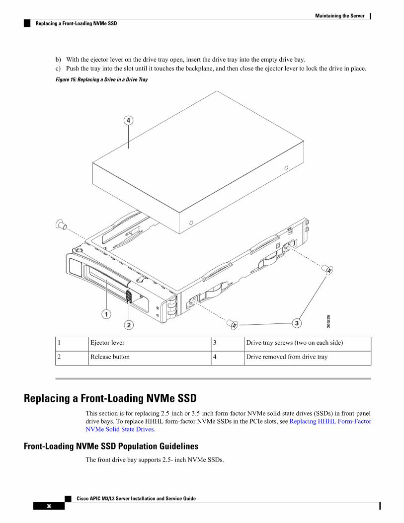
b) With the ejector lever on the drive tray open, insert the drive tray into the empty drive bay.c) Push the tray into the slot until it touches the backplane, and then close the ejector lever to lock the drive in place.
Figure 15: Replacing a Drive in a Drive Tray
Drive tray screws (two on each side)3Ejector lever1
Drive removed from drive tray4Release button2
Replacing a Front-Loading NVMe SSDThis section is for replacing 2.5-inch or 3.5-inch form-factor NVMe solid-state drives (SSDs) in front-paneldrive bays. To replace HHHL form-factor NVMe SSDs in the PCIe slots, see Replacing HHHL Form-FactorNVMe Solid State Drives.
Front-Loading NVMe SSD Population GuidelinesThe front drive bay supports 2.5- inch NVMe SSDs.
Cisco APIC M3/L3 Server Installation and Service Guide36
Maintaining the ServerReplacing a Front-Loading NVMe SSD

Front-Loading NVME SSD Requirements and RestrictionsObserve these requirements:
• The server must have two CPUs. PCIe riser 2 is not available in a single-CPU system. PCIe riser 2 hasconnectors for the cable that connects to the front-panel drive backplane.
• PCIe cable CBL-NVME-C220FF. This is the cable that carries the PCIe signal from the front-panel drivebackplane to PCIe riser 2. This cable is for all versions of this server.
• Hot-plug support must be enabled in the system BIOS. If you ordered the system with NVMe drives,hot-plug support is enabled at the factory.
• The NVMe-optimized, SFF 10-drive version, APIC-SERVER-M3 and APIC-SERVER-L3, supportNVMe drives only. This version of the server comes with an NVMe-switch card factory-installed in theinternal mRAID riser for support of NVMe drives in slots 3 - 10. The NVMe drives in slots 1 and 2 aresupported by PCIe riser 2. The NVMe switch card is not orderable separately.
Observe these restrictions:
• NVMe SFF 2.5-inch SSDs support booting only in UEFI mode. Legacy boot is not supported.
• You cannot control NVMe PCIe SSDs with a SAS RAID controller because NVMe SSDs interface withthe server via the PCIe bus.
• UEFI boot is supported in all supported operating systems. Hot-insertion and hot-removal are supportedin all supported operating systems except VMWare ESXi.
Enabling Hot-Plug Support in the System BIOSHot-plug (OS-informed hot-insertion and hot-removal) is disabled in the system BIOS by default.
• If the system was ordered with NVMe PCIe SSDs, the setting was enabled at the factory. No action isrequired.
• If you are adding NVMe PCIe SSDs after-factory, you must enable hot-plug support in the BIOS. Seethe following procedures.
Enabling Hot-Plug Support Using the BIOS Setup Utility
Step 1 Enter the BIOS setup utility by pressing the F2 key when prompted during bootup.Step 2 Navigate to Advanced > PCI Subsystem Settings > NVMe SSD Hot-Plug Support.Step 3 Set the value to Enabled.Step 4 Save your changes and exit the utility.
Enabling Hot-Plug Support Using the Cisco IMC GUI
Step 1 Use a browser to log in to the Cisco IMC GUI for the server.Step 2 Navigate to Compute > BIOS > Advanced > PCI Configuration.Step 3 Set NVME SSD Hot-Plug Support to Enabled.
Cisco APIC M3/L3 Server Installation and Service Guide37
Maintaining the ServerFront-Loading NVME SSD Requirements and Restrictions

Step 4 Save your changes.
Replacing a Front-Loading NVMe SSDThis topic describes how to replace 2.5-inch form-factor NVMe SSDs in the front-panel drive bays.
OS-surprise removal is not supported. OS-informed hot-insertion and hot-removal are supported on allsupported operating systems except VMware ESXi.
Note
OS-informed hot-insertion and hot-removal must be enabled in the system BIOS. See Enabling Hot-PlugSupport in the System BIOS, on page 37.
Note
Step 1 Remove an existing front-loading NVMe SSD:a) Shut down the NVMe SSD to initiate an OS-informed removal. Use your operating system interface to shut down
the drive, and then observe the drive-tray LED:
• Green—The drive is in use and functioning properly. Do not remove.
• Green, blinking—the driver is unloading following a shutdown command. Do not remove.
• Off—The drive is not in use and can be safely removed.
b) Press the release button on the face of the drive tray.c) Grasp and open the ejector lever and then pull the drive tray out of the slot.d) Remove the four drive tray screws that secure the SSD to the tray and then lift the SSD out of the tray.
If this is the first time that front-loading NVMe SSDs are being installed in the server, you must install PCIecable CBL-NVME-C220FF before installing the drive.
Note
Step 2 Install a new front-loading NVMe SSD:a) Place a new SSD in the empty drive tray and install the four drive-tray screws.b) With the ejector lever on the drive tray open, insert the drive tray into the empty drive bay.c) Push the tray into the slot until it touches the backplane, and then close the ejector lever to lock the drive in place.
Step 3 Observe the drive-tray LED and wait until it returns to solid green before accessing the drive:
• Off—The drive is not in use.
• Green, blinking—the driver is initializing following hot-plug insertion.
• Green—The drive is in use and functioning properly.
Cisco APIC M3/L3 Server Installation and Service Guide38
Maintaining the ServerReplacing a Front-Loading NVMe SSD

Figure 16: Replacing a Drive in a Drive Tray
Drive tray screws (two on each side)3Ejector lever1
Drive removed from drive tray4Release button2
Installing a PCIe Cable For Front-Loading NVMe SSDsThe front-loading NVMe SSDs interface with the server via the PCIe bus. Cable CBL-NVME-C220FFconnects the front-panel drive backplane to the PCIe riser 2 board on the PCIe riser assembly.
• If the server was ordered with 2.5-inch form-factor NVMe SSDs, this cable was preinstalled at the factory.No action is required.
• If you are adding 2.5-inch form-factor NVMe SSDs for the first time, you must order and install thecable as described in the following procedure.
Cisco APIC M3/L3 Server Installation and Service Guide39
Maintaining the ServerInstalling a PCIe Cable For Front-Loading NVMe SSDs

Step 1 Connect the two connectors on one end of the cable to the PCIE-A1 and PCIE-A2 connectors on the drive backplane.Step 2 Route the cables through the chassis cable guides to the rear of the server as shown below.Step 3 Connect the single connector on the other end of the cable to the PCIE-FRONT connector on PCIe riser 2.
Figure 17: PCIe Cabling to Drive Backplane
Replacing HHHL Form-Factor NVMe Solid State DrivesThis section is for replacing half-height, half-length (HHHL) form-factor NVMe SSDs in the PCIe slots. Toreplace 2.5-inch NVMe SSDs in the front-panel drive bays, see Replacing a Front-Loading NVMe SSD, onpage 36.
HHHL SSD Population GuidelinesObserve the following population guidelines when installing HHHL form-factor NVMe SSDs:
• Two-CPU systems—You can populate up to 2 HHHL form-factor SSDs, using PCIe slots 1 – 2.
• One-CPU systems—In a single-CPU system, PCIe riser 2/slot 2 is not available. Therefore, the maximumnumber of HHHL form-factor SSDs you can populate is 1, in PCIe slot 1.
HHHL Form-Factor NVME SSD Requirements and RestrictionsObserve these requirements:
• All versions of the server support HHHL form-factor NVMe SSDs.
Observe these restrictions:
Cisco APIC M3/L3 Server Installation and Service Guide40
Maintaining the ServerReplacing HHHL Form-Factor NVMe Solid State Drives

• You cannot boot from an HHHL form-factor NVMe SSD.
• You cannot control HHHL NVMe SSDs with a SAS RAID controller because NVMe SSDs interfacewith the server via the PCIe bus.
• You can combine NVMe SFF 2.5-inch SSDs and HHHL form-factor SSDs in the same system, but thesame partner brand must be used. For example, two Intel NVMe SFF 2.5-inch SSDs and two HGSTHHHL form-factor SSDs is an invalid configuration. A valid configuration is two HGST NVMe SFF2.5-inch SSDs and two HGST HHHL form-factor SSDs.
Replacing an HHHL Form-Factor NVMe SSD
In a single-CPU server, PCIe riser 2 (PCIe slot 2) is not available.Note
Step 1 Remove an existing HHHL form-factor NVME SSD (or a blank filler panel) from the PCIe riser:a) Shut down and remove power from the server as described in Shutting Down and Removing Power From the Server,
on page 29.b) Slide the server out the front of the rack far enough so that you can remove the top cover. You might have to detach
cables from the rear panel to provide clearance.
If you cannot safely view and access the component, remove the server from the rack.Caution
c) Remove the top cover from the server as described in Removing the Server Top Cover, on page 30.d) Use two hands to grasp the external riser handle and the blue area at the front of the riser.e) Open the hinged, plastic card retainer that secures the rear-panel tab of the card.f) Pull evenly on both ends of the HHHL form-factor NVME SSD to remove it from the socket on the PCIe riser.
If the riser has no SSD, remove the blanking panel from the rear opening of the riser.
Step 2 Install a new HHHL form-factor NVME SSD:a) Open the hinged, plastic card retainer.b) Align the new SSD with the empty socket on the PCIe riser.c) Push down evenly on both ends of the card until it is fully seated in the socket.d) Ensure that the SSD’s rear panel tab sits flat against the riser rear-panel opening and then close the hinged card retainer
over the card’s rear-panel tab.e) Position the PCIe riser over its two sockets on the motherboard and over the chassis alignment channels.f) Carefully push down on both ends of the PCIe riser to fully engage its two connectors with the two sockets on the
motherboard.g) Replace the top cover to the server.h) Replace the server in the rack, replace cables, and then fully power on the server by pressing the Power button.
Cisco APIC M3/L3 Server Installation and Service Guide41
Maintaining the ServerReplacing an HHHL Form-Factor NVMe SSD

Figure 18: PCIe Riser Assembly
Hinged card retainer (one each slot)4PCIe slot 1 rear-panel opening1
PCIe connector for cable that supportsfront-panel NVMe SSDs
5External riser handle2
PCIe slot 2 rear-panel opening3
Replacing Fan ModulesThe seven fan modules in the server are numbered as shown in Serviceable Component Locations, on page3.
Each fan module has a fault LED next to the fan connector on the motherboard. This LED lights green whenthe fan is correctly seated and is operating OK. The LED lights amber when the fan has a fault or is notcorrectly seated.
Tip
Cisco APIC M3/L3 Server Installation and Service Guide42
Maintaining the ServerReplacing Fan Modules

You do not have to shut down or remove power from the server to replace fan modules because they are hot-swappable. However, to maintain proper cooling, do not operate the server for more than one minute withany fan module removed.
Caution
Step 1 Remove an existing fan module:a) Slide the server out the front of the rack far enough so that you can remove the top cover. You might have to detach
cables from the rear panel to provide clearance.
If you cannot safely view and access the component, remove the server from the rack.Caution
b) Remove the top cover from the server as described in Removing the Server Top Cover, on page 30.c) Grasp the fan module at its front and rear finger-grips. Lift straight up to disengage its connector from the motherboard.
Step 2 Install a new fan module:a) Set the new fan module in place. The arrow printed on the top of the fan module should point toward the rear of the
server.b) Press down gently on the fan module to fully engage it with the connector on the motherboard.c) Replace the top cover to the server.d) Replace the server in the rack, replace cables, and then fully power on the server by pressing the Power button.
Replacing Memory DIMMs
DIMMs and their sockets are fragile and must be handled with care to avoid damage during installation.Caution
Cisco does not support third-party DIMMs. Using non-Cisco DIMMs in the server might result in systemproblems or damage to the motherboard.
Caution
To ensure the best server performance, it is important that you are familiar with memory performance guidelinesand population rules before you install or replace DIMMs.
Note
DIMM Population Rules and Memory Performance GuidelinesThis topic describes the rules and guidelines for maximum memory performance.
DIMM Slot Numbering
The following figure shows the numbering of the DIMM slots on the motherboard.
Cisco APIC M3/L3 Server Installation and Service Guide43
Maintaining the ServerReplacing Memory DIMMs

Figure 19: DIMM Slot Numbering
DIMM Population Rules
Observe the following guidelines when installing or replacing DIMMs for maximum performance:
• Each CPU supports six memory channels.
• CPU 1 supports channels A, B, C, D, E, F.
• CPU 2 supports channels G, H, J, K, L, M.
• Each channel has two DIMM sockets (for example, channel A = slots A1, A2).
• In a single-CPU configuration, populate the channels for CPU1 only (A, B, C, D, E, F).
• For optimal performance, populate DIMMs in the order shown in the following table, depending on thenumber of CPUs and the number of DIMMs per CPU. If your server has two CPUs, balance DIMMsevenly across the two CPUs as shown in the table.
The table below lists recommended configurations. Using 5, 7, 9, 10, or 11DIMMsper CPU is not recommended.
Note
Table 4: DIMM Population Order
Populate CPU2 SlotsPopulate CPU 1 SlotNumber of DIMMsper CPU
(RecommendedConfigurations)
Black #2 SlotsBlue #1 SlotsBlack #2 SlotsBlue #1 Slots
-(G1)-(A1)1
-(G1, H1)-(A1, B1)2
-(G1, H1, J1)-(A1, B1, C1)3
-(G1, H1); (K1, L1)-(A1, B1); (D1, E1)4
-(G1, H1); (J1, K1);(L1, M1)
-(A1, B1); (C1, D1);(E1, F1)
6
(G2, H2); (K2, L2)(G1, H1); (K1, L1)(A2, B2); (D2, E2)(A1, B1); (D1, E1)8
Cisco APIC M3/L3 Server Installation and Service Guide44
Maintaining the ServerDIMM Population Rules and Memory Performance Guidelines

(G2, H2); (J2, K2);(L2, M2)
(G1, H1); (J1, K1);(L1, M1)
(A2, B2); (C2, D2);(E2, F2)
(A1, B1); (C1, D1);(E1, F1)
12
• The maximum combined memory allowed in the 12 DIMM slots controlled by any one CPU is 768 GB.To populate the 12 DIMM slots with more than 768 GB of combined memory, you must use ahigh-memory CPU that has a PID that ends with an "M", for example, UCS-CPU-6134M.
• Memory mirroring reduces the amount of memory available by 50 percent because only one of the twopopulated channels provides data. When memory mirroring is enabled, you must install DIMMs in evennumbers of channels.
• The NVIDIA Tesla P-Series GPU can support more than 1 TB of memory in the server. All other NVIDIAGPUs (M-Series) can support only 1 TB or less of memory in the server.
• Observe the DIMM mixing rules shown in the following table.
Table 5: DIMM Mixing Rules
DIMMs in the Same BankDIMMs in the Same ChannelDIMM Parameter
You cannot mix DIMM capacities ina bank (for example A1, B1). Pairs ofDIMMs must be identical (same PIDand revision).
You can mix different capacityDIMMs in the same channel (forexample, A1, A2).
DIMM Capacity
For example, 8GB, 16GB,32GB, 64GB, 128GB
You cannot mix DIMM speeds in abank (for example A1, B1). Pairs ofDIMMs must be identical (same PIDand revision).
You can mix speeds, but DIMMswill run at the speed of the slowestDIMMs/CPUs installed in thechannel.
DIMM speed
For example, 2666 GHz
You cannot mix DIMM types in abank.
You cannot mix DIMM types in achannel.
DIMM type
RDIMMs or LRDIMMs
Memory Mirroring
The CPUs in the server support memory mirroring only when an even number of channels are populated withDIMMs. If one or three channels are populated with DIMMs, memory mirroring is automatically disabled.
Memory mirroring reduces the amount of memory available by 50 percent because only one of the twopopulated channels provides data. The second, duplicate channel provides redundancy.
Replacing DIMMsIdentifying a Faulty DIMM
Each DIMM socket has a corresponding DIMM fault LED, directly in front of the DIMM socket. See InternalDiagnostic LEDs, on page 27 for the locations of these LEDs. When the server is in standby power mode,these LEDs light amber to indicate a faulty DIMM.
Step 1 Remove an existing DIMM:a) Shut down and remove power from the server as described in Shutting Down and Removing Power From the Server,
on page 29.
Cisco APIC M3/L3 Server Installation and Service Guide45
Maintaining the ServerReplacing DIMMs

b) Slide the server out the front of the rack far enough so that you can remove the top cover. You might have to detachcables from the rear panel to provide clearance.
If you cannot safely view and access the component, remove the server from the rack.Caution
c) Remove the top cover from the server as described in Removing the Server Top Cover, on page 30.d) Remove the air baffle that covers the front ends of the DIMM slots to provide clearance.e) Locate the DIMM that you are removing, and then open the ejector levers at each end of its DIMM slot.
Step 2 Install a new DIMM:
Before installing DIMMs, see thememory population rules for this server: DIMMPopulation Rules andMemoryPerformance Guidelines, on page 43.
Note
a) Align the newDIMMwith the empty slot on the motherboard. Use the alignment feature in the DIMM slot to correctlyorient the DIMM.
b) Push down evenly on the top corners of the DIMM until it is fully seated and the ejector levers on both ends lockinto place.
c) Replace the top cover to the server.d) Replace the server in the rack, replace cables, and then fully power on the server by pressing the Power button.
Replacing CPUs and HeatsinksThis section contains CPU configuration rules and the procedure for replacing CPUs and heatsinks:
CPU Configuration RulesThis server has two CPU sockets on the motherboard. Each CPU supports six DIM channels (12 DIMM slots).
• The server can operate with one CPU or two identical CPUs installed.
• The minimum configuration is that the server must have at least CPU 1 installed. Install CPU 1 first, andthen CPU 2.
• The maximum combined memory allowed in the 12 DIMM slots controlled by any one CPU is 768 GB.To populate the 12 DIMM slots with more than 768 GB of combined memory, you must use ahigh-memory CPU that has a PID that ends with an "M", for example, UCS-CPU-6134M.
• The following restrictions apply when using a single-CPU configuration:
• Any unused CPU socket must have the protective dust cover from the factory in place.
• The maximum number of DIMMs is 12 (only CPU 1 channels A, B, C, D, E, F).
• PCIe riser 2 (slot 2) is unavailable.
• Front-loading NVME drives are unavailable (they require PCIe riser 2).
Tools Required For CPU ReplacementYou need the following tools and equipment for this procedure:
• T-30 Torx driver—Supplied with replacement CPU.
Cisco APIC M3/L3 Server Installation and Service Guide46
Maintaining the ServerReplacing CPUs and Heatsinks

• #1 flat-head screwdriver—Supplied with replacement CPU.
• CPU assembly tool—Supplied with replacement CPU. Orderable separately as Cisco PIDUCS-CPUAT=.
• Heatsink cleaning kit—Supplied with replacement CPU. Orderable separately as Cisco PIDUCSX-HSCK=.
• Thermal interface material (TIM)—Syringe supplied with replacement CPU. Use only if you are reusingyour existing heatsink (new heatsinks have a pre-applied pad of TIM). Orderable separately as CiscoPID UCS-CPU-TIM=.
See also Additional CPU-Related Parts to Order with RMA Replacement CPUs, on page 53.
Replacing a CPU and Heatsink
CPUs and their sockets are fragile and must be handled with extreme care to avoid damaging pins. The CPUsmust be installed with heatsinks and thermal interface material to ensure cooling. Failure to install a CPUcorrectly might result in damage to the server.
Caution
Step 1 Remove the existing CPU/heatsink assembly from the server:a) Shut down and remove power from the server as described in Shutting Down and Removing Power From the Server,
on page 29.b) Slide the server out the front of the rack far enough so that you can remove the top cover. You might have to detach
cables from the rear panel to provide clearance.
If you cannot safely view and access the component, remove the server from the rack.Caution
c) Remove the top cover from the server as described in Removing the Server Top Cover, on page 30.d) Use the T-30 Torx driver that is supplied with the replacement CPU to loosen the four captive nuts that secure the
assembly to the motherboard standoffs.
Alternate loosening the heatsink nuts evenly so that the heatsink remains level as it is raised. Loosen theheatsink nuts in the order shown on the heatsink label: 4, 3, 2, 1.
Note
e) Lift straight up on the CPU/heatsink assembly and set it heatsink-down on an antistatic surface.
Cisco APIC M3/L3 Server Installation and Service Guide47
Maintaining the ServerReplacing a CPU and Heatsink

Figure 20: Removing the CPU/Heatsink Assembly
CPU socket on motherboard4Heatsink1
T-30 Torx driver5Heatsink captive nuts (two on each side)2
-CPU carrier (below heatsink in this view)3
Step 2 Separate the heatsink from the CPU assembly (the CPU assembly includes the CPU and the CPU carrier):a) Place the heatsink with CPU assembly so that it is oriented upside-down as shown below.
Note the thermal-interface material (TIM) breaker location. TIM BREAKER is stamped on the CPU carrier next toa small slot.
Cisco APIC M3/L3 Server Installation and Service Guide48
Maintaining the ServerReplacing a CPU and Heatsink

Figure 21: Separating the CPU Assembly From the Heatsink
CPU-carrier inner-latch nearest to the TIMbreaker slot
4CPU carrier1
#1 flat-head screwdriver inserted into TIMbreaker slot
5CPU2
-TIM BREAKER slot in CPU carrier3
b) Pinch inward on the CPU-carrier inner-latch that is nearest the TIM breaker slot and then push up to disengage theclip from its slot in the heatsink corner.
c) Insert the blade of a #1 flat-head screwdriver into the slot marked TIM BREAKER.
In the following step, do not pry on the CPU surface. Use gentle rotation to lift on the plastic surface of theCPU carrier at the TIM breaker slot. Use caution to avoid damaging the heatsink surface.
Caution
d) Gently rotate the screwdriver to lift up on the CPU until the TIM on the heatsink separates from the CPU.
Do not allow the screwdriver tip to touch or damage the green CPU substrate.Note
e) Pinch the CPU-carrier inner-latch at the corner opposite the TIM breaker and push up to disengage the clip from itsslot in the heatsink corner.
f) On the remaining two corners of the CPU carrier, gently pry outward on the outer-latches and then lift theCPU-assembly from the heatsink.
Handle the CPU-assembly by the plastic carrier only. Do not touch the CPU surface. Do not separate theCPU from the carrier.
Note
Cisco APIC M3/L3 Server Installation and Service Guide49
Maintaining the ServerReplacing a CPU and Heatsink

Step 3 The new CPU assembly is shipped on a CPU assembly tool. Take the new CPU assembly and CPU assembly tool out ofthe carton.
If the CPU assembly and CPU assembly tool become separated, note the alignment features shown below for correctorientation. The pin 1 triangle on the CPU carrier must be aligned with the angled corner on the CPU assembly tool.
CPUs and their sockets are fragile and must be handled with extreme care to avoid damaging pins.Caution
Figure 22: CPU Assembly Tool, CPU Assembly, and Heatsink Alignment Features
Angled corner on heatsink (pin 1 alignmentfeature)
4CPU assembly tool1
Triangle cut into carrier (pin 1 alignmentfeature)
5CPU assembly (CPU in plastic carrier)2
Angled corner on CPU assembly tool (pin 1alignment feature)
6Heatsink3
Step 4 Apply new TIM to the heatsink:
The heatsink must have new TIM on the heatsink-to-CPU surface to ensure proper cooling and performance.Note
Cisco APIC M3/L3 Server Installation and Service Guide50
Maintaining the ServerReplacing a CPU and Heatsink

• If you are installing a new heatsink, it is shipped with a pre-applied pad of TIM. Go to step 5.
• If you are reusing a heatsink, you must remove the old TIM from the heatsink and then apply new TIM to the CPUsurface from the supplied syringe. Continue with step a below.
a) Apply the cleaning solution that is included with the heatsink cleaning kit (UCSX-HSCK=) to the old TIM on theheatsink and let it soak for a least 15 seconds.
b) Wipe all of the TIM off the heatsink using the soft cloth that is included with the heatsink cleaning kit. Be careful toavoid scratching the heatsink surface.
c) Using the syringe of TIM provided with the new CPU (UCS-CPU-TIM=), apply 4 cubic centimeters of thermalinterface material to the top of the CPU. Use the pattern shown below to ensure even coverage.
Figure 23: Thermal Interface Material Application Pattern
Use only the correct heatsink for your CPUs to ensure proper cooling. Use UCSC-HS-C220M5= forstandard-performance CPUs 150 W and less. Note the wattage described on the heatsink label.
Caution
Step 5 With the CPU assembly on the CPU assembly tool, set the heatsink onto the CPU assembly. Note the pin 1 alignmentfeatures for correct orientation. Push down gently until you hear the corner clips of the CPU carrier click onto the heatsinkcorners.
In the following step, use extreme care to avoid touching or damaging the CPU contacts or the CPU socketpins.
Caution
Step 6 Install the CPU/heatsink assembly to the server:a) Lift the heatsink with attached CPU assembly from the CPU assembly tool.b) Align the CPU with heatsink over the CPU socket on the motherboard, as shown below.
Note the alignment features. The pin 1 angled corner on the heatsink must align with the pin 1 angled corner on theCPU socket. The CPU-socket posts must align with the guide-holes in the assembly.
Cisco APIC M3/L3 Server Installation and Service Guide51
Maintaining the ServerReplacing a CPU and Heatsink

Figure 24: Installing the Heatsink/CPU Assembly to the CPU Socket
Angled corner on heatsink (pin 1 alignmentfeature)
4Guide hole in assembly (two)1
Angled corner on socket (pin 1 alignmentfeature)
5CPU socket alignment post (two)2
-CPU socket leaf spring3
c) Set the heatsink with CPU assembly down onto the CPU socket.d) Use the T-30 Torx driver that is supplied with the replacement CPU to tighten the four captive nuts that secure the
heatsink to the motherboard standoffs.
Alternate tightening the heatsink nuts evenly so that the heatsink remains level while it is lowered. Tightenthe heatsink nuts in the order shown on the heatsink label: 1, 2, 3, 4. The captive nuts must be fully tightenedso that the leaf springs on the CPU socket lie flat.
Caution
e) Replace the top cover to the server.f) Replace the server in the rack, replace cables, and then fully power on the server by pressing the Power button.
Cisco APIC M3/L3 Server Installation and Service Guide52
Maintaining the ServerReplacing a CPU and Heatsink

Additional CPU-Related Parts to Order with RMA Replacement CPUsWhen a return material authorization (RMA) of the CPU is done on a Cisco UCS C-Series server, additionalparts might not be included with the CPU spare. The TAC engineer might need to add the additional parts tothe RMA to help ensure a successful replacement.
The following items apply to CPU replacement scenarios. If you are replacing a system chassis and movingexisting CPUs to the newmotherboard, you do not have to separate the heatsink from the CPU. See AdditionalCPU-Related Parts to Order with RMA Replacement System Chassis, on page 53.
Note
• Scenario 1—You are reusing the existing heatsinks:
• Heatsink cleaning kit (UCSX-HSCK=)
• Thermal interface material (TIM) kit for M5 servers (UCS-CPU-TIM=)
• Scenario 2—You are replacing the existing heatsinks:
Use only the correct heatsink for your CPUs to ensure proper cooling. UseUCSC-HS-C220M5= for CPUs 150 W and less.
Caution
• Heatsink: UCSC-HS-C220M5= for CPUs 150 W and less
• Heatsink cleaning kit (UCSX-HSCK=)
• Scenario 3—You have a damaged CPU carrier (the plastic frame around the CPU):
• CPU Carrier: UCS-M5-CPU-CAR=
• #1 flat-head screwdriver (for separating the CPU from the heatsink)
• Heatsink cleaning kit (UCSX-HSCK=)
• Thermal interface material (TIM) kit for M5 servers (UCS-CPU-TIM=)
A CPU heatsink cleaning kit is good for up to four CPU and heatsink cleanings. The cleaning kit containstwo bottles of solution, one to clean the CPU and heatsink of old TIM and the other to prepare the surface ofthe heatsink.
New heatsink spares come with a pre-applied pad of TIM. It is important to clean any old TIM off of the CPUsurface prior to installing the heatsinks. Therefore, even when you are ordering new heatsinks, you must orderthe heatsink cleaning kit.
Additional CPU-Related Parts to Order with RMA Replacement System ChassisWhen a return material authorization (RMA) of the system chassis is done on a Cisco APIC M3 or L3 server,you move existing CPUs to the new chassis.
Cisco APIC M3/L3 Server Installation and Service Guide53
Maintaining the ServerAdditional CPU-Related Parts to Order with RMA Replacement CPUs

Unlike previous generation CPUs, the M3 or L3 server CPUs do not require you to separate the heatsink fromthe CPU when you move the CPU-heatsink assembly. Therefore, no additional heatsink cleaning kit orthermal-interface material items are required.
Note
• The only tool required for moving a CPU/heatsink assembly is a T-30 Torx driver.
Moving an M5 Generation CPUTool required for this procedure: T-30 Torx driver
When you receive a replacement server for an RMA, it includes dust covers on all CPU sockets. These coversprotect the socket pins from damage during shipping. You must transfer these covers to the system that youare returning, as described in this procedure.
Caution
Step 1 When moving an M3 or L3 CPU to a new server, you do not have to separate the heatsink from the CPU. Perform thefollowing steps:a) Use a T-30 Torx driver to loosen the four captive nuts that secure the assembly to the board standoffs.
Alternate loosening the heatsink nuts evenly so that the heatsink remains level as it is raised. Loosen theheatsink nuts in the order shown on the heatsink label: 4, 3, 2, 1.
Note
b) Lift straight up on the CPU/heatsink assembly to remove it from the board.c) Set the CPUs with heatsinks aside on an anti-static surface.
Cisco APIC M3/L3 Server Installation and Service Guide54
Maintaining the ServerMoving an M5 Generation CPU

Figure 25: Removing the CPU/Heatsink Assembly
CPU socket on motherboard4Heatsink1
T-30 Torx driver5Heatsink captive nuts (two on each side)2
-CPU carrier (below heatsink in this view)3
Step 2 Transfer the CPU socket covers from the new system to the system that you are returning:a) Remove the socket covers from the replacement system. Grasp the two recessed finger-grip areas marked "REMOVE"
and lift straight up.
Keep a firm grasp on the finger-grip areas at both ends of the cover. Do not make contact with the CPUsocket pins.
Note
Cisco APIC M3/L3 Server Installation and Service Guide55
Maintaining the ServerMoving an M5 Generation CPU

Figure 26: Removing a CPU Socket Dust Cover
-Finger-grip areas marked "REMOVE"1
b) With the wording on the dust cover facing up, set it in place over the CPU socket. Make sure that all alignment postson the socket plate align with the cutouts on the cover.
In the next step, do not press down anywhere on the cover except the two points described. Pressingelsewhere might damage the socket pins.
Caution
c) Press down on the two circular markings next to the word "INSTALL" that are closest to the two threaded posts (seethe following figure). Press until you feel and hear a click.
You must press until you feel and hear a click to ensure that the dust covers do not come loose duringshipping.
Note
Cisco APIC M3/L3 Server Installation and Service Guide56
Maintaining the ServerMoving an M5 Generation CPU

Figure 27: Installing a CPU Socket Dust Cover
-Press down on the two circular marks nextto the word INSTALL.
-
Step 3 Install the CPUs to the new system:a) On the new board, align the assembly over the CPU socket, as shown below.
Note the alignment features. The pin 1 angled corner on the heatsink must align with the pin 1 angled corner on theCPU socket. The CPU-socket posts must align with the guide-holes in the assembly.
Cisco APIC M3/L3 Server Installation and Service Guide57
Maintaining the ServerMoving an M5 Generation CPU
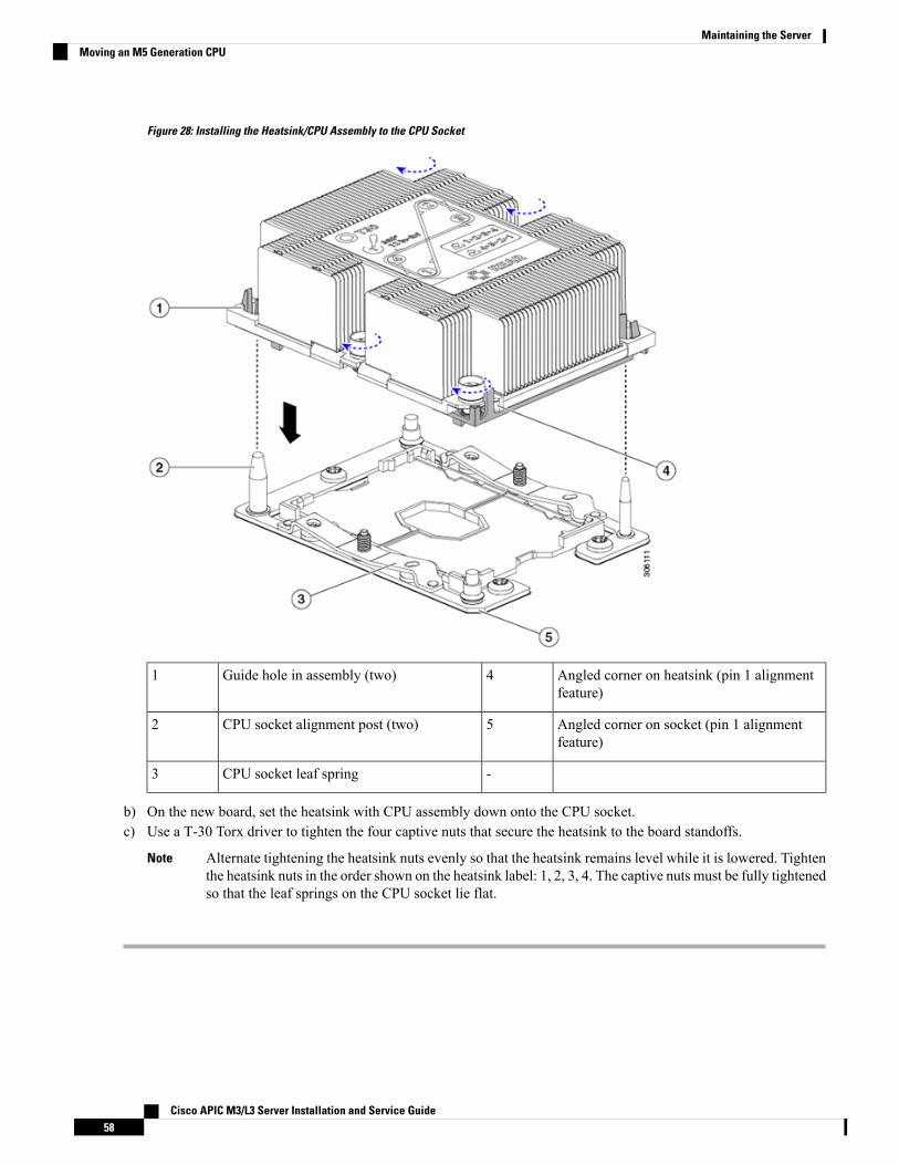
Figure 28: Installing the Heatsink/CPU Assembly to the CPU Socket
Angled corner on heatsink (pin 1 alignmentfeature)
4Guide hole in assembly (two)1
Angled corner on socket (pin 1 alignmentfeature)
5CPU socket alignment post (two)2
-CPU socket leaf spring3
b) On the new board, set the heatsink with CPU assembly down onto the CPU socket.c) Use a T-30 Torx driver to tighten the four captive nuts that secure the heatsink to the board standoffs.
Alternate tightening the heatsink nuts evenly so that the heatsink remains level while it is lowered. Tightenthe heatsink nuts in the order shown on the heatsink label: 1, 2, 3, 4. The captive nuts must be fully tightenedso that the leaf springs on the CPU socket lie flat.
Note
Cisco APIC M3/L3 Server Installation and Service Guide58
Maintaining the ServerMoving an M5 Generation CPU

Replacing a Mini-Storage ModuleThe mini-storage module plugs into a motherboard socket to provide additional internal storage. The moduleis available in two different versions:
• SD card carrier—provides two SD card sockets.
• M.2 SSD Carrier—provides twoM.2 form-factor SSD sockets. TheseM.2 SSDs can be either two SATASSDs or two NVMe SSDs (no mixing).
Replacing a Mini-Storage Module CarrierThis topic describes how to remove and replace a mini-storage module carrier. The carrier has one mediasocket on its top and one socket on its underside. Use the following procedure for any type of mini-storagemodule carrier (SD card or M.2 SSD).
Step 1 Shut down and remove power from the server as described in Shutting Down and Removing Power From the Server, onpage 29.
Step 2 Slide the server out the front of the rack far enough so that you can remove the top cover. You might have to detachcables from the rear panel to provide clearance.
If you cannot safely view and access the component, remove the server from the rack.Caution
Step 3 Remove the top cover from the server as described in Removing the Server Top Cover, on page 30.Step 4 Remove a carrier from its socket:
a) Locate the mini-storage module carrier in its socket just in front of power supply 1.b) At each end of the carrier, push outward on the clip that secures the carrier.c) Lift both ends of the carrier to disengage it from the socket on the motherboard.d) Set the carrier on an anti-static surface.
Step 5 Install a carrier to its socket:a) Position the carrier over socket, with the carrier's connector facing down and at the same end as the motherboard
socket. Two alignment pegs must match with two holes on the carrier.b) Gently push down the socket end of the carrier so that the two pegs go through the two holes on the carrier.c) Push down on the carrier so that the securing clips click over it at both ends.
Step 6 Replace the top cover to the server.Step 7 Replace the server in the rack, replace cables, and then fully power on the server by pressing the Power button.
Cisco APIC M3/L3 Server Installation and Service Guide59
Maintaining the ServerReplacing a Mini-Storage Module

Figure 29: Mini-Storage Module Carrier
Securing clips3Location of socket on motherboard1
-Alignment pegs2
Replacing an SD Card in a Mini-Storage Carrier For SDThis topic describes how to remove and replace an SD card in a mini-storage carrier for SD (PIDUCS-MSTOR-SD). The carrier has one SD card slot on its top and one slot on its underside.
Population Rules For Mini-Storage SD Cards
• You can use one or two SD cards in the carrier.
• Dual SD cards can be configured in a RAID 1 array through the Cisco IMC interface.
• SD slot 1 is on the top side of the carrier; SD slot 2 is on the underside of the carrier (the same side asthe carrier's motherboard connector).
Step 1 Power off the server and then remove the mini-storage module carrier from the server as described in Replacing aMini-Storage Module Carrier, on page 59.
Step 2 Remove an SD card:a) Push on the top of the SD card, and then release it to allow it to spring out from the socket.b) Grasp and remove the SD card from the socket.
Cisco APIC M3/L3 Server Installation and Service Guide60
Maintaining the ServerReplacing an SD Card in a Mini-Storage Carrier For SD

Step 3 Install a new SD card:a) Insert the new SD card into the socket with its label side facing up.b) Press on the top of the SD card until it clicks in the socket and stays in place.
Step 4 Install the mini-storage module carrier back into the server and then power it on as described in Replacing aMini-StorageModule Carrier, on page 59.
Replacing an M.2 SSD in a Mini-Storage Carrier For M.2This topic describes how to remove and replace an M.2 SATA or M.2 NVMe SSD in a mini-storage carrierfor M.2 (UCS-MSTOR-M2). The carrier has one M.2 SSD socket on its top and one socket on its underside.
Population Rules For Mini-Storage M.2 SSDs
• Both M.2 SSDs must be either SATA or NVMe; do not mix types in the carrier.
• You can use one or two M.2 SSDs in the carrier.
• M.2 socket 1 is on the top side of the carrier; M.2 socket 2 is on the underside of the carrier (the sameside as the carrier's motherboard connector).
• Dual SATA M.2 SSDs can be configured in a RAID 1 array with the BIOS Setup Utility's built inembedded SATA RAID utility.
If M.2 NVMe SSDs are installed in the M.2 module, the embedded SATA controller is automaticallydisabled.
You cannot control M.2 SATA SSDs in the server with a HW RAID controller.Note
Step 1 Power off the server and then remove the mini-storage module carrier from the server as described in Replacing aMini-Storage Module Carrier, on page 59.
Step 2 Remove an M.2 SSD:a) Use a #1 Phillips-head screwdriver to remove the single screw that secures the M.2 SSD to the carrier.b) Remove the M.2 SSD from its socket on the carrier.
Step 3 Install a new M.2 SSD:a) Angle the M.2 SSD downward and insert the connector-end into the socket on the carrier. The M.2 SSD's label must
face up.b) Press the M.2 SSD flat against the carrier.c) Install the single screw that secures the end of the M.2 SSD to the carrier.
Step 4 Install the mini-storage module carrier back into the server and then power it on as described in Replacing aMini-StorageModule Carrier, on page 59.
Replacing a Micro SD CardThere is one socket for a Micro SD card on the top of PCIe riser 1.
Cisco APIC M3/L3 Server Installation and Service Guide61
Maintaining the ServerReplacing an M.2 SSD in a Mini-Storage Carrier For M.2

To avoid data loss, we do not recommend that you hot-swap the Micro SD card while it is operating, asindicated by its activity LED turning amber. The activity LED turns amber when theMicro SD card is updatingor deleting.
Caution
Step 1 Remove an existing Micro SD card:a) Shut down and remove power from the server as described in Shutting Down and Removing Power From the Server,
on page 29.b) Slide the server out the front of the rack far enough so that you can remove the top cover. You might have to detach
cables from the rear panel to provide clearance.
If you cannot safely view and access the component, remove the server from the rack.Caution
c) Remove the top cover from the server as described in Removing the Server Top Cover, on page 30.d) Locate the Micro SD card. The socket is on the top of PCIe riser 1, under a flexible plastic cover.e) Use your fingertip to push open the retainer on the socket cover far enough to provide access to the Micro SD card,
then push down and release the Micro SD card to make it spring up.f) Grasp the Micro SD card and lift it from the socket.
Step 2 Install a new Micro SD card:a) While holding the retainer on the plastic cover open with your fingertip, align the newMicro SD card with the socket.b) Gently push down on the card until it clicks and locks in place in the socket.c) Replace the top cover to the server.d) Replace the server in the rack, replace cables, and then fully power on the server by pressing the Power button.
Figure 30: Internal Micro SD Card Socket
Plastic retainer (push aside to access socket)3Location of Micro SD card socket on the topof PCIe riser 1
1
Cisco APIC M3/L3 Server Installation and Service Guide62
Maintaining the ServerReplacing a Micro SD Card

Micro SD activity LED4Micro SD card socket under plastic retainer2
Replacing an Internal USB DriveThis section includes procedures for installing a USB drive and for enabling or disabling the internal USBport.
Replacing a USB Drive
We do not recommend that you hot-swap the internal USB drive while the server is powered on because ofthe potential for data loss.
Caution
Step 1 Remove an existing internal USB drive:a) Shut down and remove power from the server as described in Shutting Down and Removing Power From the Server,
on page 29.b) Slide the server out the front of the rack far enough so that you can remove the top cover. You might have to detach
cables from the rear panel to provide clearance.
If you cannot safely view and access the component, remove the server from the rack.Caution
c) Remove the top cover from the server as described in Removing the Server Top Cover, on page 30.d) Locate the USB socket on the motherboard, directly in front of PCIe riser 2.e) Grasp the USB drive and pull it horizontally to free it from the socket.
Step 2 Install a new internal USB drive:a) Align the USB drive with the socket.b) Push the USB drive horizontally to fully engage it with the socket.c) Replace the top cover to the server.d) Replace the server in the rack, replace cables, and then fully power on the server by pressing the Power button.
Cisco APIC M3/L3 Server Installation and Service Guide63
Maintaining the ServerReplacing an Internal USB Drive

Figure 31: Location of Internal USB Port
-Location of horizontal USB socket onmotherboard1
Enabling or Disabling the Internal USB PortThe factory default is that all USB ports on the server are enabled. However, the internal USB port can beenabled or disabled in the server BIOS.
Step 1 Enter the BIOS Setup Utility by pressing the F2 key when prompted during bootup.Step 2 Navigate to the Advanced tab.Step 3 On the Advanced tab, select USB Configuration.Step 4 On the USB Configuration page, select USB Ports Configuration.Step 5 Scroll to USB Port: Internal, press Enter, and then choose either Enabled or Disabled from the dialog box.Step 6 Press F10 to save and exit the utility.
Cisco APIC M3/L3 Server Installation and Service Guide64
Maintaining the ServerEnabling or Disabling the Internal USB Port

Replacing the RTC Battery
There is danger of explosion if the battery is replaced incorrectly. Replace the battery only with the same orequivalent type recommended by the manufacturer. Dispose of used batteries according to the manufacturer’sinstructions.
[Statement 1015]
Warning
The real-time clock (RTC) battery retains system settings when the server is disconnected from power. Thebattery type is CR2032. Cisco supports the industry-standard CR2032 battery, which can be ordered fromCisco (PID N20-MBLIBATT) or purchased from most electronic stores.
Step 1 Remove the RTC battery:a) Shut down and remove power from the server as described in Shutting Down and Removing Power From the Server,
on page 29.b) Slide the server out the front of the rack far enough so that you can remove the top cover. You might have to detach
cables from the rear panel to provide clearance.
If you cannot safely view and access the component, remove the server from the rack.Caution
c) Remove the top cover from the server as described in Removing the Server Top Cover, on page 30.d) Locate the RTC battery. The vertical socket is directly in front of PCIe riser 2.e) Remove the battery from the socket on the motherboard. Gently pry the securing clip on one side open to provide
clearance, then lift straight up on the battery.
Step 2 Install a new RTC battery:a) Insert the battery into its holder and press down until it clicks in place under the clip.
The flat, positive side of the battery marked “3V+” should face left as you face the server front.Note
b) Replace the top cover to the server.c) Replace the server in the rack, replace cables, and then fully power on the server by pressing the Power button.
Cisco APIC M3/L3 Server Installation and Service Guide65
Maintaining the ServerReplacing the RTC Battery

Figure 32: RTC Battery Location on Motherboard
-RTC battery in vertical socket1
Replacing Power SuppliesThe server can have one or two power supplies. When two power supplies are installed they are redundant as1+1.
This section includes procedures for replacing power supply units.
Replacing AC Power Supplies
If you have ordered a server with power supply redundancy (two power supplies), you do not have to poweroff the server to replace a power supply because they are redundant as 1+1.
Note
Do not mix power supply types or wattages in the server. Both power supplies must be identical.Note
Step 1 Remove the power supply that you are replacing or a blank panel from an empty bay:a) Perform one of the following actions:
Cisco APIC M3/L3 Server Installation and Service Guide66
Maintaining the ServerReplacing Power Supplies

• If your server has only one power supply, shut down and remove power from the server as described in ShuttingDown and Removing Power From the Server, on page 29.
• If your server has two power supplies, you do not have to shut down the server.
b) Remove the power cord from the power supply that you are replacing.c) Grasp the power supply handle while pinching the release lever toward the handle.d) Pull the power supply out of the bay.
Step 2 Install a new power supply:a) Grasp the power supply handle and insert the new power supply into the empty bay.b) Push the power supply into the bay until the release lever locks.c) Connect the power cord to the new power supply.d) Only if you shut down the server, press the Power button to boot the server to main power mode.
Figure 33: Replacing AC Power Supplies
Power supply handle2Power supply release lever1
Replacing a PCIe Card
Cisco supports all PCIe cards qualified and sold by Cisco. PCIe cards not qualified or sold by Cisco are theresponsibility of the customer. Although Cisco will always stand behind and support the C-Series rack-mountservers, customers using standard, off-the-shelf, third-party cards must go to the third-party card vendor forsupport if any issue with that particular card occurs.
Note
PCIe Slot SpecificationsThe server contains two PCIe slots on one riser assembly for horizontal installation of PCIe cards. Both slotssupport the NCSI protocol and 12V standby power.
Figure 34: Rear Panel, Showing PCIe Slot Numbering
Cisco APIC M3/L3 Server Installation and Service Guide67
Maintaining the ServerReplacing a PCIe Card

The following tables describe the specifications for the slots.
Table 6: PCIe Riser 1/Slot 1
NCSI SupportCard Height (Rear PanelOpening)
MaximumCard LengthConnector LengthElectrical Lane WidthSlot Number
YesFull-height¾ lengthx24 connectorGen-3 x161
One socket for Micro SD cardMicro SD cardslot
Table 7: PCIe Riser 2/Slot 2
NCSI SupportCard Height (RearPanel Opening)
Maximum CardLength
Connector LengthElectrical LaneWidth
Slot Number
Yes½ height½ lengthx24 connectorGen-3 x161
Other end of cable connects to front drive backplane to support front-panel NVMeSSDs.
Gen-3 x8PCIe cable connectorfor front-panel NVMeSSDs
Riser 1/Slot 1 is not available in single-CPU configurations.Note
Replacing a PCIe Card
If you are installing a Cisco Virtual Interface Card, there are prerequisite considerations. See Cisco VirtualInterface Card (VIC) Considerations, on page 70.
Note
RAID controller cards install into a separate mRAID riser. See Replacing a SAS Storage Controller Card(RAID or HBA), on page 74.
Note
Step 1 Remove an existing PCIe card (or a blank filler panel) from the PCIe riser:a) Shut down and remove power from the server as described in Shutting Down and Removing Power From the Server,
on page 29.b) Slide the server out the front of the rack far enough so that you can remove the top cover. You might have to detach
cables from the rear panel to provide clearance.
If you cannot safely view and access the component, remove the server from the rack.Caution
c) Remove the top cover from the server as described in Removing the Server Top Cover, on page 30.d) Remove any cables from the ports of the PCIe card that you are replacing.
Cisco APIC M3/L3 Server Installation and Service Guide68
Maintaining the ServerReplacing a PCIe Card

e) Use two hands to grasp the external riser handle and the blue area at the front of the riser.f) Lift straight up to disengage the riser's connectors from the two sockets on the motherboard. Set the riser upside-down
on an antistatic surface.g) Open the hinged plastic retainer that secures the rear-panel tab of the card.h) Pull evenly on both ends of the PCIe card to remove it from the socket on the PCIe riser.
If the riser has no card, remove the blanking panel from the rear opening of the riser.
Step 2 Install a new PCIe card:a) With the hinged tab retainer open, align the new PCIe card with the empty socket on the PCIe riser.
PCIe riser 1/slot 1 has a long-card guide at the front end of the riser. Use the slot in the long-card guide to help supporta full-length card.
b) Push down evenly on both ends of the card until it is fully seated in the socket.c) Ensure that the card’s rear panel tab sits flat against the riser rear-panel opening and then close the hinged tab retainer
over the card’s rear-panel tab.
Figure 35: PCIe Riser Assembly
Hinged card retainer (one each slot)4PCIe slot 1 rear-panel opening1
PCIe connector for cable that supportsfront-panel NVMe SSDs
5External riser handle2
Cisco APIC M3/L3 Server Installation and Service Guide69
Maintaining the ServerReplacing a PCIe Card

PCIe slot 2 rear-panel opening3
d) Position the PCIe riser over its two sockets on the motherboard and over the two chassis alignment channels.
Figure 36: PCIe Riser Alignment Features
Riser alignment features in chassis2Blue riser handle1
e) Carefully push down on both ends of the PCIe riser to fully engage its two connectors with the two sockets on themotherboard.
f) Replace the top cover to the server.g) Replace the server in the rack, replace cables, and then fully power on the server by pressing the Power button.
Cisco Virtual Interface Card (VIC) ConsiderationsThis section describes VIC card support and special considerations for this server.
If you use the Cisco Card NIC mode, you must also make a VIC Slot setting that matches where your VIC isinstalled. The options are Riser1, Riser2, and Flex-LOM. See NIC Mode and NIC Redundancy Settings, onpage 19 for more information about NIC modes.
Note
Table 8: VIC Support and Considerations in This Server
Minimum CiscoIMC Firmware
Primary Slot ForCisco Card NICMode
Primary Slot For CiscoUCS ManagerIntegration
Slots ThatSupport VICs
How ManySupported inServer
VIC
Cisco APIC M3/L3 Server Installation and Service Guide70
Maintaining the ServerCisco Virtual Interface Card (VIC) Considerations

4.0(1)PCIe 1PCIe 1PCIe 1
PCIe 2
2 PCIeCisco VIC 1455
APIC-PCIE-C25Q-04
This VIC supports 10/25-Gigabit with the following restrictions:
• All ports must have the same speed.
• Port-1 and port-2 is one pair, corresponding to eth2-1 on APIC. Port-3 and port-4 is another pair,corresponding to eth2-2 on APIC. Only one connection is allowed for each pair (For example, you canconnect one cable to either port-1 or port-2, and you can connect another one cable to either port-3 orport-4. Do not connect two cables on any pair.)
Note
Replacing an mLOM CardThe server supports a modular LOM (mLOM) card to provide additional rear-panel connectivity. The horizontalmLOM socket is on the motherboard, under the mRAID riser.
The mLOM socket provides a Gen-3 x16 PCIe lane. The socket remains powered when the server is in 12 Vstandby power mode and it supports the network communications services interface (NCSI) protocol.
Step 1 Remove any existing mLOM card (or a blanking panel):a) Shut down and remove power from the server as described in Shutting Down and Removing Power From the Server,
on page 29.b) Slide the server out the front of the rack far enough so that you can remove the top cover. You might have to detach
cables from the rear panel to provide clearance.
If you cannot safely view and access the component, remove the server from the rack.Caution
c) Remove the top cover from the server as described in Removing the Server Top Cover, on page 30.d) Remove the mRAID riser to provide access to the mLOM socket below the riser.
To remove the mRAID riser, use both hands to grasp the external blue handle on the rear and the blue finger-grip onthe front. Lift straight up.
You do not have to disconnect cables from any RAID card or interposer card that is installed in the riser. Carefullymove the riser aside only far enough to provide clearance.
e) Loosen the single captive thumbscrew that secures the mLOM card to the threaded standoff on the chassis floor.f) Slide the mLOM card horizontally to free it from the socket, then lift it out of the server.
Step 2 Install a new mLOM card:a) Set the mLOM card on the chassis floor so that its connector is aligned with the motherboard socket.b) Push the card horizontally to fully engage the card's edge connector with the socket.c) Tighten the captive thumbscrew to secure the card to the standoff on the chassis floor.d) Return the mRAID riser to its socket.
Cisco APIC M3/L3 Server Installation and Service Guide71
Maintaining the ServerReplacing an mLOM Card

Carefully align the riser's edge connector with the motherboard socket at the same time you align the two channelson the riser with the two pegs on the inner chassis wall. Press down evenly on both ends of the riser to fully engageits connector with the motherboard socket.
e) Replace the top cover to the server.f) Replace the server in the rack, replace cables, and then fully power on the server by pressing the Power button.
Figure 37: Location of the mLOM Card Socket Below the mRAID Riser
Position of mLOM card thumbscrew2Position of horizontal mLOM card socket1
Replacing an mRAID Riser (Riser 3)The server has a dedicated internal riser that is used for either a Cisco modular storage controller card (RAIDor HBA) or the SATA interposer card for embedded software RAID. This riser plugs into a dedicatedmotherboard socket and provides a horizontal socket for the installed card.
This riser can be ordered as the following options:
• UCSC-XRAIDR-220M5—Replacement unit for this mRAID riser.
• UCSC-MRAID1GB-KIT—Kit for first-time addition of this riser (includes RAID controller, supercap,and supercap cable).
See also Replacing a SAS Storage Controller Card (RAID or HBA), on page 74.
See also Replacing the Supercap (RAID Backup), on page 76.
• UCSC-SATA-KIT-M5—Kit for first-time addition of this riser (includes SATA interposer for embeddedsoftware RAID and SATA cables).
Cisco APIC M3/L3 Server Installation and Service Guide72
Maintaining the ServerReplacing an mRAID Riser (Riser 3)

See also Replacing a SATA Interposer Card , on page 78.
Step 1 Prepare the server for component installation:a) Shut down and remove power from the server as described in Shutting Down and Removing Power From the Server,
on page 29.b) Slide the server out the front of the rack far enough so that you can remove the top cover. You might have to detach
cables from the rear panel to provide clearance.
If you cannot safely view and access the component, remove the server from the rack.Caution
c) Remove the top cover from the server as described in Removing the Server Top Cover, on page 30.
Step 2 Remove the existing mRAID riser:a) Using both hands, grasp the external blue handle on the rear of the riser and the blue finger-grip on the front end of
the riser.b) Lift the riser straight up to disengage it from the motherboard socket.c) Set the riser upside down on an antistatic surface.d) Remove any card from the riser. Open the blue card-ejector lever that is on the edge of the card and then pull the card
straight out from its socket on the riser.
Step 3 Install a new mRAID riser:a) Install your card into the new riser. Close the card-ejector lever on the card to lock it into the riser.b) Connect cables to the installed card.
See Storage Controller and Backplane Connectors, on page 104 for cabling instructions for controller cards andinterposer cards.
c) Align the riser with the socket on the motherboard. At the same time, align the two slots on the back side of thebracket with the two pegs on the inner chassis wall.
d) Push down gently to engage the riser with the motherboard socket. The metal riser bracket must also engage the twopegs that secure it to the chassis wall.
Step 4 Replace the top cover to the server.Step 5 Replace the server in the rack, replace cables, and then fully power on the server by pressing the Power button.
Cisco APIC M3/L3 Server Installation and Service Guide73
Maintaining the ServerReplacing an mRAID Riser (Riser 3)

Figure 38: mRAID Riser (Internal Riser 3) Location
Card-ejector lever3External blue handle1
-Two pegs on inner chassis wall2
Replacing a SAS Storage Controller Card (RAID or HBA)For hardware-based storage control, the server can use a Cisco modular SAS RAID controller or SAS HBAthat plugs into a horizontal socket on a dedicated mRAID riser (internal riser 3).
You cannot use a hardware RAID controller card and the embedded software RAID controller to controlfront-panel drives at the same time.
Note
Storage Controller Card Firmware CompatibilityFirmware on the storage controller (RAID or HBA) must be verified for compatibility with the current CiscoIMC and BIOS versions that are installed on the server. If not compatible, upgrade or downgrade the storagecontroller firmware using the Host Upgrade Utility (HUU) for your firmware release to bring it to a compatiblelevel.
See the HUU guide for your Cisco IMC release for instructions on downloading and using the utility to bringserver components to compatible levels: HUU Guides.
Cisco APIC M3/L3 Server Installation and Service Guide74
Maintaining the ServerReplacing a SAS Storage Controller Card (RAID or HBA)

For servers running in standalone mode only: After you replace controller hardware (APIC-RAID-M5), youmust run the Cisco Host Upgrade Utility (HUU) to update the controller firmware, even if the firmware CurrentVersion is the same as the Update Version. This is necessary to program the controller's suboem-id to thecorrect value for the server SKU. If you do not do this, drive enumeration might not display correctly in thesoftware. This issue does not affect servers controlled in UCSM mode.
Note
Replacing a SAS Storage Controller Card (RAID or HBA)
Step 1 Prepare the server for component installation:a) Shut down and remove power from the server.b) Slide the server out the front of the rack far enough so that you can remove the top cover. You might have to detach
cables from the rear panel to provide clearance.
If you cannot safely view and access the component, remove the server from the rack.Caution
c) Remove the top cover from the server as described in Removing the Server Top Cover, on page 30.
Step 2 Remove the mRAID riser (riser 3) from the server:a) Using both hands, grasp the external blue handle on the rear of the riser and the blue finger-grip on the front end of
the riser.b) Lift the riser straight up to disengage it from the motherboard socket.c) Set the riser upside down on an antistatic surface.
Step 3 Remove any existing card from the riser:a) Disconnect cables from the existing card.b) Open the blue card-ejector lever on the back side of the card to eject it from the socket on the riser.c) Pull the card from the riser and set it aside.
Step 4 Install a new storage controller card to the riser:a) With the riser upside down, set the card on the riser.b) Push on both corners of the card to seat its connector in the riser socket.c) Close the card-ejector lever on the card to lock it into the riser.d) Connect cables to the installed card.
See Storage Controller and Backplane Connectors, on page 104 for cabling instructions for controller cards andinterposer cards.
Step 5 Return the riser to the server:a) Align the connector on the riser with the socket on the motherboard. At the same time, align the two slots on the back
side of the bracket with the two pegs on the inner chassis wall.b) Push down gently to engage the riser connector with the motherboard socket. The metal riser bracket must also engage
the two pegs that secure it to the chassis wall.
Step 6 Replace the top cover to the server.Step 7 Replace the server in the rack, replace cables, and then fully power on the server by pressing the Power button.
Step 8 If your server is running in standalone mode, use the Cisco Host Upgrade Utility to update the controller firmware andprogram the correct suboem-id for the controller.
Cisco APIC M3/L3 Server Installation and Service Guide75
Maintaining the ServerReplacing a SAS Storage Controller Card (RAID or HBA)

For servers running in standalone mode only: After you replace controller hardware (APIC-RAID-M5), youmust run the Cisco Host Upgrade Utility (HUU) to update the controller firmware, even if the firmware CurrentVersion is the same as the Update Version. This is necessary to program the controller's suboem-id to the correctvalue for the server SKU. If you do not do this, drive enumeration might not display correctly in the software.This issue does not affect servers controlled in UCSM mode.
See the HUU guide for your Cisco IMC release for instructions on downloading and using the utility to bringserver components to compatible levels: HUU Guides.
Note
Figure 39: mRAID Riser (Internal Riser 3) Location
Card-ejector lever3External blue handle1
-Two pegs on inner chassis wall2
Replacing the Supercap (RAID Backup)This server supports installation of one supercap unit. The unit mounts to a bracket that is in the middle ofthe row of cooling fan modules.
The supercap provides approximately three years of backup for the disk write-back cache DRAM in the caseof a sudden power loss by offloading the cache to the NAND flash.
Cisco APIC M3/L3 Server Installation and Service Guide76
Maintaining the ServerReplacing the Supercap (RAID Backup)

There is danger of explosion if the battery is replaced incorrectly. Replace the battery only with the same orequivalent type recommended by the manufacturer. Dispose of used batteries according to the manufacturer’sinstructions.
Statement 1015
Warning
Step 1 Prepare the server for component installation:a) Shut down and remove power from the server as described in Shutting Down and Removing Power From the Server,
on page 29.b) Slide the server out the front of the rack far enough so that you can remove the top cover. You might have to detach
cables from the rear panel to provide clearance.
If you cannot safely view and access the component, remove the server from the rack.Caution
c) Remove the top cover from the server as described in Removing the Server Top Cover, on page 30.
Step 2 Remove an existing supercap:a) Disconnect the supercap cable from the existing supercap.b) Push aside the securing tab to open the hinged latch that secures the supercap to its bracket on the removable air
baffle.c) Lift the supercap free of the bracket and set it aside.
Step 3 Install a new supercap:a) Set the new supercap into the mounting bracket.b) Close the hinged plastic clip over the supercap. Push down until the securing tab clicks.c) Connect the supercap cable from the RAID controller card to the connector on the new supercap cable.
Step 4 Replace the top cover to the server.Step 5 Replace the server in the rack, replace cables, and then fully power on the server by pressing the Power button.
Cisco APIC M3/L3 Server Installation and Service Guide77
Maintaining the ServerReplacing the Supercap (RAID Backup)

Figure 40: Replacing Supercap
Hinged latch2Securing tab1
Replacing a SATA Interposer CardFor software-based storage control that uses the server's embedded SATA controller, the server requires aSATA interposer card that plugs into a horizontal socket on a dedicated mRAID riser (internal riser 3).
You cannot use a hardware RAID controller card and the embedded software RAID controller at the sametime.
Note
Step 1 Prepare the server for component installation:
Cisco APIC M3/L3 Server Installation and Service Guide78
Maintaining the ServerReplacing a SATA Interposer Card

a) Shut down and remove power from the server as described in Shutting Down and Removing Power From the Server,on page 29.
b) Slide the server out the front of the rack far enough so that you can remove the top cover. You might have to detachcables from the rear panel to provide clearance.
If you cannot safely view and access the component, remove the server from the rack.Caution
c) Remove the top cover from the server as described in Removing the Server Top Cover, on page 30.
Step 2 Remove the mRAID riser (riser 3) from the server:a) Using both hands, grasp the external blue handle on the rear of the riser and the blue finger-grip on the front end of
the riser.b) Lift the riser straight up to disengage it from the motherboard socket.c) Set the riser upside down on an antistatic surface.
Step 3 Remove any existing card from the riser:a) Disconnect cables from the existing card.b) Open the blue card-ejector lever on the back side of the card to eject it from the socket on the riser.c) Pull the card from the riser and set it aside.
Step 4 Install a new card to the riser:a) With the riser upside down, set the card on the riser.b) Push on both corners of the card to seat its connector in the riser socket.c) Close the card-ejector lever on the card to lock it into the riser.
Step 5 Return the riser to the server:a) Align the connector on the riser with the socket on the motherboard. At the same time, align the two slots on the back
side of the bracket with the two pegs on the inner chassis wall.b) Push down gently to engage the riser connector with the motherboard socket. The metal riser bracket must also engage
the two pegs that secure it to the chassis wall.
Step 6 Reconnect the cables to their connectors on the new card.Step 7 Replace the top cover to the server.Step 8 Replace the server in the rack, replace cables, and then fully power on the server by pressing the Power button.
Cisco APIC M3/L3 Server Installation and Service Guide79
Maintaining the ServerReplacing a SATA Interposer Card

Figure 41: mRAID Riser (Internal Riser 3) Location
Card-ejector lever3External blue handle1
-Two pegs on inner chassis wall2
Replacing a Chassis Intrusion SwitchThe chassis intrusion switch in an optional security feature that logs an event in the system event log (SEL)whenever the cover is removed from the chassis.
Step 1 Prepare the server for component installation:a) Shut down and remove power from the server as described in Shutting Down and Removing Power From the Server,
on page 29.b) Slide the server out the front of the rack far enough so that you can remove the top cover. You might have to detach
cables from the rear panel to provide clearance.
If you cannot safely view and access the component, remove the server from the rack.Caution
c) Remove the top cover from the server as described in Removing the Server Top Cover, on page 30.
Step 2 Remove an existing intrusion switch:a) Disconnect the intrusion switch cable from the socket on the motherboard.b) Use a #1 Phillips-head screwdriver to loosen and remove the single screw that holds the switch mechanism to the
chassis wall.c) Slide the switch mechanism straight up to disengage it from the clips on the chassis.
Cisco APIC M3/L3 Server Installation and Service Guide80
Maintaining the ServerReplacing a Chassis Intrusion Switch

Step 3 Install a new intrusion switch:a) Slide the switch mechanism down into the clips on the chassis wall so that the screwhole lines up.b) Use a #1 Phillips-head screwdriver to install the single screw that secures the switch mechanism to the chassis wall.c) Connect the switch cable to the socket on the motherboard.
Step 4 Replace the cover to the server.Step 5 Replace the server in the rack, replace cables, and then fully power on the server by pressing the Power button.
Figure 42: Replacing a Chassis Intrusion Switch
-Intrusion switch location1
Installing a Trusted Platform Module (TPM)The trusted platform module (TPM) is a small circuit board that plugs into a motherboard socket and is thenpermanently secured with a one-way screw. The socket location is on the motherboard below PCIe riser 2.
TPM Considerations• This server supports either TPM version 1.2 or TPM version 2.0.
• Field replacement of a TPM is not supported; you can install a TPM after-factory only if the server doesnot already have a TPM installed.
• If there is an existing TPM 1.2 installed in the server, you cannot upgrade to TPM 2.0. If there is noexisting TPM in the server, you can install TPM 2.0.
Cisco APIC M3/L3 Server Installation and Service Guide81
Maintaining the ServerInstalling a Trusted Platform Module (TPM)

• If the TPM 2.0 becomes unresponsive, reboot the server.
Installing and Enabling a TPM
Field replacement of a TPM is not supported; you can install a TPM after-factory only if the server does notalready have a TPM installed.
Note
This topic contains the following procedures, whichmust be followed in this order when installing and enablinga TPM:
1. Installing the TPM Hardware
2. Enabling the TPM in the BIOS
3. Enabling the Intel TXT Feature in the BIOS
Installing TPM Hardware
For security purposes, the TPM is installed with a one-way screw. It cannot be removed with a standardscrewdriver.
Note
Step 1 Prepare the server for component installation:a) Shut down and remove power from the server as described in Shutting Down and Removing Power From the Server,
on page 29.b) Slide the server out the front of the rack far enough so that you can remove the top cover. You might have to detach
cables from the rear panel to provide clearance.
If you cannot safely view and access the component, remove the server from the rack.Caution
c) Remove the top cover from the server as described in Removing the Server Top Cover, on page 30.
Step 2 Check if there is a card installed in PCIe riser 2:
• If no card is installed in PCIe riser 2, you can access the TPM socket. Go to the next step.
• If a card is installed in PCIe riser 2, remove the PCIe riser assembly from the chassis to provide clearance beforecontinuing with the next step. See Replacing a PCIe Card, on page 68 for instructions on removing the PCIe riser.
Step 3 Install a TPM:a) Locate the TPM socket on the motherboard, as shown below.b) Align the connector that is on the bottom of the TPM circuit board with the motherboard TPM socket. Align the
screw hole on the TPM board with the screw hole that is adjacent to the TPM socket.c) Push down evenly on the TPM to seat it in the motherboard socket.d) Install the single one-way screw that secures the TPM to the motherboard.e) If you removed the PCIe riser assembly to provide clearance, return it to the server now.
Step 4 Replace the cover to the server.
Cisco APIC M3/L3 Server Installation and Service Guide82
Maintaining the ServerInstalling and Enabling a TPM

Step 5 Replace the server in the rack, replace cables, and then fully power on the server by pressing the Power button.
Figure 43: Location of the TPM Socket
-TPM socket location on motherboard belowany card in PCIe riser 2
1
Step 6 Continue with Enabling the TPM in the BIOS, on page 83.
Enabling the TPM in the BIOS
After hardware installation, you must enable TPM support in the BIOS.
You must set a BIOS Administrator password before performing this procedure. To set this password, pressthe F2 key when prompted during system boot to enter the BIOS Setup utility. Then navigate to Security >Set Administrator Password and enter the new password twice as prompted.
Note
Step 1 Enable TPM Support:a) Watch during bootup for the F2 prompt, and then press F2 to enter BIOS setup.b) Log in to the BIOS Setup Utility with your BIOS Administrator password.c) On the BIOS Setup Utility window, choose the Advanced tab.d) Choose Trusted Computing to open the TPM Security Device Configuration window.e) Change TPM SUPPORT to Enabled.f) Press F10 to save your settings and reboot the server.
Step 2 Verify that TPM support is now enabled:a) Watch during bootup for the F2 prompt, and then press F2 to enter BIOS setup.
Cisco APIC M3/L3 Server Installation and Service Guide83
Maintaining the ServerEnabling the TPM in the BIOS

b) Log into the BIOS Setup utility with your BIOS Administrator password.c) Choose the Advanced tab.d) Choose Trusted Computing to open the TPM Security Device Configuration window.e) Verify that TPM SUPPORT and TPM State are Enabled.
Step 3 Continue with Enabling the Intel TXT Feature in the BIOS, on page 84.
Enabling the Intel TXT Feature in the BIOS
Intel Trusted Execution Technology (TXT) provides greater protection for information that is used and storedon the business server. A key aspect of that protection is the provision of an isolated execution environmentand associated sections of memory where operations can be conducted on sensitive data, invisibly to the restof the system. Intel TXT provides for a sealed portion of storage where sensitive data such as encryption keyscan be kept, helping to shield them from being compromised during an attack by malicious code.
Step 1 Reboot the server and watch for the prompt to press F2.Step 2 When prompted, press F2 to enter the BIOS Setup utility.Step 3 Verify that the prerequisite BIOS values are enabled:
a) Choose the Advanced tab.b) Choose Intel TXT(LT-SX) Configuration to open the Intel TXT(LT-SX) Hardware Support window.c) Verify that the following items are listed as Enabled:
• VT-d Support (default is Enabled)
• VT Support (default is Enabled)
• TPM Support
• TPM State
d) Do one of the following:
• If VT-d Support and VT Support are already enabled, skip to step 4.
• If VT-d Support and VT Support are not enabled, continue with the next steps to enable them.
e) Press Escape to return to the BIOS Setup utility Advanced tab.f) On the Advanced tab, choose Processor Configuration to open the Processor Configuration window.g) Set Intel (R) VT and Intel (R) VT-d to Enabled.
Step 4 Enable the Intel Trusted Execution Technology (TXT) feature:a) Return to the Intel TXT(LT-SX) Hardware Support window if you are not already there.b) Set TXT Support to Enabled.
Step 5 Press F10 to save your changes and exit the BIOS Setup utility.
Cisco APIC M3/L3 Server Installation and Service Guide84
Maintaining the ServerEnabling the Intel TXT Feature in the BIOS

Service Headers and JumpersThis server includes two blocks of headers (J38, J39) that you can jumper for certain service and debugfunctions.
Figure 44: Location of Service Header Blocks J38 and J39
Location of header block J396Location of header block J381
J39 pin 1 arrow printed on motherboard7J38 pin 1 arrow printed on motherboard2
Boot Cisco IMC from alternate image: J39 pins 1 -2
8Clear CMOS: J38 pins 9 - 103
Reset Cisco IMC password to default: J39 pins 3 -4
9Recover BIOS: J38 pins 11 - 124
Reset Cisco IMC to defaults: J39 pins 5 - 610Clear password: J38 pins 13 - 145
Cisco APIC M3/L3 Server Installation and Service Guide85
Maintaining the ServerService Headers and Jumpers

Using the Clear CMOS Header (J38, Pins 9 - 10)You can use this header to clear the server’s CMOS settings in the case of a system hang. For example, if theserver hangs because of incorrect settings and does not boot, use this jumper to invalidate the settings andreboot with defaults.
Clearing the CMOS removes any customized settings and might result in data loss. Make a note of anynecessary customized settings in the BIOS before you use this clear CMOS procedure.
Caution
Step 1 Shut down and remove power from the server as described in Shutting Down and Removing Power From the Server,on page 29. Disconnect power cords from all power supplies.
Step 2 Slide the server out the front of the rack far enough so that you can remove the top cover. You might have to detachcables from the rear panel to provide clearance.
If you cannot safely view and access the component, remove the server from the rack.Caution
Step 3 Remove the top cover from the server as described in Removing the Server Top Cover, on page 30.Step 4 Locate header block J38 and pins 9-10, as shown in Service Headers and Jumpers, on page 85.Step 5 Install a two-pin jumper across pins 9 and 10.Step 6 Reinstall the top cover and reconnect AC power cords to the server. The server powers up to standby power mode,
indicated when the Power LED on the front panel is amber.Step 7 Return the server to main power mode by pressing the Power button on the front panel. The server is in main power
mode when the Power LED is green.
You must allow the entire server to reboot to main power mode to complete the reset. The state of the jumpercannot be determined without the host CPU running.
Note
Step 8 Press the Power button to shut down the server to standby power mode, and then remove AC power cords from theserver to remove all power.
Step 9 Remove the top cover from the server.Step 10 Remove the jumper that you installed.
If you do not remove the jumper, the CMOS settings are reset to the defaults every time you power-cycle theserver.
Note
Step 11 Replace the top cover, replace the server in the rack, replace power cords and any other cables, and then power on theserver by pressing the Power button.
Using the BIOS Recovery Header (J38, Pins 11 - 12)Depending on which stage the BIOS becomes corrupted, you might see different behavior.
• If the BIOS BootBlock is corrupted, you might see the system get stuck on the following message:Initializing and configuring memory/hardware
• If it is a non-BootBlock corruption, a message similar to the following is displayed:
Cisco APIC M3/L3 Server Installation and Service Guide86
Maintaining the ServerUsing the Clear CMOS Header (J38, Pins 9 - 10)

****BIOS FLASH IMAGE CORRUPTED****Flash a valid BIOS capsule file using Cisco IMC WebGUI or CLI interface.IF Cisco IMC INTERFACE IS NOT AVAILABLE, FOLLOW THE STEPS MENTIONED BELOW.1. Connect the USB stick with bios.cap file in root folder.2. Reset the host.IF THESE STEPS DO NOT RECOVER THE BIOS1. Power off the system.2. Mount recovery jumper.3. Connect the USB stick with bios.cap file in root folder.4. Power on the system.Wait for a few seconds if already plugged in the USB stick.REFER TO SYSTEM MANUAL FOR ANY ISSUES.
As indicated by the message shown above, there are two procedures for recovering the BIOS. Try procedure1 first. If that procedure does not recover the BIOS, use procedure 2.
Note
Procedure 1: Reboot With recovery.cap File
Step 1 Download the BIOS update package and extract it to a temporary location.Step 2 Copy the contents of the extracted recovery folder to the root directory of a USB drive. The recovery folder contains the
bios.cap file that is required in this procedure.
The bios.cap file must be in the root directory of the USB drive. Do not rename this file. The USB drive mustbe formatted with either the FAT16 or FAT32 file system.
Note
Step 3 Insert the USB drive into a USB port on the server.Step 4 Reboot the server.Step 5 Return the server to main power mode by pressing the Power button on the front panel.
The server boots with the updated BIOS boot block. When the BIOS detects a valid bios.cap file on the USB drive, itdisplays this message:Found a valid recovery file...Transferring to Cisco IMCSystem would flash the BIOS image now...System would restart with recovered image after a few seconds...
Step 6 Wait for server to complete the BIOS update, and then remove the USB drive from the server.
During the BIOS update, Cisco IMC shuts down the server and the screen goes blank for about 10 minutes.Do not unplug the power cords during this update. Cisco IMC powers on the server after the update is complete.
Note
Procedure 2: Use BIOS Recovery Header and bios.cap Recovery File
Step 1 Download the BIOS update package and extract it to a temporary location.Step 2 Copy the contents of the extracted recovery folder to the root directory of a USB drive. The recovery folder contains
the bios.cap file that is required in this procedure.
The bios.cap file must be in the root directory of the USB drive. Do not rename this file. The USB drive mustbe formatted with either the FAT16 or FAT32 file system.
Note
Cisco APIC M3/L3 Server Installation and Service Guide87
Maintaining the ServerProcedure 1: Reboot With recovery.cap File

Step 3 Shut down and remove power from the server as described in Shutting Down and Removing Power From the Server,on page 29. Disconnect power cords from all power supplies.
Step 4 Slide the server out the front of the rack far enough so that you can remove the top cover. You might have to detachcables from the rear panel to provide clearance.
If you cannot safely view and access the component, remove the server from the rack.Caution
Step 5 Remove the top cover from the server as described in Removing the Server Top Cover, on page 30.Step 6 Locate header block J38 and pins 11-12, as shown in Service Headers and Jumpers, on page 85.Step 7 Install a two-pin jumper across pins 11 and 12.Step 8 Reconnect AC power cords to the server. The server powers up to standby power mode.Step 9 Insert the USB thumb drive that you prepared in Step 2 into a USB port on the server.Step 10 Return the server to main power mode by pressing the Power button on the front panel.
The server boots with the updated BIOS boot block. When the BIOS detects a valid bios.cap file on the USB drive, itdisplays this message:Found a valid recovery file...Transferring to Cisco IMCSystem would flash the BIOS image now...System would restart with recovered image after a few seconds...
Step 11 Wait for server to complete the BIOS update, and then remove the USB drive from the server.
During the BIOS update, Cisco IMC shuts down the server and the screen goes blank for about 10 minutes.Do not unplug the power cords during this update. Cisco IMC powers on the server after the update is complete.
Note
Step 12 After the server has fully booted, power off the server again and disconnect all power cords.Step 13 Remove the jumper that you installed.
If you do not remove the jumper, after recovery completion you see the prompt, “Please remove the recoveryjumper.”
Note
Step 14 Replace the top cover, replace the server in the rack, replace power cords and any other cables, and then power on theserver by pressing the Power button.
Using the Clear Password Header (J38, Pins 13 - 14)You can use this switch to clear the administrator password.
Step 1 Shut down and remove power from the server as described in Shutting Down and Removing Power From the Server,on page 29. Disconnect power dords from all power supplies.
Step 2 Slide the server out the front of the rack far enough so that you can remove the top cover. You might have to detachcables from the rear panel to provide clearance.
If you cannot safely view and access the component, remove the server from the rack.Caution
Step 3 Remove the top cover from the server as described in Removing the Server Top Cover, on page 30.Step 4 Install a two-pin jumper across J38 pins 13 and 14.Step 5 Reinstall the top cover and reconnect AC power cords to the server. The server powers up to standby power mode,
indicated when the Power LED on the front panel is amber.
Cisco APIC M3/L3 Server Installation and Service Guide88
Maintaining the ServerUsing the Clear Password Header (J38, Pins 13 - 14)

Step 6 Return the server to main power mode by pressing the Power button on the front panel. The server is in main powermode when the Power LED is green.
You must allow the entire server to reboot to main power mode to complete the reset. The state of the jumpercannot be determined without the host CPU running.
Note
Step 7 Press the Power button to shut down the server to standby power mode, and then remove AC power cords from theserver to remove all power.
Step 8 Remove the top cover from the server.Step 9 Remove the jumper that you installed.
If you do not remove the jumper, the password is cleared every time you power-cycle the server.Note
Step 10 Replace the top cover, replace the server in the rack, replace power cords and any other cables, and then power on theserver by pressing the Power button.
Using the Boot Alternate Cisco IMC Image Header (J39, Pins 1 - 2)You can use this Cisco IMC debug header to force the system to boot from an alternate Cisco IMC image.
Step 1 Shut down and remove power from the server as described in Shutting Down and Removing Power From the Server.Disconnect power cords from all power supplies.
Step 2 Slide the server out the front of the rack far enough so that you can remove the top cover. You might have to detachcables from the rear panel to provide clearance.
If you cannot safely view and access the component, remove the server from the rack.Caution
Step 3 Remove the top cover from the server as described in Removing the Server Top Cover.Step 4 Locate header block J39, pins 1-2, as shown in Service Headers and Jumpers.Step 5 Install a two-pin jumper across J39 pins 1 and 2.Step 6 Reinstall the top cover and reconnect AC power cords to the server. The server powers up to standby power mode,
indicated when the Power LED on the front panel is amber.Step 7 Return the server to main power mode by pressing the Power button on the front panel. The server is in main power
mode when the Power LED is green.
When you next log in to Cisco IMC, you see a message similar to the following:'Boot from alternate image' debug functionality is enabled.CIMC will boot from alternate image on next reboot or input power cycle.
Note
Step 8 Press the Power button to shut down the server to standby power mode, and then remove AC power cords from theserver to remove all power.
Step 9 Remove the top cover from the server.Step 10 Remove the jumper that you installed.
If you do not remove the jumper, the server will boot from an alternate Cisco IMC image every time that youpower cycle the server or reboot Cisco IMC.
Note
Cisco APIC M3/L3 Server Installation and Service Guide89
Maintaining the ServerUsing the Boot Alternate Cisco IMC Image Header (J39, Pins 1 - 2)

Step 11 Replace the top cover, replace the server in the rack, replace power cords and any other cables, and then power on theserver by pressing the Power button.
Using the Reset Cisco IMC Password to Default Header (J39, Pins 3 - 4)You can use this Cisco IMC debug header to force the Cisco IMC password back to the default.
Step 1 Shut down and remove power from the server as described in Shutting Down and Removing Power From the Server,on page 29. Disconnect power cords from all power supplies.
Step 2 Slide the server out the front of the rack far enough so that you can remove the top cover. You might have to detachcables from the rear panel to provide clearance.
If you cannot safely view and access the component, remove the server from the rack.Caution
Step 3 Remove the top cover from the server as described in Removing the Server Top Cover, on page 30.Step 4 Locate header block J39, pins 3-4, as shown in Service Headers and Jumpers, on page 85.Step 5 Install a two-pin jumper across J39 pins 3 and 4.Step 6 Reinstall the top cover and reconnect AC power cords to the server. The server powers up to standby power mode,
indicated when the Power LED on the front panel is amber.Step 7 Return the server to main power mode by pressing the Power button on the front panel. The server is in main power
mode when the Power LED is green.
When you next log in to Cisco IMC, you see a message similar to the following:'Reset to default CIMC password' debug functionality is enabled.On input power cycle, CIMC password will be reset to defaults.
Note
Step 8 Press the Power button to shut down the server to standby power mode, and then remove AC power cords from theserver to remove all power.
Step 9 Remove the top cover from the server.Step 10 Remove the jumper that you installed.
If you do not remove the jumper, the server will reset the Cisco IMC password to the default every time thatyou power cycle the server. The jumper has no effect if you reboot Cisco IMC.
Note
Step 11 Replace the top cover, replace the server in the rack, replace power cords and any other cables, and then power on theserver by pressing the Power button.
Using the Reset Cisco IMC to Defaults Header (J39, Pins 5 - 6)You can use this Cisco IMC debug header to force the Cisco IMC settings back to the defaults.
Step 1 Shut down and remove power from the server as described in Shutting Down and Removing Power From the Server,on page 29. Disconnect power cords from all power supplies.
Step 2 Slide the server out the front of the rack far enough so that you can remove the top cover. You might have to detachcables from the rear panel to provide clearance.
Cisco APIC M3/L3 Server Installation and Service Guide90
Maintaining the ServerUsing the Reset Cisco IMC Password to Default Header (J39, Pins 3 - 4)

If you cannot safely view and access the component, remove the server from the rack.Caution
Step 3 Remove the top cover from the server as described in Removing the Server Top Cover, on page 30.Step 4 Locate header block J39, pins 5-6, as shown in Service Headers and Jumpers, on page 85.Step 5 Install a two-pin jumper across J39 pins 5 and 6.Step 6 Reinstall the top cover and reconnect AC power cords to the server. The server powers up to standby power mode,
indicated when the Power LED on the front panel is amber.Step 7 Return the server to main power mode by pressing the Power button on the front panel. The server is in main power
mode when the Power LED is green.
When you next log in to Cisco IMC, you see a message similar to the following:'CIMC reset to factory defaults' debug functionality is enabled.On input power cycle, CIMC will be reset to factory defaults.
Note
Step 8 To remove the jumper, press the Power button to shut down the server to standby power mode, and then remove ACpower cords from the server to remove all power.
Step 9 Remove the top cover from the server.Step 10 Remove the jumper that you installed.
If you do not remove the jumper, the server will reset the Cisco IMC to the default settiings every time thatyou power cycle the server. The jumper has no effect if you reboot Cisco IMC.
Note
Step 11 Replace the top cover, replace the server in the rack, replace power cords and any other cables, and then power on theserver by pressing the Power button.
Cisco APIC M3/L3 Server Installation and Service Guide91
Maintaining the ServerUsing the Reset Cisco IMC to Defaults Header (J39, Pins 5 - 6)

Cisco APIC M3/L3 Server Installation and Service Guide92
Maintaining the ServerUsing the Reset Cisco IMC to Defaults Header (J39, Pins 5 - 6)

A P P E N D I X AServer Specifications
• Server Specifications, on page 93
Server SpecificationsThis appendix lists the physical, environmental, and power specifications for the server.
• Physical Specifications, on page 93
• Environmental Specifications, on page 93
• Power Specifications, on page 95
Physical SpecificationsThe following table lists the physical specifications for the server versions.
Table 9: Physical Specifications
SpecificationDescription
1.7 in. (43.2 mm)Height
16.9 in. (429.0 mm)Width
Server only: 29.5 in. (740.3 mm)
Server with slide rail: 31.0 in (787.4 mm)
Depth(length)
Maximum: 37.5 lb. (17.0 Kg)
Minimum: 29.0 lb. (13.2 Kg)
Weight
Environmental SpecificationsThe following table lists the environmental requirements and specifications for the server.
Cisco APIC M3/L3 Server Installation and Service Guide93

Table 10: Physical Specifications
SpecificationDescription
41 to 95°F (5 to 35°C)
Derate the maximum temperature by 1°C per every 305 meters of altitude abovesea level.
Temperature, Operating
–40 to 149°F (–40 to 65°C)Temperature, non-operating
(when the server is stored or transported)
10 to 90%Humidity (RH), operating
5 to 93%Humidity (RH), non-operating
(when the server is stored or transported)
0 to 10,000 feetAltitude, operating
0 to 40,000 feetAltitude, non-operating
(when the server is stored or transported)
5.5Sound power level
Measure A-weighted per ISO7779 LwAd (Bels)
Operation at 73°F (23°C)
40Sound pressure level
Measure A-weighted per ISO7779 LpAm (dBA)
Operation at 73°F (23°C)
Cisco Virtual Interface Card (VIC) ConsiderationsThis section describes VIC card support and special considerations for this server.
If you use the Cisco Card NIC mode, you must also make a VIC Slot setting that matches where your VIC isinstalled. The options are Riser1, Riser2, and Flex-LOM. See NIC Mode and NIC Redundancy Settings, onpage 19 for more information about NIC modes.
Note
Table 11: VIC Support and Considerations in This Server
Minimum CiscoIMC Firmware
Primary Slot ForCisco Card NICMode
Primary Slot For CiscoUCS ManagerIntegration
Slots ThatSupport VICs
How ManySupported inServer
VIC
4.0(1)PCIe 1PCIe 1PCIe 1
PCIe 2
2 PCIeCisco VIC 1455
APIC-PCIE-C25Q-04
Cisco APIC M3/L3 Server Installation and Service Guide94
Server SpecificationsCisco Virtual Interface Card (VIC) Considerations

This VIC supports 10/25-Gigabit with the following restrictions:
• All ports must have the same speed.
• Port-1 and port-2 is one pair, corresponding to eth2-1 on APIC. Port-3 and port-4 is another pair,corresponding to eth2-2 on APIC. Only one connection is allowed for each pair (For example, you canconnect one cable to either port-1 or port-2, and you can connect another one cable to either port-3 orport-4. Do not connect two cables on any pair.)
Note
Power SpecificationsTable 12: M3 System Load Estimates
100%75%50%System Workload Factor
409.91 W409.91 W409.91 WMaximum Input Power
409.91 W338.59 W268.24 WInput Power
129.18 W129.18 W129.18 WIdle Input Power
1.72 A1.43 A1.13 AInput Current
48.43 cfm40 cfm31.69 cfmAir Flow
1398.68 BTU/hr.1155.31 BTU/hr.915.28 BTU/hr.Cooling
Table 13: L3 System Load Estimates
100%75%50%System Workload Factor
429.85 W429.85 W429.85 WMaximum Input Power
429.85 W355 W280.83 WInput Power
134.26 W134.26 W134.26 WIdle Input Power
1.81 A1.5 A1.19 AInput Current
50.78 cfm41.94 cfm33.18 cfmAir Flow
1466.71 BTU/hr.1211.31 BTU/hr.958.22 BTU/hr.Cooling
Do not mix power supply types or wattages in the server. Both power supplies must be identical.Note
You can get more specific power information for your exact server configuration by using the Cisco UCSPower Calculator:
Cisco APIC M3/L3 Server Installation and Service Guide95
Server SpecificationsPower Specifications

http://ucspowercalc.cisco.com
The power specifications for the supported power supply options are listed in the following sections.
770 W AC Power SupplyThis section lists the specifications for each 770WAC power supply (Cisco part number APIC-PSU1-770W).
Table 14: 770 W AC Specifications
SpecificationDescription
Nominal range: 100–120 VAC, 200–240 VAC
(Range: 90–132 VAC, 180–264 VAC)
AC Input Voltage
Nominal range: 50 to 60Hz
(Range: 47–63 Hz)
AC Input Frequency
9.5 A at 100 VAC
4.5 A at 208 VAC
Maximum AC Input current
950 VA at 100 VACMaximum input volt-amperes
15 A (sub-cycle duration)Maximum inrush current
12 ms at 770 WMaximum hold-up time
770 WMaximumoutput power per PSU
12 VDCPower supply output voltage
12 VDCPower supply standby voltage
Climate Savers Platinum Efficiency (80Plus Platinum certified)Efficiency rating
RSP2Form factor
IEC320 C14Input connector
1050 W DC Power SupplyThis section lists the specifications for each 1050 W DC power supply (Cisco part numberUCSC-PSUV2-1050DC).
Table 15: 1050 W DC Specifications
SpecificationDescription
Nominal range: -48 to -60 VDC
(Range: -40 to -72 VDC)
DC Input Voltage
32 A at -40 VDCMaximum DC input current
Cisco APIC M3/L3 Server Installation and Service Guide96
Server Specifications770 W AC Power Supply

1234 WMaximum input wattage
35 A (sub-cycle duration)Maximum inrush current
5 ms at 100% load (1050Wmain and 36W standby)Maximum hold-up time
1050 W on 12 VDC main power
36 W on 12 VDC standby power
Maximumoutput power per PSU
12 VDCPower supply output voltage
12 VDCPower supply standby voltage
≥ 92% at 50% loadEfficiency rating
RSP2Form factor
Fixed 3-wire blockInput connector
Power Cord SpecificationsEach power supply in the server has a power cord. Standard power cords or jumper power cords are availablefor connection to the server. The shorter jumper power cords, for use in racks, are available as an optionalalternative to the standard power cords.
Only the approved power cords or jumper power cords listed below are supported.Note
Table 16: Supported Power Cords
Length (Meters)Length (Feet)Description
3.511.7CAB-48DC-40A-8AWG
DC power cord, -48 VDC, 40 A, 8 AWG
Three-socket Mini-Fit connector to three-wire
3.09.8CAB-C13-C14-AC
AC power cord, 10 A; C13 to C14, recessed receptacle
2.58.2CAB-250V-10A-AR
AC power cord, 250 V, 10 A
Argentina
2.06.6CAB-C13-C14-2M-JP
AC Power Cord, C13 to C14
Japan PSE Mark
Cisco APIC M3/L3 Server Installation and Service Guide97
Server SpecificationsPower Cord Specifications

2.58.2CAB-9K10A-EU
AC Power Cord, 250 V, 10 A; CEE 7/7 Plug
Europe
2.58.2CAB-250V-10A-IS
AC Power Cord, 250 V, 10 A
Israel
2.58.2CAB-250V-10A-CN
AC power cord, 250 V, 10 A
PR China
2.37.5CAB-ACTW
AC power cord, 250 V, 10 A
Taiwan
0.682.2CAB-C13-CBN
AC cabinet jumper power cord, 250, 10 A,
C13 to C14
2.06.6CAB-C13-C14-2M
AC cabinet jumper power cord, 250 V, 10 A,
C13 to C14
2.58.2CAB-9K10A-AU
AC power cord, 250 V, 10 A, 3112 plug,
Australia
2.58.2CAB-N5K6A-NA
AC power cord, 200/240 V, 6 A,
North America
2.58.2CAB-250V-10A-ID
AC power Cord, 250 V, 10 A,
India
2.58.2CAB-9K10A-SW
AC power cord, 250 V, 10 A, MP232 plug
Switzerland
Cisco APIC M3/L3 Server Installation and Service Guide98
Server SpecificationsServer Specifications

2.58.2CAB-250V-10A-BR
AC power Cord, 250 V, 10 A
Brazil
2.58.2CAB-9K10A-UK
AC power cord, 250 V, 10 A (13 A fuse), BS1363 plug
United Kingdom
2.58.2CAB-9K12A-NA
AC power cord, 125 V, 13 A, NEMA 5-15 plug
North America
2.06.6CAB-AC-L620-C13
AC power cord, NEMA L6-20 to C13 connectors
2.58.2CAB-9K10A-IT
AC power cord, 250 V, 10 A, CEI 23-16/VII plug
Italy
NANAR2XX-DMYMPWRCORD
No power cord; PID option for ordering server with no power cord
Cisco APIC M3/L3 Server Installation and Service Guide99
Server SpecificationsServer Specifications

Cisco APIC M3/L3 Server Installation and Service Guide100
Server SpecificationsServer Specifications

A P P E N D I X BStorage Controller Considerations
This appendix provides storage controller (RAID and HBA) information.
• Supported Storage Controllers and Cables, on page 101• Storage Controller Card Firmware Compatibility, on page 102• Write-Cache Policy for Cisco 12G SAS Modular RAID Controller, on page 103• Mixing Drive Types in RAID Groups, on page 103• RAID Controller Migration, on page 104• Storage Controller and Backplane Connectors, on page 104• Embedded SATA RAID Controller, on page 106• For More RAID Utility Information, on page 115
Supported Storage Controllers and CablesThis server supports a single, PCIe-style, SAS RAID or HBA controller that plugs into a dedicated internalriser. Alternatively, the server has a software-based SATA RAID controller embedded in the system.
Do not mix controller types in the server. Do not use the embedded SATA controller and a hardware-basedRAID controller card at the same time. This combination is not supported and could result in data loss.
Note
NVMe PCIe SSDs cannot be controlled by a SAS/SATA RAID controller.Note
This server supports the RAID and HBA controller options and cable requirements shown in the followingtable.
Required CablesOptionalSupercapBackup?
RAIDLevelsServer Version/Maximum DrivesControlled
Controller
Cisco APIC M3/L3 Server Installation and Service Guide101

Use SAS/SATA cable includedwith chassis to connect interposerboard to drive backplane.
No0, 1, 10This controller is supported only in theseserver versions:
• All server versions can use theembedded SATA controller to controltwo internal SATA M.2 drives.
• SFF 10-drives (C220M5SX):
8 front-loading SATA drives (drivebays 1 - 8)
• LFF 4-drives (C220M5L):
4 front-loading SATA drives
Embedded RAID (PCHSATA)
Use SAS/SATA cable includedwith chassis to connect controllerto drive backplane.
Yes0, 1, 5, 6, 10,50, 60
This controller is supported only in thisserver version:
• LFF 4-drives (C220M5L):
4 front-loading SAS/SATA drives
Cisco 12G Modular RAIDController
Controller is orderable onlyas UCSC-MRAID1G-KIT
Use SAS/SATA cable includedwith chassis to connect controllerto drive backplane.
Yes0, 1, 5, 6, 10,50, 60
This controller is supported only in theseserver versions:
• SFF 10-drives (C220M5SX):
10 front-loading SAS/SATA drives
Cisco 12G Modular RAIDController with 2-GB cache
APIC-RAID-M5
Includes 2-GB cache
Use SAS/SATA cable includedwith chassis to connect controllerto drive backplane.
NoNon-RAIDThis controller is supported only in theseserver versions:
• SFF 10-drives (C220M5SX):
10 front-loading SAS/SATA drives
Cisco 12G Modular SASHBA
UCSC-SAS-M5
External drive cables not sold byCisco.
NOTE: This HBA does notsupport optical cables forconnection to external storage(copper only).
NoNon-RAIDSupported in all server versions:
8 external SAS/SATA ports, controllingup to 1024 external drives.
Cisco 12G 9400-8e HBAfor external JBOD attach
UCSC-9400-8E
Storage Controller Card Firmware CompatibilityFirmware on the storage controller (RAID or HBA) must be verified for compatibility with the current CiscoIMC and BIOS versions that are installed on the server. If not compatible, upgrade or downgrade the storagecontroller firmware using the Host Upgrade Utility (HUU) for your firmware release to bring it to a compatiblelevel.
See the HUU guide for your Cisco IMC release for instructions on downloading and using the utility to bringserver components to compatible levels: HUU Guides.
Cisco APIC M3/L3 Server Installation and Service Guide102
Storage Controller ConsiderationsStorage Controller Card Firmware Compatibility
For servers running in standalone mode only: After you replace controller hardware (APIC-RAID-M5), youmust run the Cisco Host Upgrade Utility (HUU) to update the controller firmware, even if the firmware CurrentVersion is the same as the Update Version. This is necessary to program the controller's suboem-id to thecorrect value for the server SKU. If you do not do this, drive enumeration might not display correctly in thesoftware. This issue does not affect servers controlled in UCSM mode.
Note
Write-Cache Policy for Cisco 12G SAS Modular RAID ControllerFor this server and other Cisco Generation M5 servers, the default write-cache policy for the Cisco ModularRAID controller is Write Through (irrespective of the presence of a charged supercap or “good BBU”). Thisutilizes the optimal performance characteristics of the controller.
The write policy can be set to Write Back, if preferred. You can set the write policy using the followingmethods:
• For standalone servers, use the Cisco IMC interface to set Virtual Drive Properties > Write Policy. Seethe “Managing Storage Adapters” section in your Cisco IMC Configuration Guide.
Cisco IMC GUI and CLI Configuration Guides
• For Cisco UCS-integrated servers, use the Cisco UCS Manager interface to set the write-cache policyas part of virtual drive configuration in your storage profile.
Cisco UCS Manager Configuration Guides
• Use the LSI Option ROM Configuration Utility.
Mixing Drive Types in RAID GroupsThe following table lists the technical capabilities for mixing hard disk drive (HDD) and solid state drive(SSD) types in a RAID group. However, see the recommendations that follow for the best performance.
Table 17: Mixing Drive Types
Allowed?Mix of Drive Types in RAID Group
YesSAS HDD + SATA HDD
YesSAS SSD + SATA SSD
NoHDD + SSD
Drive Type Mixing Best Practices
For the best performance follow these guidelines:
• Use either all SAS or all SATA drives in a RAID group.
• Use the same capacity for each drive in the RAID group.
Cisco APIC M3/L3 Server Installation and Service Guide103
Storage Controller ConsiderationsWrite-Cache Policy for Cisco 12G SAS Modular RAID Controller

• Never mix HDDs and SSDs in the same RAID group.
RAID Controller MigrationThis server supports SAS/SATA hardware RAID (controller card) and embedded software SATA RAID. Youcannot use hardware RAID and software RAID at the same time. See the table below for which data migrationsare allowed and a summary of migration steps.
Migrate to Software RAIDAllowed?
Migrate to Hardware RAID Allowed?Starting RAID Controller
Allowed
1. Install SATA interposercard.
2. Install SATA cables.
3. Enable embeddedRAIDin BIOS.
Allowed
1. Install RAID card.
2. Install SAS cables.
None (no drives).
Embedded RAID is disabled inthe BIOS.
-Data migration from softwareRAID to hardware RAID is notsupported and could result in dataloss.
Caution
Allowed only before there is data on thedrives; data migration is not supported.
1. Disable embedded RAID in the BIOS.
2. Install RAID card.
3. Install SAS cables.
Embedded software RAID.
Embedded RAID is enabled inthe BIOS.
Not allowed.-Hardware RAID.
Embedded RAID is disabled inthe BIOS.
Storage Controller and Backplane ConnectorsThis section describes cabling connections for the storage controllers and the backplane. The SAS/SATAcables are factory-installed and are used for all supported internal controllers in the SFF 10-drive(APIC-SERVER-M3 and APIC-SERVER-L3) servers.
This section also contains diagrams that show the cable-to-drive mapping.
Cisco APIC M3/L3 Server Installation and Service Guide104
Storage Controller ConsiderationsRAID Controller Migration

The SFF 10-drive version APIC-SERVER-M3 and APIC-SERVER-L3 supports NVMe drives only, and sodoes not use SAS or SATARAID. This version of the server comes with an NVMe-switch card factory-installedin the internal mRAID riser and a PCIe cable connected to PCIe riser 2. The NVMe switch card is not orderableseparately.
Note
Embedded RAID
This SW RAID option can control up to 8 SATA drives in the SFF 10-drive version.
This embedded RAID option requires that you have a SATA interposer card installed in internal mRAID riser3. Use the SAS/SATA cables that came with the server.
1. Connect SAS/SATA cable A1 from the A1 interposer connector to the A1 backplane connector.
2. Connect SAS/SATA cable A2 from the A2 interposer connector to the A2 backplane connector.
See the following figures that illustrate cable connections and which drives are controlled by each cable. Inthe SFF 10-drive version, drives 5 and 10 cannot be controlled by the embedded SATA RAID controller.
Note
Figure 45: Embedded RAID Interposer Cable-to-Drive Backplane Mapping, SFF 10-Drive Version
Cisco 12G Modular SAS RAID Controller or HBA
This HW RAID option can control up to 10 SAS/SATA drives in the SFF 10-drive version.
This option requires that you have a SAS RAID or HBA card installed in internal mRAID riser 3. Use theSAS/SATA cables that came with the server.
1. Connect SAS/SATA cable A1 from the A1 card connector to the A1 backplane connector.
2. Connect SAS/SATA cable A2 from the A2 card connector to the A2 backplane connector.
3. For SFF-10-drive servers only: Connect SAS/SATA cable B2 from the B2 card connector to the B2backplane connector.
Cisco APIC M3/L3 Server Installation and Service Guide105
Storage Controller ConsiderationsStorage Controller Considerations

See the following figures that illustrate cable connections and which drives are controlled by each cable.Note
Figure 46: Hardware RAID Card Cable-to-Drive Backplane Mapping, SFF 10-Drive Version
Embedded SATA RAID ControllerThis server includes an embedded MegaRAID controller that supports RAID levels 0 and 1. The primarycontroller can control up to eight front-loading SATA-only drives. The secondary controller can control twointernal M.2 SATA drives.
The VMware ESX/ESXi operating system is not supported with the embedded SATA MegaRAID controllerin SW RAID mode. You can use VMWare in AHCI mode.
Note
TheMicrosoftWindows Server 2016 Hyper-V hypervisor is supported for use with the embeddedMegaRAIDcontroller in SW RAID mode, but all other hyperviors are not supported. All Hypervisors are supported inAHCI mode.
Note
You cannot control the M.2 SATA SSDs in the server with a HW RAID controller.Note
Embbeded SATA RAID RequirementsThe embedded SATA RAID controller requires the following items:
• Interposer card UCSC-SATAIN-220M5. This must be installed in internal mRAID riser 3.
• The SAS/SATA cables that are preinstalled in the chassis.
• Primary controller: SATA drives only (up to eight, in front drive bays 1–8).
Cisco APIC M3/L3 Server Installation and Service Guide106
Storage Controller ConsiderationsEmbedded SATA RAID Controller

• Secondary controller: M.2 mini-storage module with two SATA M.2 SSDs.
• The embedded SATA RAID controllers must be enabled in the server BIOS. If you ordered the serverwith embedded SATA RAID, it is enabled at the factory.
• (Optional) LSI MegaSR drivers for Windows or Linux.
• The software RAID controller requires UEFI boot mode; Legacy boot mode is not supported.
• If you use an embedded RAID controller with Linux, both the pSATA and the sSATA controller mustbe set to LSI SW RAID mode.
Embedded SATA RAID Controller ConsiderationsNote the following considerations:
• The default setting for this embedded controller hub is SATA RAID 0, 1, and 10 support for up to eightfront-loading SATA drives, and up to two internal M.2 SATA drives. The hub is divided into two SATAcontrollers that have different functions.
• When you order the server with this embedded controller, the controller is enabled in the BIOS. Instructionsfor enabling the controller are included for the case in which a server is reset.
• You cannot downgrade from using a hardware RAID controller card to using the software RAID embeddedcontroller.
Data migration from software RAID (embedded RAID) to hardware RAID (acontroller card) is not supported and could result in data loss. Migrations fromsoftware RAID to hardware RAID are supported only before there is data on thedrives, or when there are no drives in the server.
Caution
• The required drivers for this controller are already installed and ready to use with the LSI SWRAIDConfiguration Utility. However, if you will use this controller withWindows or Linux, youmust downloadand install additional drivers for those operating systems.
Embedded SATA RAID: Two SATA ControllersThe embedded RAID platform controller hub (PCH) is split into two controllers: primary SATA (pSATA)and secondary SATA (sSATA). These two controllers are seen as separate RAID controllers in the CiscoIMC interface and are configurable separately.
• SFF 10-drives server APIC-SERVER-L3:
• The pSATA controller controls up to eight front SATA drives (drive bays 1–8).
• The sSATA controller controls two internal SATA M.2 drives, when they are present in the M.2mini-storage module option.
If theM.2mini-storagemodule is not present, or if M.2 NVMe drives are installed in the mini-storagemodule, the sSATA controller is automatically disabled.
• •
Cisco APIC M3/L3 Server Installation and Service Guide107
Storage Controller ConsiderationsEmbedded SATA RAID Controller Considerations

•
• LFF 4-drives server UCSC-C220-M5L:
• The pSATA controller controls front-loading SATA drives in bays 1–4.
• The sSATA controller controls two internal SATA M.2 drives, when they are present in the M.2mini-storage module option.
If theM.2mini-storagemodule is not present, or if M.2 NVMe drives are installed in the mini-storagemodule, the sSATA controller is automatically disabled.
• Each controller is listed separately in the BIOS. You can enable or disable the controllers in the BIOS.
Enabling SATA Mode For the Embedded ControllersThis procedure uses the server's BIOS Setup Utility.
If you use an embedded RAID controller with Linux, both the pSATA and the sSATA controller must be setto LSI SW RAID mode.
Note
Step 1 Boot the server and press F2 when prompted to enter the BIOS Setup utility.Step 2 Set the SATA mode:
a) Choose the Advanced tab, and then choose LOM and PCIe Slots Configuration.b) For the primary pSATA controller, select pSATA and then choose one of the options from the dialog:
• LSI SW RAID—Enable the embedded pSATA RAID controller.
This menu option does not appear when the server is set to boot in Legacy mode (UEFI mode isrequired). To change the boot mode, use the BIOS setting for Boot Options > Boot Mode.
Note
• Disabled—Disable the embedded pSATA RAID controller.
c) For the secondary sSATA controller, select M.2 and then choose one of the options from the dialog:
• LSI SW RAID—Enable the embedded sSATA RAID controller for control of internal SATA M.2 drives.
This menu option does not appear when the server is set to boot in Legacy mode (UEFI mode isrequired). To change the boot mode, use the BIOS setting for Boot Options > Boot Mode.
Note
This menu option does not appear when the server has noM.2 mini storage module, or when no SATAM.2 drive is installed in the mini-storage module.
Note
• AHCI—Enable control of the internal SATA M.2 drives by AHCI through your OS rather than the embeddedRAID controller.
• Disabled—Disable the embedded sSATA RAID controller.
Cisco APIC M3/L3 Server Installation and Service Guide108
Storage Controller ConsiderationsEnabling SATA Mode For the Embedded Controllers

Step 3 Press F10 to save your changes and exit the utility.
Accessing the Software RAID Configuration UtilityTo configure RAID settings for the embedded SATA RAID controllers, use the utility that is built into theBIOS. Each controller is controlled by its own instance of the utility.
Step 1 Boot the server and press F2 when prompted to enter the BIOS Setup utility.Step 2 Choose the Advanced tab.Step 3 Select the instance of the utility that is for the controller that you want to manage (primary or secondary):
• For the pSATA controller, select LSI Software RAID Configuration Utility (SATA).
• For the sSATA controller, select LSI Software RAID Configuration Utility (sSATA).
Installing LSI MegaSR Drivers For Windows and Linux
The required drivers for this controller are already installed and ready to use. However, if you will use thiscontroller with Windows or Linux, you must download and install additional drivers for those operatingsystems.
Note
This section explains how to install the LSI MegaSR drivers for the following supported operating systems:
• Microsoft Windows Server
• Red Hat Enterprise Linux (RHEL)
• SUSE Linux Enterprise Server (SLES)
For the specific supported OS versions, see the Hardware and Software Compatibility Matrix for your serverrelease.
Downloading the MegaSR DriversThe MegaSR drivers are included in the C-Series driver ISO for your server and OS.
Step 1 Find the drivers ISO file download for your server online and download it to a temporary location on your workstation:a) See the following URL: http://www.cisco.com/cisco/software/navigator.html.b) Click Servers - Unified Computing in the middle column.c) Click UCS C-Series Rack-Mount Standalone Server Software in the right-hand column.d) Click your model of server in the right-hand column.e) Click Unified Computing System (UCS) Drivers.f) Click the release number that you are downloading.
Cisco APIC M3/L3 Server Installation and Service Guide109
Storage Controller ConsiderationsAccessing the Software RAID Configuration Utility

g) Click Download to download the drivers’ ISO file.h) Verify the information on the next page, and then click Proceed With Download.
Step 2 Continue through the subsequent screens to accept the license agreement and then browse to a location where you wantto save the driver ISO file.
Microsoft Windows Server Drivers
Installing Microsoft Windows Server Drivers
The Windows Server operating system automatically adds the driver to the registry and copies the driver tothe appropriate directory.
Before you begin
Before you install this driver on an embedded controller, you must configure a RAID drive group on theembedded controller for the drives where you will install the OS (pSATA and/or sSATA).
To access the configuration utility, open the BIOS Setup Utility, go to the Advanced tab, and then choose theutility instance for the embedded controller:
• For pSATA, select LSI Software RAID Configuration Utility (SATA)
• For sSATA, select LSI Software RAID Configuration Utility (sSATA)
Step 1 Download the Cisco UCS C-Series drivers’ ISO, as described in Downloading the MegaSR Drivers, on page 109.Step 2 Prepare the drivers on a USB thumb drive:
a) Burn the ISO image to a disk.b) Browse the contents of the drivers folders to the location of the embedded MegaRAID drivers:
/<OS>/Storage/Intel/C600-M5/c) Expand the Zip file, which contains the folder with the MegaSR driver files.d) Copy the expanded folder to a USB thumb drive.
Step 3 Start the Windows driver installation using one of the following methods:
• To install from local media, connect an external USB DVD drive to the server and then insert the first Windowsinstallation disk into the drive. Skip to Step 6.
• To install from remote ISO, log in to the server’s Cisco IMC interface and continue with the next step.
Step 4 Launch a Virtual KVM console window and click the Virtual Media tab.a) Click Add Image and browse to select your remote Windows installation ISO file.b) Check the check box in theMapped column for the media that you just added, and then wait for mapping to complete.
Step 5 Power cycle the server.Step 6 Press F6 when you see the F6 prompt during bootup. The Boot Menu window opens.Step 7 On the Boot Manager window, choose the physical disk or virtual DVD and press Enter. The Windows installation
begins when the image is booted.Step 8 Press Enter when you see the prompt, “Press any key to boot from CD.”
Cisco APIC M3/L3 Server Installation and Service Guide110
Storage Controller ConsiderationsMicrosoft Windows Server Drivers

Step 9 Observe the Windows installation process and respond to prompts in the wizard as required for your preferences andcompany standards.
Step 10 WhenWindows prompts youwith “Where do youwant to installWindows,” install the drivers for embeddedMegaRAID:a) Click Load Driver. You are prompted by a Load Driver dialog box to select the driver to be installed.b) Connect the USB thumb drive that you prepared in Step 3 to the target server.c) On the Windows Load Driver dialog, click Browse.d) Use the dialog box to browse to the location of the drivers folder on the USB thumb drive, and then click OK.
Windows loads the drivers from the folder and when finished, the driver is listed under the prompt, “Select thedriver to be installed.”
e) Click Next to install the drivers.
Updating Microsoft Windows Server Drivers
Step 1 Click Start, point to Settings, and then click Control Panel.Step 2 Double-click System, click the Hardware tab, and then click Device Manager. Device Manager starts.Step 3 In Device Manager, double-click SCSI and RAID Controllers, right-click the device for which you are installing the
driver, and then click Properties.Step 4 On the Driver tab, click Update Driver to open the Update Device Driver wizard, and then follow the wizard instructions
to update the driver.
Linux Drivers
Dowloading the Driver IMG or ISO File
See Downloading the MegaSR Drivers, on page 109 for instructions on downloading the drivers. The Linuxdriver is included in the form of dud-[driver version].img (or .iso), which is the boot image for the embeddedMegaRAID stack.
The LSI MegaSR drivers that Cisco provides for RHEL and SLES are for the original GA versions of thosedistributions. The drivers do not support updates to those OS kernels.
Note
Preparing Physical Thumb Drive for Linux
This topic describes how to prepare physical Linux thumb drive from the driver image files.
This procedure requires a CD or DVD drive that you can use to burn the ISO image to disk; and a USB thumbdrive.
Alternatively, you canmount the dud.img file as a virtual floppy disk, as described in the installation procedures.
For RHEL and SLES, you can use a driver disk utility to create disk images from image files.
Step 1 Download the Cisco UCS C-Series drivers ISO, as described in Downloading the MegaSR Drivers, on page 109 and saveit to your Linux system.
Cisco APIC M3/L3 Server Installation and Service Guide111
Storage Controller ConsiderationsUpdating Microsoft Windows Server Drivers

Step 2 Extract the dud.img file:a) Burn the ISO image to a disc.b) Browse the contents of the drivers folders to the location of the embedded MegaRAID drivers:
/<OS>/Storage/Intel/C600-M5/c) Expand the Zip file, which contains the folder with the driver files.
Step 3 Copy the driver update disk image dud-[driver version].img (or .iso) to your Linux system.Step 4 Insert a blank USB thumb drive into a port on your Linux system.Step 5 Create a directory and mount the DUD image to that directory:
Example:mkdir <destination_folder>
mount -oloop <driver_image> <destination_folder>
Step 6 Copy the contents in the directory to your USB thumb drive.
Installing the Red Hat Enterprise Linux Driver
For the specific supported OS versions, see the Hardware and Software Compatibility Matrix for your serverrelease.
This topic describes the fresh installation of the RHEL device driver on systems that have the embeddedMegaRAID stack.
If you use an embedded RAID controller with Linux, both the pSATA and the sSATA controller must be setto LSI SW RAID mode.
Note
Before you begin
Before you install this driver on an embedded controller, you must configure a RAID drive group on theembedded controller that controls the drives where you will install the OS (pSATA and/or sSATA).
To access the configuration utility, open the BIOS Setup Utility, go to the Advanced tab, and then choose theutility instance for the embedded controller:
• For pSATA, select LSI Software RAID Configuration Utility (SATA)
• For sSATA, select LSI Software RAID Configuration Utility (sSATA)
Step 1 Prepare the dud.img (or .iso) file using one of the following methods:
• To install from physical drive, use the procedure inPreparing Physical Thumb Drive for Linux, on page 111, thencontinue with step 4.
• To install from virtual disk, download the Cisco UCS C-Series drivers’ ISO, as described in Downloading theMegaSR Drivers, on page 109, then continue with the next step.
Step 2 Extract the dud.img (or .iso) file:a) Burn the ISO image to a disk.
Cisco APIC M3/L3 Server Installation and Service Guide112
Storage Controller ConsiderationsInstalling the Red Hat Enterprise Linux Driver

b) Browse the contents of the drivers folders to the location of the embedded MegaRAID drivers:/<OS>/Storage/Intel/C600-M5/
c) Copy the dud-<driver version>.img (or .iso) file to a temporary location on your workstation.
Step 3 Start the Linux driver installation using one of the following methods:
• To install from local media, connect an external USB DVD drive to the server and then insert the first RHELinstallation disk into the drive. Then continue with Step 6.
• To install from remote ISO, log in to the server’s Cisco IMC interface. Then continue with the next step.
Step 4 Launch a Virtual KVM console window and click the Virtual Media tab.a) Click Add Image and browse to select your remote RHEL installation ISO file.b) Click Add Image again and browse to select your dud.img file.c) Check the check boxes in theMapped column for the media that you just added, then wait for mapping to complete.
Step 5 Power-cycle the target server.Step 6 Press F6 when you see the F6 prompt during bootup. The Boot Menu window opens.Step 7 On the Boot Manager window, select the physical disk or virtual disk and press Enter.
The RHEL installation begins when the image is booted.
Step 8 Enter one of the following blacklist commands at the boot prompt:
• For RHEL 6.x (32- and 64-bit), enter:
linux dd blacklist=isci blacklist=ahci nodmraid noprobe=<atadrive number>
The noprobe values depend on the number of drives. For example, to install RHEL 6.x on a RAID 5configuration with three drives, enter:
Linux dd blacklist=isci blacklist=ahci nodmraid noprobe=ata1 noprobe=ata2
Note
• For RHEL 7.x (32- and 64-bit), enter:
linux dd modprobe.blacklist=ahci nodmraid
Step 9 Press Enter.
The prompt asks whether you have a driver disk.
Step 10 Use the arrow key to choose Yes, and then press Enter.Step 11 Choose fd0 to indicate that you have a disk with the driver on it.Step 12 Do one of the following actions:
• If you prepared the dud.img (or .iso) file on a physical thumb drive, insert the thumb drive to the target server andthen press Enter.
• If you mapped the dud.img (or .iso) file as a virtual disk, choose the location of the virtual disk.
The installer locates and loads the driver for your device. The following message appears:
Loading megasr driver...
Step 13 Follow the RHEL installation procedure to complete the installation.
Cisco APIC M3/L3 Server Installation and Service Guide113
Storage Controller ConsiderationsStorage Controller Considerations

Step 14 Reboot the target server.
Installing the SUSE Linux Enterprise Server Driver
For the specific supported OS versions, see the Hardware and Software Compatibility Matrix for your serverrelease.
This topic describes the fresh installation of the SLES driver on systems that have the embedded MegaRAIDstack.
If you use an embedded RAID controller with Linux, both the pSATA and the sSATA controller must be setto LSI SW RAID mode.
Note
Before you begin
Before you install this driver on an embedded controller, you must configure a RAID drive group on theembedded controller that controls the drives where you will install the OS (pSATA and/or sSATA).
To access the configuration utility, open the BIOS Setup Utility, go to the Advanced tab, and then choose theutility instance for the embedded controller:
• For pSATA, select LSI Software RAID Configuration Utility (SATA)
• For sSATA, select LSI Software RAID Configuration Utility (sSATA)
Step 1 Prepare the dud.img file using one of the following methods:
• To install from physical disk, use the procedure in Preparing Physical Thumb Drive for Linux, on page 111, thencontinue with step 4.
• To install from virtual disk, download the Cisco UCS C-Series drivers’ ISO, as described in Downloading theMegaSR Drivers, on page 109, then continue with the next step.
Step 2 Extract the dud.img file:a) Burn the ISO image to a disk.b) Browse the contents of the drivers folders to the location of the embedded MegaRAID drivers:
/<OS>/Storage/Intel/C600-M5/c) Copy the dud-<driver version>.img file to a temporary location on your workstation.
Step 3 Start the Linux driver installation using one of the following methods:
• To install from local media, connect an external USB DVD drive to the server and then insert the first SLESinstallation disk into the drive. Then continue with Step 6.
• To install from remote ISO, log in to the server’s Cisco IMC interface. Then continue with the next step.
Step 4 Launch a Virtual KVM console window and click the Virtual Media tab.a) Click Add Image and browse to select your remote RHEL installation ISO file.b) Click Add Image again and browse to select your dud.img file.
Cisco APIC M3/L3 Server Installation and Service Guide114
Storage Controller ConsiderationsInstalling the SUSE Linux Enterprise Server Driver

c) Check the check boxes in theMapped column for the media that you just added, then wait for mapping to complete.
Step 5 Power-cycle the target server.Step 6 Press F6 when you see the F6 prompt during bootup. The Boot Menu window opens.Step 7 On the Boot Manager window, select the physical disk or virtual disk and press Enter.
The SLES installation begins when the image is booted.
Step 8 When the first SLES screen appears, choose Installation.Step 9 Enter the following command in the Boot Options field:
• For SLES 12.x, enter:
brokenmodules=ahci
Step 10 Press F6 for the driver and choose Yes.Step 11 Do one of the following actions:
• If you prepared the dud.img file on a physical thumb drive, insert the thumb drive to the target server and thenpress Enter.
• If you mapped the dud.img file as a virtual disk, choose the location of the virtual disk.
Yes appears under the F6 Driver heading.
Step 12 Press Enter to choose Installation.Step 13 Press OK.
The following message is displayed: LSI Soft RAID Driver Updates added.
Step 14 At the menu, choose the driver update medium and press the Back button.Step 15 Follow the SLES installation wizard to complete the installation.Step 16 Reboot the target server.
For More RAID Utility InformationThe Broadcom utilities have help documentation for more information about using the utilities.
• For basic information about RAID and for using the utilities for the RAID controller cards that aresupported in Cisco servers, see the Cisco UCS Servers RAID Guide.
• For hardware SASMegaRAID configuration—Broadcom 12Gb/sMegaRAID SAS Software User Guide,Version 2.8
• For embedded software MegaRAID and the utility that is accessed via the server BIOS (refer to Chapter4)—Broadcom Embedded MegaRAID Software User Guide, March 2018.
Cisco APIC M3/L3 Server Installation and Service Guide115
Storage Controller ConsiderationsFor More RAID Utility Information

Cisco APIC M3/L3 Server Installation and Service Guide116
Storage Controller ConsiderationsFor More RAID Utility Information