Embed Size (px)
Citation preview
5
Charge Transport in Ferroelectric Thin Films
Lucian Pintilie National Institute of Materials Physics, Bucharest-Magurele
Romania
1. Introduction
Ferroelectrics are multifunctional materials exhibiting a host of appealing properties resulting from the presence of the spontaneous polarization, which is a polarization occurring in the absence of an applied electric field, due to a structural transformation taking place at a certain temperature (Uchino, 2000; Lines & Glass, 1977). Among the most important properties are: ferroelectricity-the ability to switch the spontaneous polarization by the application of a suitable electric field; piezoelectricity-the ability to produce a voltage by the application of a mechanical stress, or the ability to change the strain by applying a voltage; pyroelectricity-the ability to generate current when heated/cooled; birefringence-different refraction indices along the polar axis and on other crystalline directions, etc. It is thus of no wonder that ferroelectric materials, especially those with perovskite structure (e.g. Pb(Zr,Ti)O3, known as PZT, or BaTiO3) , quickly found a lot of applications in the electronic industry, security, medicine, different type of automations, etc. In most of the applications the ferroelectrics are used as capacitors, either as bulk ceramics or single crystals or as thin films of polycrystalline or epitaxial quality (Izyumskaya et al., 2008; Dawber et al. 2). Also, most of the applications are based on the application of an external voltage on the ferroelectric capacitor, leading unavoidable to the occurrence of a leakage current. If in the case of bulk ferroelectrics, especially in the form of ceramics, the leakage is usually negligible, only the currents due to polarization variations being of significant value (e.g. pyroelectric or reversal currents), in the case of the thin films the leakage currents can be so large that they hidden any contribution from polarization variation. This fact is not acceptable in applications which are based on reading currents due to polarization changes under the influence of an external voltage, as is the case for the read/write process in non-volatile ferroelectric memories (Scott J. F., 2000). Solutions to reduce the leakage can be found only if the conduction mechanism is correctly understood, as well as the impact of leakage on other macroscopic properties. For example, the leakage can have a significant impact on the hysteresis loop, considering that the loop is obtained by the integration of the charge released during the polarization switching. A large leakage current, over-imposed on the switching current will alter the hysteresis, masking the presence of ferroelectricity in the analyzed sample. Therefore, the study of the charge transport in ferroelectric thin films is of high importance for all the applications using ferroelectric capacitors subjected to an applied external voltage, in order to indentify the conduction mechanisms responsible for the leakage current (Chentir et al. 2009; Pabst et al. 2007; Meyer et al., 2005; Horii et al., 1999). Traditionally, the possible conduction mechanisms in ferroelectric thin films are divided in two major classes (Pintilie L. & Alexe M., 2005; Pintilie L. et al., 2005):
www.intechopen.com

Ferroelectrics – Physical Effects
102
1. Bulk limited: ohmic-type conduction; space charge limited currents (SCLC); Pool-Frenkel emission from the deep traps (PFE); hopping.
2. Interface limited: thermionic emission over the potential barrier at the electrode interface, known also as Schottky emission (SE); electric field assisted tunneling or Fowler-Nordheim tunneling (FNT).
For very thin films, direct tunneling is also possible. The classic way to investigate the charge transport through ferroelectric films is to record the current-voltage (I-V) characteristic, eventually at different temperatures, and then to see if the experimental curve fits one of the above mentioned conduction mechanisms. Problems occur when more than one conduction mechanisms fit the experimental data. For example, when representing the I-V characteristic in log-log scale we may find that on some voltage range the slope is near unity and that on a higher voltage range the slope is near 2. In between could be a very narrow voltage range where the slope is much higher, usually around 10. From these data we may conclude that at low voltage the conduction is ohmic and that at high voltage the conduction is dominated by trap controlled space charge limited currents. However, the same set of experimental data may fit the Schottky emission or the Pool-Frenkel emission if we draw the Ln(I)~V1/2 representation. Some more insight can bring the temperature measurements, considering that the temperature dependence is not exactly the same for the above mentioned conduction mechanisms. Even more information can be obtained by recording the I-V characteristic on films with different thicknesses, because different conduction mechanisms may have different thickness dependencies (e.g. SCLC varies as d-3, with d the thickness of the film, while the hopping is proportional with d) (Kao &Hwang, 1981). The classic recipe was applied on a large amount of samples, of different ferroelectric materials. The idea was to find the dominant conduction mechanism in each material and, consequently, to find ways to reduce the leakage current. However, there are some problems if considering the existing literature regarding the origin of the leakage current in ferroelectric thin films: - Several conduction mechanisms were found for the same material. This is because the
effect of the structural quality on the charge transport is not considered. Whatever is pure polycrystalline, textured or epitaxial the ferroelectric thin film capacitor is regarded as a black box on which a voltage is applied in order to read a current. It is neglected the fact that any structural defect can impact the density of the free carriers or their mobility.
- Different metals are used for electrodes, neglecting the fact that the metal-ferroelectric interface is part of the ferroelectric capacitor on which the I-V measurement is performed. The fit of the experimental data with one or another of the conduction mechanisms is performed without investigating the interface properties and behavior, whatever the metal contact is ohmic or rectifying (Tang et al., 2003; Nunez & Nardelli, 2008).
- The tendency to generalize a model to different ferroelectric materials, neglecting the subtle structural details. For example, the origin of the ferroelectricity in PbTiO3 and BaTiO3 is thought to be the same. However, the ferroelectric phase in PbTiO3 is stable up to a higher temperature than in BaTiO3. This is because of the different natures of the Pb-O and Ba-O bonds. The Ba-O bond is nearly an ideal ionic bond, while the Pb-O bond has a high degree of covalency. Thus, sharing the electrons helps to stabilize the spontaneous polarization(Cohen, 1992). Consequently, we should expect different electronic properties for PbTiO3 and BaTiO3 including different mechanisms for the charge transport.
www.intechopen.com

Charge Transport in Ferroelectric Thin Films
103
- The effect of the ferroelectric polarization on the charge transport is not considered. In an ideal, monodomain, ferroelectric the elemental dipoles are oriented head-to-tail to give the macroscopic polarization. It means that the bulk has a zero net charge. All the polarization charges are located near the electrode interfaces, positive on one side and negative on the other. These sheets of bound charges must have a certain effect on the interface properties, as for example the barrier height or the width of the depleted region.
In the following pages some of the above mentioned problems will be analyzed in more details. First, several considerations regarding the metal-ferroelectric interface and the effect of the local microstructure on the charge transport will be presented. Then the conduction mechanisms in some prototype perovskite ferroelectric thin films will be analyzed, discussing the differences and the similarities. The last part will be dedicated to phenomena related to charge transport, as for example the integration method applied to obtain the hysteresis loop or the photovoltaic/photoconductive properties of perovskite ferroelectrics.
2. The ferroelectric capacitor and its electrical properties
The prototype sample for current-voltage (I-V) measurements is the ferroelectric capacitor. The sample consists of two inter-connected systems: the electrode interfaces, including the possible presence of a depletion region, and the bulk. In the following part the influence of the polarization charges on the specific properties of the interface (built-in potential, maximum electric field, capacitance) will be analyzed. Further on, the effect of the microstructure on the electric properties of ferroelectrics, with special emphasis on charge transport, will be discussed by comparing polycrystalline and epitaxial films.
2.1 Metal-ferroelectric interface The ferroelectric capacitor consists of a slab of ferroelectric material with two metal layers deposited on opposite faces of the slab in such a way that the ferroelectric polarization is perpendicular on the metal electrodes. In the ideal case the electric dipoles inside the ferroelectric are head-to-tail oriented, so that they end with a sheet of positive charge near one electrode interface and one sheet of negative charge near the other interface. The bulk of the film is free of any net polarization charges because these cancel each other except the interfaces with the electrodes. Considering this, it is expected that the charges associated to ferroelectric polarization which are present near the electrode interfaces will affect the quantities specific to classic metal-semiconductor Schottky contacts. Therefore, a model was developed to take into consideration the effect of polarization charges on the interface properties. Here, the main results of the model will be summarized (Pintilie L. & Alexe M., 2005). The equations giving the specific quantities of a Schottky contact are the following: - The built-in potential
0
'bi bist
PV V (1)
- The maximum field at the interface
0 0
2 'eff bim
st st
qN V V PE
(2)
www.intechopen.com

Ferroelectrics – Physical Effects
104
- The width of the depleted region
02 'st bi
eff
V Vw
qN
(3)
The notations are: Vbi – the built-in potential in the absence of the ferroelectric polarization; P – ferroelectric polarization; δ – the distance between the polarization sheet of charge and
the physical metal-ferroelectric interface; 0 – the permittivity of the vacuum; st – the static dielectric constant; q – the electron charge; Neff – the effective density of space charge in the depleted region (takes into consideration the ionized donors and acceptors, but also the trapping centers carrying a net charge after capturing a charge carrier). It can be seen that all the specific quantities are affected by the presence of the polarization charges. More of that, the effect is not symmetric, because the polarization charges have opposite signs at the two interfaces. It results that the presence of the polarization can make a symmetric structure, with same metals as electrodes, asymmetric. The band diagram of such a structure is presented in fig. 1.
Fig. 1. The band diagram for a metal-ferroelectric-metal structure. The notations are: B.C.-conduction band; B.V.-valance band, Vbi-the built-in voltage in the absence of the
ferroelectric polarization; Vbi’-the built-in voltage with polarization; B0-the potential barrier in the absence of the ferroelectric polarization.
The figure was made for the case of a p-type ferroelectric, but the discussion is valid also in case of a n-type material. It can be seen that the band bending increases near the interface with positive polarization charge because this charge will reject the holes (positive charges) from the interface region. This will lead to a larger built-in potential compared to the case when the polarization is missing. The opposite takes place to the other interface, were the negative polarization charge will attract holes, leading to a smaller band bending. The
www.intechopen.com

Charge Transport in Ferroelectric Thin Films
105
conclusion is that the presence of the ferroelectric polarization makes the metal-ferroelectric-metal (MFM) structure asymmetric from the point of view of interfaces behavior. This will have consequences on all the electric properties, including the charge transport. It worth to notice that the above results are valid no matter the ferroelectric film is
polycrystalline or epitaxial. Differences may come from the density of the grain barriers. If
the films are columnar, then it may have the same behavior from the point of view of
interfaces as in the case of an epitaxial film. The overall film properties will be dominated by
the interfaces. If there are several grains in between the electrodes, then the behavior may
change, leading to a less and less visible effects from the part of electrode interfaces as the
number of the grain barriers between the electrodes increases. The truly polycrystalline
films are expected to behave as bulk ceramics, with properties dominated by the bulk and
much reduced influence from the metal-ferroelectric interface. This aspect will be discussed
in more detail in the following paragraph.
2.2 Microstructure and the electric properties of ferroelectrics The fig. 2 shows the capacitance-voltage (C-V) characteristics obtained in the case of two
ferroelectric films, with nominally the same composition (PZT 40/60, were 40/60 is the
Zr/Ti ratio), but with different microstructure: one polycrystalline, with top and bottom Pt
electrodes, and one epitaxial, with top and bottom SrRuO3-SRO electrodes. Therefore, both
MFM structures are, nominally, symmetrical.
Fig. 2. The C-V characteristics in the case of an epitaxial PZT film (left) and in the case of a polycrystalline PZT film. The films have the same composition and about the same thickness.
www.intechopen.com

Ferroelectrics – Physical Effects
106
Figure 2 reveals how deep can be the effect of the microstructure on the shape of the C-V characteristic, but also on the value of the dielectric constant. For example, in the case of the epitaxial films the switching is marked by sharp peaks in the capacitance, accompanied by abrupt changes in the capacitance values once the polarization was reversed. In the case of polycrystalline films the switching produces rounded, broad peaks, with no abrupt changes in the capacitance value. The value of the dielectric constant, calculated as for a plan-parallel capacitor, is higher for the polycrystalline films. This fact can be explained by the presence of grain boundaries, which can bring an additive contribution to the polarization charges. Although hard to be comprehended, any interfacial charge brings an additive contribution to the overall capacitance of the film, which can be simulated as a parallel-connected capacitor to the ideal ferroelectric capacitor (no other charges in the film except the polarization ones). The results of the C-V measurements correlate well with those of the hysteresis ones, shown in figure 3. The measurements were made in the same conditions: at 1 kHz and using a triangular shape voltage for the dynamic mode; at 100 Hz and using a delay time of 1 second, with triangular shape voltage pulses, for the static mode. Figure 3 shows an almost rectangular loop in the case of the epitaxial film, while in the case of the polycrystalline film the loop is elongated along the voltage axis. Several observations can be made when analyzing the two loops:
Fig. 3. The hysteresis loops in the case of an epitaxial PZT film (left) and in the case of a polycrystalline PZT film. The films have the same composition and about the same thickness. With black is the hysteresis loop recorded in the dynamic mode; with red is the hysteresis loop recorded in the static mode.
- The switching is much faster in the epitaxial film. The switching comprises three distinct steps: the nucleation of ferroelectric domains with opposite direction of polarization; the growth of the ferroelectric domains with polarization parallel to the applied electric field (Tagantsev et al., 2002; Shur et al., 2001; Lohse et al., 2001); the compensation of the depolarization field occurring just after the switching is taking place (Jiang et al., 2007). The models proposed for switching considers only the first two steps, which can be very fast (switching times of the order of nanoseconds). However, the third step is the one who define the switching speed in the hysteresis measurements, because the compensation of the depolarization field is the slowest process. The compensation is made with free charges coming from the bulk of the ferroelectric or from the external circuitry including the metal electrodes. It comes that
www.intechopen.com

Charge Transport in Ferroelectric Thin Films
107
the electrical time constant, defining the ability of the MFM system to respond to a rapid change in the polarization charge near the metal-ferroelectric interfaces, is the most important time factor in setting up the shape of the hysteresis loop. If the compensation is fast, then the hysteresis loop is rectangular, which is possible for
epitaxial films having larger concentration of free carriers (lower resistivity ) and lower static dielectric constant st. We remind here that the hysteresis measurement was performed with a triangular voltage wave, thus the voltage can be converted into time. A small voltage domain for switching means, in fact, a short time for compensating the depolarization field. A large voltage domain for switching, as is the case for the polycrystalline film, means a long time for compensation of the depolarization field. This fact can be explained by the much larger amount of structural defects, especially grain boundaries, acting as trapping-scattering center for the free carriers, thus reducing their concentration and mobility. The consequence is a much higher resistivity for polycrystalline films compared to very high quality epitaxial ones, where only point defect can exist. The point defects may contribute to the decrease of resistivity if they act as donors or acceptors in the ferroelectric material. Another effect of the grain boundaries in polycrystalline films is the increase of the static dielectric constant due to the extrinsic effects. Therefore, both the increase of resistivity and dielectric constant leads to a slower response time of the polycrystalline film to any change in polarization state. It was assumed that the resistance of the external circuitry is much smaller than that of the MFM structure, and that the capacitance of the external circuitry is parallel connected to the capacitance of the MFM structure, and is of negligible value.
- The coercive voltage is smaller in the case of epitaxial film, considering that the thicknesses are about the same. This fact suggests that the absence of grain boundaries is beneficial for polarization switching in the sense that these are no longer obstructing the movement of the ferroelectric domains.
- The remnant polarization is much higher in the case of the epitaxial film. This is, again, and effect of the microstructure. The slow compensation of the depolarization field in polycrystalline film leads to the so-called back-switching phenomena, reflected in a wide voltage domain for switching (Picinin et al., 2004; Wu et al. 2008). The final consequence is an elongation of the hysteresis loop along the voltage axis and a large difference between the remnant polarization and the saturation polarization. Once the applied external field is removed, a large part of the polarization becomes randomly oriented due to local fields generated by the charged defects, and because of the incomplete compensation of the depolarization field. These phenomena are not present in the epitaxial film, where the saturation polarization is practically equal with the remnant polarization, fact which leads to a rectangular shape of the hysteresis.
The way to interpret the linear part of the hysteresis loop will be discussed later on in the chapter. The microstructure will have a strong effect on the current-voltage characteristics (I-V) as well (see figure 4). Regarding the I-V characteristics from figure 4, it can be seen that the current density increases as the quality of the film is enhanced. This fact is consistent with the discussion regarding the hysteresis loop. A very good epitaxial film is associated to a low resistivity, suggested by the rectangular shape of the hysteresis, thus the current density is high. In polycrystalline films, all the structural defects, especially the grain boundaries, are affecting the charge transport either by trapping carriers (lower concentration) or by scattering the
www.intechopen.com

Ferroelectrics – Physical Effects
108
carriers (lower mobility). The effect is a significant increase in the resistivity, reflected in a lower current density compared to the epitaxial layers.
Fig. 4. The I-V characteristics in the case of PZT films with different structural qualities. In all cases the electrodes were from the same metal.
An interesting phenomenon was observed in the epitaxial films, while analyzing the recorded charge and current hysteresis loops. We remind here that the actual equipments used for investigating the ferroelectric properties of thin films allows the simultaneous recording of the current and of the integrated charge which gives the hysteresis loop. It was observed that in the films containing defects spreading from one electrode to the other the hysteresis loop opens in a strange way (see figure 5). At low voltages the film shows a very large leakage current and no ferroelectric hysteresis. By the gradual increase of the applied voltage, at some voltage value, the leakage current drops abruptly and the well-known shape of the ferroelectric hysteresis is obtained. This phenomenon can be explained by admitting that the defects spreading between the electrodes can act as conduction paths, of very low resistance, leading to large currents at relatively low voltages. At some voltage, these paths breakdown similar to a normal fuse in an electric circuit, thus the high conduction paths disappear and the behavior of the ferroelectric film returns to normal. This assumption is supported by the finding that stacking faults occur in ferroelectric thin films, where an oxygen atom is missing, leading to a row of Pb atoms between electrodes acting as metal wires in a fuse (Vrejoiu & al., 2006). Threading dislocations may also play the role of low conduction paths. The “fuse like” behavior is not present in high quality films, free of stacking faults or dislocations. Considering the effect of microstructure on the current density and on the shape of the I-V characteristics, it is natural to assume that the conduction mechanisms are different in epitaxial and polycrystalline films. Further on in the chapter only the epitaxial films will be considered. This is because the interest is to obtain information about the intrinsic properties of the material. Such information can be obtained by using single crystal-like quality films, not polycrystalline samples. In the last case the intrinsic properties of the material are masked by the dominance of the extrinsic contributions coming from the structural defects. Therefore, it is not recommended to take the values obtained for dielectric constant, polarization, resistivity, etc. in the case of polycrystalline films as materials constant for a
www.intechopen.com

Charge Transport in Ferroelectric Thin Films
109
certain ferroelectric material. These quantities are too much dependent on microstructure, which explains very well the large spread of values in the literature, covering orders of magnitude. In order to obtain the intrinsic properties it is necessary to use high quality epitaxial films, and even in this case the results may be altered by the presence of point defects and of the strain imposed by the substrate. In any case the results are much closer to the intrinsic values than in the case of polycrystalline films.
Fig. 5. Left-the hysteresis loops obtained on a fresh contact (black line) and on the same contact after a few cycles up to high voltages to breakdown the high conduction paths existing in the defective epitaxial film. The microstructure is shown in the right TEM photograph.
3. Conduction mechanisms in some representative ferroelectric materials
In the following pages the conduction mechanisms in epitaxial films of PZT20/80, BaTiO3 and BiFeO3 will be analyzed. All the films were grown by pulsed laser deposition on SrRuO3/SrTiO3 (SRO/STO) substrates. We mention here that the identification of the dominant conduction mechanism had required extensive current measurement at different temperatures and thicknesses of the films.
3.1 Conduction mechanism in epitaxial PZT20/80 A series of high quality epitaxial PZT20/80 films, with different thicknesses, were grown by PLD in order to investigate the charge transport mechanism (Vrejoiu & al., 2006). The thickness dependence of the I-V characteristics measured at room temperature is presented in figure 6. It can be observed that: - The characteristics are relatively symmetric with voltage polarity, and they have the
same shape. However, the small asymmetry for positive and negative voltages suggests that the Pool-Frenkel emission from the traps is not the dominant conduction mechanism, as the I-V characteristic should be symmetric in this case.
- The spread in current density values is not so large, being below one order of magnitude for thicknesses between 50 nm and 270 nm. This finding suggests that SCLC is not the dominant conduction mechanism in epitaxial PZT. In the case of SCLC mechanism the current density varies as d-3, where d is the thickness. For a 5 times thickness variation the current density should differ with more than two orders of magnitude, which is not the case.
www.intechopen.com

Ferroelectrics – Physical Effects
110
It can be concluded that the dominant conduction mechanism at room temperature is not bulk limited, but is interface limited (Pintilie L. & al., 2007). Current measurements at different temperatures were performed in order to distinguish between Schottky emission over the barrier and Fowler-Nordheim tunneling through the potential barrier at the metal-PZT interface. The results of the temperature measurements are presented in figure 7.
Fig. 6. The thickness dependence of the I-V characteristics in the case of epitaxial PZT20/80 films. Measurements performed at room temperature. The delay time for current measurements, meaning the time between changing the voltage and reading the current, was 1 second.
Fig. 7. The temperature dependence of the I-V characteristics in the case of epitaxial PZT20/80 films. Measurements performed on a sample with thickness of 230 nm.
www.intechopen.com

Charge Transport in Ferroelectric Thin Films
111
The temperature measurements had revealed two temperature domains: - Below 130 K the FN tunneling is the dominant conduction mechanism, the current
density being practically independent of temperature. - Between 130 K and 350 K the dominant conduction mechanism is the Schottky
emission. Over 350 K the film suffer breakdown. It is interesting to note also that the asymmetry is more pronounced at low temperatures.
This is due to the fact that the two SRO/PZT interfaces were processed slightly different.
The bottom one had suffered a temperature annealing during the deposition of the PZT film
and is influenced by the strain imposed by the thick STO substrate. The top SRO/PZT
interface had suffered a shorter temperature annealing and is less exposed to strain.
Therefore, the density of the interface defects affecting the interface properties can be
different. This fact can induce asymmetry at different temperatures if one considers that the
occupancy of the interface states is temperature dependent. Further on calculations will be
made only for the positive part of the I-V characteristic, which is assumed to be related to
the bottom SRO/PZT interface (less defective interface). The analysis was done by using the
following equation for the current density (Cowley & Sze, 1965; Levine, 1971):
2 0
0
* exp4
mB
op
q qEJ A T
kT
(4)
where A* is Richardson’s constant, B0 is the potential barrier height at zero applied field, Em
is the electric field, T is the temperature, and op is the dynamic (high frequency) dielectric constant. The electric field Em should be the maximum field at the Schottky interface. Two representations can be used: - One at constant temperature
0
1/22
~ ( *) ( )BqJLn Ln A f V
kTT
(5)
- One at constant voltage
2
~ ( *) appqJ
Ln Ln AkTT
(6)
The apparent potential barrier at a give voltage V is given by:
0
04m
app Bop
qE
(7)
Details regarding calculations and discussion can be found elsewhere (Pintilie L. & al., 2007).
Important fact is that the potential barrier rendered by using the classical equation for
thermionic (Schottky) emission over the potential barrier is of only 0.12-0.13 eV, which is
very low compared to other reports on polycrystalline PZT films. Another problem is that
the value of the effective Richardson’s constant is too low, of about 10-7 A/cm2K2. The
conclusin is that the classical Schottky emission is not working properly in this case. This
theory can be used only if the mean free path of the injected carriers is larger than the film
www.intechopen.com

Ferroelectrics – Physical Effects
112
thickness. In the case of ferroelectrics, even they are of epitaxial quality, the mean free path
is of about 10-20 nm. This value is considerably lower compared to the film thickness, which
is usually above 100 nm. For the case when the mean free path is smaller than the film
thickness then the Schottky-Simmons equation has to be used (Simmons, 1965):
3/20
20
22 exp
4
eff mB
op
m kT q qEJ q E
kTh
(8)
meff stands for the effective mass, and is the carrier mobility in PZT. The following representation was used to obtain the potential barrier:
3/20
3/2 20
22
4
eff mB
op
m k q qEJLn Ln q E
kTT h
(9)
The obtained value is of only 0.12 eV, like in the case of classical Schottky emission. The
solution to explain such a low value for the potential barrier is to take into consideration
the fact that the ferroelectric polarization is affecting the maximum electric field at the
interface, like in equation (2). Considering equation (2) in equation (8), there can be two
possibilities:
1. 0 0
2 eff
st st
qN V P
then the current density can be written as:
3/2 20
2 200
2 22 exp
84
eff effB
opop st
m kT q N Vq qPJ q E
kT Ph
(10)
From equation (10) it can be seen that the potential barrier is reduced with a term
dependeing on ferroelectric polarization. The „apparent” potential barrier, the one which is
estimated from the graphical representation (9), is:
0 0204
app Bop st
qP
(11)
The real potential barrier can be obtained after adding the polarization term. For the
epitaxial PZT the polarization is around 100 C/cm2, while the static and optic dielectric
constants are 80 and 6.5 respectively. With this numbers, the contribution of the polarization
term in equation (11) is about 0.6 eV. This value must be added to the one of 0.13 eV
obtained from the graphical representation, leading to a potential barrier at zero volts of
about 0.73 eV.
2. 0 0
2 eff
st st
qN V P
then the current density can be written as:
www.intechopen.com

Charge Transport in Ferroelectric Thin Films
113
3/2
02
0 0
2 2 '2 exp
4
eff eff biB
op st
m kT qN V Vq qJ q E
kTh
(12)
Returning to the equation (8) and to the representation (9), the pre-exponential term is
dependent on the applied electric field. It was found that the pre-exponential term has a
linear dependence on the applied voltage. This fact suggests a non-zero electric field in
between the depleted regions located near the electrode interfaces (see figure 8). The mobility of the carriers was estimated from the pre-exponential term in equation (8) and a value of about 10-6 cm2/Vs was obtained. This low value is a consequence of the polar order, similar to the phenomenon observed in AlGaN. It was shown in this case that the mobility can be reduced from about 3000 cm2/Vs to less than 10 cm2/Vs just becuase the high polarity of the material (Zhao & Jena, 2004). The effective mass used to estimate the mobility was about 0.8m0 (m0 is the mass of the free electron), and was deduced from the current-voltage characteristics at low temperature, where the Fowler-Nordheim tunneling is dominant. It can be concluded that in epitaxial PZT films of very good quality the dominant conduction mechanism is a combination between interface limited injection and bulk limited drift-diffusion, and that the electric field is non-zero throughout the film thickness.
Fig. 8. The electric field distribution inside a ferroelectric PZT thin film. Near the electrodes
the electric field is given by equation (2), while in the volume is an uniform field given by
V/d, where d is the film thickness. The other notations are: B.C.-conduction band; B.V.-
valance band; EFermi-the Fermi level; P-ferroelectric polarization; Φapp0-the apparent potential
barrier at zero volts given by equation (11); Vbi’-the built-in voltage given by equation (1).
3.2 Conduction mechanism in epitaxial BaTiO3 The conduction mechanism in epitaxial BaTiO3 was investigated on a set of samples with different thicknesses (Pintilie L., 2009; Petraru et al., 2007). The corresponding I-V characteristics are shown in figure 9, for room temperature.
www.intechopen.com

Ferroelectrics – Physical Effects
114
Fig. 9. I-V characteristics at room temperature for epitaxial films with different thicknesses. The electrodes were of SRO/PT with an area of 40x40 microns.
It is interesting to note that, contrary to the PZT films where no significant thickness dependence was observed (see figure 6), in the case of the BaTiO3 films there is an increase of the current with the thickness of the film. This fact is unusual for ferroelectrics, where the current is expected to increase with decreasing the thickness. The only mechanism which allows an increase of the current with thickness is the hopping conduction (Rybicki et al., 1996; Angadi & Shivaprasad, 1986). The hopping can be thermally activated or of variable range. These two have different temperature dependencies. The thermally activated hopping of small polaron has the following temperature dependence (Boettger & Bryskin, 1985):
3/2~ exp aWT
kT (13)
Here T is the temperature and Wa is the activation energy for the hopping mechanism. In the case of the variable range hopping the temperature dependence is (Demishev et al., 2000):
0~ expn
T
T
(14)
Here T0 is a characteristic temperature for the hopping conduction. The exponent n is ¼ for 3D systems (bulk), while for 2D systems (thin films) is 1/3 and for 1D systems (wires) is ½. The graphical representations of equations (13) and (14) are presented in figure 10. Although at very low temperatures is hard to decide between the two hopping mechanisms, it seems that at higher temperature the thermally activated hopping of small polaron is most probable mechanism in BaTiO3 epitaxial films. The activation energy for the high temperature range was estimated to about 0.2 eV. Another problem is the non-linearity of the I-V characteristic. The following equation for the current density could explain the non-linearity:
www.intechopen.com

Charge Transport in Ferroelectric Thin Films
115
~ sinh exp2
aqEa Wj
kT kT
(15)
Here a is the distance between the nearest neighbors.
Fig. 10. The representation of equation (13) on the left and of the equation (14) on the right. The representations were made for different voltages applied on the film of 165 nm thickness.
The current is represented as a function of sinh(V) at constant temperature, where is
given by (qa)/(2kTw), with w being the thickness of the layer over which the voltage drop is
equal with the applied voltage V. These representations, shown in figure 11 for two
temperatures, have to be linear if the equation (15) is valid.
Fig. 11. The representation of the current as a function of sinh(V) at two different temperatures, in accordance with the equation (15). The data are for the BaTiO3 film of 165 nm thickness.
The linearity is obtained by adjusting the parameter , which means the change in the
thickness w. At very low temperatures the value obtained for w is of 165 nm, which is the
same with the film thickness. At room temperature the value for w is of about 15 nm, much
lower than the film thickness. All the estimations were made considering a value of about 4
angstroems between nearest neighbors. The results suggest that the BaTiO3 film is fully
www.intechopen.com

Ferroelectrics – Physical Effects
116
depleted at low temperatures, and is only partly depleted at room temperature. It maybe
that the thickness of 15 nm is the thickness of the depletion region at room temperature. This
is the high resistivity part of the film, and most of the applied voltage drops on it (Zubko et
al., 2006). The above presented data convey to the conclusion that the most probable conduction mechanism in epitaxial BaTiO3 film is the thermally activated hopping of small polarons. Going further, it can be that the injection in the film is still interface controlled like in PZT, with the difference that the movement of the injected carriers inside the film is no longer through a band conduction mechanism like in PZT but is through a hopping mechanism in a narrow band located in the gap and associated to some kind of structural defects. An example can be the oxygen vacancies, which can arrange along the polarization axis allowing the hopping of injected electrons from one vacancy to the other. It is interesting to remark that two ferroelectric materials, with very similar crystalline structures (both are tetragonal perovskites in the ferroelectric phase) and with similar origin of ferroelectricity, show different electric properties especially regarding the charge transport. A possible explanation for this difference can be that the Ba-O bond is an almost ideal ionic bond while the Pb-O one has a significant degree of covalency. Therefore, BaTiO3 behaves like a ferroelectric dielectric and PZT20/80 behaves like a ferroelectric semiconductor. There are some theoretical studies showing that the higher is the covalency of the A-O bond (the general formula of perovskites is ABO3), the higher is the Curie temperature because the electrons shared between the A and O atoms help to stabilize the ferroelectric polarization at higher temperatures than a pure ionic bond (Kuroiawa et al., 2001).
3.3 Conduction mechanism in epitaxial BiFeO3 A very interesting ferroelectric material is BiFeO3. The difference compared to BaTiO3 and PZT is that BiFeO3 is also antiferromagentic, thus is a multiferroic, and that the origin of the ferroelectricity is electronic (lone pair) and is not related to ionic displacements. Its band gap is also smaller, around 2.8 eV compared to around 4 eV in the case of PZT or BaTiO3 (Wang et al., 2003). It is thus expected to have a larger leakage current in BiFeO3 films than in other perovskite ferroelectric layers (Nakamura et al., 2009; Shelke et al., 2009). This fact would be detrimental for recording the hysteresis loop. However, good Schottky contact can limit the leakage allowing hysteresis measurements in good conditions. The charge transport was extensively studied in BiFeO3 films of about the same thickness (100 nm) but grown with different orientations ((100), (110) and (111)). The orientation was imposed by the substrate, which was in all cases SrTiO3 single crystal. The bottom contact was SrRuO3, while the top contact was Pt. The I-V measurements were performed at different temperatures. The results are shown in figure 12 (Pintilie L. et al., 2009) In all cases a significant increase of the current density with temperature can be observed. This fact strongly suggests a conduction mechanism like Pool-Frenkel emission from the traps or Schottky emission over potential barrier at the metal-ferroelectric interface. The relative symmetry of the I-V characteristic supports the Pool-Frenkel emission from the traps. Complementary C-V measurements have revealed an asymmetric behavior, which is not possible if the capacitance is dominated by the bulk but is possible if the interface related capacitances dominate the overall capacitance of the MFM structure. Considering all these results, the I-V characteristics were analyzed similar to the PZT20/80 films (see sub-chapter 3.1). Equation (10) was used to extract the V1/2 dependency (see figure 13) of the apparent potential barrier and then the apparent potential barrier at zero volts, given by the equation (11), was extracted from the intercept at origin.
www.intechopen.com

Charge Transport in Ferroelectric Thin Films
117
Fig. 12. The I-V characteristics at different temperatures for BiFeO3 films with different orientations (these are mentioned in the down-left corner of the graphic).
Fig. 13. V1/2 dependence of the apparent potential barrier for BFO films deposited on STO substrates with different orientations.
www.intechopen.com

Ferroelectrics – Physical Effects
118
In order to estimate the true potential barrier at zero volts it is necessary to know the value of the ferroelectric polarization and of the dielectric constant. Figure 14 shows the hysteresis loops recorded for the three orientations of the BiFeO3 films.
Fig. 14. The hysteresis loops for BiFeO3 films with different orientations.
The values for the static dielectric constant were determined from capacitance measurements at 1000 Hz. The value of the optical dielectric constant was taken as 5.6. The estimated values for the potential barriers are given in Table I.
Orientation Polarization
(C/cm2)
Static dielectric constant
True potential barrier estimated using the equation (11) (eV)
(100) 73 102 0.62
(110) 102 83 077
(111) 115 73 0.92
Table 1. The orientation dependence of spontaneous polarization PS, static dielectric
constant st, and true potential barrier at zero field ΦB0.
The highest potential barrier is obtained for the (111) orientation, which is consistent with the current measurements (showing the lowest current density for this orientation) and with the results of hysteresis measurements (showing that for (111) orientation the hysteresis loop is the less affected by the leakage current). It can be concluded that the leakage current in BiFeO3 films can be reduced by engineering the potential barrier at the metal-ferroelectric interface. This leads us to the next chapter,
www.intechopen.com

Charge Transport in Ferroelectric Thin Films
119
which is discussing the effect of the metal electrode on the electric properties of ferroelectric thin films.
4. The influence of the metal electrodes on the electric properties of ferroelectric thins films
4.1 The case of epitaxial PZT thin films Several metals were tested as electrodes on the same epitaxial PZT20/80 thin film deposited on SRO/STO substrate (see figure 15, showing that all the electrodes were deposited, by using shadow masks, on the same film). This allowed ones to compare the electrical properties of the same PZT film, with the same bottom SRO contact, but with different top metals as electrodes (Pintilie L. et al., 2008). Practically the bottom interface is the same in all cases, just the top metal-ferroelectric interface is changed by changing the metal.
Fig. 15. Photograph showing different metal electrodes deposited on the same epitaxial PZT20/80 film.
The main properties of metals used as electrodes are presented in the Table II. The metals can be divided in three main categories: with complete d-shell (Pd, Au, Cu and Ag); with incomplete d-shell (Pt, Ni, Cr and Ta); without d-electrons (Al). Standard electrical measurements were performed: hysteresis; I-V and C-V characteristics. The main results are presented in figures 16-18.
www.intechopen.com

Ferroelectrics – Physical Effects
120
Metal Work Function Electronegativity
Pd 5.12 2.20
Au 5.1 2.40
Cu 4.65 1.90
Ag 4.26 1.93
Pt 5.65 2.20
Ni 5.15 1.91
Cr 4.5 1.66
Ta 4.25 1.50
Al 4.28 1.61
Table 2. Work function and electronegativity for the metals used as top contacts.
Fig. 16. Hysteresis loops obtained in the case of four representative metals from Table II, used as top electrodes on the same epitaxial PZT20/80 film.
www.intechopen.com

Charge Transport in Ferroelectric Thin Films
121
Fig. 17. C-V characteristics in the case of the two metals giving the extreme results in the electric measurements. The Cu electrode gives the best results compared to the other metals, including Ta. The electrode area was the same for the two metals.
Fig. 18. The I-V characteristics, measured in the same conditions at room temperature, for the two metals with extreme results in the electric measurements. The electrode area was the same for the two metals.
Analyzing the results of the electrical measurements, several interesting conclusions could be drawn: - The value of the static dielectric constant is dependent on the metal used as the top
electrode. This fact can be seen from figure 19. We remind here that the capacitance measurements were performed in the same conditions for all the metals used as top electrodes. This is a very interesting result supporting the idea that, at least in the case of epitaxial PZT films, the capacitance of the MFM structure is dominated by the interfaces and has nothing in common with the intrinsic value of the ferroelectric material itself. The finding is in line with other studies showing that the static dielectric constant in the case of PZT films, even they are of epitaxial quality, is dominated by extrinsic contributions, and that the intrinsic dielectric constant of the PZT without defects and metal interfaces is of low value (Sai et al., 2002; Ang & Yu, 2004).
- There is no correlation between the current density and the work function of the metals used as top electrodes. As can be seen from the above presented data, the best results in term of leakage current are given by Cu top electrodes, although the work function of
www.intechopen.com

Ferroelectrics – Physical Effects
122
Cu is lower than for Pt or Au. There is some correlation between the magnitude of the leakage current and electronegativity or the number of electrons on the d-shell. It was observed that the leakage current increases as the electronegativity and the number of the electrons on the d-shell decreases. In any case, further studies are needed in order to fully understand the way in which the metal-ferroelectric interface is forming while the metal contact is deposited. Recent studies have shown that both the potential barrier and the polarization can be tuned by using different metals as electrodes, partly confirming the experimental results presented in this study (Prabhumirashi & Dravid, 2005; Dong et al. 2006; Nunez & Nardelli, 2008).
Fig. 19. The dielectric constant calculated from the capacitance of the MFM structures realized by depositing different top metals on the same PZT20/80 film, with the same bottom SRO electrode.
It was studied the influence of different metals used as top electrodes on a PZT polycrystalline film deposited by sol-gel on a Pt/Si substrate. In this case the bottom electrode is in all cases Pt. Only the hysteresis loops will be presented in figure 20.
Fig. 20. The hysteresis loops, polarization and corresponding current, obtained in the case of top Cu and Ta contacts used on a polycrystalline PZT film deposited by sol-gel on Pt/Si substrate.
www.intechopen.com

Charge Transport in Ferroelectric Thin Films
123
The results are only partly similar with those obtained in the case of epitaxial films with the
same metals as top contacts. It can be seen that the leakage current has significantly
increased when Ta is used as top contact. This fact affects the hysteresis loop, which is
inflated and is losing its specific shape for ferroelectrics. However, the loops are symmetric
in both cases. By contrast, the hysteresis loop is completely asymmetric when Ta is used on
epitaxial films (see figure 16). It appears that the bulk contribution is dominant in the case of
polycrystalline films, although the injection of the charge carriers is still controlled by the
potential barrier at the electrodes, which are different from one metal to another. It is not
clear yet why the Cu gives almost symmetric loops both for epitaxial and polycrystalline
films, especially considering that the bottom electrode is different: SRO for epitaxial and Pt
for polycrystalline. A possible explanation can be that the ferroelectric polarization is
controlling the band alignment at the metal interfaces and, by consequence, the potential
barriers. This effect is pregnant in the case of epitaxial films, while in the case of
polycrystalline ones is somehow smeared by the grain boundaries interposed between the
two metal-PZT interfaces.
4.2 The ferroelectric Schottky diode From the results presented in the previous paragraph it was concluded that Ta forms an
ohmic contact on epitaxial PZT. This fact allowed the construction and characterization of
the first single ferroelectric Schottky diode presenting the specific features in both I-V and C-
V characteristics (see figure 17 for the C-V characteristic and figure 21 for the I-V
characteristic).
Fig. 21. The I-V characteristics in the case of a Ta-PZT-SRO single ferroelectric Schottky diode. The rectifying ratio at 3 V is larger than 104.
Very similar results were obtained using Al top contacts on epitaxial PZT-SRO structures.
The corresponding C-V and I-V characteristics are presented in figure 22.
Without going into further details, it appears that ferroelectric Schottky diodes can be
obtained by using metals with few electrons on the d-shell or with no d-shell at all as top
contacts on epitaxial PZT-SRO structures.
www.intechopen.com

Ferroelectrics – Physical Effects
124
Fig. 22. The C-V characteristic (left) and the I-V characteristics (right) in the case of an Al-PZT-SRO ferroelectric Schottky diode.
5. Other properties related to the charge transport in ferroelectric thin films
5.1 The hysteresis loop The hysteresis loop is obtained by integrating the current flowing through the MFM structure and the external circuit during the polarization reversal. The true current and the corresponding integrated charge are given by:
( )( ) ( ) ( )
( ) ( ) ( ) ( )
l tr
l tr
D Vj V j V j V
t
Q V j V dt j V dt D V
(16)
Here the notations are: jl-the leakage current; jtr-the emission current from the traps; D-electric displacement; V-applied voltage; Q-integrated charge. In the ideal case, of an insulating ferroelectric with perfect structure, the leakage current and the emission current from the traps at constant voltage are null and the result is the well known theory of the Sawyer-Tower circuit. However, in ferroelectric thin films both jl and jtr components can be different from zero. It is clear that the main contribution can come from the leakage current, which is present in any ferroelectric thin film no matter the crystalline quality. The larger is the leakage current the larger will be its contribution to the integrated charge Q. The consequence can be a significant alteration of the hysteresis loop, which become inflated up to the limit when the shape does no longer resemble the specific shape of the ferroelectric hysteresis, making difficult the identification of the ferroelectricity in the studied material. Sometimes this drawback can be overcome by analyzing the current hysteresis. If the current peaks associated to the polarization switching are still visible, then it can be concluded that the material is still ferroelectric. The problem is when the leakage current is so large that it hidden the switching peaks making almost impossible the identification of the ferroelectric phase only from the hysteresis measurements. We remind here that electrical hysteresis can be used to confirm the presence of the ferroelectric phase in a certain material only if: - The saturation of the ferroelectric polarization is clearly obtained and the linear regime
is clearly visible in the loop. It has to be mentioned here that the quantity which is
www.intechopen.com

Charge Transport in Ferroelectric Thin Films
125
determined from the hysteresis loops is not exactly the spontaneous polarization of the ferroelectric PS, but the electric displacement D. The two are related through the following equation:
0 SD E P (17)
- Here is the static dielectric constant of the ferroelectric, including the linear response of the material to an applied electric field. When the ferroelectric polarization is saturated, then PS is constant and a further increase in D is possible only through the linear term in E. An example of an almost ideal hysteresis is presented in figure 23.
Fig. 23. The hysteresis loop showing the saturation regime of the ferroelectric polarization.
- The remnant polarization should not depend on the measuring frequency of the hysteresis. Usually the hysteresis measurements are performed at frequencies between 100 Hz and 10 kHz. Therefore, a single hysteresis loop at a specific frequency is not an irrefutable fingerprint for the presence of ferroelectricity in the studied material.
- The presence of the ferroelectricity, suggested by the presence of a hysteresis loop, must be confirmed by another quantity showing hysteretic behavior. The easiest way is to look to the current hysteresis recorded during the hysteresis measurements. If the current peaks associated to switching are present, then the materials is almost sure ferroelectric. An independent C-V measurement can bring further confirmation if the characteristic has the specific butterfly shape shown in figure 2.
In conclusion, the hysteresis measurement only is not enough to decide if a material is ferroelectric or not. Returning to equation (17), it can be seen that the dielectric constant can be estimated from the slope of the hysteresis loop in the saturation (linear) regime. Sometimes it is possible to obtain large values for the dielectric constant, larger than the values obtained from capacitive measurements. This fact can be explained by taking into consideration the contribution of jtr. This is valid especially if the hysteresis measurement is performed at low
www.intechopen.com
Ferroelectrics – Physical Effects
126
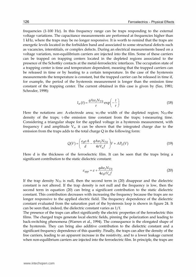
frequencies (1-100 Hz). In this frequency range can be traps responding to the external voltage variations. The capacitance measurements are performed at frequencies higher than 1 kHz, where the traps may be no longer responsive. It is worth to remind that the traps are energetic levels located in the forbidden band and associated to some structural defects such as vacancies, interstitials, or complex defects. During an electrical measurements based on a voltage variation, non-equilibrium carriers are injected into the film. Some of these carriers can be trapped on trapping centers located in the depleted regions associated to the presence of the Schottky contacts at the metal-ferroelectric interfaces. The occupation state of a trapping center is time and temperature dependent, meaning that the trapped carriers can be released in time or by heating to a certain temperature. In the case of the hysteresis measurements the temperature is constant, but the trapped carrier can be released in time if, for example, the period of the hysteresis measurement is longer than the emission time constant of the trapping center. The current obtained in this case is given by (Sze, 1981; Schroder, 1998):
0( ) expt Ttr
qAw N tI t
(18)
Here the notations are: A-electrode area; wt-the width of the depleted region; NT0-the
density of the traps; -the emission time constant from the traps; t-measuring time. Considering a triangular shape for the applied voltage in a hysteresis measurement, with frequency f and amplitude Va, it can be shown that the integrated charge due to the emission from the traps adds to the total charge Q in the following form:
00( ) ( )4
t TS
a
qAw NAQ V V AP V
d V f
(19)
Here d is the thickness of the ferroelectric film. It can be seen that the traps bring a significant contribution to the static dielectric constant:
0
04t T
appa
qdw N
V f (20)
If the trap density NT0 is null, then the second term in (20) disappear and the dielectric constant is not altered. If the trap density is not null and the frequency is low, then the second term in equation (20) can bring a significant contribution to the static dielectric constant. This contribution decreases with increasing the frequency because the traps are no longer responsive to the applied electric field. The frequency dependence of the dielectric constant evaluated from the saturation part of the hysteresis loop is shown in figure 24. It can be seen that, indeed, the dielectric constant varies as 1/f. The presence of the traps can affect significantly the electric properties of the ferroelectric thin films. The charged traps generate local electric fields, pinning the polarization and leading to back-switching phenomena (Warren et al., 1994). The consequence is the elongated shape of the hysteresis. They can bring also additive contribution to the dielectric constant and a significant frequency dependence of this quantity. Finally, the traps can alter the density of the free carriers, leading to an apparent increase in the resistivity, and to a lower leakage current when non-equilibrium carriers are injected into the ferroelectric film. In principle, the traps are
www.intechopen.com

Charge Transport in Ferroelectric Thin Films
127
unavoidable, but their density and types can be reduced by increasing the crystal quality. In the high quality epitaxial films only point defects are expected, thus the extrinsic effects associated to the presence of traps are very much reduced.
Fig. 24. The frequency dependence of the dielectric constant estimated from the linear part of the hysteresis loop (the saturation regime of spontaneous ferroelectric polarization).
5.2 The photoelectric properties of ferroelectrics The ferroelectric materials with perovskite structure can be regarded as wide gap semiconductors if they are in the form of epitaxial thin films. This assumption is valid mainly for PZT and BiFeO3 but can work also in the case of BaTiO3. The presence of the Schottky contacts, with space charge regions near the electrodes, suggests the presence of the photovoltaic effect similar to the one encountered in semiconductor diode devices (Qin et al., 2009; Yang et al., 2009). This effect is different from the bulk photovoltaic effect which is present in the thick films or in massive ferroelectric ceramics and single crystals. Therefore, the short-circuit current was measured and its relation with the ferroelectric polarization was studied (Pintilie L. et al., 2007). A summary of the main results obtained on epitaxial PZT thin films is presented below: - The sign of the short-circuit photocurrent is dependent on the orientation of the
ferroelectric polarization. In the ideal case the sign should change when the polarization orientation is changed. When an important imprint is present in the film, favoring one of the two orientation of ferroelectric polarization then the photocurrent does not change the sign. The fact that the photocurrent changes the sign when the polarization changes the orientation can be speculated in non-volatile memories as a non-destructive readout procedure of the written information (Kholkin et al., 1997) .
- The magnitude of the short-circuit photocurrent depends on the magnitude of the ferroelectric polarization. This is supported by the fact that, for contacts with negligible
www.intechopen.com

Ferroelectrics – Physical Effects
128
imprint, the short-circuit photocurrent describes a hysteresis loop similar to the one described by the ferroelectric polarization when the applied voltage is varied (Yang et al., 2000). Because the magnitude of the polarization is dependent also on the existing imprint in the film, the short-circuit photocurrent is also dependent on the imprint. This fact can be speculated to map the imprint in a ferroelectric film by using a non-destructive method (Pintilie L. et al., 2010).
- The spectral range is in the blue-UV domain. For high quality epitaxial films the maximum sensibility is obtained at wavelengths between 270-290 nm, and can reach values of about 0.1 A/W. This can make the ferroelectric thin films attractive for solid state UV detectors, at least for applications where the magnitude of the generated photo-signal is not so important.
- The ferroelectric Schottky diode shows a significant photovoltaic effect. It was observed that the short-circuit photocurrent is not changing the sign when the polarization orientation was changed by external poling. This is confirming the fact that only one direction of polarization is stable in the ferroelectric Schottky diode.
Short-circuit photocurrent was measured also in polycrystalline films. A typical spectral
distribution is shown in figure 25. Short-circuit current was measured also on BaTiO3 films
(see figure 26), as well as in BiFeO3 films. However, in the last case the magnitude of the
short-circuit photocurrent is very much reduced by the presence of high density of free
carriers, leading to a high recombination rate.
Fig. 25. The spectral distribution of the short-circuit photocurrent measured after poling the
polycrystalline PZT fim with different applied voltages.It was also observed that the short-
circuit photocurrent is present on a large temperature domain (see results presented in
figure 27 for PZT films). This fact offers the possibility to study the possible temperature
dependence of the energy gap in ferroelectric materials with perovskite structures.
www.intechopen.com

Charge Transport in Ferroelectric Thin Films
129
Fig. 26. The spectral distribution of the short-circuit photocurrent in the case of an epitaxial BaTiO3 film. The inset shows the hysteresis loop for the same film. A large imprint is observed, which is consistent with the fact that the short-circuit photocurrent is not changing the sign when the BaTiO3 film is poled with opposite applied electric fields which should impose opposite directions for the ferroelectric polarization.
Fig. 27. The spectral distribution of the short-circuit photocurrent in the case of an epitaxial PZT film, at different temperatures. A shift towards shorter wavelengths of the peak sensitivity can be observed at low temperatures compared to room temperature, which can be related to an increase of the energy gap of the PZT
www.intechopen.com
Ferroelectrics – Physical Effects
130
6. Conclusions
The results presented above shed some light regarding the charge transport in ferroelectric thin films and its intimate relation with the presence of the ferroelectric polarization. The charge transport can impact all the electric/ferroelectric properties of the ferroelectric thin film. Therefore is not advisable to treat or model separately the experimental results obtained by measuring capacitance, current or hysteresis. The proposed model should be able to simulate all the features observed in the experimental characteristics, including voltage, frequency and temperature dependencies. In any case, the technological advance in the deposition methods will allow in the near future a more precise control of the structural defects, especially impurities and vacancies. This will be an important step-forward because will allow a more precise control of the free carrier concentration, type and mobility. On the other hand, the in depth understanding of the metal-ferroelectric interface will allow the leakage current control through the precise engineering of the potential barrier at the interface. All these advances will open new perspectives in manufacturing new ferroelectric electronic devices and sensors.
7. Acknowledgment
The author acknowledges the financial support from the following agencies and projects: Volkswagen Stiftung under Contract No. I/77738; DINAFER-2-CEEX-06-11-44 project funded by Ministry of Education and Research, Romania; German Science Foundation (DFG) through Contract No. SFB 762; Romanian Ministry of Education and Research through the Contract No. PNII-72–149-HETOX; FP7 project IFOX, grant agreement number 246102.
8. References
Angadi, M. A. & Shivaprasad, S. M. (1986). Temperature-dependent resistivity of discontinuous manganese films, Journal of Materials Science Letters, Vol. 5, pp. 405- 407, ISSN 0022-2461
Ang, C. & Yu, Z. (2004). Dielectric behavior of PbZr0.52Ti0.48O3 thin films: Intrinsic and extrinsic dielectric responses, Applied Physics Letters, Vol. 85, No.17, pp. 3821-3823, ISSN: 0003-6951
Boettger, U. & Bryskin, V. (1985). Hopping Conduction is Solids, Akademie Verlag, Berlin, Germany
Chentir, M; Bouyssou,E; Ventura,L. & Anceau, C. (2009). Leakage current evolution versus dielectric thickness in lead zirconate, titanate thin film capacitors, Journal of Applied Physics, Vol.105, No. 6, Article Number 061605, ISSN: 0021-8979
Cohen, R. E. (1992). Origin of Ferroelectricity in perovskite oxides, Nature, Vol. 358, pp. 136-138, ISSN 0028-0836
Cowley, A. M. & Sze, S. M. (1965). Surface states and barrier height of metal-semiconductor systems, Journal of Applied Physics, Vol. 36, No. 10. pp. 3212-3220, ISSN: 0021-8979
Dawber, M.; Rabbe, K. M. & Scott, J. F. (October 2005). Physics of thin-film ferroelectric oxides, Review of Modern Physics, Vol. 77, No. 4, pp. 1083-1130, ISSN 0034-6861
www.intechopen.com

Charge Transport in Ferroelectric Thin Films
131
Demishev, S. V.; Pronin, A. A.; Sluchanko, N. E.; Samarin, N. A.; Lyapin, A. G.; Brazhkin, V. V.; Varfolomeeva, T. D. & Popova, S. V. (2000). 1D–3D Crossover in Hopping Conduction of Carbynes, JETP Letters, Vol. 72, No. 7, pp. 381–384, ISSN 0021-3640
Dong, Y. F.; Wang, S. J.; Feng, Y. P. & Huan, A. C. H. (2006). Chemical tuning of band alignments for metal gate/high-k oxide interfaces, Physical Review B, Vol. 73, No. 4, Article Number 045302, ISSN ISSN 1098-0121
Horii, S.; Yokoyama S.; Nakajima, H. & Horita, S. (1999). Thickness dependence of materials properties in epitaxial Pb(ZrxTi1-x)O3 films on Ir/(100) (ZrO2)1-x(Y2O3)x/(100) Si structures, Japanese Journal of Applied Physics, Vol. 38, pp. 5378-5382, ISSN 0021-4922
Izyumskaya, N.; Alivov, Y.I.; Cho, S. J.; H. Morkoç, H; Lee, H. & Kang, Y. S. (July 2007). Processing, Structure, Properties, and Applications of PZT Thin Films, Critical Reviews in Solid State and Materials Sciences, Vol. 32, pp.111–202, ISSN: 1040-8436
Jiang, A. Q.; Lin, Y. Y. & Tang, T. A. (2007). Interfacial-layer modulation of domain switching current in ferroelectric thin films, Journal of Applied Physics, Vol.101, No. 10, Article Number 104105, ISSN: 0021-8979
Kao, K. C. & Hwang, W. (1981). Electronic Transport in Solids, International series in the Science of the Solid State, vol. 14. General editor B.R. Pamplin, Pergamon Press, Oxford, U. K.
Kholkin, A.; Boiarkine, O. & Setter, N. (1997). Transient photocurrents in lead zirconate titanate thin films, Applied Physics Letters, Vol. 72, No.1, pp. 130-132, ISSN: 0003-6951
Kuroiwa, Y.; Aoyagi, S. & Sawada, A. (2001). Evidence for Pb-O Covalency in Tetragonal PbTiO3, Physical Review Letters, Vol. 87, No. 21, Article Number 217601, ISSN 0031-9007
Levine, J. D. (1971). Schottky barriers anomaly and interface states, Journal of Applied Physics, Vol. 42, No. 10. Pp. 3991-3999, ISSN: 0021-8979
Lines, M. E. & Glass, A. M. (1977). Principles and Applications of Ferroelectrics and Related Materials, Clarendon Press, Oxford, UK
Lohse, O.; Grossmann, M.; Boettger, U.; Bolten, D. & Waser, R. (2001). Relaxation mechanism of ferroelectric switching in Pb.Zr,Ti.O3 thin films, Journal of Applied Physics, Vol.89, No. 4, pp. 2332-2336, ISSN: 0021-8979
Meyer, R; Waser, R.; Prume, K.; Schmitz, T. & Tiedke, S. (2005). Dynamic leakage current compensation in ferroelectric thin-film capacitor structures, Applied Physics Letters, Vol. 86, No.14, Article Number. 142907, ISSN: 0003-6951
Nakamura, Y.; Nakashima, S. & Okuyama, M. (2009). Improvement of ferroelectric properties of BiFeO3 thin films by postmetallization annealing and electric field application, Journal of Applied Physics, Vol.105, No. 6, Article Number 061616, ISSN: 0021-8979
Núñez, M. & Nardelli, M. B (2008). Interface phase and tuning of polarization in metal-ferroelectric junctions: A theoretical study, Applied Physics Letters, Vol. 92, No.25, Article Number. 252903, ISSN: 0003-6951
Pabst, G. W.; Martin, L. W.; Chu, Y. & Ramesh, R. (2007), Leakage mechanisms in BiFeO3 thin films, Applied Physics Letters, Vol. 90, No.7, Article Number. 072902, ISSN: 0003-6951
www.intechopen.com

Ferroelectrics – Physical Effects
132
Petraru, A.; Pertsev, N. A.; Kohlstedt, H.; Poppe, U.; Waser, R.; Solbach, A. & Klemradt, U. (2007). Polarization and lattice strains in epitaxial BaTiO3 films grown by high-pressure sputtering, Journal of Applied Physics, Vol.101, No. 11, Article Number 114106, ISSN: 0021-8979
Picinin, A.; Lente, M. H.; Eiras, J. A. & Rino, J. P. (2004). Theoretical and experimental investigations of polarization switching in ferroelectric materials, Physical Review B, Vol. 69, No. 6, Artcle Number 064117, ISSN 1098-0121
Pintilie, L. &Alexe, M. (December 2005). Metal-Ferroelectric-Metal heterostructures with Schottky contacts I. Influence of the ferroelectric properties, Journal of Applied Physics, Vol. 98, No. 12, Article Number 123103, ISSN: 0021-8979
Pintilie, L.; Boerasu, I.; Gomes, M.J.M.; Zhao, T.; Ramesh, R. & Alexe, M. (December 2005), Metal-ferroelectric-metal structures with Schottky contacts. II. Analysis of the experimental current-voltage and capacitance-voltage characteristics of Pb(Zr,Ti)O-3 thin films, Journal of Applied Physics, Vol. 98, No. 12, Article Number 123104, ISSN: 0021-8979
Pintilie, L.; Vrejoiu, I.; Hesse, D.; LeRhun, G. & Alexe, M. (March 2007), Ferroelectric polarization-leakage current relation in high quality epitaxial Pb(Zr, Ti)O-3 films, Physical Review B, Vol. 75, No. 10, Article Number 104103, ISSN: 1098-0121
Pintilie, L.; Vrejoiu, I.; Rhun, G. Le & Alexe, M. (March 2007). Short-circuit photocurrent in epitaxial lead zirconate-titanate thin films, Journal of Applied Physics, Vol.101, No. 6, Article Number 064109, ISSN: 0021-8979
Pintilie L. (March 2009). Advanced electrical characterization of ferroelectric thin films: facts and artifacts, Journal of Optoelectronics and Advanced Materials, Vol. 11, No.3, pp.215-228 , ISSN: 1454-4164
Pintilie, L.; Dragoi, C.; Chu, Y. H.; Martin, L. W.; Ramesh, R. & Alexe, M. (June 2009), Orientation-dependent potential barriers in case of epitaxial Pt-BiFeO3-SrRuO3 capacitors, Applied Physics Letters, Vol. 94, No.23, Article Number. 232902, ISSN: 0003-6951
Pintilie, L.; Vrejoiu, I.; Hesse, D. & Alexe, M. (2008). The influence of the top-contact metal on the ferroelectric properties of epitaxial ferroelectric Pb(Zr0.2Ti0.8)O3 thin films, Journal of Applied Physics, Vol.104, No. 11, Article Number 114101, ISSN: 0021-8979
Pintilie, L.; Stancu, V.; Vasile, E. & Pintilie, I. (2010). About the complex relation between short-circuit photocurrent, imprint and polarization in ferroelectric thin films, Journal of Applied Physics, Vol.107, No. 11 Article Number 114111, ISSN: 0021-8979
Prabhumirashi, P. & Dravid, V. P. (2005). Atomic-scale manipulation of potential barriers at SrTiO3 grain boundaries, Applied Physics Letters, Vol. 87, No.12, Article Number 121917, ISSN: 0003-6951
Qin, M.; Yao, K. & Liang, Y. C. (2009). Photovoltaic characteristics in polycrystalline and epitaxial (Pb0.97La0.03)(Zr0.52Ti0.48)O3 ferroelectric thin films sandwiched between different top and bottom electrodes, Journal of Applied Physics, Vol.105, No. 6, Article Number 061624, ISSN: 0021-8979
Rybickiy, J.; Rybickay, A.; Feliziani, S. & Chybicki, M. (1996). The thickness dependence of the hopping time-of-flight current profiles in spatially non-uniform thin dielectric, layers, J. Phys.: Condens. Matter, Vol. 8, pp. 2089–2093, ISSN 0953-8984
www.intechopen.com
Charge Transport in Ferroelectric Thin Films
133
Sai, N.; Rabe, K. M. & Vanderbilt, D. (2002). Theory of structural response to macroscopic electric fields in ferroelectric systems, Physical Review B, Vol. 66, No. 10, Article Number 104108, ISSN ISSN 1098-0121
Schroeder, D. K. (1998). Semiconductor material and device characterization, Wiley-Interscience, New York, USA, ISBN 0-471-24139-3
Scott, J. F. (2000). Ferroelectric Memories, in Advanced Microelectronics Series, edited by K. Itoh and T. Sakurai, Springer-Verlag, Berlin, Heidelberg, Germany
Shelke, V.; Harshan, V. N.; Kotru, S. & Gupta, A. (2009). Effect of kinetic growth parameters on leakage current and ferroelectric behavior of BiFeO3 thin films, Journal of Applied Physics, Vol.106, No. 10, Article Number 104114, ISSN: 0021-8979
Shur, V. Ya.; Nikolaeva, E. V.; Shishkin, E. I.; Kozhevnikov, V. L.; Chernykh, A. P.; Terabe, K. & Kitamura, K. (2001). Polarization reversal in congruent and stoichiometric lithium tantalite, Applied Physics Letters, Vol. 79, No.19, pp. 3146-3148, ISSN: 0003-6951
Simmons, J. G. (1965). Richardson-Schottky in solids, Physical Review Letters, Vol. 15, No. 25, pp. 967-968, ISSN 0031-9007
Sze, S. M. (1981). Physics of Semiconductor Devices, 2nd ed. John Wiley & Sons, USA, ISBN 0-471-05661-8
Tagantsev, A. K.; Stolichnov, I.; Setter, N.; Cross J. C. & Tsukada, M. (2002). Non-Kolmogorov-Avrami switching kinetics in ferroelectric thin films, Physical Review B, Vol. 66, Artcle Number 214109, ISSN 1098-0121
Tang, X. G.; Wang, J.; Zhang, Y. W. & Chan H. L. W. (2003), Leakage current and relaxation characteristics of highly .111.-oriented lead calcium titanate thin films, Journal of Applied Physics, Vol.94, No. 8, pp. 5163-5166, ISSN: 0021-8979
Uchino, K. (200). Ferroelectric Devices, Marcel Dekker, New York, SUA Vrejoiu, I.; Le Rhun, G.; Zakharov, N. D.; Hesse, D.; Pintilie, L. & Alexe, M. (October 2006),
Threading dislocations in epitaxial ferroelectric PbZr0.2Ti0.8O3 films and their effect on polarization backswitching, Philosophical Magazine, Vol.86, No.28, pp. 4477-4486, ISSN: 1478-6435
Vrejoiu, I.; Le Rhun, G.; Pintilie, L.; Hesse, D.; Alexe, M. & Goesele, U. (July 2006), Intrinsic ferroelectric properties of strained tetragonal PbZr0.2Ti0.8O3 obtained on layer-by-layer grown, defect-free single-crystalline films, Advanced Materials, Vol.18, No.13, pp.1657-+, ISSN: 0935-9648
Wang, J.; Neaton, J. B.; Zheng, H.; Nagarajan, V.; Ogale, S. B.; Liu, B.; Viehland, D.; Vaithyanathan, V.; Schlom, D. G.; Waghmare, U. V.; Spaldin, N. A.; Rabe, K. M.; Wuttig, M. & Ramesh, R. (2003). Epitaxial BiFeO3 Multiferroic Thin Film Heterostructures, Science, Vol. 299, pp. 1719-1722, ISSN 0036-8075
Warren, W. L.; Dimos, D.; Tuttle, B. A.; Nasby, R. D. & Pike, G. E. (1994). Electronic domain pinning in Pb(Zr,Ti)03 thin films and its role in fatigue, Applied Physics Letters, Vol. 65, No.8, pp. 1018-1020, ISSN: 0003-6951
Wu, A; Vilarinho, P. M.; Wu, D. & Gruverman, A. (2008). Abnormal domain switching in Pb(Zr,Ti)O3 thin film capacitors, Applied Physics Letters, Vol. 93, No.26, Article Number 262906, ISSN: 0003-6951
Yang, Y. S.; Lee, S. J.; Yi, S.; Chae, B. G.; Lee, S. H.; Joo, H. J. & Jang, M. S. (2000). Schottky barrier effects in the photocurrent of sol–gel derived lead zirconate titanate thin film capacitors, Applied Physics Letters, Vol. 76, No.6, pp. 774-776, ISSN: 0003-6951
www.intechopen.com
Ferroelectrics – Physical Effects
134
Yang, S. Y.; Martin, L. W.; Byrnes, S. J.; Conry, T. E.; Basu, S. R.; Paran, D.; Reichertz, L.; Ihlefeld, J.; Adamo, C.; Melville, A.; Chu, Y.-H.; Yang, C.-H.; Musfeldt, J. L.; Schlom, D. G.; Ager III, J. W. & Ramesh, R. (2009). Photovoltaic effects in BiFeO3, Applied Physics Letters, Vol. 95, No.6, Article Number 062909, ISSN: 0003-6951
Zhao, W. & Jena, D. (2004). Dipole scattering in highly polar semiconductor alloys, Journal of Applied Physics, Vol. 96, No. 4. pp. 2095-2101, ISSN: 0021-8979
Zubko, P.; Jung, D. J.; & Scott, J. F. (2006). Space charge effects in ferroelectric thin films, Journal of Applied Physics, Vol.100, No. 11, Article Number 114112, ISSN: 0021-8979
www.intechopen.com

Ferroelectrics - Physical EffectsEdited by Dr. Mickaël Lallart
ISBN 978-953-307-453-5Hard cover, 654 pagesPublisher InTechPublished online 23, August, 2011Published in print edition August, 2011
InTech EuropeUniversity Campus STeP Ri Slavka Krautzeka 83/A 51000 Rijeka, Croatia Phone: +385 (51) 770 447 Fax: +385 (51) 686 166www.intechopen.com
InTech ChinaUnit 405, Office Block, Hotel Equatorial Shanghai No.65, Yan An Road (West), Shanghai, 200040, China Phone: +86-21-62489820 Fax: +86-21-62489821
Ferroelectric materials have been and still are widely used in many applications, that have moved from sonartowards breakthrough technologies such as memories or optical devices. This book is a part of a four volumecollection (covering material aspects, physical effects, characterization and modeling, and applications) andfocuses on the underlying mechanisms of ferroelectric materials, including general ferroelectric effect,piezoelectricity, optical properties, and multiferroic and magnetoelectric devices. The aim of this book is toprovide an up-to-date review of recent scientific findings and recent advances in the field of ferroelectricsystems, allowing a deep understanding of the physical aspect of ferroelectricity.
How to referenceIn order to correctly reference this scholarly work, feel free to copy and paste the following:
Lucian Pintilie (2011). Charge Transport in Ferroelectric Thin Films, Ferroelectrics - Physical Effects, Dr.Mickaël Lallart (Ed.), ISBN: 978-953-307-453-5, InTech, Available from:http://www.intechopen.com/books/ferroelectrics-physical-effects/charge-transport-in-ferroelectric-thin-films