Embed Size (px)
Citation preview

Recommendation ITU-R M.1796-2(02/2014)
Characteristics of and protection criteria for terrestrial radars operating
in the radiodetermination service in the
frequency band 8 500-10 680 MHz
M SeriesMobile, radiodetermination, amateur
and related satellite services

ii Rec. ITU-R M.1796-2
Foreword
The role of the Radiocommunication Sector is to ensure the rational, equitable, efficient and economical use of the radio-frequency spectrum by all radiocommunication services, including satellite services, and carry out studies without limit of frequency range on the basis of which Recommendations are adopted.
The regulatory and policy functions of the Radiocommunication Sector are performed by World and Regional Radiocommunication Conferences and Radiocommunication Assemblies supported by Study Groups.
Policy on Intellectual Property Right (IPR)
ITU-R policy on IPR is described in the Common Patent Policy for ITU-T/ITU-R/ISO/IEC referenced in Annex 1 of Resolution ITU-R 1. Forms to be used for the submission of patent statements and licensing declarations by patent holders are available from http://www.itu.int/ITU-R/go/patents/en where the Guidelines for Implementation of the Common Patent Policy for ITU-T/ITU-R/ISO/IEC and the ITU-R patent information database can also be found.
Series of ITU-R Recommendations(Also available online at http://www.itu.int/publ/R-REC/en)
Series Title
BO Satellite deliveryBR Recording for production, archival and play-out; film for televisionBS Broadcasting service (sound)BT Broadcasting service (television)F Fixed serviceM Mobile, radiodetermination, amateur and related satellite servicesP Radiowave propagationRA Radio astronomyRS Remote sensing systemsS Fixed-satellite serviceSA Space applications and meteorologySF Frequency sharing and coordination between fixed-satellite and fixed service systemsSM Spectrum managementSNG Satellite news gatheringTF Time signals and frequency standards emissionsV Vocabulary and related subjects
Note: This ITU-R Recommendation was approved in English under the procedure detailed in Resolution ITU-R 1.
Electronic PublicationGeneva, 2014
ITU 2014
All rights reserved. No part of this publication may be reproduced, by any means whatsoever, without written permission of ITU.

RECOMMENDATION ITU-R M.1796-2Characteristics of and protection criteria for terrestrial radars operating
in the radiodetermination service in the frequencyband 8 500-10 680 MHz*
(2007-2012-2014)
Scope
This Recommendation provides the technical and operational characteristics and protection criteria for radiodetermination systems operating in the frequency band 8 500-10 680 MHz. It was developed with the intention to support sharing studies in conjunction with Recommendation ITU-R M.1461 addressing analysis procedures for determining compatibility between radars operating in the radiodetermination service and other services.
Keywords
Radar, Protection criteria, Search radar, Interference, radiodetermination
Abbreviations/Glossary
CFAR Constant-false-alarm-rate
IMO International Maritime Organization
pps Pulses per second
SART Search and rescue transponder
The ITU Radiocommunication Assembly,
considering
a) that antenna, signal propagation, target detection, and large necessary bandwidth characteristics of radars to achieve their functions are optimum in certain frequency bands;
b) that the technical characteristics of radiodetermination radars are determined by the mission of the system and vary widely even within a frequency band;
c) that ITU-R is considering the potential for the introduction of new types of systems or services in frequency bands between 420 MHz and 34 GHz used by radars in the radiodetermination service;
d) that representative technical and operational characteristics of radars operating in the radiodetermination service are required to determine, if necessary, the feasibility of introducing new types of systems into frequency bands allocated to the radiodetermination service,
noting
a) that technical and operational characteristics of maritime radar beacons operating in the frequency band 9 300-9 500 MHz are to be found in Recommendation ITU-R M.824;
b) that technical parameters of radar target enhancers operating in the frequency band 9 300-9 500 MHz are to be found in Recommendation ITU-R M.1176;
* Characteristics of meteorological ground-based radars operating in this frequency band are contained in Recommendation ITU-R M.1849.

2 Rec. ITU-R M.1796-2
c) that technical and operational characteristics of search and rescue radar transponders (SART) operating in the frequency band 9 200-9 500 MHz are to be found in Recommendation ITU-R M.628,
recognizing
a) that the required protection criteria depend upon the specific types of interfering signals;
b) that the application of protection criteria may require consideration for the inclusion of the statistical nature of the application of those criteria and other elements of the methodology for performing compatibility studies (e.g. propagation loss). Further development of these statistical considerations, together with the required probability of detection for various maritime operational scenarios may be incorporated into future revisions of this Recommendation, as appropriate,
recommends
1 that the technical and operational characteristics of the radiodetermination radars described in Annex 1 should be considered representative of those operating in the frequency band 8 500-10 680 MHz;
2 that this Recommendation, in conjunction with Recommendation ITU-R M.1461, should be used in analysing compatibility between radiodetermination radars and systems in other services;
3 that the criterion of interfering signal power to radar receiver noise power level, an I/N ratio of −6 dB, should be used as the required protection level for radiodetermination radars in the frequency band 8 500-10 680 MHz, even if multiple interferers are present (see Note 1);
4 that the results of interference susceptibility trials performed on shipborne radionavigation radars operating in the frequency band 9 200-9 500 MHz, which are contained in Annex 3, should be used in assessing interference into shipborne radionavigation radars, noting that the results are for non-fluctuating targets and that radar cross-section (RCS) fluctuations should be taken into account.
NOTE 1 – Further information is provided in Annex 2.
Annex 1
Technical and operational characteristics of radars in the radiodetermination service in the frequency band 8 500-10 680 MHz
1 Introduction
The characteristics of radiodetermination radars operating worldwide in the frequency band 8 500-10 680 MHz are presented in Tables 1, 2, 3 and 4, and described further in the following paragraphs.
2 Technical characteristics
The frequency band 8 500-10 680 MHz is used by many different types of radars on land-based, transportable, shipboard, and airborne platforms. Radiodetermination functions performed in the

Rec. ITU-R M.1796-2 3
frequency band include airborne and surface search, ground-mapping, terrain-following, navigation (both aeronautical and maritime), target-identification, and meteorological (both airborne and ground-based). Other major differences among the radars include transmit duty cycles, emission bandwidths, presence and types of intra-pulse modulation, frequency-agile capabilities of some, transmitter peak and average powers, and types of transmitter RF power devices. These characteristics, individually and in combination, all have major bearing on the compatibility of the radars with other systems in their environment, while other characteristics affect that compatibility to lesser degrees. Radar operating frequencies can be assumed to be uniformly spread throughout each radar’s tuning frequency band. Tables 1, 2, 3 and 4 contain technical characteristics of representative radiolocation and radionavigation radars deployed in the frequency band 8 500-10 680 MHz with the exception of ground based meteorological radars, which are contained in Recommendation ITU-R M.1849.
The major radiolocation radars operating in this frequency band are primarily used for detection of airborne objects. They are required to measure target altitude as well as range and bearing. Some of the airborne targets are small and some are at ranges as great as 300 nautical miles (~ 556 km), so these radiolocation radars must have great sensitivity and must provide a high degree of suppression to all forms of clutter return, including that from sea, land, and precipitation. In some cases, the radar emissions in this frequency band are required to trigger radar beacons.
Largely because of these mission requirements, the radars using this frequency band tend to possess the following general characteristics:– they tend to have low to medium (from 1 W to 250 000 W) transmitter peak and average
power, with notable exceptions;– they typically use master-oscillator power-amplifier transmitters rather than power
oscillators. They are usually tunable, and some of them are frequency-agile. Some of them use linear – or non-linear – FM (chirp) or phase-coded intra-pulse modulation;
– some of them have antenna main beams that are steerable in one or both angular dimensions using electronic beam steering;
– they typically employ versatile receiving and processing capabilities, such as auxiliary sidelobe-blanking receive antennas, processing of coherent-carrier pulse trains to suppress clutter return by means of moving-target-indication, constant-false-alarm-rate (CFAR) techniques, and, in some cases, adaptive selection of operating frequencies based on sensing of interference on various frequencies;
– individual radars often have numerous different pulse widths and pulse repetition frequencies; some chirp radars have a choice of chirp bandwidths; and some frequency-agile radars have a variety of agile- or fixed-frequency modes. This flexibility can provide useful tools for maintaining compatibility with other radars in the environment.
Some or all of the radars whose characteristics are presented in Tables 1, 2, 3 and 4 possess these properties. Those Tables are extensive to exemplify the wide variety of radar missions, platforms, waveforms, bandwidths, duty cycles, power levels, transmitter devices, etc. found in radars using this frequency band, although they do not illustrate the full repertoire of attributes that might appear in future systems.

4 Rec. ITU-R M.1796-2
TABLE 1
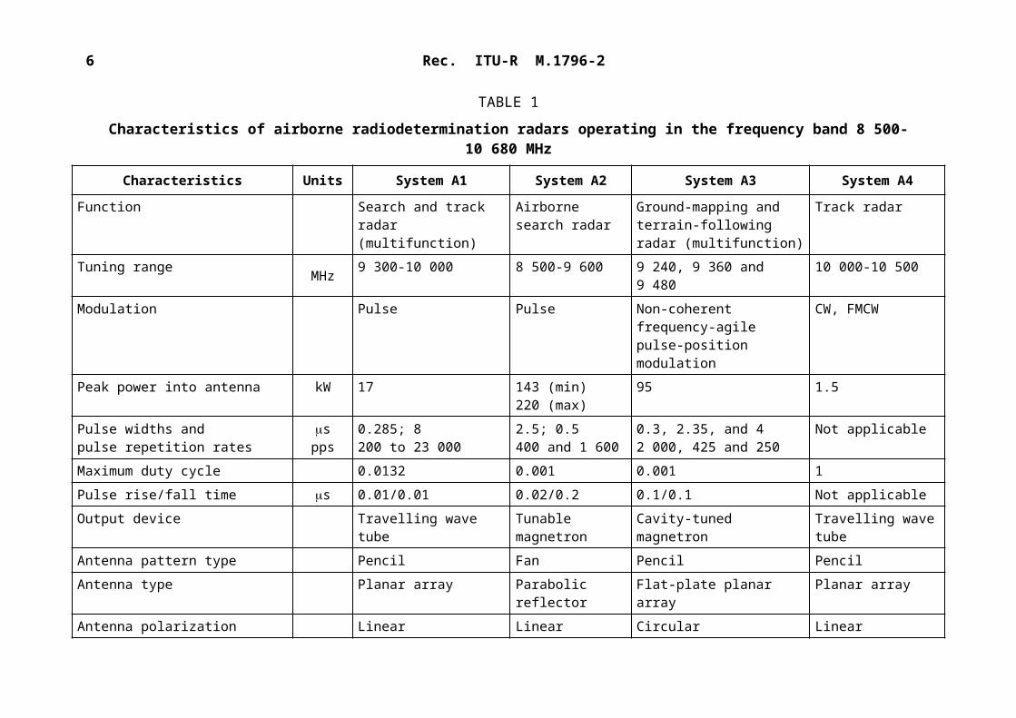
Characteristics of airborne radiodetermination radars operating in the frequency band 8 500-10 680 MHz
Characteristics Units System A1 System A2 System A3 System A4
Function Search and track radar (multifunction)
Airborne search radar
Ground-mapping and terrain-following radar (multifunction)
Track radar
Tuning range MHz 9 300-10 000 8 500-9 600 9 240, 9 360 and 9 480 10 000-10 500Modulation Pulse Pulse Non-coherent frequency-agile
pulse-position modulationCW, FMCW
Peak power into antenna kW 17 143 (min)220 (max)
95 1.5
Pulse widths and pulse repetition rates
spps
0.285; 8200 to 23 000
2.5; 0.5400 and 1 600
0.3, 2.35, and 42 000, 425 and 250
Not applicable
Maximum duty cycle 0.0132 0.001 0.001 1Pulse rise/fall time s 0.01/0.01 0.02/0.2 0.1/0.1 Not applicableOutput device Travelling wave tube Tunable magnetron Cavity-tuned magnetron Travelling wave tubeAntenna pattern type Pencil Fan Pencil PencilAntenna type Planar array Parabolic reflector Flat-plate planar array Planar arrayAntenna polarization Linear Linear Circular LinearAntenna main beam gain dBi 32.5 34 28.3 35.5Antenna elevation beamwidth degrees 4.6 3.8 5.75 2.5Antenna azimuthal beamwidth degrees 3.3 2.5 5.75 2.5Antenna horizontal scan rate degrees/
s236(118 scans/min)
36 or 72(6 or 12 rpm)
Up to 106(Up to 53 scans/min)
90
Antenna horizontal scan type (continuous, random, sector, etc.)
Sector: 60 (mechanical) 360 (mechanical) Sector: 60 (mechanical) Sector: 60 (mechanical)

Rec. ITU-R M.1796-2 5
TABLE 1 (continued)
Characteristics Units System A1 System A2 System A3 System A4
Antenna vertical scan rate degrees/s 118(59 scans/min)
Not applicable 148.42(Up to 137 scans/min)
90
Antenna vertical scan type Sector: 60 (mechanical)
Not applicable Sector: +25/40 (mechanical) Sector: 60 (mechanical)
Antenna side-lobe (SL) levels (1st SLs and remote SLs) dBi 7.5 at 15 Not specified 5.3 at 10 Not specified
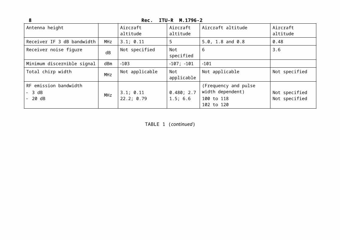
Antenna height Aircraft altitude Aircraft altitude
Aircraft altitude Aircraft altitude
Receiver IF 3 dB bandwidth MHz 3.1; 0.11 5 5.0, 1.8 and 0.8 0.48Receiver noise figure dB Not specified Not specified 6 3.6Minimum discernible signal dBm 103 107; 101 101Total chirp width MHz Not applicable Not applicable Not applicable Not specifiedRF emission bandwidth 3 dB 20 dB
MHz 3.1; 0.1122.2; 0.79
0.480; 2.71.5; 6.6
(Frequency and pulse width dependent)100 to 118102 to 120
Not specifiedNot specified
TABLE 1 (continued)

6 Rec. ITU-R M.1796-2Characteristics Units System A5 System A6a(1) System A6b(1)
Function Weather avoidance including wind-shear detection (navigation)
Weather avoidance (WA), including wind-shear detection (WS) (navigation)
Ground-mapping, including:Monopulse ground mapping (MGM) and Doppler beam sharpening (DBS)
Tuning range MHz 9 330 9 305-9 410WA: frequency agile pulse-to-pulse ( 2 000 hops/s);WS: adaptive single frequency
9 360 and 9 305-9 410MGM: frequency agile pulse-to-pulse ( 600 hops/s);DBS: single frequency (9 360)
Modulation Pulse WA: unmodulated and Barker-coded (5:1 and 13:1) pulses;WS: unmodulated pulses
MGM and DBS: Barker-coded (13:1) pulses
Peak power into antenna W 150 150 150Pulse width andPulse repetition rate
spps
1 to 20180 to 9 000
WA: 0.2-230; WS: 2WA: 2 000 pps for 0.2-6 s pulses, decreasing to 230 pps for 230 s pulses;WS: 3 600-3 940 pps
MGM: 1.3-260; DBS: 0.64-20MGM: 600 pps for 1.3-60 s pulses, decreasing to 220 pps for 260 s pulses;DBS: 700-1 600 pps for all pulse widths
Maximum duty cycle Not specified WA: 0.054;WS: 0.0076
MGM: 0.057;DBS: 0.033 (0.024 long term)
Pulse rise/fall time s Not specified WA: 0.02-0.05/0.01;WS: 0.02/0.01
MGM: 0.01-0.02/0.01-0.02;DBS: 0.02-0.04/0.01
Output device Solid state FET FETAntenna pattern type Pencil Pencil FanAntenna type Planar array Planar array Planar arrayAntenna polarization Not specified Linear LinearAntenna main beam gain dBi 34.4 32 28.7Antenna elevation beamwidth
degrees 3.5 4 42
Rec. ITU-R M.1796-2 7TABLE 1 (continued)
Characteristics Units System A5 System A6a(1) System A6b(1)
Antenna azimuthal beamwidth
degrees 3.5 2.7 2.7
Antenna horizontal scan rate degrees/s Not specified 200( 40 scans/min)
200( 40 scans/min)
Antenna horizontal scan type (continuous, random, sector, etc.)
Sector: 30 Sector: 15 to 135 (mechanical) Sector: 15 to 135 (mechanical)
Antenna vertical scan rate Not specified 20 scans/min Not applicableAntenna vertical scan type (continuous, random, sector, etc.)
Not specified 1 or 2 horizontal bars(mechanical)
Not applicable
Antenna side-lobe (SL) levels (1st SLs and remote SLs)
dBi +3.4 8 at 4.2 3.7 at 4.5
Antenna height Aircraft altitude Aircraft altitude (wind-shear at low altitude)
Aircraft altitude
Receiver IF 3 dB bandwidth MHz Not specified WA: 16 for narrow pulses/subpulses, decreasing to 0.8 for wide pulses/subpulses;WS: 0.8
Receiver noise figure dB 4.0 5 5Minimum discernible signal dBm 125 110 110Chirp bandwidth MHz Not applicable Not applicable Not applicableRF emission bandwidth MHz Not specified For shortest plain pulse to longest
subpulse:WA: 3 dB: 5 to 0.052;
20 dB: 40.5 to 0.37;WS: 3 dB: 0.46
20 dB: 3.28
For shortest to longest subpulses:MGM: 3 dB: 7.68 to 0.045;
20 dB: 59 to 0.31DBS: 3 dB: 18 to 0.6;
20 dB: 150 to 4.1

8 Rec. ITU-R M.1796-2TABLE 1 (continued)
Rec. ITU-R M.1796-2 9Characteristics Units System A7a, A7b, and A7c(2) System A7d(2) System A7e and
A7f(2)System A8
Function Surface search and SAR imaging
Navigation Inverse SAR imaging Search (radiolocation)Weather
Tuning range MHz 9 380-10 120 Frequency agile pulse-to-pulse over 340 MHz
9 380-10 120 9 250-9 440, frequency-agile pulse-to-pulse, 20 MHz steps
Modulation Linear FM pulse Linear FM pulse Linear FM pulse FM pulsePeak power into antenna kW 50 50 50 10Pulse width andpulse repetition rate
spps
Search: 5 s @ 1 600-2 000 or 10 s @ approx. 380 SAR: 13.5 s @ 250-750
10Approx. 380
10470, 530, 800 and 1 000
5 and 172 500, 1 500, 750 and 400(all pulse widths)
Maximum duty cycle 0.010 (5 s & 13.5 s);0.004 (10 s)
0.004 0.010 0.04
Pulse rise/fall time s 0.1/0.1 0.1/0.1 0.1/0.1 0.1/0.1Output device Travelling wave tube Travelling wave tube Travelling wave tube Travelling wave tubeAntenna pattern type Pencil/fan Pencil/fan Pencil/fan FanAntenna type Parabolic reflector Parabolic reflector Parabolic reflector Slotted arrayAntenna polarization Horizontal Horizontal Horizontal Vertical and horizontalAntenna main beam gain dBi 34.5 34.5 34.5 32Antenna elevation beamwidth
degrees 4.0 4.0 4.0 9.0
Antenna azimuthal beamwidth
degrees 2.4 2.4 2.4 1.8
Antenna horizontal scan rate
degrees/s 36, 360, and 1 800 36, 360, 1 800 36, 360, and 1 800 90 or 360(15 or 60 rpm)
TABLE 1 (continued)

10 Rec. ITU-R M.1796-2Characteristics Units System A7a, A7b, and A7c(2) System A7d(2) System A7e and A7f(2) System A8
Antenna horizontal scan type (continuous, random, sector, etc.)
10° sector 10° sector 10° sector 360
Antenna vertical scan rate
degrees/s
Not applicable Not applicable Not applicable Not applicable
Antenna vertical scan type (continuous, random, sector, etc.)
Selectable tilt0/–90
Selectable tilt0/–90
Selectable tilt0/–90
Selectable tilt+15/–15
Antenna sidelobe (SL) levels (1st SLs and remote SLs)
dBi 14.5 at 12 14.5 at 12 14.5 at 12 20
Antenna height Aircraft altitude Aircraft altitude Aircraft altitude Aircraft altitudeReceiver IF 3 dB bandwidth
MHz Not specified Not specified Not specified 16
Receiver noise figure dB 5 5 5 Not specifiedMinimum discernible signal
dBm Depends on processing gain (34 dB (5 s), 30 dB (10 s) and 39.5 dB (13.5 s) for one return pulse)
Depends on processing gain (17 dB for one return pulse)
Depends on processing gain (30 dB (100 MHz) or 33 dB (200 MHz) for one return pulse)
–98
Total chirp width MHz Search: 500 (5 s) or 100 (10 s)SAR: 660
5 100 or 200 10
RF emission bandwidth
– 3 dB– 20 dB
MHz Search (5 s) Search (10 s)SAR
470 95 640540 110 730
4.57.3
100 MHz chirp
95110
200 MHz chirp
190220
9.312
TABLE 1 (continued)

Rec. ITU-R M.1796-2 11Characteristics Units System A9 System A10 System A11 System A12
Function Weather avoidance, search and rescue, ground mapping
Weather avoidance, ground mapping, search
Weather avoidance, ground mapping, search and rescue
Multipurpose Surveillance, scanning, Tracking
Tuning range MHz Radar: 9 375 10;Beacon: 9 310
Preheat pulse: 9 337 and 9 339 (precedes each operational pulse)Operational pulse: 9 344
9 375 ± 30 8 500-10 450
Modulation Pulse Pulse Pulse Adaptive Pulse, FM, linear FM pulse (chirp)
Peak power into antenna kW 25 0.026 (14 dBW) 2.5 to 6.0 0.03-10Pulse width andPulse repetition rate
spps
4.5, 2.4, 0.8 and 0.2 µs at 180, 350, 350 and 1 000 pps
9 337 and 9 339 MHz: 1-29 s at 2 200-220 pps(dithered) for all pulse widths;9 344 MHz: 1.7-2.4, 2.4-4.8, 4.8-9.6, 17, 19 and 29 s at 2 200-220 pps (dithered)
Fixed at 4106.5
0.15-300 adaptive1 000-50 0000 adaptive
Maximum duty cycle 0.00082 9 337 and 9 339 MHz: 0.0649 344 MHz: 0.011 (with 17 s pulses)
0.00043 0.01-0.8 (pulse), 1 (FM)
Pulse rise/fall time s Not specified 9 337 and 9 339 MHz: 0.3/0.29 344 MHz: 0.5/0.5
Rise time: 0.3 Fall time: 0.4
Not specified
Output device High-reliability magnetron IMPATT diode Magnetron Solid stateAntenna pattern type Pencil and fan Pencil Pencil Digital beamformingAntenna type Flat-plate array Flat array Flat array Active arrayAntenna polarization Horizontal and vertical Horizontal Horizontal Lin/circularAntenna main beam gain dBi Pencil: 30; fan: 29 29 26.7 35-42Antenna elevation beamwidth
degrees Pencil: 3; fan: 6 < 10 8.1 1.6 @42 dBi
Antenna azimuthal beamwidth
degrees/s Pencil: 3; fan: 3 7 8.1 1.6 @42 dBi
TABLE 1 (continued)

12 Rec. ITU-R M.1796-2Characteristics Units System A9 System A10 System A11 System A12
Antenna horizontal scan rate degrees/s 72 (long-range), 270 (short-range)(360°: 12 rpm (long-range), 45 rpm (short-range))Sector: not specified
30 25 Not applicable
Antenna horizontal scan type (continuous, random, sector, etc.)
Continuous (360)Sector (90)
Sector 60° or 120 Sector volume (90 or 120)
±60° Electronic scan±120° with additional mechanical repositioner
Antenna vertical scan rate degrees/s Not applicable Not applicable Not applicable Not applicableAntenna vertical scan type (continuous, random, sector, etc.)
Not applicable Operator-selected tilt: 30 Sector volume: 30 ±60° Electronic scan±120° with additional mechanical repositioner
Antenna side-lobe (SL) levels (1st SLs and remote SLs)
dBi Not specified +13.9 +4.7 depend on beamforming
Antenna height Aircraft altitude Aircraft altitude Aircraft altitude Aircraft altitudeReceiver IF 3 dB bandwidth MHz Not specified 2.0 1.0 not specifiedReceiver noise figure dB 6.5 2 5 6Minimum discernible signal dBm Not specified –128 (detection sensitivity
after processing)–110 –130
Total chirp width MHz Not applicable Not applicable Not applicable Maximum 1.5 GHz for chirp modulation
RF emission bandwidth– 3 dB
– 20 dB
MHzNot specified
Not specified
–3 dB:9 337 and 9 339 MHz: 0.7 9 344 MHz: 0.4, 0.25, 0.150, 075, 0.08, and 0.05–20 dB:9 337 and 9 339 MHz: 3.69 344 MHz: 1.8, 1.5, 0.8, 0.375, 0.35, and 0.2
–3 dB:0.5
–20 dB:1.5
Depending of operation mode
Depending of operation mode
(1) Multimode radar; also has a beacon-interrogator mode at 9 375 MHz, not described herein.(2) Multimode radar.

Rec. ITU-R M.1796-2 13TABLE 1 (continued)
Characteristics Units System A13
Function Unmanned Aircraft Detect and Avoid RadarTuning range MHz 8 750-8 850 or
9 300-9 500(selected to be compatible with other onboard avionics)
Modulation Pulsed with intrapulse binary phase code; 3 dB bandwidth = 5 MHzPeak power into antenna kW 0.640 (net radiated)Pulse width andPulse repetition rate
spps
0.2 to 30 500 to 60 000(mode-dependent)
Maximum duty cycle 0.16Pulse rise/fall time s 0.1/0.1Output device Solid-state power amplifiersAntenna pattern type Elliptical beam cross-sectionAntenna type Active electronically scanned array (AESA)Antenna polarization Linear verticalAntenna main beam gain dBi 28Antenna elevation beamwidth degrees 13.5 at antenna broadsideAntenna azimuthal beamwidth degrees 2.7 at antenna broadside

14 Rec. ITU-R M.1796-2
TABLE 1 (end)
Characteristics Units System A13
Antenna horizontal scan rate degrees/s Raster: 8 frames/min with interleaved track updates as requiredAntenna horizontal scan type (continuous, random, sector, etc.)
degrees Sector: 110, electronically scanned (2 antennas are used)
Antenna vertical scan rate degrees/s Raster: 8 frames/min with interleaved track updates as requiredAntenna vertical scan type (continuous, random, sector, etc.)
degrees Sector: 15 (search), 45 (track);electronically scanned; field of regard is electronically stabilized with respect to a local horizontal plane
Antenna side-lobe (SL) levels (1st SLs and remote SLs)
dBi <17, first sidelobe;<13, outer sidelobes;(applies to transmit sidelobe levels with uniform weighting; receive sidelobe levels are lower)
Antenna height equal to aircraft altitudeReceiver IF 3 dB bandwidth MHz 5-10
(mode-dependent)Receiver noise figure dB 4.4 (system NF)Minimum discernible signal dBm 129 for 10 dB SNR (equivalent signal power at the output of a lossless passive receive
antenna, excluding antenna gain and including digital signal processing gain)Total chirp width MHz 10 if chirp is used (for possible growth modes);
5 for biphase codeRF emission bandwidth– 3 dB– 20 dB
MHz 5-10 (mode-dependent)25

Rec. ITU-R M.1796-2 15TABLE 2
Characteristics of shipborne radiodetermination radars operating in the frequency band 8 500-10 680 MHz
Characteristics Units System S1 System S2 System S3 System S4 System S5
Function Search and navigation radar
Track radar Low altitude and surface search radar (multifunction)
Maritime radionavigation radar(3)
Surface surveillance and navigation radar
Platform type Shipborne, shore training sites
Shipborne Shipborne Shipborne Shipborne
Tuning range MHz 8 500-9 600 10 000-10 500 8 500-10 000 9 225-9 500 9 300-9 500Modulation Pulse CW, FMCW Frequency-agile
pulse(4)Pulse FMCW
Peak power into antenna kW 35 13.3 10 5 (min) 50 (max) 1 10−6 to 10−3
Pulse width andpulse repetition rate
spps
0.1; 0.51 500; 750
Not applicableNot applicable
0.56 to 1.0; 0.2419 000 to 35 000;4 000 to 35 000
0.03 (min) at 4 000 (max)
1.2 (max) at 375 (min)
Not applicable1 000(5)
Maximum duty cycle 0.00038 1 0.020 0.00045 1Pulse rise/fall time s 0.08/0.08 Not applicable 0.028/0.03;
0.038/0.024Not specified Not applicable
Output device Magnetron Travelling wave tube Travelling wave tube Magnetron Solid stateAntenna pattern type Fan Pencil Pencil Fan FanAntenna type Horn array Planar array Slotted array Slotted array Slotted
waveguideAntenna polarization Linear Linear Linear Not specified LinearAntenna main beam gain dBi 29 43 39 27 (min) 32 (max) 30
TABLE 2 (continued)

16 Rec. ITU-R M.1796-2Characteristics Units System S1 System S2 System S3 System S4 System S5
Antenna elevation beamwidth degrees 13 1 1 20.0 (min) 26.0 (max) 20Antenna azimuthal beamwidth degrees 3 1 1.5 0.75 (min) 2.3 (max) 1.4Antenna horizontal scan rate degrees/s 57 90 180 120 (min) 360 (max) 144Antenna horizontal scan type (continuous, random, sector, etc.)
degrees 360 (mechanical)
360 (mechanical) 360 or sector search/track (mechanical)
360 360
Antenna vertical scan rate degrees/s Not applicable 90 Not applicable Not applicable Not applicableAntenna vertical scan type Not applicable Sector: +83/–30
(mechanical)Not applicable Not applicable Not applicable
Antenna side-lobe (SL) levels (1st SLs and remote SLs)
dBi Not specified 23 (1st SL) 23 (1st SL) 4 at 10 (min)3 at 10 (max)
9 at 10 (max)2 at 10 (max)
5 (1st SL)
Antenna height Mast/deck mount
Mast/deck mount Mast/deck mount Mast/deck mount Mast/deck mount
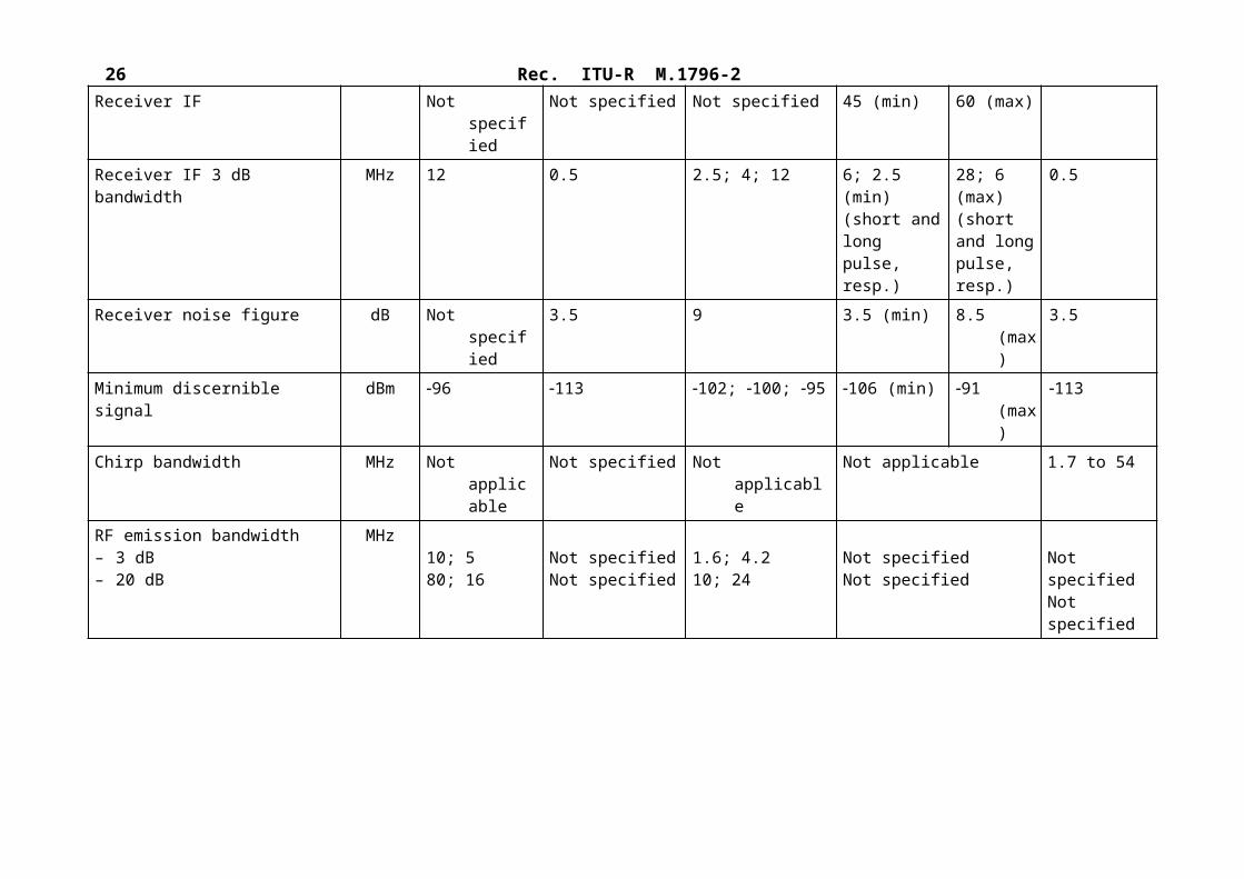
Receiver IF Not specified Not specified Not specified 45 (min) 60 (max)Receiver IF 3 dB bandwidth MHz 12 0.5 2.5; 4; 12 6; 2.5 (min)
(short and long pulse, resp.)
28; 6 (max)(short and long pulse, resp.)
0.5
Receiver noise figure dB Not specified 3.5 9 3.5 (min) 8.5 (max) 3.5Minimum discernible signal dBm 96 113 102; 100; 95 106 (min) 91 (max) 113Chirp bandwidth MHz Not applicable Not specified Not applicable Not applicable 1.7 to 54RF emission bandwidth – 3 dB– 20 dB
MHz10; 580; 16
Not specifiedNot specified
1.6; 4.210; 24
Not specifiedNot specified
Not specifiedNot specified

Rec. ITU-R M.1796-2 17
TABLE 2 (continued)
Characteristics Units System S6 System S7 System S8 System S9Function Maritime radionavigation
radarNavigation and search Maritime radionavigation
radar(6)Maritime radionavigation radar(7)
Platform type Shipborne Shipborne Shipborne ShipborneTuning range MHz 9 380-9 440 9 300-9 500 9 225-9 500 9 225-9 500 9 445 30Modulation Pulse Pulse Pulse PulsePeak power into antenna kW 25 1.5 5 1.5 to 10Pulse width andPulse repetition rate
spps
0.08, 0.2, 0.4, 0.7, and 1.22 200 (0.08 s); 1 800,1 000 and 600 (1.2 s)
0.08, 0.25, and 0.52 250, 1 500 and 750
0.05, 0.18, and 0.53 000 pps at 0.05 s to 1 000 pps at 0.5 s
0.08 (min) at 3 600 pps
1.2 (max) at 375 pps
Maximum duty cycle 0.00072 0.000375 0.0005 0.00045Pulse rise/fall time s 0.010/0.010 0.01/0.05 Not specified Not specifiedOutput device Magnetron Magnetron Magnetron MagnetronAntenna pattern type Fan Fan Fan FanAntenna type End-fed slotted array Centre-fed slotted
waveguideSlotted array Slotted/patch array or horn
Antenna polarization Horizontal Horizontal Horizontal HorizontalAntenna main beam gain dBi 31 23.9 30 22-30
Antenna elevation beamwidth
degrees 20 25 26 24-28
Antenna azimuthal beamwidth
degrees 0.95 6 0.95 1.9-7
Antenna horizontal scan rate
degrees/s 144 144 180 144
Antenna horizontal scan type (continuous, random, sector, etc.)
degrees 360 360 360 360

18 Rec. ITU-R M.1796-2TABLE 2 (continued)
Characteristics Units System S6 System S7 System S8 System S9
Antenna vertical scan rate degrees/s Not applicable Not applicable Not applicable Not applicableAntenna vertical scan type Not applicable Not applicable Not applicable Not applicableAntenna side-lobe (SL) levels (1st SLs and remote SLs)
dBi Not specified +2.9 < 5 within 10; 2 outside 10
22 main beam:3 to 4 within 10;0 to 3 outside 1030 main beam:7 to 10 within 10;–2 to +7 outside 10
Antenna height Mast Mast Mast MastReceiver IF MHz Not specified Not specified 50 45-60Receiver IF 3 dB bandwidth
MHz 15 10 and 3 15-25 2.5-25
Receiver noise figure dB 6 6 6 4 to 8Minimum discernible signal
dBm –97 (noise floor) –102 (noise floor) Not specified Not specified
Total chirp width MHz Not applicable Not applicable Not applicable Not applicableRF emission bandwidth– 3 dB– 20 dB
MHz1443
2055
Not specified Not specified
(3) IMO category – including fishing.(4) Uncompressed pulse, pseudo-random frequency-agile.(5) Frequency sweep rate (sweep/s).(6) River category.(7) Pleasure craft category.

Rec. ITU-R M.1796-2 19
TABLE 2 (continued)
Characteristics Units System S10 System S11 System S12
Function Surveillance radar Marine navigation radar Surveillance radarPlatform type Shipborne Shipborne Vessel and CoastalTuning range MHz 9 225-9 500 9 325-9 460 9 000-9 200 or
9 225-9 500Modulation Pulse compression Pulsed V7N
Fully coherent pulse compression radar using complex pattern of chirps at up to 6 centre frequencies with three different chirp durations
Peak power into antenna kW 0.2 25 0.05-0.1Pulse width andPulse repetition rate
spps
0.08-1001 000-10 000
0.06/0.25/0.5/13 000/2 000/1 000/750
0.150 to 401 000-5 000
Maximum duty cycle 0.2 7.5×10⁻⁴ 0.2Pulse rise/fall time s 0.02 0.015/0.086 Around 0.02Output device Solid state Magnetron (incoherent) Solid stateAntenna pattern type Fan Fan beam Fan beamAntenna type Slotted waveguide Slotted waveguide array Slotted waveguideAntenna polarization Circular/Horizontal Horizontal HorizontalAntenna main beam gain dBi 37 31 ≥ 34Antenna elevation beamwidth degrees 11 25 ≤ 16º @ –3 dB / ≤ 55º @ –20 dB (Typ.)Antenna azimuthal beamwidth degrees 0.4 0.95 ≤ 0.6º @ –3 dBAntenna horizontal scan rate degrees/s 60-288 144 or 240 10-48 RPMAntenna horizontal scan type (continuous, random, sector, etc.)
degrees Continuous or sectors continuous Continuous or sectors

20 Rec. ITU-R M.1796-2
TABLE 2 (continued)
Characteristics Units System S10 System S11 System S12
Antenna vertical scan rate degrees/s Not applicable Not applicable Not applicableAntenna vertical scan type Not applicable Not applicable Not applicableAntenna side-lobe (SL) levels (1st SLs and remote SLs)
dBi 28 < 32/remote SLs < −40 1.5°-5° < 65°-10° < 4> 10° < 1
Antenna height m Normally 30-100 Typically 10-50 m depending on ship’s installation
Installation dependent
Receiver IF 3 dB bandwidth MHz 180 22 or 5 180 (analogue)resolution BW is 12.5 or 25(8)
Receiver noise figure dB 2.5 2.5 2.5Minimum discernible signal dBm –130 130 130 equivalent after pulse compressionTotal chirp width MHz Normally 6 × 35 MHz Not applicable 6 × 35 = 210 (3 dB BW)(9)
RF emission bandwidth 3 dB 20 dB
MHz 240275
9 at (3 dB)66 at (20 dB)For shortest pulse
Depending on profiles setup. Normally the full band is used so the 20 dB BW stays within the frequency band 9 225-9 500 MHz and the 3 dB BW is the combined BW of all centre frequencies used. Default individual chirp 3 dB BW is 35(10)
Dynamic range dBMinimum number of processed pulses
(8) By 180 MHz analogue BW the instantaneous BW that can be handled in the A/D conversion. This “window” can be moved in frequency according to the need.
(9) The term “total chirp width” when regarding frequency spectrum covered is then the combined BW of all used chirps and is then up to 6 × 35 MHz = 210 MHz (3 dB BW).
(10) Up to 6 individual centre frequencies can be used. The normal individual chirp BW (3 dB) is 30-35 MHz. The total RF bandwidth used might be greater than 180 MHz, and is normally the frequency band used (e.g. 9.0-9.2 GHz or 9.225-9.500 GHz).

Rec. ITU-R M.1796-2 21
TABLE 2 (continued)
Characteristics Units System S13
Function Marine navigation radarPlatform type Vessel and CoastalTuning range MHz 9 200-9 500Modulation Continuous wave (CW) pulse for short range
Non-Linear frequency modulated chirp pulse for long range (Chirp bandwidth is 20 MHz)
Peak power into antenna kW 0.17 nominal0.20 peak
Pulse width andPulse repetition rate
spps
0.1, 5 and 33 s wide pulses with pulse repetition intervals of 12, 64 and 365 s and 2267 effective PRF
Maximum duty cycle 13%Pulse rise/fall time s Around 0.02Output device Solid StateAntenna pattern type FanAntenna type Slotted arrayAntenna polarization HorizontalAntenna main beam gain dBi 32.7 or 34.5Antenna elevation beamwidth degrees 25Antenna azimuthal beamwidth degrees <0.7 or <0.45Antenna horizontal scan rate degrees/s 12 or 24 RPMAntenna horizontal scan type (continuous, random, sector, etc.)
degrees Continuous
TABLE 2 (end)

22 Rec. ITU-R M.1796-2Characteristics Units System S13
Antenna vertical scan rate degrees/s Not applicable
Antenna vertical scan type Not applicable
Antenna side-lobe (SL) levels (1st SLs and remote SLs)
dBi 26
Antenna height m Ship size dependent
Receiver IF 3 dB bandwidth MHz 15, 0.1875 and 0.0375Receiver noise figure dB 5.5Minimum discernible signal dBm 125Total chirp width MHz 20RF emission bandwidth 3 dB
20 dB
MHz3 dB: 15 (short range)3 dB: 20 (long range)
20 dB: 18 (short range)20 dB: 22 (long range)
Dynamic range dB 125
Minimum number of processed pulses 32 pulses integrated (12 RPM)16 pulses integrated (24 RPM)

Rec. ITU-R M.1796-2 23
TABLE 3
Characteristics of beacons and ground-based radiodetermination radars operating in the frequency band 8 500-10 680 MHz*
Characteristics Units System G1 System G2 System G3 System G4 System G5
Function Rendez-vous beacon transponder
Rendez-vous beacon transponder
Tracking radar Tracking radar Precision approach and landing radar
Platform type Airborne Ground (manpack) Ground (trailer) Ground (trailer) Ground (trailer)Tuning range MHz 8 800-9 500 9 375 and 9 535 (Rx);
9 310 (Tx)9 370-9 990 10 000-10 500 9 000-9 200
Modulation Single or double pulse
Pulse Frequency-agile pulse CW, FMCW Frequency-agile pulse
Peak power into antenna
kW 0.300 0.020 to 0.040 31 14 120
Pulse width andpulse repetition rate
spps
0.310 to 2 600
0.3 to 0.4Less than 20 000
17 690 to 14 700
Not applicableNot applicable
0.256 000
Maximum duty cycle 0.00078 0.008 0.015 1 0.0015Pulse rise/fall time s 0.1/0.2 0.10/0.15 0.05/0.05 Not applicable 0.02/0.04Output device Magnetron Solid state Travelling wave tube Travelling wave tube Travelling wave tubeAntenna pattern type Omnidirectional Quadrant Pencil Pencil Pencil/fanAntenna type Open-ended
waveguidePrinted-circuit array Phased array
(linear slotted waveguide)
Planar array Planar array of dipoles
Antenna polarization Linear Circular Linear Linear CircularAntenna main beam gain
dBi 8 13 42.2 42.2 40
TABLE 3 (continued)

24 Rec. ITU-R M.1796-2Characteristics Units System G1 System G2 System G3 System G4 System G5
Antenna elevation beamwidth
degrees 18 20; 3 0.81 1 0.7
Antenna azimuthal beamwidth
degrees 360 65; 10 1.74 1 1.1
Antenna horizontal scan rate
degrees/s Not applicable Not applicable Not specified 90 5 to 30
Antenna horizontal scan type (continuous, random, sector, etc.)
Not applicable Not applicable Sector: 45 (phase-scanned)
360 (mechanical) Sector: +23/+15(phase-scanned)
Antenna vertical scan rate degrees/s Not applicable Not applicable Not specified 90 5 to 30Antenna vertical scan type
Not applicable Not applicable Sector: 90 array tilt (frequency-scanned)
Sector: 90 array tilt (mechanical)
Sector: +7/1(frequency-scanned)
Antenna side-lobe (SL) levels (1st SLs and remote SLs)
dBi Not specified 0 (1st SL) Not specified Not specified Not specified
Antenna height Aircraft altitude Ground level Ground level Ground level Ground levelReceiver IF 3 dB bandwidth
MHz 24 40 1 0.52 2.5
Receiver noise figure dB Not specified 13 Not specified 3.4 Not specifiedMinimum discernible signal
dBm 99 65 107 113 98
Chirp bandwidth MHz Not applicable Not applicable Not applicable Not specified Not applicableRF emission bandwidth– 3 dB– 20 dB
MHz2.413.3
4.711.2
0.855.50
Not specifiedNot specified
3.625.0

Rec. ITU-R M.1796-2 25
TABLE 3 (continued)
Characteristics Units System G6 System G7 System G8
Function Airport surveillance/GCA Precision approach radar Airport surface detection equipment (ASDE)
Platform type Ground (mobile) Ground (fixed or transportable) GroundTuning range MHz 9 025 9 000-9 200
(4 frequencies/system)9 000-9 200; pulse-to-pulse agile over 4 frequencies
Modulation Plain and NLFM pulses Plain and NLFM pulse pairs Plain and LFM pulse pairsPeak power into antenna W 310.5 500 70Pulse width and pulse repetition rate
spps
1.2, 30, and 96 12 800, 3 200-6 300 and 2 120
0.65 and 25 pulse-pair3 470, 3 500, 5 200 and 5 300
0.04 and 4.0 (compressed to 0.040)4 096 each, 8192 total
Maximum duty cycle 0.203 0.11 0.017Pulse rise/fall time s Not specified 0.15/0.15 and 0.15/0.15 Short pulse: 0.016/0.018;
Long pulse: 0.082/0.06Output device Solid state Transistors Solid stateAntenna pattern type Fan (csc2) Vertical fan and horizontal fan Inverse csc2
Antenna type Active array + reflector Two phased arrays Passive arrayAntenna polarization Vertical Right-hand circular Right hand circularAntenna main beam gain dBi 37.5 Tx, 37 Rx Vertical fan: 36
Horizontal fan: 3635
Antenna elevation beamwidth degrees 3.5 + csc2 to 20 Vertical fan: 9.0Horizontal fan: 0.63
19
Antenna azimuthal beamwidth degrees 1.05 Vertical fan: 1.04Horizontal fan: 15
0.35
TABLE 3 (continued)

26 Rec. ITU-R M.1796-2Characteristics Units System G6 System G7 System G8
Antenna horizontal scan rate degrees/s 12 Vertical fan: 60, half time (60 scans/min)
360
Antenna horizontal scan type (continuous, random, sector, etc.)
360 30 sector Continuous
Antenna vertical scan rate degrees/s Not applicable Horizontal fan: 20, half time(60 scans/min)
Not applicable
Antenna vertical scan type Not applicable 10° sector Not applicableAntenna side-lobe (SL) levels (1st SLs and remote SLs)
dBi 7.5 average on Tx, 2.9 average on Rx
Vertical fan: 17 Horizontal fan: 18.5
Az plane: +10El plane: +20
Antenna height m Ground level Ground level 30 to 100 m above ground levelReceiver IF 3 dB bandwidth MHz Not specified
0.8 (estimated)40 36
Receiver noise figure dB 5 to 6.5 7.5 5.56Minimum discernible signal dBm Not specified –90 (S/N = 13.5 dB) –96.2Dynamic range dB 65 from noise to 1 dB
compressionNot specified Not specified
Minimum number of processed pulses per CPI
7 6 4-pulse noncoherent integration
Total chirp width MHz Not specified0.8 (estimated)
2 Short pulse: none;Long pulse: 50
RF emission bandwidth– 3 dB– 20 dB
MHz0.8 (estimated)Unknown
1.1 (plain pulse),1.8 (NLFM)5.8 (plain pulse), 3.15 (NLFM)
43.270.3
Interference rejection features Not specified Not specified Local CFAR;Clutter map;2-D spatial filter
TABLE 3 (continued)
Rec. ITU-R M.1796-2 27Characteristics Units System G9
Function Tracking radarPlatform type GroundTuning range MHz 8 700 to 9 500Modulation Linear FM pulsePeak power into antenna kW 150Pulse width andPulse repetition rate
spps
1-15500-15 000
Maximum duty cycle Not specifiedPulse rise/fall time s 0.05Output device TWTAntenna pattern type PencilAntenna type Planar arrayAntenna polarization LinearAntenna main beam gain dBi 38Antenna elevation beamwidth degrees 5Antenna azimuthal beamwidth degrees 5Antenna horizontal scan rate degrees/s 300Antenna horizontal scan type (continuous, random, sector, etc.) ContinuousAntenna vertical scan degrees Not applicable
TABLE 3 (end)

28 Rec. ITU-R M.1796-2Characteristics Units System G9
Antenna vertical scan type RandomAntenna side-lobe (SL) levels (1st SLs and remote SLs) dBi Not specifiedAntenna height M Ground levelReceiver IF 3 dB bandwidth MHz 3Receiver noise floor dBm –105Receive loss dB Not specifiedChirp bandwidth MHz 3RF emission bandwidth– 3 dB– 20 dB
MHz
3
* Radar systems with characteristics similar to those given in Table 2 for maritime radionavigation systems may also be used for ground based aeronautical radars at airports.

Rec. ITU-R M.1796-2 29
TABLE 4
Characteristics of other radars operating in the frequency band 8 500-10 680 MHz
Characteristics Units System G10 System G11 System G12
Function Intrusion detection Intrusion detection Velocity measurementPlatform type Ground Ground GroundTuning range GHz 10.525 10.15-10.65 10.519-10.531Modulation CW CW CWPeak power into antenna W 10 10 0.5Average power into antenna W Not applicable Not applicable Not applicable
Pulse width andpulse repetition rate
spps
Not applicable Not applicable Not applicable
Maximum duty cycle 1 1 1Pulse rise/fall time s Not applicable Not applicable Not applicableAntenna pattern type Parabolic Parabolic Pencil beamAntenna type Parabolic Parabolic Planar arrayAntenna polarization Vertical Vertical VerticalAntenna main beam gain dBi 38 42 21Antenna elevation beamwidth degrees 1.9 2 20Antenna azimuthal beamwidth degrees 1.9 1.2 10Antenna horizontal scan rate Not specified Not specified Not specifiedAntenna horizontal scan type (continuous, random, sector, etc.) Not specified Not specified Not specified
Antenna vertical scan Not specified Not specified Not specifiedAntenna vertical scan type Not specified Not specified Not specified

30 Rec. ITU-R M.1796-2
TABLE 4 (continued)
Characteristics Units System G10 System G11 System G12
Antenna side-lobe (SL) levels (1st
SLs and remote SLs)dBi 28 22 at 3 degrees 9 at 14 degrees
Antenna height Not specified Not specified Not specifiedReceiver IF 3 dB bandwidth MHz Not applicable Not applicable Not applicableSensitivity dBm –100 –152 –136Receive noise figure dB 13 3.6 7Chirp bandwidth MHz Not applicable Not applicable Not applicableRF emission bandwidth– 40 dB
MHz3.2 3.2 3.2

Rec. ITU-R M.1796-2 31
TABLE 4 (continued)
Characteristics Units System G13 System G14 System G15 System G16
Function Track radar Track radar Tracking radar Tracking radarPlatform type Airborne Shipborne Ground (trailer) Ground and Ship borneTuning range GHz 10.5-10.6 10.5-10.6 10.5-10.6 10.5-10.68Modulation CW, FMCW CW, FMCW CW, FMCW LFMPeak power into antenna kW 1.5 13.3 14 70Average power into antenna W – – – 20 000Pulse width andPulse repetition rate
spps
Not applicableNot applicable
Not applicableNot applicable
Not applicableNot applicable
2-155-140 K
Maximum duty cycle 1 1 1 0.28Pulse rise/fall time s Not applicable Not applicable Not applicable .005Antenna pattern type Pencil Pencil Pencil PencilAntenna type Planar array Planar array Planar array Planar arrayAntenna polarization Linear Linear Linear LinearAntenna main beam gain dBi 35.5 43 42.2 46Antenna elevation beamwidth degrees 2.5 1 1 2Antenna azimuthal beamwidth degrees 2.5 1 1 2Antenna horizontal scan rate degrees/s 90 90 90 Not applicableAntenna horizontal scan type (continuous, random, sector, etc.)
Sector: 60 (mechanical) 360 (mechanical) 360 (mechanical) Sector: 90 (mechanical)
Antenna vertical scan degrees/s 90 90 90 Not applicableAntenna vertical scan type Sector: 60 (mechanical) Sector: +83/–30
(mechanical)Sector: 90 array tilt (mechanical)
Sector: +85/–10 (mechanical)

32 Rec. ITU-R M.1796-2TABLE 4 (continued)
Characteristics Units System G13 System G14 System G15 System G16
Antenna side-lobe (SL) levels (1st SLs and remote SLs)
dBi Not specified 23 (1st SL) Not specified Not specified
Antenna height Aircraft altitude Mast/deck mount Ground level Mast/deck mountReceiver IF 3 dB bandwidth MHz 0.48 0.5 0.52 10Sensitivity dBm – 113 113 112Noise power dBm – – –Receive noise figure dB 3.6 3.5 3.4 4.5Chirp bandwidth MHz Not specified Not specified Not specified 10RF emission bandwidth– 3 dB– 20 dB
MHzNot specifiedNot specified
Not specifiedNot specified
Not specifiedNot specified
5.511

Rec. ITU-R M.1796-2 33
TABLE 4 (continued)
Characteristics Units System G17 System G18 System G19
Function Multipurpose Surveillance, scanning, Tracking
Airport surface detection equipment
Airport surface detection equipment
Platform type Ground (trailer) Ground GroundTuning range MHz 9 200-9 900 9 0009 200; pulse-to-pulse agile
over 16 frequencies predefined hopping
9 000-9 200; pulse-to-pulse agileover 4 frequencies predefined hopping
Modulation Adaptive Pulse, FM Plain and LFM pulse pairs Two LFM pulses define a pulse pairPeak power into antenna W 30-10 000 170 50Pulse width and pulse repetition rate
spps
0.15-30 adaptive1 000-20 000 adaptive
0.040 and 4.0 (compressed to 0.040) 16 384 each
10.0 and 0.15 at 7 500 (both compressed to 0.040); system maximum average 15 000
Maximum duty cycle 0.60 (pulse) 1 (FM) 0.07 0.15Pulse rise/fall time s Not specified Short pulse: 0.016/0.023
Long pulse: 0.038/0.056Short pulse: 0.020/0.020Long pulse: 0.020/0.020
Output device Solid state Solid state Solid stateAntenna pattern type Digital beamforming Inverse csc2 Inverse csc2
Antenna type Active planar array Passive array Slotted waveguideAntenna polarization Linear/circular Right hand circular Right-hand circularAntenna main beam gain dBi 36-42 37.6 37.6Antenna elevation beamwidth
degrees 4 @ 36 dBi2 @ 42 dBi
9.91 9.91
Antenna azimuthal beamwidth
degrees 2.5 @ 36 dBi1.3 @ 42 dBi
0.37 0.37

34 Rec. ITU-R M.1796-2
TABLE 4 (end)
Characteristics Units System G17 System G18 System G19
Antenna horizontal scan rate degrees/s Not applicable 360 360Antenna horizontal scan type (continuous, random, sector, etc.)
± 60° electronic scanN*360° mechanical
Continuous Continuous
Antenna vertical scan rate degrees/s Not applicable Not applicable Not applicableAntenna vertical scan type ±40° electronic Not applicable Not applicableAntenna side-lobe (SL) levels (1st SLs and remote SLs)
dBi Depend on beamforming 9.15 9.15
Antenna height ~ 10 m 10 to 100 m above ground 10 to 100 m above groundReceiver IF 3 dB bandwidth MHz Not specified 50 180Receiver noise figure dB 6 5.25 5.0Minimum discernible signal dBm 122 –102 –115Dynamic range (dB) dB Not specified Not specified Not specifiedMinimum number of processed pulses per CPI
Not specified Not specified Not specified
Total chirp width MHz Not specified Short pulse: noneLong pulse: 50
Short pulse: 35Long pulse: 35
RF emission bandwidth– 3 dB– 20 dB
MHzAdaptiveAdaptive
5059
3542

Rec. ITU-R M.1796-2 35
2.1 Transmitters
The radars operating in the frequency band 8 500-10 680 MHz use a variety of modulations including unmodulated pulses, continuous wave (CW), frequency-modulated (chirped) pulses, phase-coded pulses and some new radars with digital signal processing may use adaptive modulation with different modulations schemes, variable pulse duration and repetition rate. Crossed-field, linear-beam, and solid-state output devices are used in the final stages of the transmitters. The trend in new radar systems is toward linear-beam and solid-state output devices due to the requirements of Doppler signal processing. Also, the radars deploying solid-state output devices have lower transmitter peak output power and higher pulse duty cycles. In four cases (Systems A4, S2, S5, and G4), the duty cycle is 100%, with the high-power CW radiolocation radars all operating only above 10 GHz. There is also a trend towards frequency-agile type radar systems that will suppress or reduce interference, much as is done in some communications systems. Frequency agility is also sometimes used to avoid range-ambiguous clutter return. The random (or pseudo-random) transmissions on a single carrier frequency can occur throughout a coherent processing interval or even a full antenna-beam position or dwell, during which many pulses are transmitted, or for only a single pulse. These alternatives are similar to “slow frequency hopping” and “fast frequency hopping” in a communication system. These important aspects of radar systems should be taken into account in compatibility studies.
Typical transmitter RF emission (3 dB) bandwidths of radars operating in the frequency band 8 500-10 680 MHz from 45 kHz to 637 MHz. Transmitter peak output powers range from 1 mW (0 dBm) for solid-state transmitters to 220 kW (83.4 dBm) for high-power radars using crossed-field devices (magnetron).
The characteristics of unwanted emissions are not addressed in this Recommendation.
2.2 Receivers
The newer-generation radar systems use digital signal processing after detection for range, azimuth and Doppler processing. Generally, the signal processing includes techniques that are used to enhance the detection of desired targets and to produce target symbols on the display. The signal-processing techniques used for the enhancement and identification of desired targets also provide some suppression of low-duty-cycle (less than 5%) pulsed interference that is asynchronous with the desired signal.
The signal processing in the newer generation of radars uses chirped and phase-coded pulses to produce a processing gain for the desired signal and may also provide suppression of undesired signals.
Some of the newer low-power solid-state radars use high-duty-cycle multichannel signal processing to enhance the desired signal returns. Some radar receivers have the capability to identify RF channels that have low levels of undesired signals and command the transmitter to transmit on those RF channels.
Newer radars often use a broadband input stage with the full span of the possible frequency range. Even the IF-filters are designed with relatively high bandwidth. This enables features like frequency-hopping and adaptive modulation with variable bandwidth. The final processing including adaptive filtering is done in the baseband signal processing.
2.3 Antennas
A variety of types of antennas are used on radars operating in the frequency band 8 500-10 680 MHz. Antennas in this frequency band are generally of convenient size and thus are of interest for applications where mobility and light weight are important and long range is not.

36 Rec. ITU-R M.1796-2
Many types of radar in the frequency band 8 500-10 680 MHz operate in a variety of modes, including search and navigation (weather observation) modes. The antennas for such radars usually scan through 360° in the horizontal plane.
Newest developments in radar technology (e.g. Low temperature co-fired ceramics, shrinking of RF-modules, increased processing power) enable a baseband signal processing of each single antenna element of a phased array antenna.
The single elements of an active phased array are only slightly directive and the beam is formed by using a large number of single elements with a variable phase shift. As a consequence, the mechanisms of interference and interference rejection are different from legacy antennas (e.g. with parabolic reflectors).
These radars do have the capability to perform different radar tasks (e.g. tracking and scanning and tracking of multiple targets) simultaneously. A scanning line by line or circles of a pencil beam is replaced by signal processing with adaptive tracking and scanning.
Transmitter: Transmission of the signal is done by a very fast switchable beam.Reception: Depending on the signal processing applied the reception can be done in principle in
two ways.1) A digitally formed beam can be synchronized with the transmitter. 2) It is additionally possible to receive and detect several signals from other transmitters (e.g.
radars in other airplanes) simultaneously with a multiple beam antenna (explanation see below).
In consequence, this means that mechanisms for decoupling are different to radars with conventional antennas.
Multiple beam antennas (see Fig. 1)
Each antenna element provides a baseband signal, which can be weighted by phase and amplitude (Wi,n) with the weighted baseband signals (Wj,n of other elements). This is represented by a steering vector for one direction. The output of this mathematical operation is the signal received in a specific direction θn. Combining different steering vectors in a steering matrix with a number N of different steering vectors, the antenna is able to receive simultaneously in different directions θ1 to θN. It should be mentioned that modern radar processors are able to perform more than one TFLOPS (1012 Floating point Operations Per Second), which enables the implementation even for larger arrays. Possible implementations are for example a FFT-beamforming or space time signal processing.

Rec. ITU-R M.1796-2 37
FIGURE 1Multiple beam antenna
Other radars in the frequency band are more specialized and limit scanning to a fixed sector. Most radars in the frequency band 8 500-10 680 MHz use mechanical scanning, however some newer-generation radars use electronically scanned array antennas as described. Horizontal, vertical, and circular polarizations are used. Typical antenna heights for ground-based and shipborne radars are 8 m and 30 m above surface level, respectively, although many maritime radionavigation radars are lower than 30 m.
3 Additional technical and operational characteristics of shipborne radionavigation systems in the frequency band 9 200-9 500 MHz
In global terms, a clear distinction can be made between radars that conform to the requirements of the International Maritime Organization (IMO) (including those used on fishing vessels), those that are used for inland navigation (rivers) and those fitted on a voluntary basis in pleasure crafts, for safety purposes.
In Table 5 are the comparisons of transmitter power and numbers of radars for the three categories above.
TABLE 5
Categories of shipborne radionavigation radars
Radar category Peak power (kW) Global total
IMO and fishing 75 > 300 000River < 10 < 20 000
Pleasure < 5 > 2 000 000

38 Rec. ITU-R M.1796-2
Almost all the radars used aboard river and pleasure craft operate in the frequency band 9 200-9 500 MHz. Most of the IMO and fishing-craft radars also operate in the same frequency band, although substantial numbers of IMO radars operate in the frequency band 2 900-3 100 MHz.
The radar characteristics that affect the efficient use of the spectrum, including protection criteria, are those associated with the radar antenna and transmitter/receiver. Most of the maritime radars use slotted array antennas, however, some of the pleasure craft radars employ patch arrays or horns.
4 Additional information relevant to maritime radionavigation radars
4.1 Performance requirements and interference effects
Radionavigation systems may fail to meet their performance requirements if undesired signals inflict excessive amounts of various types of interference degradation. Dependent upon the specific interacting systems and the operational scenarios, those types may include:– diffuse effects, e.g. desensitization or reduction of detection range, target drop-outs and
reduction of update rate;– discrete effects, e.g. detected interference, increase of false-alarm rate.
Associated with these types of degradation, the protection criteria are associated with threshold values of parameters, e.g. for a collision avoidance system:– tolerable reduction of detection range and associated desensitization;– tolerable missed-scan rate;– tolerable maximum false-alarm rate;– tolerable loss of real targets;– tolerable errors in estimation of target position.
The operational requirement for maritime radars is a function of the operational scenario. This is related to the distance from shore and sea obstacles. In simplistic terms this can be described as oceanic, coastal or harbour/port scenarios.
The IMO has adopted a revision to the operational performance standards for maritime radar1. The IMO revision, for the first time, gives recognition to the possibility of interference from other radio services.
Most importantly, the international maritime authorities have stated, without reservation, in their recent update of the IMO Safety of Life at Sea Convention, that radar remains a primary sensor for the avoidance of collisions.
This statement should be viewed in the context of the mandatory fitting of Automatic Identification Systems (AIS) to some classes of ships. These systems rely upon external references, e.g. GPS, for the verification of relative position indication in terms of collision avoidance scenarios.
However, the fitting of such systems can never take account of many maritime objects, e.g. icebergs, floating debris, wrecks, etc. that are not fitted with AIS. These objects are potential causes of collision with ships, and need to be detected by ship radars. Radar will therefore remain the primary system for collision avoidance for the foreseeable future.
1 IMO Resolution MSC.192 (79), Adoption of the revised performance standards for radar equipment, adopted on 10 December 2004.

Rec. ITU-R M.1796-2 39
Among other radar targets, the IMO standards mention the need for radar to detect small floating and fixed hazards and fixed aids to navigation. They require that various specified targets be detected on at least eight out of ten scans, with a false-alarm rate of 10−4. The specified targets include small vessels with a radar reflector meeting IMO performance standards, as well as navigation buoys and small vessels with no radar reflector, each at particular ranges2. The standards also require range and bearing accuracy to be within 30 m and 1, respectively. They call for means to be provided for adequate reduction of interference from other radars. They require capability for displaying resolution of two point targets on the same bearing but separated by 40 m in range and resolution of two point targets separated in bearing by 2.5. They call further for minimizing the possibility of tracking one target in place of another (“target swap”) and an alarm when a tracked target is lost, all of which also bears on target resolution and position errors that can be exacerbated by interference.
4.2 Special description for New Marine Navigation Radar S13
The transmitter of Radar S13 is solid state that used chirp waveform and conforms to the design requirements of IMO minimum performance requirements IEC 62388 (new radar standard – July 2008). The radar is capable of operating in a number of modes with each mode optimized for a particular operational requirement. The modes of operations are river/canal surveillance, estuary surveillance, costal surveillance, low power mode, and for Helicopter guidance for search and rescue. Some of the important features of radar S13 are:– Solid state transmitter that use transistors instead of a magnetron,– Coherent transmitter and receiver,– Non-Linear frequency modulation and Pulse compression are used to recover range
resolution,– Target presence is determined using digital signal processing employing Doppler
processing and variable threshold constant-false-alarm-rate (CFAR),– Antenna size is 3.7 or 5.5 m long with a horizontal beamwidth of less than 0.7 degrees
(antenna width =3.7 m) or less than 0.45 degrees (antenna width =5.5 m),– Low voltage operation,– Pulse repetition frequency discrimination. The radar uses 3 Pulse Transmission Frames
with short pulses that enable 30 m minimum range, medium and long pulses provide detection performance with effective pulse repetition frequency (PRF) of 2 268 Hz,
– The radar utilizes multiple frames on Target per antenna beamwidth,– Utilizes Doppler processing techniques,– Peak power is 200 watts with 170 watts minimum power at 13% duty cycle,– Controlled RF Spectrum that is ITU compliant and selection of 12 transmit RF frequencies
providing frequency diversity to improve target detection,– Radar waveform are digitally generated,– The signal processing provides protection from multiple time around echoes,– Provides improved detection and rain and sea clutter rejection performance,– Provides energy for detection and meets minimum range constraint of IMO,– The radar range cell size is maintained over the entire instrumented range,– Low power mode is available that reduces transmit power by 7 dB.
2 IMO revised performance standards for radar reflectors (Resolution MSC.164(78)).

40 Rec. ITU-R M.1796-2
5 Additional information relevant to unmanned aircraft detect and avoid radars
An emerging class of airborne radars, known as Detect-And-Avoid (DAA) radars, is being developed for the purpose of enhancing flight safety by providing warnings of potential collisions or conflicts with non-cooperative aircraft. (In this context “non-cooperative” aircraft are aircraft that are not equipped with an Air Traffic Control Radar Beacon System (ATCRBS) transponder, Automatic Dependent Surveillance-Broadcast (ADS-B) system, Traffic alert and Collision Avoidance System (TCAS) or Airborne Collision Avoidance System (ACAS).) The mission of this class of airborne radars encompasses several partially-overlapping functions referred to as collision avoidance, conflict avoidance, self-separation, safe separation, sense-and-avoid and due regard. This class of radars is of particular interest in Unmanned Aircraft (UA) applications where there is no onboard pilot to provide the safety-of-flight function visually.
Detect-and-avoid radars must track all potentially threatening aircraft (called “intruders”) in their field of regard while simultaneously searching for new threats. Since more than one intruder will frequently be in the radar’s field of regard, a multi-target tracker is required. This requires either fairly rapid track-while-scan operation, or alternatively, interleaved search and track functions in a mode called “search while track” in which the track updates are scheduled as they are required. This type of operation requires beam agility beyond the capability of a mechanically scanned antenna. For this reason, all airborne DAA radars currently under development use either electronically scanned antennas or beamforming techniques to provide the required search and track functions.
The range required for detection and tracking depends on the amount of warning time required. This in turn depends on the speed of the host platform (called the “ownship”), the speed of potential threats, the ownship’s maneuvering capability, the type of avoidance maneuver (e.g. lateral vs. vertical) and delays in initiating and executing the avoidance maneuver. A relatively fast UA with limited maneuverability would require a sensor with a greater range than a slower, more maneuverable UA. The range at which a threat warning must be issued is typically 2.5-20 km depending on the host platform characteristics, the intruder characteristics, the required miss distance and the measurement errors. A target track must be established at a somewhat greater range in order to provide this warning capability.
The 8 500-10 500 MHz frequency range is of interest for this class of radars because it provides a good compromise between tracking accuracy and the ability to operate in light-to-moderate rain. Although higher frequencies would provide better angle measurement accuracy for a given antenna size, rain attenuation increases much more rapidly with increasing frequency than the improvement in angle measurement accuracy. Lower frequencies would greatly reduce the effects of rain but would require antenna apertures possibly larger than the host vehicle could accommodate. Of particular interest in this frequency range are two sub-bands (8 750-8 850 MHz and 9 300-9 500 MHz) that have been identified in Report ITU-R M.2204 as suitable for this type of application and are allocated to aeronautical radionavigation services (ARNS).
Other characteristics of DAA radars are enumerated below.– Two or three electronically scanned antenna faces are typically used to provide
±110 degrees of azimuth coverage.– Medium pulse repetition frequency (MPRF) and/or high pulse repetition frequency (HPRF)
waveforms with PRFs in the 5-60 kHz range are used to provide clutter rejection in look-down encounters. Low pulse repetition frequency (LPRF) waveforms with PRFs of roughly 1-2 kHz may be used in look-up encounters to provide range-unambiguous performance.
– Solid-state RF power amplification is used, with transmit duty factors typically in the range of 4-20%.

Rec. ITU-R M.1796-2 41
– Pulse compression using intrapulse phase coding (e.g. Barker codes, pseudo-noise codes, Lewis-Kretschmer “P” codes, etc.) or intrapulse linear frequency modulation (LFM) is often employed to reduce the range cell size in order to improve the target-to-clutter ratio while maintaining a high duty factor.
– Digital signal processing provides Doppler filter bandwidths of 50-500 Hz enabling target discrimination based on velocity and facilitating clutter rejection.
– Monopulse angle measurement permits accurate angle tracking on fluctuating target returns.
– Frequency agility may be used to decorrelate target fluctuations, improving the probability of detection and improving the track quality.
– A guard antenna (also called a sidelobe blanker) may be employed to mitigate the effects of ground clutter and interference received through the antenna sidelobes.
Characteristics of example DAA radar are presented in Table 1 (System A13).
6 Future radiodetermination systems
In broad outline, radiodetermination radars that might be developed in the future to operate in the frequency band 8 500-10 680 MHz are likely to resemble the existing radars described here. In addition to providing the potential for high-resolution volume sampling throughout the entire troposphere, the network of distributed Doppler weather radars will be designed for efficient utilization by employing low-power solid-state operation. Other technical parameters, such as a 1 metre antenna diameter and low duty cycle modes of operation are consistent with current radiodetermination radars operating in the frequency band 8 500-10 680 MHz. Future radiodetermination radars are also likely to have at least as much flexibility as the radars already described, including the capacity to operate differently in different azimuth and elevation sectors.
It is reasonable to expect that some future designs may strive for a capability to operate in a wide frequency band extending at least to the frequency band limits used in this consideration.
Future radiodetermination radars are likely to have electronically steerable beam antennas. Current technology makes phase steering a practical and attractive alternative to frequency steering, and numerous radiodetermination radars developed in recent years for use in other frequency bands have employed phase steering in both azimuth and elevation. Unlike frequency-steered radars (e.g. Systems 15 and 17), new phased-array radars can steer any fundamental frequency in the radar’s operating frequency band to any arbitrary azimuth and elevation within its angular coverage area. Among other advantages, this would facilitate electromagnetic compatibility in many circumstances.
Some future radiodetermination radars are expected to have average-power capabilities at least as high as those of the radars described herein. However, it is reasonable to expect that designers of future radars will strive to reduce wideband noise emissions below those of the existing radars that employ magnetrons or crossed-field amplifiers. Such noise reduction is expected to be achieved by the use of solid-state transmitter/antenna systems. In that case, the transmitted pulses would be longer in duration and the transmit duty cycles would be substantially higher than those of current tube-type radar transmitters.

42 Rec. ITU-R M.1796-2
Annex 2
Protection criteria for radars
1 Protection criteria
1.1 Continuous noise-like interference
Radars are affected in fundamentally different ways by unwanted signals of different forms, and an especially sharp difference prevails between the effects of continuous noise-like energy and those of pulses. Continuous-wave interference of a noise-like type inflicts a desensitizing effect on radiodetermination radars, and that effect is predictably related to its intensity. Within any azimuth sectors in which such interference arrives, its power-spectral density can, to a reasonable approximation, simply be added to the power-spectral density of the radar-system thermal noise. If the power of radar-system noise in the absence of interference is denoted by N and that of noise-like interference by I, the resultant effective-noise power becomes simply I + N.
Given that, the radar protection criteria traditionally established within ITU-R are based on the penalties incurred to maintain the target-return signal-to-noise ratio in the presence of the interference, requiring that the target-return power be raised in proportion to the increase of noise power from N to I + N. That can only be done by accepting shorter maximum ranges on given targets, sacrificing observation of small targets, or modifying the radar to give it a higher transmitter power or power-aperture product. (In modern radars, receiving-system noise is usually already near an irreducible minimum and nearly optimum signal processing is becoming commonplace.)
These penalties vary depending on the radar’s function and the nature of its targets. For most radars, an increase in the effective noise level of about 1 dB would inflict the maximum tolerable degradation on performance. In the case of a discrete target having a given average or median RCS, that increase would reduce the detection range by about 6% regardless of any RCS fluctuation characteristics that target might have. This effect results from the fact that the achievable free-space range is proportional to the 4th root of the resultant signal-to-noise power ratio (SNR), from the most familiar form of the radar range equation. A 1 dB increase of effective noise power is a factor of 1.26 in power, so it would, if uncompensated, require the free-space range from a given discrete target to be reduced by a factor of 1/(1.261/4), or 1/1.06; i.e. a range capability reduction of about 6%. In the range equation, the SNR is also directly proportional to transmitter power, to power-aperture product (for a surveillance radar), and to target radar cross section. Alternatively, therefore, the 1 dB increase of effective noise power could be compensated by forgoing detection of targets except those having an average radar cross section 1.26 times as large as the minimum-size target that could be detected in the interference-free regime or by increasing the radar transmitter power or its power-aperture product by 26%. Any of these alternatives is at the limit of acceptability in most radar missions, and the system modifications would be costly, impractical, or impossible, especially in mobile radars. For discrete targets, those performance penalties hold for any given probability of detection and false-alarm rate and any target fluctuation characteristics.
Airborne weather-avoidance and weather-observation radars differ from discrete-target radars in having extended targets, typically precipitation, that often fills the entire radar beam (which is typically quite narrow). In the corresponding form of the radar range equation, SNR is inversely proportional to the inverse square of range rather than to its inverse 4th power. For a weather radar observing beam-filling rain, the range reduction for a given precision of rainfall-rate estimation would be the square root of the 1 dB factor; i.e. (1.26)1/2, which equals 1.12. Thus there is a 12%

Rec. ITU-R M.1796-2 43
loss of range capability in the presence of such interference, that also corresponds to a 21% loss of area coverage. Alternatively, for a given range, the interference would raise (i.e. degrade) the minimum measurable weather reflectivity by about 26%, again without regard to weather reflectivity fluctuation characteristics.
Synthetic-aperture imaging radars (SARs) perform coherent integration of return pulses over the time required for the antenna beam RF traverse each pixel in the observed scene by virtue of the radar platform’s motion. Since the width of the beam’s illumination on the ground is directly proportional to the range (typically proportional to the altitude of the radar platform and also increasing with the swath angle), the number of pulses available for integration, and hence the integration processing gain relative to noise, is also proportional to the range. To the extent that design flexibility permits, the output (processed) SNR is therefore modified from the proportionality to the inverse-4th-power of range that prevails with a discrete target observed by a real-aperture radar to a proportionality to the inverse 3rd power of range. Consequently, a 1 dB increase of effective noise power; i.e. the increase by a factor of 1.26 in power, would require that the range of a SAR from given terrain to be imaged be reduced by a factor of 1/(1.261/3), or 1/1.077; i.e. a loss of 7.7%. Provided that operational restrictions permit such a range reduction, that would in turn inflict a corresponding reduction in the rate at which imaging data can be gathered. This again is at the limit of acceptability. Another option would be to raise the average power of the SAR transmitter by 26%, which is likewise at the limit of acceptability.
1.1.1 Aggregation of interference contributions
The 1 dB increase referred to throughout the above discussions corresponds to an (I + N)/N ratio of 1.26, or an I/N ratio of about −6 dB. This represents the tolerable aggregate effect of all interferers. It applies for reception via the radar’s main beam as well as for simultaneous reception via side lobes. The tolerable I/N ratio for an individual noise-like interferer therefore depends on the number of interferers and their geometry and should be assessed in the analysis of a given scenario. This is a consequence of the fact that almost all the radars in this band serve event-driven missions, observe non-cooperative targets, and do not have the benefit of redundancy, including the re-transmission of packets that is becoming used more and more in communications technologies. Basically, sensing, including radar, is a fundamentally different use of the RF spectrum than is communications, and the same interference-protection rules are not appropriate for both.
1.2 Pulsed interference
The effect of pulsed interference is more difficult to quantify and is strongly dependent on receiver-processor design and mode of system operation. In particular, the differential processing gains for valid-target return (which is synchronously pulsed) and interference pulses (which are usually asynchronous) often have important effects on the impact of given levels of pulsed interference. Several different forms of performance degradation can be inflicted by such interference. Assessing it will be an objective for analyses and/or testing of interactions between specific radar types. In general, numerous features of radars of the types described herein can be expected to help suppress low-duty-cycle pulsed interference, especially from a few isolated sources. Techniques for suppression of low-duty-cycle pulsed interference are contained in Recommendation ITU-R M.1372 – Efficient use of the radio spectrum by radar stations in the radiodetermination service.
2 Shipborne radionavigation radars protection criteria
There is as yet no international agreement on the protection criteria required for radars currently installed on ships for the scenarios identified above. However, Recommendation ITU-R M.1461 provides a generic interference/noise level of −6 dB.

44 Rec. ITU-R M.1796-2
The IMO has developed a revision to the operational performance standards for shipborne radar and this revision takes account of the recent ITU requirements for unwanted emissions. The IMO revision, for the first time, gives recognition to the possibility of interference from other radio services, and includes new requirements with respect to the detection of specific targets in terms of RCS (fluctuating) and required range, as a function of radar frequency band. The detection of a target is based upon an indication of it in at least eight out of ten scans and a probability of false alarm of 10−4. These detection requirements are specified in the absence of sea clutter, precipitation and evaporation duct, with an antenna height of 15 m above sea level.
Most importantly, the international maritime authorities have stated, without reservation, in their recent update of the IMO Safety of Life at Sea Convention , that radar remains a primary sensor for the avoidance of collisions.
This statement should be viewed in the context of the mandatory fitting of AIS only to those vessels listed under IMO carriage requirements. These systems rely upon external references, e.g. GPS, for the verification of relative position indication in terms of collision avoidance scenarios.
However, the fitting of such systems can never take account of many maritime objects, e.g. icebergs, floating debris, wrecks, and other vessels, that are not fitted with AIS. These objects are potential causes of collision with ships, and need to be detected by ship radars. Radar will therefore remain the primary system for collision avoidance for the foreseeable future.
Intensive discussion with maritime authorities, including users, has resulted in an operational requirement that during all maritime voyages no interference that can be controlled by regulation is acceptable.
In the meantime, the approach has been to carry out trials and determine what current shipborne radars can accept in terms of interference to noise ratios (I/N) as a function of probability of detection (see Annex 3).
Annex 3
Results of interference trials
1 Interference to noise (I/N) radar trials
Prior to adoption of the revised IMO standards, radar trials were carried out in the United States of America and the United Kingdom to determine the vulnerability of current maritime radars to various forms of interference.
The trials used radars operating in the frequency bands 2 900-3 100 and 9 200-9 500 MHz. Only the trials in the frequency band 9 200-9 500 MHz are discussed herein. The results of the trials are presented as probability of detection as a function of I/N with respect to each type of interference source.

Rec. ITU-R M.1796-2 45
It should be noted that there are no ITU or other internationally agreed receiver specifications for maritime radars, and therefore it is not surprising that there is a wide range of receiver characteristics operating in this operational environment. The trials results reflect this range, and indicate both the continuous degradation of probability of detection as the level of interference increases and also a “cut off” at which the receiver is no longer able to accept the specific level of interference.
Such differences are real and exist in current operational radars.
1.1 Characteristics of specific radars under test
Both of the radars, referred to as radars D and E, are IMO category radars. No pleasure-craft radars were tested. Nominal values for the principal parameters of the radars were obtained from regulatory type-approval documents, sales brochures, and technical manuals. Radar E uses a logarithmic amplifier/detector in its receiver design, while Radar D use a logarithmic amplifier followed by a separate video detector. For all of the radars, the sensitivity-time-control (STC) and fast-time-constant (FTC) were not activated for the tests.
The characteristics of radars D and E are presented below in Tables 6 and 7.
TABLE 6
Radar D parameters
Parameter Units ValueFrequency MHz 9 410 ± 10Pulse power kW 30Range nmi 0.125-1.5 3-24 48 96Pulse width µs 0.070 0.175 0.85 1.0PRF Hz 3 100 1 550 775 390IF bandwidth MHz 22 22 6 6Spurious response rejection dB UnknownSystem noise figure dB 5.5RF bandwidth MHz UnknownAntenna scan rate rpm 24/48Antenna horizontal beamwidth degrees 1.2Antenna vertical beamwidth degrees 25Polarization Horizontal

46 Rec. ITU-R M.1796-2
TABLE 7
Radar E parameters
Parameter Units Value
Frequency MHz 9 410 ± 10Pulse power kW 30Range nmi 0.125-3 6-24 48-96Pulse width µs 0.050 0.25 0.80PRF Hz 1 800 785IF bandwidth MHz 20 20 3Spurious response rejection dB UnknownSystem noise figure dB 4RF bandwidth MHz UnknownAntenna scan rate rpm 25/48Antenna scan time s 2.4/1.25Antenna horizontal beamwidth degrees 2.0Antenna vertical beamwidth degrees 30.0Polarization Horizontal
1.2 Radar receiver interference suppression features
Both of the radars employed circuitry and signal processing to mitigate interference from other co-located radars. Radars D and E use pulse-to-pulse and scan-to-scan correlators to mitigate interference from other radars. However, they do not have CFAR processing. A description of these mitigation techniques is described in Recommendation ITU-R M.1372.
1.3 Interfering signals and targets
The interfering signals included pulses and digital mobile telephony. The pulse source simulated a radiolocation input. Pulse widths of 1 μs and 2 μs were used, with PRFs equivalent to duty cycles of 0.1% and 1%. The digital mobile telephony source simulated two generic CDMA signals one with a bandwidth of 5 MHz and one with a bandwidth of 1.25 MHz.
The emissions were on-tuned with the operating frequency and gated to occur with the simulated targets. The emission spectra of the CDMA interfering signals are shown below in Fig. 2.

Rec. ITU-R M.1796-2 47
FIGURE 2Generic CDMA signals
1.4 Non-fluctuating target generation
A combination of arbitrary waveform signal generators, RF signal generators, discrete circuitry, a laptop PC and other RF components (cables, couplers, combiners, etc.) were used to generate ten equally spaced targets along a 3 nautical mile (~ 5.6 km) radial that had the same RF power level. The power level of the simulated targets was adjusted till the target probability of detection was about 90%. The ten target pulses triggered by each radar trigger all occur within the return time of one of the radar’s short-range scales, i.e. “one sweep”. Consequently, the pulses simulate ten targets along a radial; i.e. a single bearing. For adjustment of the display settings, the RF power of the target generator was set to a level so that all ten targets were visible along the radial on the PPI display with the radar’s video controls set to positions representative of normal operation. Baseline values for the software functions that controlled the target and background brilliance, hue, and contrast settings were found through experimentation by test personnel and with the assistance of the manufacturers and with professional mariners who were experienced with operating these types of radars on ships of various sizes. Once these values were determined, they were used throughout the test program for that radar.
1.5 Test results
1.5.1 Radar D
For Radar D it was possible to observe the effect that the unwanted signals had on individual targets. For each unwanted signal, it was possible to count the decrease in the number of targets that were visible on the PPI as the I/N level was increased. Target counts were made at each I/N level for each type of interference. A baseline target probability of detection, Pd, count was performed before the beginning of each test. The results of the tests on Radar D are shown below in Fig. 3, which shows the target Pd versus the I/N level for each type of interference. The baseline Pd in Fig. 3 is 0.92 with the 1-sigma error bars 0.016 above and below that value. Note that each point in Fig. 3 represents a total of 500 desired targets.

48 Rec. ITU-R M.1796-2
FIGURE 3Radar D probability of detection curves
Figure 3 shows that, except for the case of the pulsed interference, the target Pd was reduced below the baseline Pd used in these tests minus the standard deviation for I/N values above −12 dB for the unwanted CDMA signal.
1.5.2 Radar E
For Radar E it was difficult to count the decrease in target Pd as the interference was injected into the radar’s receiver. The interference caused all of the targets to fade at the same rate no matter where they were in the string of targets. It was not possible to make individual targets “disappear” as the interference power was increased and count the number of lost targets in order to calculate the Pd. Therefore, the data taken for Radar E reflects whether or not the appearance of all the targets was affected at each I/N level for each type of interference. The data for Radar E is summarized below in Table 8.

Rec. ITU-R M.1796-2 49
TABLE 8
Radar E with gated CDMA interference
I/N ratio (dB) 5 MHz CDMA 1.25 MHz CDMA 2000
–12 No effect No effect–10 No effect No effect–9 No effect No effect–6 Targets dimmed Targets dimmed–3 Targets dimmed Targets dimmed0 Targets not visible Targets not visible3 Targets not visible Targets not visible6 Targets not visible Targets not visible
The data in Table 8 show that the unwanted CDMA signals affected the visibility of the targets for Radar E on its PPI at an I/N level of –6 dB. At that level the brightness of the targets on the PPI was noticeably dimmed from their baseline state. At I/N levels of 0 dB and above, the targets had dimmed so much that they were no longer visible on the PPI.
For Radar E, the gated 2.0 and 1.0 μs pulsed interference with duty cycles of 0.1 and 1.0% did not affect the visibility of the targets on the PPI at the highest I/N level, which was 40 dB.
1.6 Summary of trials results
Radar trials were performed to determine for specific radars and interference sources an I/N level for which there is “no effect” from the interference (i.e. the radar is operating at its baseline condition). Unprocessed radar returns commonly known as “blips” or “raw video” were observed and/or counted as targets in these tests.
This “no effect” level is qualified as relative to a 90% probability of a single-scan detection and is summarized below in terms of I/N for each radar and interference source. The results are summarized in Table 9. Determining the acceptable amount of interference for these types of radars can be somewhat subjective due to the eyesight and experience of the radar operator looking at the PPI counting targets and grading the brightness of the targets themselves. However, due to the radar’s design, there is no other way for these tests to be performed other than for the operator/tester to observe the targets on the radar’s PPI.
TABLE 9
Summary of results
Interference source RadarD
RadarE
Pulsed 0.1 +40 +40Pulsed 1.0 +40 +401.25 MHz CDMA 2000 –10 –95 MHz CDMA –12 –9

50 Rec. ITU-R M.1796-2
It should be noted that there are other effects from interference that reduce the operational effectiveness of a radar. An example is the creation of “false targets”. The maritime radars tested do not generally contain CFAR processing.
The results of these tests show that when the emissions of devices using digital modulations are directed towards a radar of the type tested herein exceed an I/N ratio of −6 dB, some of the radars started to have dimmed targets, lost targets, or generate false targets. For other radars at this I/N level, these effects had already manifested. No recommendation is made, at this time, on what I/N is required in any specific scenario different from what is already specified (I/N = −6 dB).
None of the radars tested are within the pleasure-craft category. Such radars represent the single largest radar population (currently > 2 000 000 units worldwide). Such radars do not have all the anti-interference facilities contained in Radars D and E and may require more protection to achieve their anti-collision requirements.
The tests show that the radars can withstand low duty cycle pulsed-interference at high I/N levels due to the inclusion of radar-to-radar interference mitigating circuitry and/or signal processing. The radar-to-radar interference mitigation techniques of scan-to-scan and pulse-to-pulse correlators and CFAR processing, described in Recommendation ITU-R M.1372, have shown to work quite well. However, the same techniques do not work for mitigating continuous or high duty cycle emissions that appear noise-like within the radar receiver.
As most marine radars operating in the frequency band 9 200-9 500 MHz are very similar in design and operation, one does not expect a great variation from the protection criteria that was derived from the radars that were used for these tests. Therefore, these test results should apply to other similar radars that operate in the frequency band 9 200-9 500 MHz as well.
Authorities wishing to carry out sharing studies, with a view to possible sharing in the designated band, should use these results as guidance in their studies knowing that the test results presented in § 1.5 and § 1.6, and in particular in Table 9, were based on non-fluctuating targets. If tests were performed with fluctuating targets they are likely to bring different results.